rk series rk series engineering guide - johnson controls
TRANSCRIPT
RK
Ser
ies
Eng
inee
ring
Gui
deRK SeriesCommercialWater Source/Geothermal Heat Pump • R-410A Refrigerant • 0.75-6 Ton
Design Features
Factory Options
Accessories
Dimensional Data
Physical Data
Performance Data
Engineering Guide Specifi cations
RK
Form: 146.08-EG1 (0317)Supersedes: 146.00-EG8 (0514)

RK SERIES ENGINEERING GUIDE
Table of ContentsModel Nomenclature . . . . . . . . . . . . . . . . . . . . . . . . . . . . . . . . . . . . . . . . . . . . . . . . . . . . . . . . . . . . . .4
AHRI Data . . . . . . . . . . . . . . . . . . . . . . . . . . . . . . . . . . . . . . . . . . . . . . . . . . . . . . . . . . . . . . . . . . . . . .5
The RK Series . . . . . . . . . . . . . . . . . . . . . . . . . . . . . . . . . . . . . . . . . . . . . . . . . . . . . . . . . . . . . . . . . . .7
Inside the RK Series. . . . . . . . . . . . . . . . . . . . . . . . . . . . . . . . . . . . . . . . . . . . . . . . . . . . . . . . . . . . . .13
Controls - Aurora Base Control . . . . . . . . . . . . . . . . . . . . . . . . . . . . . . . . . . . . . . . . . . . . . . . . . . . . .15
Hot Gas Reheat/Hot Gas Bypass. . . . . . . . . . . . . . . . . . . . . . . . . . . . . . . . . . . . . . . . . . . . . . . . . . . .19
Application Notes . . . . . . . . . . . . . . . . . . . . . . . . . . . . . . . . . . . . . . . . . . . . . . . . . . . . . . . . . . . . . . . .23
Installation Notes . . . . . . . . . . . . . . . . . . . . . . . . . . . . . . . . . . . . . . . . . . . . . . . . . . . . . . . . . . . . . . . .26
Vertical Dimensional Data . . . . . . . . . . . . . . . . . . . . . . . . . . . . . . . . . . . . . . . . . . . . . . . . . . . . . . . . .29
Horizontal Dimensional Data . . . . . . . . . . . . . . . . . . . . . . . . . . . . . . . . . . . . . . . . . . . . . . . . . . . . . . .31
Hanger Bracket Locations . . . . . . . . . . . . . . . . . . . . . . . . . . . . . . . . . . . . . . . . . . . . . . . . . . . . . . . . .33
Physical Data . . . . . . . . . . . . . . . . . . . . . . . . . . . . . . . . . . . . . . . . . . . . . . . . . . . . . . . . . . . . . . . . . . .34
Electrical Availability . . . . . . . . . . . . . . . . . . . . . . . . . . . . . . . . . . . . . . . . . . . . . . . . . . . . . . . . . . . . . .36
Electrical Data . . . . . . . . . . . . . . . . . . . . . . . . . . . . . . . . . . . . . . . . . . . . . . . . . . . . . . . . . . . . . . . . . .37
Blower Performance Data . . . . . . . . . . . . . . . . . . . . . . . . . . . . . . . . . . . . . . . . . . . . . . . . . . . . . . . . .40
Selection Example . . . . . . . . . . . . . . . . . . . . . . . . . . . . . . . . . . . . . . . . . . . . . . . . . . . . . . . . . . . . . . .45
Reference Calculations . . . . . . . . . . . . . . . . . . . . . . . . . . . . . . . . . . . . . . . . . . . . . . . . . . . . . . . . . . .47
Legend and Notes . . . . . . . . . . . . . . . . . . . . . . . . . . . . . . . . . . . . . . . . . . . . . . . . . . . . . . . . . . . . . . .47
Operating Limits . . . . . . . . . . . . . . . . . . . . . . . . . . . . . . . . . . . . . . . . . . . . . . . . . . . . . . . . . . . . . . . . .48
Correction Factor Tables . . . . . . . . . . . . . . . . . . . . . . . . . . . . . . . . . . . . . . . . . . . . . . . . . . . . . . . . . .49
Pressure Drop . . . . . . . . . . . . . . . . . . . . . . . . . . . . . . . . . . . . . . . . . . . . . . . . . . . . . . . . . . . . . . . . . .50
Performance Data . . . . . . . . . . . . . . . . . . . . . . . . . . . . . . . . . . . . . . . . . . . . . . . . . . . . . . . . . . . . . . .51
Wiring Schematics . . . . . . . . . . . . . . . . . . . . . . . . . . . . . . . . . . . . . . . . . . . . . . . . . . . . . . . . . . . . . . .76
Engineering Guide Specifications . . . . . . . . . . . . . . . . . . . . . . . . . . . . . . . . . . . . . . . . . . . . . . . . . . .79
Revision Guide . . . . . . . . . . . . . . . . . . . . . . . . . . . . . . . . . . . . . . . . . . . . . . . . . . . . . . . . . . . . . . . . . .83
4
RK SERIES ENGINEERING GUIDE
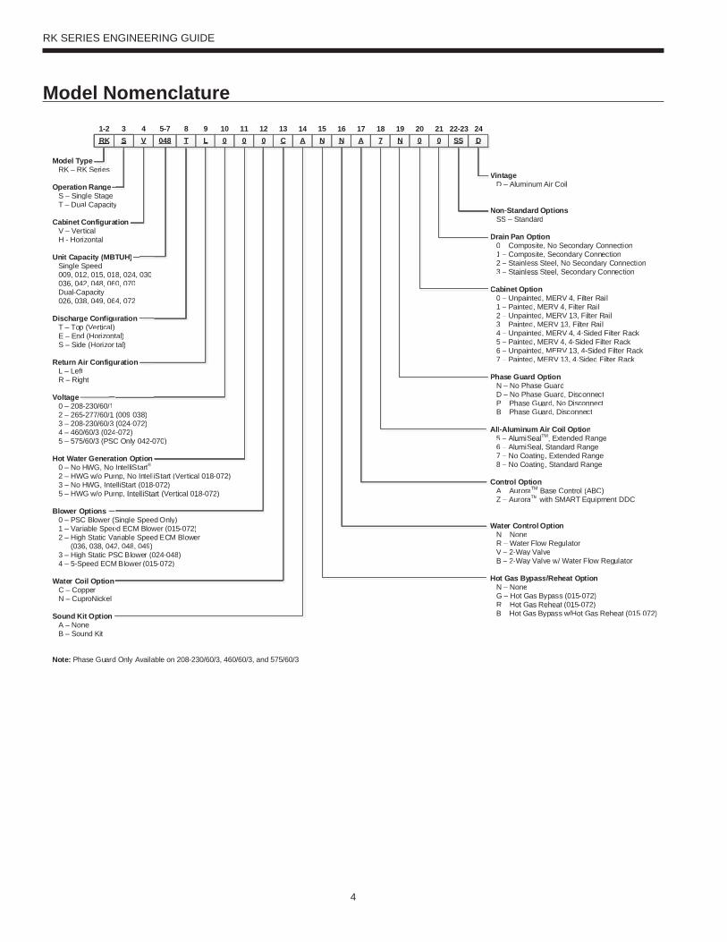
Model Nomenclature
Vintage D – Aluminum Air Coil
Non-Standard Options SS – Standard
Drain Pan Option 0 – Composite, No Secondary Connection 1 – Composite, Secondary Connection 2 – Stainless Steel, No Secondary Connection 3 – Stainless Steel, Secondary Connection
Cabinet Option 0 – Unpainted, MERV 4, Filter Rail 1 – Painted, MERV 4, Filter Rail 2 – Unpainted, MERV 13, Filter Rail 3 – Painted, MERV 13, Filter Rail 4 – Unpainted, MERV 4, 4-Sided Filter Rack 5 – Painted, MERV 4, 4-Sided Filter Rack 6 – Unpainted, MERV 13, 4-Sided Filter Rack 7 – Painted, MERV 13, 4-Sided Filter Rack
Phase Guard Option N – No Phase Guard D – No Phase Guard, Disconnect P – Phase Guard, No Disconnect B – Phase Guard, Disconnect
All-Aluminum Air Coil Option 5 – AlumiSealTM, Extended Range 6 – AlumiSeal, Standard Range 7 – No Coating, Extended Range 8 – No Coating, Standard Range
Control Option A – AuroraTM Base Control (ABC) Z – AuroraTM with SMART Equipment DDC
Water Control Option N – None R – Water Flow Regulator V – 2-Way Valve B – 2-Way Valve w/ Water Flow Regulator
Hot Gas Bypass/Reheat Option N – None G – Hot Gas Bypass (015-072) R – Hot Gas Reheat (015-072) B – Hot Gas Bypass w/Hot Gas Reheat (015-072)
RK S
Vintage D – Aluminum Air Coil
Non-Standard Options SS – Standard
Drain Pan Option 0 – Composite, No Secondary Connection 1 – Composite, Secondary Connection 2 – Stainless Steel, No Secondary Connection 3 – Stainless Steel, Secondary Connection
Cabinet Option 0 – Unpainted, MERV 4, Filter Rail 1 – Painted, MERV 4, Filter Rail 2 – Unpainted, MERV 13, Filter Rail 3 – Painted, MERV 13, Filter Rail 4 – Unpainted, MERV 4, 4-Sided Filter Rack 5 – Painted, MERV 4, 4-Sided Filter Rack 6 – Unpainted, MERV 13, 4-Sided Filter Rack 7 – Painted, MERV 13, 4-Sided Filter Rack
Phase Guard Option N – No Phase Guard D – No Phase Guard, Disconnect P – Phase Guard, No Disconnect
B – Phase Guard, Disconnect
All-Aluminum Air Coil Option 5 – AlumiSealTM, Extended Range 6 – AlumiSeal, Standard Range 7 – No Coating, Extended Range 8 – No Coating, Standard Range
Control OptionA – AuroraTM Base Control (ABC)
Z – AuroraTM with SMART Equipment DDC
Water Control Option N – None R – Water Flow Regulator V – 2-Way Valve B – 2-Way Valve w/ ww Water Flow Regulator
Hot Gas Bypass/Reheat Option N – None G – Hot Gas Bypass (015-072) R – Hot Gas Reheat (015-072) B – Hot Gas Bypass w/ww Hot Gas Reheat (015-072)
RK S1-2 4 5-7 8 9 10
Model Type RK – RK Series
Operation Range S – Single Stage T – Dual-Capacity
Cabinet Configuration V – Vertical H - Horizontal
Unit Capacity (MBTUH) Single Speed 009, 012, 015, 018, 024, 030 036, 042, 048, 060, 070 Dual-Capacity 026, 038, 049, 064, 072
Discharge Configuration T – Top (Vertical) E – End (Horizontal) S – Side (Horizontal)
Return Air Configuration L – Left R – Right
Voltage 0 – 208-230/60/1 2 – 265-277/60/1 (009-038) 3 – 208-230/60/3 (024-072) 4 – 460/60/3 (024-072) 5 – 575/60/3 (PSC Only 042-070)
Hot Water Generation Option 0 – No HWG, No IntelliStart® 2 – HWG w/o Pump, No IntelliStart (Vertical 018-072) 3 – No HWG, IntelliStart (018-072) 5 – HWG w/o Pump, IntelliStart (Vertical 018-072)
Blower Options 0 – PSC Blower (Single Speed Only) 1 – Variable Speed ECM Blower (015-072) 2 – High Static Variable Speed ECM Blower (036, 038, 042, 048, 049) 3 – High Static PSC Blower (024-048) 4 – 5-Speed ECM Blower (015-072)
Water Coil Option C – Copper N – CuproNickel
Sound Kit Option A – None B – Sound Kit
11 12 13 15V 048 T L 0 0 0 C A N
14N16
A17
ypeRK Series
on Rangengle Stageal-Capac
Configurrticalrizontal
pacity (MSpeed
12, 015, 042, 048, 0
Capacity38, 049, 0
ge Configp (Verticad (Horizo
de (Horizo
Air Configftght
/1/1 /3 24SC
rato um
nteum
s
ee
city
rat
BT
0106
064
gual)onton
gu
718
N19
020
021
SS22-23
D24
V
Note: Phase Guard Only Available on 208-230/60/3, 460/60/3, and 575/60/3
3
Single Speed Only) ed ECM Blower (015-072)ariable Speed ECM Blower2, 048, 049)SC Blower (024-048)
M Blower (015-072)
(009-038)(024-072)
4-072)C Only 042-0
tion OptionIntelliStart®tt
mp, No IntelliStart (Vertical 018-072)elliStart (018-072)mp, IntelliStart (Vertical 018-072)
y
ation
TUH)
8, 024, 00, 070
4, 072
uration
tal)tal)
uration
030
070)
5
RK SERIES ENGINEERING GUIDE
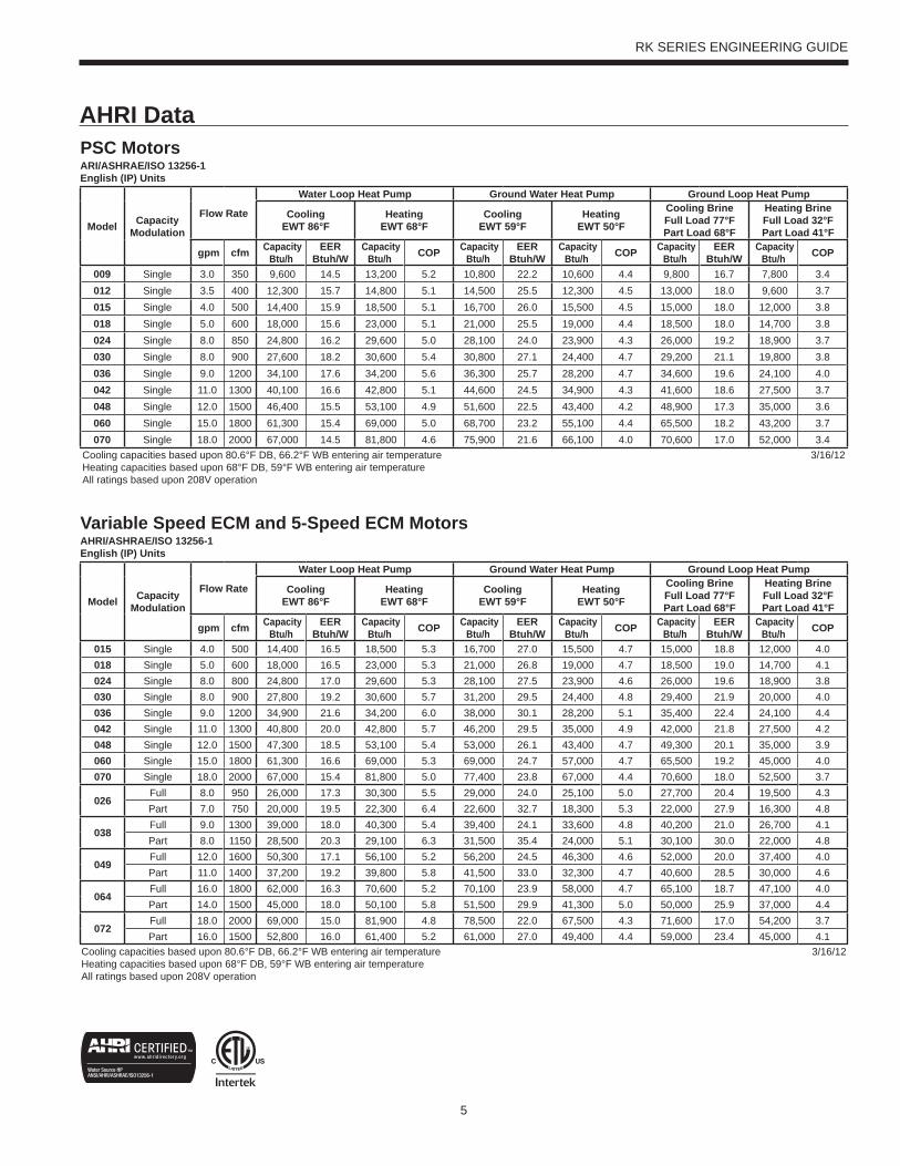
AHRI DataPSC MotorsARI/ASHRAE/ISO 13256-1English (IP) Units
Model Capacity Modulation
Flow Rate
Water Loop Heat Pump Ground Water Heat Pump Ground Loop Heat Pump
Cooling EWT 86°F
Heating EWT 68°F
Cooling EWT 59°F
Heating EWT 50°F
Cooling Brine Full Load 77°F Part Load 68°F
Heating Brine Full Load 32°F Part Load 41°F
gpm cfm CapacityBtu/h
EER Btuh/W
CapacityBtu/h COP Capacity
Btu/h EER
Btuh/W Capacity
Btu/h COP CapacityBtu/h
EER Btuh/W
CapacityBtu/h COP
009 Single 3.0 350 9,600 14.5 13,200 5.2 10,800 22.2 10,600 4.4 9,800 16.7 7,800 3.4012 Single 3.5 400 12,300 15.7 14,800 5.1 14,500 25.5 12,300 4.5 13,000 18.0 9,600 3.7015 Single 4.0 500 14,400 15.9 18,500 5.1 16,700 26.0 15,500 4.5 15,000 18.0 12,000 3.8018 Single 5.0 600 18,000 15.6 23,000 5.1 21,000 25.5 19,000 4.4 18,500 18.0 14,700 3.8024 Single 8.0 850 24,800 16.2 29,600 5.0 28,100 24.0 23,900 4.3 26,000 19.2 18,900 3.7030 Single 8.0 900 27,600 18.2 30,600 5.4 30,800 27.1 24,400 4.7 29,200 21.1 19,800 3.8036 Single 9.0 1200 34,100 17.6 34,200 5.6 36,300 25.7 28,200 4.7 34,600 19.6 24,100 4.0042 Single 11.0 1300 40,100 16.6 42,800 5.1 44,600 24.5 34,900 4.3 41,600 18.6 27,500 3.7048 Single 12.0 1500 46,400 15.5 53,100 4.9 51,600 22.5 43,400 4.2 48,900 17.3 35,000 3.6060 Single 15.0 1800 61,300 15.4 69,000 5.0 68,700 23.2 55,100 4.4 65,500 18.2 43,200 3.7070 Single 18.0 2000 67,000 14.5 81,800 4.6 75,900 21.6 66,100 4.0 70,600 17.0 52,000 3.4
Cooling capacities based upon 80.6°F DB, 66.2°F WB entering air temperatureHeating capacities based upon 68°F DB, 59°F WB entering air temperatureAll ratings based upon 208V operation
3/16/12
Variable Speed ECM and 5-Speed ECM MotorsAHRI/ASHRAE/ISO 13256-1English (IP) Units
Model Capacity Modulation
Flow Rate
Water Loop Heat Pump Ground Water Heat Pump Ground Loop Heat Pump
Cooling EWT 86°F
Heating EWT 68°F
Cooling EWT 59°F
Heating EWT 50°F
Cooling Brine Full Load 77°F Part Load 68°F
Heating Brine Full Load 32°F Part Load 41°F
gpm cfm Capacity Btu/h
EER Btuh/W
Capacity Btu/h COP Capacity
Btu/h EER
Btuh/W Capacity
Btu/h COP Capacity Btu/h
EER Btuh/W
Capacity Btu/h COP
015 Single 4.0 500 14,400 16.5 18,500 5.3 16,700 27.0 15,500 4.7 15,000 18.8 12,000 4.0018 Single 5.0 600 18,000 16.5 23,000 5.3 21,000 26.8 19,000 4.7 18,500 19.0 14,700 4.1024 Single 8.0 800 24,800 17.0 29,600 5.3 28,100 27.5 23,900 4.6 26,000 19.6 18,900 3.8030 Single 8.0 900 27,800 19.2 30,600 5.7 31,200 29.5 24,400 4.8 29,400 21.9 20,000 4.0036 Single 9.0 1200 34,900 21.6 34,200 6.0 38,000 30.1 28,200 5.1 35,400 22.4 24,100 4.4042 Single 11.0 1300 40,800 20.0 42,800 5.7 46,200 29.5 35,000 4.9 42,000 21.8 27,500 4.2048 Single 12.0 1500 47,300 18.5 53,100 5.4 53,000 26.1 43,400 4.7 49,300 20.1 35,000 3.9060 Single 15.0 1800 61,300 16.6 69,000 5.3 69,000 24.7 57,000 4.7 65,500 19.2 45,000 4.0070 Single 18.0 2000 67,000 15.4 81,800 5.0 77,400 23.8 67,000 4.4 70,600 18.0 52,500 3.7
026Full 8.0 950 26,000 17.3 30,300 5.5 29,000 24.0 25,100 5.0 27,700 20.4 19,500 4.3Part 7.0 750 20,000 19.5 22,300 6.4 22,600 32.7 18,300 5.3 22,000 27.9 16,300 4.8
038Full 9.0 1300 39,000 18.0 40,300 5.4 39,400 24.1 33,600 4.8 40,200 21.0 26,700 4.1Part 8.0 1150 28,500 20.3 29,100 6.3 31,500 35.4 24,000 5.1 30,100 30.0 22,000 4.8
049Full 12.0 1600 50,300 17.1 56,100 5.2 56,200 24.5 46,300 4.6 52,000 20.0 37,400 4.0Part 11.0 1400 37,200 19.2 39,800 5.8 41,500 33.0 32,300 4.7 40,600 28.5 30,000 4.6
064Full 16.0 1800 62,000 16.3 70,600 5.2 70,100 23.9 58,000 4.7 65,100 18.7 47,100 4.0Part 14.0 1500 45,000 18.0 50,100 5.8 51,500 29.9 41,300 5.0 50,000 25.9 37,000 4.4
072Full 18.0 2000 69,000 15.0 81,900 4.8 78,500 22.0 67,500 4.3 71,600 17.0 54,200 3.7Part 16.0 1500 52,800 16.0 61,400 5.2 61,000 27.0 49,400 4.4 59,000 23.4 45,000 4.1
Cooling capacities based upon 80.6°F DB, 66.2°F WB entering air temperatureHeating capacities based upon 68°F DB, 59°F WB entering air temperatureAll ratings based upon 208V operation
3/16/12
6
RK SERIES ENGINEERING GUIDE
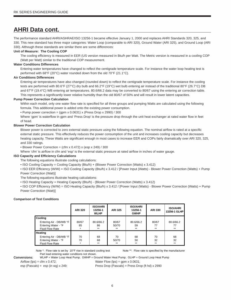
The performance standard AHRI/ASHRAE/ISO 13256-1 became effective January 1, 2000 and replaces AHRI Standards 320, 325, and 330. This new standard has three major categories: Water Loop (comparable to ARI 320), Ground Water (ARI 325), and Ground Loop (ARI 330). Although these standards are similar there are some differences:Unit of Measure: The Cooling COP
The cooling efficiency is measured in EER (US version measured in Btu/h per Watt. The Metric version is measured in a cooling COP (Watt per Watt) similar to the traditional COP measurement.
Water Conditions DifferencesEntering water temperatures have changed to reflect the centigrade temperature scale. For instance the water loop heating test is performed with 68°F (20°C) water rounded down from the old 70°F (21.1°C).
Air Conditions DifferencesEntering air temperatures have also changed (rounded down) to reflect the centigrade temperature scale. For instance the cooling tests are performed with 80.6°F (27°C) dry bulb and 66.2°F (19°C) wet bulb entering air instead of the traditional 80°F (26.7°C) DB and 67°F (19.4°C) WB entering air temperatures. 80.6/66.2 data may be converted to 80/67 using the entering air correction table. This represents a significantly lower relative humidity than the old 80/67 of 50% and will result in lower latent capacities.
Pump Power Correction CalculationWithin each model, only one water flow rate is specified for all three groups and pumping Watts are calculated using the following formula. This additional power is added onto the existing power consumption.• Pump power correction = (gpm x 0.0631) x (Press Drop x 2990) / 300Where ‘gpm’ is waterflow in gpm and ‘Press Drop’ is the pressure drop through the unit heat exchanger at rated water flow in feetof head.
Blower Power Correction CalculationBlower power is corrected to zero external static pressure using the following equation. The nominal airflow is rated at a specific external static pressure. This effectively reduces the power consumption of the unit and increases cooling capacity but decreases heating capacity. These Watts are significant enough in most cases to increase EER and COPs fairly dramatically over ARI 320, 325, and 330 ratings.• Blower Power Correction = (cfm x 0.472) x (esp x 249) / 300Where ‘cfm’ is airflow in cfm and ‘esp’ is the external static pressure at rated airflow in inches of water gauge.
ISO Capacity and Efficiency CalculationsThe following equations illustrate cooling calculations:• ISO Cooling Capacity = Cooling Capacity (Btu/h) + (Blower Power Correction (Watts) x 3.412)• ISO EER Efficiency (W/W) = ISO Cooling Capacity (Btu/h) x 3.412 / [Power Input (Watts) - Blower Power Correction (Watts) + Pump Power Correction (Watt)]The following equations illustrate heating calculations:• ISO Heating Capacity = Heating Capacity (Btu/h) - (Blower Power Correction (Watts) x 3.412)• ISO COP Efficiency (W/W) = ISO Heating Capacity (Btu/h) x 3.412 / [Power Input (Watts) - Blower Power Correction (Watts) + Pump Power Correction (Watt)]
Comparison of Test Conditions
Conversions: Airflow (lps) = cfm x 0.472; Water Flow (lps) = gpm x 0.0631; esp (Pascals) = esp (in wg) x 249; Press Drop (Pascals) = Press Drop (ft hd) x 2990
AHRI Data cont.
ARI 320ISO/AHRI 13256-1 WLHP
ARI 325ISO/AHRI 13256-1 GWHP
ARI 330 ISO/AHRI 13256-1 GLHP
CoolingEntering Air - DB/WB °F 80/67 80.6/66.2 80/67 80.6/66.2 80/67 80.6/66.2Entering Water - °F 85 86 50/70 59 77 77Fluid Flow Rate * ** ** ** ** **
HeatingEntering Air - DB/WB °F 70 68 70 68 70 68Entering Water - °F 70 68 50/70 50 32 32Fluid Flow Rate * ** ** ** ** **
Note *: Flow rate is set by 10°F rise in standard cooling test Note **: Flow rate is specified by the manufacturerPart load entering water conditions not shown.WLHP = Water Loop Heat Pump; GWHP = Ground Water Heat Pump; GLHP = Ground Loop Heat Pump
7
RK SERIES ENGINEERING GUIDE
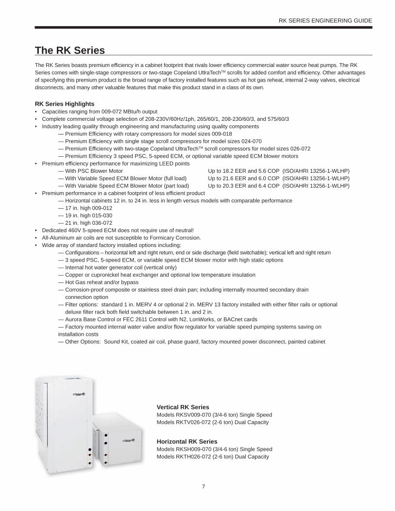
The RK SeriesThe RK Series boasts premium efficiency in a cabinet footprint that rivals lower efficiency commercial water source heat pumps. The RK Series comes with single-stage compressors or two-stage Copeland UtlraTechTM scrolls for added comfort and efficiency. Other advantages of specifying this premium product is the broad range of factory installed features such as hot gas reheat, internal 2-way valves, electrical disconnects, and many other valuable features that make this product stand in a class of its own.
RK Series Highlights • Capacities ranging from 009-072 MBtu/h output • Complete commercial voltage selection of 208-230V/60Hz/1ph, 265/60/1, 208-230/60/3, and 575/60/3• Industry leading quality through engineering and manufacturing using quality components — Premium Efficiency with rotary compressors for model sizes 009-018 — Premium Efficiency with single stage scroll compressors for model sizes 024-070 — Premium Efficiency with two-stage Copeland UltraTechTM scroll compressors for model sizes 026-072 — Premium Efficiency 3 speed PSC, 5-speed ECM, or optional variable speed ECM blower motors• Premium efficiency performance for maximizing LEED points — With PSC Blower Motor Up to 18.2 EER and 5.6 COP (ISO/AHRI 13256-1-WLHP) — With Variable Speed ECM Blower Motor (full load) Up to 21.6 EER and 6.0 COP (ISO/AHRI 13256-1-WLHP) — With Variable Speed ECM Blower Motor (part load) Up to 20.3 EER and 6.4 COP (ISO/AHRI 13256-1-WLHP)• Premium performance in a cabinet footprint of less efficient product — Horizontal cabinets 12 in. to 24 in. less in length versus models with comparable performance — 17 in. high 009-012 — 19 in. high 015-030 — 21 in. high 036-072• Dedicated 460V 5-speed ECM does not require use of neutral!• All-Aluminum air coils are not susceptible to Formicary Corrosion.• Wide array of standard factory installed options including: — Configurations – horizontal left and right return, end or side discharge (field switchable); vertical left and right return — 3 speed PSC, 5-speed ECM, or variable speed ECM blower motor with high static options — Internal hot water generator coil (vertical only) — Copper or cupronickel heat exchanger and optional low temperature insulation — Hot Gas reheat and/or bypass — Corrosion-proof composite or stainless steel drain pan; including internally mounted secondary drain connection option — Filter options: standard 1 in. MERV 4 or optional 2 in. MERV 13 factory installed with either filter rails or optional deluxe filter rack both field switchable between 1 in. and 2 in. — Aurora Base Control or FEC 2611 Control with N2, LonWorks, or BACnet cards — Factory mounted internal water valve and/or flow regulator for variable speed pumping systems saving on installation costs — Other Options: Sound Kit, coated air coil, phase guard, factory mounted power disconnect, painted cabinet
Vertical RK SeriesModels RKSV009-070 (3/4-6 ton) Single SpeedModels RKTV026-072 (2-6 ton) Dual Capacity
Horizontal RK SeriesModels RKSH009-070 (3/4-6 ton) Single SpeedModels RKTH026-072 (2-6 ton) Dual Capacity
8
RK SERIES ENGINEERING GUIDE
The RK Series cont.
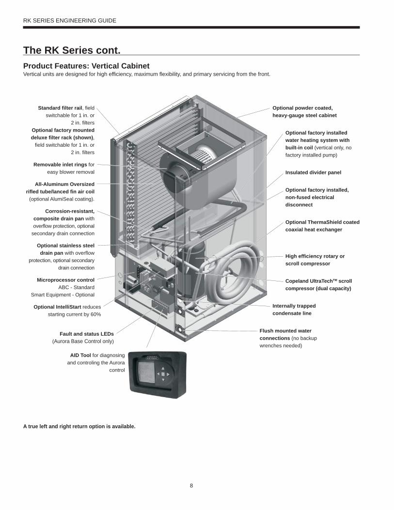
Standard filter rail, field switchable for 1 in. or
2 in. filtersOptional factory mounted deluxe filter rack (shown),
field switchable for 1 in. or2 in. filters
Optional powder coated, heavy-gauge steel cabinet
Corrosion-resistant, composite drain pan with overflow protection, optional
secondary drain connection
Optional factory installed water heating system with built-in coil (vertical only, no factory installed pump)
Internally trappedcondensate line
All-Aluminum Oversized rifled tube/lanced fin air coil
(optional AlumiSeal coating).
Insulated divider panel
Fault and status LEDs (Aurora Base Control only)
Product Features: Vertical Cabinet Vertical units are designed for high efficiency, maximum flexibility, and primary servicing from the front.
A true left and right return option is available.
Microprocessor controlABC - Standard
Smart Equipment - Optional
Removable inlet rings for easy blower removal
Flush mounted water connections (no backup wrenches needed)
Optional ThermaShield coated coaxial heat exchanger
Optional stainless steel drain pan with overflow
protection, optional secondary drain connection
High efficiency rotary or scroll compressor
Optional IntelliStart reduces starting current by 60%
Optional factory installed, non-fused electrical disconnect
Copeland UltraTechTM scroll compressor (dual capacity)
AID Tool for diagnosing and controling the Aurora
control
9
RK SERIES ENGINEERING GUIDE
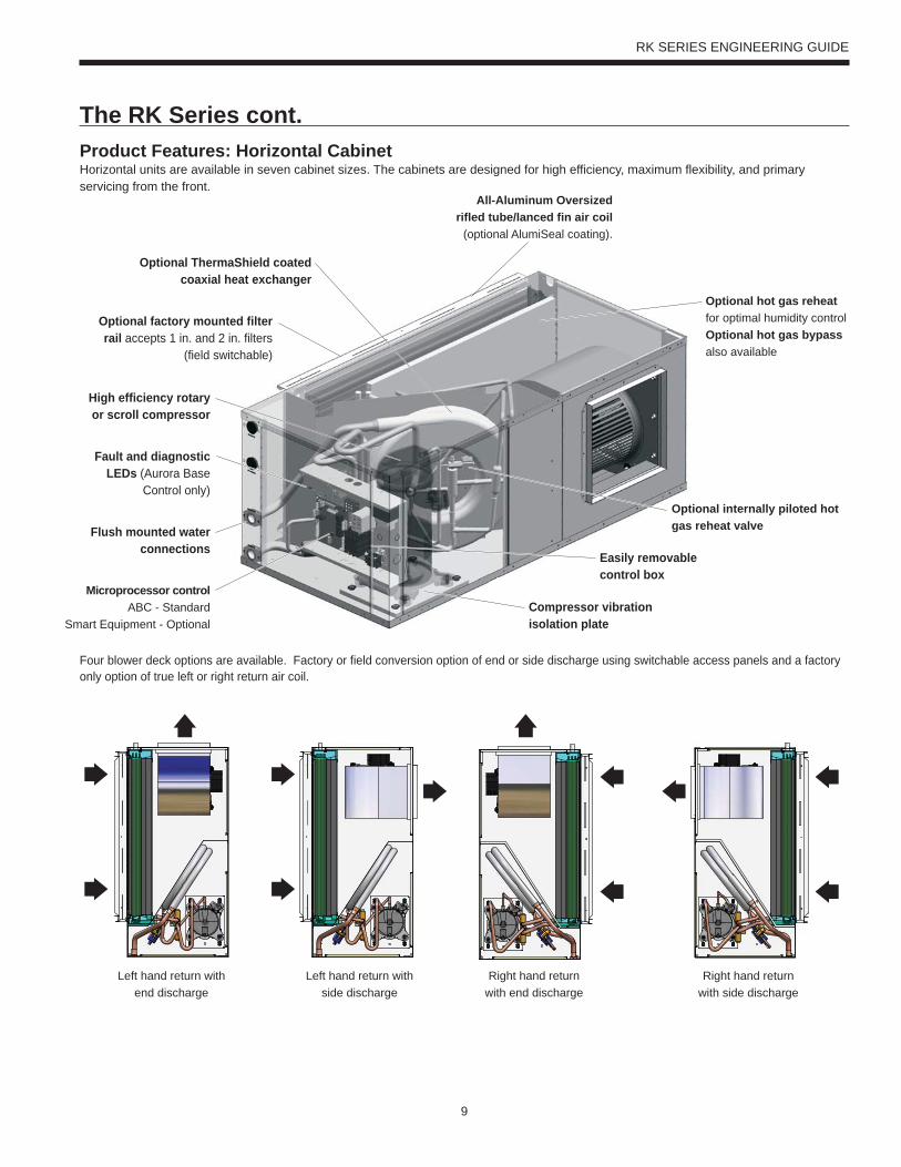
Optional hot gas reheat for optimal humidity controlOptional hot gas bypass also available
Optional factory mounted filter rail accepts 1 in. and 2 in. filters
(field switchable)
Easily removablecontrol box
High efficiency rotary or scroll compressor
Fault and diagnostic LEDs (Aurora Base
Control only)
Product Features: Horizontal CabinetHorizontal units are available in seven cabinet sizes. The cabinets are designed for high efficiency, maximum flexibility, and primary servicing from the front.
Four blower deck options are available. Factory or field conversion option of end or side discharge using switchable access panels and a factory only option of true left or right return air coil.
The RK Series cont.
Left hand return with end discharge
Left hand return with side discharge
Right hand return with end discharge
Right hand return with side discharge
Microprocessor controlABC - Standard
Smart Equipment - Optional
Optional ThermaShield coated coaxial heat exchanger
Flush mounted water connections
Optional internally piloted hot gas reheat valve
Compressor vibration isolation plate
All-Aluminum Oversized rifled tube/lanced fin air coil
(optional AlumiSeal coating).
10
RK SERIES ENGINEERING GUIDE
Flexible Product with Several Standard Options• Compact cabinet design, vertical and horizontal with true left and
right return configurations• Horizontal end and side discharge with vertical top discharge
air configurations• Capacities of 9,000 through 70,000 Btu/h for single speed models• Capacities of 26,000 through 72,000 Btu/h for dual capacity models• All commercial voltages including 208-230/60/1,
265-277/60/1, 208-230/60/3, 460/60/3, and 575/60/3.• Hot water generation (hot water generator - vertical only)• 3 speed PSC, 5-speed ECM, or optional variable speed ECM
blower motors (high static options available)• All-Aluminum air coils with optional AlumiSeal coating• Copper or cupronickel heat exchangers• Extended range insulation option• Super Quiet Sound Package, including multi-density
compressor blanket• Quiet rotary or scroll compressors in all models • 2-dimension refrigerant piping vibration loops to isolate the compressor • Double isolated compressor mounting utilizing eight durometer selected rubber grommets• Heavy gauge cabinet and vibration isolating hanger brackets• Hot Gas Bypass and Reheat (015-072)• Internally mounted water flow regulator and/or water solenoid
valve for variable speed pumping systems• Standard Aurora Base Control or FEC 2611 Control with optional
N2, Lonworks, or BACnet DDC cards• Phase guard with optional ‘dial’ disconnect• Optional painted cabinet• Polymer composite drain pan or stainless steel drain pan with
optional secondary drain connection• 1 in. MERV 4 or 2 in. MERV 13 filters• 3rd party sound tested to AHRI 260
Other options are available by special request, contact yoursales representative.
Premium EfficiencyThe RK Series is a premium efficiency water source heat pump in a compact vertical and horizontal cabinet. The product features highly efficient and reliable single capacity rotary or scroll compressors or dual capacity Copeland UltraTech scroll compressors, mated with large blowers. These blowers are driven by efficient 3 speed PSC blower motors, 5-speed ECM blower motors, or highly efficient variable speed ECM blower motors.
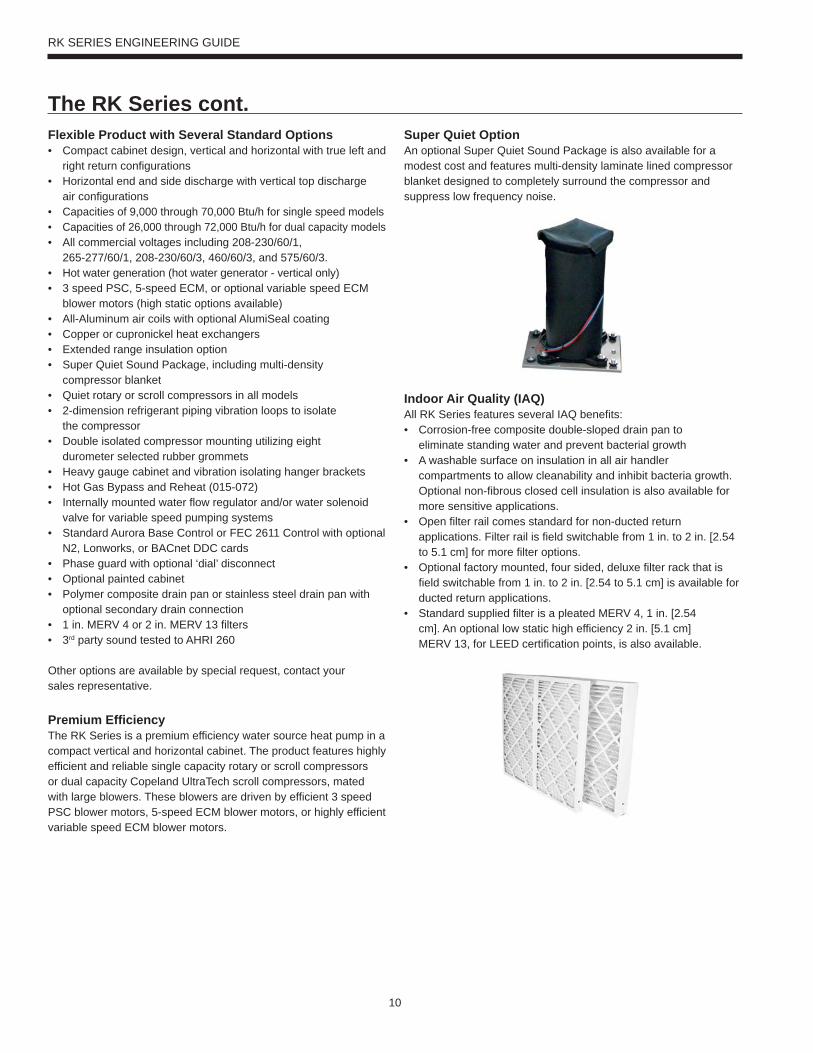
Super Quiet OptionAn optional Super Quiet Sound Package is also available for a modest cost and features multi-density laminate lined compressor blanket designed to completely surround the compressor and suppress low frequency noise.
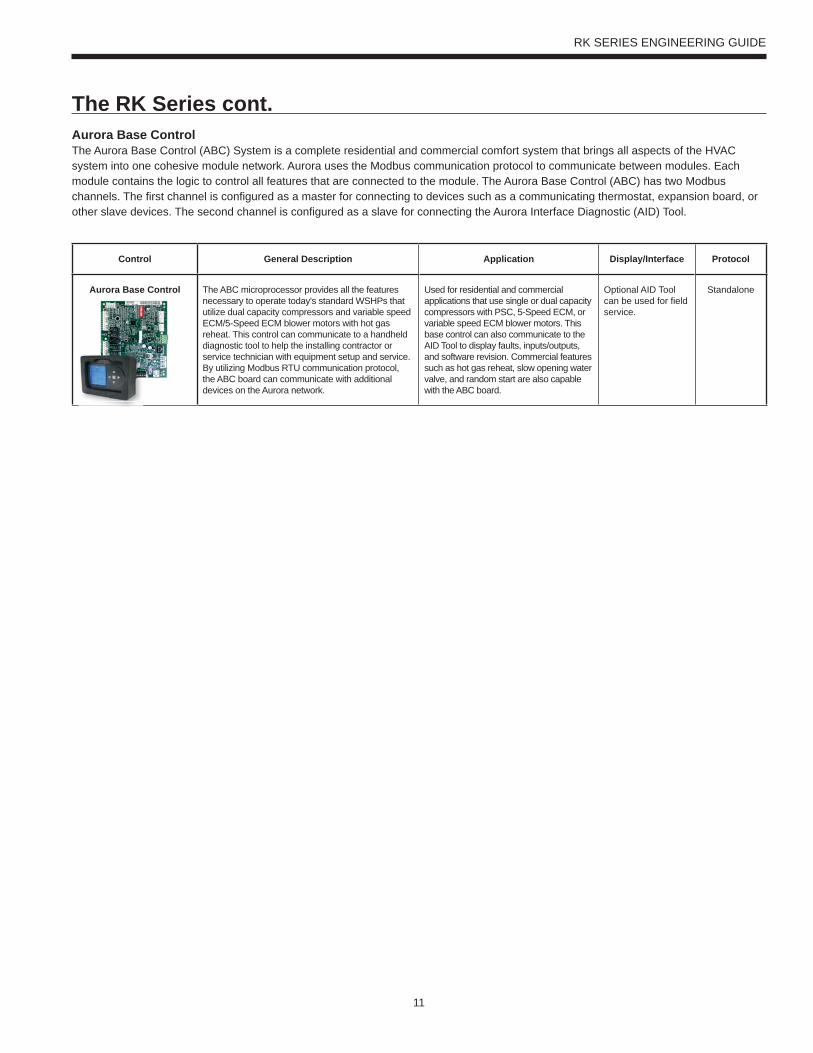
Indoor Air Quality (IAQ)All RK Series features several IAQ benefits:• Corrosion-free composite double-sloped drain pan to
eliminate standing water and prevent bacterial growth• A washable surface on insulation in all air handler
compartments to allow cleanability and inhibit bacteria growth. Optional non-fibrous closed cell insulation is also available for more sensitive applications.
• Open filter rail comes standard for non-ducted return applications. Filter rail is field switchable from 1 in. to 2 in. [2.54 to 5.1 cm] for more filter options.
• Optional factory mounted, four sided, deluxe filter rack that is field switchable from 1 in. to 2 in. [2.54 to 5.1 cm] is available for ducted return applications.
• Standard supplied filter is a pleated MERV 4, 1 in. [2.54 cm]. An optional low static high efficiency 2 in. [5.1 cm] MERV 13, for LEED certification points, is also available.
The RK Series cont.
11
RK SERIES ENGINEERING GUIDE
Control General Description Application Display/Interface Protocol
Aurora Base Control The ABC microprocessor provides all the features necessary to operate today's standard WSHPs that utilize dual capacity compressors and variable speed ECM/5-Speed ECM blower motors with hot gas reheat. This control can communicate to a handheld diagnostic tool to help the installing contractor or service technician with equipment setup and service. By utilizing Modbus RTU communication protocol, the ABC board can communicate with additional devices on the Aurora network.
Used for residential and commercial applications that use single or dual capacity compressors with PSC, 5-Speed ECM, or variable speed ECM blower motors. This base control can also communicate to the AID Tool to display faults, inputs/outputs, and software revision. Commercial features such as hot gas reheat, slow opening water valve, and random start are also capable with the ABC board.
Optional AID Tool can be used for field service.
Standalone
The RK Series cont.Aurora Base ControlThe Aurora Base Control (ABC) System is a complete residential and commercial comfort system that brings all aspects of the HVAC system into one cohesive module network. Aurora uses the Modbus communication protocol to communicate between modules. Each module contains the logic to control all features that are connected to the module. The Aurora Base Control (ABC) has two Modbus channels. The first channel is configured as a master for connecting to devices such as a communicating thermostat, expansion board, or other slave devices. The second channel is configured as a slave for connecting the Aurora Interface Diagnostic (AID) Tool.
12
RK SERIES ENGINEERING GUIDE
Internally Mounted Solenoid Valve OptionWhen variable speed circulating pump systems are designed, low pressure drop (high Cv) solenoid valves are specified at each unit to vary the pump according to flow required. It is important that these valves be low pressure drop to avoid unwanted pump watts. This option factory installs this valve inside the unit.
Secondary Drain Connection OptionSome local building authority’s interpretation of codes require more condensate overflow protection than standard microprocessor based condensate sensors offer. In these areas a full secondary drain pan might be required causing both increased cost and unit service access issues. In many of these cases a secondary drain connection option can be added to the unit to pass this local interpretation of condensate drain redundancy. This option adds a second PVC drain connection to the drain pan at a higher level.
Hot Gas Bypass/ReheatThe hot gas bypass option is designed to limit the minimum evaporating pressure in the cooling mode to prevent the air coil from icing. Hot gas reheat option provides consistent comfort by removing moisture from the air without over cooling the space. These options are available together or standalone.
Phase Guard MonitorFactory mounted phase guard device is available to protect the compressor against loss of phase and reverse rotation.
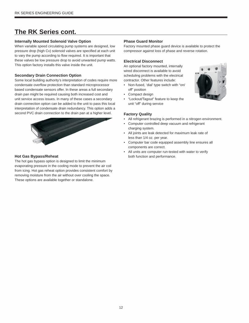
Electrical DisconnectAn optional factory mounted, internally wired disconnect is available to avoid scheduling problems with the electrical contractor. Other features include:• Non-fused, ‘dial’ type switch with “on/
off” position• Compact design • “Lockout/Tagout” feature to keep the
unit “off” during service
Factory Quality• All refrigerant brazing is performed in a nitrogen environment. • Computer controlled deep vacuum and refrigerant
charging system.• All joints are leak detected for maximum leak rate of
less than 1/4 oz. per year.• Computer bar code equipped assembly line ensures all
components are correct.• All units are computer run-tested with water to verify
both function and performance.
The RK Series cont.
13
RK SERIES ENGINEERING GUIDE
RefrigerantRK Series products all feature zero ozone depletion and low global warming potential refrigerant R-410A.
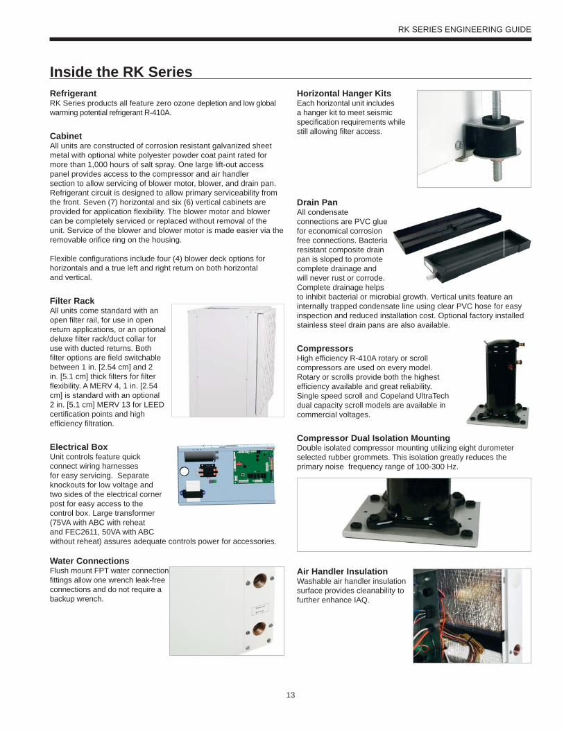
CabinetAll units are constructed of corrosion resistant galvanized sheet metal with optional white polyester powder coat paint rated for more than 1,000 hours of salt spray. One large lift-out access panel provides access to the compressor and air handler section to allow servicing of blower motor, blower, and drain pan. Refrigerant circuit is designed to allow primary serviceability from the front. Seven (7) horizontal and six (6) vertical cabinets are provided for application flexibility. The blower motor and blower can be completely serviced or replaced without removal of the unit. Service of the blower and blower motor is made easier via the removable orifice ring on the housing.
Flexible configurations include four (4) blower deck options for horizontals and a true left and right return on both horizontaland vertical.
Filter RackAll units come standard with an open filter rail, for use in open return applications, or an optional deluxe filter rack/duct collar for use with ducted returns. Both filter options are field switchable between 1 in. [2.54 cm] and 2 in. [5.1 cm] thick filters for filter flexibility. A MERV 4, 1 in. [2.54 cm] is standard with an optional 2 in. [5.1 cm] MERV 13 for LEED certification points and high efficiency filtration.
Electrical BoxUnit controls feature quick connect wiring harnesses for easy servicing. Separate knockouts for low voltage and two sides of the electrical corner post for easy access to the control box. Large transformer (75VA with ABC with reheat and FEC2611, 50VA with ABC without reheat) assures adequate controls power for accessories.
Water ConnectionsFlush mount FPT water connection fittings allow one wrench leak-free connections and do not require a backup wrench.
Horizontal Hanger KitsEach horizontal unit includes a hanger kit to meet seismic specification requirements while still allowing filter access.
Drain PanAll condensate connections are PVC glue for economical corrosion free connections. Bacteria resistant composite drain pan is sloped to promote complete drainage and will never rust or corrode. Complete drainage helps to inhibit bacterial or microbial growth. Vertical units feature an internally trapped condensate line using clear PVC hose for easy inspection and reduced installation cost. Optional factory installed stainless steel drain pans are also available.
CompressorsHigh efficiency R-410A rotary or scroll compressors are used on every model.Rotary or scrolls provide both the highest efficiency available and great reliability. Single speed scroll and Copeland UltraTech dual capacity scroll models are available in commercial voltages.
Compressor Dual Isolation MountingDouble isolated compressor mounting utilizing eight durometer selected rubber grommets. This isolation greatly reduces the primary noise frequency range of 100-300 Hz.
Air Handler InsulationWashable air handler insulation surface provides cleanability to further enhance IAQ.
Inside the RK Series
14
RK SERIES ENGINEERING GUIDE
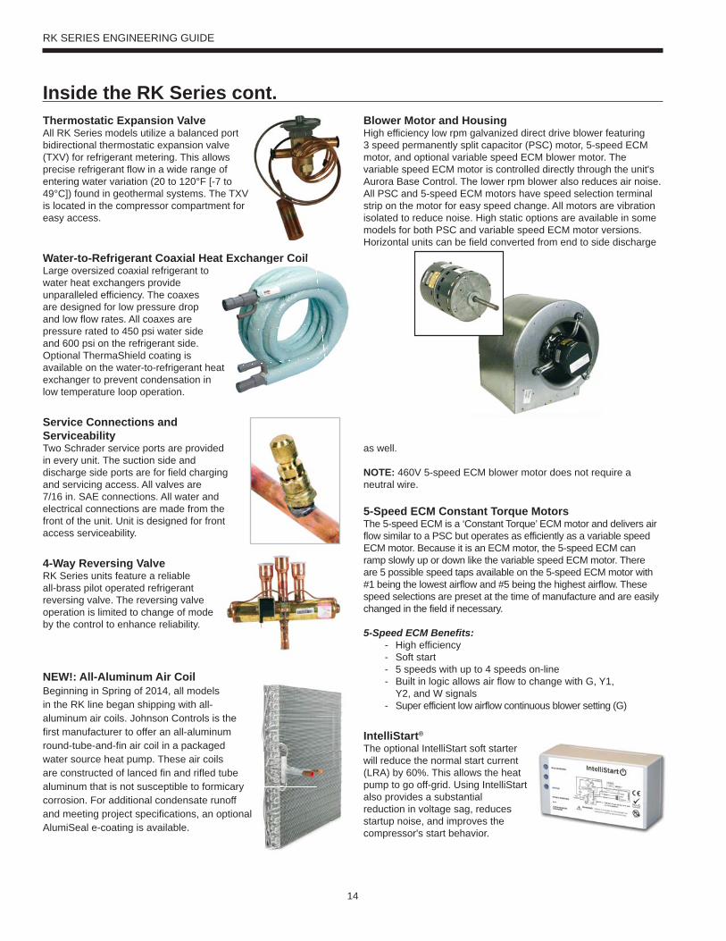
Thermostatic Expansion ValveAll RK Series models utilize a balanced port bidirectional thermostatic expansion valve (TXV) for refrigerant metering. This allows precise refrigerant flow in a wide range of entering water variation (20 to 120°F [-7 to 49°C]) found in geothermal systems. The TXV is located in the compressor compartment for easy access.
Water-to-Refrigerant Coaxial Heat Exchanger CoilLarge oversized coaxial refrigerant towater heat exchangers provide unparalleled efficiency. The coaxes are designed for low pressure drop and low flow rates. All coaxes are pressure rated to 450 psi water side and 600 psi on the refrigerant side. Optional ThermaShield coating is available on the water-to-refrigerant heat exchanger to prevent condensation in low temperature loop operation.
Service Connections andServiceabilityTwo Schrader service ports are provided in every unit. The suction side and discharge side ports are for field charging and servicing access. All valves are 7/16 in. SAE connections. All water and electrical connections are made from the front of the unit. Unit is designed for front access serviceability.
4-Way Reversing ValveRK Series units feature a reliable all-brass pilot operated refrigerant reversing valve. The reversing valve operation is limited to change of mode by the control to enhance reliability.
NEW!: All-Aluminum Air CoilBeginning in Spring of 2014, all models in the RK line began shipping with all-aluminum air coils. Johnson Controls is the first manufacturer to offer an all-aluminum round-tube-and-fin air coil in a packaged water source heat pump. These air coils are constructed of lanced fin and rifled tube aluminum that is not susceptible to formicary corrosion. For additional condensate runoff and meeting project specifications, an optional AlumiSeal e-coating is available.
Blower Motor and HousingHigh efficiency low rpm galvanized direct drive blower featuring 3 speed permanently split capacitor (PSC) motor, 5-speed ECM motor, and optional variable speed ECM blower motor. The variable speed ECM motor is controlled directly through the unit's Aurora Base Control. The lower rpm blower also reduces air noise. All PSC and 5-speed ECM motors have speed selection terminal strip on the motor for easy speed change. All motors are vibration isolated to reduce noise. High static options are available in some models for both PSC and variable speed ECM motor versions. Horizontal units can be field converted from end to side discharge
as well.
NOTE: 460V 5-speed ECM blower motor does not require a neutral wire.
5-Speed ECM Constant Torque MotorsThe 5-speed ECM is a ‘Constant Torque’ ECM motor and delivers air flow similar to a PSC but operates as efficiently as a variable speed ECM motor. Because it is an ECM motor, the 5-speed ECM can ramp slowly up or down like the variable speed ECM motor. There are 5 possible speed taps available on the 5-speed ECM motor with #1 being the lowest airflow and #5 being the highest airflow. These speed selections are preset at the time of manufacture and are easily changed in the field if necessary.
5-Speed ECM Benefits:- High efficiency- Soft start- 5 speeds with up to 4 speeds on-line- Built in logic allows air flow to change with G, Y1, Y2, and W signals- Super efficient low airflow continuous blower setting (G)
IntelliStart®
The optional IntelliStart soft starter will reduce the normal start current (LRA) by 60%. This allows the heat pump to go off-grid. Using IntelliStart also provides a substantial reduction in voltage sag, reduces startup noise, and improves the compressor's start behavior.
anger Coil
Inside the RK Series cont.
15
RK SERIES ENGINEERING GUIDE
Aurora ‘Base’ Control
NOTE: Refer to the Aurora Base Control Application and Troubleshooting Guide and the Instruction Guide: Aurora Interface and Diagnostics (AID) Tool for additional information.
Control FeaturesSoftware ABC Standard Version 2.0Single or Dual Capacity CompressorsEither single or dual capacity compressors can be operated.
ECM Blower Motor OptionAn ECM blower motor can be driven directly using the onboard PWM output. Four blower speeds are available based upon the G, Y1, Y2, and W input signals to the board. The blower speeds can be changed either by the ECM manual configurations mode method or by using the Aurora AID Tool directly. All four blower speeds can be set to the same speed if desired.
5-Speed ECM Blower Motor OptionA 5-Speed ECM blower motor will be driven directly using the thermostat connections. Any of the G, Y1, or Y2/W signals can drive any of the 5 available pre-programmed blower speeds on the motor.
Other Control Features• Random start at power up• Anti-short cycle protection• High and low pressure cutouts• Loss of charge• Water coil freeze detection• Air coil freeze detection• Over/under voltage protection• Condensate overflow sensor• Load shed• Dehumidification (where applicable)• Emergency shutdown• Hot gas reheat operation (where applicable)• Diagnostic LED• Test mode push button switch• Two auxiliary electric heat outputs• Alarm output• Accessory output with N.O. and N.C.• Modbus communication (master)• Modbus communication (slave)
Field Selectable Options via HardwareDIP Switch (SW1) – Test/Configuration Button (See SW1 Operation Table)
Test ModeThe control is placed in the test mode by holding the push button switch SW1 for 2 - 5 seconds. In test mode most of the control timings will be shortened by a factor of sixteen (16). LED3 (green) will flash at 1 second on and 1 second off. Additionally, when entering test mode LED1 (red) will flash the last lockout one time. Test mode will automatically time out after 30 minutes. Test mode can be exited by pressing and holding the SW1 button for 2 to 5 seconds or by cycling the power. NOTE: Test mode will automatically be exited after 30 minutes.
ECM Configuration ModeThe control is placed in the ECM configuration mode by holding the pushbutton switch SW1 for 5 to 10 seconds, the high, low, and “G” ECM speeds can be selected by following the LED display lights. LED2 (yellow) will fast flash when entering the ECM configuration. When setting “G” speed LED3 (green) will be continuously lit, for low speed LED1 (red) will be continuously lit, and for high speed both LED3 (green) and LED1 (red) will be continuously lit. During the ECM configuration mode LED2 (yellow) will flash each of the 12 possible blower speeds 3 times. When the desired speed is flashed press SW1, LED2 will fast flash until SW1 is released. “G” speed has now been selected. Next select low speed, and high speed blower selections following the same process above. After third selection has been made, the control will exit the ECM configuration mode. Aux fan speed will remain at default or current setting and requires the AID Tool for adjustment.
Reset Configuration ModeThe control is placed in reset configuration mode by holding the push button switch SW1 for 50 to 60 seconds. This will reset all configuration settings and the EEPROM back to the factory default settings. LED3 (green) will turn off when entering reset configuration mode. Once LED3 (green) turns off, release SW1 and the control will reset.
DIP Switch (SW2) SW2-1 FP1 Selection – Low water coil temperature limit setting
for freeze detection. On = 30°F; Off = 15°F.SW2-2 FP2 Selection – On = 30°F; Off = N/ASW2-3 RV – O/B - thermostat type. Heat pump thermostats
with “O” output in cooling or “B” output in Heating can be selected. On = O; Off = B.
SW2-4 Access Relay Operation (P2)and 2-5
Access Relay Operation SW2-4 SW2-5Cycle with Blower ON ON
Cycle with Compressor OFF OFFWater Valve Slow Opening ON OFF
Cycle with Comm. T-stat Hum Cmd OFF ON
Controls - Aurora Base Control
16
RK SERIES ENGINEERING GUIDE
Cycle with Blower - The accessory relay will cycle with the blower output.
Cycle with Compressor - The accessory relay will cycle with the compressor output.
Water Valve Slow Opening - The accessory relay will cycle and delay both the blower and compressor output for 90 seconds.
SW2-6 CC Operation – selection of single or dual capacity compressor. On = Single Stage; Off = Dual Capacity
SW2-7 Lockout and Alarm Outputs (P2) – selection of a continuous or pulsed output for both the LO and ALM Outputs. On = Continuous; Off = Pulsed
SW2-8 Future Use
Alarm Jumper Clip SelectionFrom the factory, ALM is connected to 24 VAC via JW2. By cutting JW2, ALM becomes a dry contact connected to ALG.
ECM Blower SpeedsThe blower speeds can be changed either by using the ECM manual configurations mode method or by using the Aurora AID Tool directly (see Instruction Guide: Aurora Interface and Diagnostics (AID) Tool topic).
Field Selectable Options via Software(Selectable via the Aurora AID Tool)ECM Blower SpeedsAn ECM blower motor can be driven directly using the onboard PWM output. Four blower speeds are available, based upon the “G”, Y1 (low), Y2 (high), and Aux input signals to the board. The blower speeds can be changed either by the ECM manual configurations mode method (see ECM Configuration Mode topic) or by using the Aurora AID Tool directly. All four blower speeds can be set to the same speed if desired. Aux blower speed will remain at default or current setting and requires the AID Tool for adjustment.
Safety FeaturesThe following safety features are provided to protect the compressor, heat exchangers, wiring and other components from damage caused by operation outside of design conditions.
Fuse – a 3 amp automotive type plug-in fuse provides protection against short circuit or overload conditions.
Anti-Short Cycle Protection – 4 minute anti-short cycle protection for the compressor.
Random Start – 5 to 80 second random start upon power up.
Fault Retry – in the fault condition, the control will stage off the outputs and then “try again” to satisfy the thermostat Y input call. Once the thermostat input calls are satisfied, the control will continue on as if no fault occurred. If 3 consecutive faults occur without satisfying the thermostat Y input call, then the control will go to Lockout mode.
Lockout – when locked out, the blower will operate continuously in “G” speed, and PSC blower motor output will remain on. The Alarm output (ALM) and Lockout output (L) will be turned on. The fault type identification display LED1 (Red) shall flash the fault code. To reset lockout conditions with SW2-8 On, thermostat inputs “Y1”, “Y2”, and “W” must be removed for at least 3 seconds. To reset lockout conditions with SW2-8 Off, thermostat inputs “Y1”, “Y2”, “W”, and “DH” must be removed for at least 3 seconds. Lockout may also be reset by turning power off for at least 30 seconds or by enabling the emergency shutdown input for at least 3 seconds.
Lockout With Emergency Heat - if the control is locked out in the heating mode, and a Y2 or W input is received, the control will operate in the emergency heat mode while the compressor is locked out. The first emergency heat output will be energized 10 seconds after the W input is received, and the blower will shift to high speed. If the control remains locked out, and the W input is present, additional stage of emergency heat will stage on after 2 minutes. When the W input is removed, all of the emergency heat outputs will turn off, and the ECM blower will shift to “G” speed and PSC blower motor output will remain on.
High Pressure – fault is recognized when the Normally Closed High Pressure Switch, P4-9/10 opens, no matter how momentarily. The High Pressure Switch is electrically in series with the Compressor Contactor and serves as a hard-wired limit switch if an overpressure condition should occur.
Low Pressure - fault is recognized when the Normally Closed Low Pressure Switch, P4-7/8 is continuously open for 30 seconds. Closure of the LPS any time during the 30 second recognition time restarts the 30 second continuous open requirement. A continuously open LPS shall not be recognized during the 2 minute startup bypass time.
Loss of Charge – fault is recognized when the Normally Closed Low Pressure Switch, P4-7/8 is open prior to the compressor starting.
Condensate Overflow - fault is recognized when the impedance between this line and 24 VAC common or chassis ground drops below 100K ohms for 30 seconds continuously.
Freeze Detection (Coax) - set points shall be either 30°F or 15°F. When the thermistor temperature drops below the selected set point, the control shall begin counting down the 30 seconds delay. If the thermistor value rises above the selected set point, then the count should reset. The resistance value must remain below the selected set point for the entire length of the appropriate delay to be recognized as a fault. This fault will be ignored for the initial 2 minutes of the compressor run time.
Freeze Detection (Air Coil) - uses the FP2 input to protect against ice formation on the air coil. The FP2 input will operate exactly like FP1 except that the set point is 30 degrees and is not field adjustable.
Controls - Aurora Base Control cont.
17
RK SERIES ENGINEERING GUIDE
Over/Under Voltage Shutdown - An over/under voltage condition exists when the control voltage is outside the range of 18 VAC to 30 VAC. If the over/under voltage shutdown lasts for 15 minutes, the lockout and alarm relay will be energized. Over/under voltage shutdown is self-resetting in that if the voltage comes back within range of 18 VAC to 30 VAC for at least 0.5 seconds, then normal operation is restored.
Operation DescriptionPower Up - The unit will not operate until all the inputs and safety controls are checked for normal conditions. The unit has a 5 to 80 second random start delay at power up. Then the compressor has a 4 minute anti-short cycle delay after the random start delay.
Standby In standby mode, Y1, Y2, W, DH, and G are not active. Input O may be active. The blower and compressor will be off.
Heating OperationHeating, 1st Stage (Y1) - The blower is started on “G” speed immediately and the compressor is energized 10 seconds after the Y1 input is received. The ECM blower motor is switched to low speed 15 seconds after the Y1 input.
Heating, 2nd Stage (Y1, Y2) - The compressor will be staged to full capacity 20 seconds after Y2 input is received. The ECM blower will shift to high speed 15 seconds after the Y2 input is received.
Heating, 3rd Stage (Y1, Y2, W) - The hot water pump is de-energized and the first stage of electric heat is energized 10 seconds after the W command is received. If the demand continues the second stage of electric heat will be energized after 5 minutes.
Emergency Heat (W) - The blower will be started on “G” speed, 10 seconds later the first stage of electric heat will be turned on. 5 seconds after the first stage of electric heat is energized the blower will shift to Aux speed. If the emergency heat demand is not satisfied after 2 minutes the second electric heat stage will be energized.
Blower (G) - The blower will start immediately upon receiving a thermostat G command. If there are no other commands from the thermostat the ECM will run on “G” speed until the G command is removed. Regardless of blower input (G) from the thermostat, the blower will remain on for 30 seconds at the end of each heating cycle.
Cooling OperationIn all cooling operations, the reversing valve directly tracks the O input. Thus, anytime the O input is present, the reversing valve will be energized.
Cooling, 1st Stage (Y1, O) - The blower is started on “G” speed immediately and the compressor is energized 10 seconds after the Y1 input is received. The ECM blower motor is switched to low speed 15 seconds after the Y1 input.
Cooling, 2nd Stage (Y1, Y2, O) - The compressor will be staged to full capacity 20 seconds after Y2 input is received. The ECM blower will shift to high speed 15 seconds after the Y2 input is received.
Blower (G) - The blower will start immediately upon receiving a thermostat G command. If there are no other commands from the thermostat the ECM will run on “G” speed until the G command is removed. Regardless of blower input (G) from the thermostat, the blower will remain on for 30 seconds at the end of each heating, cooling, and emergency heat cycle.
Dehumidification (Y1, O, DH or Y1, Y2, O, DH) - When a DH command is received from the thermostat during a compressor call for cooling the ECM blower speed will be reduced by 15% to increase dehumidification.
Emergency Shutdown - Four (4) seconds after a valid ES input, P2-7 is present, all control outputs will be turned off and remain off until the emergency shutdown input is no longer present. The first time that the compressor is started after the control exits the emergency shutdown mode, there will be an anti-short cycle delay followed by a random start delay. Input must be tied to common to activate.
Continuous Blower Operation - The blower output will be energized any time the control has a G input present, unless the control has an emergency shutdown input present. The blower output will be turned off when G input is removed.
Load Shed - The LS input disables all outputs with the exception of the blower output. When the LS input has been cleared, the anti-short cycle timer and random start timer will be initiated. Input must be tied to common to activate.
Controls - Aurora Base Control cont.
18
RK SERIES ENGINEERING GUIDE
CC2
EH1
Fact
oryFaul t
ALG
ALMLSES ACC
c
Status
AURORA BASE CONTROL™
RV – K1
CC2
CC – K2
CC Hi – K3
Fan – K4
Alarm – K5
Acc – K6
ACC
no
ACC
nc
O/BCRLO G Y1 Y2 W DH
3A-Fu
se
O/BCRLO G Y1 Y2 W DH
LOG
HICCGCCFGFR
HPHPLP
FP2FP2FP1
REVREV
CFM
PWM
ECM PWM
Fact
ory
Factory Fan Connection
R R
CC
C
RS 48
5
EH2C
EH1C
CO
(+)(-)RCRS
485 E
xpFa
ctory
Com1
Com2
Config
G
G
G
YR
SW1 Test
FP1 – 15oF/30oF
JW2 - Alarm
P11
P5
P2 P1
P8
P7
P9
P6
P3
SW2
P13P4 FP2 – 15oF/30oF
RV – B/OACC – Dip 4
ACC – Dip 5CC – Dual/Single
L – Pulse/ContinuousReheat/Normal
Fact
ory U
se
Field ConnectionsField Connections
C
LP
FP1
F
CC
G
Y1
1
2
3
4
5
6
7
8
Off On
N/A
RS48
5 NET
LED3
LED2LED1
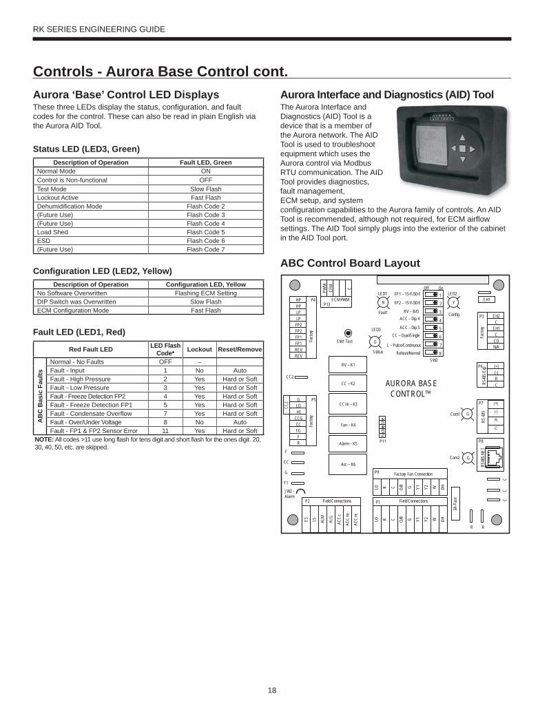
Aurora Interface and Diagnostics (AID) ToolThe Aurora Interface and Diagnostics (AID) Tool is a device that is a member of the Aurora network. The AID Tool is used to troubleshoot equipment which uses the Aurora control via Modbus RTU communication. The AID Tool provides diagnostics, fault management, ECM setup, and system configuration capabilities to the Aurora family of controls. An AID Tool is recommended, although not required, for ECM airflow settings. The AID Tool simply plugs into the exterior of the cabinet in the AID Tool port.
ABC Control Board Layout
Aurora ‘Base’ Control LED DisplaysThese three LEDs display the status, configuration, and fault codes for the control. These can also be read in plain English via the Aurora AID Tool.
Status LED (LED3, Green)Description of Operation Fault LED, Green
Normal Mode ONControl is Non-functional OFFTest Mode Slow FlashLockout Active Fast FlashDehumidification Mode Flash Code 2(Future Use) Flash Code 3(Future Use) Flash Code 4Load Shed Flash Code 5ESD Flash Code 6(Future Use) Flash Code 7
Configuration LED (LED2, Yellow)Description of Operation Configuration LED, Yellow
No Software Overwritten Flashing ECM SettingDIP Switch was Overwritten Slow FlashECM Configuration Mode Fast Flash
Fault LED (LED1, Red)
Red Fault LED LED Flash Code* Lockout Reset/Remove
AB
C B
asic
Fau
lts
Normal - No Faults OFF –Fault - Input 1 No AutoFault - High Pressure 2 Yes Hard or SoftFault - Low Pressure 3 Yes Hard or SoftFault - Freeze Detection FP2 4 Yes Hard or SoftFault - Freeze Detection FP1 5 Yes Hard or SoftFault - Condensate Overflow 7 Yes Hard or SoftFault - Over/Under Voltage 8 No AutoFault - FP1 & FP2 Sensor Error 11 Yes Hard or Soft
NOTE: All codes >11 use long flash for tens digit and short flash for the ones digit. 20, 30, 40, 50, etc. are skipped.
Controls - Aurora Base Control cont.
19
RK SERIES ENGINEERING GUIDE
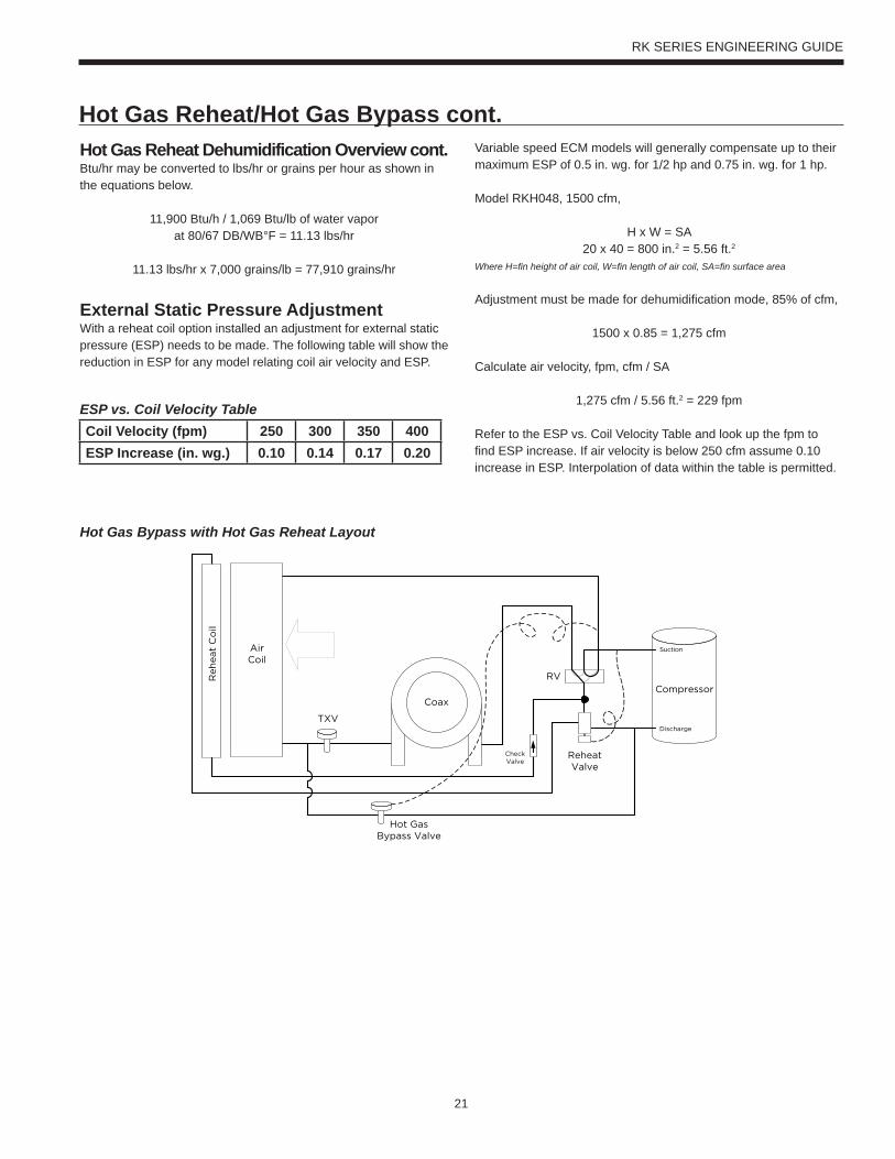
Hot Gas Reheat DescriptionThe refrigerant flows in normal heat pump path in heating and cooling mode. During the Reheat mode, the operation begins with superheated vapor leaving the compressor going through the reheat valve to the reheat air coil. In the reheat coil the high temperature high pressure gas reheats the air exiting the unit to near neutral. Next, the refrigerant exits the reheat coil and passes through a check valve, which is used to prevent refrigerant flow into the reheat coil during normal heating and cooling operation. The refrigerant passes through the check valve and is then diverted to the coaxial heat exchanger by the four way reversing valve. The hot gas enters the coaxial heat exchanger which will condense the gas to a high pressure liquid due to heat being rejected to the loop fluid. The high pressure liquid leaves the coax and enters the inlet of the TXV. After passing through the TXV the low pressure mixture of liquid/vapor refrigerant expands in the air coil evaporating into a low pressure low temperature gas and moves back through the reversing valve and into the compressor suction. The cycle then starts again by compressing the low
pressure low temperature gas into a superheated vapor. A small copper bleed line is located on the reheat/reclaim valve to allow refrigerant that has migrated to the reheat coil to escape.
Hot Gas Bypass DescriptionThe hot gas bypass (HGB) option is designed to limit the minimum evaporating pressure in the cooling mode to prevent the air coil from icing. The HGB valve senses pressure at the outlet of the evaporator by an external equalizer. If the evaporator pressure decreases to 115 psig the HGB valve will begin to open and bypass hot discharge gas into the inlet of the evaporator. The valve will continue to open as needed until it reaches its maximum capacity. Upon a rise of suction pressure, the valve will begin to close back off and normal cooling operation will resume.
Hot Gas Reheat/Hot Gas Bypass
20
RK SERIES ENGINEERING GUIDE
Hot Gas Reheat Dehumidification OverviewDehumidification - The Need for ReheatWith tighter construction and more and more ventilation air being introduced into buildings, there is more need now than ever for proper humidity control. Ensuring dehumidification can provide consistent employee comfort, a reduction in mold liability, a reduction in cooling costs. Reduced humidity also provides an improvement in indoor air quality (IAQ) thru lower humidity levels which can reduce allergen levels, inhibit mold and bacterial growth, and provide an improved computer environment. ASHRAE 90.1 speaks of an acceptable humidity range in all commercial buildings.
Typical Reheat ApplicationsReheat can be used wherever moisture is a problem. Schools, high latent auditorium and theaters, makeup air units*, and computer rooms are typical applications. Although reheat equipped water source heat pumps (wshp’s) can condition limited amounts of outdoor air, the percentage of this outdoor air should never exceed 50% of the return air to the unit limiting the mixed return air temperature to a minimum of 50°F. When cold entering air conditions are anticipated, hot gas bypass option should be considered to prevent air coil freeze up.
*A dedicated outdoor air system (DOAS) should be investigated for 100% outdoor air applications.
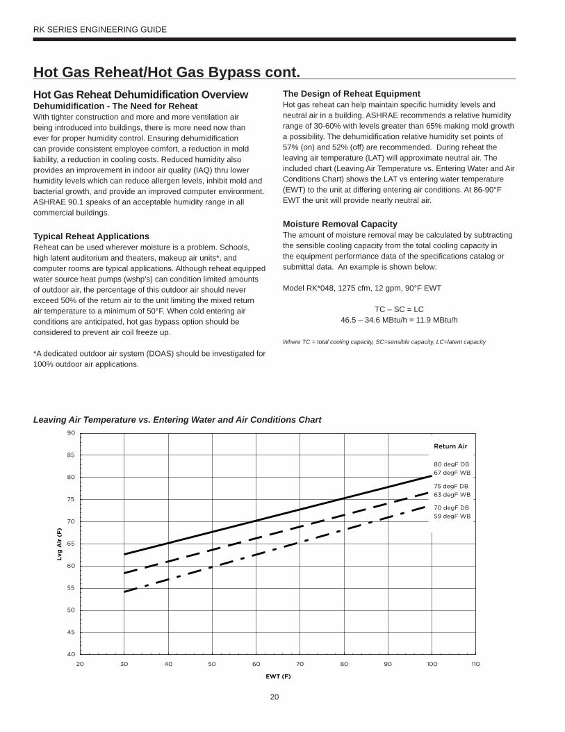
The Design of Reheat EquipmentHot gas reheat can help maintain specific humidity levels and neutral air in a building. ASHRAE recommends a relative humidity range of 30-60% with levels greater than 65% making mold growth a possibility. The dehumidification relative humidity set points of 57% (on) and 52% (off) are recommended. During reheat the leaving air temperature (LAT) will approximate neutral air. The included chart (Leaving Air Temperature vs. Entering Water and Air Conditions Chart) shows the LAT vs entering water temperature (EWT) to the unit at differing entering air conditions. At 86-90°F EWT the unit will provide nearly neutral air.
Moisture Removal CapacityThe amount of moisture removal may be calculated by subtracting the sensible cooling capacity from the total cooling capacity in the equipment performance data of the specifications catalog or submittal data. An example is shown below:
Model RK*048, 1275 cfm, 12 gpm, 90°F EWT
TC – SC = LC46.5 – 34.6 MBtu/h = 11.9 MBtu/h
Where TC = total cooling capacity, SC=sensible capacity, LC=latent capacity
Leaving Air Temperature vs. Entering Water and Air Conditions Chart
Hot Gas Reheat/Hot Gas Bypass cont.
21
RK SERIES ENGINEERING GUIDE
Hot Gas Reheat Dehumidification Overview cont.Btu/hr may be converted to lbs/hr or grains per hour as shown in the equations below.
11,900 Btu/h / 1,069 Btu/lb of water vaporat 80/67 DB/WB°F = 11.13 lbs/hr
11.13 lbs/hr x 7,000 grains/lb = 77,910 grains/hr
External Static Pressure AdjustmentWith a reheat coil option installed an adjustment for external static pressure (ESP) needs to be made. The following table will show the reduction in ESP for any model relating coil air velocity and ESP.
Variable speed ECM models will generally compensate up to their maximum ESP of 0.5 in. wg. for 1/2 hp and 0.75 in. wg. for 1 hp.
Model RKH048, 1500 cfm,
H x W = SA20 x 40 = 800 in.2 = 5.56 ft.2
Where H=fin height of air coil, W=fin length of air coil, SA=fin surface area
Adjustment must be made for dehumidification mode, 85% of cfm,
1500 x 0.85 = 1,275 cfm
Calculate air velocity, fpm, cfm / SA
1,275 cfm / 5.56 ft.2 = 229 fpm
Refer to the ESP vs. Coil Velocity Table and look up the fpm to find ESP increase. If air velocity is below 250 cfm assume 0.10 increase in ESP. Interpolation of data within the table is permitted.
ESP vs. Coil Velocity TableCoil Velocity (fpm) 250 300 350 400ESP Increase (in. wg.) 0.10 0.14 0.17 0.20
Hot Gas Bypass with Hot Gas Reheat Layout
Compressor
ReheatValve
RV
TXV
Suction
Discharge
CheckValve
Coax
AirCoil
Reh
eat
Co
il
Hot GasBypass Valve
Hot Gas Reheat/Hot Gas Bypass cont.
22
RK SERIES ENGINEERING GUIDE
Hot Gas Reheat ControlsThe reheat option is available with the Aurora or FEC 2611 control. The following control schemes are available:
Room wall dehumidistatAn optional room wall dehumidistat that controls the reheat mode thru a 24VAC ‘Hum’ input (On or Off). Setpoint and deadband is determined by the dehumidistat.
Mode of OperationPlease refer to the refrigeration circuit diagram (Hot Gas Reheat - Refrigerant section) and the hot gas reheat wiring schematic.
Heating Mode OperationUpon a call for heating (Y), blower relay is energized immediately, and the compressor contactor will be energized after a 90second delay.
Cooling Mode OperationUpon a call for cooling (Y, O), blower relay and reversing valve coil are energized immediately, and the compressor contactor is energized after a 90 second delay. If there is a call from the de-humidistat or the internal control logic see the humidity sensor has reached set point the blower cfm will be reduced by 15% to increase the unit’s latent capacity.
Dehumidification Mode OperationUpon a call for dehumidification, the blower relay and reversing valve coil are energized immediately, and the compressor contactor will energize after a 90 second delay. The reheat valve coil will energize once the compressor has been operational for 30 seconds.
If a call for space heating is received during reheat operation the compressor will shut down for 5 minutes and the unit will restart in the heating mode. Once the requirement for space heating has been satisfied the unit will shut down for 5 minutes and re-start in reheat mode.
If a call for space cooling is received during reheat operation the reheat valve coil will be disabled until the space cooling requirements have been satisfied. Once the space cooling requirements have been satisfied the reheat valve coil will be energized with out shutting down the compressor.
Dehumidification Set Point(used only with a humidity sensor)The factory default set point for dehumidification is 52% this is field adjustable from 30% to 60%. In addition there is a factory default differential of 5% field adjustable from 5% to 15%. The control will enable re-heat when the space humidity rises above the set point plus the differential. Depending upon the environmental conditions within the building and the operating parameters of the water
source heat pump, the unit may not be capable of maintaining the lower control limit of 30% relative humidity over extended periods of time.
Reheat Operation During Periods of UnoccupancyThis unoccupied set point is useful to reduce energy use in dehumidification. Many system designs greatly reduce or even eliminate fresh air makeup during the unoccupied hours and the need for reheat is lessened. The control logic contains an unoccupied set point that can be used for the unoccupied mode if desired. The factory default for the set point is 60% and is adjustable from 30% to 60%. The unoccupied setback must be enabled either through a building automation system or with a user interface. Factory default for unoccupied setback is off.
Space Humidity High and Low Alarm Limit(building automation system only)The control has a high and low alarm limit that can be enumerated over a building automation system. The factory default set point for these alarm limits is 0% for the low alarm and 100% for the high alarm limit. These limits can be adjusted though a building automation system. Caution should be used in selecting these limits so as not to cause nuisance alarms.
Hot Gas Reheat/Hot Gas Bypass cont.
23
RK SERIES ENGINEERING GUIDE
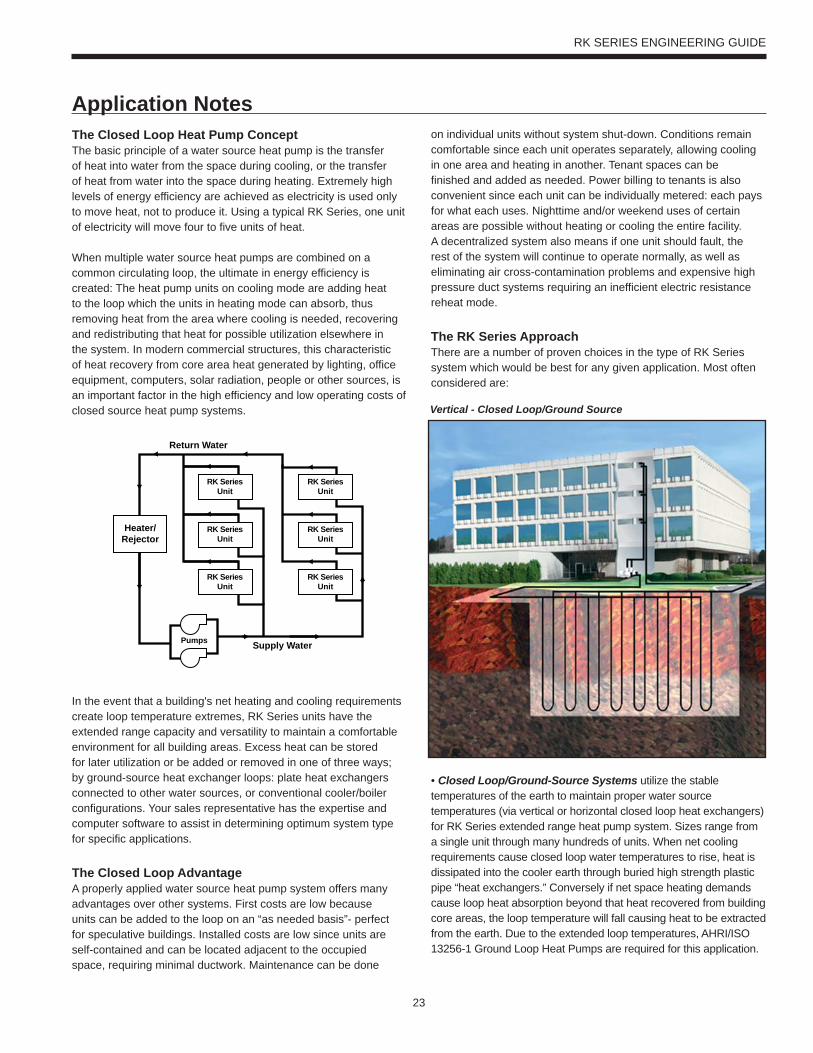
The Closed Loop Heat Pump ConceptThe basic principle of a water source heat pump is the transfer of heat into water from the space during cooling, or the transfer of heat from water into the space during heating. Extremely high levels of energy efficiency are achieved as electricity is used only to move heat, not to produce it. Using a typical RK Series, one unit of electricity will move four to five units of heat.
When multiple water source heat pumps are combined on a common circulating loop, the ultimate in energy efficiency is created: The heat pump units on cooling mode are adding heat to the loop which the units in heating mode can absorb, thus removing heat from the area where cooling is needed, recovering and redistributing that heat for possible utilization elsewhere in the system. In modern commercial structures, this characteristic of heat recovery from core area heat generated by lighting, office equipment, computers, solar radiation, people or other sources, is an important factor in the high efficiency and low operating costs of closed source heat pump systems.
In the event that a building's net heating and cooling requirements create loop temperature extremes, RK Series units have the extended range capacity and versatility to maintain a comfortable environment for all building areas. Excess heat can be stored for later utilization or be added or removed in one of three ways; by ground-source heat exchanger loops: plate heat exchangers connected to other water sources, or conventional cooler/boiler configurations. Your sales representative has the expertise and computer software to assist in determining optimum system type for specific applications.
The Closed Loop AdvantageA properly applied water source heat pump system offers many advantages over other systems. First costs are low because units can be added to the loop on an “as needed basis”- perfect for speculative buildings. Installed costs are low since units are self-contained and can be located adjacent to the occupied space, requiring minimal ductwork. Maintenance can be done
on individual units without system shut-down. Conditions remain comfortable since each unit operates separately, allowing cooling in one area and heating in another. Tenant spaces can be finished and added as needed. Power billing to tenants is also convenient since each unit can be individually metered: each pays for what each uses. Nighttime and/or weekend uses of certain areas are possible without heating or cooling the entire facility. A decentralized system also means if one unit should fault, the rest of the system will continue to operate normally, as well as eliminating air cross-contamination problems and expensive high pressure duct systems requiring an inefficient electric resistance reheat mode.
The RK Series ApproachThere are a number of proven choices in the type of RK Series system which would be best for any given application. Most often considered are:
• Closed Loop/Ground-Source Systems utilize the stable temperatures of the earth to maintain proper water source temperatures (via vertical or horizontal closed loop heat exchangers) for RK Series extended range heat pump system. Sizes range from a single unit through many hundreds of units. When net cooling requirements cause closed loop water temperatures to rise, heat is dissipated into the cooler earth through buried high strength plastic pipe “heat exchangers.” Conversely if net space heating demands cause loop heat absorption beyond that heat recovered from building core areas, the loop temperature will fall causing heat to be extracted from the earth. Due to the extended loop temperatures, AHRI/ISO 13256-1 Ground Loop Heat Pumps are required for this application.
Application Notes
Supply Water
Return Water
Pumps
RK SeriesUnit
RK SeriesUnit
RK SeriesUnit
RK SeriesUnit
RK SeriesUnit
RK SeriesUnit
Heater/Rejector
Vertical - Closed Loop/Ground Source

24
RK SERIES ENGINEERING GUIDE
minimum of 500 sq. ft./ton of surface area at a minimum depth of 8 feet. Your sales representative should be contacted when designs for heating dominated structures are required.
• Closed Loop/Ground Water Plate Heat ExchangerSystems utilize lake, ocean, well water or other water sources to maintain closed loop water temperatures in multi-unit RK Series systems. A plate frame heal exchanger isolates the units from any contaminating effects of the water source, and allows periodic cleaning of the heat exchanger during off peak hours.
Operation and benefits are similar to those for ground-source systems. Due to the extended loop temperatures, AHRI/ISO 13256-1 Ground Loop Heat Pumps are required for this application. Closed loop plate heat exchanger systems are applicable in commercial, marine, or industrial structures where the many benefits of a water source heat pump system are desired, regardless of whether the load is heating or cooling dominated.
Because auxiliary equipment such as a fossil fuel boiler and cooling tower are not required to maintain the loop temperature, operating and maintenance costs are very low.
Ground-source systems are most applicable in residential and light commercial buildings where both heating and cooling are desired, and on larger envelope dominated structures where core heat recovery will not meet overall heating loads. Both vertical and horizontally installed closed-loops can be used. The land space required for the “heat exchangers” is 100-250 sq. ft./ton on vertical (drilled) installations and 750-1500 sq. ft./ton for horizontal (trenched) installations. Closed loop heat exchangers can be located under parking areas or even under the building itself.
On large multi-unit systems, sizing the closed loop heat exchanger to meet only the net heating loads and assisting cooling loads with a closed circuit cooling tower may be the most cost effective choice.
• Closed Loop/Ground-Source Surface Water Systems also utilize the stable temperatures of Surface Water to maintain proper water source temperatures for RK Series extended range heat pump systems. These systems have all of the advantages of horizontal and vertical closed loop systems. Due to the extended loop temperatures, AHRI/ISO 13256-1 Ground Water or Ground Loop Heat Pumps are required for this application.
In cooling dominated structures, the ground-source surface water systems can be very cost effective especially where local building codes require water retention ponds for short term storage of surface run-off. Sizing requirements for the surface water is a
Application Notes cont.
Surface Water - Closed Loop/Ground Source
Plate Heat Exchanger - Closed Loop/Ground Water
25
RK SERIES ENGINEERING GUIDE
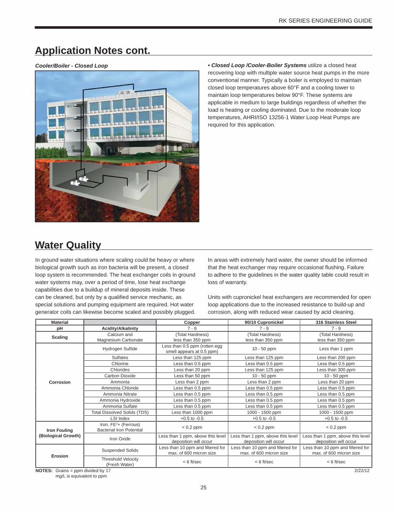
Application Notes cont.• Closed Loop /Cooler-Boiler Systems utilize a closed heat recovering loop with multiple water source heat pumps in the more conventional manner. Typically a boiler is employed to maintain closed loop temperatures above 60°F and a cooling tower to maintain loop temperatures below 90°F. These systems are applicable in medium to large buildings regardless of whether the load is heating or cooling dominated. Due to the moderate loop temperatures, AHRI/ISO 13256-1 Water Loop Heat Pumps are required for this application.
Cooler/Boiler - Closed Loop
In ground water situations where scaling could be heavy or where biological growth such as iron bacteria will be present, a closed loop system is recommended. The heat exchanger coils in ground water systems may, over a period of time, lose heat exchange capabilities due to a buildup of mineral deposits inside. These can be cleaned, but only by a qualified service mechanic, as special solutions and pumping equipment are required. Hot water generator coils can likewise become scaled and possibly plugged.
Water QualityIn areas with extremely hard water, the owner should be informed that the heat exchanger may require occasional flushing. Failure to adhere to the guidelines in the water quality table could result in loss of warranty.
Units with cupronickel heat exchangers are recommended for open loop applications due to the increased resistance to build-up and corrosion, along with reduced wear caused by acid cleaning.
Material Copper 90/10 Cupronickel 316 Stainless SteelpH Acidity/Alkalinity 7 - 9 7 - 9 7 - 9
Scaling Calcium andMagnesium Carbonate
(Total Hardness)less than 350 ppm
(Total Hardness)less than 350 ppm
(Total Hardness)less than 350 ppm
Corrosion
Hydrogen Sulfide Less than 0.5 ppm (rotten egg smell appears at 0.5 ppm) 10 - 50 ppm Less than 1 ppm
Sulfates Less than 125 ppm Less than 125 ppm Less than 200 ppmChlorine Less than 0.5 ppm Less than 0.5 ppm Less than 0.5 ppmChlorides Less than 20 ppm Less than 125 ppm Less than 300 ppm
Carbon Dioxide Less than 50 ppm 10 - 50 ppm 10 - 50 ppmAmmonia Less than 2 ppm Less than 2 ppm Less than 20 ppm
Ammonia Chloride Less than 0.5 ppm Less than 0.5 ppm Less than 0.5 ppmAmmonia Nitrate Less than 0.5 ppm Less than 0.5 ppm Less than 0.5 ppm
Ammonia Hydroxide Less than 0.5 ppm Less than 0.5 ppm Less than 0.5 ppmAmmonia Sulfate Less than 0.5 ppm Less than 0.5 ppm Less than 0.5 ppm
Total Dissolved Solids (TDS) Less than 1000 ppm 1000 - 1500 ppm 1000 - 1500 ppmLSI Index +0.5 to -0.5 +0.5 to -0.5 +0.5 to -0.5
Iron Fouling(Biological Growth)
Iron, FE2+ (Ferrous)Bacterial Iron Potential < 0.2 ppm < 0.2 ppm < 0.2 ppm
Iron Oxide Less than 1 ppm, above this level deposition will occur
Less than 1 ppm, above this level deposition will occur
Less than 1 ppm, above this level deposition will occur
ErosionSuspended Solids Less than 10 ppm and filtered for
max. of 600 micron sizeLess than 10 ppm and filtered for
max. of 600 micron sizeLess than 10 ppm and filtered for
max. of 600 micron sizeThreshold Velocity
(Fresh Water) < 6 ft/sec < 6 ft/sec < 6 ft/sec
NOTES: Grains = ppm divided by 17mg/L is equivalent to ppm
2/22/12
26
RK SERIES ENGINEERING GUIDE
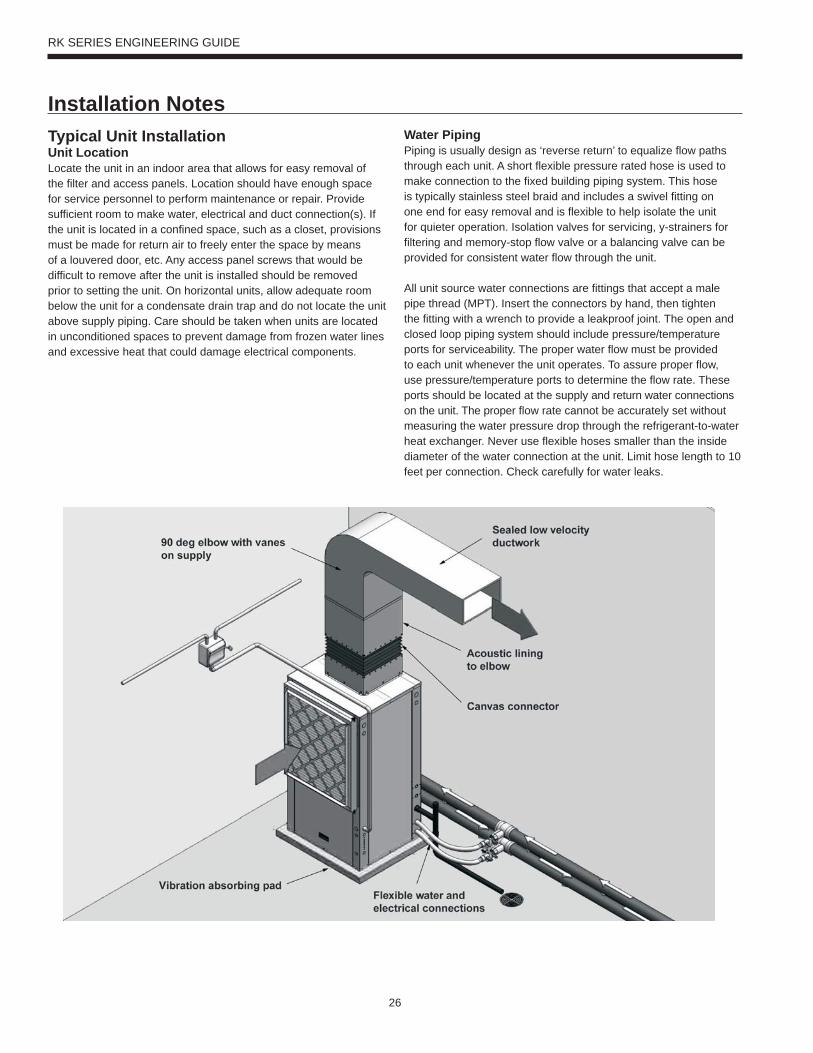
Typical Unit InstallationUnit LocationLocate the unit in an indoor area that allows for easy removal of the filter and access panels. Location should have enough space for service personnel to perform maintenance or repair. Provide sufficient room to make water, electrical and duct connection(s). If the unit is located in a confined space, such as a closet, provisions must be made for return air to freely enter the space by means of a louvered door, etc. Any access panel screws that would be difficult to remove after the unit is installed should be removed prior to setting the unit. On horizontal units, allow adequate room below the unit for a condensate drain trap and do not locate the unit above supply piping. Care should be taken when units are located in unconditioned spaces to prevent damage from frozen water lines and excessive heat that could damage electrical components.
Water PipingPiping is usually design as ‘reverse return’ to equalize flow paths through each unit. A short flexible pressure rated hose is used to make connection to the fixed building piping system. This hose is typically stainless steel braid and includes a swivel fitting on one end for easy removal and is flexible to help isolate the unit for quieter operation. Isolation valves for servicing, y-strainers for filtering and memory-stop flow valve or a balancing valve can be provided for consistent water flow through the unit.
All unit source water connections are fittings that accept a male pipe thread (MPT). Insert the connectors by hand, then tighten the fitting with a wrench to provide a leakproof joint. The open and closed loop piping system should include pressure/temperature ports for serviceability. The proper water flow must be provided to each unit whenever the unit operates. To assure proper flow, use pressure/temperature ports to determine the flow rate. These ports should be located at the supply and return water connections on the unit. The proper flow rate cannot be accurately set without measuring the water pressure drop through the refrigerant-to-water heat exchanger. Never use flexible hoses smaller than the inside diameter of the water connection at the unit. Limit hose length to 10 feet per connection. Check carefully for water leaks.
Installation Notes
27
RK SERIES ENGINEERING GUIDE
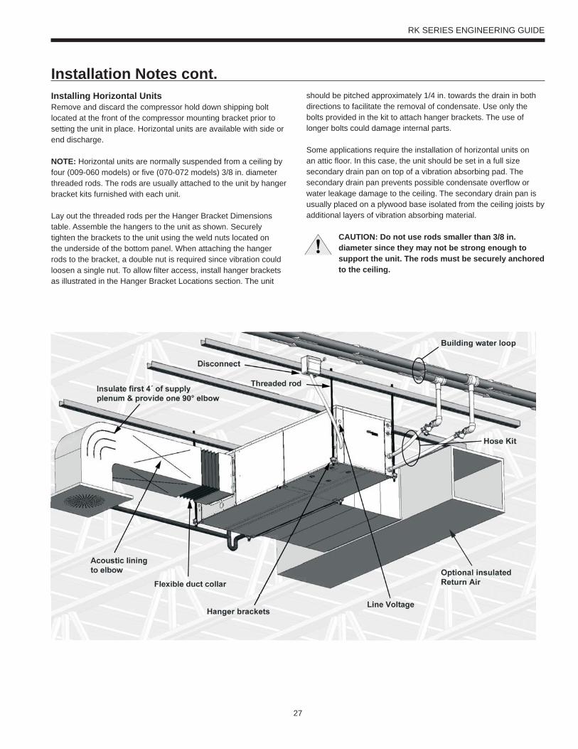
Installing Horizontal UnitsRemove and discard the compressor hold down shipping bolt located at the front of the compressor mounting bracket prior to setting the unit in place. Horizontal units are available with side or end discharge.
NOTE: Horizontal units are normally suspended from a ceiling by four (009-060 models) or five (070-072 models) 3/8 in. diameter threaded rods. The rods are usually attached to the unit by hanger bracket kits furnished with each unit.
Lay out the threaded rods per the Hanger Bracket Dimensions table. Assemble the hangers to the unit as shown. Securely tighten the brackets to the unit using the weld nuts located on the underside of the bottom panel. When attaching the hanger rods to the bracket, a double nut is required since vibration could loosen a single nut. To allow filter access, install hanger brackets as illustrated in the Hanger Bracket Locations section. The unit
should be pitched approximately 1/4 in. towards the drain in both directions to facilitate the removal of condensate. Use only the bolts provided in the kit to attach hanger brackets. The use of longer bolts could damage internal parts.
Some applications require the installation of horizontal units on an attic floor. In this case, the unit should be set in a full size secondary drain pan on top of a vibration absorbing pad. The secondary drain pan prevents possible condensate overflow or water leakage damage to the ceiling. The secondary drain pan is usually placed on a plywood base isolated from the ceiling joists by additional layers of vibration absorbing material.
CAUTION: Do not use rods smaller than 3/8 in. diameter since they may not be strong enough to support the unit. The rods must be securely anchored to the ceiling.
Installation Notes cont.
28
RK SERIES ENGINEERING GUIDE
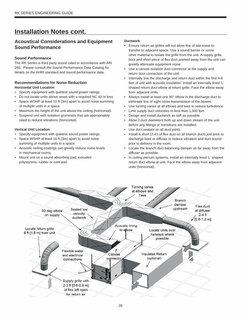
Acoustical Considerations and Equipment Sound Performance
Sound PerformanceThe RK Series is third party sound rated in accordance with ARI 260. Please consult the Sound Performance Data Catalog for details on the AHRI standard and sound performance data.
Recommendations for Noise ReductionHorizontal Unit Location• Specify equipment with quietest sound power ratings• Do not locate units above areas with a required NC 40 or less• Space WSHP at least 10 ft (3m) apart to avoid noise summing
of multiple units in a space.• Maximize the height of the unit above the ceiling (horizontal).• Suspend unit with isolation grommets that are appropriately
rated to reduce vibrations (horizontal).
Vertical Unit Location• Specify equipment with quietest sound power ratings• Space WSHP at least 10 ft (3m) apart to avoid noise
summing of multiple units in a space.• Acoustic ceiling coatings can greatly reduce noise levels
in mechanical rooms.• Mount unit on a sound absorbing pad, extruded
polystyrene, rubber or cork pad.
Ductwork• Ensure return air grilles will not allow line of site noise to
transfer to adjacent space. Use a sound barrier or some other material to isolate the grille from the unit. A supply grille, boot and short piece of flex duct pointed away from the unit can greatly attenuate equipment noise.
• Use a canvas isolation duct connector at the supply and return duct connection of the unit.
• Internally line the discharge and return duct within the first 4-8 feet of unit with acoustic insulation. Install an internally lined ‘L’ shaped return duct elbow at return grille. Face the elbow away from adjacent units.
• Always install at least one 90° elbow in the discharge duct to eliminate line of sight noise transmission of the blower.
• Use turning vanes at all elbows and tees to reduce turbulence.• Limit supply duct velocities to less than 1,000 fpm• Design and install ductwork as stiff as possible• Allow 3 duct diameters both up and down stream of the unit
before any fittings or transitions are installed.• Use duct sealant on all duct joints.• Install a short (2-4’) of flex duct on all branch ducts just prior to
discharge boot or diffuser to reduce vibration and duct sound prior to delivery in the room.
• Locate the branch duct balancing damper as far away from the diffuser as possible.
• In ceiling plenum systems, install an internally lined ‘L’ shaped return duct elbow at unit. Face the elbow away from adjacent units (horizontal).
Installation Notes cont.
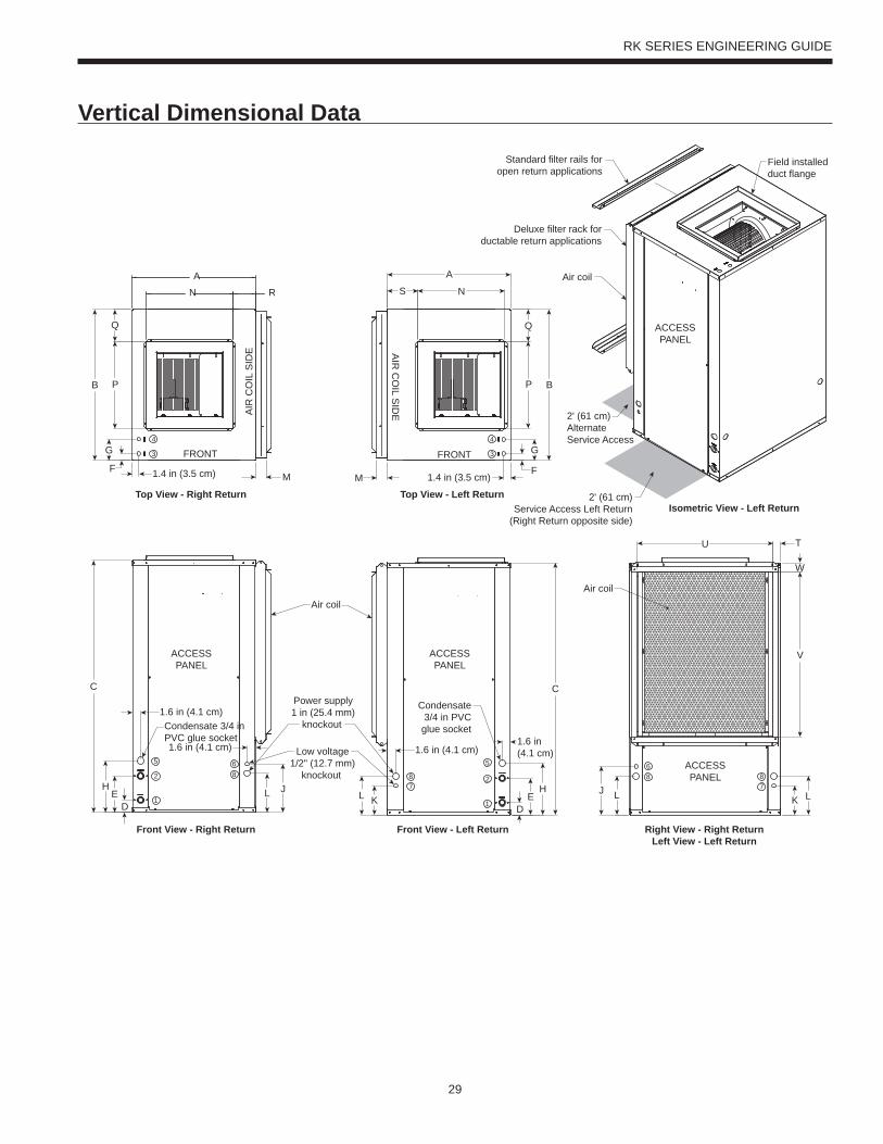
29
RK SERIES ENGINEERING GUIDE
Vertical Dimensional Data
1
28
3
4
ACCESSPANEL
Air coil
AIR
CO
IL S
IDE A
IR C
OIL S
IDE
Air coil
5
Power supply1 in (25.4 mm)
knockout
Low voltage1/2" (12.7 mm)
knockout
Condensate3/4 in PVC
glue socket
FRONT FRONT
Right View - Right ReturnLeft View - Left Return
Air coil
5
Condensate 3/4 inPVC glue socket
1
2
3
4
6
87
87
86
Standard filter rails foropen return applications
Deluxe filter rack forductable return applications
2' (61 cm)Service Access Left Return
(Right Return opposite side)
2' (61 cm)AlternateService Access
Field installedduct flange
ACCESSPANEL
ACCESSPANEL
ACCESSPANEL
Front View - Left Return
Top View - Right Return Top View - Left Return
P
Q
B
RN
A
Front View - Right Return
U T
C
DE
H
F
G
1.4 in (3.5 cm)
1.6 in (4.1 cm)
W
V
1.6 in (4.1 cm)
DE
H
C
1.6 in(4.1 cm)1.6 in (4.1 cm)
L L KJ
1.4 in (3.5 cm)F
G
Q
P B
S N
M M
A
Isometric View - Left Return
K LLJ
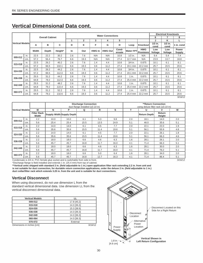
30
RK SERIES ENGINEERING GUIDE
Vertical Dimensional Data cont.
LL
1.8 in.[4.6 cm]
AlternativePowerLocation
Disconnect Located on thisSide for a Right Return
DisconnectLocation
PowerSupply
Vertical Shown inLeft Return Configuration
Vertical Models
Overall Cabinet Water Connections Electrical Knockouts6 7 8
1 2 3 4 5 J K L
A B C D E F G H Loop Knockout 1/2 in. cond
1/2 in. cond 1 in. cond
Width Depth Height* In Out HWG In HWG Out Cond- ensate Water FPT HWG
ProvisionsLow
VoltageLow
VoltagePower Supply
009-012in. 22.5 22.2 30.2 2.6 7.6 N/A N/A 10.8 1/2 in. N/A 9.4 5.4 7.4cm. 57.2 56.4 76.7 6.6 19.3 N/A N/A 27.4 12.7 mm N/A 23.9 13.7 18.8
015-018in. 22.5 26.2 40.2 2.6 7.6 1.4 4.4 10.8 3/4 in. 0.875 10.1 6.1 8.1cm. 57.2 66.5 102.1 6.6 19.3 3.6 11.2 27.4 19.1 mm 22.2 mm 25.7 15.5 20.6
024-030in. 22.5 26.2 44.2 2.6 7.6 1.4 4.4 10.8 3/4 in. 0.875 10.1 6.1 8.1cm. 57.2 66.5 112.3 6.6 19.3 3.6 11.2 27.4 19.1 mm 22.2 mm 25.7 15.5 20.6
036-038in. 25.5 31.2 44.2 2.6 7.6 1.4 4.4 10.8 1 in. 0.875 10.1 6.1 8.1cm. 64.8 79.2 112.3 6.6 19.3 3.6 11.2 27.4 25.4 mm 22.2 mm 25.7 15.5 20.6
042-049in. 25.5 31.2 48.2 2.6 7.6 1.4 4.4 10.8 1 in. 0.875 10.1 6.1 8.1cm. 64.8 79.2 122.4 6.6 19.3 3.6 11.2 27.4 25.4 mm 22.2 mm 25.7 15.5 20.6
060-072in. 25.5 31.2 52.2 2.6 7.6 1.4 4.4 10.8 1 in. 0.875 10.1 6.1 8.1cm. 64.8 79.2 132.6 6.6 19.3 3.6 11.2 27.4 25.4 mm 22.2 mm 25.7 15.5 20.6
3/16/12
Vertical Models
Discharge Connectionduct fl ange installed (±0.10 in)
**Return Connectionusing deluxe fi lter rack (±0.10 in)
M N P Q R S T U V WFilter Rack
Width Supply Width Supply Depth Return Depth Return Height
009-012in. 2.2 10.0 10.0 6.1 5.3 9.8 2.0 18.1 14.0 2.0cm. 5.6 25.4 25.4 15.5 13.5 24.9 5.1 46.0 35.6 5.1
015-018in. 2.2 14.0 14.0 6.1 4.5 7.7 2.0 22.1 22.0 1.9cm. 5.6 35.6 35.6 15.5 11.4 19.6 5.1 56.1 55.9 4.8
024-030in. 2.2 14.0 14.0 6.1 4.5 7.7 2.0 22.1 26.1 1.8cm. 5.6 35.6 35.6 15.5 11.4 19.6 5.1 56.1 66.3 4.6
036-038in. 2.2 18.0 18.0 6.6 4.6 6.3 1.6 28.1 26.1 2.0cm. 5.6 45.7 45.7 16.8 11.7 16.0 4.1 71.4 66.3 5.1
042-049in. 2.2 18.0 18.0 6.6 4.6 6.3 1.6 28.1 30.0 2.0cm. 5.6 45.7 45.7 16.8 11.7 16.0 4.1 71.4 76.2 5.1
060-072in. 2.2 18.0 18.0 6.6 5.0 6.4 1.6 28.1 34.0 2.0cm. 5.6 45.7 45.7 16.8 12.7 16.3 4.1 71.4 86.4 5.1
Condensate is 3/4 in. PVC female glue socket and is switchable from side to front.*Discharge fl ange is fi eld installed and extends 1 in. (25.4 mm) from top of cabinet.**Vertical units shipped with standard 2 in. (fi eld adjustable to 1 in.) open application fi lter rack extending 2.2 in. from unit and is not suitable for duct connection, for ductable return connection applications, order the deluxe 2 in. (fi eld adjustable to 1 in.) duct collar/fi lter rack which extends 3.25 in. from the unit and is suitable for duct connections.
3/16/12
Vertical Models LL009-012 17.8 [45.2]015-018 14.3 [36.3]024-030 15.3 [38.9]036-038 14.3 [36.3]042-049 14.3 [36.3]060-064 14.3 [36.3]070-072 External
Dimensions in inches [cm] 3/16/12
Vertical DisconnectWhen using disconnect, do not use dimension L from the standard vertical dimensional data. Use dimension LL from the vertical disconnect dimensional data.
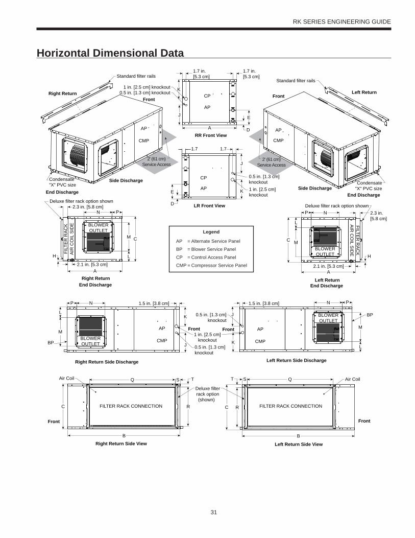
31
RK SERIES ENGINEERING GUIDE
Horizontal Dimensional Data
Right Return End Discharge
Left ReturnEnd Discharge
End Discharge End Discharge
Side DischargeSide Discharge
Right Return Left ReturnFront
Front
CMP CMP
AP AP
Condensate"X" PVC size Condensate
"X" PVC size
RR Front View
BLOWEROUTLET
BLOWEROUTLET
Right Return Side Discharge Left Return Side Discharge
Right Return Side View Left Return Side View
FILTER RACK CONNECTION FILTER RACK CONNECTION
Front Front
Air Coil Air Coil
LR Front View
CP
CP
BLOWEROUTLET
BLOWEROUTLET
Front Front
CMP
AP
CMP
AP
AP
AP
AIR
CO
IL S
IDE A
IR C
OIL S
IDE
0.5 in. [1.3 cm] knockout1 in. [2.5 cm] knockout
1 in. [2.5 cm]knockout
0.5 in. [1.3 cm]knockout
BP
BP
FILT
ER
RA
CK FILTE
R R
AC
K
Standard filter railsStandard filter rails
Deluxe filter rack option shownDeluxe filter rack option shown
Deluxe filterrack option(shown)
BB
C C
L
M
NP
L
M
PN
A
L
M
PN
C
L
MC
A
P N
D
EJ
A
1.7 in.[5.3 cm]
1.7 in.[5.3 cm]
H
2.1 in. [5.3 cm] 2.1 in. [5.3 cm]
H
D
E K
J
K
1.7 1.7
J
K J
K
1.5 in. [3.8 cm]
SQ S QT
R
T
R
2.3 in. [5.8 cm]
Legend
AP = Alternate Service Panel
BP = Blower Service Panel
CP = Control Access Panel
CMP = Compressor Service Panel
2' (61 cm)Service Access
2' (61 cm)Service Access
0.5 in. [1.3 cm]knockout
1.5 in. [3.8 cm]
2.3 in.[5.8 cm]
1 in. [2.5 cm]knockout
0.5 in. [1.3 cm]knockout
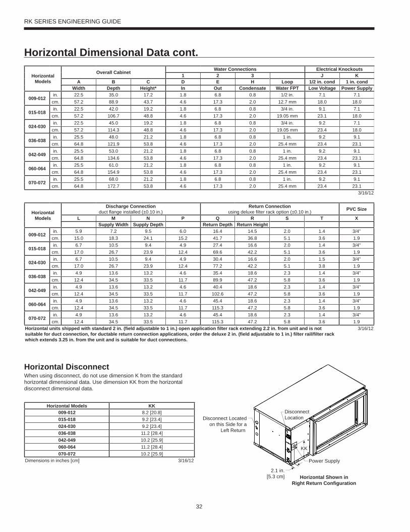
32
RK SERIES ENGINEERING GUIDE
Horizontal Dimensional Data cont.
2.1 in.[5.3 cm]
KK
Disconnect Locatedon this Side for a
Left Return
DisconnectLocation
Power Supply
Horizontal Shown inRight Return Configuration
HorizontalModels
Overall Cabinet Water Connections Electrical Knockouts1 2 3 J K
A B C D E H Loop 1/2 in. cond 1 in. condWidth Depth Height* In Out Condensate Water FPT Low Voltage Power Supply
009-012in. 22.5 35.0 17.2 1.8 6.8 0.8 1/2 in. 7.1 7.1cm. 57.2 88.9 43.7 4.6 17.3 2.0 12.7 mm 18.0 18.0
015-018in. 22.5 42.0 19.2 1.8 6.8 0.8 3/4 in. 9.1 7.1cm. 57.2 106.7 48.8 4.6 17.3 2.0 19.05 mm 23.1 18.0
024-030in. 22.5 45.0 19.2 1.8 6.8 0.8 3/4 in. 9.2 7.1cm. 57.2 114.3 48.8 4.6 17.3 2.0 19.05 mm 23.4 18.0
036-038in. 25.5 48.0 21.2 1.8 6.8 0.8 1 in. 9.2 9.1cm. 64.8 121.9 53.8 4.6 17.3 2.0 25.4 mm 23.4 23.1
042-049in. 25.5 53.0 21.2 1.8 6.8 0.8 1 in. 9.2 9.1cm. 64.8 134.6 53.8 4.6 17.3 2.0 25.4 mm 23.4 23.1
060-064in. 25.5 61.0 21.2 1.8 6.8 0.8 1 in. 9.2 9.1cm. 64.8 154.9 53.8 4.6 17.3 2.0 25.4 mm 23.4 23.1
070-072in. 25.5 68.0 21.2 1.8 6.8 0.8 1 in. 9.2 9.1cm. 64.8 172.7 53.8 4.6 17.3 2.0 25.4 mm 23.4 23.1
3/16/12
HorizontalModels
Discharge Connectionduct fl ange installed (±0.10 in.)
Return Connectionusing deluxe fi lter rack option (±0.10 in.) PVC Size
L M N P Q R S T XSupply Width Supply Depth Return Depth Return Height
009-012in. 5.9 7.2 9.5 6.0 16.4 14.5 2.0 1.4 3/4”cm. 15.0 18.3 24.1 15.2 41.7 36.8 5.1 3.6 1.9
015-018in. 6.7 10.5 9.4 4.9 27.4 16.6 2.0 1.4 3/4”cm. 17.0 26.7 23.9 12.4 69.6 42.2 5.1 3.6 1.9
024-030in. 6.7 10.5 9.4 4.9 30.4 16.6 2.0 1.5 3/4”cm. 17.0 26.7 23.9 12.4 77.2 42.2 5.1 3.8 1.9
036-038in. 4.9 13.6 13.2 4.6 35.4 18.6 2.3 1.4 3/4”cm. 12.4 34.5 33.5 11.7 89.9 47.2 5.8 3.6 1.9
042-049in. 4.9 13.6 13.2 4.6 40.4 18.6 2.3 1.4 3/4”cm. 12.4 34.5 33.5 11.7 102.6 47.2 5.8 3.6 1.9
060-064in. 4.9 13.6 13.2 4.6 45.4 18.6 2.3 1.4 3/4”cm. 12.4 34.5 33.5 11.7 115.3 47.2 5.8 3.6 1.9
070-072in. 4.9 13.6 13.2 4.6 45.4 18.6 2.3 1.4 3/4”cm. 12.4 34.5 33.5 11.7 115.3 47.2 5.8 3.6 1.9
Horizontal units shipped with standard 2 in. (fi eld adjustable to 1 in.) open application fi lter rack extending 2.2 in. from unit and is not suitable for duct connection, for ductable return connection applications, order the deluxe 2 in. (fi eld adjustable to 1 in.) fi lter rail/fi lter rack which extends 3.25 in. from the unit and is suitable for duct connections.
3/16/12
Horizontal Models KK009-012 8.2 [20.8]015-018 9.2 [23.4]024-030 9.2 [23.4]036-038 11.2 [28.4]042-049 10.2 [25.9]060-064 11.2 [28.4]070-072 10.2 [25.9]
Dimensions in inches [cm] 3/16/12
Horizontal DisconnectWhen using disconnect, do not use dimension K from the standard horizontal dimensional data. Use dimension KK from the horizontal disconnect dimensional data.
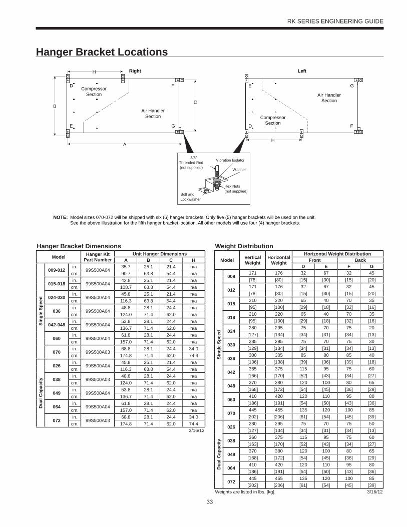
33
RK SERIES ENGINEERING GUIDE
Hanger Bracket Locations
BC
A
H
E
D
G
F
Left
D
E
F
G
Right
Vibration Isolator
Washer
Hex Nuts(not supplied)
Bolt andLockwasher
3/8”Threaded Rod(not supplied)
CompressorSection
CompressorSection
Air HandlerSection
Air HandlerSection
H
NOTE: Model sizes 070-072 will be shipped with six (6) hanger brackets. Only five (5) hanger brackets will be used on the unit. See the above illustration for the fifth hanger bracket location. All other models will use four (4) hanger brackets.
Hanger Bracket DimensionsModel Hanger Kit
Part NumberUnit Hanger Dimensions
A B C H
Sing
le S
peed
009-012in.
99S500A0435.7 25.1 21.4 n/a
cm. 90.7 63.8 54.4 n/a
015-018in.
99S500A0442.8 25.1 21.4 n/a
cm. 108.7 63.8 54.4 n/a
024-030in.
99S500A0445.8 25.1 21.4 n/a
cm. 116.3 63.8 54.4 n/a
036in.
99S500A0448.8 28.1 24.4 n/a
cm. 124.0 71.4 62.0 n/a
042-048in.
99S500A0453.8 28.1 24.4 n/a
cm. 136.7 71.4 62.0 n/a
060in.
99S500A0461.8 28.1 24.4 n/a
cm. 157.0 71.4 62.0 n/a
070in.
99S500A0368.8 28.1 24.4 34.0
cm. 174.8 71.4 62.0 74.4
Dua
l Cap
acity
026in.
99S500A0445.8 25.1 21.4 n/a
cm. 116.3 63.8 54.4 n/a
038in.
99S500A0348.8 28.1 24.4 n/a
cm. 124.0 71.4 62.0 n/a
049in.
99S500A0453.8 28.1 24.4 n/a
cm. 136.7 71.4 62.0 n/a
064in.
99S500A0461.8 28.1 24.4 n/a
cm. 157.0 71.4 62.0 n/a
072in.
99S500A0368.8 28.1 24.4 34.0
cm. 174.8 71.4 62.0 74.43/16/12
Weight Distribution
Model Vertical Weight
HorizontalWeight
Horizontal Weight DistributionFront Back
D E F G
Sing
le S
peed
009171 176 32 67 32 45[78] [80] [15] [30] [15] [20]
012171 176 32 67 32 45[78] [80] [15] [30] [15] [20]
015210 220 65 40 70 35[95] [100] [29] [18] [32] [16]
018210 220 65 40 70 35[95] [100] [29] [18] [32] [16]
024280 295 75 70 75 20[127] [134] [34] [31] [34] [13]
030285 295 75 70 75 30[129] [134] [34] [31] [34] [13]
036300 305 85 80 85 40[136] [138] [39] [36] [39] [18]
042365 375 115 95 75 60[166] [170] [52] [43] [34] [27]
048370 380 120 100 80 65[168] [172] [54] [45] [36] [29]
060410 420 120 110 95 80[186] [191] [54] [50] [43] [36]
070445 455 135 120 100 85[202] [206] [61] [54] [45] [39]
Dua
l Cap
acity
026280 295 75 70 75 50[127] [134] [34] [31] [34] [13]
038360 375 115 95 75 60[163] [170] [52] [43] [34] [27]
049370 380 120 100 80 65[168] [172] [54] [45] [36] [29]
064410 420 120 110 95 80[186] [191] [54] [50] [43] [36]
072445 455 135 120 100 85[202] [206] [61] [54] [45] [39]
Weights are listed in lbs. [kg]. 3/16/12
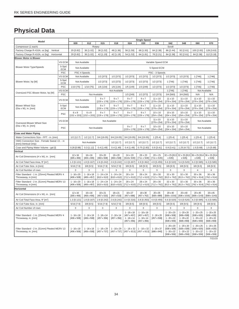
34
RK SERIES ENGINEERING GUIDE
Physical DataModel
Single Speed009 012 015 018 024 030 036 042 048 060 070
Compressor (1 each) Rotary ScrollFactory Charge R-410A, oz [kg] Vertical 29 [0.82] 36 [1.02] 36 [1.02] 48 [1.36] 56 [1.59] 68 [1.93] 84 [2.38] 86 [2.44] 92 [2.61] 100 [2.83] 128 [3.63]
Factory Charge R-410A, oz [kg] Horizontal 29 [0.82] 36 [1.02] 42 [1.19] 42 [1.19] 54 [1.53] 64 [1.81] 78 [2.21] 84 [2.38] 92 [2.61] 84 [2.38] 112 [3.18]Blower Motor & Blower
Blower Motor Type/Speeds
VS ECM Not Available Variable Speed ECM
5-Spd ECM Not Available 5-Speed ECM
PSC PSC 4 Speeds PSC - 3 Speeds
Blower Motor, hp [W]
VS ECM Not Available 1/2 [373] 1/2 [373] 1/2 [373] 1/2 [373] 1/2 [373] 1/2 [373] 1/2 [373] 1 [746] 1 [746]5-Spd ECM Not Available 1/2 [373] 1/2 [373] 1/2 [373] 1/2 [373] 1/2 [373] 1 [746] 1 [746] 1 [746] 1 [746]
PSC 1/10 [75] 1/10 [75] 1/6 [134] 1/6 [134] 1/5 [149] 1/3 [249] 1/2 [373] 1/2 [373] 1/2 [373] 1 [746] 1 [746]
Oversized PSC Blower Motor, hp [W]VS ECM Not Available 1 [746] 1 [746] Not Available
PSC Not Available 1/3 [249] 1/2 [373] 1/2 [373] 3/4 [560] 3/4 [560] N/A N/A
Blower Wheel Size(Dia x W), in. [mm]
VS ECM Not Available 9 x 7[229 x 178]
9 x 7[229 x 178]
9 x 7[229 x 178]
9 x 7[229 x 178]
11 x 10[279 x 254]
11 x 10[279 x 254]
11 x 10[279 x 254]
11 x 10[279 x 254]
11 x 10 [279 x 254]
5-Spd ECM Not Available 9 x 7
[229 x 178]9 x 7
[229 x 178]9 x 7
[229 x 178]9 x 7
[229 x 178]11 x 10
[279 x 254] 11 x 10
[279 x 254] 11 x 10
[279 x 254] 11 x 10
[279 x 254] 11 x 10
[279 x 254]
PSC 6 x 8[152 x 203]
6 x 8[152 x 203]
9 x 7[229 x 178]
9 x 7[229 x 178]
9 x 7[229 x 178]
9 x 7[229 x 178]
10 x 10[254 x 254]
10 x 10[254 x 254]
10 x 10[254 x 254]
11 x 10[279 x 254]
11 x 10[279 x 254]
Oversized Blower Wheel Size(Dia x W), in. [mm]
VS ECM Not Available 11 x 10[279 x 254]
11 x 10[279 x 254]
11 x 10[279 x 254] Not Available
PSC Not Available 9 x 7[229 x 178]
9 x 7[229 x 178]
10 x 10[254 x 254]
10 x 10[254 x 254]
10 x 10[254 x 254] Not Available
Coax and Water PipingWater Connections Size - FPT - in. [mm] 1/2 [12.7] 1/2 [12.7] 3/4 [19.05] 3/4 [19.05] 3/4 [19.05] 3/4 [19.05] 1 [25.4] 1 [25.4] 1 [25.4] 1 [25.4] 1 [25.4]HWG Connection Size - Female Sweat I.D. - in [mm] (Vertical Only) Not Available 1/2 [12.7] 1/2 [12.7] 1/2 [12.7] 1/2 [12.7] 1/2 [12.7] 1/2 [12.7] 1/2 [12.7] 1/2 [12.7]
Coax and Piping Water Volume - gal [l] 0.26 [0.98] 0.3 [1.12] 0.4 [1.49] 0.4 [1.49] 0.4 [1.49] 0.75 [2.83] 0.9 [3.41] 0.9 [3.41] 1.25 [4.72] 1.5 [5.68] 1.5 [5.68]Vertical
Air Coil Dimensions (H x W), in. [mm] 12 x 16[305 x 406]
16 x 16[406 x 406]
19 x 20[483 x 508]
19 x 20[483 x 508]
24 x 20 [610x 508]
28 x 20 [711 x 508]
28 x 25 [711 x 635]
32 x 25 [813 x 635]
32 x 25 [813 x 635]
36 x 25 [914 x 635]
36 x 25 [914 x 635]
Air Coil Total Face Area, ft2 [m2] 1.3 [0.121] 1.8 [0.167] 2.6 [0.242] 2.6 [0.242] 3.3 [0.307] 3.9 [0.362] 4.9 [0.455] 5.6 [0.520] 5.6 [0.520] 6.3 [0.585] 6.3 [0.585]
Air Coil Tube Size, in [mm] 5/16 [7.9] 3/8 [9.5] 5/16 [7.9] 5/16 [7.9] 3/8 [9.5] 3/8 [9.5] 3/8 [9.5] 3/8 [9.5] 3/8 [9.5] 3/8 [9.5] 3/8 [9.5]
Air Coil Number of rows 3 3 3 3 3 3 3 3 3 4 4
Filter Standard - 1 in. [25mm] Pleated MERV 4 Throwaway, in [mm]
1 - 16 x 20[406 x 508]
1 - 16 x 18[406 x 457]
1 - 24 x 24[610 x 610]
1 - 24 x 24[610 x 610]
28 x 24[712 x 610]
28 x 24 [712 x 610]
28 x 30 [712 x 762]
32 x 30[813 x 762]
32 x 30[813 x 762]
30 x 36 [762 x 914]
30 x 36 [762 x 914]
Filter Standard - 2 in. [51mm] Pleated MERV 13 Throwaway, in [mm]
1 - 16 x 20[406 x 508]
1 - 16 x 18[406 x 457]
1 - 24 x 24[610 x 610]
1 - 24 x 24[610 x 610]
28 x 24 [712 x 610]
28 x 24 [712 x 610]
28 x 30 [712 x 762]
32 x 30[813 x 762]
32 x 30[813 x 762]
30 x 36 [762 x 914]
30 x 36 [762 x 914]
Horizontal
Air Coil Dimensions (H x W), in. [mm] 12 x 16[305 x 406]
16 x 16[406 x 406]
18 x 21[457 x 533]
18 x 21[457 x 533]
18 x 27[457 x 686]
18 x 30[457 x 762]
20 x 35[508 x 889]
20 x 40[508 x 1016]
20 x 40[508 x 1016]
20 x 45[508 x 1143]
20 x 45[508 x 1143]
Air Coil Total Face Area, ft2 [m2] 1.3 [0.121] 1.8 [0.167] 2.6 [0.242] 2.6 [0.242] 3.4 [0.316] 3.8 [0.353] 4.9 [0.455] 5.6 [0.520] 5.6 [0.520] 6.3 [0.585] 6.3 [0.585]
Air Coil Tube Size, in. [mm] 5/16 [7.9] 3/8 [9.5] 5/16 [7.9] 5/16 [7.9] 3/8 [9.5] 3/8 [9.5] 3/8 [9.5] 3/8 [9.5] 3/8 [9.5] 3/8 [9.5] 3/8 [9.5]
Air Coil Number of rows 3 3 3 3 3 3 3 3 3 3 3
Filter Standard - 1 in. [25mm] Pleated MERV 4 Throwaway, in. [mm]
1 - 16 x 18[406 x 508]
1 - 16 x 18[406 x 508]
2 - 18 x 14[457 x 356]
2 - 18 x 14[457 x 356]
1 - 18 x 18 [457 x 457] 1 - 18 x 14 [457 x 356]
1 - 18 x 18 [457 x 457] 1 - 18 x 14 [457 x 356]
2 - 18 x 20[457 x 508]
1 - 20 x 20 [508 x 508] 1 - 20 x 22[508 x 559]
1 - 20 x 20 [508 x 508] 1 - 20 x 22 [508 x 559]
1 - 20 x 25 [508 x 635] 1 - 20 x 22[508 x 559]
1 - 20 x 25 [508 x 635] 1 - 20 x 22 [508 x 559]
Filter Standard - 2 in. [51mm] Pleated MERV 13 Throwaway, in. [mm]
1 - 16 x 18[406 x 508]
1 - 16 x 18[406 x 508]
1 - 18 x 29[457 x 737]
1 - 18 x 29[457 x 737]
1 - 18 x 32[457 x 813]
1 - 18 x 32[457 x 813]
1 - 20 x 37[686 x 940]
1 - 20 x 20[508 x 508]1 - 20 x 22[508 x 559]
1 - 20 x 20[508 x 508]1 - 20 x 22[508 x 559]
1 - 20 x 25[508 x 635]1 - 20 x 22[508 x 559]
1 - 20 x 25[508 x 635]1 - 20 x 22[508 x 559]
7/21/15
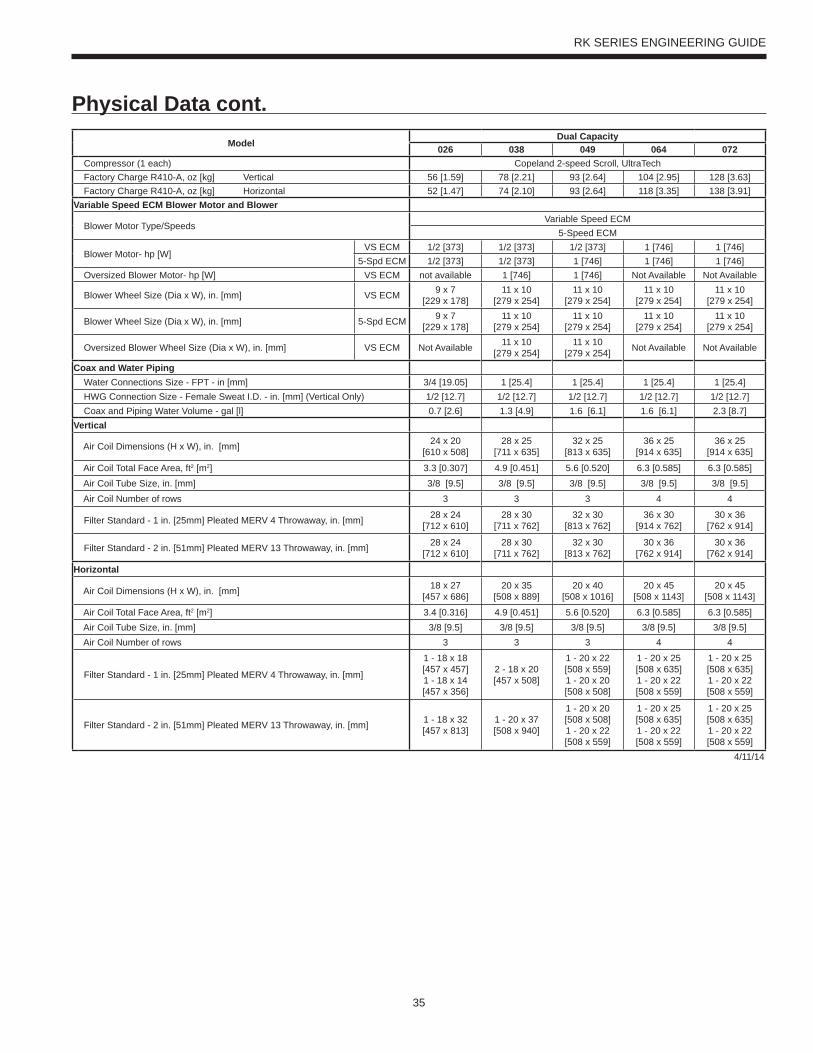
35
RK SERIES ENGINEERING GUIDE
Physical Data cont.Model
Dual Capacity026 038 049 064 072
Compressor (1 each) Copeland 2-speed Scroll, UltraTech Factory Charge R410-A, oz [kg] Vertical 56 [1.59] 78 [2.21] 93 [2.64] 104 [2.95] 128 [3.63] Factory Charge R410-A, oz [kg] Horizontal 52 [1.47] 74 [2.10] 93 [2.64] 118 [3.35] 138 [3.91]Variable Speed ECM Blower Motor and Blower
Blower Motor Type/SpeedsVariable Speed ECM
5-Speed ECM
Blower Motor- hp [W]VS ECM 1/2 [373] 1/2 [373] 1/2 [373] 1 [746] 1 [746]
5-Spd ECM 1/2 [373] 1/2 [373] 1 [746] 1 [746] 1 [746] Oversized Blower Motor- hp [W] VS ECM not available 1 [746] 1 [746] Not Available Not Available
Blower Wheel Size (Dia x W), in. [mm] VS ECM 9 x 7[229 x 178]
11 x 10[279 x 254]
11 x 10[279 x 254]
11 x 10[279 x 254]
11 x 10[279 x 254]
Blower Wheel Size (Dia x W), in. [mm] 5-Spd ECM 9 x 7 [229 x 178]
11 x 10 [279 x 254]
11 x 10 [279 x 254]
11 x 10 [279 x 254]
11 x 10 [279 x 254]
Oversized Blower Wheel Size (Dia x W), in. [mm] VS ECM Not Available 11 x 10[279 x 254]
11 x 10[279 x 254] Not Available Not Available
Coax and Water Piping Water Connections Size - FPT - in [mm] 3/4 [19.05] 1 [25.4] 1 [25.4] 1 [25.4] 1 [25.4] HWG Connection Size - Female Sweat I.D. - in. [mm] (Vertical Only) 1/2 [12.7] 1/2 [12.7] 1/2 [12.7] 1/2 [12.7] 1/2 [12.7] Coax and Piping Water Volume - gal [l] 0.7 [2.6] 1.3 [4.9] 1.6 [6.1] 1.6 [6.1] 2.3 [8.7]Vertical
Air Coil Dimensions (H x W), in. [mm] 24 x 20[610 x 508]
28 x 25[711 x 635]
32 x 25[813 x 635]
36 x 25[914 x 635]
36 x 25[914 x 635]
Air Coil Total Face Area, ft2 [m2] 3.3 [0.307] 4.9 [0.451] 5.6 [0.520] 6.3 [0.585] 6.3 [0.585] Air Coil Tube Size, in. [mm] 3/8 [9.5] 3/8 [9.5] 3/8 [9.5] 3/8 [9.5] 3/8 [9.5] Air Coil Number of rows 3 3 3 4 4
Filter Standard - 1 in. [25mm] Pleated MERV 4 Throwaway, in. [mm] 28 x 24[712 x 610]
28 x 30[711 x 762]
32 x 30[813 x 762]
36 x 30[914 x 762]
30 x 36[762 x 914]
Filter Standard - 2 in. [51mm] Pleated MERV 13 Throwaway, in. [mm] 28 x 24[712 x 610]
28 x 30[711 x 762]
32 x 30[813 x 762]
30 x 36[762 x 914]
30 x 36[762 x 914]
Horizontal
Air Coil Dimensions (H x W), in. [mm] 18 x 27[457 x 686]
20 x 35[508 x 889]
20 x 40[508 x 1016]
20 x 45[508 x 1143]
20 x 45[508 x 1143]
Air Coil Total Face Area, ft2 [m2] 3.4 [0.316] 4.9 [0.451] 5.6 [0.520] 6.3 [0.585] 6.3 [0.585] Air Coil Tube Size, in. [mm] 3/8 [9.5] 3/8 [9.5] 3/8 [9.5] 3/8 [9.5] 3/8 [9.5] Air Coil Number of rows 3 3 3 4 4
Filter Standard - 1 in. [25mm] Pleated MERV 4 Throwaway, in. [mm]
1 - 18 x 18[457 x 457]1 - 18 x 14[457 x 356]
2 - 18 x 20 [457 x 508]
1 - 20 x 22[508 x 559]1 - 20 x 20[508 x 508]
1 - 20 x 25[508 x 635]1 - 20 x 22[508 x 559]
1 - 20 x 25[508 x 635]1 - 20 x 22[508 x 559]
Filter Standard - 2 in. [51mm] Pleated MERV 13 Throwaway, in. [mm] 1 - 18 x 32[457 x 813]
1 - 20 x 37[508 x 940]
1 - 20 x 20[508 x 508]1 - 20 x 22[508 x 559]
1 - 20 x 25[508 x 635]1 - 20 x 22[508 x 559]
1 - 20 x 25[508 x 635]1 - 20 x 22[508 x 559]
4/11/14
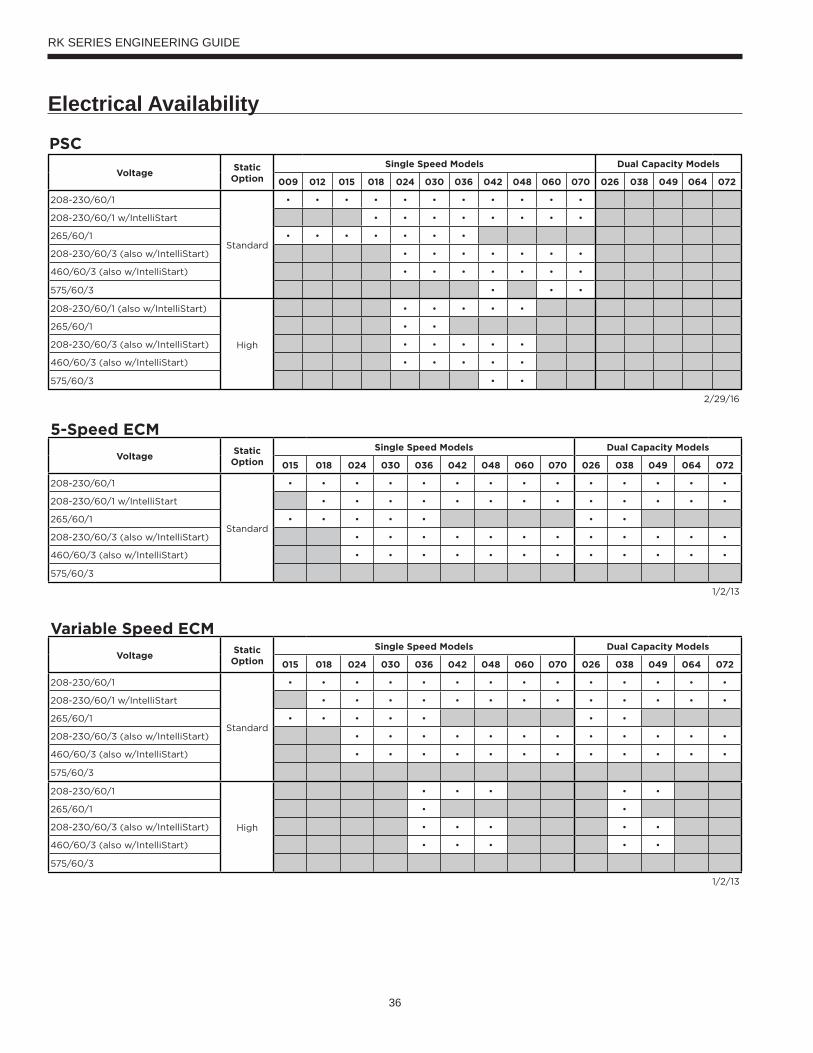
36
RK SERIES ENGINEERING GUIDE
Electrical Availability
PSC
VoltageStatic
Option
Single Speed Models Dual Capacity Models
009 012 015 018 024 030 036 042 048 060 070 026 038 049 064 072
208-230/60/1
Standard
• • • • • • • • • • •
208-230/60/1 w/IntelliStart • • • • • • • •
265/60/1 • • • • • • •
208-230/60/3 (also w/IntelliStart) • • • • • • •
460/60/3 (also w/IntelliStart) • • • • • • •
575/60/3 • • •
208-230/60/1 (also w/IntelliStart)
High
• • • • •
265/60/1 • •
208-230/60/3 (also w/IntelliStart) • • • • •
460/60/3 (also w/IntelliStart) • • • • •
575/60/3 • •
2/29/16
5-Speed ECM
VoltageStatic
Option
Single Speed Models Dual Capacity Models
015 018 024 030 036 042 048 060 070 026 038 049 064 072
208-230/60/1
Standard
• • • • • • • • • • • • • •
208-230/60/1 w/IntelliStart • • • • • • • • • • • • •
265/60/1 • • • • • • •
208-230/60/3 (also w/IntelliStart) • • • • • • • • • • • •
460/60/3 (also w/IntelliStart) • • • • • • • • • • • •
575/60/3
1/2/13
Variable Speed ECM
VoltageStatic
Option
Single Speed Models Dual Capacity Models
015 018 024 030 036 042 048 060 070 026 038 049 064 072
208-230/60/1
Standard
• • • • • • • • • • • • • •
208-230/60/1 w/IntelliStart • • • • • • • • • • • • •
265/60/1 • • • • • • •
208-230/60/3 (also w/IntelliStart) • • • • • • • • • • • •
460/60/3 (also w/IntelliStart) • • • • • • • • • • • •
575/60/3
208-230/60/1
High
• • • • •
265/60/1 • •
208-230/60/3 (also w/IntelliStart) • • • • •
460/60/3 (also w/IntelliStart) • • • • •
575/60/3
1/2/13
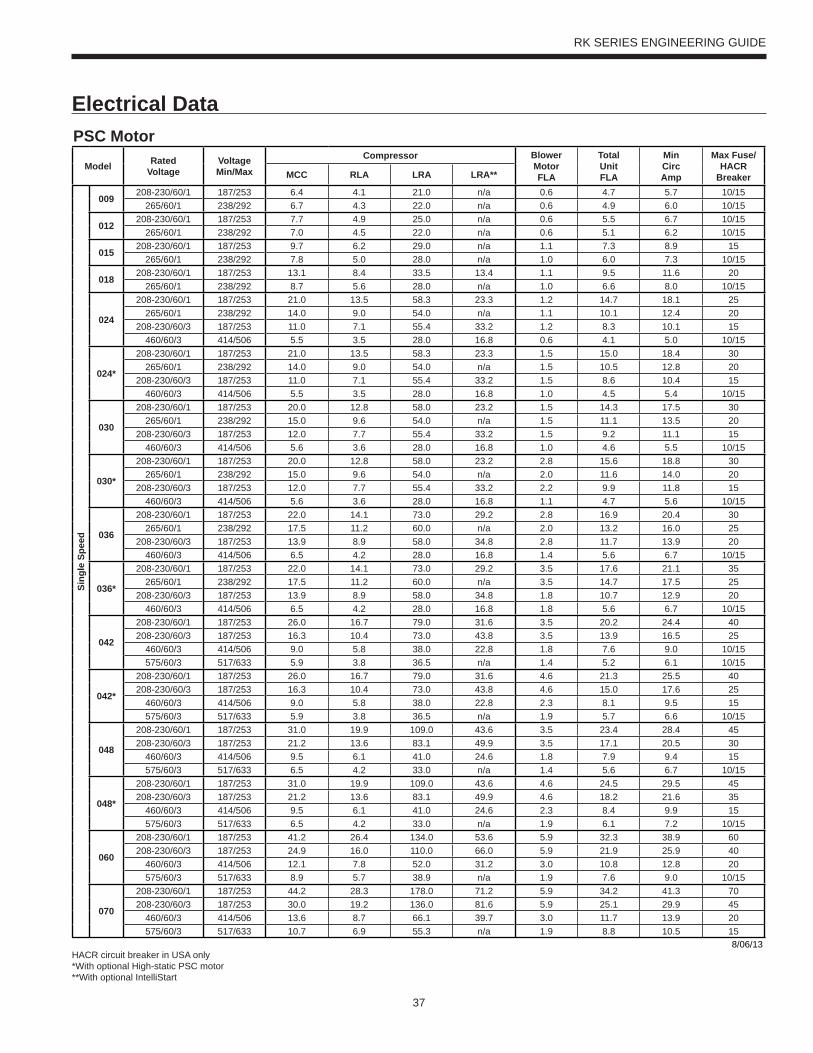
37
RK SERIES ENGINEERING GUIDE
Electrical DataPSC Motor
Model RatedVoltage
VoltageMin/Max
Compressor BlowerMotorFLA
TotalUnitFLA
MinCircAmp
Max Fuse/HACR
BreakerMCC RLA LRA LRA**
Sing
le S
peed
009208-230/60/1 187/253 6.4 4.1 21.0 n/a 0.6 4.7 5.7 10/15
265/60/1 238/292 6.7 4.3 22.0 n/a 0.6 4.9 6.0 10/15
012208-230/60/1 187/253 7.7 4.9 25.0 n/a 0.6 5.5 6.7 10/15
265/60/1 238/292 7.0 4.5 22.0 n/a 0.6 5.1 6.2 10/15
015208-230/60/1 187/253 9.7 6.2 29.0 n/a 1.1 7.3 8.9 15
265/60/1 238/292 7.8 5.0 28.0 n/a 1.0 6.0 7.3 10/15
018208-230/60/1 187/253 13.1 8.4 33.5 13.4 1.1 9.5 11.6 20
265/60/1 238/292 8.7 5.6 28.0 n/a 1.0 6.6 8.0 10/15
024
208-230/60/1 187/253 21.0 13.5 58.3 23.3 1.2 14.7 18.1 25265/60/1 238/292 14.0 9.0 54.0 n/a 1.1 10.1 12.4 20
208-230/60/3 187/253 11.0 7.1 55.4 33.2 1.2 8.3 10.1 15460/60/3 414/506 5.5 3.5 28.0 16.8 0.6 4.1 5.0 10/15
024*
208-230/60/1 187/253 21.0 13.5 58.3 23.3 1.5 15.0 18.4 30265/60/1 238/292 14.0 9.0 54.0 n/a 1.5 10.5 12.8 20
208-230/60/3 187/253 11.0 7.1 55.4 33.2 1.5 8.6 10.4 15460/60/3 414/506 5.5 3.5 28.0 16.8 1.0 4.5 5.4 10/15
030
208-230/60/1 187/253 20.0 12.8 58.0 23.2 1.5 14.3 17.5 30265/60/1 238/292 15.0 9.6 54.0 n/a 1.5 11.1 13.5 20
208-230/60/3 187/253 12.0 7.7 55.4 33.2 1.5 9.2 11.1 15460/60/3 414/506 5.6 3.6 28.0 16.8 1.0 4.6 5.5 10/15
030*
208-230/60/1 187/253 20.0 12.8 58.0 23.2 2.8 15.6 18.8 30265/60/1 238/292 15.0 9.6 54.0 n/a 2.0 11.6 14.0 20
208-230/60/3 187/253 12.0 7.7 55.4 33.2 2.2 9.9 11.8 15460/60/3 414/506 5.6 3.6 28.0 16.8 1.1 4.7 5.6 10/15
036
208-230/60/1 187/253 22.0 14.1 73.0 29.2 2.8 16.9 20.4 30265/60/1 238/292 17.5 11.2 60.0 n/a 2.0 13.2 16.0 25
208-230/60/3 187/253 13.9 8.9 58.0 34.8 2.8 11.7 13.9 20460/60/3 414/506 6.5 4.2 28.0 16.8 1.4 5.6 6.7 10/15
036*
208-230/60/1 187/253 22.0 14.1 73.0 29.2 3.5 17.6 21.1 35265/60/1 238/292 17.5 11.2 60.0 n/a 3.5 14.7 17.5 25
208-230/60/3 187/253 13.9 8.9 58.0 34.8 1.8 10.7 12.9 20460/60/3 414/506 6.5 4.2 28.0 16.8 1.8 5.6 6.7 10/15
042
208-230/60/1 187/253 26.0 16.7 79.0 31.6 3.5 20.2 24.4 40208-230/60/3 187/253 16.3 10.4 73.0 43.8 3.5 13.9 16.5 25
460/60/3 414/506 9.0 5.8 38.0 22.8 1.8 7.6 9.0 10/15575/60/3 517/633 5.9 3.8 36.5 n/a 1.4 5.2 6.1 10/15
042*
208-230/60/1 187/253 26.0 16.7 79.0 31.6 4.6 21.3 25.5 40208-230/60/3 187/253 16.3 10.4 73.0 43.8 4.6 15.0 17.6 25
460/60/3 414/506 9.0 5.8 38.0 22.8 2.3 8.1 9.5 15575/60/3 517/633 5.9 3.8 36.5 n/a 1.9 5.7 6.6 10/15
048
208-230/60/1 187/253 31.0 19.9 109.0 43.6 3.5 23.4 28.4 45208-230/60/3 187/253 21.2 13.6 83.1 49.9 3.5 17.1 20.5 30
460/60/3 414/506 9.5 6.1 41.0 24.6 1.8 7.9 9.4 15575/60/3 517/633 6.5 4.2 33.0 n/a 1.4 5.6 6.7 10/15
048*
208-230/60/1 187/253 31.0 19.9 109.0 43.6 4.6 24.5 29.5 45208-230/60/3 187/253 21.2 13.6 83.1 49.9 4.6 18.2 21.6 35
460/60/3 414/506 9.5 6.1 41.0 24.6 2.3 8.4 9.9 15575/60/3 517/633 6.5 4.2 33.0 n/a 1.9 6.1 7.2 10/15
060
208-230/60/1 187/253 41.2 26.4 134.0 53.6 5.9 32.3 38.9 60208-230/60/3 187/253 24.9 16.0 110.0 66.0 5.9 21.9 25.9 40
460/60/3 414/506 12.1 7.8 52.0 31.2 3.0 10.8 12.8 20575/60/3 517/633 8.9 5.7 38.9 n/a 1.9 7.6 9.0 10/15
070
208-230/60/1 187/253 44.2 28.3 178.0 71.2 5.9 34.2 41.3 70208-230/60/3 187/253 30.0 19.2 136.0 81.6 5.9 25.1 29.9 45
460/60/3 414/506 13.6 8.7 66.1 39.7 3.0 11.7 13.9 20575/60/3 517/633 10.7 6.9 55.3 n/a 1.9 8.8 10.5 15
8/06/13HACR circuit breaker in USA only*With optional High-static PSC motor**With optional IntelliStart
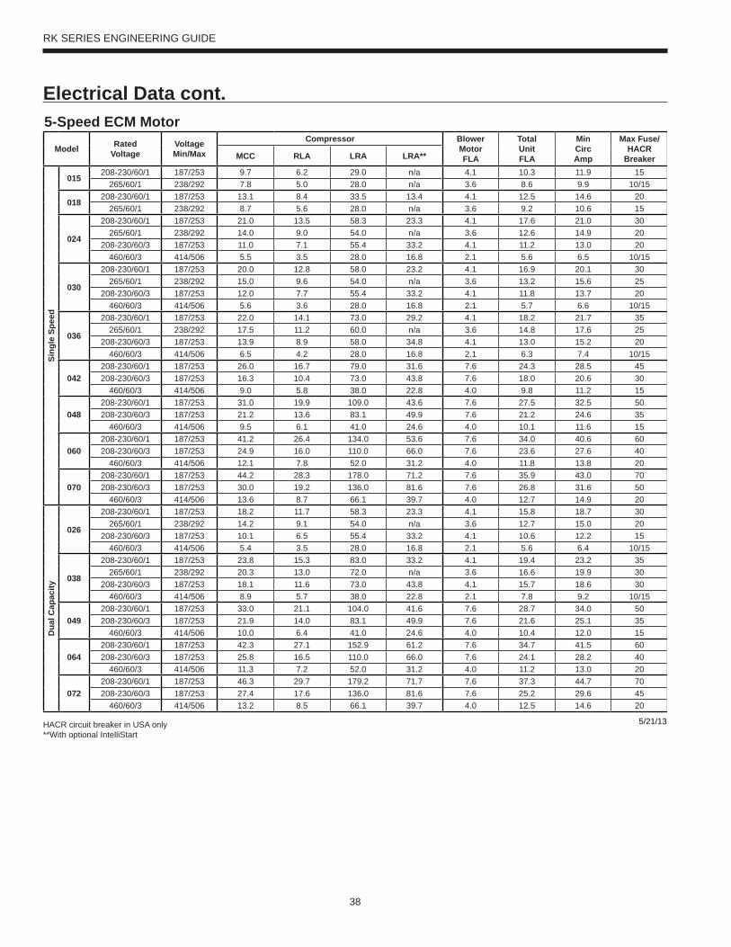
38
RK SERIES ENGINEERING GUIDE
Electrical Data cont.5-Speed ECM Motor
Model RatedVoltage
VoltageMin/Max
Compressor BlowerMotorFLA
TotalUnitFLA
MinCircAmp
Max Fuse/HACR
BreakerMCC RLA LRA LRA**
Sing
le S
peed
015208-230/60/1 187/253 9.7 6.2 29.0 n/a 4.1 10.3 11.9 15
265/60/1 238/292 7.8 5.0 28.0 n/a 3.6 8.6 9.9 10/15
018208-230/60/1 187/253 13.1 8.4 33.5 13.4 4.1 12.5 14.6 20
265/60/1 238/292 8.7 5.6 28.0 n/a 3.6 9.2 10.6 15
024
208-230/60/1 187/253 21.0 13.5 58.3 23.3 4.1 17.6 21.0 30265/60/1 238/292 14.0 9.0 54.0 n/a 3.6 12.6 14.9 20
208-230/60/3 187/253 11.0 7.1 55.4 33.2 4.1 11.2 13.0 20460/60/3 414/506 5.5 3.5 28.0 16.8 2.1 5.6 6.5 10/15
030
208-230/60/1 187/253 20.0 12.8 58.0 23.2 4.1 16.9 20.1 30265/60/1 238/292 15.0 9.6 54.0 n/a 3.6 13.2 15.6 25
208-230/60/3 187/253 12.0 7.7 55.4 33.2 4.1 11.8 13.7 20460/60/3 414/506 5.6 3.6 28.0 16.8 2.1 5.7 6.6 10/15
036
208-230/60/1 187/253 22.0 14.1 73.0 29.2 4.1 18.2 21.7 35265/60/1 238/292 17.5 11.2 60.0 n/a 3.6 14.8 17.6 25
208-230/60/3 187/253 13.9 8.9 58.0 34.8 4.1 13.0 15.2 20460/60/3 414/506 6.5 4.2 28.0 16.8 2.1 6.3 7.4 10/15
042208-230/60/1 187/253 26.0 16.7 79.0 31.6 7.6 24.3 28.5 45208-230/60/3 187/253 16.3 10.4 73.0 43.8 7.6 18.0 20.6 30
460/60/3 414/506 9.0 5.8 38.0 22.8 4.0 9.8 11.2 15
048208-230/60/1 187/253 31.0 19.9 109.0 43.6 7.6 27.5 32.5 50208-230/60/3 187/253 21.2 13.6 83.1 49.9 7.6 21.2 24.6 35
460/60/3 414/506 9.5 6.1 41.0 24.6 4.0 10.1 11.6 15
060208-230/60/1 187/253 41.2 26.4 134.0 53.6 7.6 34.0 40.6 60208-230/60/3 187/253 24.9 16.0 110.0 66.0 7.6 23.6 27.6 40
460/60/3 414/506 12.1 7.8 52.0 31.2 4.0 11.8 13.8 20
070208-230/60/1 187/253 44.2 28.3 178.0 71.2 7.6 35.9 43.0 70208-230/60/3 187/253 30.0 19.2 136.0 81.6 7.6 26.8 31.6 50
460/60/3 414/506 13.6 8.7 66.1 39.7 4.0 12.7 14.9 20
Dua
l Cap
acity
026
208-230/60/1 187/253 18.2 11.7 58.3 23.3 4.1 15.8 18.7 30265/60/1 238/292 14.2 9.1 54.0 n/a 3.6 12.7 15.0 20
208-230/60/3 187/253 10.1 6.5 55.4 33.2 4.1 10.6 12.2 15460/60/3 414/506 5.4 3.5 28.0 16.8 2.1 5.6 6.4 10/15
038
208-230/60/1 187/253 23.8 15.3 83.0 33.2 4.1 19.4 23.2 35265/60/1 238/292 20.3 13.0 72.0 n/a 3.6 16.6 19.9 30
208-230/60/3 187/253 18.1 11.6 73.0 43.8 4.1 15.7 18.6 30460/60/3 414/506 8.9 5.7 38.0 22.8 2.1 7.8 9.2 10/15
049208-230/60/1 187/253 33.0 21.1 104.0 41.6 7.6 28.7 34.0 50208-230/60/3 187/253 21.9 14.0 83.1 49.9 7.6 21.6 25.1 35
460/60/3 414/506 10.0 6.4 41.0 24.6 4.0 10.4 12.0 15
064208-230/60/1 187/253 42.3 27.1 152.9 61.2 7.6 34.7 41.5 60208-230/60/3 187/253 25.8 16.5 110.0 66.0 7.6 24.1 28.2 40
460/60/3 414/506 11.3 7.2 52.0 31.2 4.0 11.2 13.0 20
072208-230/60/1 187/253 46.3 29.7 179.2 71.7 7.6 37.3 44.7 70208-230/60/3 187/253 27.4 17.6 136.0 81.6 7.6 25.2 29.6 45
460/60/3 414/506 13.2 8.5 66.1 39.7 4.0 12.5 14.6 20
5/21/13HACR circuit breaker in USA only**With optional IntelliStart
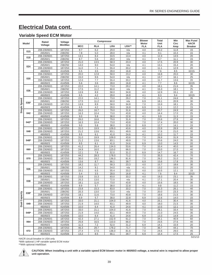
39
RK SERIES ENGINEERING GUIDE
Electrical Data cont.
CAUTION: When installing a unit with a variable speed ECM blower motor in 460/60/3 voltage, a neutral wire is required to allow proper unit operation.
Variable Speed ECM Motor
Model RatedVoltage
VoltageMin/Max
Compressor BlowerMotorFLA
TotalUnitFLA
MinCircAmp
Max Fuse/HACR
BreakerMCC RLA LRA LRA**
Sing
le S
peed
015 208-230/60/1 187/253 9.7 6.2 29.0 n/a 4.0 10.2 11.8 15265/60/1 238/292 7.8 5.0 28.0 n/a 4.1 9.1 10.4 15
018 208-230/60/1 187/253 13.1 8.4 33.5 13.4 4.0 12.4 14.5 20265/60/1 238/292 8.7 5.6 28.0 n/a 4.1 9.7 11.1 15
024
208-230/60/1 187/253 21.0 13.5 58.3 23.3 4.0 17.5 20.9 30265/60/1 238/292 14.0 9.0 54.0 n/a 4.1 13.1 15.4 20
208-230/60/3 187/253 11.0 7.1 55.4 33.2 4.0 11.1 12.9 20460/60/3 414/506 5.5 3.5 28.0 16.8 4.1 7.6 8.5 10/15
030
208-230/60/1 187/253 20.0 12.8 58.0 23.2 4.0 16.8 20.0 30265/60/1 238/292 15.0 9.6 54.0 n/a 4.1 13.7 16.1 25
208-230/60/3 187/253 12.0 7.7 55.4 33.2 4.0 11.7 13.6 20460/60/3 414/506 5.6 3.6 28.0 16.8 4.1 7.7 8.6 10/15
036
208-230/60/1 187/253 22.0 14.1 73.0 29.2 4.0 18.1 21.6 35265/60/1 238/292 17.5 11.2 60.0 n/a 4.1 15.3 18.1 25
208-230/60/3 187/253 13.9 8.9 58.0 34.8 4.0 12.9 15.1 20460/60/3 414/506 6.5 4.2 28.0 16.8 4.1 8.3 9.4 10/15
036*
208-230/60/1 187/253 22.0 14.1 73.0 29.2 7.0 21.1 24.6 35265/60/1 238/292 17.5 11.2 60.0 n/a 6.9 18.1 20.9 30
208-230/60/3 187/253 13.9 8.9 58.0 34.8 7.0 15.9 18.1 25460/60/3 414/506 6.5 4.2 28.0 16.8 6.9 11.1 12.2 15
042208-230/60/1 187/253 26.0 16.7 79.0 31.6 4.0 20.7 24.9 40208-230/60/3 187/253 16.3 10.4 73.0 43.8 4.0 14.4 17.0 25
460/60/3 414/506 9.0 5.8 38.0 22.8 4.1 9.9 11.3 15
042*208-230/60/1 187/253 26.0 16.6 79.0 31.6 7.0 23.6 27.8 40208-230/60/3 187/253 16.3 10.4 73.0 43.8 7.0 17.4 20.0 30
460/60/3 414/506 9.0 5.8 38.0 22.8 6.9 12.7 14.1 15
048208-230/60/1 187/253 31.0 19.9 109.0 43.6 4.0 23.9 28.9 45208-230/60/3 187/253 21.2 13.6 83.1 49.9 4.0 17.6 21.0 30
460/60/3 414/506 9.5 6.1 41.0 24.6 4.1 10.2 11.7 15
048*208-230/60/1 187/253 31.0 19.9 109.0 43.6 7.0 26.9 31.9 50208-230/60/3 187/253 21.2 13.6 83.1 49.9 7.0 20.6 24.0 35
460/60/3 414/506 9.5 6.1 41.0 24.6 6.9 13.0 14.5 20
060208-230/60/1 187/253 41.2 26.4 134.0 53.6 7.0 33.4 40.0 60208-230/60/3 187/253 24.9 16.0 110.0 66.0 7.0 23.0 27.0 40
460/60/3 414/506 12.1 7.8 52.0 31.2 6.9 14.7 16.7 20
070208-230/60/1 187/253 44.2 28.3 178.0 71.2 7.0 35.3 42.4 70208-230/60/3 187/253 30.0 19.2 136.0 81.6 7.0 26.2 31.0 50
460/60/3 414/506 13.6 8.7 66.1 39.7 6.9 15.6 17.8 25
Dua
l Cap
acity
026
208-230/60/1 187/253 18.2 11.7 58.3 23.3 4.0 15.7 18.6 30265/60/1 238/292 14.2 9.1 54.0 n/a 4.1 13.2 15.5 20
208-230/60/3 187/253 10.1 6.5 55.4 33.2 4.0 10.5 12.1 15460/60/3 414/506 5.4 3.5 28.0 16.8 4.1 7.6 8.4 10/15
038
208-230/60/1 187/253 23.8 15.3 83.0 33.2 4.0 19.3 23.1 35265/60/1 238/292 20.3 13.0 72.0 n/a 4.1 17.1 20.4 30
208-230/60/3 187/253 18.1 11.6 73.0 43.8 4.0 15.6 18.5 30460/60/3 414/506 8.9 5.7 38.0 22.8 4.1 9.8 11.2 15
038*
208-230/60/1 187/253 23.8 15.3 83.0 33.2 7.0 22.3 26.1 40265/60/1 238/292 20.3 13.0 72.0 n/a 7.0 20.0 23.3 35
208-230/60/3 187/253 18.1 11.6 73.0 43.8 7.0 18.6 21.5 30460/60/3 414/506 8.9 5.7 38.0 22.8 6.9 12.6 14.0 15
049208-230/60/1 187/253 33.0 21.1 104.0 41.6 4.0 25.1 30.4 50208-230/60/3 187/253 21.9 14.0 83.1 49.9 4.0 18.0 21.5 35
460/60/3 414/506 10.0 6.4 41.0 24.6 4.1 10.5 12.1 15
049*208-230/60/1 187/253 33.0 21.1 104.0 41.6 7.0 28.1 33.4 50208-230/60/3 187/253 21.9 14.0 83.1 49.9 7.0 21.0 24.5 35
460/60/3 414/506 10.0 6.4 41.0 24.6 6.9 13.3 14.9 20
064208-230/60/1 187/253 42.3 27.1 152.9 61.2 7.0 34.1 40.9 60208-230/60/3 187/253 25.8 16.5 110.0 66.0 7.0 23.5 27.6 40
460/60/3 414/506 11.3 7.2 52.0 31.2 6.9 14.1 15.9 20
072208-230/60/1 187/253 46.3 29.7 179.2 71.7 7.0 36.7 44.1 70208-230/60/3 187/253 27.4 17.6 136.0 81.6 7.0 24.6 29.0 45
460/60/3 414/506 13.2 8.5 66.1 39.7 6.9 15.4 17.5 255/21/13
HACR circuit breaker in USA only*With optional 1 HP variable speed ECM motor**With optional IntelliStart
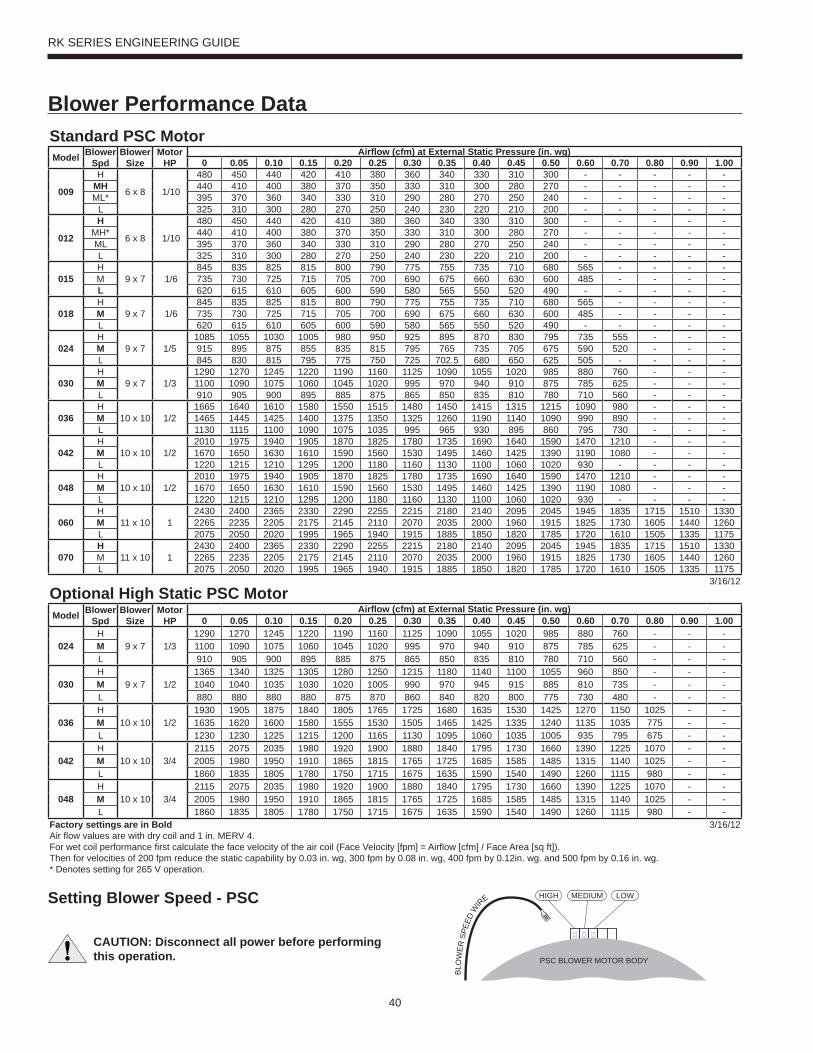
40
RK SERIES ENGINEERING GUIDE
Blower Performance Data
PSC BLOWER MOTOR BODY
HIGH LOWMEDIUM
BLO
WER
SPE
ED W
IRE
Standard PSC MotorModel Blower
SpdBlower
SizeMotor
HPAirfl ow (cfm) at External Static Pressure (in. wg)
0 0.05 0.10 0.15 0.20 0.25 0.30 0.35 0.40 0.45 0.50 0.60 0.70 0.80 0.90 1.00
009
H
6 x 8 1/10
480 450 440 420 410 380 360 340 330 310 300 - - - - -MH 440 410 400 380 370 350 330 310 300 280 270 - - - - -ML* 395 370 360 340 330 310 290 280 270 250 240 - - - - -
L 325 310 300 280 270 250 240 230 220 210 200 - - - - -
012
H
6 x 8 1/10
480 450 440 420 410 380 360 340 330 310 300 - - - - -MH* 440 410 400 380 370 350 330 310 300 280 270 - - - - -ML 395 370 360 340 330 310 290 280 270 250 240 - - - - -L 325 310 300 280 270 250 240 230 220 210 200 - - - - -
015H
9 x 7 1/6845 835 825 815 800 790 775 755 735 710 680 565 - - - -
M 735 730 725 715 705 700 690 675 660 630 600 485 - - - -L 620 615 610 605 600 590 580 565 550 520 490 - - - - -
018H
9 x 7 1/6845 835 825 815 800 790 775 755 735 710 680 565 - - - -
M 735 730 725 715 705 700 690 675 660 630 600 485 - - - -L 620 615 610 605 600 590 580 565 550 520 490 - - - - -
024H
9 x 7 1/51085 1055 1030 1005 980 950 925 895 870 830 795 735 555 - - -
M 915 895 875 855 835 815 795 765 735 705 675 590 520 - - -L 845 830 815 795 775 750 725 702.5 680 650 625 505 - - - -
030H
9 x 7 1/31290 1270 1245 1220 1190 1160 1125 1090 1055 1020 985 880 760 - - -
M 1100 1090 1075 1060 1045 1020 995 970 940 910 875 785 625 - - -L 910 905 900 895 885 875 865 850 835 810 780 710 560 - - -
036H
10 x 10 1/21665 1640 1610 1580 1550 1515 1480 1450 1415 1315 1215 1090 980 - - -
M 1465 1445 1425 1400 1375 1350 1325 1260 1190 1140 1090 990 890 - - -L 1130 1115 1100 1090 1075 1035 995 965 930 895 860 795 730 - - -
042H
10 x 10 1/22010 1975 1940 1905 1870 1825 1780 1735 1690 1640 1590 1470 1210 - - -
M 1670 1650 1630 1610 1590 1560 1530 1495 1460 1425 1390 1190 1080 - - -L 1220 1215 1210 1295 1200 1180 1160 1130 1100 1060 1020 930 - - - -
048H
10 x 10 1/22010 1975 1940 1905 1870 1825 1780 1735 1690 1640 1590 1470 1210 - - -
M 1670 1650 1630 1610 1590 1560 1530 1495 1460 1425 1390 1190 1080 - - -L 1220 1215 1210 1295 1200 1180 1160 1130 1100 1060 1020 930 - - - -
060H
11 x 10 12430 2400 2365 2330 2290 2255 2215 2180 2140 2095 2045 1945 1835 1715 1510 1330
M 2265 2235 2205 2175 2145 2110 2070 2035 2000 1960 1915 1825 1730 1605 1440 1260L 2075 2050 2020 1995 1965 1940 1915 1885 1850 1820 1785 1720 1610 1505 1335 1175
070H
11 x 10 12430 2400 2365 2330 2290 2255 2215 2180 2140 2095 2045 1945 1835 1715 1510 1330
M 2265 2235 2205 2175 2145 2110 2070 2035 2000 1960 1915 1825 1730 1605 1440 1260L 2075 2050 2020 1995 1965 1940 1915 1885 1850 1820 1785 1720 1610 1505 1335 1175
3/16/12Optional High Static PSC MotorModel Blower
SpdBlower
SizeMotor
HPAirfl ow (cfm) at External Static Pressure (in. wg)
0 0.05 0.10 0.15 0.20 0.25 0.30 0.35 0.40 0.45 0.50 0.60 0.70 0.80 0.90 1.00
024H
9 x 7 1/31290 1270 1245 1220 1190 1160 1125 1090 1055 1020 985 880 760 - - -
M 1100 1090 1075 1060 1045 1020 995 970 940 910 875 785 625 - - -L 910 905 900 895 885 875 865 850 835 810 780 710 560 - - -
030H
9 x 7 1/21365 1340 1325 1305 1280 1250 1215 1180 1140 1100 1055 960 850 - - -
M 1040 1040 1035 1030 1020 1005 990 970 945 915 885 810 735 - - -L 880 880 880 880 875 870 860 840 820 800 775 730 480 - - -
036H
10 x 10 1/21930 1905 1875 1840 1805 1765 1725 1680 1635 1530 1425 1270 1150 1025 - -
M 1635 1620 1600 1580 1555 1530 1505 1465 1425 1335 1240 1135 1035 775 - -L 1230 1230 1225 1215 1200 1165 1130 1095 1060 1035 1005 935 795 675 - -
042H
10 x 10 3/42115 2075 2035 1980 1920 1900 1880 1840 1795 1730 1660 1390 1225 1070 - -
M 2005 1980 1950 1910 1865 1815 1765 1725 1685 1585 1485 1315 1140 1025 - -L 1860 1835 1805 1780 1750 1715 1675 1635 1590 1540 1490 1260 1115 980 - -
048H
10 x 10 3/42115 2075 2035 1980 1920 1900 1880 1840 1795 1730 1660 1390 1225 1070 - -
M 2005 1980 1950 1910 1865 1815 1765 1725 1685 1585 1485 1315 1140 1025 - -L 1860 1835 1805 1780 1750 1715 1675 1635 1590 1540 1490 1260 1115 980 - -
Factory settings are in BoldAir fl ow values are with dry coil and 1 in. MERV 4.For wet coil performance fi rst calculate the face velocity of the air coil (Face Velocity [fpm] = Airfl ow [cfm] / Face Area [sq ft]). Then for velocities of 200 fpm reduce the static capability by 0.03 in. wg, 300 fpm by 0.08 in. wg, 400 fpm by 0.12in. wg. and 500 fpm by 0.16 in. wg.* Denotes setting for 265 V operation.
3/16/12
Setting Blower Speed - PSC
CAUTION: Disconnect all power before performing this operation.
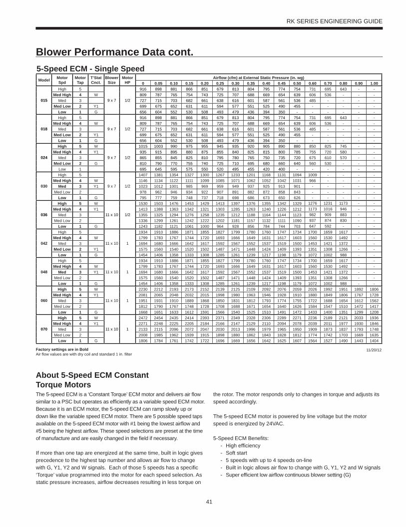
41
RK SERIES ENGINEERING GUIDE
Blower Performance Data cont.
About 5-Speed ECM ConstantTorque MotorsThe 5-speed ECM is a ‘Constant Torque’ ECM motor and delivers air fl ow similar to a PSC but operates as effi ciently as a variable speed ECM motor. Because it is an ECM motor, the 5-speed ECM can ramp slowly up or down like the variable speed ECM motor. There are 5 possible speed taps available on the 5-speed ECM motor with #1 being the lowest airfl ow and #5 being the highest airfl ow. These speed selections are preset at the time of manufacture and are easily changed in the fi eld if necessary.
If more than one tap are energized at the same time, built in logic gives precedence to the highest tap number and allows air fl ow to change with G, Y1, Y2 and W signals. Each of those 5 speeds has a specifi c ‘Torque’ value programmed into the motor for each speed selection. As static pressure increases, airfl ow decreases resulting in less torque on
the rotor. The motor responds only to changes in torque and adjusts its speed accordingly.
The 5-speed ECM motor is powered by line voltage but the motor speed is energized by 24VAC.
5-Speed ECM Benefi ts: - High effi ciency - Soft start - 5 speeds with up to 4 speeds on-line - Built in logic allows air fl ow to change with G, Y1, Y2 and W signals - Super effi cient low airfl ow continuous blower setting (G)
5-Speed ECM - Single SpeedModel Motor
SpdMotor Tap
T’StatCnct.
Blower Size
Motor HP
Airfl ow (cfm) at External Static Pressure (in. wg)0 0.05 0.10 0.15 0.20 0.25 0.30 0.35 0.40 0.45 0.50 0.60 0.70 0.80 0.90 1.00
015
High 5
9 x 7 1/2
916 898 881 866 851 679 813 804 795 774 754 731 695 643 - -Med High 4 W 809 787 765 754 743 725 707 688 669 654 639 606 536 - - -
Med 3 727 715 703 682 661 638 616 601 587 561 536 485 - - - -Med Low 2 Y1 699 675 652 631 611 594 577 551 525 490 455 - - - - -
Low 1 G 656 604 552 530 508 493 479 436 394 350 - - - - - -
018
High 5
9 x 7 1/2
916 898 881 866 851 679 813 804 795 774 754 731 695 643 - -Med High 4 W 809 787 765 754 743 725 707 688 669 654 639 606 536 - - -
Med 3 727 715 703 682 661 638 616 601 587 561 536 485 - - - -Med Low 2 Y1 699 675 652 631 611 594 577 551 525 490 455 - - - - -
Low 1 G 656 604 552 530 508 493 479 436 394 350 - - - - - -
024
High 5 W
9 x 7 1/2
1015 1003 990 975 955 945 935 920 905 890 880 850 825 745 - -Med High 4 Y1 935 915 895 880 875 855 840 825 815 800 785 755 720 580 - -
Med 3 865 855 845 825 810 795 780 765 750 735 720 675 610 570 - -Med Low 2 G 810 790 770 755 740 725 710 695 680 660 640 560 530 - - -
Low 1 695 645 595 575 550 520 495 455 420 400 - - - - - -
030
High 5
9 x 7 1/2
1407 1381 1354 1327 1300 1267 1233 1201 1168 1131 1094 1009 - - - -Med High 4 W 1146 1134 1122 1111 1099 1085 1071 1062 1052 1042 1031 966 - - - -
Med 3 Y1 1023 1012 1001 985 969 959 949 937 925 913 901 - - - - -Med Low 2 978 962 946 934 922 907 891 882 872 858 843 - - - - -
Low 1 G 795 777 759 748 737 718 698 686 673 650 626 - - - - -
036
High 5 W
11 x 10 1/2
1530 1503 1476 1453 1429 1413 1397 1376 1355 1342 1329 1276 1231 1173 - -Med High 4 Y1 1413 1388 1363 1342 1321 1303 1285 1263 1240 1226 1212 1173 1016 946 - -
Med 3 1355 1325 1294 1276 1258 1235 1212 1188 1164 1144 1123 982 909 883 - -Med Low 2 1336 1299 1261 1242 1222 1202 1181 1157 1132 1111 1090 937 874 830 - -
Low 1 G 1243 1182 1121 1061 1000 964 928 856 784 744 703 647 592 - - -
042
High 5
11 x 10 1
1934 1910 1886 1871 1855 1827 1799 1780 1760 1747 1734 1700 1659 1617 - -Med High 4 W 1799 1783 1767 1744 1720 1693 1666 1649 1631 1617 1603 1560 1530 1492 - -
Med 3 1694 1680 1666 1642 1617 1592 1567 1552 1537 1519 1500 1453 1421 1372 - -Med Low 2 Y1 1575 1560 1540 1520 1502 1487 1471 1448 1424 1409 1393 1351 1308 1266 - -
Low 1 G 1454 1406 1358 1333 1308 1285 1261 1239 1217 1198 1179 1072 1002 988 - -
048
High 5
11 x 10 1
1934 1910 1886 1871 1855 1827 1799 1780 1760 1747 1734 1700 1659 1617 - -Med High 4 W 1799 1783 1767 1744 1720 1693 1666 1649 1631 1617 1603 1560 1530 1492 - -
Med 3 Y1 1694 1680 1666 1642 1617 1592 1567 1552 1537 1519 1500 1453 1421 1372 - -Med Low 2 1575 1560 1540 1520 1502 1487 1471 1448 1424 1409 1393 1351 1308 1266 - -
Low 1 G 1454 1406 1358 1333 1308 1285 1261 1239 1217 1198 1179 1072 1002 988 - -
060
High 5 W
11 x 10 1
2230 2212 2193 2173 2152 2139 2125 2109 2092 2076 2059 2026 1992 1951 1892 1806Med High 4 Y1 2081 2065 2048 2032 2015 1998 1980 1963 1946 1928 1910 1880 1849 1806 1767 1728
Med 3 1951 1931 1910 1889 1868 1850 1831 1812 1793 1774 1755 1722 1688 1654 1612 1562Med Low 2 1812 1790 1767 1748 1728 1708 1688 1671 1654 1640 1626 1584 1547 1510 1472 1417
Low 1 G 1668 1651 1633 1612 1591 1566 1540 1525 1510 1491 1472 1433 1400 1351 1299 1208
070
High 5 W
11 x 10 1
2472 2454 2435 2414 2393 2371 2349 2328 2306 2289 2271 2236 2189 2121 2033 1936Med High 4 Y1 2271 2248 2225 2205 2184 2166 2147 2129 2110 2094 2078 2039 2011 1977 1930 1846
Med 3 2133 2115 2096 2072 2047 2030 2013 1996 1979 1965 1950 1909 1873 1837 1793 1748Med Low 2 2008 1985 1962 1939 1915 1898 1880 1862 1843 1828 1812 1774 1742 1703 1669 1635
Low 1 G 1806 1784 1761 1742 1722 1696 1669 1656 1642 1625 1607 1564 1527 1490 1443 1404
11/20/12Factory settings are in BoldAir fl ow values are with dry coil and standard 1 in. fi lter
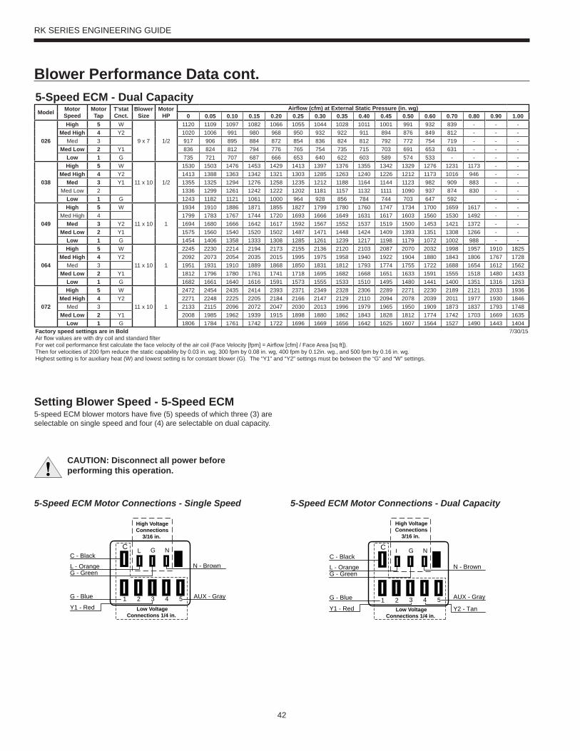
42
RK SERIES ENGINEERING GUIDE
Blower Performance Data cont.
L G NC
High VoltageConnections
3/16 in.
1 2 3 4 5G - Blue
Y1 - Red
AUX - Gray
C - Black
L - OrangeG - Green
N - Brown
Low VoltageConnections 1/4 in.
L G NC
1 2 3 4 5 AUX - GrayG - Blue
Y1 - Red Y2 - Tan
C - Black
L - OrangeG - Green
N - Brown
High VoltageConnections
3/16 in.
Low VoltageConnections 1/4 in.
CAUTION: Disconnect all power before performing this operation.
Setting Blower Speed - 5-Speed ECM5-speed ECM blower motors have fi ve (5) speeds of which three (3) are selectable on single speed and four (4) are selectable on dual capacity.
5-Speed ECM Motor Connections - Single Speed 5-Speed ECM Motor Connections - Dual Capacity
5-Speed ECM - Dual CapacityModel Motor
SpeedMotor Tap
T’statCnct.
Blower Size
Motor HP
Airfl ow (cfm) at External Static Pressure (in. wg)0 0.05 0.10 0.15 0.20 0.25 0.30 0.35 0.40 0.45 0.50 0.60 0.70 0.80 0.90 1.00
026
High 5 W
9 x 7 1/2
1120 1109 1097 1082 1066 1055 1044 1028 1011 1001 991 932 839 - - -Med High 4 Y2 1020 1006 991 980 968 950 932 922 911 894 876 849 812 - - -
Med 3 917 906 895 884 872 854 836 824 812 792 772 754 719 - - -Med Low 2 Y1 836 824 812 794 776 765 754 735 715 703 691 653 631 - - -
Low 1 G 735 721 707 687 666 653 640 622 603 589 574 533 - - - -
038
High 5 W
11 x 10 1/2
1530 1503 1476 1453 1429 1413 1397 1376 1355 1342 1329 1276 1231 1173 - -Med High 4 Y2 1413 1388 1363 1342 1321 1303 1285 1263 1240 1226 1212 1173 1016 946 - -
Med 3 Y1 1355 1325 1294 1276 1258 1235 1212 1188 1164 1144 1123 982 909 883 - -Med Low 2 1336 1299 1261 1242 1222 1202 1181 1157 1132 1111 1090 937 874 830 - -
Low 1 G 1243 1182 1121 1061 1000 964 928 856 784 744 703 647 592 - -
049
High 5 W
11 x 10 1
1934 1910 1886 1871 1855 1827 1799 1780 1760 1747 1734 1700 1659 1617 - -Med High 4 1799 1783 1767 1744 1720 1693 1666 1649 1631 1617 1603 1560 1530 1492 - -
Med 3 Y2 1694 1680 1666 1642 1617 1592 1567 1552 1537 1519 1500 1453 1421 1372 - -Med Low 2 Y1 1575 1560 1540 1520 1502 1487 1471 1448 1424 1409 1393 1351 1308 1266 - -
Low 1 G 1454 1406 1358 1333 1308 1285 1261 1239 1217 1198 1179 1072 1002 988 - -
064
High 5 W
11 x 10 1
2245 2230 2214 2194 2173 2155 2136 2120 2103 2087 2070 2032 1998 1957 1910 1825Med High 4 Y2 2092 2073 2054 2035 2015 1995 1975 1958 1940 1922 1904 1880 1843 1806 1767 1728
Med 3 1951 1931 1910 1889 1868 1850 1831 1812 1793 1774 1755 1722 1688 1654 1612 1562Med Low 2 Y1 1812 1796 1780 1761 1741 1718 1695 1682 1668 1651 1633 1591 1555 1518 1480 1433
Low 1 G 1682 1661 1640 1616 1591 1573 1555 1533 1510 1495 1480 1441 1400 1351 1316 1263
072
High 5 W
11 x 10 1
2472 2454 2435 2414 2393 2371 2349 2328 2306 2289 2271 2230 2189 2121 2033 1936Med High 4 Y2 2271 2248 2225 2205 2184 2166 2147 2129 2110 2094 2078 2039 2011 1977 1930 1846
Med 3 2133 2115 2096 2072 2047 2030 2013 1996 1979 1965 1950 1909 1873 1837 1793 1748Med Low 2 Y1 2008 1985 1962 1939 1915 1898 1880 1862 1843 1828 1812 1774 1742 1703 1669 1635
Low 1 G 1806 1784 1761 1742 1722 1696 1669 1656 1642 1625 1607 1564 1527 1490 1443 1404Factory speed settings are in BoldAir fl ow values are with dry coil and standard fi lterFor wet coil performance fi rst calculate the face velocity of the air coil (Face Velocity [fpm] = Airfl ow [cfm] / Face Area [sq ft]). Then for velocities of 200 fpm reduce the static capability by 0.03 in. wg, 300 fpm by 0.08 in. wg, 400 fpm by 0.12in. wg., and 500 fpm by 0.16 in. wg.Highest setting is for auxiliary heat (W) and lowest setting is for constant blower (G). The “Y1” and “Y2” settings must be between the “G” and “W” settings.
7/30/15
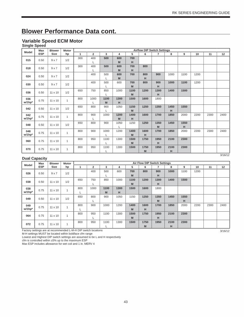
43
RK SERIES ENGINEERING GUIDE
Blower Performance Data cont.Variable Speed ECM MotorSingle Speed
Model MaxESP
Blower Size
Motor hp
Airfl ow DIP Switch Settings1 2 3 4 5 6 7 8 9 10 11 12
015 0.50 9 x 7 1/2300 400 500 600 700
L M H
018 0.50 9 x 7 1/2300 400 500 600 700 800
L M H
024 0.50 9 x 7 1/2400 500 600 700 800 900 1000 1100 1200
L M H
030 0.50 9 x 7 1/2400 500 600 700 800 900 1000 1100 1200
L M H
036 0.50 11 x 10 1/2650 750 850 1000 1100 1200 1300 1400 1500
L M H036
w/1hp* 0.75 11 x 10 1800 1000 1100 1300 1500 1600 1800
L M H
042 0.50 11 x 10 1/2650 800 900 1050 1150 1250 1350 1450 1550
L M H042
w/1hp* 0.75 11 x 10 1800 900 1000 1200 1400 1600 1700 1850 2000 2200 2300 2400
L M H
048 0.50 11 x 10 1/2650 800 900 1050 1150 1250 1350 1450 1550
L M H048
w/1hp* 0.75 11 x 10 1800 900 1000 1200 1400 1600 1700 1850 2000 2200 2300 2400
L M H
060 0.75 11 x 10 1800 950 1100 1300 1500 1750 1950 2100 2300
L M H
070 0.75 11 x 10 1800 950 1100 1300 1500 1750 1950 2100 2300
L M H3/16/12
Dual CapacityModel Max
ESPBlower
SizeMotor
hpAir Flow DIP Switch Settings
1 2 3 4 5 6 7 8 9 10 11 12
026 0.50 9 x 7 1/2400 500 600 700 800 900 1000 1100 1200
L M H
038 0.50 11 x 10 1/2650 750 850 1000 1100 1200 1300 1400 1500
L M H038
w/1hp* 0.75 11 x 10 1800 1000 1100 1300 1500 1600 1800
L M H
049 0.50 11 x 10 1/2650 800 900 1050 1150 1250 1350 1450 1550
L M H049
w/1hp* 0.75 11 x 10 1800 900 1000 1200 1400 1600 1700 1850 2000 2200 2300 2400
L M H
064 0.75 11 x 10 1800 950 1100 1300 1500 1750 1950 2100 2300
L M H
072 0.75 11 x 10 1800 950 1100 1300 1500 1750 1950 2100 2300
L M HFactory settings are at recommended L-M-H DIP switch locationsM-H settings MUST be located within boldface cfm rangeLowest and Highest DIP switch settings are assumed to be L and H respectivelycfm is controlled within ±5% up to the maximum ESPMax ESP includes allowance for wet coil and 1 in. MERV 4
3/16/12
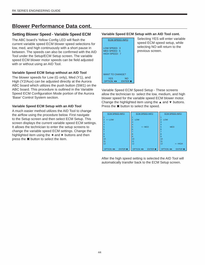
44
RK SERIES ENGINEERING GUIDE
Blower Performance Data cont.
The ABC board’s Yellow Confi g LED will fl ash the current variable speed ECM blower speed selections for low, med, and high continuously with a short pause in between. The speeds can also be confi rmed with the AID Tool under the Setup/ECM Setup screen. The variable speed ECM blower motor speeds can be fi eld adjusted with or without using an AID Tool.
Variable Speed ECM Setup without an AID ToolThe blower speeds for Low (G only), Med (Y1), and High (Y2/Aux) can be adjusted directly at the Aurora ABC board which utilizes the push button (SW1) on the ABC board. This procedure is outlined in the Variable Speed ECM Confi guration Mode portion of the Aurora ‘Base’ Control System section.
Variable Speed ECM Setup with an AID ToolA much easier method utilizes the AID Tool to change the airfl ow using the procedure below. First navigate to the Setup screen and then select ECM Setup. This screen displays the current variable speed ECM settings. It allows the technician to enter the setup screens to change the variable speed ECM settings. Change the highlighted item using the ◀ and ▶ buttons and then press the ◙ button to select the item.
Setting Blower Speed - Variable Speed ECM
Variable Speed ECM Speed Setup - These screens allow the technician to select the low, medium, and high blower speed for the variable speed ECM blower motor. Change the highlighted item using the ▲ and ▼ buttons. Press the ◙ button to select the speed.
After the high speed setting is selected the AID Tool will automatically transfer back to the ECM Setup screen.
Variable Speed ECM Setup with an AID Tool cont.Selecting YES will enter variable speed ECM speed setup, while selecting NO will return to the previous screen.
ECM SPEED INFO
LOW SPEED: 3MED SPEED: 5HIGH SPEED: 7
WANT TO CHANGE?
YESOPTION ◀▶
NOENTER ◙
ECM SPEED INFO
12 <– LOW3456789101112
OPTION ◀▶ ENTER ◙
ECM SPEED INFO
12 LOW345 <– MED6789101112
OPTION ◀▶ ENTER ◙
ECM SPEED INFO
12 LOW345 MED6789101112 <– HIGH
OPTION ◀▶ ENTER ◙
45
RK SERIES ENGINEERING GUIDE
Selection ExampleTo achieve optimal performance, proper selection of each heat pump is essential. A building load program should be used to determine the heating and cooling load of each zone. A computer software selection program can then be used to develop an accurate and complete heat pump schedule.
While a computer software program is the easiest and most accurate method to size and select equipment, however, selection can still be accomplished manually using this manual and the following selection procedure. Sizing so that the actual sensible capacity of the equipment will satisfy the sensible capacity of the zone is the recommended method for best results.
Boiler/Tower ApplicationTypical boiler/tower application will result in entering water temperatures of 60-90°F with 70°F for heating and 90°F for cooling. Water to refrigerant insulation option would not be required. Flow rates are 2.5 to 3 gpm per ton with 2.5 gpm per ton often representing an economical design point.
Geothermal ApplicationTypical geothermal application can result in a wide entering water temperature range of 30-100°F. Typically minimum heating entering water temperatures can range from 30 to 50°F depending upon loop type and geographical location. Cooling performance should be calculated using a maximum loop temperature of 100°F in most loop applications. Water flow is typically 2.5 to 3 gpm per ton with 3 gpm per ton recommended with the more extreme loop temperatures. PLEASE NOTE THAT WATER COIL INSULATION OPTION SHOULD BE SELECTED WHEN ENTERING WATER TEMPERATURES ARE EXPECTED TO BE BELOW 45-50°F.
Geothermal Selection ExampleStep 1: Determine the actual heating and cooling loads at the desired dry bulb and wet bulb conditions.
Step 2: Obtain the following design parameters: Entering water temperature, water flow rate in gpm, airflow in cfm, water flow pressure drop and design wet and dry bulb temperatures. Airflow, cfm, should be between 300 and 450 cfm per ton. Unit water pressure drop should be kept as close as possible to each other to make water balancing easier. Go to the appropriate tables and find the proper indicated water flow and water temperature.
Step 3: Select a unit based on total and sensible cooling conditions. Select a unit which is closest to, but no larger than, the actual cooling load.
Step 4: Enter tables at the design water flow and water temperature. Read the total and sensible cooling capacities (NOTE: interpolation is permissible, extrapolation is not).
Step 5: Read the heating capacity. If it exceeds the design criteria it is acceptable. It is quite normal for water source heat pumps to be selected on cooling capacity only since the heating output is usually greater than the cooling capacity.
Step 6: Determine the correction factors associated with the variable factors of dry bulb and wet bulb. Corrected Total Cooling = tabulated total cooling x wetbulb correction.Corrected Sensible Cooling = tabulated sensible cooling x wet/dry bulb correction.
Step 7: Compare the corrected capacities to the load requirements. Normally if the capacities are within 10% of the loads, the equipment is acceptable. It is better to undersize than oversize, as undersizing improves humidity control, reduces sound levels and extends the life of the equipment.
Step 8: When complete, calculate water temperature rise and assess the selection. If the units selected are not within 10% of the load calculations, then review what effect changing the gpm, water temperature and/or airflow and air temperature would have on the corrected capacities. If the desired capacity cannot be achieved, select the next larger or smaller unit and repeat the procedure. Remember, when in doubt, undersize slightly for best performance.
Example Equipment Selection - Cooling1. Load Determination:Assume we have determined that the appropriate cooling load at the desired dry bulb 80°F and wet bulb 65°F conditions is as follows:Total Cooling ..............................................................57,500 Btu/hSensible Cooling........................................................38,400 Btu/hEntering Air Temp ..........................75°F Dry Bulb / 65°F Wet Bulb
2. Design Conditions:Similarly, we have also obtained the following design parameters:Entering Water Temp ..............................................................90°FWater Flow (Based upon 10°F rise in temp.) 15.0 gpmAirflow Required ...................................... 1,900 cfm @ 0.2 in. wg.
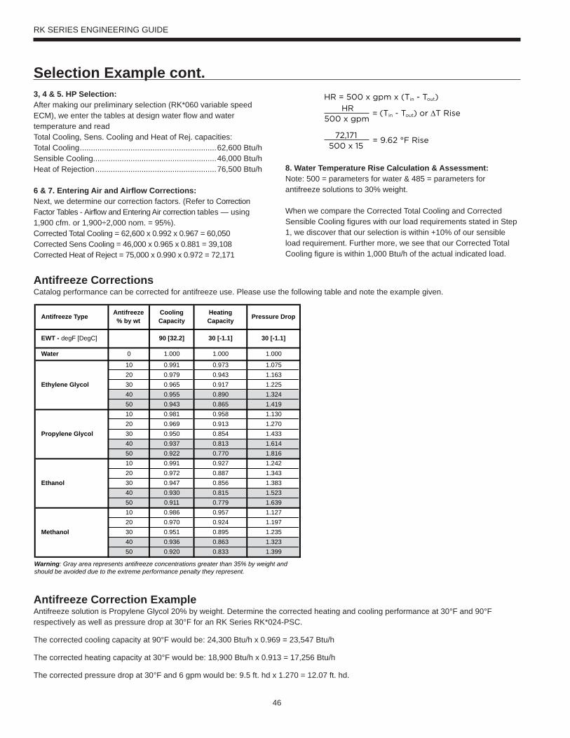
46
RK SERIES ENGINEERING GUIDE
3, 4 & 5. HP Selection:After making our preliminary selection (RK*060 variable speed ECM), we enter the tables at design water flow and water temperature and readTotal Cooling, Sens. Cooling and Heat of Rej. capacities:Total Cooling ..............................................................62,600 Btu/hSensible Cooling........................................................46,000 Btu/hHeat of Rejection .......................................................76,500 Btu/h
6 & 7. Entering Air and Airflow Corrections:Next, we determine our correction factors. (Refer to Correction Factor Tables - Airflow and Entering Air correction tables — using 1,900 cfm. or 1,900÷2,000 nom. = 95%).Corrected Total Cooling = 62,600 x 0.992 x 0.967 = 60,050Corrected Sens Cooling = 46,000 x 0.965 x 0.881 = 39,108Corrected Heat of Reject = 75,000 x 0.990 x 0.972 = 72,171
8. Water Temperature Rise Calculation & Assessment: Note: 500 = parameters for water & 485 = parameters for antifreeze solutions to 30% weight.
When we compare the Corrected Total Cooling and Corrected Sensible Cooling figures with our load requirements stated in Step 1, we discover that our selection is within +10% of our sensible load requirement. Further more, we see that our Corrected Total Cooling figure is within 1,000 Btu/h of the actual indicated load.
Selection Example cont.
Antifreeze CorrectionsCatalog performance can be corrected for antifreeze use. Please use the following table and note the example given.
Antifreeze Correction ExampleAntifreeze solution is Propylene Glycol 20% by weight. Determine the corrected heating and cooling performance at 30°F and 90°F respectively as well as pressure drop at 30°F for an RK Series RK*024-PSC.
The corrected cooling capacity at 90°F would be: 24,300 Btu/h x 0.969 = 23,547 Btu/h
The corrected heating capacity at 30°F would be: 18,900 Btu/h x 0.913 = 17,256 Btu/h
The corrected pressure drop at 30°F and 6 gpm would be: 9.5 ft. hd x 1.270 = 12.07 ft. hd.
Antifreeze Type Antifreeze% by wt
Cooling Capacity
Heating Capacity Pressure Drop
EWT - degF [DegC] 90 [32.2] 30 [-1.1] 30 [-1.1]
Water 0 1.000 1.000 1.000
10 0.991 0.973 1.07520 0.979 0.943 1.163
Ethylene Glycol 30 0.965 0.917 1.22540 0.955 0.890 1.32450 0.943 0.865 1.41910 0.981 0.958 1.13020 0.969 0.913 1.270
Propylene Glycol 30 0.950 0.854 1.43340 0.937 0.813 1.61450 0.922 0.770 1.81610 0.991 0.927 1.24220 0.972 0.887 1.343
Ethanol 30 0.947 0.856 1.38340 0.930 0.815 1.52350 0.911 0.779 1.63910 0.986 0.957 1.12720 0.970 0.924 1.197
Methanol 30 0.951 0.895 1.23540 0.936 0.863 1.32350 0.920 0.833 1.399
Warning: Gray area represents antifreeze concentrations greater than 35% by weight and should be avoided due to the extreme performance penalty they represent.
HR = 500 x gpm x (Tin - Tout)
HR = (Tin - Tout) or T Rise500 x gpm
72,171= 9.62 °F Rise
500 x 15
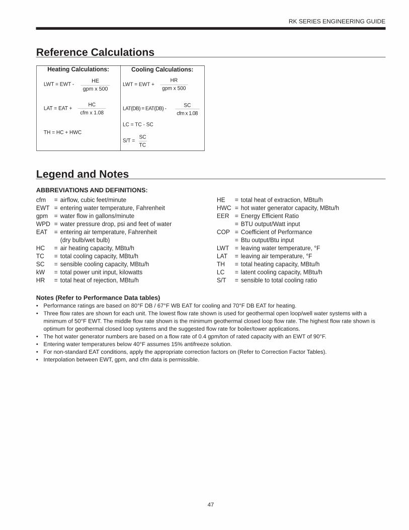
47
RK SERIES ENGINEERING GUIDE
Reference Calculations
Legend and NotesABBREVIATIONS AND DEFINITIONS:cfm = airflow, cubic feet/minuteEWT = entering water temperature, Fahrenheitgpm = water flow in gallons/minuteWPD = water pressure drop, psi and feet of waterEAT = entering air temperature, Fahrenheit (dry bulb/wet bulb)HC = air heating capacity, MBtu/hTC = total cooling capacity, MBtu/hSC = sensible cooling capacity, MBtu/hkW = total power unit input, kilowattsHR = total heat of rejection, MBtu/h
HE = total heat of extraction, MBtu/hHWC = hot water generator capacity, MBtu/hEER = Energy Efficient Ratio = BTU output/Watt inputCOP = Coefficient of Performance = Btu output/Btu inputLWT = leaving water temperature, °FLAT = leaving air temperature, °FTH = total heating capacity, MBtu/hLC = latent cooling capacity, MBtu/hS/T = sensible to total cooling ratio
Notes (Refer to Performance Data tables)• Performance ratings are based on 80°F DB / 67°F WB EAT for cooling and 70°F DB EAT for heating.• Three flow rates are shown for each unit. The lowest flow rate shown is used for geothermal open loop/well water systems with a minimum of 50°F EWT. The middle flow rate shown is the minimum geothermal closed loop flow rate. The highest flow rate shown is optimum for geothermal closed loop systems and the suggested flow rate for boiler/tower applications. • The hot water generator numbers are based on a flow rate of 0.4 gpm/ton of rated capacity with an EWT of 90°F.• Entering water temperatures below 40°F assumes 15% antifreeze solution. • For non-standard EAT conditions, apply the appropriate correction factors on (Refer to Correction Factor Tables). • Interpolation between EWT, gpm, and cfm data is permissible.
Heating Calculations: Cooling Calculations:
LWT = EWT +
LAT(DB) = EAT(DB) -
LC = TC - SC
S/T =
HRgpm x 500
SCcfm x 1.08
SCTC
HEgpm x 500
LWT = EWT -
LAT = EAT +
TH = HC + HWC
HCcfm x 1.08
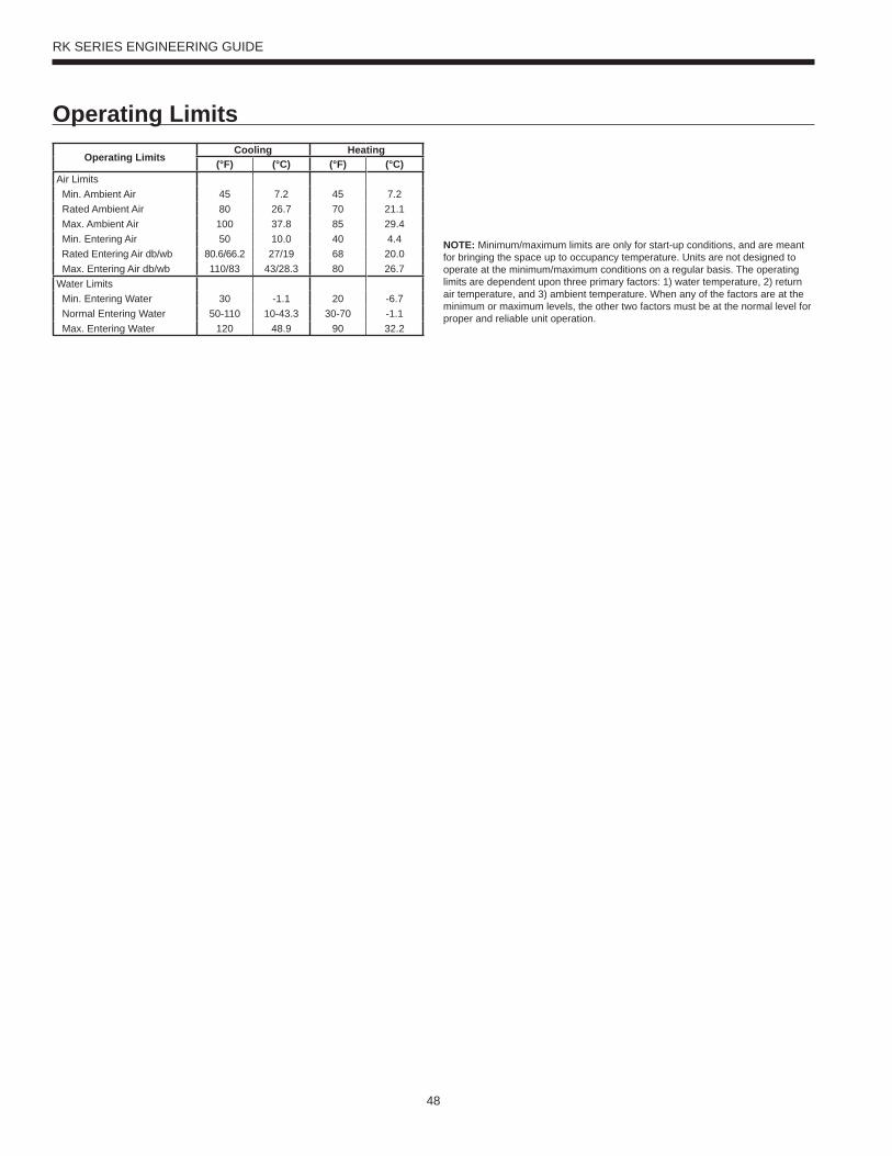
48
RK SERIES ENGINEERING GUIDE
Operating LimitsOperating Limits
Cooling Heating(°F) (°C) (°F) (°C)
Air Limits Min. Ambient Air 45 7.2 45 7.2 Rated Ambient Air 80 26.7 70 21.1 Max. Ambient Air 100 37.8 85 29.4 Min. Entering Air 50 10.0 40 4.4 Rated Entering Air db/wb 80.6/66.2 27/19 68 20.0 Max. Entering Air db/wb 110/83 43/28.3 80 26.7Water Limits Min. Entering Water 30 -1.1 20 -6.7 Normal Entering Water 50-110 10-43.3 30-70 -1.1 Max. Entering Water 120 48.9 90 32.2
NOTE: Minimum/maximum limits are only for start-up conditions, and are meant for bringing the space up to occupancy temperature. Units are not designed to operate at the minimum/maximum conditions on a regular basis. The operating limits are dependent upon three primary factors: 1) water temperature, 2) return air temperature, and 3) ambient temperature. When any of the factors are at the minimum or maximum levels, the other two factors must be at the normal level for proper and reliable unit operation.
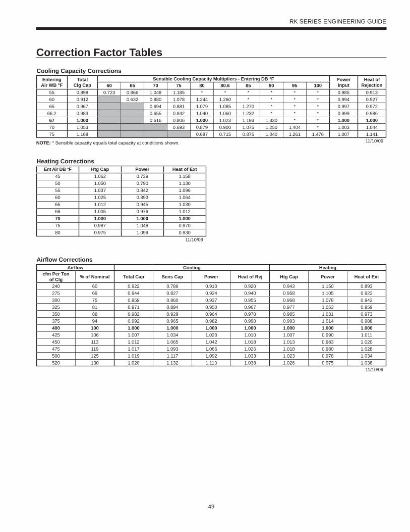
49
RK SERIES ENGINEERING GUIDE
Correction Factor TablesCooling Capacity Corrections
EnteringAir WB °F
TotalClg Cap
Sensible Cooling Capacity Multipliers - Entering DB °F PowerInput
Heat ofRejection60 65 70 75 80 80.6 85 90 95 100
55 0.898 0.723 0.866 1.048 1.185 * * * * * * 0.985 0.91360 0.912 0.632 0.880 1.078 1.244 1.260 * * * * 0.994 0.92765 0.967 0.694 0.881 1.079 1.085 1.270 * * * 0.997 0.972
66.2 0.983 0.655 0.842 1.040 1.060 1.232 * * * 0.999 0.98667 1.000 0.616 0.806 1.000 1.023 1.193 1.330 * * 1.000 1.00070 1.053 0.693 0.879 0.900 1.075 1.250 1.404 * 1.003 1.04475 1.168 0.687 0.715 0.875 1.040 1.261 1.476 1.007 1.141
11/10/09NOTE: * Sensible capacity equals total capacity at conditions shown.
Airfl ow CorrectionsAirfl ow Cooling Heating
cfm Per Ton of Clg % of Nominal Total Cap Sens Cap Power Heat of Rej Htg Cap Power Heat of Ext
240 60 0.922 0.786 0.910 0.920 0.943 1.150 0.893275 69 0.944 0.827 0.924 0.940 0.958 1.105 0.922300 75 0.959 0.860 0.937 0.955 0.968 1.078 0.942325 81 0.971 0.894 0.950 0.967 0.977 1.053 0.959350 88 0.982 0.929 0.964 0.978 0.985 1.031 0.973375 94 0.992 0.965 0.982 0.990 0.993 1.014 0.988400 100 1.000 1.000 1.000 1.000 1.000 1.000 1.000425 106 1.007 1.034 1.020 1.010 1.007 0.990 1.011450 113 1.012 1.065 1.042 1.018 1.013 0.983 1.020475 119 1.017 1.093 1.066 1.026 1.018 0.980 1.028500 125 1.019 1.117 1.092 1.033 1.023 0.978 1.034520 130 1.020 1.132 1.113 1.038 1.026 0.975 1.038
11/10/09
Heating CorrectionsEnt Air DB °F Htg Cap Power Heat of Ext
45 1.062 0.739 1.15850 1.050 0.790 1.13055 1.037 0.842 1.09660 1.025 0.893 1.06465 1.012 0.945 1.03068 1.005 0.976 1.01270 1.000 1.000 1.00075 0.987 1.048 0.97080 0.975 1.099 0.930
11/10/09
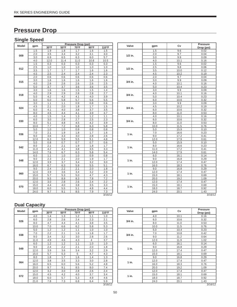
50
RK SERIES ENGINEERING GUIDE
Pressure DropSingle Speed
Model gpm Pressure Drop (psi) Valve gpm Cv Pressure Drop (psi)30°F 50°F 70°F 90°F 110°F
009
1.5 1.9 1.8 1.7 1.6 1.5
1/2 in.
1.5 9.6 0.022.0 3.5 3.4 3.2 3.1 3.0 2.0 9.7 0.043.0 6.9 6.5 6.3 6.0 5.7 3.0 9.9 0.094.0 12.0 11.4 11.0 10.8 10.5 4.0 10.1 0.16
012
1.5 0.3 0.3 0.3 0.3 0.3
1/2 in.
1.5 9.6 0.022.5 1.0 1.0 1.0 1.0 1.0 2.5 9.8 0.063.5 1.7 1.7 1.7 1.6 1.6 3.5 10.0 0.124.5 2.5 2.4 2.4 2.4 2.3 4.5 10.2 0.19
015
2.0 0.6 0.6 0.6 0.6 0.6
3/4 in.
2.0 9.7 0.043.0 1.6 1.6 1.6 1.6 1.6 3.0 9.9 0.094.0 2.6 2.6 2.6 2.6 2.5 4.0 10.1 0.165.0 3.7 3.7 3.6 3.6 3.5 5.0 10.4 0.23
018
3.0 1.6 1.6 1.5 1.5 1.4
3/4 in.
3.0 9.9 0.094.0 2.9 2.9 2.8 2.8 2.7 4.0 10.1 0.165.0 4.2 4.2 4.1 4.0 3.9 5.0 10.4 0.236.0 6.0 5.8 5.7 5.6 5.5 6.0 10.6 0.32
024
3.0 1.1 1.1 0.9 0.8 0.6
3/4 in.
3.0 9.9 0.094.5 2.1 2.0 1.8 1.7 1.5 4.5 10.2 0.196.0 4.1 4.0 3.8 3.7 3.5 6.0 10.6 0.328.0 4.5 4.4 4.1 3.9 3.7 8.0 11.0 0.53
030
4.0 1.5 1.4 1.3 1.2 1.1
3/4 in.
4.0 10.1 0.166.0 3.0 2.8 2.7 2.5 2.3 6.0 10.6 0.328.0 5.1 4.8 4.5 4.2 3.9 8.0 11.0 0.53
10.0 7.7 7.2 6.8 6.3 5.8 10.0 11.5 0.76
036
5.0 1.0 1.0 0.9 0.8 0.8
1 in.
5.0 15.9 0.107.0 2.1 1.9 1.8 1.7 1.6 7.0 16.6 0.239.0 3.6 3.3 3.0 2.8 2.6 9.0 17.2 0.41
12.0 6.3 5.9 5.5 5.1 4.8 12.0 17.9 0.61
042
5.0 0.8 0.7 0.7 0.7 0.6
1 in.
5.0 15.9 0.108.0 2.1 2.1 1.9 1.8 1.7 8.0 16.6 0.2311.0 4.2 4.1 3.8 3.5 3.3 11.0 17.2 0.4114.0 7.6 6.7 6.3 5.8 5.4 14.0 17.9 0.61
048
6.0 1.1 1.0 1.0 0.9 0.8
1 in.
6.0 16.1 0.149.0 2.3 2.1 2.0 1.9 1.7 9.0 16.8 0.29
12.0 3.9 3.7 3.4 3.2 3.0 12.0 17.4 0.4716.0 6.7 6.3 5.9 5.5 5.1 16.0 18.3 0.76
060
9.0 2.4 2.2 2.1 2.0 1.8
1 in.
9.0 16.8 0.2912.0 3.9 3.6 3.4 3.2 2.9 12.0 17.4 0.4715.0 5.7 5.3 5.0 4.7 4.3 15.0 18.1 0.6920.0 9.5 8.9 8.3 7.8 7.2 20.0 19.2 1.09
070
12.0 3.0 2.8 2.6 2.4 2.2
1 in.
12.0 17.4 0.4715.0 4.4 4.0 3.8 3.5 3.3 15.0 18.1 0.6918.0 6.0 5.5 5.1 4.8 4.4 18.0 18.7 0.9224.0 9.7 9.1 8.5 7.9 7.3 24.0 20.1 1.43
3/16/12 3/16/12
Dual CapacityModel gpm Pressure Drop (psi) Valve gpm Cv Pressure
Drop (psi)30°F 50°F 70°F 90°F 110°F
026
4.0 1.4 1.3 1.2 1.1 1.0
3/4 in.
4.0 10.1 0.166.0 2.8 2.6 2.4 2.3 2.1 6.0 10.6 0.328.0 4.7 4.4 4.1 3.8 3.5 8.0 11.0 0.53
10.0 7.0 6.6 6.2 5.8 5.3 10.0 11.5 0.76
038
5.0 1.2 1.2 1.1 1.0 1.0
3/4 in.
5.0 10.4 0.237.0 2.2 2.1 1.9 1.8 1.7 7.0 10.8 0.429.0 3.4 3.2 3.0 2.8 2.6 9.0 11.2 0.6411.0 4.9 4.6 4.3 4 3.7 12.0 11.9 1.02
049
6.0 1.2 1.2 1.1 1.0 1.0
1 in.
6.0 16.1 0.149.0 2.4 2.2 2.1 2.0 1.8 9.0 16.8 0.29
12.0 3.9 3.6 3.4 3.2 2.9 12.0 17.4 0.4715.0 5.7 5.3 5 4.7 4.3 15.0 18.1 0.69
064
8.0 1.8 1.7 1.6 1.4 1.3
1 in.
9.0 16.8 0.2912.0 3.8 3.5 3.3 3.0 2.8 12.0 17.4 0.4716.0 6.5 6.0 5.6 5.2 4.8 16.0 18.3 0.7620.0 9.7 9.1 8.5 8.0 7.4 20.0 19.2 1.09
072
12.0 3.2 3.0 2.8 2.6 2.4
1 in.
12.0 17.4 0.4715.0 4.5 4.2 4.0 3.7 3.4 15.0 18.1 0.6918.0 6.0 5.7 5.3 4.9 4.6 18.0 18.7 0.9221.0 7.8 7.3 6.8 6.4 5.9 24.0 20.1 1.43
3/16/12 3/16/12
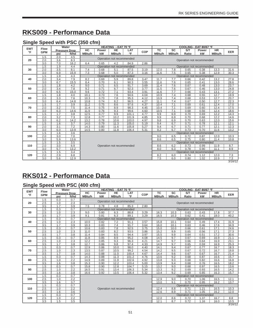
51
RK SERIES ENGINEERING GUIDE
Single Speed with PSC (350 cfm)EWT
°FFlow GPM
WaterPressure Drop
HEATING - EAT 70 °F COOLING - EAT 80/67 °FHC
MBtu/hPower
kWHE
MBtu/hLAT°F COP TC
MBtu/hSC
MBtu/hS/T
RatioPower
kWHR
MBtu/h EERpsi ft/hd
201.5 2.0 4.5 Operation not recommended Operation not recommended2.0 3.6 8.33.0 7.0 16.2 6.4 0.65 4.2 84.9 2.86
301.5 1.9 4.4 Operation not recommended Operation not recommended2.0 3.5 8.1 7.4 0.68 5.1 87.5 3.19 12.0 7.8 0.65 0.38 13.3 31.63.0 6.9 15.9 7.3 0.68 5.0 87.3 3.16 11.6 7.5 0.65 0.38 12.9 30.3
401.5 1.9 4.3 Operation not recommended Operation not recommended2.0 3.4 7.9 8.2 0.69 5.9 89.8 3.47 11.7 7.7 0.66 0.42 13.2 27.83.0 6.7 15.5 8.4 0.70 6.1 90.3 3.55 11.6 7.6 0.65 0.41 13.0 28.6
501.5 1.8 4.2 9.0 0.71 6.5 91.7 3.69 11.4 7.6 0.67 0.48 13.0 23.72.0 3.4 7.8 9.2 0.71 6.7 92.3 3.77 11.5 7.6 0.67 0.46 13.0 24.83.0 6.5 15.0 9.6 0.72 7.1 93.4 3.91 11.6 7.7 0.66 0.43 13.1 27.2
601.5 1.8 4.0 10.1 0.73 7.6 94.6 4.04 10.9 7.4 0.68 0.55 12.7 19.92.0 3.3 7.6 10.3 0.73 7.8 95.3 4.12 10.9 7.4 0.68 0.53 12.7 20.73.0 6.4 14.8 10.8 0.74 8.2 96.5 4.27 11.1 7.4 0.67 0.50 12.7 22.3
701.5 1.7 3.9 11.2 0.75 8.6 97.6 4.37 10.4 7.1 0.69 0.61 12.4 17.02.0 3.2 7.5 11.4 0.75 8.9 98.3 4.45 10.4 7.1 0.69 0.60 12.4 17.53.0 6.3 14.6 11.9 0.76 9.3 99.6 4.60 10.5 7.1 0.68 0.56 12.4 18.6
801.5 1.7 3.8 12.5 0.77 9.9 101.1 4.77 9.9 6.9 0.70 0.69 12.2 14.32.0 3.2 7.3 12.8 0.77 10.2 101.9 4.85 9.9 6.9 0.70 0.68 12.2 14.63.0 6.2 14.2 13.2 0.78 10.6 103.0 4.97 9.8 6.9 0.70 0.63 12.0 15.6
901.5 1.6 3.7 14.0 0.79 11.3 105.0 5.19 9.4 6.7 0.71 0.78 12.1 12.12.0 3.1 7.2 14.3 0.80 11.6 105.8 5.27 9.4 6.7 0.71 0.77 12.1 12.33.0 6.0 13.9 14.5 0.80 11.8 106.4 5.31 9.2 6.7 0.73 0.70 11.6 13.2
1001.5 1.6 3.6
Operation not recommended
Operation not recommended2.0 3.0 7.0 9.0 6.5 0.72 0.87 12.0 10.33.0 5.9 13.6 8.6 6.5 0.75 0.80 11.4 10.8
1101.5 1.5 3.5 Operation not recommended2.0 3.0 6.9 8.6 6.2 0.73 0.99 11.9 8.73.0 5.7 13.2 8.0 6.3 0.78 0.90 11.1 8.9
1201.5 1.5 3.4 Operation not recommended2.0 2.9 6.8 8.2 6.0 0.74 1.12 12.0 7.33.0 5.6 12.9 7.5 6.0 0.80 1.02 10.9 7.3
3/16/12
Single Speed with PSC (400 cfm)EWT
°FFlow GPM
WaterPressure Drop
HEATING - EAT 70 °F COOLING - EAT 80/67 °FHC
MBtu/hPower
kWHE
MBtu/hLAT°F COP TC
MBtu/hSC
MBtu/hS/T
RatioPower
kWHR
MBtu/h EERpsi ft/hd
201.5 0.3 0.7 Operation not recommended Operation not recommended2.5 1.0 2.33.5 1.7 3.9 7.5 0.78 4.8 85.3 2.80
301.5 0.3 0.7 Operation not recommended Operation not recommended2.5 1.0 2.3 9.0 0.80 6.3 88.8 3.29 16.3 10.3 0.63 0.43 17.8 37.73.5 1.7 3.9 9.1 0.81 6.3 89.1 3.29 16.5 10.3 0.62 0.41 18.0 40.2
401.5 0.3 0.7 Operation not recommended Operation not recommended2.5 1.0 2.3 10.0 0.82 7.2 91.1 3.57 15.8 10.1 0.64 0.49 17.4 31.93.5 1.7 3.9 10.3 0.83 7.4 91.7 3.64 16.0 10.1 0.63 0.46 17.6 34.9
501.5 0.3 0.7 10.6 0.83 7.8 92.5 3.75 15.0 10.0 0.66 0.61 17.1 24.62.5 1.0 2.3 11.0 0.83 8.2 93.5 3.86 15.2 9.9 0.65 0.56 17.1 27.33.5 1.7 3.8 11.4 0.84 8.5 94.4 3.97 15.5 9.9 0.64 0.51 17.2 30.6
601.5 0.3 0.7 11.8 0.85 8.9 95.2 4.08 14.5 9.7 0.67 0.69 16.9 21.12.5 1.0 2.3 12.2 0.85 9.3 96.3 4.21 14.7 9.7 0.66 0.64 16.9 23.13.5 1.7 3.8 12.7 0.86 9.8 97.4 4.33 14.9 9.7 0.65 0.59 16.9 25.3
701.5 0.3 0.7 12.9 0.86 10.0 98.0 4.40 14.1 9.4 0.67 0.77 16.7 18.32.5 1.0 2.3 13.5 0.87 10.5 99.2 4.54 14.2 9.5 0.67 0.72 16.7 19.83.5 1.7 3.8 14.0 0.88 11.0 100.4 4.67 14.4 9.6 0.67 0.67 16.7 21.4
801.5 0.3 0.7 14.3 0.88 11.3 101.2 4.76 13.6 9.2 0.68 0.87 16.6 15.72.5 1.0 2.2 14.9 0.89 11.9 102.6 4.92 13.8 9.3 0.68 0.82 16.6 16.83.5 1.6 3.8 15.3 0.90 12.2 103.4 5.00 13.9 9.4 0.68 0.76 16.5 18.2
901.5 0.3 0.7 15.8 0.90 12.8 104.7 5.15 13.2 9.0 0.68 0.97 16.5 13.62.5 1.0 2.2 16.5 0.91 13.4 106.3 5.34 13.3 9.2 0.69 0.93 16.5 14.23.5 1.6 3.8 16.6 0.92 13.5 106.4 5.32 13.4 9.2 0.69 0.85 16.3 15.7
1001.5 0.3 0.7
Operation not recommended
Operation not recommended2.5 1.0 2.2 12.9 9.0 0.70 1.06 16.5 12.13.5 1.6 3.7 13.0 9.1 0.70 0.95 16.2 13.7
1101.5 0.3 0.7 Operation not recommended2.5 1.0 2.2 12.4 8.8 0.71 1.21 16.5 10.33.5 1.6 3.6 12.6 8.9 0.71 1.05 16.2 12.0
1201.5 0.3 0.7 Operation not recommended2.5 1.0 2.2 12.0 8.6 0.72 1.37 16.7 8.83.5 1.5 3.5 12.1 8.7 0.72 1.16 16.0 10.5
3/16/12
RKS009 - Performance Data
RKS012 - Performance Data
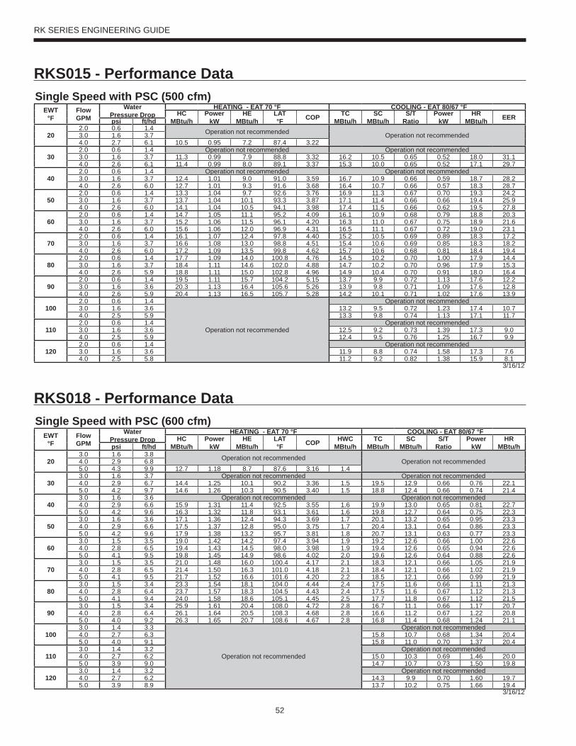
52
RK SERIES ENGINEERING GUIDE
Single Speed with PSC (500 cfm)EWT
°FFlow GPM
WaterPressure Drop
HEATING - EAT 70 °F COOLING - EAT 80/67 °FHC
MBtu/hPower
kWHE
MBtu/hLAT°F COP TC
MBtu/hSC
MBtu/hS/T
RatioPower
kWHR
MBtu/h EERpsi ft/hd
202.0 0.6 1.4 Operation not recommended Operation not recommended3.0 1.6 3.74.0 2.7 6.1 10.5 0.95 7.2 87.4 3.22
302.0 0.6 1.4 Operation not recommended Operation not recommended3.0 1.6 3.7 11.3 0.99 7.9 88.8 3.32 16.2 10.5 0.65 0.52 18.0 31.14.0 2.6 6.1 11.4 0.99 8.0 89.1 3.37 15.3 10.0 0.65 0.52 17.1 29.7
402.0 0.6 1.4 Operation not recommended Operation not recommended3.0 1.6 3.7 12.4 1.01 9.0 91.0 3.59 16.7 10.9 0.66 0.59 18.7 28.24.0 2.6 6.0 12.7 1.01 9.3 91.6 3.68 16.4 10.7 0.66 0.57 18.3 28.7
502.0 0.6 1.4 13.3 1.04 9.7 92.6 3.76 16.9 11.3 0.67 0.70 19.3 24.23.0 1.6 3.7 13.7 1.04 10.1 93.3 3.87 17.1 11.4 0.66 0.66 19.4 25.94.0 2.6 6.0 14.1 1.04 10.5 94.1 3.98 17.4 11.5 0.66 0.62 19.5 27.8
602.0 0.6 1.4 14.7 1.05 11.1 95.2 4.09 16.1 10.9 0.68 0.79 18.8 20.33.0 1.6 3.7 15.2 1.06 11.5 96.1 4.20 16.3 11.0 0.67 0.75 18.9 21.64.0 2.6 6.0 15.6 1.06 12.0 96.9 4.31 16.5 11.1 0.67 0.72 19.0 23.1
702.0 0.6 1.4 16.1 1.07 12.4 97.8 4.40 15.2 10.5 0.69 0.89 18.3 17.23.0 1.6 3.7 16.6 1.08 13.0 98.8 4.51 15.4 10.6 0.69 0.85 18.3 18.24.0 2.6 6.0 17.2 1.09 13.5 99.8 4.62 15.7 10.6 0.68 0.81 18.4 19.4
802.0 0.6 1.4 17.7 1.09 14.0 100.8 4.76 14.5 10.2 0.70 1.00 17.9 14.43.0 1.6 3.7 18.4 1.11 14.6 102.0 4.88 14.7 10.2 0.70 0.96 17.9 15.34.0 2.6 5.9 18.8 1.11 15.0 102.8 4.96 14.9 10.4 0.70 0.91 18.0 16.4
902.0 0.6 1.4 19.5 1.11 15.7 104.2 5.15 13.7 9.9 0.72 1.13 17.6 12.23.0 1.6 3.6 20.3 1.13 16.4 105.6 5.26 13.9 9.8 0.71 1.09 17.6 12.84.0 2.6 5.9 20.4 1.13 16.5 105.7 5.28 14.2 10.1 0.71 1.02 17.6 13.9
1002.0 0.6 1.4
Operation not recommended
Operation not recommended3.0 1.6 3.6 13.2 9.5 0.72 1.23 17.4 10.74.0 2.5 5.9 13.3 9.8 0.74 1.13 17.1 11.7
1102.0 0.6 1.4 Operation not recommended3.0 1.6 3.6 12.5 9.2 0.73 1.39 17.3 9.04.0 2.5 5.9 12.4 9.5 0.76 1.25 16.7 9.9
1202.0 0.6 1.4 Operation not recommended3.0 1.6 3.6 11.9 8.8 0.74 1.58 17.3 7.64.0 2.5 5.8 11.2 9.2 0.82 1.38 15.9 8.1
3/16/12
Single Speed with PSC (600 cfm)EWT
°FFlow GPM
WaterPressure Drop
HEATING - EAT 70 °F COOLING - EAT 80/67 °FHC
MBtu/hPower
kWHE
MBtu/hLAT°F COP HWC
MBtu/hTC
MBtu/hSC
MBtu/hS/T
RatioPower
kWHR
MBtu/hpsi ft/hd
203.0 1.6 3.8 Operation not recommended Operation not recommended4.0 2.9 6.85.0 4.3 9.9 12.7 1.18 8.7 87.6 3.16 1.4
303.0 1.6 3.7 Operation not recommended Operation not recommended4.0 2.9 6.7 14.4 1.25 10.1 90.2 3.36 1.5 19.5 12.9 0.66 0.76 22.15.0 4.2 9.7 14.6 1.26 10.3 90.5 3.40 1.5 18.8 12.4 0.66 0.74 21.4
403.0 1.6 3.6 Operation not recommended Operation not recommended4.0 2.9 6.6 15.9 1.31 11.4 92.5 3.55 1.6 19.9 13.0 0.65 0.81 22.75.0 4.2 9.6 16.3 1.32 11.8 93.1 3.61 1.6 19.8 12.7 0.64 0.75 22.3
503.0 1.6 3.6 17.1 1.36 12.4 94.3 3.69 1.7 20.1 13.2 0.65 0.95 23.34.0 2.9 6.6 17.5 1.37 12.8 95.0 3.75 1.7 20.4 13.1 0.64 0.86 23.35.0 4.2 9.6 17.9 1.38 13.2 95.7 3.81 1.8 20.7 13.1 0.63 0.77 23.3
603.0 1.5 3.5 19.0 1.42 14.2 97.4 3.94 1.9 19.2 12.6 0.66 1.00 22.64.0 2.8 6.5 19.4 1.43 14.5 98.0 3.98 1.9 19.4 12.6 0.65 0.94 22.65.0 4.1 9.5 19.8 1.45 14.9 98.6 4.02 2.0 19.6 12.6 0.64 0.88 22.6
703.0 1.5 3.5 21.0 1.48 16.0 100.4 4.17 2.1 18.3 12.1 0.66 1.05 21.94.0 2.8 6.5 21.4 1.50 16.3 101.0 4.18 2.1 18.4 12.1 0.66 1.02 21.95.0 4.1 9.5 21.7 1.52 16.6 101.6 4.20 2.2 18.5 12.1 0.66 0.99 21.9
803.0 1.5 3.4 23.3 1.54 18.1 104.0 4.44 2.4 17.5 11.6 0.66 1.11 21.34.0 2.8 6.4 23.7 1.57 18.3 104.5 4.43 2.4 17.5 11.6 0.67 1.12 21.35.0 4.1 9.4 24.0 1.58 18.6 105.1 4.45 2.5 17.7 11.8 0.67 1.12 21.5
903.0 1.5 3.4 25.9 1.61 20.4 108.0 4.72 2.8 16.7 11.1 0.66 1.17 20.74.0 2.8 6.4 26.1 1.64 20.5 108.3 4.68 2.8 16.6 11.2 0.67 1.22 20.85.0 4.0 9.2 26.3 1.65 20.7 108.6 4.67 2.8 16.8 11.4 0.68 1.24 21.1
1003.0 1.4 3.3
Operation not recommended
Operation not recommended4.0 2.7 6.3 15.8 10.7 0.68 1.34 20.45.0 4.0 9.1 15.8 11.0 0.70 1.37 20.4
1103.0 1.4 3.2 Operation not recommended4.0 2.7 6.2 15.0 10.3 0.69 1.46 20.05.0 3.9 9.0 14.7 10.7 0.73 1.50 19.8
1203.0 1.4 3.2 Operation not recommended4.0 2.7 6.2 14.3 9.9 0.70 1.60 19.75.0 3.9 8.9 13.7 10.2 0.75 1.66 19.4
3/16/12
RKS015 - Performance Data
RKS018 - Performance Data
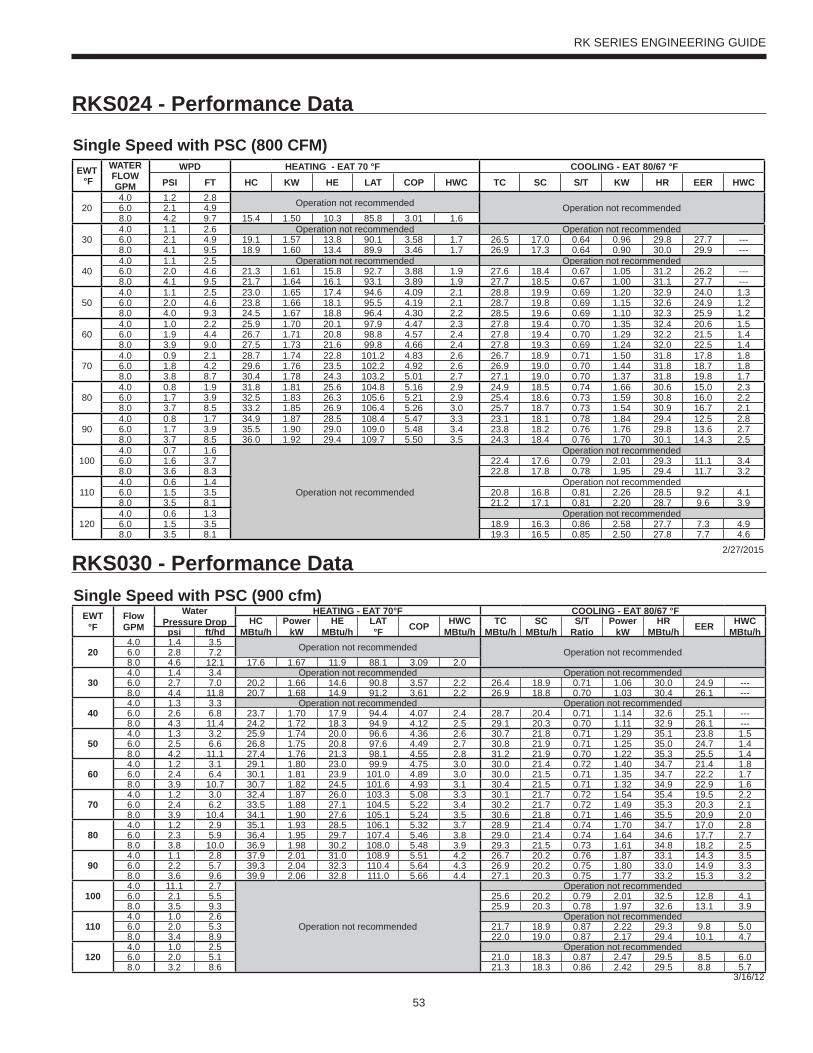
53
RK SERIES ENGINEERING GUIDE
Single Speed with PSC (900 cfm)EWT
°FFlow GPM
WaterPressure Drop
HEATING - EAT 70°F COOLING - EAT 80/67 °FHC
MBtu/hPower
kWHE
MBtu/hLAT °F COP HWC
MBtu/hTC
MBtu/hSC
MBtu/hS/T
RatioPower
kWHR
MBtu/h EER HWC MBtu/hpsi ft/hd
204.0 1.4 3.5 Operation not recommended Operation not recommended6.0 2.8 7.28.0 4.6 12.1 17.6 1.67 11.9 88.1 3.09 2.0
304.0 1.4 3.4 Operation not recommended Operation not recommended6.0 2.7 7.0 20.2 1.66 14.6 90.8 3.57 2.2 26.4 18.9 0.71 1.06 30.0 24.9 ---8.0 4.4 11.8 20.7 1.68 14.9 91.2 3.61 2.2 26.9 18.8 0.70 1.03 30.4 26.1 ---
404.0 1.3 3.3 Operation not recommended Operation not recommended6.0 2.6 6.8 23.7 1.70 17.9 94.4 4.07 2.4 28.7 20.4 0.71 1.14 32.6 25.1 ---8.0 4.3 11.4 24.2 1.72 18.3 94.9 4.12 2.5 29.1 20.3 0.70 1.11 32.9 26.1 ---
504.0 1.3 3.2 25.9 1.74 20.0 96.6 4.36 2.6 30.7 21.8 0.71 1.29 35.1 23.8 1.56.0 2.5 6.6 26.8 1.75 20.8 97.6 4.49 2.7 30.8 21.9 0.71 1.25 35.0 24.7 1.48.0 4.2 11.1 27.4 1.76 21.3 98.1 4.55 2.8 31.2 21.9 0.70 1.22 35.3 25.5 1.4
604.0 1.2 3.1 29.1 1.80 23.0 99.9 4.75 3.0 30.0 21.4 0.72 1.40 34.7 21.4 1.86.0 2.4 6.4 30.1 1.81 23.9 101.0 4.89 3.0 30.0 21.5 0.71 1.35 34.7 22.2 1.78.0 3.9 10.7 30.7 1.82 24.5 101.6 4.93 3.1 30.4 21.5 0.71 1.32 34.9 22.9 1.6
704.0 1.2 3.0 32.4 1.87 26.0 103.3 5.08 3.3 30.1 21.7 0.72 1.54 35.4 19.5 2.26.0 2.4 6.2 33.5 1.88 27.1 104.5 5.22 3.4 30.2 21.7 0.72 1.49 35.3 20.3 2.18.0 3.9 10.4 34.1 1.90 27.6 105.1 5.24 3.5 30.6 21.8 0.71 1.46 35.5 20.9 2.0
804.0 1.2 2.9 35.1 1.93 28.5 106.1 5.32 3.7 28.9 21.4 0.74 1.70 34.7 17.0 2.86.0 2.3 5.9 36.4 1.95 29.7 107.4 5.46 3.8 29.0 21.4 0.74 1.64 34.6 17.7 2.78.0 3.8 10.0 36.9 1.98 30.2 108.0 5.48 3.9 29.3 21.5 0.73 1.61 34.8 18.2 2.5
904.0 1.1 2.8 37.9 2.01 31.0 108.9 5.51 4.2 26.7 20.2 0.76 1.87 33.1 14.3 3.56.0 2.2 5.7 39.3 2.04 32.3 110.4 5.64 4.3 26.9 20.2 0.75 1.80 33.0 14.9 3.38.0 3.6 9.6 39.9 2.06 32.8 111.0 5.66 4.4 27.1 20.3 0.75 1.77 33.2 15.3 3.2
1004.0 11.1 2.7
Operation not recommended
Operation not recommended6.0 2.1 5.5 25.6 20.2 0.79 2.01 32.5 12.8 4.18.0 3.5 9.3 25.9 20.3 0.78 1.97 32.6 13.1 3.9
1104.0 1.0 2.6 Operation not recommended6.0 2.0 5.3 21.7 18.9 0.87 2.22 29.3 9.8 5.08.0 3.4 8.9 22.0 19.0 0.87 2.17 29.4 10.1 4.7
1204.0 1.0 2.5 Operation not recommended6.0 2.0 5.1 21.0 18.3 0.87 2.47 29.5 8.5 6.08.0 3.2 8.6 21.3 18.3 0.86 2.42 29.5 8.8 5.7
3/16/12
Single Speed with PSC (800 CFM)EWT °F
WATER FLOWGPM
WPD HEATING - EAT 70 °F COOLING - EAT 80/67 °FPSI FT HC KW HE LAT COP HWC TC SC S/T KW HR EER HWC
4.0 1.2 2.8 Operation not recommended Operation not recommended20 6.0 2.1 4.98.0 4.2 9.7 15.4 1.50 10.3 85.8 3.01 1.64.0 1.1 2.6 Operation not recommended Operation not recommended
30 6.0 2.1 4.9 19.1 1.57 13.8 90.1 3.58 1.7 26.5 17.0 0.64 0.96 29.8 27.7 ---8.0 4.1 9.5 18.9 1.60 13.4 89.9 3.46 1.7 26.9 17.3 0.64 0.90 30.0 29.9 ---4.0 1.1 2.5 Operation not recommended Operation not recommended
40 6.0 2.0 4.6 21.3 1.61 15.8 92.7 3.88 1.9 27.6 18.4 0.67 1.05 31.2 26.2 ---8.0 4.1 9.5 21.7 1.64 16.1 93.1 3.89 1.9 27.7 18.5 0.67 1.00 31.1 27.7 ---4.0 1.1 2.5 23.0 1.65 17.4 94.6 4.09 2.1 28.8 19.9 0.69 1.20 32.9 24.0 1.3
50 6.0 2.0 4.6 23.8 1.66 18.1 95.5 4.19 2.1 28.7 19.8 0.69 1.15 32.6 24.9 1.28.0 4.0 9.3 24.5 1.67 18.8 96.4 4.30 2.2 28.5 19.6 0.69 1.10 32.3 25.9 1.24.0 1.0 2.2 25.9 1.70 20.1 97.9 4.47 2.3 27.8 19.4 0.70 1.35 32.4 20.6 1.5
60 6.0 1.9 4.4 26.7 1.71 20.8 98.8 4.57 2.4 27.8 19.4 0.70 1.29 32.2 21.5 1.48.0 3.9 9.0 27.5 1.73 21.6 99.8 4.66 2.4 27.8 19.3 0.69 1.24 32.0 22.5 1.44.0 0.9 2.1 28.7 1.74 22.8 101.2 4.83 2.6 26.7 18.9 0.71 1.50 31.8 17.8 1.8
70 6.0 1.8 4.2 29.6 1.76 23.5 102.2 4.92 2.6 26.9 19.0 0.70 1.44 31.8 18.7 1.88.0 3.8 8.7 30.4 1.78 24.3 103.2 5.01 2.7 27.1 19.0 0.70 1.37 31.8 19.8 1.74.0 0.8 1.9 31.8 1.81 25.6 104.8 5.16 2.9 24.9 18.5 0.74 1.66 30.6 15.0 2.3
80 6.0 1.7 3.9 32.5 1.83 26.3 105.6 5.21 2.9 25.4 18.6 0.73 1.59 30.8 16.0 2.28.0 3.7 8.5 33.2 1.85 26.9 106.4 5.26 3.0 25.7 18.7 0.73 1.54 30.9 16.7 2.14.0 0.8 1.7 34.9 1.87 28.5 108.4 5.47 3.3 23.1 18.1 0.78 1.84 29.4 12.5 2.8
90 6.0 1.7 3.9 35.5 1.90 29.0 109.0 5.48 3.4 23.8 18.2 0.76 1.76 29.8 13.6 2.78.0 3.7 8.5 36.0 1.92 29.4 109.7 5.50 3.5 24.3 18.4 0.76 1.70 30.1 14.3 2.54.0 0.7 1.6
Operation not recommended
Operation not recommended100 6.0 1.6 3.7 22.4 17.6 0.79 2.01 29.3 11.1 3.4
8.0 3.6 8.3 22.8 17.8 0.78 1.95 29.4 11.7 3.24.0 0.6 1.4 Operation not recommended
110 6.0 1.5 3.5 20.8 16.8 0.81 2.26 28.5 9.2 4.18.0 3.5 8.1 21.2 17.1 0.81 2.20 28.7 9.6 3.94.0 0.6 1.3 Operation not recommended
120 6.0 1.5 3.5 18.9 16.3 0.86 2.58 27.7 7.3 4.98.0 3.5 8.1 19.3 16.5 0.85 2.50 27.8 7.7 4.6
2/27/2015
RKS024 - Performance Data
RKS030 - Performance Data
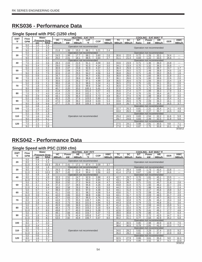
54
RK SERIES ENGINEERING GUIDE
Single Speed with PSC (1250 cfm)EWT
°FFlow GPM
WaterPressure Drop
HEATING - EAT 70°F COOLING - EAT 80/67 °FHC
MBtu/hPower
kWHE
MBtu/hLAT °F COP HWC
MBtu/hTC
MBtu/hSC
MBtu/hS/T
RatioPower
kWHR
MBtu/h EER HWC MBtu/hpsi ft/hd
205.0 1.0 2.4 Operation not recommended Operation not recommended7.0 2.1 4.99.0 3.6 8.2 21.8 1.99 15.0 86.1 3.21 2.4
305.0 1.0 2.3 Operation not recommended Operation not recommended7.0 2.1 4.7 24.5 1.99 17.7 88.1 3.60 2.6 30.6 22.0 0.72 1.26 33.1 24.4 ---9.0 3.5 8.0 25.0 2.01 18.1 88.5 3.64 2.7 31.1 21.4 0.69 1.22 33.5 25.6 ---
405.0 1.0 2.3 Operation not recommended Operation not recommended7.0 2.0 4.6 28.4 2.04 21.5 91.1 4.09 3.0 33.6 23.9 0.71 1.36 36.0 24.8 ---9.0 3.4 7.8 29.0 2.06 22.0 91.5 4.14 3.0 34.1 23.9 0.70 1.32 36.5 25.8 ---
505.0 1.0 2.2 30.9 2.07 23.8 92.9 4.37 3.2 36.3 25.9 0.71 1.53 38.7 23.7 1.77.0 1.9 4.5 32.0 2.08 24.9 93.7 4.51 3.3 36.4 26.0 0.72 1.48 38.8 24.6 1.69.0 3.3 7.5 32.6 2.10 25.5 94.2 4.56 3.4 36.8 26.0 0.71 1.45 39.2 25.5 1.6
605.0 0.9 2.1 34.7 2.11 27.5 95.7 4.81 3.6 36.0 26.5 0.74 1.65 38.5 21.8 2.17.0 1.9 4.3 35.9 2.12 28.6 96.6 4.95 3.7 36.1 26.6 0.74 1.60 38.6 22.6 2.09.0 3.1 7.3 36.6 2.15 29.2 97.1 4.99 3.8 36.5 26.6 0.73 1.56 39.0 23.4 1.9
705.0 0.9 2.1 38.6 2.16 31.3 98.6 5.24 4.1 36.5 27.5 0.75 1.81 39.1 20.1 2.67.0 1.8 4.2 40.0 2.18 32.6 99.6 5.38 4.2 36.6 27.5 0.75 1.75 39.2 20.9 2.59.0 3.0 7.0 40.7 2.20 33.2 100.1 5.41 4.3 37.0 27.6 0.75 1.72 39.6 21.6 2.4
805.0 0.9 2.0 41.8 2.20 34.3 101.0 5.57 4.6 35.6 27.4 0.77 1.99 38.3 17.9 3.37.0 1.7 4.0 43.4 2.23 35.8 102.1 5.71 4.7 35.8 27.4 0.76 1.91 38.4 18.7 3.19.0 2.9 6.8 44.1 2.25 36.4 102.6 5.73 4.8 36.2 27.5 0.76 1.88 38.8 19.2 3.0
905.0 0.8 1.9 45.3 2.25 37.6 103.5 5.89 5.1 33.4 26.6 0.80 2.17 36.1 15.4 4.17.0 1.7 3.9 47.0 2.28 39.2 104.8 6.03 5.3 33.6 26.6 0.79 2.09 36.3 16.1 3.99.0 2.8 6.6 47.7 2.31 39.8 105.3 6.05 5.4 33.9 26.7 0.79 2.05 36.6 16.5 3.7
1005.0 0.8 1.8
Operation not recommended
Operation not recommended7.0 1.6 3.8 32.7 26.3 0.81 2.31 35.4 14.1 4.89.0 2.7 6.3 33.0 26.5 0.80 2.27 35.7 14.5 4.6
1105.0 0.8 1.8 Operation not recommended7.0 1.6 3.6 29.4 24.5 0.83 2.54 32.2 11.6 5.99.0 2.6 6.1 29.7 24.6 0.83 2.49 32.5 11.9 5.6
1205.0 0.7 1.7 Operation not recommended7.0 1.5 3.5 27.5 24.1 0.88 2.81 30.5 9.8 7.19.0 2.5 5.8 27.8 24.2 0.87 2.75 30.8 10.1 6.7
3/16/12
Single Speed with PSC (1350 cfm)EWT
°FFlow GPM
WaterPressure Drop
HEATING - EAT 70°F COOLING - EAT 80/67 °FHC
MBtu/hPower
kWHE
MBtu/hLAT °F COP HWC
MBtu/hTC
MBtu/hSC
MBtu/hS/T
RatioPower
kWHR
MBtu/h EER HWC MBtu/hpsi ft/hd
205.0 0.8 1.9 Operation not recommended Operation not recommended8.0 2.3 5.311.0 4.4 10.3 25.4 2.41 17.1 87.4 3.09 3.7
305.0 0.8 1.8 Operation not recommended Operation not recommended8.0 2.2 5.1 29.3 2.45 21.0 90.1 3.51 3.9 41.0 28.4 0.69 1.73 43.4 23.8 ---11.0 4.3 10.0 29.7 2.45 21.4 90.4 3.56 4.0 41.4 27.8 0.67 1.69 43.7 24.6 ---
405.0 0.8 1.8 Operation not recommended Operation not recommended8.0 2.1 4.9 33.3 2.52 24.7 92.9 3.88 4.3 42.7 29.7 0.70 1.81 45.1 23.5 ---11.0 4.2 9.7 33.9 2.52 25.3 93.3 3.94 4.4 43.1 29.7 0.69 1.77 45.5 24.4 ---
505.0 0.7 1.7 35.8 2.52 27.2 94.6 4.16 4.7 43.3 30.7 0.71 2.01 45.7 21.6 2.68.0 2.1 4.8 37.3 2.57 28.5 95.6 4.26 4.8 43.8 31.0 0.71 1.93 46.2 22.7 2.511.0 4.1 9.4 38.0 2.58 29.3 96.1 4.33 5.0 44.2 31.0 0.70 1.88 46.6 23.5 2.4
605.0 0.7 1.7 39.3 2.57 30.5 97.0 4.48 5.3 43.1 31.4 0.73 2.17 45.6 19.8 3.28.0 2.0 4.6 41.1 2.63 32.1 98.2 4.58 5.4 43.6 31.7 0.73 2.08 46.1 20.9 3.011.0 3.9 9.1 42.0 2.65 33.0 98.8 4.66 5.6 44.1 31.7 0.72 2.03 46.5 21.7 2.9
705.0 0.7 1.6 42.7 2.63 33.7 99.3 4.76 6.0 43.1 32.4 0.75 2.37 45.7 18.2 4.08.0 1.9 4.5 44.8 2.70 35.5 100.7 4.86 6.1 43.8 32.8 0.75 2.26 46.4 19.4 3.811.0 3.8 8.8 45.9 2.73 36.6 101.5 4.94 6.3 44.3 32.8 0.74 2.21 46.8 20.1 3.6
805.0 0.7 1.6 45.9 2.65 36.9 101.5 5.09 6.7 41.4 31.7 0.77 2.59 44.0 15.9 5.18.0 1.9 4.3 48.4 2.73 39.0 103.2 5.18 6.9 42.1 32.0 0.76 2.47 44.7 17.0 4.811.0 3.7 8.5 49.8 2.77 40.3 104.1 5.28 7.1 42.6 32.0 0.75 2.41 45.1 17.7 4.6
905.0 0.7 1.5 49.1 2.68 40.0 103.7 5.37 7.5 39.0 30.8 0.79 2.86 41.7 13.7 6.48.0 1.8 4.2 51.8 2.78 42.4 105.6 5.47 7.8 39.8 31.1 0.78 2.72 42.5 14.7 6.111.0 3.5 8.2 53.5 2.82 43.9 106.7 5.57 8.0 40.2 31.1 0.77 2.64 42.9 15.2 5.8
1005.0 0.6 1.5
Operation not recommended
Operation not recommended8.0 1.7 4.0 38.2 30.5 0.80 2.98 40.9 12.8 7.511.0 3.4 7.9 38.6 30.5 0.79 2.91 41.3 13.3 7.2
1105.0 0.6 1.4 Operation not recommended8.0 1.7 3.9 34.6 28.2 0.82 3.29 37.4 10.5 9.211.0 3.3 7.6 35.0 28.2 0.81 3.20 37.7 10.9 8.8
1205.0 0.6 1.3 Operation not recommended8.0 1.6 3.7 32.5 27.9 0.86 3.61 35.4 9.0 11.111.0 3.2 7.3 32.8 27.9 0.85 3.52 35.7 9.3 10.6
3/16/12
RKS036 - Performance Data
RKS042 - Performance Data
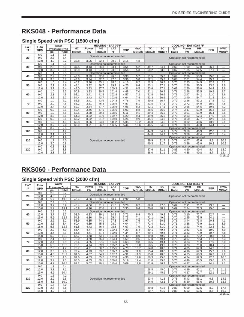
55
RK SERIES ENGINEERING GUIDE
Single Speed with PSC (1500 cfm)EWT
°FFlow GPM
WaterPressure Drop
HEATING - EAT 70°F COOLING - EAT 80/67 °FHC
MBtu/hPower
kWHE
MBtu/hLAT °F COP HWC
MBtu/hTC
MBtu/hSC
MBtu/hS/T
RatioPower
kWHR
MBtu/h EER HWC MBtu/hpsi ft/hd
206.0 1.1 2.6 Operation not recommended Operation not recommended9.0 2.3 5.4
12.0 4.0 9.2 32.8 3.05 22.4 90.2 3.15 4.8
306.0 1.1 2.5 Operation not recommended Operation not recommended9.0 2.3 5.3 37.5 3.13 26.8 93.1 3.51 5.2 49.7 34.1 0.69 1.90 52.0 26.1 ---
12.0 3.9 9.0 38.0 3.13 27.3 93.5 3.56 5.3 50.2 33.5 0.67 1.85 52.5 27.1 ---
406.0 1.1 2.5 Operation not recommended Operation not recommended9.0 2.2 5.1 43.0 3.23 32.0 96.6 3.90 5.7 51.5 35.3 0.69 2.06 53.9 25.0 ---
12.0 3.8 8.7 43.8 3.24 32.7 97.0 3.96 5.8 52.1 35.3 0.68 2.01 54.4 25.9 ---
506.0 1.0 2.4 46.2 3.26 35.1 98.5 4.16 6.2 52.5 36.7 0.70 2.35 54.9 22.3 3.19.0 2.1 4.9 48.1 3.32 36.7 99.7 4.25 6.4 53.1 37.1 0.70 2.26 55.5 23.5 2.9
12.0 3.7 8.4 49.0 3.33 37.7 100.3 4.31 6.5 53.6 37.1 0.69 2.20 56.0 24.4 2.8
606.0 1.0 2.3 50.8 3.33 39.5 101.4 4.48 7.0 51.1 36.3 0.71 2.58 53.5 19.8 3.79.0 2.1 4.8 53.1 3.41 41.5 102.8 4.57 7.2 51.8 36.6 0.71 2.47 54.2 21.0 3.6
12.0 3.5 8.2 54.4 3.43 42.7 103.6 4.64 7.4 52.3 36.6 0.70 2.40 54.7 21.8 3.4
706.0 1.0 2.2 55.5 3.41 43.9 104.3 4.78 7.9 50.8 36.7 0.72 2.86 53.2 17.8 4.79.0 2.0 4.6 58.2 3.51 46.3 105.9 4.87 8.1 51.5 37.1 0.72 2.72 54.0 18.9 4.5
12.0 3.4 7.9 59.7 3.54 47.7 106.9 4.95 8.3 52.1 37.1 0.71 2.65 54.5 19.6 4.2
806.0 0.9 2.1 59.4 3.46 47.5 106.6 5.03 8.8 48.5 35.9 0.74 3.17 51.0 15.3 5.99.0 1.9 4.5 62.5 3.58 50.3 108.6 5.11 9.1 49.4 36.2 0.73 3.01 51.9 16.4 5.6
12.0 3.3 7.6 64.3 3.62 51.9 109.7 5.20 9.4 49.9 36.2 0.73 2.93 52.4 17.0 5.4
906.0 0.9 2.1 63.2 3.52 51.2 109.0 5.26 9.9 45.1 34.2 0.76 3.50 47.7 12.9 7.49.0 1.9 4.3 66.8 3.66 54.3 111.2 5.35 10.2 46.0 34.6 0.75 3.32 48.6 13.9 7.1
12.0 3.2 7.4 68.9 3.71 56.2 112.5 5.44 10.6 46.5 34.6 0.74 3.23 49.0 14.4 6.7
1006.0 0.9 2.0
Operation not recommended
Operation not recommended9.0 1.8 4.2 44.3 34.1 0.77 3.69 46.9 12.0 8.8
12.0 3.1 7.1 44.8 34.1 0.76 3.58 47.4 12.5 8.4
1106.0 0.8 1.9 Operation not recommended9.0 1.7 4.0 39.9 31.7 0.79 4.07 42.6 9.8 10.8
12.0 3.0 6.8 40.3 31.7 0.79 3.96 43.0 10.2 10.2
1206.0 0.8 1.8 Operation not recommended9.0 1.7 3.8 37.6 31.1 0.83 4.50 40.4 8.4 13.0
12.0 2.8 6.6 38.0 31.1 0.82 4.38 40.8 8.7 12.43/16/12
Single Speed with PSC (2000 cfm)EWT
°FFlow GPM
WaterPressure Drop
HEATING - EAT 70°F COOLING - EAT 80/67 °FHC
MBtu/hPower
kWHE
MBtu/hLAT °F COP HWC
MBtu/hTC
MBtu/hSC
MBtu/hS/T
RatioPower
kWHR
MBtu/h EER HWC MBtu/hpsi ft/hd
209.0 2.5 5.7 Operation not recommended Operation not recommended12.0 4.0 9.2
15.0 5.9 13.5 40.4 4.06 26.5 88.7 2.92 5.8
309.0 2.4 5.5 Operation not recommended Operation not recommended
12.0 3.9 8.9 45.4 4.06 31.5 91.0 3.28 6.2 68.8 47.6 0.69 2.91 71.2 23.7 ---15.0 5.7 13.1 46.8 4.16 32.6 91.7 3.30 6.4 70.0 48.1 0.69 2.74 72.3 25.6 ---
409.0 2.3 5.3 Operation not recommended Operation not recommended
12.0 3.7 8.7 53.6 4.23 39.1 94.8 3.71 6.9 70.3 49.8 0.71 3.10 72.7 22.7 ---15.0 5.5 12.7 54.8 4.30 40.1 95.4 3.73 7.1 71.1 49.6 0.70 2.95 73.5 24.1 ---
509.0 2.2 5.2 58.9 4.35 44.1 97.3 3.97 7.5 71.4 50.5 0.71 3.44 73.8 20.8 4.1
12.0 3.6 8.4 60.4 4.39 45.5 98.0 4.04 7.7 71.4 51.0 0.71 3.38 73.9 21.1 3.915.0 5.3 12.3 61.5 4.43 46.4 98.5 4.07 7.9 72.2 51.0 0.71 3.23 74.6 22.3 3.7
609.0 2.2 5.0 65.4 4.47 50.1 100.3 4.29 8.4 69.1 49.4 0.71 3.63 71.5 19.0 5.0
12.0 3.5 8.1 66.8 4.51 51.4 100.9 4.34 8.7 69.4 49.6 0.71 3.53 71.9 19.7 4.815.0 5.2 11.9 68.7 4.58 53.1 101.8 4.40 8.9 69.8 49.9 0.71 3.41 72.2 20.5 4.6
709.0 2.1 4.9 72.0 4.60 56.3 103.4 4.59 9.5 67.8 49.4 0.73 3.97 70.3 17.1 6.3
12.0 3.4 7.9 73.4 4.65 57.5 104.0 4.63 9.8 68.5 49.4 0.72 3.83 71.0 17.9 6.015.0 5.0 11.6 76.1 4.74 59.9 105.2 4.71 10.0 68.5 49.9 0.73 3.73 71.0 18.4 5.7
809.0 2.0 4.7 76.7 4.71 60.7 105.5 4.78 10.7 64.8 48.0 0.74 4.35 67.3 14.9 8.0
12.0 3.3 7.6 79.4 4.73 63.2 106.7 4.92 11.0 65.4 48.0 0.73 4.16 67.9 15.7 7.615.0 4.8 11.2 81.5 4.87 64.9 107.7 4.91 11.3 65.8 48.5 0.74 4.05 68.3 16.2 7.2
909.0 2.0 4.5 81.6 4.83 65.2 107.8 4.96 12.0 60.3 45.8 0.76 4.74 62.9 12.7 10.0
12.0 3.2 7.3 85.5 4.83 69.1 109.6 5.19 12.4 61.0 45.8 0.75 4.49 63.5 13.6 9.515.0 4.7 10.8 87.2 5.02 70.1 110.4 5.09 12.8 61.6 46.3 0.75 4.37 64.1 14.1 9.1
1009.0 1.9 4.4
Operation not recommended
Operation not recommended12.0 3.1 7.1 58.5 45.0 0.77 4.99 61.1 11.7 11.815.0 4.5 10.4 59.1 45.5 0.77 4.87 61.7 12.1 11.2
1109.0 1.8 4.2 Operation not recommended
12.0 2.9 6.8 53.4 41.8 0.78 5.43 56.1 9.8 14.515.0 4.3 10.0 54.0 42.3 0.78 5.30 56.6 10.2 13.8
1209.0 1.7 4.0 Operation not recommended
12.0 2.8 6.5 49.8 41.5 0.83 6.09 52.6 8.2 17.515.0 4.2 9.6 50.7 41.9 0.83 5.92 53.5 8.6 16.7
3/16/12
RKS048 - Performance Data
RKS060 - Performance Data
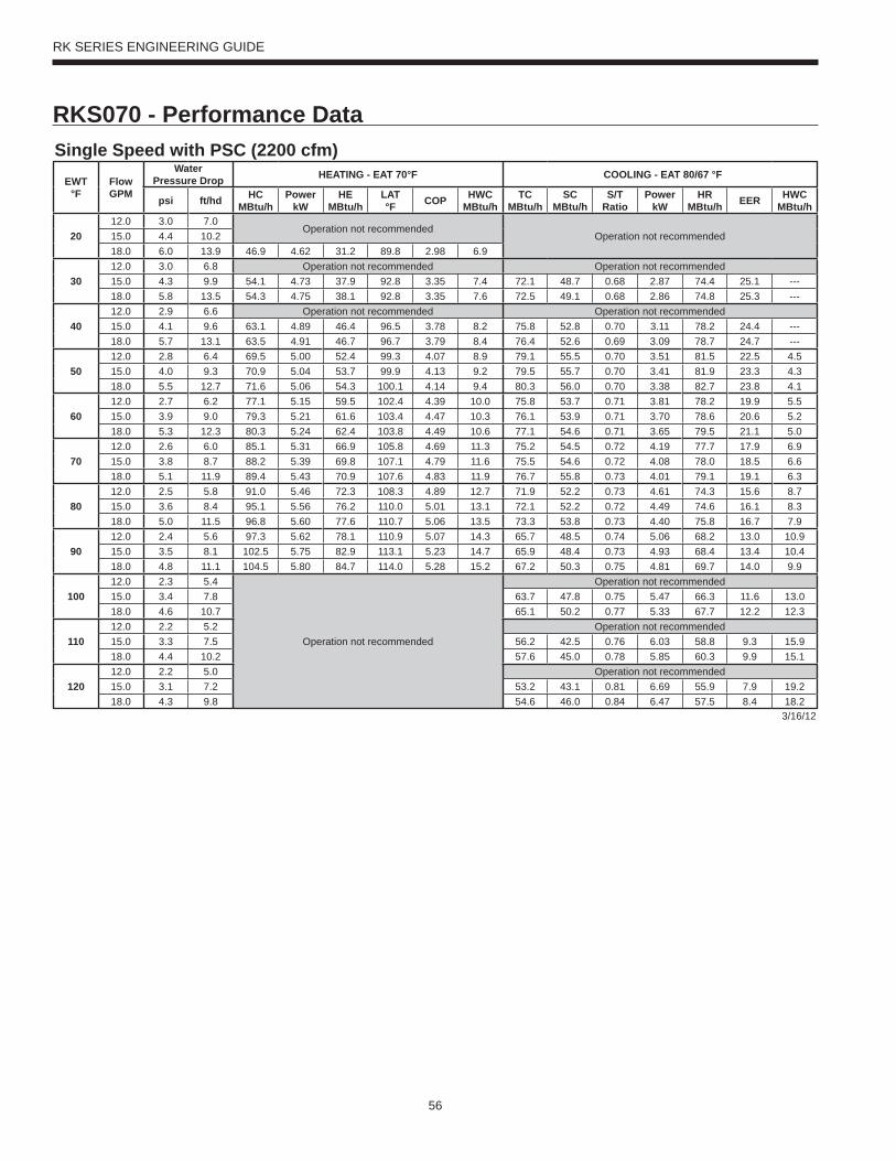
56
RK SERIES ENGINEERING GUIDE
RKS070 - Performance DataSingle Speed with PSC (2200 cfm)
EWT °F
Flow GPM
WaterPressure Drop HEATING - EAT 70°F COOLING - EAT 80/67 °F
psi ft/hd HC MBtu/h
Power kW
HE MBtu/h
LAT °F COP HWC
MBtu/hTC
MBtu/hSC
MBtu/hS/T
RatioPower
kWHR
MBtu/h EER HWC MBtu/h
2012.0 3.0 7.0
Operation not recommendedOperation not recommended15.0 4.4 10.2
18.0 6.0 13.9 46.9 4.62 31.2 89.8 2.98 6.9
3012.0 3.0 6.8 Operation not recommended Operation not recommended15.0 4.3 9.9 54.1 4.73 37.9 92.8 3.35 7.4 72.1 48.7 0.68 2.87 74.4 25.1 ---18.0 5.8 13.5 54.3 4.75 38.1 92.8 3.35 7.6 72.5 49.1 0.68 2.86 74.8 25.3 ---
4012.0 2.9 6.6 Operation not recommended Operation not recommended15.0 4.1 9.6 63.1 4.89 46.4 96.5 3.78 8.2 75.8 52.8 0.70 3.11 78.2 24.4 ---18.0 5.7 13.1 63.5 4.91 46.7 96.7 3.79 8.4 76.4 52.6 0.69 3.09 78.7 24.7 ---
5012.0 2.8 6.4 69.5 5.00 52.4 99.3 4.07 8.9 79.1 55.5 0.70 3.51 81.5 22.5 4.515.0 4.0 9.3 70.9 5.04 53.7 99.9 4.13 9.2 79.5 55.7 0.70 3.41 81.9 23.3 4.318.0 5.5 12.7 71.6 5.06 54.3 100.1 4.14 9.4 80.3 56.0 0.70 3.38 82.7 23.8 4.1
6012.0 2.7 6.2 77.1 5.15 59.5 102.4 4.39 10.0 75.8 53.7 0.71 3.81 78.2 19.9 5.515.0 3.9 9.0 79.3 5.21 61.6 103.4 4.47 10.3 76.1 53.9 0.71 3.70 78.6 20.6 5.218.0 5.3 12.3 80.3 5.24 62.4 103.8 4.49 10.6 77.1 54.6 0.71 3.65 79.5 21.1 5.0
7012.0 2.6 6.0 85.1 5.31 66.9 105.8 4.69 11.3 75.2 54.5 0.72 4.19 77.7 17.9 6.915.0 3.8 8.7 88.2 5.39 69.8 107.1 4.79 11.6 75.5 54.6 0.72 4.08 78.0 18.5 6.618.0 5.1 11.9 89.4 5.43 70.9 107.6 4.83 11.9 76.7 55.8 0.73 4.01 79.1 19.1 6.3
8012.0 2.5 5.8 91.0 5.46 72.3 108.3 4.89 12.7 71.9 52.2 0.73 4.61 74.3 15.6 8.715.0 3.6 8.4 95.1 5.56 76.2 110.0 5.01 13.1 72.1 52.2 0.72 4.49 74.6 16.1 8.318.0 5.0 11.5 96.8 5.60 77.6 110.7 5.06 13.5 73.3 53.8 0.73 4.40 75.8 16.7 7.9
9012.0 2.4 5.6 97.3 5.62 78.1 110.9 5.07 14.3 65.7 48.5 0.74 5.06 68.2 13.0 10.915.0 3.5 8.1 102.5 5.75 82.9 113.1 5.23 14.7 65.9 48.4 0.73 4.93 68.4 13.4 10.418.0 4.8 11.1 104.5 5.80 84.7 114.0 5.28 15.2 67.2 50.3 0.75 4.81 69.7 14.0 9.9
10012.0 2.3 5.4
Operation not recommended
Operation not recommended15.0 3.4 7.8 63.7 47.8 0.75 5.47 66.3 11.6 13.018.0 4.6 10.7 65.1 50.2 0.77 5.33 67.7 12.2 12.3
11012.0 2.2 5.2 Operation not recommended15.0 3.3 7.5 56.2 42.5 0.76 6.03 58.8 9.3 15.918.0 4.4 10.2 57.6 45.0 0.78 5.85 60.3 9.9 15.1
12012.0 2.2 5.0 Operation not recommended15.0 3.1 7.2 53.2 43.1 0.81 6.69 55.9 7.9 19.218.0 4.3 9.8 54.6 46.0 0.84 6.47 57.5 8.4 18.2
3/16/12
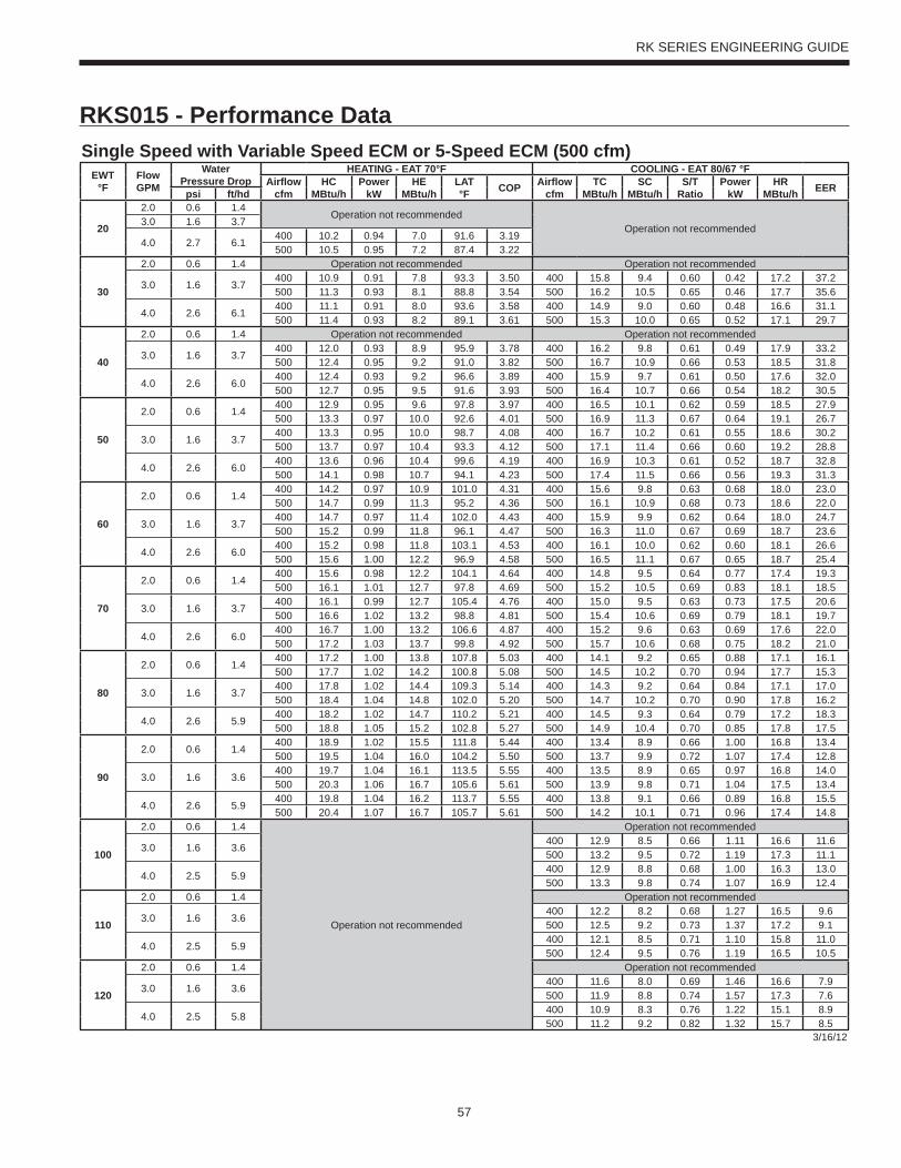
57
RK SERIES ENGINEERING GUIDE
RKS015 - Performance DataSingle Speed with Variable Speed ECM or 5-Speed ECM (500 cfm)
EWT°F
Flow GPM
WaterPressure Drop
HEATING - EAT 70°F COOLING - EAT 80/67 °FAirfl ow
cfmHC
MBtu/hPower
kWHE
MBtu/hLAT°F COP Airfl ow
cfmTC
MBtu/hSC
MBtu/hS/T
RatioPower
kWHR
MBtu/h EERpsi ft/hd
20
2.0 0.6 1.4Operation not recommended
Operation not recommended3.0 1.6 3.7
4.0 2.7 6.1400 10.2 0.94 7.0 91.6 3.19500 10.5 0.95 7.2 87.4 3.22
30
2.0 0.6 1.4 Operation not recommended Operation not recommended
3.0 1.6 3.7400 10.9 0.91 7.8 93.3 3.50 400 15.8 9.4 0.60 0.42 17.2 37.2500 11.3 0.93 8.1 88.8 3.54 500 16.2 10.5 0.65 0.46 17.7 35.6
4.0 2.6 6.1400 11.1 0.91 8.0 93.6 3.58 400 14.9 9.0 0.60 0.48 16.6 31.1500 11.4 0.93 8.2 89.1 3.61 500 15.3 10.0 0.65 0.52 17.1 29.7
40
2.0 0.6 1.4 Operation not recommended Operation not recommended
3.0 1.6 3.7400 12.0 0.93 8.9 95.9 3.78 400 16.2 9.8 0.61 0.49 17.9 33.2500 12.4 0.95 9.2 91.0 3.82 500 16.7 10.9 0.66 0.53 18.5 31.8
4.0 2.6 6.0400 12.4 0.93 9.2 96.6 3.89 400 15.9 9.7 0.61 0.50 17.6 32.0500 12.7 0.95 9.5 91.6 3.93 500 16.4 10.7 0.66 0.54 18.2 30.5
50
2.0 0.6 1.4400 12.9 0.95 9.6 97.8 3.97 400 16.5 10.1 0.62 0.59 18.5 27.9500 13.3 0.97 10.0 92.6 4.01 500 16.9 11.3 0.67 0.64 19.1 26.7
3.0 1.6 3.7400 13.3 0.95 10.0 98.7 4.08 400 16.7 10.2 0.61 0.55 18.6 30.2500 13.7 0.97 10.4 93.3 4.12 500 17.1 11.4 0.66 0.60 19.2 28.8
4.0 2.6 6.0400 13.6 0.96 10.4 99.6 4.19 400 16.9 10.3 0.61 0.52 18.7 32.8500 14.1 0.98 10.7 94.1 4.23 500 17.4 11.5 0.66 0.56 19.3 31.3
60
2.0 0.6 1.4400 14.2 0.97 10.9 101.0 4.31 400 15.6 9.8 0.63 0.68 18.0 23.0500 14.7 0.99 11.3 95.2 4.36 500 16.1 10.9 0.68 0.73 18.6 22.0
3.0 1.6 3.7400 14.7 0.97 11.4 102.0 4.43 400 15.9 9.9 0.62 0.64 18.0 24.7500 15.2 0.99 11.8 96.1 4.47 500 16.3 11.0 0.67 0.69 18.7 23.6
4.0 2.6 6.0400 15.2 0.98 11.8 103.1 4.53 400 16.1 10.0 0.62 0.60 18.1 26.6500 15.6 1.00 12.2 96.9 4.58 500 16.5 11.1 0.67 0.65 18.7 25.4
70
2.0 0.6 1.4400 15.6 0.98 12.2 104.1 4.64 400 14.8 9.5 0.64 0.77 17.4 19.3500 16.1 1.01 12.7 97.8 4.69 500 15.2 10.5 0.69 0.83 18.1 18.5
3.0 1.6 3.7400 16.1 0.99 12.7 105.4 4.76 400 15.0 9.5 0.63 0.73 17.5 20.6500 16.6 1.02 13.2 98.8 4.81 500 15.4 10.6 0.69 0.79 18.1 19.7
4.0 2.6 6.0400 16.7 1.00 13.2 106.6 4.87 400 15.2 9.6 0.63 0.69 17.6 22.0500 17.2 1.03 13.7 99.8 4.92 500 15.7 10.6 0.68 0.75 18.2 21.0
80
2.0 0.6 1.4400 17.2 1.00 13.8 107.8 5.03 400 14.1 9.2 0.65 0.88 17.1 16.1500 17.7 1.02 14.2 100.8 5.08 500 14.5 10.2 0.70 0.94 17.7 15.3
3.0 1.6 3.7400 17.8 1.02 14.4 109.3 5.14 400 14.3 9.2 0.64 0.84 17.1 17.0500 18.4 1.04 14.8 102.0 5.20 500 14.7 10.2 0.70 0.90 17.8 16.2
4.0 2.6 5.9400 18.2 1.02 14.7 110.2 5.21 400 14.5 9.3 0.64 0.79 17.2 18.3500 18.8 1.05 15.2 102.8 5.27 500 14.9 10.4 0.70 0.85 17.8 17.5
90
2.0 0.6 1.4400 18.9 1.02 15.5 111.8 5.44 400 13.4 8.9 0.66 1.00 16.8 13.4500 19.5 1.04 16.0 104.2 5.50 500 13.7 9.9 0.72 1.07 17.4 12.8
3.0 1.6 3.6400 19.7 1.04 16.1 113.5 5.55 400 13.5 8.9 0.65 0.97 16.8 14.0500 20.3 1.06 16.7 105.6 5.61 500 13.9 9.8 0.71 1.04 17.5 13.4
4.0 2.6 5.9400 19.8 1.04 16.2 113.7 5.55 400 13.8 9.1 0.66 0.89 16.8 15.5500 20.4 1.07 16.7 105.7 5.61 500 14.2 10.1 0.71 0.96 17.4 14.8
100
2.0 0.6 1.4
Operation not recommended
Operation not recommended
3.0 1.6 3.6400 12.9 8.5 0.66 1.11 16.6 11.6500 13.2 9.5 0.72 1.19 17.3 11.1
4.0 2.5 5.9400 12.9 8.8 0.68 1.00 16.3 13.0500 13.3 9.8 0.74 1.07 16.9 12.4
110
2.0 0.6 1.4 Operation not recommended
3.0 1.6 3.6400 12.2 8.2 0.68 1.27 16.5 9.6500 12.5 9.2 0.73 1.37 17.2 9.1
4.0 2.5 5.9400 12.1 8.5 0.71 1.10 15.8 11.0500 12.4 9.5 0.76 1.19 16.5 10.5
120
2.0 0.6 1.4 Operation not recommended
3.0 1.6 3.6400 11.6 8.0 0.69 1.46 16.6 7.9500 11.9 8.8 0.74 1.57 17.3 7.6
4.0 2.5 5.8400 10.9 8.3 0.76 1.22 15.1 8.9500 11.2 9.2 0.82 1.32 15.7 8.5
3/16/12
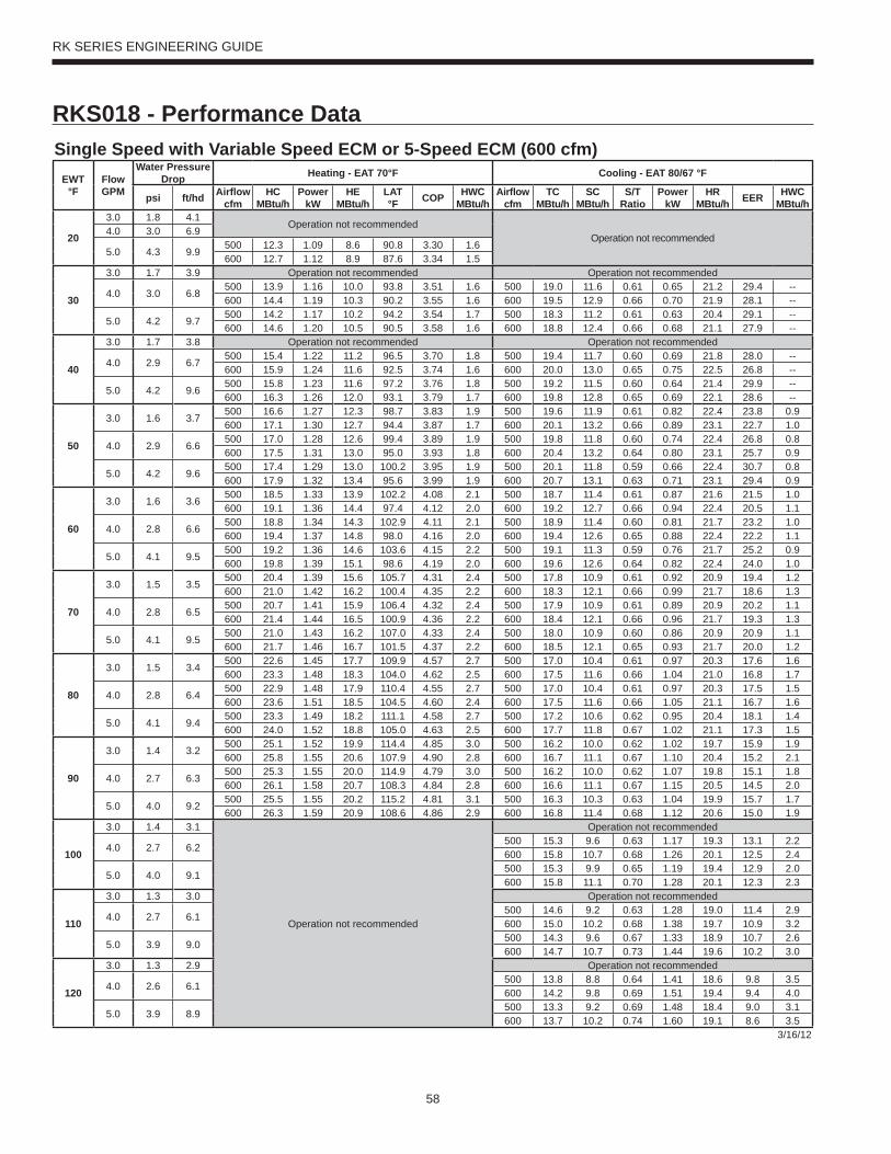
58
RK SERIES ENGINEERING GUIDE
RKS018 - Performance DataSingle Speed with Variable Speed ECM or 5-Speed ECM (600 cfm)
EWT°F
Flow GPM
Water Pressure Drop Heating - EAT 70°F Cooling - EAT 80/67 °F
psi ft/hd Airfl ow cfm
HC MBtu/h
Power kW
HE MBtu/h
LAT °F COP HWC
MBtu/hAirfl ow
cfmTC
MBtu/hSC
MBtu/hS/T
RatioPower
kWHR
MBtu/h EER HWC MBtu/h
20
3.0 1.8 4.1Operation not recommended
Operation not recommended4.0 3.0 6.9
5.0 4.3 9.9500 12.3 1.09 8.6 90.8 3.30 1.6600 12.7 1.12 8.9 87.6 3.34 1.5
30
3.0 1.7 3.9 Operation not recommended Operation not recommended
4.0 3.0 6.8500 13.9 1.16 10.0 93.8 3.51 1.6 500 19.0 11.6 0.61 0.65 21.2 29.4 --600 14.4 1.19 10.3 90.2 3.55 1.6 600 19.5 12.9 0.66 0.70 21.9 28.1 --
5.0 4.2 9.7500 14.2 1.17 10.2 94.2 3.54 1.7 500 18.3 11.2 0.61 0.63 20.4 29.1 --600 14.6 1.20 10.5 90.5 3.58 1.6 600 18.8 12.4 0.66 0.68 21.1 27.9 --
40
3.0 1.7 3.8 Operation not recommended Operation not recommended
4.0 2.9 6.7500 15.4 1.22 11.2 96.5 3.70 1.8 500 19.4 11.7 0.60 0.69 21.8 28.0 --600 15.9 1.24 11.6 92.5 3.74 1.6 600 20.0 13.0 0.65 0.75 22.5 26.8 --
5.0 4.2 9.6500 15.8 1.23 11.6 97.2 3.76 1.8 500 19.2 11.5 0.60 0.64 21.4 29.9 --600 16.3 1.26 12.0 93.1 3.79 1.7 600 19.8 12.8 0.65 0.69 22.1 28.6 --
50
3.0 1.6 3.7500 16.6 1.27 12.3 98.7 3.83 1.9 500 19.6 11.9 0.61 0.82 22.4 23.8 0.9600 17.1 1.30 12.7 94.4 3.87 1.7 600 20.1 13.2 0.66 0.89 23.1 22.7 1.0
4.0 2.9 6.6500 17.0 1.28 12.6 99.4 3.89 1.9 500 19.8 11.8 0.60 0.74 22.4 26.8 0.8600 17.5 1.31 13.0 95.0 3.93 1.8 600 20.4 13.2 0.64 0.80 23.1 25.7 0.9
5.0 4.2 9.6500 17.4 1.29 13.0 100.2 3.95 1.9 500 20.1 11.8 0.59 0.66 22.4 30.7 0.8600 17.9 1.32 13.4 95.6 3.99 1.9 600 20.7 13.1 0.63 0.71 23.1 29.4 0.9
60
3.0 1.6 3.6500 18.5 1.33 13.9 102.2 4.08 2.1 500 18.7 11.4 0.61 0.87 21.6 21.5 1.0600 19.1 1.36 14.4 97.4 4.12 2.0 600 19.2 12.7 0.66 0.94 22.4 20.5 1.1
4.0 2.8 6.6500 18.8 1.34 14.3 102.9 4.11 2.1 500 18.9 11.4 0.60 0.81 21.7 23.2 1.0600 19.4 1.37 14.8 98.0 4.16 2.0 600 19.4 12.6 0.65 0.88 22.4 22.2 1.1
5.0 4.1 9.5500 19.2 1.36 14.6 103.6 4.15 2.2 500 19.1 11.3 0.59 0.76 21.7 25.2 0.9600 19.8 1.39 15.1 98.6 4.19 2.0 600 19.6 12.6 0.64 0.82 22.4 24.0 1.0
70
3.0 1.5 3.5500 20.4 1.39 15.6 105.7 4.31 2.4 500 17.8 10.9 0.61 0.92 20.9 19.4 1.2600 21.0 1.42 16.2 100.4 4.35 2.2 600 18.3 12.1 0.66 0.99 21.7 18.6 1.3
4.0 2.8 6.5500 20.7 1.41 15.9 106.4 4.32 2.4 500 17.9 10.9 0.61 0.89 20.9 20.2 1.1600 21.4 1.44 16.5 100.9 4.36 2.2 600 18.4 12.1 0.66 0.96 21.7 19.3 1.3
5.0 4.1 9.5500 21.0 1.43 16.2 107.0 4.33 2.4 500 18.0 10.9 0.60 0.86 20.9 20.9 1.1600 21.7 1.46 16.7 101.5 4.37 2.2 600 18.5 12.1 0.65 0.93 21.7 20.0 1.2
80
3.0 1.5 3.4500 22.6 1.45 17.7 109.9 4.57 2.7 500 17.0 10.4 0.61 0.97 20.3 17.6 1.6600 23.3 1.48 18.3 104.0 4.62 2.5 600 17.5 11.6 0.66 1.04 21.0 16.8 1.7
4.0 2.8 6.4500 22.9 1.48 17.9 110.4 4.55 2.7 500 17.0 10.4 0.61 0.97 20.3 17.5 1.5600 23.6 1.51 18.5 104.5 4.60 2.4 600 17.5 11.6 0.66 1.05 21.1 16.7 1.6
5.0 4.1 9.4500 23.3 1.49 18.2 111.1 4.58 2.7 500 17.2 10.6 0.62 0.95 20.4 18.1 1.4600 24.0 1.52 18.8 105.0 4.63 2.5 600 17.7 11.8 0.67 1.02 21.1 17.3 1.5
90
3.0 1.4 3.2500 25.1 1.52 19.9 114.4 4.85 3.0 500 16.2 10.0 0.62 1.02 19.7 15.9 1.9600 25.8 1.55 20.6 107.9 4.90 2.8 600 16.7 11.1 0.67 1.10 20.4 15.2 2.1
4.0 2.7 6.3500 25.3 1.55 20.0 114.9 4.79 3.0 500 16.2 10.0 0.62 1.07 19.8 15.1 1.8600 26.1 1.58 20.7 108.3 4.84 2.8 600 16.6 11.1 0.67 1.15 20.5 14.5 2.0
5.0 4.0 9.2500 25.5 1.55 20.2 115.2 4.81 3.1 500 16.3 10.3 0.63 1.04 19.9 15.7 1.7600 26.3 1.59 20.9 108.6 4.86 2.9 600 16.8 11.4 0.68 1.12 20.6 15.0 1.9
100
3.0 1.4 3.1
Operation not recommended
Operation not recommended
4.0 2.7 6.2500 15.3 9.6 0.63 1.17 19.3 13.1 2.2600 15.8 10.7 0.68 1.26 20.1 12.5 2.4
5.0 4.0 9.1500 15.3 9.9 0.65 1.19 19.4 12.9 2.0600 15.8 11.1 0.70 1.28 20.1 12.3 2.3
110
3.0 1.3 3.0 Operation not recommended
4.0 2.7 6.1500 14.6 9.2 0.63 1.28 19.0 11.4 2.9600 15.0 10.2 0.68 1.38 19.7 10.9 3.2
5.0 3.9 9.0500 14.3 9.6 0.67 1.33 18.9 10.7 2.6600 14.7 10.7 0.73 1.44 19.6 10.2 3.0
120
3.0 1.3 2.9 Operation not recommended
4.0 2.6 6.1500 13.8 8.8 0.64 1.41 18.6 9.8 3.5600 14.2 9.8 0.69 1.51 19.4 9.4 4.0
5.0 3.9 8.9500 13.3 9.2 0.69 1.48 18.4 9.0 3.1600 13.7 10.2 0.74 1.60 19.1 8.6 3.5
3/16/12
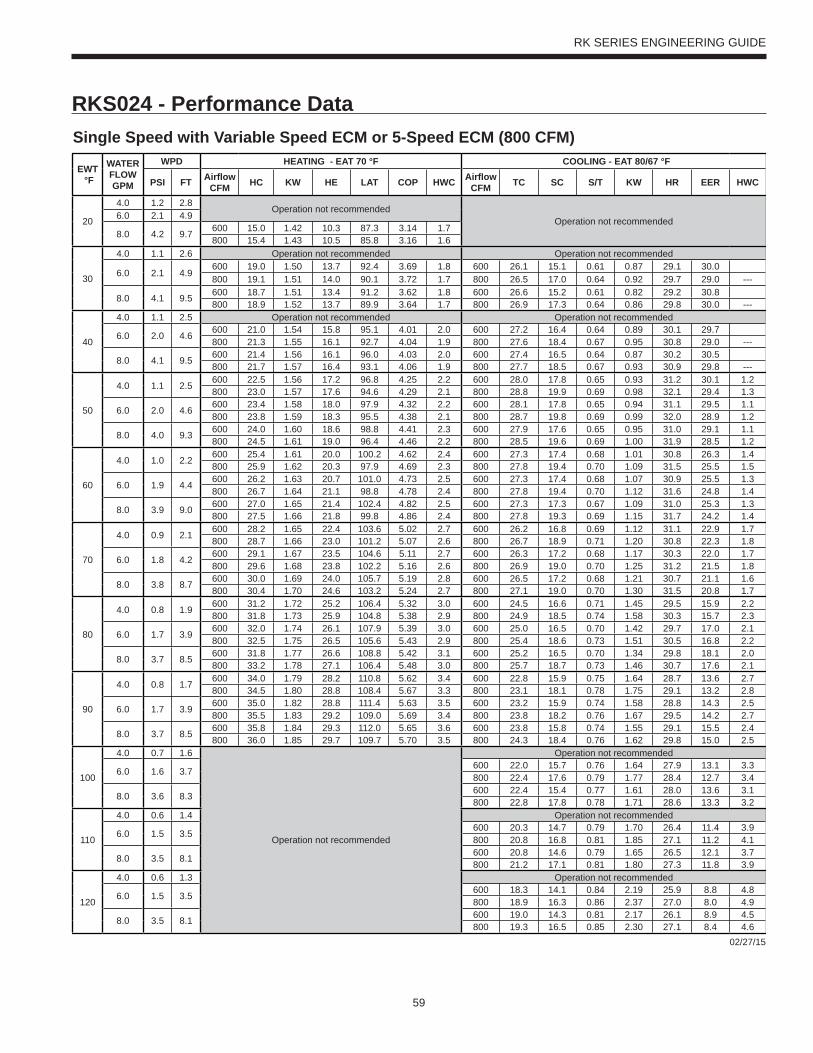
59
RK SERIES ENGINEERING GUIDE
RKS024 - Performance DataSingle Speed with Variable Speed ECM or 5-Speed ECM (800 CFM)
EWT °F
WATER FLOWGPM
WPD HEATING - EAT 70 °F COOLING - EAT 80/67 °F
PSI FT Airfl ow CFM HC KW HE LAT COP HWC Airfl ow
CFM TC SC S/T KW HR EER HWC
20
4.0 1.2 2.8Operation not recommended
Operation not recommended6.0 2.1 4.9
8.0 4.2 9.7 600 15.0 1.42 10.3 87.3 3.14 1.7800 15.4 1.43 10.5 85.8 3.16 1.6
30
4.0 1.1 2.6 Operation not recommended Operation not recommended
6.0 2.1 4.9600 19.0 1.50 13.7 92.4 3.69 1.8 600 26.1 15.1 0.61 0.87 29.1 30.0800 19.1 1.51 14.0 90.1 3.72 1.7 800 26.5 17.0 0.64 0.92 29.7 29.0 ---
8.0 4.1 9.5 600 18.7 1.51 13.4 91.2 3.62 1.8 600 26.6 15.2 0.61 0.82 29.2 30.8800 18.9 1.52 13.7 89.9 3.64 1.7 800 26.9 17.3 0.64 0.86 29.8 30.0 ---
40
4.0 1.1 2.5 Operation not recommended Operation not recommended
6.0 2.0 4.6600 21.0 1.54 15.8 95.1 4.01 2.0 600 27.2 16.4 0.64 0.89 30.1 29.7800 21.3 1.55 16.1 92.7 4.04 1.9 800 27.6 18.4 0.67 0.95 30.8 29.0 ---
8.0 4.1 9.5 600 21.4 1.56 16.1 96.0 4.03 2.0 600 27.4 16.5 0.64 0.87 30.2 30.5800 21.7 1.57 16.4 93.1 4.06 1.9 800 27.7 18.5 0.67 0.93 30.9 29.8 ---
50
4.0 1.1 2.5600 22.5 1.56 17.2 96.8 4.25 2.2 600 28.0 17.8 0.65 0.93 31.2 30.1 1.2800 23.0 1.57 17.6 94.6 4.29 2.1 800 28.8 19.9 0.69 0.98 32.1 29.4 1.3
6.0 2.0 4.6600 23.4 1.58 18.0 97.9 4.32 2.2 600 28.1 17.8 0.65 0.94 31.1 29.5 1.1800 23.8 1.59 18.3 95.5 4.38 2.1 800 28.7 19.8 0.69 0.99 32.0 28.9 1.2
8.0 4.0 9.3 600 24.0 1.60 18.6 98.8 4.41 2.3 600 27.9 17.6 0.65 0.95 31.0 29.1 1.1800 24.5 1.61 19.0 96.4 4.46 2.2 800 28.5 19.6 0.69 1.00 31.9 28.5 1.2
60
4.0 1.0 2.2600 25.4 1.61 20.0 100.2 4.62 2.4 600 27.3 17.4 0.68 1.01 30.8 26.3 1.4800 25.9 1.62 20.3 97.9 4.69 2.3 800 27.8 19.4 0.70 1.09 31.5 25.5 1.5
6.0 1.9 4.4600 26.2 1.63 20.7 101.0 4.73 2.5 600 27.3 17.4 0.68 1.07 30.9 25.5 1.3800 26.7 1.64 21.1 98.8 4.78 2.4 800 27.8 19.4 0.70 1.12 31.6 24.8 1.4
8.0 3.9 9.0 600 27.0 1.65 21.4 102.4 4.82 2.5 600 27.3 17.3 0.67 1.09 31.0 25.3 1.3800 27.5 1.66 21.8 99.8 4.86 2.4 800 27.8 19.3 0.69 1.15 31.7 24.2 1.4
70
4.0 0.9 2.1600 28.2 1.65 22.4 103.6 5.02 2.7 600 26.2 16.8 0.69 1.12 31.1 22.9 1.7800 28.7 1.66 23.0 101.2 5.07 2.6 800 26.7 18.9 0.71 1.20 30.8 22.3 1.8
6.0 1.8 4.2600 29.1 1.67 23.5 104.6 5.11 2.7 600 26.3 17.2 0.68 1.17 30.3 22.0 1.7800 29.6 1.68 23.8 102.2 5.16 2.6 800 26.9 19.0 0.70 1.25 31.2 21.5 1.8
8.0 3.8 8.7 600 30.0 1.69 24.0 105.7 5.19 2.8 600 26.5 17.2 0.68 1.21 30.7 21.1 1.6800 30.4 1.70 24.6 103.2 5.24 2.7 800 27.1 19.0 0.70 1.30 31.5 20.8 1.7
80
4.0 0.8 1.9600 31.2 1.72 25.2 106.4 5.32 3.0 600 24.5 16.6 0.71 1.45 29.5 15.9 2.2800 31.8 1.73 25.9 104.8 5.38 2.9 800 24.9 18.5 0.74 1.58 30.3 15.7 2.3
6.0 1.7 3.9600 32.0 1.74 26.1 107.9 5.39 3.0 600 25.0 16.5 0.70 1.42 29.7 17.0 2.1800 32.5 1.75 26.5 105.6 5.43 2.9 800 25.4 18.6 0.73 1.51 30.5 16.8 2.2
8.0 3.7 8.5 600 31.8 1.77 26.6 108.8 5.42 3.1 600 25.2 16.5 0.70 1.34 29.8 18.1 2.0800 33.2 1.78 27.1 106.4 5.48 3.0 800 25.7 18.7 0.73 1.46 30.7 17.6 2.1
90
4.0 0.8 1.7600 34.0 1.79 28.2 110.8 5.62 3.4 600 22.8 15.9 0.75 1.64 28.7 13.6 2.7800 34.5 1.80 28.8 108.4 5.67 3.3 800 23.1 18.1 0.78 1.75 29.1 13.2 2.8
6.0 1.7 3.9600 35.0 1.82 28.8 111.4 5.63 3.5 600 23.2 15.9 0.74 1.58 28.8 14.3 2.5800 35.5 1.83 29.2 109.0 5.69 3.4 800 23.8 18.2 0.76 1.67 29.5 14.2 2.7
8.0 3.7 8.5 600 35.8 1.84 29.3 112.0 5.65 3.6 600 23.8 15.8 0.74 1.55 29.1 15.5 2.4800 36.0 1.85 29.7 109.7 5.70 3.5 800 24.3 18.4 0.76 1.62 29.8 15.0 2.5
100
4.0 0.7 1.6
Operation not recommended
Operation not recommended
6.0 1.6 3.7600 22.0 15.7 0.76 1.64 27.9 13.1 3.3800 22.4 17.6 0.79 1.77 28.4 12.7 3.4
8.0 3.6 8.3 600 22.4 15.4 0.77 1.61 28.0 13.6 3.1800 22.8 17.8 0.78 1.71 28.6 13.3 3.2
110
4.0 0.6 1.4 Operation not recommended
6.0 1.5 3.5600 20.3 14.7 0.79 1.70 26.4 11.4 3.9800 20.8 16.8 0.81 1.85 27.1 11.2 4.1
8.0 3.5 8.1 600 20.8 14.6 0.79 1.65 26.5 12.1 3.7800 21.2 17.1 0.81 1.80 27.3 11.8 3.9
120
4.0 0.6 1.3 Operation not recommended
6.0 1.5 3.5600 18.3 14.1 0.84 2.19 25.9 8.8 4.8800 18.9 16.3 0.86 2.37 27.0 8.0 4.9
8.0 3.5 8.1 600 19.0 14.3 0.81 2.17 26.1 8.9 4.5800 19.3 16.5 0.85 2.30 27.1 8.4 4.6
02/27/15
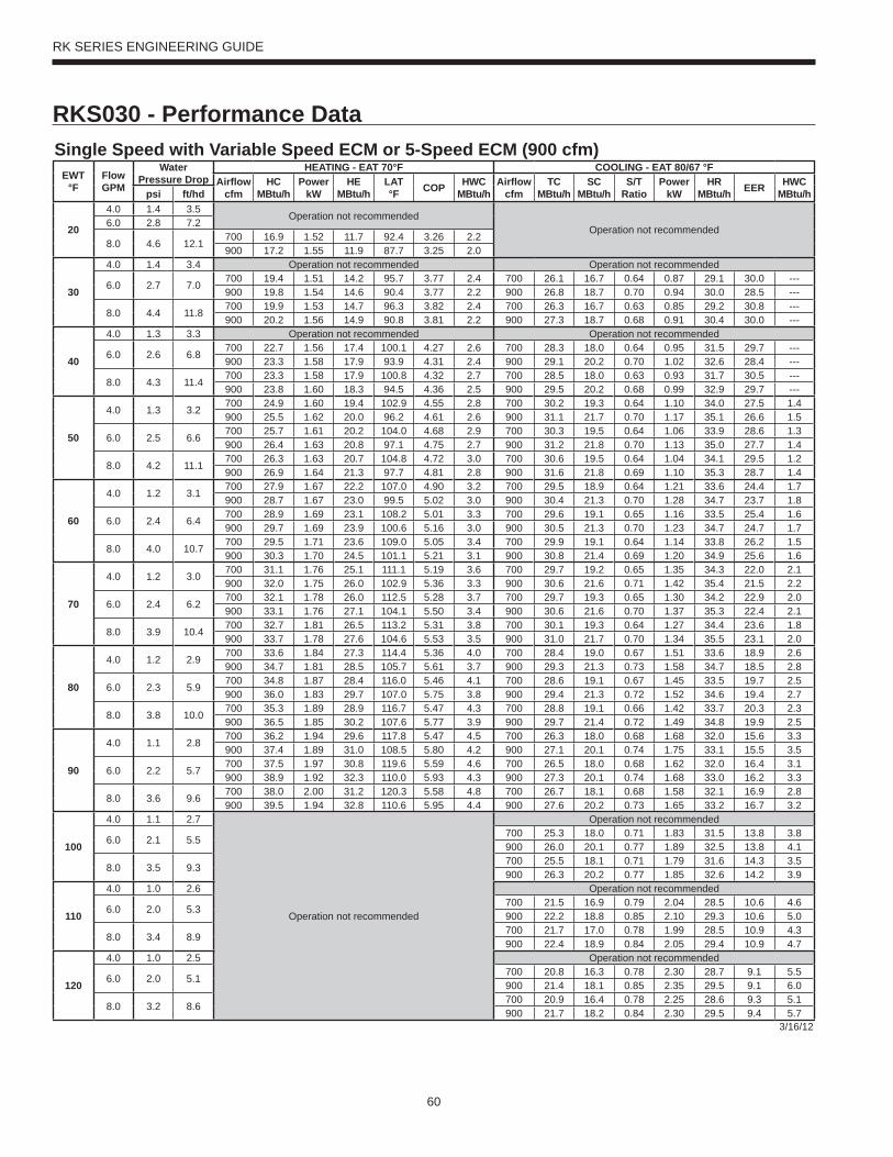
60
RK SERIES ENGINEERING GUIDE
RKS030 - Performance DataSingle Speed with Variable Speed ECM or 5-Speed ECM (900 cfm)
EWT°F
Flow GPM
WaterPressure Drop
HEATING - EAT 70°F COOLING - EAT 80/67 °FAirfl ow
cfmHC
MBtu/hPower
kWHE
MBtu/hLAT °F COP HWC
MBtu/hAirfl ow
cfmTC
MBtu/hSC
MBtu/hS/T
RatioPower
kWHR
MBtu/h EER HWC MBtu/hpsi ft/hd
20
4.0 1.4 3.5Operation not recommended
Operation not recommended6.0 2.8 7.2
8.0 4.6 12.1700 16.9 1.52 11.7 92.4 3.26 2.2900 17.2 1.55 11.9 87.7 3.25 2.0
30
4.0 1.4 3.4 Operation not recommended Operation not recommended
6.0 2.7 7.0700 19.4 1.51 14.2 95.7 3.77 2.4 700 26.1 16.7 0.64 0.87 29.1 30.0 ---900 19.8 1.54 14.6 90.4 3.77 2.2 900 26.8 18.7 0.70 0.94 30.0 28.5 ---
8.0 4.4 11.8700 19.9 1.53 14.7 96.3 3.82 2.4 700 26.3 16.7 0.63 0.85 29.2 30.8 ---900 20.2 1.56 14.9 90.8 3.81 2.2 900 27.3 18.7 0.68 0.91 30.4 30.0 ---
40
4.0 1.3 3.3 Operation not recommended Operation not recommended
6.0 2.6 6.8700 22.7 1.56 17.4 100.1 4.27 2.6 700 28.3 18.0 0.64 0.95 31.5 29.7 ---900 23.3 1.58 17.9 93.9 4.31 2.4 900 29.1 20.2 0.70 1.02 32.6 28.4 ---
8.0 4.3 11.4700 23.3 1.58 17.9 100.8 4.32 2.7 700 28.5 18.0 0.63 0.93 31.7 30.5 ---900 23.8 1.60 18.3 94.5 4.36 2.5 900 29.5 20.2 0.68 0.99 32.9 29.7 ---
50
4.0 1.3 3.2700 24.9 1.60 19.4 102.9 4.55 2.8 700 30.2 19.3 0.64 1.10 34.0 27.5 1.4900 25.5 1.62 20.0 96.2 4.61 2.6 900 31.1 21.7 0.70 1.17 35.1 26.6 1.5
6.0 2.5 6.6700 25.7 1.61 20.2 104.0 4.68 2.9 700 30.3 19.5 0.64 1.06 33.9 28.6 1.3900 26.4 1.63 20.8 97.1 4.75 2.7 900 31.2 21.8 0.70 1.13 35.0 27.7 1.4
8.0 4.2 11.1700 26.3 1.63 20.7 104.8 4.72 3.0 700 30.6 19.5 0.64 1.04 34.1 29.5 1.2900 26.9 1.64 21.3 97.7 4.81 2.8 900 31.6 21.8 0.69 1.10 35.3 28.7 1.4
60
4.0 1.2 3.1700 27.9 1.67 22.2 107.0 4.90 3.2 700 29.5 18.9 0.64 1.21 33.6 24.4 1.7900 28.7 1.67 23.0 99.5 5.02 3.0 900 30.4 21.3 0.70 1.28 34.7 23.7 1.8
6.0 2.4 6.4700 28.9 1.69 23.1 108.2 5.01 3.3 700 29.6 19.1 0.65 1.16 33.5 25.4 1.6900 29.7 1.69 23.9 100.6 5.16 3.0 900 30.5 21.3 0.70 1.23 34.7 24.7 1.7
8.0 4.0 10.7700 29.5 1.71 23.6 109.0 5.05 3.4 700 29.9 19.1 0.64 1.14 33.8 26.2 1.5900 30.3 1.70 24.5 101.1 5.21 3.1 900 30.8 21.4 0.69 1.20 34.9 25.6 1.6
70
4.0 1.2 3.0700 31.1 1.76 25.1 111.1 5.19 3.6 700 29.7 19.2 0.65 1.35 34.3 22.0 2.1900 32.0 1.75 26.0 102.9 5.36 3.3 900 30.6 21.6 0.71 1.42 35.4 21.5 2.2
6.0 2.4 6.2700 32.1 1.78 26.0 112.5 5.28 3.7 700 29.7 19.3 0.65 1.30 34.2 22.9 2.0900 33.1 1.76 27.1 104.1 5.50 3.4 900 30.6 21.6 0.70 1.37 35.3 22.4 2.1
8.0 3.9 10.4700 32.7 1.81 26.5 113.2 5.31 3.8 700 30.1 19.3 0.64 1.27 34.4 23.6 1.8900 33.7 1.78 27.6 104.6 5.53 3.5 900 31.0 21.7 0.70 1.34 35.5 23.1 2.0
80
4.0 1.2 2.9700 33.6 1.84 27.3 114.4 5.36 4.0 700 28.4 19.0 0.67 1.51 33.6 18.9 2.6900 34.7 1.81 28.5 105.7 5.61 3.7 900 29.3 21.3 0.73 1.58 34.7 18.5 2.8
6.0 2.3 5.9700 34.8 1.87 28.4 116.0 5.46 4.1 700 28.6 19.1 0.67 1.45 33.5 19.7 2.5900 36.0 1.83 29.7 107.0 5.75 3.8 900 29.4 21.3 0.72 1.52 34.6 19.4 2.7
8.0 3.8 10.0700 35.3 1.89 28.9 116.7 5.47 4.3 700 28.8 19.1 0.66 1.42 33.7 20.3 2.3900 36.5 1.85 30.2 107.6 5.77 3.9 900 29.7 21.4 0.72 1.49 34.8 19.9 2.5
90
4.0 1.1 2.8700 36.2 1.94 29.6 117.8 5.47 4.5 700 26.3 18.0 0.68 1.68 32.0 15.6 3.3900 37.4 1.89 31.0 108.5 5.80 4.2 900 27.1 20.1 0.74 1.75 33.1 15.5 3.5
6.0 2.2 5.7700 37.5 1.97 30.8 119.6 5.59 4.6 700 26.5 18.0 0.68 1.62 32.0 16.4 3.1900 38.9 1.92 32.3 110.0 5.93 4.3 900 27.3 20.1 0.74 1.68 33.0 16.2 3.3
8.0 3.6 9.6700 38.0 2.00 31.2 120.3 5.58 4.8 700 26.7 18.1 0.68 1.58 32.1 16.9 2.8900 39.5 1.94 32.8 110.6 5.95 4.4 900 27.6 20.2 0.73 1.65 33.2 16.7 3.2
100
4.0 1.1 2.7
Operation not recommended
Operation not recommended
6.0 2.1 5.5700 25.3 18.0 0.71 1.83 31.5 13.8 3.8900 26.0 20.1 0.77 1.89 32.5 13.8 4.1
8.0 3.5 9.3700 25.5 18.1 0.71 1.79 31.6 14.3 3.5900 26.3 20.2 0.77 1.85 32.6 14.2 3.9
110
4.0 1.0 2.6 Operation not recommended
6.0 2.0 5.3700 21.5 16.9 0.79 2.04 28.5 10.6 4.6900 22.2 18.8 0.85 2.10 29.3 10.6 5.0
8.0 3.4 8.9700 21.7 17.0 0.78 1.99 28.5 10.9 4.3900 22.4 18.9 0.84 2.05 29.4 10.9 4.7
120
4.0 1.0 2.5 Operation not recommended
6.0 2.0 5.1700 20.8 16.3 0.78 2.30 28.7 9.1 5.5900 21.4 18.1 0.85 2.35 29.5 9.1 6.0
8.0 3.2 8.6700 20.9 16.4 0.78 2.25 28.6 9.3 5.1900 21.7 18.2 0.84 2.30 29.5 9.4 5.7
3/16/12
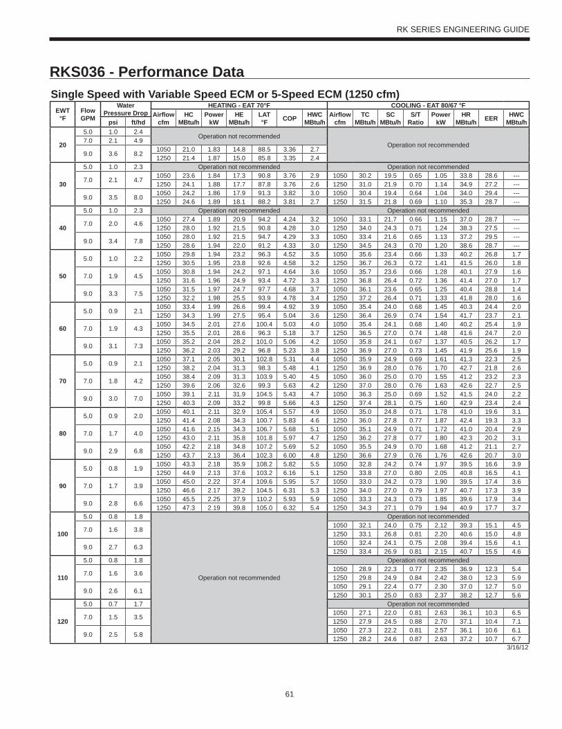
61
RK SERIES ENGINEERING GUIDE
RKS036 - Performance DataSingle Speed with Variable Speed ECM or 5-Speed ECM (1250 cfm)
EWT°F
Flow GPM
WaterPressure Drop
HEATING - EAT 70°F COOLING - EAT 80/67 °FAirfl ow
cfmHC
MBtu/hPower
kWHE
MBtu/hLAT °F COP HWC
MBtu/hAirfl ow
cfmTC
MBtu/hSC
MBtu/hS/T
RatioPower
kWHR
MBtu/h EER HWC MBtu/hpsi ft/hd
20
5.0 1.0 2.4Operation not recommended
Operation not recommended7.0 2.1 4.9
9.0 3.6 8.21050 21.0 1.83 14.8 88.5 3.36 2.71250 21.4 1.87 15.0 85.8 3.35 2.4
30
5.0 1.0 2.3 Operation not recommended Operation not recommended
7.0 2.1 4.71050 23.6 1.84 17.3 90.8 3.76 2.9 1050 30.2 19.5 0.65 1.05 33.8 28.6 ---1250 24.1 1.88 17.7 87.8 3.76 2.6 1250 31.0 21.9 0.70 1.14 34.9 27.2 ---
9.0 3.5 8.01050 24.2 1.86 17.9 91.3 3.82 3.0 1050 30.4 19.4 0.64 1.04 34.0 29.4 ---1250 24.6 1.89 18.1 88.2 3.81 2.7 1250 31.5 21.8 0.69 1.10 35.3 28.7 ---
40
5.0 1.0 2.3 Operation not recommended Operation not recommended
7.0 2.0 4.61050 27.4 1.89 20.9 94.2 4.24 3.2 1050 33.1 21.7 0.66 1.15 37.0 28.7 ---1250 28.0 1.92 21.5 90.8 4.28 3.0 1250 34.0 24.3 0.71 1.24 38.3 27.5 ---
9.0 3.4 7.81050 28.0 1.92 21.5 94.7 4.29 3.3 1050 33.4 21.6 0.65 1.13 37.2 29.5 ---1250 28.6 1.94 22.0 91.2 4.33 3.0 1250 34.5 24.3 0.70 1.20 38.6 28.7 ---
50
5.0 1.0 2.21050 29.8 1.94 23.2 96.3 4.52 3.5 1050 35.6 23.4 0.66 1.33 40.2 26.8 1.71250 30.5 1.95 23.8 92.6 4.58 3.2 1250 36.7 26.3 0.72 1.41 41.5 26.0 1.8
7.0 1.9 4.51050 30.8 1.94 24.2 97.1 4.64 3.6 1050 35.7 23.6 0.66 1.28 40.1 27.9 1.61250 31.6 1.96 24.9 93.4 4.72 3.3 1250 36.8 26.4 0.72 1.36 41.4 27.0 1.7
9.0 3.3 7.51050 31.5 1.97 24.7 97.7 4.68 3.7 1050 36.1 23.6 0.65 1.25 40.4 28.8 1.41250 32.2 1.98 25.5 93.9 4.78 3.4 1250 37.2 26.4 0.71 1.33 41.8 28.0 1.6
60
5.0 0.9 2.11050 33.4 1.99 26.6 99.4 4.92 3.9 1050 35.4 24.0 0.68 1.45 40.3 24.4 2.01250 34.3 1.99 27.5 95.4 5.04 3.6 1250 36.4 26.9 0.74 1.54 41.7 23.7 2.1
7.0 1.9 4.31050 34.5 2.01 27.6 100.4 5.03 4.0 1050 35.4 24.1 0.68 1.40 40.2 25.4 1.91250 35.5 2.01 28.6 96.3 5.18 3.7 1250 36.5 27.0 0.74 1.48 41.6 24.7 2.0
9.0 3.1 7.31050 35.2 2.04 28.2 101.0 5.06 4.2 1050 35.8 24.1 0.67 1.37 40.5 26.2 1.71250 36.2 2.03 29.2 96.8 5.23 3.8 1250 36.9 27.0 0.73 1.45 41.9 25.6 1.9
70
5.0 0.9 2.11050 37.1 2.05 30.1 102.8 5.31 4.4 1050 35.9 24.9 0.69 1.61 41.3 22.3 2.51250 38.2 2.04 31.3 98.3 5.48 4.1 1250 36.9 28.0 0.76 1.70 42.7 21.8 2.6
7.0 1.8 4.21050 38.4 2.09 31.3 103.9 5.40 4.5 1050 36.0 25.0 0.70 1.55 41.2 23.2 2.31250 39.6 2.06 32.6 99.3 5.63 4.2 1250 37.0 28.0 0.76 1.63 42.6 22.7 2.5
9.0 3.0 7.01050 39.1 2.11 31.9 104.5 5.43 4.7 1050 36.3 25.0 0.69 1.52 41.5 24.0 2.21250 40.3 2.09 33.2 99.8 5.66 4.3 1250 37.4 28.1 0.75 1.60 42.9 23.4 2.4
80
5.0 0.9 2.01050 40.1 2.11 32.9 105.4 5.57 4.9 1050 35.0 24.8 0.71 1.78 41.0 19.6 3.11250 41.4 2.08 34.3 100.7 5.83 4.6 1250 36.0 27.8 0.77 1.87 42.4 19.3 3.3
7.0 1.7 4.01050 41.6 2.15 34.3 106.7 5.68 5.1 1050 35.1 24.9 0.71 1.72 41.0 20.4 2.91250 43.0 2.11 35.8 101.8 5.97 4.7 1250 36.2 27.8 0.77 1.80 42.3 20.2 3.1
9.0 2.9 6.81050 42.2 2.18 34.8 107.2 5.69 5.2 1050 35.5 24.9 0.70 1.68 41.2 21.1 2.71250 43.7 2.13 36.4 102.3 6.00 4.8 1250 36.6 27.9 0.76 1.76 42.6 20.7 3.0
90
5.0 0.8 1.91050 43.3 2.18 35.9 108.2 5.82 5.5 1050 32.8 24.2 0.74 1.97 39.5 16.6 3.91250 44.9 2.13 37.6 103.2 6.16 5.1 1250 33.8 27.0 0.80 2.05 40.8 16.5 4.1
7.0 1.7 3.91050 45.0 2.22 37.4 109.6 5.95 5.7 1050 33.0 24.2 0.73 1.90 39.5 17.4 3.61250 46.6 2.17 39.2 104.5 6.31 5.3 1250 34.0 27.0 0.79 1.97 40.7 17.3 3.9
9.0 2.8 6.61050 45.5 2.25 37.9 110.2 5.93 5.9 1050 33.3 24.3 0.73 1.85 39.6 17.9 3.41250 47.3 2.19 39.8 105.0 6.32 5.4 1250 34.3 27.1 0.79 1.94 40.9 17.7 3.7
100
5.0 0.8 1.8
Operation not recommended
Operation not recommended
7.0 1.6 3.81050 32.1 24.0 0.75 2.12 39.3 15.1 4.51250 33.1 26.8 0.81 2.20 40.6 15.0 4.8
9.0 2.7 6.31050 32.4 24.1 0.75 2.08 39.4 15.6 4.11250 33.4 26.9 0.81 2.15 40.7 15.5 4.6
110
5.0 0.8 1.8 Operation not recommended
7.0 1.6 3.61050 28.9 22.3 0.77 2.35 36.9 12.3 5.41250 29.8 24.9 0.84 2.42 38.0 12.3 5.9
9.0 2.6 6.11050 29.1 22.4 0.77 2.30 37.0 12.7 5.01250 30.1 25.0 0.83 2.37 38.2 12.7 5.6
120
5.0 0.7 1.7 Operation not recommended
7.0 1.5 3.51050 27.1 22.0 0.81 2.63 36.1 10.3 6.51250 27.9 24.5 0.88 2.70 37.1 10.4 7.1
9.0 2.5 5.81050 27.3 22.2 0.81 2.57 36.1 10.6 6.11250 28.2 24.6 0.87 2.63 37.2 10.7 6.7
3/16/12
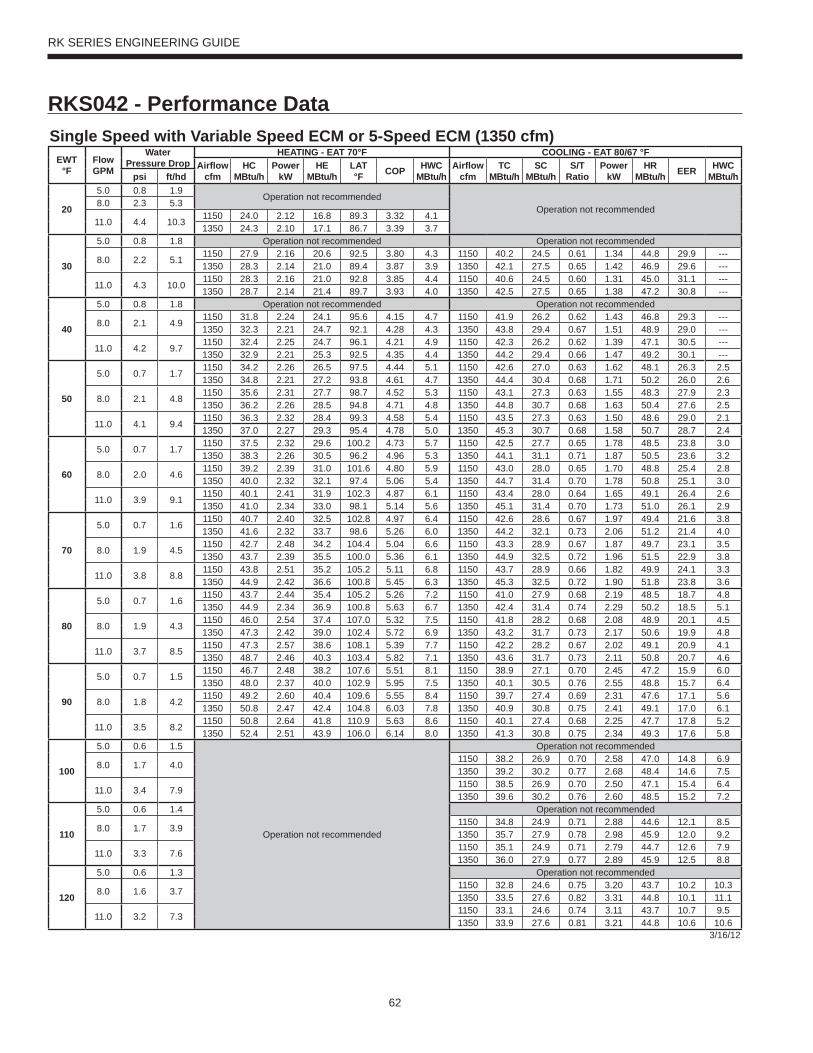
62
RK SERIES ENGINEERING GUIDE
RKS042 - Performance DataSingle Speed with Variable Speed ECM or 5-Speed ECM (1350 cfm)
EWT°F
Flow GPM
WaterPressure Drop
HEATING - EAT 70°F COOLING - EAT 80/67 °FAirfl ow
cfmHC
MBtu/hPower
kWHE
MBtu/hLAT °F COP HWC
MBtu/hAirfl ow
cfmTC
MBtu/hSC
MBtu/hS/T
RatioPower
kWHR
MBtu/h EER HWC MBtu/hpsi ft/hd
20
5.0 0.8 1.9Operation not recommended
Operation not recommended8.0 2.3 5.3
11.0 4.4 10.31150 24.0 2.12 16.8 89.3 3.32 4.11350 24.3 2.10 17.1 86.7 3.39 3.7
30
5.0 0.8 1.8 Operation not recommended Operation not recommended
8.0 2.2 5.11150 27.9 2.16 20.6 92.5 3.80 4.3 1150 40.2 24.5 0.61 1.34 44.8 29.9 ---1350 28.3 2.14 21.0 89.4 3.87 3.9 1350 42.1 27.5 0.65 1.42 46.9 29.6 ---
11.0 4.3 10.01150 28.3 2.16 21.0 92.8 3.85 4.4 1150 40.6 24.5 0.60 1.31 45.0 31.1 ---1350 28.7 2.14 21.4 89.7 3.93 4.0 1350 42.5 27.5 0.65 1.38 47.2 30.8 ---
40
5.0 0.8 1.8 Operation not recommended Operation not recommended
8.0 2.1 4.91150 31.8 2.24 24.1 95.6 4.15 4.7 1150 41.9 26.2 0.62 1.43 46.8 29.3 ---1350 32.3 2.21 24.7 92.1 4.28 4.3 1350 43.8 29.4 0.67 1.51 48.9 29.0 ---
11.0 4.2 9.71150 32.4 2.25 24.7 96.1 4.21 4.9 1150 42.3 26.2 0.62 1.39 47.1 30.5 ---1350 32.9 2.21 25.3 92.5 4.35 4.4 1350 44.2 29.4 0.66 1.47 49.2 30.1 ---
50
5.0 0.7 1.71150 34.2 2.26 26.5 97.5 4.44 5.1 1150 42.6 27.0 0.63 1.62 48.1 26.3 2.51350 34.8 2.21 27.2 93.8 4.61 4.7 1350 44.4 30.4 0.68 1.71 50.2 26.0 2.6
8.0 2.1 4.81150 35.6 2.31 27.7 98.7 4.52 5.3 1150 43.1 27.3 0.63 1.55 48.3 27.9 2.31350 36.2 2.26 28.5 94.8 4.71 4.8 1350 44.8 30.7 0.68 1.63 50.4 27.6 2.5
11.0 4.1 9.41150 36.3 2.32 28.4 99.3 4.58 5.4 1150 43.5 27.3 0.63 1.50 48.6 29.0 2.11350 37.0 2.27 29.3 95.4 4.78 5.0 1350 45.3 30.7 0.68 1.58 50.7 28.7 2.4
60
5.0 0.7 1.71150 37.5 2.32 29.6 100.2 4.73 5.7 1150 42.5 27.7 0.65 1.78 48.5 23.8 3.01350 38.3 2.26 30.5 96.2 4.96 5.3 1350 44.1 31.1 0.71 1.87 50.5 23.6 3.2
8.0 2.0 4.61150 39.2 2.39 31.0 101.6 4.80 5.9 1150 43.0 28.0 0.65 1.70 48.8 25.4 2.81350 40.0 2.32 32.1 97.4 5.06 5.4 1350 44.7 31.4 0.70 1.78 50.8 25.1 3.0
11.0 3.9 9.11150 40.1 2.41 31.9 102.3 4.87 6.1 1150 43.4 28.0 0.64 1.65 49.1 26.4 2.61350 41.0 2.34 33.0 98.1 5.14 5.6 1350 45.1 31.4 0.70 1.73 51.0 26.1 2.9
70
5.0 0.7 1.61150 40.7 2.40 32.5 102.8 4.97 6.4 1150 42.6 28.6 0.67 1.97 49.4 21.6 3.81350 41.6 2.32 33.7 98.6 5.26 6.0 1350 44.2 32.1 0.73 2.06 51.2 21.4 4.0
8.0 1.9 4.51150 42.7 2.48 34.2 104.4 5.04 6.6 1150 43.3 28.9 0.67 1.87 49.7 23.1 3.51350 43.7 2.39 35.5 100.0 5.36 6.1 1350 44.9 32.5 0.72 1.96 51.5 22.9 3.8
11.0 3.8 8.81150 43.8 2.51 35.2 105.2 5.11 6.8 1150 43.7 28.9 0.66 1.82 49.9 24.1 3.31350 44.9 2.42 36.6 100.8 5.45 6.3 1350 45.3 32.5 0.72 1.90 51.8 23.8 3.6
80
5.0 0.7 1.61150 43.7 2.44 35.4 105.2 5.26 7.2 1150 41.0 27.9 0.68 2.19 48.5 18.7 4.81350 44.9 2.34 36.9 100.8 5.63 6.7 1350 42.4 31.4 0.74 2.29 50.2 18.5 5.1
8.0 1.9 4.31150 46.0 2.54 37.4 107.0 5.32 7.5 1150 41.8 28.2 0.68 2.08 48.9 20.1 4.51350 47.3 2.42 39.0 102.4 5.72 6.9 1350 43.2 31.7 0.73 2.17 50.6 19.9 4.8
11.0 3.7 8.51150 47.3 2.57 38.6 108.1 5.39 7.7 1150 42.2 28.2 0.67 2.02 49.1 20.9 4.11350 48.7 2.46 40.3 103.4 5.82 7.1 1350 43.6 31.7 0.73 2.11 50.8 20.7 4.6
90
5.0 0.7 1.51150 46.7 2.48 38.2 107.6 5.51 8.1 1150 38.9 27.1 0.70 2.45 47.2 15.9 6.01350 48.0 2.37 40.0 102.9 5.95 7.5 1350 40.1 30.5 0.76 2.55 48.8 15.7 6.4
8.0 1.8 4.21150 49.2 2.60 40.4 109.6 5.55 8.4 1150 39.7 27.4 0.69 2.31 47.6 17.1 5.61350 50.8 2.47 42.4 104.8 6.03 7.8 1350 40.9 30.8 0.75 2.41 49.1 17.0 6.1
11.0 3.5 8.21150 50.8 2.64 41.8 110.9 5.63 8.6 1150 40.1 27.4 0.68 2.25 47.7 17.8 5.21350 52.4 2.51 43.9 106.0 6.14 8.0 1350 41.3 30.8 0.75 2.34 49.3 17.6 5.8
100
5.0 0.6 1.5
Operation not recommended
Operation not recommended
8.0 1.7 4.01150 38.2 26.9 0.70 2.58 47.0 14.8 6.91350 39.2 30.2 0.77 2.68 48.4 14.6 7.5
11.0 3.4 7.91150 38.5 26.9 0.70 2.50 47.1 15.4 6.41350 39.6 30.2 0.76 2.60 48.5 15.2 7.2
110
5.0 0.6 1.4 Operation not recommended
8.0 1.7 3.91150 34.8 24.9 0.71 2.88 44.6 12.1 8.51350 35.7 27.9 0.78 2.98 45.9 12.0 9.2
11.0 3.3 7.61150 35.1 24.9 0.71 2.79 44.7 12.6 7.91350 36.0 27.9 0.77 2.89 45.9 12.5 8.8
120
5.0 0.6 1.3 Operation not recommended
8.0 1.6 3.71150 32.8 24.6 0.75 3.20 43.7 10.2 10.31350 33.5 27.6 0.82 3.31 44.8 10.1 11.1
11.0 3.2 7.31150 33.1 24.6 0.74 3.11 43.7 10.7 9.51350 33.9 27.6 0.81 3.21 44.8 10.6 10.6
3/16/12

63
RK SERIES ENGINEERING GUIDE
RKS048 - Performance DataSingle Speed with Variable Speed ECM or 5-Speed ECM (1500 cfm)
EWT°F
Flow GPM
WaterPressure Drop HEATING - EAT 70°F COOLING - EAT 80/67 °F
psi ft/hd Airfl ow cfm
HC MBtu/h
Power kW
HE MBtu/h
LAT °F COP HWC
MBtu/hAirfl ow
cfmTC
MBtu/hSC
MBtu/hS/T
RatioPower
kWHR
MBtu/h EER HWC MBtu/h
20
6.0 1.1 2.6Operation not recommended
Operation not recommended9.0 2.3 5.4
12.0 4.0 9.21300 31.6 2.84 21.9 92.5 3.26 5.31500 32.0 2.82 22.4 89.7 3.33 4.8
30
6.0 1.1 2.5 Operation not recommended Operation not recommended
9.0 2.3 5.31300 36.3 2.92 26.3 95.8 3.64 5.6 1300 48.2 29.6 0.61 1.58 53.6 30.5 ---1500 36.7 2.90 26.8 92.6 3.71 5.2 1500 50.5 33.3 0.66 1.67 56.2 30.2 ---
12.0 3.9 9.01300 36.8 2.93 26.8 96.2 3.68 5.8 1300 48.7 29.6 0.61 1.53 53.9 31.8 ---1500 37.2 2.90 27.3 93.0 3.76 5.3 1500 51.0 33.3 0.65 1.62 56.5 31.4 ---
40
6.0 1.1 2.5 Operation not recommended Operation not recommended
9.0 2.2 5.11300 41.7 3.05 31.3 99.7 4.00 6.2 1300 50.1 31.2 0.62 1.74 56.0 28.9 ---1500 42.2 3.00 32.0 96.1 4.13 5.7 1500 52.3 35.1 0.67 1.83 58.6 28.6 ---
12.0 3.8 8.71300 42.4 3.06 31.9 100.2 4.06 6.4 1300 50.6 31.2 0.62 1.68 56.4 30.0 ---1500 43.0 3.01 32.7 96.5 4.19 5.8 1500 52.9 35.1 0.66 1.78 58.9 29.7 ---
50
6.0 1.0 2.41300 44.7 3.09 34.1 101.8 4.24 6.7 1300 51.2 32.5 0.63 2.02 58.1 25.3 2.91500 45.4 3.02 35.1 98.0 4.40 6.2 1500 53.3 36.5 0.68 2.13 60.6 25.1 3.1
9.0 2.1 4.91300 46.5 3.16 35.7 103.1 4.32 6.9 1300 51.7 32.8 0.63 1.93 58.3 26.8 2.71500 47.3 3.08 36.7 99.2 4.49 6.4 1500 53.9 36.8 0.68 2.03 60.8 26.6 2.9
12.0 3.7 8.41300 47.4 3.18 36.6 103.8 4.37 7.2 1300 52.2 32.8 0.63 1.87 58.6 27.9 2.51500 48.2 3.10 37.7 99.8 4.56 6.5 1500 54.4 36.8 0.68 1.97 61.1 27.6 2.8
60
6.0 1.0 2.31300 49.1 3.18 38.2 105.0 4.52 7.6 1300 50.0 32.1 0.64 2.24 57.6 22.3 3.51500 50.0 3.10 39.5 100.9 4.74 7.0 1500 51.9 36.0 0.69 2.35 59.9 22.1 3.7
9.0 2.1 4.81300 51.3 3.28 40.1 106.5 4.59 7.8 1300 50.6 32.4 0.64 2.13 57.9 23.7 3.31500 52.3 3.18 41.5 102.3 4.83 7.2 1500 52.6 36.4 0.69 2.24 60.2 23.5 3.6
12.0 3.5 8.21300 52.5 3.31 41.2 107.4 4.65 8.0 1300 51.1 32.4 0.63 2.07 58.2 24.7 3.01500 53.6 3.20 42.7 103.1 4.91 7.4 1500 53.1 36.4 0.69 2.17 60.5 24.4 3.4
70
6.0 1.0 2.21300 53.6 3.29 42.4 108.2 4.78 8.5 1300 49.7 32.4 0.65 2.51 58.3 19.8 4.41500 54.7 3.17 43.9 103.8 5.05 7.9 1500 51.5 36.5 0.71 2.63 60.5 19.6 4.7
9.0 2.0 4.61300 56.1 3.40 44.5 110.0 4.84 8.8 1300 50.5 32.8 0.65 2.38 58.6 21.2 4.11500 57.4 3.27 46.3 105.5 5.14 8.1 1500 52.3 36.8 0.70 2.50 60.9 21.0 4.5
12.0 3.4 7.91300 57.6 3.44 45.8 111.0 4.91 9.0 1300 51.0 32.8 0.64 2.31 58.9 22.0 3.81500 59.0 3.31 47.7 106.4 5.22 8.3 1500 52.9 36.8 0.70 2.42 61.1 21.8 4.2
80
6.0 0.9 2.11300 57.1 3.37 45.6 110.7 4.97 9.6 1300 47.7 31.7 0.67 2.81 57.3 17.0 5.61500 58.6 3.23 47.5 106.2 5.32 8.8 1500 49.3 35.6 0.72 2.94 59.3 16.8 5.9
9.0 1.9 4.51300 60.1 3.50 48.1 112.8 5.03 9.8 1300 48.5 32.0 0.66 2.66 57.6 18.2 5.21500 61.7 3.35 50.3 108.1 5.40 9.1 1500 50.2 36.0 0.72 2.78 59.7 18.0 5.6
12.0 3.3 7.61300 61.8 3.55 49.7 114.0 5.10 10.1 1300 49.0 32.0 0.65 2.59 57.8 19.0 4.81500 63.5 3.39 51.9 109.2 5.49 9.4 1500 50.7 36.0 0.71 2.70 59.9 18.8 5.4
90
6.0 0.9 2.11300 60.7 3.45 48.9 113.2 5.16 10.7 1300 44.5 30.3 0.68 3.14 55.2 14.2 7.01500 62.4 3.29 51.2 108.5 5.56 9.9 1500 45.9 34.0 0.74 3.27 57.0 14.0 7.4
9.0 1.9 4.31300 64.1 3.61 51.7 115.6 5.20 11.1 1300 45.4 30.6 0.67 2.97 55.5 15.3 6.51500 66.0 3.43 54.3 110.7 5.64 10.2 1500 46.8 34.3 0.73 3.09 57.4 15.1 7.1
12.0 3.2 7.41300 66.1 3.67 53.5 117.0 5.27 11.4 1300 45.9 30.6 0.67 2.88 55.7 15.9 6.11500 68.1 3.48 56.2 112.0 5.74 10.6 1500 47.3 34.3 0.73 3.00 57.5 15.7 6.7
100
6.0 0.9 2.0
Operation not recommended
Operation not recommended
9.0 1.8 4.21300 43.9 30.1 0.69 3.33 55.2 13.2 8.11500 45.1 33.9 0.75 3.46 56.9 13.0 8.8
12.0 3.1 7.11300 44.3 30.1 0.68 3.23 55.3 13.7 7.51500 45.6 33.9 0.74 3.36 57.0 13.6 8.4
110
6.0 0.8 1.9 Operation not recommended
9.0 1.7 4.01300 39.7 28.0 0.71 3.71 52.3 10.7 9.91500 40.7 31.4 0.77 3.84 53.8 10.6 10.8
12.0 3.0 6.81300 40.1 28.0 0.70 3.60 52.3 11.1 9.21500 41.1 31.4 0.77 3.73 53.8 11.0 10.2
120
6.0 0.8 1.8 Operation not recommended
9.0 1.7 3.81300 37.6 27.4 0.73 4.13 51.7 9.1 12.01500 38.4 30.8 0.80 4.27 53.0 9.0 13.0
12.0 2.8 6.61300 37.9 27.4 0.72 4.01 51.6 9.5 11.11500 38.8 30.8 0.79 4.15 53.0 9.4 12.4
3/16/12
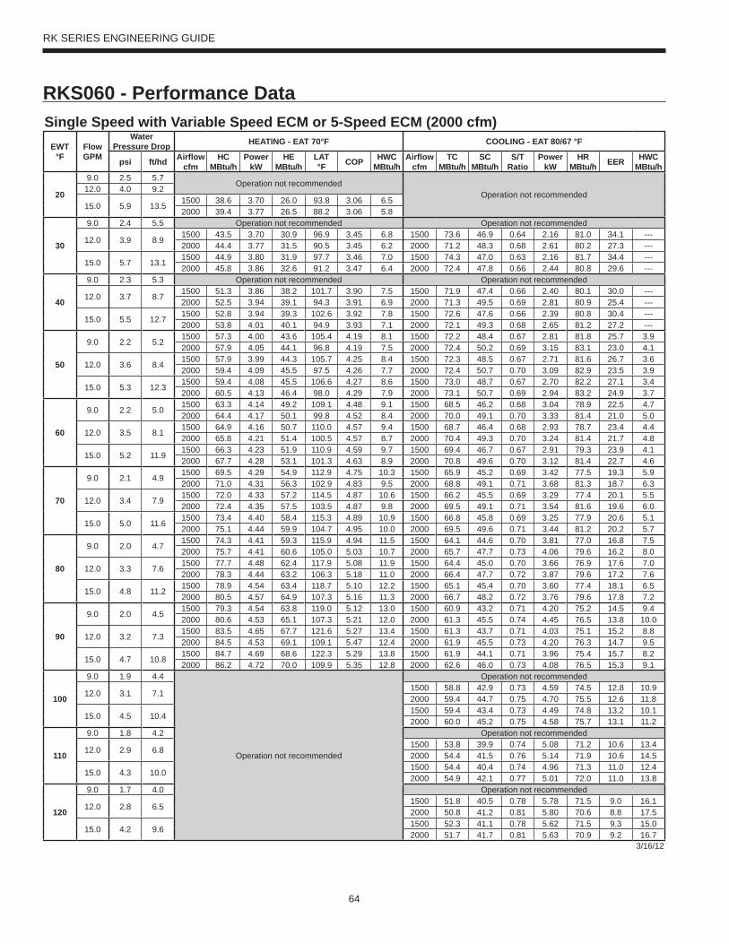
64
RK SERIES ENGINEERING GUIDE
RKS060 - Performance DataSingle Speed with Variable Speed ECM or 5-Speed ECM (2000 cfm)
EWT°F
Flow GPM
WaterPressure Drop HEATING - EAT 70°F COOLING - EAT 80/67 °F
psi ft/hd Airfl ow cfm
HC MBtu/h
Power kW
HE MBtu/h
LAT °F COP HWC
MBtu/hAirfl ow
cfmTC
MBtu/hSC
MBtu/hS/T
RatioPower
kWHR
MBtu/h EER HWC MBtu/h
20
9.0 2.5 5.7Operation not recommended
Operation not recommended12.0 4.0 9.2
15.0 5.9 13.51500 38.6 3.70 26.0 93.8 3.06 6.52000 39.4 3.77 26.5 88.2 3.06 5.8
30
9.0 2.4 5.5 Operation not recommended Operation not recommended
12.0 3.9 8.91500 43.5 3.70 30.9 96.9 3.45 6.8 1500 73.6 46.9 0.64 2.16 81.0 34.1 ---2000 44.4 3.77 31.5 90.5 3.45 6.2 2000 71.2 48.3 0.68 2.61 80.2 27.3 ---
15.0 5.7 13.11500 44.9 3.80 31.9 97.7 3.46 7.0 1500 74.3 47.0 0.63 2.16 81.7 34.4 ---2000 45.8 3.86 32.6 91.2 3.47 6.4 2000 72.4 47.8 0.66 2.44 80.8 29.6 ---
40
9.0 2.3 5.3 Operation not recommended Operation not recommended
12.0 3.7 8.71500 51.3 3.86 38.2 101.7 3.90 7.5 1500 71.9 47.4 0.66 2.40 80.1 30.0 ---2000 52.5 3.94 39.1 94.3 3.91 6.9 2000 71.3 49.5 0.69 2.81 80.9 25.4 ---
15.0 5.5 12.71500 52.8 3.94 39.3 102.6 3.92 7.8 1500 72.6 47.6 0.66 2.39 80.8 30.4 ---2000 53.8 4.01 40.1 94.9 3.93 7.1 2000 72.1 49.3 0.68 2.65 81.2 27.2 ---
50
9.0 2.2 5.21500 57.3 4.00 43.6 105.4 4.19 8.1 1500 72.2 48.4 0.67 2.81 81.8 25.7 3.92000 57.9 4.05 44.1 96.8 4.19 7.5 2000 72.4 50.2 0.69 3.15 83.1 23.0 4.1
12.0 3.6 8.41500 57.9 3.99 44.3 105.7 4.25 8.4 1500 72.3 48.5 0.67 2.71 81.6 26.7 3.62000 59.4 4.09 45.5 97.5 4.26 7.7 2000 72.4 50.7 0.70 3.09 82.9 23.5 3.9
15.0 5.3 12.31500 59.4 4.08 45.5 106.6 4.27 8.6 1500 73.0 48.7 0.67 2.70 82.2 27.1 3.42000 60.5 4.13 46.4 98.0 4.29 7.9 2000 73.1 50.7 0.69 2.94 83.2 24.9 3.7
60
9.0 2.2 5.01500 63.3 4.14 49.2 109.1 4.48 9.1 1500 68.5 46.2 0.68 3.04 78.9 22.5 4.72000 64.4 4.17 50.1 99.8 4.52 8.4 2000 70.0 49.1 0.70 3.33 81.4 21.0 5.0
12.0 3.5 8.11500 64.9 4.16 50.7 110.0 4.57 9.4 1500 68.7 46.4 0.68 2.93 78.7 23.4 4.42000 65.8 4.21 51.4 100.5 4.57 8.7 2000 70.4 49.3 0.70 3.24 81.4 21.7 4.8
15.0 5.2 11.91500 66.3 4.23 51.9 110.9 4.59 9.7 1500 69.4 46.7 0.67 2.91 79.3 23.9 4.12000 67.7 4.28 53.1 101.3 4.63 8.9 2000 70.8 49.6 0.70 3.12 81.4 22.7 4.6
70
9.0 2.1 4.91500 69.5 4.29 54.9 112.9 4.75 10.3 1500 65.9 45.2 0.69 3.42 77.5 19.3 5.92000 71.0 4.31 56.3 102.9 4.83 9.5 2000 68.8 49.1 0.71 3.68 81.3 18.7 6.3
12.0 3.4 7.91500 72.0 4.33 57.2 114.5 4.87 10.6 1500 66.2 45.5 0.69 3.29 77.4 20.1 5.52000 72.4 4.35 57.5 103.5 4.87 9.8 2000 69.5 49.1 0.71 3.54 81.6 19.6 6.0
15.0 5.0 11.61500 73.4 4.40 58.4 115.3 4.89 10.9 1500 66.8 45.8 0.69 3.25 77.9 20.6 5.12000 75.1 4.44 59.9 104.7 4.95 10.0 2000 69.5 49.6 0.71 3.44 81.2 20.2 5.7
80
9.0 2.0 4.71500 74.3 4.41 59.3 115.9 4.94 11.5 1500 64.1 44.6 0.70 3.81 77.0 16.8 7.52000 75.7 4.41 60.6 105.0 5.03 10.7 2000 65.7 47.7 0.73 4.06 79.6 16.2 8.0
12.0 3.3 7.61500 77.7 4.48 62.4 117.9 5.08 11.9 1500 64.4 45.0 0.70 3.66 76.9 17.6 7.02000 78.3 4.44 63.2 106.3 5.18 11.0 2000 66.4 47.7 0.72 3.87 79.6 17.2 7.6
15.0 4.8 11.21500 78.9 4.54 63.4 118.7 5.10 12.2 1500 65.1 45.4 0.70 3.60 77.4 18.1 6.52000 80.5 4.57 64.9 107.3 5.16 11.3 2000 66.7 48.2 0.72 3.76 79.6 17.8 7.2
90
9.0 2.0 4.51500 79.3 4.54 63.8 119.0 5.12 13.0 1500 60.9 43.2 0.71 4.20 75.2 14.5 9.42000 80.6 4.53 65.1 107.3 5.21 12.0 2000 61.3 45.5 0.74 4.45 76.5 13.8 10.0
12.0 3.2 7.31500 83.5 4.65 67.7 121.6 5.27 13.4 1500 61.3 43.7 0.71 4.03 75.1 15.2 8.82000 84.5 4.53 69.1 109.1 5.47 12.4 2000 61.9 45.5 0.73 4.20 76.3 14.7 9.5
15.0 4.7 10.81500 84.7 4.69 68.6 122.3 5.29 13.8 1500 61.9 44.1 0.71 3.96 75.4 15.7 8.22000 86.2 4.72 70.0 109.9 5.35 12.8 2000 62.6 46.0 0.73 4.08 76.5 15.3 9.1
100
9.0 1.9 4.4
Operation not recommended
Operation not recommended
12.0 3.1 7.11500 58.8 42.9 0.73 4.59 74.5 12.8 10.92000 59.4 44.7 0.75 4.70 75.5 12.6 11.8
15.0 4.5 10.41500 59.4 43.4 0.73 4.49 74.8 13.2 10.12000 60.0 45.2 0.75 4.58 75.7 13.1 11.2
110
9.0 1.8 4.2 Operation not recommended
12.0 2.9 6.81500 53.8 39.9 0.74 5.08 71.2 10.6 13.42000 54.4 41.5 0.76 5.14 71.9 10.6 14.5
15.0 4.3 10.01500 54.4 40.4 0.74 4.96 71.3 11.0 12.42000 54.9 42.1 0.77 5.01 72.0 11.0 13.8
120
9.0 1.7 4.0 Operation not recommended
12.0 2.8 6.51500 51.8 40.5 0.78 5.78 71.5 9.0 16.12000 50.8 41.2 0.81 5.80 70.6 8.8 17.5
15.0 4.2 9.61500 52.3 41.1 0.78 5.62 71.5 9.3 15.02000 51.7 41.7 0.81 5.63 70.9 9.2 16.7
3/16/12
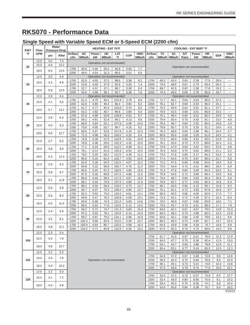
65
RK SERIES ENGINEERING GUIDE
RKS070 - Performance DataSingle Speed with Variable Speed ECM or 5-Speed ECM (2200 cfm)
EWT°F
Flow GPM
WaterPressure Drop HEATING - EAT 70°F COOLING - EAT 80/67 °F
psi ft/hd Airfl ow cfm
HC MBtu/h
Power kW
HE MBtu/h
LAT °F COP HWC
MBtu/hAirfl ow
cfmTC
MBtu/hSC
MBtu/hS/T
RatioPower
kWHR
MBtu/h EER HWC MBtu/h
20
12.0 3.0 7.0Operation not recommended
Operation not recommended15.0 4.4 10.2
18.0 6.0 13.91700 45.6 4.45 30.4 94.8 3.00 7.72200 46.6 4.54 31.2 89.6 3.01 6.9
30
12.0 3.0 6.8 Operation not recommendedcommended Operation not recommended
15.0 4.3 9.91700 52.5 4.55 37.0 98.6 3.38 8.1 1700 69.3 43.4 0.63 2.39 77.5 29.0 ---2200 53.8 4.65 37.9 92.6 3.39 7.4 2200 73.9 49.6 0.67 2.79 83.4 26.5 ---
18.0 5.8 13.51700 52.7 4.57 37.1 98.7 3.38 8.4 1700 69.7 42.9 0.62 2.38 77.8 29.3 ---2200 54.0 4.66 38.1 92.7 3.39 7.6 2200 74.3 49.0 0.66 2.78 83.8 26.7 ---
40
12.0 2.9 6.6 Operation not recommended Operation not recommended
15.0 4.1 9.61700 61.3 4.75 45.1 103.4 3.78 8.9 1700 71.7 46.1 0.64 2.63 80.6 27.3 ---2200 62.8 4.80 46.4 96.4 3.83 8.2 2200 76.1 52.7 0.69 3.03 86.4 25.1 ---
18.0 5.7 13.11700 61.7 4.77 45.4 103.6 3.79 9.2 1700 72.2 45.9 0.64 2.61 81.1 27.7 ---2200 63.2 4.82 46.7 96.6 3.84 8.4 2200 76.6 52.5 0.68 3.01 86.9 25.5 ---
50
12.0 2.8 6.41700 67.6 4.89 50.9 106.8 4.05 9.7 1700 75.1 48.4 0.64 3.01 85.4 24.9 4.32200 69.2 4.91 52.4 99.1 4.13 8.9 2200 79.4 55.4 0.70 3.43 91.1 23.2 4.5
15.0 4.0 9.31700 68.9 4.94 52.1 107.5 4.09 10.0 1700 75.5 48.7 0.64 2.92 85.5 25.8 4.02200 70.6 4.95 53.7 99.7 4.18 9.2 2200 79.8 55.7 0.70 3.33 91.2 24.0 4.3
18.0 5.5 12.71700 69.5 4.97 52.6 107.9 4.10 10.3 1700 76.3 48.9 0.64 2.89 86.1 26.4 3.72200 71.3 4.98 54.3 100.0 4.20 9.4 2200 80.6 55.9 0.69 3.29 91.9 24.5 4.1
60
12.0 2.7 6.21700 74.9 5.09 57.5 110.8 4.31 10.8 1700 72.3 46.9 0.65 3.31 83.5 21.8 5.22200 76.8 5.06 59.5 102.3 4.45 10.0 2200 76.1 53.6 0.70 3.72 88.8 20.4 5.5
15.0 3.9 9.01700 77.1 5.16 59.5 112.0 4.38 11.2 1700 72.6 47.0 0.65 3.22 83.5 22.6 4.82200 79.1 5.12 61.6 103.3 4.53 10.3 2200 76.4 53.8 0.70 3.62 88.8 21.1 5.2
18.0 5.3 12.31700 78.0 5.20 60.2 112.5 4.39 11.5 1700 73.5 47.6 0.65 3.17 84.3 23.2 4.52200 80.0 5.15 62.4 103.7 4.55 10.6 2200 77.4 54.5 0.70 3.57 89.5 21.7 5.0
70
12.0 2.6 6.01700 82.6 5.30 64.5 115.0 4.57 12.2 1700 72.0 47.5 0.66 3.69 84.6 19.5 6.52200 84.8 5.22 66.9 105.7 4.76 11.3 2200 75.5 54.4 0.72 4.11 89.5 18.4 6.9
15.0 3.8 8.71700 85.6 5.40 67.2 116.6 4.65 12.6 1700 72.3 47.6 0.66 3.59 84.5 20.2 6.12200 87.9 5.30 69.8 107.0 4.86 11.6 2200 75.8 54.5 0.72 3.99 89.4 19.0 6.6
18.0 5.1 11.91700 86.8 5.44 68.2 117.3 4.67 13.0 1700 73.4 48.7 0.66 3.53 85.4 20.8 5.62200 89.1 5.34 70.9 107.5 4.89 11.9 2200 76.9 55.7 0.72 3.93 90.3 19.6 6.3
80
12.0 2.5 5.81700 88.2 5.50 69.4 118.0 4.70 13.7 1700 69.1 45.5 0.66 4.12 83.1 16.8 8.22200 90.7 5.37 72.3 108.2 4.95 12.7 2200 72.1 52.1 0.72 4.53 87.6 15.9 8.7
15.0 3.6 8.41700 92.2 5.62 73.0 120.2 4.81 14.1 1700 69.3 45.5 0.66 4.00 82.9 17.3 7.72200 94.8 5.47 76.2 109.9 5.08 13.1 2200 72.4 52.1 0.72 4.40 87.4 16.4 8.3
18.0 5.0 11.51700 93.6 5.68 74.3 121.0 4.83 14.6 1700 70.5 46.9 0.67 3.92 83.9 18.0 7.12200 96.5 5.52 77.6 110.6 5.12 13.5 2200 73.6 53.7 0.73 4.31 88.3 17.1 7.9
90
12.0 2.4 5.61700 94.2 5.72 74.7 121.3 4.83 15.4 1700 63.4 42.2 0.67 4.57 79.0 13.9 10.32200 97.0 5.53 78.1 110.8 5.14 14.3 2200 66.0 48.4 0.73 4.98 83.0 13.3 10.9
15.0 3.5 8.11700 99.2 5.87 79.2 124.1 4.96 15.9 1700 63.6 42.1 0.66 4.45 78.8 14.3 9.62200 102.2 5.66 82.9 113.0 5.29 14.7 2200 66.2 48.3 0.73 4.84 82.7 13.7 10.4
18.0 4.8 11.11700 100.9 5.93 80.7 125.0 4.99 16.4 1700 64.9 43.8 0.68 4.35 79.7 14.9 8.92200 104.2 5.71 84.8 113.9 5.35 15.2 2200 67.5 50.3 0.74 4.73 83.6 14.3 9.9
100
12.0 2.3 5.4
Operation not recommended
Operation not recommended
15.0 3.4 7.81700 61.7 41.6 0.67 5.01 78.9 12.3 12.02200 64.0 47.7 0.75 5.39 82.4 11.9 13.0
18.0 4.6 10.71700 63.1 43.7 0.69 4.88 79.8 12.9 11.12200 65.4 50.1 0.77 5.24 83.3 12.5 12.3
110
12.0 2.2 5.2 Operation not recommended
15.0 3.3 7.51700 54.8 37.0 0.67 5.58 73.8 9.8 14.62200 56.5 42.4 0.75 5.94 76.8 9.5 15.9
18.0 4.4 10.21700 56.1 39.1 0.70 5.41 74.6 10.4 13.62200 57.9 44.9 0.78 5.76 77.6 10.0 15.1
120
12.0 2.2 5.0 Operation not recommended
15.0 3.1 7.21700 52.0 37.4 0.72 6.27 73.4 8.3 17.72200 53.4 43.0 0.80 6.60 76.0 8.1 19.2
18.0 4.3 9.81700 53.4 40.0 0.75 6.06 74.1 8.8 16.42200 54.9 45.9 0.84 6.38 76.7 8.6 18.2
3/16/12
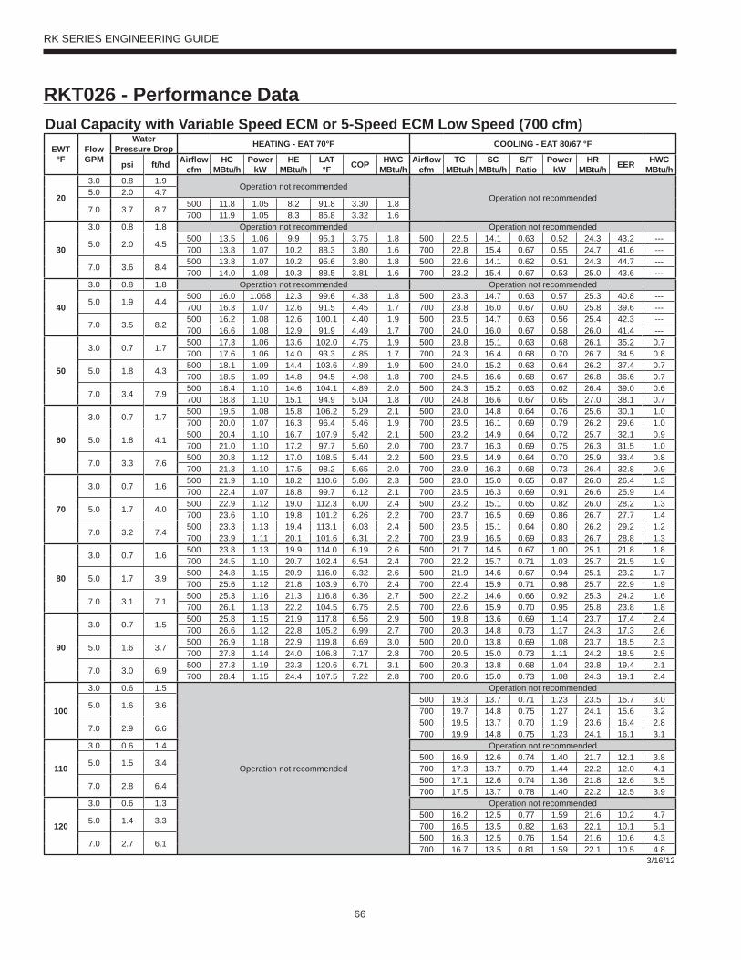
66
RK SERIES ENGINEERING GUIDE
RKT026 - Performance DataDual Capacity with Variable Speed ECM or 5-Speed ECM Low Speed (700 cfm)
EWT°F
Flow GPM
WaterPressure Drop HEATING - EAT 70°F COOLING - EAT 80/67 °F
psi ft/hd Airfl ow cfm
HC MBtu/h
Power kW
HE MBtu/h
LAT °F COP HWC
MBtu/hAirfl ow
cfmTC
MBtu/hSC
MBtu/hS/T
RatioPower
kWHR
MBtu/h EER HWC MBtu/h
20
3.0 0.8 1.9Operation not recommended
Operation not recommended5.0 2.0 4.7
7.0 3.7 8.7500 11.8 1.05 8.2 91.8 3.30 1.8700 11.9 1.05 8.3 85.8 3.32 1.6
30
3.0 0.8 1.8 Operation not recommended Operation not recommended
5.0 2.0 4.5500 13.5 1.06 9.9 95.1 3.75 1.8 500 22.5 14.1 0.63 0.52 24.3 43.2 ---700 13.8 1.07 10.2 88.3 3.80 1.6 700 22.8 15.4 0.67 0.55 24.7 41.6 ---
7.0 3.6 8.4500 13.8 1.07 10.2 95.6 3.80 1.8 500 22.6 14.1 0.62 0.51 24.3 44.7 ---700 14.0 1.08 10.3 88.5 3.81 1.6 700 23.2 15.4 0.67 0.53 25.0 43.6 ---
40
3.0 0.8 1.8 Operation not recommended Operation not recommended
5.0 1.9 4.4500 16.0 1.068 12.3 99.6 4.38 1.8 500 23.3 14.7 0.63 0.57 25.3 40.8 ---700 16.3 1.07 12.6 91.5 4.45 1.7 700 23.8 16.0 0.67 0.60 25.8 39.6 ---
7.0 3.5 8.2500 16.2 1.08 12.6 100.1 4.40 1.9 500 23.5 14.7 0.63 0.56 25.4 42.3 ---700 16.6 1.08 12.9 91.9 4.49 1.7 700 24.0 16.0 0.67 0.58 26.0 41.4 ---
50
3.0 0.7 1.7500 17.3 1.06 13.6 102.0 4.75 1.9 500 23.8 15.1 0.63 0.68 26.1 35.2 0.7700 17.6 1.06 14.0 93.3 4.85 1.7 700 24.3 16.4 0.68 0.70 26.7 34.5 0.8
5.0 1.8 4.3500 18.1 1.09 14.4 103.6 4.89 1.9 500 24.0 15.2 0.63 0.64 26.2 37.4 0.7700 18.5 1.09 14.8 94.5 4.98 1.8 700 24.5 16.6 0.68 0.67 26.8 36.6 0.7
7.0 3.4 7.9500 18.4 1.10 14.6 104.1 4.89 2.0 500 24.3 15.2 0.63 0.62 26.4 39.0 0.6700 18.8 1.10 15.1 94.9 5.04 1.8 700 24.8 16.6 0.67 0.65 27.0 38.1 0.7
60
3.0 0.7 1.7500 19.5 1.08 15.8 106.2 5.29 2.1 500 23.0 14.8 0.64 0.76 25.6 30.1 1.0700 20.0 1.07 16.3 96.4 5.46 1.9 700 23.5 16.1 0.69 0.79 26.2 29.6 1.0
5.0 1.8 4.1500 20.4 1.10 16.7 107.9 5.42 2.1 500 23.2 14.9 0.64 0.72 25.7 32.1 0.9700 21.0 1.10 17.2 97.7 5.60 2.0 700 23.7 16.3 0.69 0.75 26.3 31.5 1.0
7.0 3.3 7.6500 20.8 1.12 17.0 108.5 5.44 2.2 500 23.5 14.9 0.64 0.70 25.9 33.4 0.8700 21.3 1.10 17.5 98.2 5.65 2.0 700 23.9 16.3 0.68 0.73 26.4 32.8 0.9
70
3.0 0.7 1.6500 21.9 1.10 18.2 110.6 5.86 2.3 500 23.0 15.0 0.65 0.87 26.0 26.4 1.3700 22.4 1.07 18.8 99.7 6.12 2.1 700 23.5 16.3 0.69 0.91 26.6 25.9 1.4
5.0 1.7 4.0500 22.9 1.12 19.0 112.3 6.00 2.4 500 23.2 15.1 0.65 0.82 26.0 28.2 1.3700 23.6 1.10 19.8 101.2 6.26 2.2 700 23.7 16.5 0.69 0.86 26.7 27.7 1.4
7.0 3.2 7.4500 23.3 1.13 19.4 113.1 6.03 2.4 500 23.5 15.1 0.64 0.80 26.2 29.2 1.2700 23.9 1.11 20.1 101.6 6.31 2.2 700 23.9 16.5 0.69 0.83 26.7 28.8 1.3
80
3.0 0.7 1.6500 23.8 1.13 19.9 114.0 6.19 2.6 500 21.7 14.5 0.67 1.00 25.1 21.8 1.8700 24.5 1.10 20.7 102.4 6.54 2.4 700 22.2 15.7 0.71 1.03 25.7 21.5 1.9
5.0 1.7 3.9500 24.8 1.15 20.9 116.0 6.32 2.6 500 21.9 14.6 0.67 0.94 25.1 23.2 1.7700 25.6 1.12 21.8 103.9 6.70 2.4 700 22.4 15.9 0.71 0.98 25.7 22.9 1.9
7.0 3.1 7.1500 25.3 1.16 21.3 116.8 6.36 2.7 500 22.2 14.6 0.66 0.92 25.3 24.2 1.6700 26.1 1.13 22.2 104.5 6.75 2.5 700 22.6 15.9 0.70 0.95 25.8 23.8 1.8
90
3.0 0.7 1.5500 25.8 1.15 21.9 117.8 6.56 2.9 500 19.8 13.6 0.69 1.14 23.7 17.4 2.4700 26.6 1.12 22.8 105.2 6.99 2.7 700 20.3 14.8 0.73 1.17 24.3 17.3 2.6
5.0 1.6 3.7500 26.9 1.18 22.9 119.8 6.69 3.0 500 20.0 13.8 0.69 1.08 23.7 18.5 2.3700 27.8 1.14 24.0 106.8 7.17 2.8 700 20.5 15.0 0.73 1.11 24.2 18.5 2.5
7.0 3.0 6.9500 27.3 1.19 23.3 120.6 6.71 3.1 500 20.3 13.8 0.68 1.04 23.8 19.4 2.1700 28.4 1.15 24.4 107.5 7.22 2.8 700 20.6 15.0 0.73 1.08 24.3 19.1 2.4
100
3.0 0.6 1.5
Operation not recommended
Operation not recommended
5.0 1.6 3.6500 19.3 13.7 0.71 1.23 23.5 15.7 3.0700 19.7 14.8 0.75 1.27 24.1 15.6 3.2
7.0 2.9 6.6500 19.5 13.7 0.70 1.19 23.6 16.4 2.8700 19.9 14.8 0.75 1.23 24.1 16.1 3.1
110
3.0 0.6 1.4 Operation not recommended
5.0 1.5 3.4500 16.9 12.6 0.74 1.40 21.7 12.1 3.8700 17.3 13.7 0.79 1.44 22.2 12.0 4.1
7.0 2.8 6.4500 17.1 12.6 0.74 1.36 21.8 12.6 3.5700 17.5 13.7 0.78 1.40 22.2 12.5 3.9
120
3.0 0.6 1.3 Operation not recommended
5.0 1.4 3.3500 16.2 12.5 0.77 1.59 21.6 10.2 4.7700 16.5 13.5 0.82 1.63 22.1 10.1 5.1
7.0 2.7 6.1500 16.3 12.5 0.76 1.54 21.6 10.6 4.3700 16.7 13.5 0.81 1.59 22.1 10.5 4.8
3/16/12

67
RK SERIES ENGINEERING GUIDE
RKT026 - Performance DataDual Capacity with Variable Speed ECM or 5-Speed ECM High Speed (900 cfm)
EWT°F
Flow GPM
WaterPressure Drop HEATING - EAT 70°F COOLING - EAT 80/67 °F
psi ft/hd Airfl ow cfm
HC MBtu/h
Power kW
HE MBtu/h
LAT °F COP HWC
MBtu/hAirfl ow
cfmTC
MBtu/hSC
MBtu/hS/T
RatioPower
kWHR
MBtu/h EER HWC MBtu/h
20
4.0 1.4 3.2Operation not recommended
Operation not recommended6.0 2.9 6.6
8.0 4.8 11.1700 16.2 1.40 11.4 91.5 3.40 2.1900 16.4 1.41 11.6 86.9 3.41 1.9
30
4.0 1.4 3.2 Operation not recommended Operation not recommended
6.0 2.8 6.4700 18.6 1.44 13.7 94.6 3.79 2.3 700 29.8 18.6 0.62 0.93 33.0 32.1 ---900 19.0 1.45 14.0 89.5 3.83 2.1 900 30.3 20.3 0.67 0.98 33.6 31.0 ---
8.0 4.7 10.8700 19.0 1.45 14.0 95.1 3.83 2.3 700 30.0 18.6 0.62 0.90 33.0 33.3 ---900 19.2 1.46 14.3 89.8 3.85 2.1 900 30.7 20.3 0.66 0.95 33.9 32.5 ---
40
4.0 1.3 3.1 Operation not recommended Operation not recommended
6.0 2.7 6.2700 21.6 1.50 16.5 98.6 4.24 2.5 700 30.2 19.1 0.63 1.01 33.7 29.9 ---900 22.1 1.50 16.9 92.7 4.30 2.3 900 30.8 20.8 0.68 1.06 34.4 29.1 ---
8.0 4.5 10.4700 22.0 1.51 16.8 99.1 4.26 2.6 700 30.5 19.1 0.63 0.98 33.8 31.1 ---900 22.4 1.51 17.3 93.1 4.34 2.4 900 31.2 20.8 0.67 1.02 34.7 30.4 ---
50
4.0 1.3 3.0700 23.4 1.53 18.1 100.9 4.46 2.7 700 30.0 19.3 0.64 1.18 34.0 25.5 1.3900 23.8 1.53 18.6 94.5 4.55 2.5 900 30.7 21.0 0.69 1.22 34.8 25.1 1.4
6.0 2.6 6.0700 24.5 1.57 19.2 102.5 4.59 2.8 700 30.3 19.5 0.64 1.12 34.2 27.1 1.3900 25.0 1.57 19.7 95.7 4.67 2.6 900 31.0 21.3 0.69 1.16 34.9 26.6 1.4
8.0 4.4 10.1700 24.9 1.59 19.5 102.9 4.59 2.9 700 30.7 19.5 0.64 1.08 34.4 28.3 1.2900 25.5 1.58 20.1 96.2 4.73 2.7 900 31.3 21.3 0.68 1.13 35.1 27.7 1.3
60
4.0 1.2 2.9700 26.3 1.62 20.8 104.8 4.77 3.1 700 29.7 19.2 0.65 1.28 34.0 23.2 1.6900 26.9 1.60 21.4 97.6 4.93 2.9 900 30.3 20.9 0.69 1.33 34.8 22.8 1.7
6.0 2.5 5.8700 27.5 1.65 21.9 106.4 4.89 3.2 700 30.0 19.4 0.65 1.21 34.1 24.7 1.5900 28.2 1.64 22.6 99.0 5.05 2.9 900 30.6 21.1 0.69 1.26 34.9 24.3 1.6
8.0 4.2 9.8700 28.0 1.67 22.3 107.0 4.91 3.3 700 30.3 19.4 0.64 1.18 34.3 25.7 1.4900 28.7 1.65 23.1 99.5 5.10 3.0 900 30.9 21.1 0.68 1.22 35.1 25.3 1.6
70
4.0 1.2 2.8700 29.3 1.70 23.5 108.8 5.05 3.5 700 29.3 19.1 0.65 1.42 34.2 20.6 2.0900 30.0 1.67 24.3 100.9 5.28 3.2 900 29.9 20.8 0.69 1.48 34.9 20.2 2.1
6.0 2.4 5.6700 30.6 1.73 24.7 110.5 5.17 3.6 700 29.6 19.3 0.65 1.34 34.1 22.0 1.9900 31.5 1.71 25.7 102.5 5.40 3.3 900 30.2 21.0 0.69 1.40 35.0 21.6 2.0
8.0 4.1 9.5700 31.2 1.76 25.2 111.3 5.20 3.7 700 29.9 19.3 0.64 1.31 34.4 22.8 1.7900 32.0 1.72 26.1 102.9 5.44 3.4 900 30.5 21.0 0.69 1.35 35.1 22.5 1.9
80
4.0 1.2 2.7700 32.0 1.80 25.8 112.3 5.20 3.9 700 28.2 18.8 0.67 1.57 33.5 17.9 2.5900 32.9 1.76 26.9 103.9 5.48 3.6 900 28.7 20.4 0.71 1.63 34.3 17.6 2.7
6.0 2.4 5.4700 33.4 1.84 27.1 114.2 5.31 4.0 700 28.4 18.9 0.67 1.49 33.5 19.0 2.3900 34.5 1.80 28.4 105.5 5.62 3.7 900 29.0 20.6 0.71 1.54 34.3 18.9 2.5
8.0 4.0 9.2700 34.0 1.87 27.6 114.9 5.33 4.1 700 28.7 18.9 0.66 1.45 33.7 19.9 2.2900 35.1 1.82 28.9 106.1 5.66 3.8 900 29.3 20.6 0.70 1.50 34.4 19.6 2.4
90
4.0 1.1 2.6700 34.8 1.91 28.2 116.0 5.33 4.3 700 26.7 18.1 0.68 1.74 32.6 15.3 3.1900 35.9 1.86 29.6 107.0 5.67 4.0 900 27.3 19.7 0.72 1.79 33.4 15.2 3.3
6.0 2.3 5.2700 36.3 1.96 29.6 118.0 5.43 4.5 700 26.9 18.4 0.68 1.65 32.5 16.3 2.9900 37.6 1.89 31.1 108.6 5.82 4.1 900 27.5 19.9 0.72 1.69 33.3 16.3 3.2
8.0 3.8 8.8700 36.9 1.98 30.1 118.8 5.45 4.6 700 27.3 18.4 0.67 1.59 32.7 17.1 2.7900 38.3 1.91 31.7 109.4 5.86 4.3 900 27.8 19.9 0.72 1.65 33.4 16.8 3.0
100
4.0 1.1 2.5
Operation not recommended
Operation not recommended
6.0 2.2 5.1700 25.6 17.8 0.70 1.85 31.9 13.8 3.6900 26.1 19.3 0.74 1.90 32.6 13.8 3.9
8.0 3.7 8.5700 25.9 17.8 0.69 1.79 32.0 14.5 3.3900 26.4 19.3 0.73 1.85 32.7 14.3 3.7
110
4.0 1.0 2.4 Operation not recommended
6.0 2.1 4.9700 23.4 16.8 0.72 2.04 30.4 11.5 4.4900 23.9 18.2 0.76 2.10 31.1 11.4 4.7
8.0 3.5 8.2700 23.7 16.8 0.71 1.98 30.4 12.0 4.1900 24.2 18.2 0.76 2.04 31.1 11.8 4.5
120
4.0 1.0 2.3 Operation not recommended
6.0 2.0 4.7700 21.7 16.1 0.74 2.29 29.5 9.5 5.3900 22.1 17.5 0.79 2.35 30.1 9.4 5.7
8.0 3.4 7.9700 21.9 16.1 0.74 2.21 29.4 9.9 4.9900 22.3 17.5 0.78 2.28 30.1 9.8 5.4
3/16/12

68
RK SERIES ENGINEERING GUIDE
RKT038 - Performance DataDual Capacity with Variable Speed ECM or 5-Speed ECM Low Speed (1050 cfm)
EWT°F
Flow GPM
WaterPressure Drop HEATING - EAT 70°F COOLING - EAT 80/67 °F
PSI ft/hd Airfl ow cfm
HC MBtu/h
Power kW
HE MBtu/h
LAT °F COP HWC
MBtu/hAirfl ow
cfmTC
MBtu/hSC
MBtu/hS/T
RatioPower
kWHR
MBtu/h EER HWC MBtu/h
20
4.0 0.9 2.1Operation not recommended
Operation not recommended6.0 1.7 4.0
8.0 2.9 6.7900 15.1 1.40 10.3 85.5 3.17 2.51050 15.7 1.43 10.8 83.9 3.22 2.3
30
4.0 0.9 2.0 Operation not recommended Operation not recommended
6.0 1.7 3.9900 16.8 1.38 12.1 87.3 3.56 2.4 900 29.1 18.4 0.63 0.74 31.6 39.3 ---1050 17.5 1.42 12.6 85.4 3.61 2.2 1050 29.9 20.4 0.68 0.75 32.5 39.6 ---
8.0 2.8 6.5900 17.9 1.42 13.0 88.4 3.69 2.5 900 29.6 18.9 0.64 0.73 32.1 40.3 ---1050 18.6 1.45 13.6 86.4 3.75 2.3 1050 30.4 20.9 0.69 0.75 33.0 40.6 ---
40
4.0 0.8 1.9 Operation not recommended Operation not recommended
6.0 1.6 3.8900 19.8 1.41 15.0 90.4 4.13 2.5 900 30.3 19.7 0.65 0.80 33.0 37.8 ---1050 20.5 1.44 15.6 88.1 4.19 2.3 1050 31.1 21.8 0.70 0.82 33.9 38.1 ---
8.0 2.7 6.3900 20.9 1.44 16.0 91.5 4.24 2.6 900 30.8 20.2 0.66 0.79 33.5 38.8 ---1050 21.6 1.47 16.6 89.1 4.31 2.4 1050 31.7 22.4 0.71 0.81 34.4 39.1 ---
50
4.0 0.8 1.9900 21.8 1.43 16.9 92.5 4.46 2.6 900 31.3 21.1 0.67 0.91 34.4 34.3 1.01050 22.5 1.45 17.6 89.8 4.54 2.4 1050 32.2 23.4 0.73 0.93 35.3 34.6 1.1
6.0 1.6 3.7900 22.6 1.43 17.7 93.2 4.62 2.7 900 31.6 21.2 0.67 0.89 34.6 35.5 0.91050 23.3 1.45 18.3 90.5 4.70 2.5 1050 32.5 23.5 0.72 0.91 35.6 35.8 1.0
8.0 2.6 6.1900 23.7 1.47 18.6 94.3 4.72 2.8 900 32.1 21.8 0.68 0.88 35.1 36.4 0.91050 24.4 1.49 19.3 91.5 4.81 2.5 1050 33.0 24.1 0.73 0.90 36.1 36.7 1.0
60
4.0 0.8 1.8900 24.6 1.46 19.6 95.3 4.94 2.9 900 30.1 20.3 0.68 1.02 33.5 29.5 1.31050 25.2 1.47 20.2 92.2 5.02 2.6 1050 30.9 22.5 0.73 1.04 34.4 29.7 1.4
6.0 1.5 3.6900 25.6 1.46 20.6 96.3 5.15 3.0 900 30.3 20.5 0.67 0.99 33.7 30.5 1.31050 26.2 1.47 21.2 93.1 5.24 2.7 1050 31.2 22.6 0.73 1.01 34.6 30.8 1.4
8.0 2.5 5.9900 26.5 1.49 21.4 97.3 5.21 3.0 900 30.8 21.0 0.68 0.98 34.2 31.3 1.21050 27.1 1.50 22.0 93.9 5.30 2.8 1050 31.7 23.2 0.73 1.00 35.1 31.6 1.3
70
4.0 0.8 1.8900 27.3 1.49 22.3 98.1 5.39 3.2 900 29.7 20.6 0.69 1.16 33.6 25.7 1.91050 27.9 1.49 22.8 94.6 5.49 2.9 1050 30.5 22.8 0.75 1.18 34.5 25.9 2.0
6.0 1.5 3.5900 28.5 1.48 23.5 99.4 5.65 3.3 900 29.9 20.7 0.69 1.13 33.8 26.6 1.71050 29.1 1.48 24.0 95.6 5.76 3.0 1050 30.8 23.0 0.75 1.15 34.7 26.8 1.9
8.0 2.5 5.7900 29.3 1.51 24.1 100.1 5.67 3.4 900 30.4 21.3 0.70 1.12 34.2 27.3 1.61050 29.8 1.51 24.6 96.3 5.78 3.1 1050 31.3 23.5 0.75 1.14 35.2 27.5 1.8
80
4.0 0.7 1.7900 29.9 1.51 24.8 100.8 5.79 3.6 900 28.6 20.2 0.71 1.32 33.1 21.7 2.51050 30.3 1.51 25.2 96.7 5.91 3.3 1050 29.4 22.4 0.76 1.34 33.9 21.9 2.7
6.0 1.4 3.3900 31.4 1.50 26.2 102.3 6.11 3.7 900 28.8 20.3 0.71 1.28 33.2 22.5 2.41050 31.7 1.49 26.6 98.0 6.23 3.4 1050 29.6 22.5 0.76 1.31 34.1 22.7 2.6
8.0 2.4 5.5900 31.8 1.54 26.6 102.7 6.07 3.8 900 29.3 20.8 0.71 1.27 33.6 23.0 2.21050 32.1 1.52 26.9 98.3 6.19 3.5 1050 30.1 23.1 0.77 1.30 34.5 23.2 2.5
90
4.0 0.7 1.6900 32.5 1.54 27.2 103.4 6.18 4.0 900 26.5 18.9 0.71 1.50 31.6 17.6 3.41050 32.7 1.52 27.5 98.9 6.31 3.7 1050 27.2 20.9 0.77 1.53 32.4 17.8 3.6
6.0 1.4 3.2900 34.1 1.53 28.9 105.1 6.56 4.2 900 26.7 19.0 0.71 1.46 31.7 18.3 3.21050 34.3 1.50 29.2 100.3 6.69 3.8 1050 27.4 21.0 0.77 1.49 32.5 18.4 3.4
8.0 2.3 5.3900 34.3 1.56 29.0 105.3 6.45 4.3 900 27.1 19.5 0.72 1.45 32.1 18.7 2.91050 34.4 1.53 29.2 100.4 6.59 4.0 1050 27.9 21.6 0.77 1.48 32.9 18.9 3.3
100
4.0 0.7 1.6
Operation not recommended
Operation not recommended
6.0 1.3 3.1900 25.8 19.3 0.75 1.67 31.5 15.4 4.1
1050 26.5 21.4 0.81 1.70 32.3 15.6 4.5
8.0 2.2 5.1900 26.2 19.8 0.76 1.65 31.8 15.8 3.8
1050 26.9 21.9 0.81 1.69 32.7 16.0 4.2
110
4.0 0.7 1.5 Operation not recommended
6.0 1.3 3.0900 23.1 18.1 0.79 1.90 29.6 12.2 5.2
1050 23.7 20.1 0.85 1.93 30.3 12.3 5.7
8.0 2.1 4.9900 23.5 18.6 0.79 1.88 29.9 12.5 4.8
1050 24.1 20.6 0.85 1.92 30.7 12.6 5.4
120
4.0 0.6 1.5 Operation not recommended
6.0 1.2 2.9900 21.9 18.0 0.82 2.15 29.2 10.2 6.5
1050 22.5 19.9 0.88 2.20 30.0 10.2 7.0
8.0 2.0 4.7900 22.2 18.4 0.83 2.13 29.5 10.4 6.0
1050 22.9 20.4 0.89 2.18 30.3 10.5 6.73/16/12
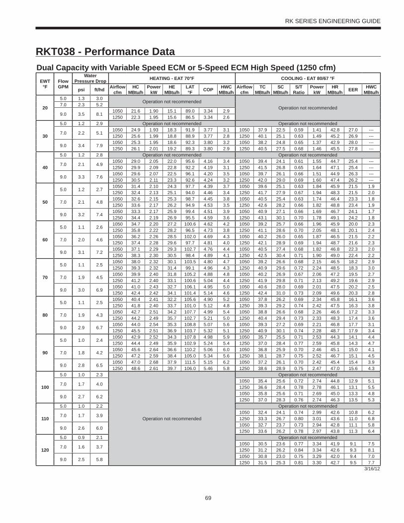
69
RK SERIES ENGINEERING GUIDE
RKT038 - Performance DataDual Capacity with Variable Speed ECM or 5-Speed ECM High Speed (1250 cfm)
EWT°F
Flow GPM
WaterPressure Drop HEATING - EAT 70°F COOLING - EAT 80/67 °F
psi ft/hd Airfl ow cfm
HC MBtu/h
Power kW
HE MBtu/h
LAT °F COP HWC
MBtu/hAirfl ow
cfmTC
MBtu/hSC
MBtu/hS/T
RatioPower
kWHR
MBtu/h EER HWC MBtu/h
20
5.0 1.3 3.0Operation not recommended
Operation not recommended7.0 2.3 5.2
9.0 3.5 8.11050 21.6 1.90 15.1 89.0 3.34 2.91250 22.3 1.95 15.6 86.5 3.34 2.6
30
5.0 1.2 2.9 Operation not recommended Operation not recommended
7.0 2.2 5.11050 24.9 1.93 18.3 91.9 3.77 3.1 1050 37.9 22.5 0.59 1.41 42.8 27.0 ---1250 25.6 1.99 18.8 88.9 3.77 2.8 1250 40.1 25.1 0.63 1.49 45.2 26.9 ---
9.0 3.4 7.91050 25.3 1.95 18.6 92.3 3.80 3.2 1050 38.2 24.8 0.65 1.37 42.9 28.0 ---1250 26.1 2.01 19.2 89.3 3.80 2.9 1250 40.5 27.5 0.68 1.46 45.5 27.8 ---
40
5.0 1.2 2.8 Operation not recommended Operation not recommended
7.0 2.1 4.91050 29.0 2.05 22.0 95.6 4.16 3.4 1050 39.4 24.1 0.61 1.55 44.7 25.4 ---1250 29.9 2.09 22.8 92.2 4.19 3.1 1250 41.5 26.8 0.65 1.64 47.1 25.4 ---
9.0 3.3 7.61050 29.6 2.07 22.5 96.1 4.20 3.5 1050 39.7 26.1 0.66 1.51 44.9 26.3 ---1250 30.5 2.11 23.3 92.6 4.24 3.2 1250 42.0 29.0 0.69 1.60 47.4 26.2 ---
50
5.0 1.2 2.71050 31.4 2.10 24.3 97.7 4.39 3.7 1050 39.6 25.1 0.63 1.84 45.9 21.5 1.91250 32.4 2.13 25.1 94.0 4.46 3.4 1250 41.7 27.9 0.67 1.94 48.3 21.5 2.0
7.0 2.1 4.81050 32.6 2.15 25.3 98.7 4.45 3.8 1050 40.5 25.4 0.63 1.74 46.4 23.3 1.81250 33.6 2.17 26.2 94.9 4.53 3.5 1250 42.6 28.2 0.66 1.82 48.8 23.4 1.9
9.0 3.2 7.41050 33.3 2.17 25.9 99.4 4.51 3.9 1050 40.9 27.1 0.66 1.69 46.7 24.1 1.71250 34.4 2.19 26.9 95.5 4.59 3.6 1250 43.1 30.1 0.70 1.78 49.1 24.2 1.8
60
5.0 1.1 2.61050 34.7 2.20 27.2 100.6 4.62 4.2 1050 39.2 25.7 0.66 1.96 45.9 20.0 2.31250 35.8 2.22 28.2 96.5 4.73 3.8 1250 41.1 28.6 0.70 2.05 48.1 20.1 2.4
7.0 2.0 4.61050 36.2 2.26 28.5 102.0 4.69 4.3 1050 40.2 26.0 0.65 1.87 46.5 21.5 2.21250 37.4 2.28 29.6 97.7 4.81 4.0 1250 42.1 28.9 0.69 1.94 48.7 21.6 2.3
9.0 3.1 7.21050 37.1 2.29 29.3 102.7 4.76 4.4 1050 40.5 27.4 0.68 1.82 46.8 22.3 2.01250 38.3 2.30 30.5 98.4 4.89 4.1 1250 42.5 30.4 0.71 1.90 49.0 22.4 2.2
70
5.0 1.1 2.51050 38.0 2.32 30.1 103.5 4.80 4.7 1050 39.2 26.6 0.68 2.15 46.5 18.2 2.91250 39.3 2.32 31.4 99.1 4.96 4.3 1250 40.9 29.6 0.72 2.24 48.5 18.3 3.0
7.0 1.9 4.51050 39.9 2.40 31.8 105.2 4.88 4.8 1050 40.2 26.9 0.67 2.06 47.2 19.5 2.71250 41.2 2.40 33.1 100.6 5.04 4.4 1250 41.9 29.8 0.71 2.13 49.2 19.6 2.9
9.0 3.0 6.91050 41.0 2.43 32.7 106.1 4.95 5.0 1050 40.6 28.0 0.69 2.01 47.5 20.2 2.51250 42.4 2.42 34.1 101.4 5.14 4.6 1250 42.4 31.0 0.73 2.09 49.6 20.3 2.8
80
5.0 1.1 2.51050 40.4 2.41 32.2 105.6 4.90 5.2 1050 37.8 26.2 0.69 2.34 45.8 16.1 3.61250 41.8 2.40 33.7 101.0 5.12 4.8 1250 39.3 29.2 0.74 2.42 47.5 16.3 3.8
7.0 1.9 4.31050 42.7 2.51 34.2 107.7 4.99 5.4 1050 38.8 26.6 0.68 2.26 46.6 17.2 3.31250 44.2 2.49 35.7 102.7 5.21 5.0 1250 40.4 29.4 0.73 2.33 48.3 17.4 3.6
9.0 2.9 6.71050 44.0 2.54 35.3 108.8 5.07 5.6 1050 39.3 27.2 0.69 2.21 46.8 17.7 3.11250 45.5 2.51 36.9 103.7 5.32 5.1 1250 40.9 30.1 0.74 2.28 48.7 17.9 3.4
90
5.0 1.0 2.41050 42.9 2.52 34.3 107.8 4.98 5.9 1050 35.7 25.5 0.71 2.53 44.3 14.1 4.41250 44.4 2.49 35.9 102.9 5.24 5.4 1250 37.0 28.4 0.77 2.59 45.8 14.3 4.7
7.0 1.8 4.21050 45.6 2.64 36.6 110.2 5.06 6.0 1050 36.8 25.9 0.70 2.46 45.1 15.0 4.11250 47.2 2.59 38.4 105.0 5.34 5.6 1250 38.1 28.7 0.75 2.52 46.7 15.1 4.5
9.0 2.8 6.51050 47.0 2.68 37.9 111.5 5.15 6.2 1050 37.2 26.1 0.70 2.42 45.4 15.4 3.91250 48.6 2.61 39.7 106.0 5.46 5.8 1250 38.6 28.9 0.75 2.47 47.0 15.6 4.3
100
5.0 1.0 2.3
Operation not recommended
Operation not recommended
7.0 1.7 4.01050 35.4 25.6 0.72 2.74 44.8 12.9 5.11250 36.6 28.4 0.78 2.78 46.1 13.1 5.5
9.0 2.7 6.21050 35.8 25.6 0.71 2.69 45.0 13.3 4.81250 37.0 28.3 0.76 2.74 46.3 13.5 5.3
110
5.0 1.0 2.2 Operation not recommended
7.0 1.7 3.91050 32.4 24.1 0.74 2.99 42.6 10.8 6.21250 33.3 26.7 0.80 3.01 43.6 11.0 6.8
9.0 2.6 6.01050 32.7 23.7 0.73 2.94 42.8 11.1 5.81250 33.6 26.2 0.78 2.97 43.8 11.3 6.4
120
5.0 0.9 2.1 Operation not recommended
7.0 1.6 3.71050 30.5 23.6 0.77 3.34 41.9 9.1 7.51250 31.2 26.2 0.84 3.34 42.6 9.3 8.1
9.0 2.5 5.81050 30.8 23.0 0.75 3.29 42.0 9.4 7.01250 31.5 25.3 0.81 3.30 42.7 9.5 7.7
3/16/12

70
RK SERIES ENGINEERING GUIDE
RKT049 - Performance DataDual Capacity with Variable Speed ECM or 5-Speed ECM Low Speed (1350 cfm)
EWT°F
Flow GPM
WaterPressure Drop HEATING - EAT 70°F COOLING - EAT 80/67 °F
psi ft/hd Airfl ow cfm
HC MBtu/h
Power kW
HE MBtu/h
LAT °F COP HWC
MBtu/hAirfl ow
cfmTC
MBtu/hSC
MBtu/hS/T
RatioPower
kWHR
MBtu/h EER HWC MBtu/h
20
5.0 0.9 2.2Operation not recommended
Operation not recommended8.0 2.0 4.6
11.0 3.4 7.81150 22.1 2.23 14.4 87.8 2.90 4.21350 22.9 2.26 15.1 85.7 2.96 3.8
30
5.0 0.9 2.1 Operation not recommended Operation not recommended
8.0 1.9 4.41150 25.4 2.28 17.7 90.5 3.27 4.3 1150 37.5 20.0 0.53 1.13 41.4 33.3 ---1350 26.2 2.29 18.4 88.0 3.35 3.9 1350 38.8 23.6 0.61 1.20 42.9 32.4 ---
11.0 3.3 7.61150 26.1 2.29 18.2 91.0 3.33 4.4 1150 37.6 19.9 0.53 1.05 41.2 35.7 ---1350 27.0 2.32 19.1 88.5 3.40 4.0 1350 38.6 23.5 0.61 1.12 42.4 34.5 ---
40
5.0 0.9 2.0 Operation not recommended Operation not recommended
8.0 1.9 4.31150 29.2 2.36 21.1 93.5 3.63 4.5 1150 39.6 21.8 0.55 1.24 43.9 31.9 ---1350 30.2 2.36 22.2 90.7 3.76 4.2 1350 40.9 25.7 0.63 1.31 45.4 31.3 ---
11.0 3.2 7.41150 30.1 2.37 22.0 94.3 3.72 4.7 1150 39.8 21.8 0.55 1.17 43.8 34.1 ---1350 31.2 2.39 23.0 91.4 3.82 4.2 1350 40.9 25.7 0.63 1.23 45.1 33.3 ---
50
5.0 0.9 2.01150 30.2 2.35 22.2 94.3 3.77 4.8 1150 40.4 23.3 0.58 1.60 45.9 25.2 1.61350 31.2 2.35 23.2 91.4 3.89 4.4 1350 41.7 27.5 0.66 1.67 47.4 24.9 1.7
8.0 1.8 4.21150 32.6 2.43 24.3 96.2 3.93 4.9 1150 41.3 23.4 0.57 1.39 46.0 29.8 1.51350 33.8 2.41 25.6 93.2 4.11 4.5 1350 42.5 27.6 0.65 1.45 47.5 29.2 1.6
11.0 3.1 7.21150 33.8 2.44 25.5 97.2 4.06 5.1 1150 41.5 23.4 0.56 1.31 46.0 31.8 1.41350 34.9 2.44 26.6 94.0 4.19 4.6 1350 42.8 27.6 0.65 1.37 47.5 31.1 1.5
60
5.0 0.8 1.91150 33.0 2.44 24.7 96.6 3.97 5.2 1150 40.2 23.3 0.58 1.73 46.1 23.3 2.31350 34.2 2.43 25.9 93.5 4.14 4.8 1350 41.5 27.4 0.66 1.80 47.6 23.0 2.4
8.0 1.8 4.01150 35.7 2.50 27.2 98.8 4.19 5.4 1150 40.9 23.5 0.57 1.53 46.1 26.7 2.11350 37.1 2.47 28.7 95.5 4.40 5.0 1350 42.1 27.6 0.66 1.60 47.6 26.3 2.3
11.0 3.0 6.91150 37.3 2.52 28.7 100.0 4.33 5.5 1150 41.3 23.5 0.57 1.46 46.3 28.4 1.91350 38.6 2.49 30.1 96.5 4.54 5.1 1350 42.6 27.7 0.65 1.52 47.8 28.0 2.2
70
5.0 0.8 1.81150 35.7 2.53 27.1 98.8 4.14 5.8 1150 40.4 24.5 0.61 1.90 46.9 21.3 3.21350 37.1 2.50 28.6 95.5 4.36 5.4 1350 41.7 28.8 0.69 1.99 48.5 20.9 3.4
8.0 1.7 3.91150 38.8 2.57 30.0 101.2 4.42 6.0 1150 40.8 24.7 0.61 1.72 46.7 23.7 3.01350 40.3 2.53 31.7 97.6 4.67 5.5 1350 42.1 29.1 0.69 1.80 48.3 23.4 3.2
11.0 2.9 6.71150 40.5 2.60 31.7 102.6 4.57 6.1 1150 41.6 24.8 0.60 1.65 47.2 25.2 2.81350 42.1 2.54 33.4 98.8 4.85 5.7 1350 42.8 29.2 0.68 1.71 48.7 25.0 3.1
80
5.0 0.8 1.81150 37.9 2.59 29.1 100.5 4.30 6.5 1150 39.2 23.4 0.60 2.07 46.2 18.9 4.41350 39.4 2.54 30.7 97.0 4.54 6.0 1350 40.4 27.5 0.68 2.16 47.8 18.7 4.6
8.0 1.6 3.81150 41.2 2.62 32.3 103.2 4.61 6.7 1150 39.4 23.7 0.60 1.93 45.9 20.4 4.11350 42.9 2.55 34.2 99.4 4.92 6.1 1350 40.5 27.9 0.69 2.00 47.4 20.2 4.4
11.0 2.8 6.51150 43.3 2.65 34.3 104.9 4.80 6.9 1150 40.2 23.9 0.59 1.84 46.5 21.8 3.81350 45.0 2.57 36.2 100.9 5.13 6.3 1350 41.5 28.1 0.68 1.92 48.0 21.6 4.2
90
5.0 0.7 1.71150 40.0 2.64 31.0 102.2 4.43 7.2 1150 36.9 21.6 0.58 2.27 44.7 16.3 5.91350 41.6 2.59 32.7 98.5 4.71 6.7 1350 38.1 25.4 0.67 2.36 46.2 16.1 6.2
8.0 1.6 3.61150 43.5 2.66 34.4 105.0 4.79 7.4 1150 36.9 21.8 0.59 2.15 44.3 17.2 5.51350 45.3 2.57 36.5 101.1 5.16 6.9 1350 38.0 25.7 0.68 2.23 45.6 17.0 5.9
11.0 2.7 6.21150 45.9 2.69 36.7 107.0 5.00 7.7 1150 38.0 22.1 0.58 2.06 45.0 18.4 5.11350 47.8 2.60 38.9 102.8 5.39 7.1 1350 39.1 26.0 0.66 2.15 46.5 18.2 5.6
100
5.0 0.7 1.7
Operation not recommended
Operation not recommended
8.0 1.5 3.51150 35.2 22.5 0.64 2.42 43.5 14.6 7.11350 36.3 26.5 0.73 2.51 44.9 14.4 7.7
11.0 2.6 6.01150 36.5 22.8 0.63 2.33 44.5 15.7 6.61350 37.6 26.8 0.71 2.43 45.9 15.5 7.3
110
5.0 0.7 1.6 Operation not recommended
8.0 1.5 3.41150 31.6 21.2 0.67 2.69 40.8 11.7 9.01350 32.6 24.9 0.76 2.80 42.2 11.6 9.8
11.0 2.5 5.81150 33.1 21.6 0.65 2.61 42.0 12.7 8.41350 34.0 25.3 0.74 2.72 43.3 12.5 9.3
120
5.0 0.7 1.5 Operation not recommended
8.0 1.4 3.31150 29.1 20.6 0.71 3.01 39.4 9.7 11.21350 30.1 24.2 0.80 3.14 40.8 9.6 12.1
11.0 2.4 5.61150 30.8 21.0 0.68 2.92 40.8 10.6 10.41350 31.6 24.7 0.78 3.06 42.0 10.3 11.5
3/16/12
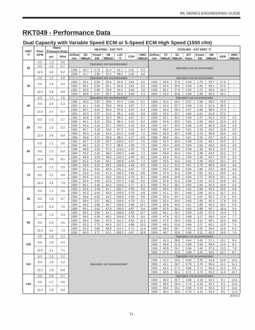
71
RK SERIES ENGINEERING GUIDE
RKT049 - Performance DataDual Capacity with Variable Speed ECM or 5-Speed ECM High Speed (1550 cfm)
EWT°F
Flow GPM
WaterPressure Drop HEATING - EAT 70°F COOLING - EAT 80/67 °F
psi ft/hd Airfl ow cfm
HC MBtu/h
Power kW
HE MBtu/h
LAT °F COP HWC
MBtu/hAirfl ow
cfmTC
MBtu/hSC
MBtu/hS/T
RatioPower
kWHR
MBtu/h EER HWC MBtu/h
20
6.0 1.3 3.0Operation not recommended
Operation not recommended9.0 2.5 5.7
12.0 4.0 9.21350 30.7 2.72 21.4 91.1 3.31 5.31550 31.7 2.80 22.2 89.0 3.32 4.8
30
6.0 1.2 2.9 Operation not recommended Operation not recommended
9.0 2.4 5.51350 35.1 2.84 25.3 94.0 3.61 5.6 1350 49.6 27.8 0.56 1.79 55.7 27.6 ---1550 36.1 2.94 26.1 91.6 3.61 5.2 1550 52.6 30.9 0.59 1.91 59.1 27.5 ---
12.0 3.9 8.91350 35.6 2.88 25.8 94.4 3.63 5.8 1350 50.1 27.8 0.55 1.71 56.0 29.4 ---1550 36.8 2.97 26.7 92.0 3.63 5.3 1550 53.0 30.8 0.58 1.83 59.3 29.1 ---
40
6.0 1.2 2.8 Operation not recommended Operation not recommended
9.0 2.3 5.31350 40.0 2.97 29.8 97.4 3.94 6.2 1350 51.5 29.4 0.57 1.98 58.2 25.9 ---1550 41.1 3.04 30.8 94.6 3.97 5.7 1550 54.4 32.7 0.60 2.10 61.6 25.9 ---
12.0 3.7 8.71350 40.7 3.01 30.4 97.9 3.97 6.4 1350 52.0 29.4 0.57 1.90 58.5 27.4 ---1550 42.0 3.07 31.5 95.1 4.01 5.8 1550 54.9 32.7 0.60 2.01 61.8 27.2 ---
50
6.0 1.2 2.71350 42.8 3.08 32.3 99.3 4.07 6.7 1350 52.1 30.2 0.58 2.37 60.2 22.0 3.01550 44.1 3.12 33.5 96.4 4.15 6.2 1550 54.8 33.5 0.61 2.50 63.4 22.0 3.2
9.0 2.2 5.21350 44.4 3.14 33.7 100.5 4.15 6.9 1350 52.7 30.6 0.58 2.22 60.3 23.8 2.81550 45.7 3.18 34.8 97.3 4.21 6.4 1550 55.5 34.0 0.61 2.33 63.5 23.8 3.0
12.0 3.6 8.41350 45.3 3.18 34.5 101.1 4.18 7.2 1350 53.3 30.7 0.58 2.13 60.6 25.0 2.61550 46.8 3.21 35.8 98.0 4.27 6.5 1550 56.0 34.1 0.61 2.25 63.7 24.9 2.9
60
6.0 1.1 2.61350 46.7 3.20 35.7 102.0 4.27 7.6 1350 51.5 30.5 0.59 2.51 60.1 20.5 3.71550 48.1 3.22 37.2 98.8 4.38 7.0 1550 54.0 33.8 0.63 2.63 63.0 20.6 3.9
9.0 2.2 5.01350 48.8 3.28 37.6 103.4 4.35 7.8 1350 52.3 30.9 0.59 2.38 60.4 22.0 3.41550 50.2 3.30 39.0 100.0 4.46 7.2 1550 54.9 34.3 0.62 2.48 63.4 22.2 3.7
12.0 3.5 8.11350 49.9 3.33 38.6 104.2 4.40 8.0 1350 52.9 31.0 0.59 2.30 60.7 23.0 3.21550 51.5 3.34 40.1 100.8 4.53 7.4 1550 55.5 34.5 0.62 2.40 63.6 23.1 3.5
70
6.0 1.1 2.51350 50.5 3.32 39.2 104.6 4.46 8.5 1350 51.2 31.0 0.61 2.75 60.6 18.6 4.61550 52.1 3.31 40.8 101.1 4.61 7.9 1550 53.5 34.5 0.64 2.85 63.2 18.8 4.9
9.0 2.1 4.91350 53.0 3.42 41.3 106.3 4.54 8.8 1350 52.3 31.4 0.60 2.62 61.2 20.0 4.31550 54.6 3.41 43.0 102.6 4.70 8.1 1550 54.6 34.8 0.64 2.72 63.9 20.1 4.6
12.0 3.4 7.91350 54.4 3.46 42.6 107.3 4.60 9.0 1350 52.8 31.6 0.60 2.54 61.5 20.8 4.01550 56.1 3.45 44.4 103.5 4.77 8.3 1550 55.2 35.1 0.64 2.64 64.3 20.9 4.4
80
6.0 1.1 2.51350 53.6 3.49 41.7 106.7 4.50 9.6 1350 49.0 30.3 0.62 2.98 59.2 16.5 5.81550 55.3 3.45 43.5 103.0 4.70 8.8 1550 51.1 33.7 0.66 3.06 61.5 16.7 6.2
9.0 2.0 4.71350 56.6 3.62 44.2 108.8 4.58 9.8 1350 50.3 30.7 0.61 2.87 60.1 17.6 5.41550 58.4 3.57 46.2 104.9 4.79 9.1 1550 52.4 34.0 0.65 2.95 62.4 17.8 5.9
12.0 3.3 7.61350 58.2 3.66 45.7 109.9 4.66 10.1 1350 50.8 30.9 0.61 2.80 60.4 18.2 5.01550 60.1 3.62 47.8 105.9 4.87 9.4 1550 52.9 34.3 0.65 2.88 62.7 18.4 5.6
90
6.0 1.0 2.41350 56.5 3.66 44.1 108.8 4.53 10.7 1350 46.1 29.1 0.63 3.20 57.0 14.4 7.31550 58.5 3.58 46.2 104.9 4.78 9.9 1550 47.8 32.3 0.68 3.27 59.0 14.6 7.7
9.0 2.0 4.51350 60.0 3.81 47.0 111.2 4.62 11.1 1350 47.5 29.4 0.62 3.11 58.1 15.3 6.81550 62.0 3.73 49.3 107.1 4.88 10.2 1550 49.3 32.6 0.66 3.17 60.1 15.5 7.4
12.0 3.2 7.31350 61.9 3.85 48.8 112.4 4.72 11.4 1350 48.0 29.7 0.62 3.05 58.4 15.8 6.31550 64.0 3.77 51.1 108.2 4.97 10.6 1550 49.7 33.0 0.66 3.11 60.3 16.0 7.0
100
6.0 1.0 2.3
Operation not recommended
Operation not recommended
9.0 1.9 4.41350 45.3 28.8 0.64 3.45 57.1 13.1 8.41550 46.8 31.9 0.68 3.50 58.8 13.4 9.2
12.0 3.1 7.11350 45.8 29.1 0.64 3.40 57.4 13.5 7.81550 47.3 32.3 0.68 3.45 59.0 13.7 8.7
110
6.0 1.0 2.2 Operation not recommended
9.0 1.8 4.21350 41.0 26.8 0.66 3.75 53.8 10.9 10.31550 42.1 29.7 0.70 3.78 55.0 11.1 11.2
12.0 2.9 6.81350 41.4 27.2 0.66 3.71 54.0 11.2 9.61550 42.5 30.1 0.71 3.74 55.3 11.4 10.7
120
6.0 0.9 2.1 Operation not recommended
9.0 1.7 4.01350 38.0 25.7 0.68 4.18 52.3 9.1 12.51550 38.9 28.4 0.73 4.18 53.2 9.3 13.5
12.0 2.8 6.51350 38.4 26.1 0.68 4.14 52.5 9.3 11.61550 39.3 28.9 0.74 4.14 53.4 9.5 12.9
3/16/12
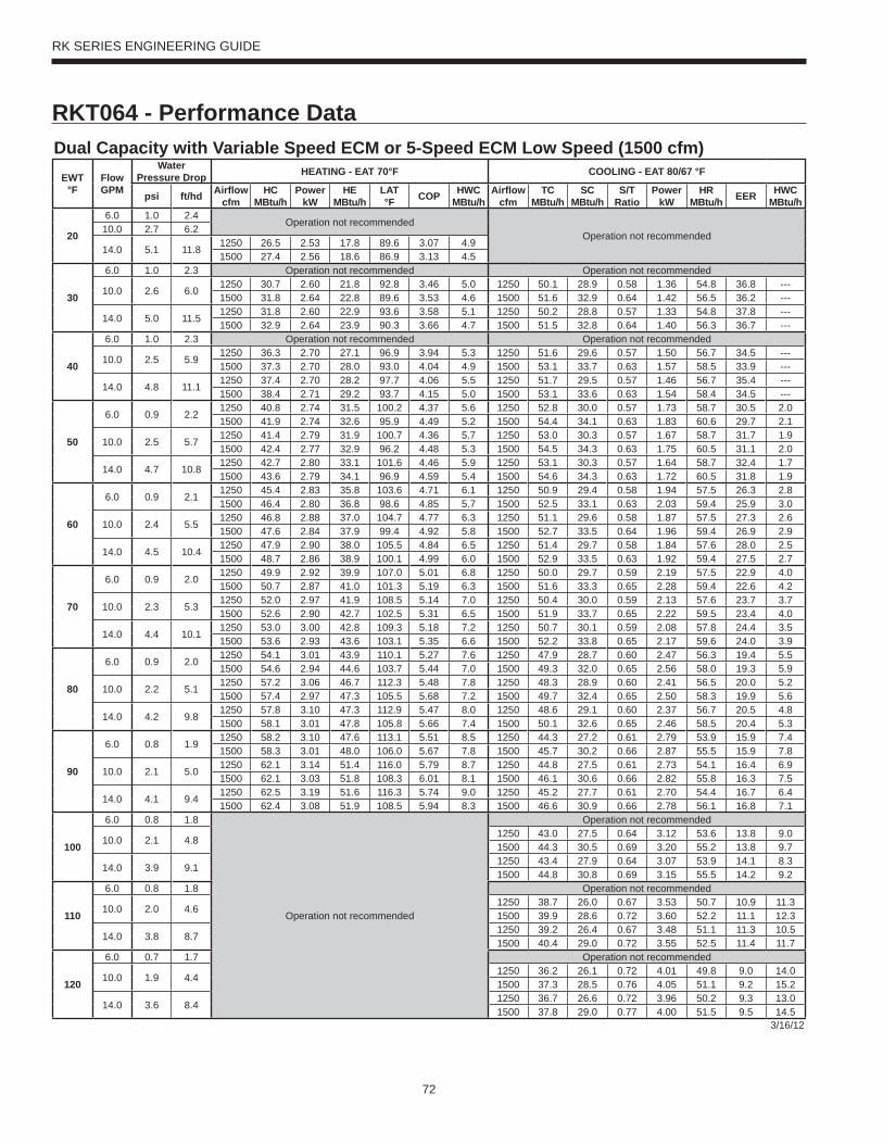
72
RK SERIES ENGINEERING GUIDE
RKT064 - Performance DataDual Capacity with Variable Speed ECM or 5-Speed ECM Low Speed (1500 cfm)
EWT°F
Flow GPM
WaterPressure Drop HEATING - EAT 70°F COOLING - EAT 80/67 °F
psi ft/hd Airfl ow cfm
HC MBtu/h
Power kW
HE MBtu/h
LAT °F COP HWC
MBtu/hAirfl ow
cfmTC
MBtu/hSC
MBtu/hS/T
RatioPower
kWHR
MBtu/h EER HWC MBtu/h
20
6.0 1.0 2.4Operation not recommended
Operation not recommended10.0 2.7 6.2
14.0 5.1 11.81250 26.5 2.53 17.8 89.6 3.07 4.91500 27.4 2.56 18.6 86.9 3.13 4.5
30
6.0 1.0 2.3 Operation not recommended Operation not recommended
10.0 2.6 6.01250 30.7 2.60 21.8 92.8 3.46 5.0 1250 50.1 28.9 0.58 1.36 54.8 36.8 ---1500 31.8 2.64 22.8 89.6 3.53 4.6 1500 51.6 32.9 0.64 1.42 56.5 36.2 ---
14.0 5.0 11.51250 31.8 2.60 22.9 93.6 3.58 5.1 1250 50.2 28.8 0.57 1.33 54.8 37.8 ---1500 32.9 2.64 23.9 90.3 3.66 4.7 1500 51.5 32.8 0.64 1.40 56.3 36.7 ---
40
6.0 1.0 2.3 Operation not recommended Operation not recommended
10.0 2.5 5.91250 36.3 2.70 27.1 96.9 3.94 5.3 1250 51.6 29.6 0.57 1.50 56.7 34.5 ---1500 37.3 2.70 28.0 93.0 4.04 4.9 1500 53.1 33.7 0.63 1.57 58.5 33.9 ---
14.0 4.8 11.11250 37.4 2.70 28.2 97.7 4.06 5.5 1250 51.7 29.5 0.57 1.46 56.7 35.4 ---1500 38.4 2.71 29.2 93.7 4.15 5.0 1500 53.1 33.6 0.63 1.54 58.4 34.5 ---
50
6.0 0.9 2.21250 40.8 2.74 31.5 100.2 4.37 5.6 1250 52.8 30.0 0.57 1.73 58.7 30.5 2.01500 41.9 2.74 32.6 95.9 4.49 5.2 1500 54.4 34.1 0.63 1.83 60.6 29.7 2.1
10.0 2.5 5.71250 41.4 2.79 31.9 100.7 4.36 5.7 1250 53.0 30.3 0.57 1.67 58.7 31.7 1.91500 42.4 2.77 32.9 96.2 4.48 5.3 1500 54.5 34.3 0.63 1.75 60.5 31.1 2.0
14.0 4.7 10.81250 42.7 2.80 33.1 101.6 4.46 5.9 1250 53.1 30.3 0.57 1.64 58.7 32.4 1.71500 43.6 2.79 34.1 96.9 4.59 5.4 1500 54.6 34.3 0.63 1.72 60.5 31.8 1.9
60
6.0 0.9 2.11250 45.4 2.83 35.8 103.6 4.71 6.1 1250 50.9 29.4 0.58 1.94 57.5 26.3 2.81500 46.4 2.80 36.8 98.6 4.85 5.7 1500 52.5 33.1 0.63 2.03 59.4 25.9 3.0
10.0 2.4 5.51250 46.8 2.88 37.0 104.7 4.77 6.3 1250 51.1 29.6 0.58 1.87 57.5 27.3 2.61500 47.6 2.84 37.9 99.4 4.92 5.8 1500 52.7 33.5 0.64 1.96 59.4 26.9 2.9
14.0 4.5 10.41250 47.9 2.90 38.0 105.5 4.84 6.5 1250 51.4 29.7 0.58 1.84 57.6 28.0 2.51500 48.7 2.86 38.9 100.1 4.99 6.0 1500 52.9 33.5 0.63 1.92 59.4 27.5 2.7
70
6.0 0.9 2.01250 49.9 2.92 39.9 107.0 5.01 6.8 1250 50.0 29.7 0.59 2.19 57.5 22.9 4.01500 50.7 2.87 41.0 101.3 5.19 6.3 1500 51.6 33.3 0.65 2.28 59.4 22.6 4.2
10.0 2.3 5.31250 52.0 2.97 41.9 108.5 5.14 7.0 1250 50.4 30.0 0.59 2.13 57.6 23.7 3.71500 52.6 2.90 42.7 102.5 5.31 6.5 1500 51.9 33.7 0.65 2.22 59.5 23.4 4.0
14.0 4.4 10.11250 53.0 3.00 42.8 109.3 5.18 7.2 1250 50.7 30.1 0.59 2.08 57.8 24.4 3.51500 53.6 2.93 43.6 103.1 5.35 6.6 1500 52.2 33.8 0.65 2.17 59.6 24.0 3.9
80
6.0 0.9 2.01250 54.1 3.01 43.9 110.1 5.27 7.6 1250 47.9 28.7 0.60 2.47 56.3 19.4 5.51500 54.6 2.94 44.6 103.7 5.44 7.0 1500 49.3 32.0 0.65 2.56 58.0 19.3 5.9
10.0 2.2 5.11250 57.2 3.06 46.7 112.3 5.48 7.8 1250 48.3 28.9 0.60 2.41 56.5 20.0 5.21500 57.4 2.97 47.3 105.5 5.68 7.2 1500 49.7 32.4 0.65 2.50 58.3 19.9 5.6
14.0 4.2 9.81250 57.8 3.10 47.3 112.9 5.47 8.0 1250 48.6 29.1 0.60 2.37 56.7 20.5 4.81500 58.1 3.01 47.8 105.8 5.66 7.4 1500 50.1 32.6 0.65 2.46 58.5 20.4 5.3
90
6.0 0.8 1.91250 58.2 3.10 47.6 113.1 5.51 8.5 1250 44.3 27.2 0.61 2.79 53.9 15.9 7.41500 58.3 3.01 48.0 106.0 5.67 7.8 1500 45.7 30.2 0.66 2.87 55.5 15.9 7.8
10.0 2.1 5.01250 62.1 3.14 51.4 116.0 5.79 8.7 1250 44.8 27.5 0.61 2.73 54.1 16.4 6.91500 62.1 3.03 51.8 108.3 6.01 8.1 1500 46.1 30.6 0.66 2.82 55.8 16.3 7.5
14.0 4.1 9.41250 62.5 3.19 51.6 116.3 5.74 9.0 1250 45.2 27.7 0.61 2.70 54.4 16.7 6.41500 62.4 3.08 51.9 108.5 5.94 8.3 1500 46.6 30.9 0.66 2.78 56.1 16.8 7.1
100
6.0 0.8 1.8
Operation not recommended
Operation not recommended
10.0 2.1 4.81250 43.0 27.5 0.64 3.12 53.6 13.8 9.01500 44.3 30.5 0.69 3.20 55.2 13.8 9.7
14.0 3.9 9.11250 43.4 27.9 0.64 3.07 53.9 14.1 8.31500 44.8 30.8 0.69 3.15 55.5 14.2 9.2
110
6.0 0.8 1.8 Operation not recommended
10.0 2.0 4.61250 38.7 26.0 0.67 3.53 50.7 10.9 11.31500 39.9 28.6 0.72 3.60 52.2 11.1 12.3
14.0 3.8 8.71250 39.2 26.4 0.67 3.48 51.1 11.3 10.51500 40.4 29.0 0.72 3.55 52.5 11.4 11.7
120
6.0 0.7 1.7 Operation not recommended
10.0 1.9 4.41250 36.2 26.1 0.72 4.01 49.8 9.0 14.01500 37.3 28.5 0.76 4.05 51.1 9.2 15.2
14.0 3.6 8.41250 36.7 26.6 0.72 3.96 50.2 9.3 13.01500 37.8 29.0 0.77 4.00 51.5 9.5 14.5
3/16/12

73
RK SERIES ENGINEERING GUIDE
RKT064 - Performance DataDual Capacity with Variable Speed ECM or 5-Speed ECM High Speed (1800 cfm)
EWT°F
Flow GPM
WaterPressure Drop HEATING - EAT 70°F COOLING - EAT 80/67 °F
psi ft/hd Airfl ow cfm
HC MBtu/h
Power kW
HE MBtu/h
LAT °F COP HWC
MBtu/hAirfl ow
cfmTC
MBtu/hSC
MBtu/hS/T
RatioPower
kWHR
MBtu/h EER HWC MBtu/h
20
8.0 1.8 4.2Operation not recommended
Operation not recommended12.0 3.8 8.8
16.0 6.5 15.11500 39.7 3.44 28.0 94.5 3.38 6.21800 40.7 3.60 28.4 90.9 3.31 5.6
30
8.0 1.8 4.1 Operation not recommended Operation not recommended
12.0 3.7 8.61500 45.8 3.46 34.0 98.3 3.88 6.5 1500 65.1 40.8 0.63 2.23 72.7 29.1 ---1800 47.1 3.68 34.5 94.2 3.75 6.0 1800 65.7 44.4 0.68 2.37 73.7 27.7 ---
16.0 6.4 14.71500 46.4 3.55 34.3 98.7 3.84 6.7 1500 65.7 41.2 0.63 2.19 73.2 30.0 ---1800 47.6 3.71 34.9 94.5 3.76 6.1 1800 66.2 44.8 0.68 2.33 74.1 28.4 ---
40
8.0 1.7 4.0 Operation not recommended Operation not recommended
12.0 3.6 8.31500 52.7 3.69 40.1 102.5 4.19 7.2 1500 67.6 41.9 0.62 2.56 76.4 26.4 ---1800 53.9 3.84 40.8 97.7 4.11 6.6 1800 68.6 45.6 0.66 2.72 77.9 25.2 ---
16.0 6.2 14.21500 53.5 3.75 40.7 103.0 4.18 7.4 1500 68.3 42.3 0.62 2.52 76.9 27.1 ---1800 54.7 3.88 41.5 98.2 4.13 6.7 1800 69.2 46.0 0.66 2.68 78.4 25.9 ---
50
8.0 1.7 3.81500 56.2 3.84 43.1 104.7 4.29 7.8 1500 68.7 42.2 0.61 3.00 78.9 22.9 4.01800 57.4 3.96 43.9 99.5 4.25 7.2 1800 70.1 45.9 0.65 3.19 81.0 22.0 4.2
12.0 3.5 8.11500 59.5 3.91 46.1 106.7 4.45 8.0 1500 69.4 42.6 0.61 2.94 79.4 23.6 3.71800 60.7 4.01 47.0 101.2 4.43 7.4 1800 70.8 46.4 0.65 3.12 81.5 22.7 4.0
16.0 6.0 13.81500 60.4 3.96 46.9 107.3 4.48 8.2 1500 70.1 43.1 0.61 2.89 80.0 24.3 3.41800 61.8 4.05 47.9 101.8 4.47 7.5 1800 71.5 46.8 0.65 3.07 82.0 23.3 3.8
60
8.0 1.6 3.71500 63.1 4.10 49.1 108.9 4.51 8.7 1500 67.1 41.8 0.62 3.23 78.2 20.8 4.81800 64.4 4.17 50.2 103.1 4.53 8.0 1800 68.8 45.5 0.66 3.44 80.6 20.0 5.1
12.0 3.4 7.81500 65.9 4.17 51.7 110.7 4.64 9.0 1500 67.8 42.2 0.62 3.17 78.6 21.4 4.51800 67.4 4.22 53.0 104.7 4.68 8.3 1800 69.6 45.9 0.66 3.37 81.1 20.7 4.9
16.0 5.8 13.41500 67.4 4.22 53.0 111.6 4.68 9.2 1500 68.5 42.7 0.62 3.12 79.1 22.0 4.21800 68.9 4.26 54.3 105.4 4.74 8.5 1800 70.2 46.4 0.66 3.31 81.5 21.2 4.6
70
8.0 1.6 3.61500 70.0 4.39 55.0 113.2 4.67 9.8 1500 67.7 42.2 0.62 3.60 80.0 18.8 6.11800 71.5 4.41 56.4 106.8 4.75 9.0 1800 69.8 45.9 0.66 3.83 82.9 18.2 6.4
12.0 3.3 7.51500 72.5 4.46 57.3 114.8 4.77 10.1 1500 68.4 42.6 0.62 3.53 80.4 19.4 5.71800 74.2 4.47 58.9 108.2 4.87 9.3 1800 70.6 46.3 0.66 3.75 83.4 18.8 6.1
16.0 5.6 12.91500 74.4 4.51 59.0 115.9 4.84 10.4 1500 69.0 43.0 0.62 3.46 80.9 19.9 5.31800 76.1 4.51 60.7 109.2 4.95 9.6 1800 71.2 46.8 0.66 3.69 83.8 19.3 5.8
80
8.0 1.5 3.51500 76.9 4.68 60.9 117.4 4.82 11.0 1500 63.8 40.8 0.64 3.90 77.1 16.3 7.71800 78.6 4.65 62.8 110.5 4.95 10.2 1800 66.1 44.3 0.67 4.16 80.3 15.9 8.1
12.0 3.2 7.31500 78.7 4.74 62.5 118.6 4.87 11.3 1500 64.4 41.1 0.64 3.83 77.5 16.8 7.11800 80.6 4.69 64.6 111.4 5.04 10.5 1800 66.8 44.7 0.67 4.07 80.7 16.4 7.7
16.0 5.4 12.51500 81.1 4.79 64.7 120.0 4.96 11.7 1500 65.1 41.6 0.64 3.76 77.9 17.3 6.61800 83.1 4.74 66.9 112.7 5.14 10.8 1800 67.5 45.2 0.67 4.00 81.1 16.9 7.4
90
8.0 1.4 3.31500 83.8 5.00 66.8 121.7 4.92 12.4 1500 58.7 39.3 0.67 4.18 72.9 14.0 9.61800 85.8 4.92 69.0 114.2 5.11 11.4 1800 61.3 42.7 0.70 4.45 76.5 13.8 10.2
12.0 3.0 7.01500 84.9 5.05 67.7 122.4 4.93 12.7 1500 59.3 39.6 0.67 4.10 73.3 14.5 9.01800 87.1 4.95 70.2 114.8 5.16 11.8 1800 61.8 43.1 0.70 4.36 76.7 14.2 9.7
16.0 5.2 12.01500 87.9 5.12 70.4 124.2 5.03 13.1 1500 59.9 40.1 0.67 4.03 73.7 14.9 8.31800 90.2 5.00 73.1 116.4 5.29 12.2 1800 62.5 43.5 0.70 4.29 77.2 14.6 9.2
100
8.0 1.4 3.2
Operation not recommended
Operation not recommended
12.0 2.9 6.81500 57.7 38.6 0.67 4.53 73.1 12.7 11.11800 60.4 42.0 0.70 4.83 76.9 12.5 12.1
16.0 5.0 11.61500 58.2 39.1 0.67 4.45 73.4 13.1 10.31800 61.0 42.4 0.70 4.75 77.2 12.9 11.5
110
8.0 1.3 3.1 Operation not recommended
12.0 2.8 6.51500 51.0 35.3 0.69 4.84 67.5 10.5 13.61800 53.7 38.3 0.71 5.17 71.4 10.4 14.8
16.0 4.8 11.21500 51.5 35.7 0.69 4.76 67.7 10.8 12.71800 54.2 38.8 0.72 5.08 71.5 10.7 14.1
120
8.0 1.3 3.0 Operation not recommended
12.0 2.7 6.31500 49.6 35.9 0.72 5.34 67.9 9.3 16.51800 52.5 39.0 0.74 5.70 72.0 9.2 17.9
16.0 4.6 10.71500 50.1 36.3 0.73 5.25 68.0 9.5 15.31800 53.0 39.5 0.75 5.61 72.1 9.4 17.0
3/16/12
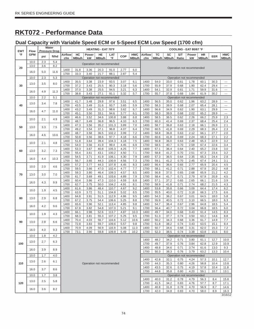
74
RK SERIES ENGINEERING GUIDE
RKT072 - Performance DataDual Capacity with Variable Speed ECM or 5-Speed ECM Low Speed (1700 cfm)
EWT°F
Flow GPM
WaterPressure Drop HEATING - EAT 70°F COOLING - EAT 80/67 °F
psi ft/hd Airfl ow cfm
HC MBtu/h
Power kW
HE MBtu/h
LAT °F COP HWC
MBtu/hAirfl ow
cfmTC
MBtu/hSC
MBtu/hS/T
RatioPower
kWHR
MBtu/h EER HWC MBtu/h
20
10.0 2.3 5.4Operation not recommended
Operation not recommended13.0 3.6 8.2
16.0 5.0 11.61400 31.8 3.36 20.3 91.0 2.77 6.01700 33.3 3.40 21.7 88.1 2.87 5.4
30
10.0 2.3 5.3 Operation not recommended Operation not recommended
13.0 3.5 8.01400 35.5 3.38 23.9 93.5 3.07 6.1 1400 54.0 33.0 0.61 1.78 60.1 30.3 ---1700 37.2 3.43 25.5 90.3 3.18 5.6 1700 55.9 37.9 0.68 1.90 62.4 29.4 ---
16.0 4.9 11.31400 37.0 3.38 25.5 94.5 3.21 6.3 1400 54.1 32.9 0.61 1.71 59.9 31.6 ---1700 38.8 3.43 27.1 91.1 3.32 5.7 1700 55.7 37.8 0.68 1.84 61.9 30.2 ---
40
10.0 2.2 5.1 Operation not recommended Operation not recommended
13.0 3.4 7.81400 41.7 3.48 29.8 97.6 3.51 6.5 1400 56.5 35.0 0.62 1.96 63.2 28.9 ---1700 43.5 3.49 31.6 93.7 3.65 5.9 1700 58.3 39.9 0.68 2.07 65.4 28.1 ---
16.0 4.7 11.01400 43.2 3.49 31.3 98.6 3.62 6.7 1400 56.6 34.9 0.62 1.90 63.1 29.9 ---1700 45.1 3.50 33.1 94.6 3.77 6.1 1700 58.3 39.9 0.68 2.02 65.2 28.9 ---
50
10.0 2.1 4.91400 46.6 3.52 34.6 100.8 3.88 6.8 1400 58.5 36.5 0.62 2.26 66.2 25.9 2.31700 48.7 3.49 36.8 96.5 4.10 6.3 1700 60.3 41.4 0.69 2.37 68.4 25.4 2.4
13.0 3.3 7.51400 47.3 3.56 35.2 101.3 3.89 7.0 1400 58.7 36.8 0.63 2.18 66.1 26.9 2.11700 49.2 3.54 37.1 96.8 4.07 6.4 1700 60.5 41.8 0.69 2.29 68.3 26.4 2.3
16.0 4.6 10.61400 48.7 3.58 36.5 102.2 3.99 7.2 1400 58.8 36.8 0.63 2.12 66.1 27.7 2.01700 50.8 3.56 38.6 97.7 4.18 6.6 1700 60.6 41.8 0.69 2.24 68.3 27.1 2.2
60
10.0 2.1 4.81400 51.8 3.64 39.4 104.3 4.18 7.5 1400 56.8 36.0 0.63 2.48 65.3 22.9 3.21700 54.0 3.56 41.9 99.4 4.45 6.9 1700 58.5 40.7 0.70 2.59 67.4 22.6 3.4
13.0 3.2 7.31400 53.3 3.67 40.8 105.3 4.25 7.7 1400 57.1 36.4 0.64 2.40 65.2 23.8 3.01700 55.4 3.61 43.1 100.2 4.50 7.1 1700 58.8 41.2 0.70 2.51 67.3 23.4 3.2
16.0 4.4 10.31400 54.5 3.71 41.9 106.1 4.30 7.9 1400 57.3 36.5 0.64 2.35 65.3 24.4 2.81700 56.7 3.65 44.3 100.9 4.56 7.3 1700 59.1 41.2 0.70 2.45 67.4 24.1 3.1
70
10.0 2.0 4.61400 57.2 3.77 44.3 107.8 4.45 8.3 1400 56.4 36.6 0.65 2.77 65.9 20.4 4.51700 59.5 3.66 47.0 102.4 4.77 7.7 1700 58.1 41.2 0.71 2.88 67.9 20.2 4.8
13.0 3.0 7.01400 59.3 3.80 46.4 109.3 4.57 8.5 1400 56.8 37.0 0.65 2.68 65.9 21.2 4.21700 61.7 3.69 49.1 103.6 4.89 7.9 1700 58.4 41.7 0.71 2.79 67.9 20.9 4.5
16.0 4.3 9.91400 60.4 3.86 47.3 110.0 4.59 8.8 1400 57.1 37.2 0.65 2.65 66.1 21.6 3.91700 62.7 3.75 50.0 104.2 4.91 8.1 1700 58.9 41.8 0.71 2.74 68.2 21.5 4.3
80
10.0 1.9 4.51400 61.6 3.86 48.4 110.7 4.67 9.2 1400 53.8 35.8 0.66 3.09 64.4 17.4 6.21700 63.9 3.72 51.1 104.8 5.02 8.5 1700 55.5 40.0 0.72 3.18 66.3 17.5 6.6
13.0 2.9 6.81400 64.8 3.91 51.5 112.9 4.86 9.5 1400 54.3 36.2 0.67 3.01 64.5 18.0 5.81700 67.2 3.75 54.4 106.6 5.25 8.8 1700 55.9 40.5 0.72 3.10 66.5 18.0 6.3
16.0 4.2 9.61400 65.6 3.96 52.1 113.4 4.85 9.8 1400 54.7 36.4 0.67 2.96 64.8 18.5 5.41700 67.8 3.82 54.8 107.0 5.21 9.1 1700 56.4 40.7 0.72 3.04 66.8 18.5 6.0
90
10.0 1.9 4.31400 66.1 3.98 52.6 113.7 4.87 10.3 1400 49.7 34.0 0.68 3.43 61.4 14.5 8.31700 68.3 3.81 55.3 107.2 5.25 9.5 1700 51.3 37.7 0.74 3.50 63.2 14.6 8.8
13.0 2.8 6.61400 70.4 4.03 56.7 116.6 5.12 10.6 1400 50.2 34.3 0.68 3.36 61.7 14.9 7.71700 72.8 3.83 59.7 109.6 5.57 9.8 1700 51.8 38.2 0.74 3.43 63.5 15.1 8.4
16.0 4.0 9.31400 70.9 4.09 56.9 116.9 5.08 11.0 1400 50.7 34.6 0.68 3.31 62.0 15.3 7.21700 73.1 3.90 59.8 109.8 5.49 10.2 1700 52.3 38.5 0.74 3.38 63.8 15.5 8.0
100
10.0 1.8 4.2
Operation not recommended
Operation not recommended
13.0 2.7 6.31400 48.2 34.2 0.71 3.80 61.1 12.7 10.01700 49.7 37.9 0.76 3.84 62.8 12.9 10.9
16.0 3.9 8.91400 48.8 34.6 0.71 3.74 61.6 13.0 9.31700 50.3 38.3 0.76 3.79 63.2 13.3 10.4
110
10.0 1.7 4.0 Operation not recommended
13.0 2.6 6.11400 42.8 32.1 0.75 4.24 57.3 10.1 12.71700 44.3 35.3 0.80 4.26 58.8 10.4 13.8
16.0 3.7 8.61400 43.5 32.6 0.75 4.19 57.8 10.4 11.81700 44.8 35.8 0.80 4.20 59.1 10.7 13.1
120
10.0 1.7 3.8 Operation not recommended
13.0 2.5 5.81400 40.0 31.2 0.78 4.79 56.3 8.4 15.81700 41.5 34.2 0.83 4.76 57.7 8.7 17.1
16.0 3.6 8.21400 40.8 31.8 0.78 4.70 56.9 8.7 14.61700 42.0 34.8 0.83 4.70 58.0 8.9 16.3
3/16/12

75
RK SERIES ENGINEERING GUIDE
RKT072 - Performance DataDual Capacity with Variable Speed ECM or 5-Speed ECM High Speed (2200 cfm)
EWT°F
Flow GPM
WaterPressure Drop HEATING - EAT 70°F COOLING - EAT 80/67 °F
psi ft/hd Airfl ow cfm
HC MBtu/h
Power kW
HE MBtu/h
LAT °F COP HWC
MBtu/hAirfl ow
cfmTC
MBtu/hSC
MBtu/hS/T
RatioPower
kWHR
MBtu/h EER HWC MBtu/h
20
12.0 3.3 7.6Operation not recommended
Operation not recommended15.0 4.6 10.7
18.0 6.2 14.31850 45.4 4.17 31.2 92.7 3.19 7.92200 47.1 4.44 31.9 89.8 3.11 7.1
30
12.0 3.2 7.4 Operation not recommended Operation not recommended
15.0 4.5 10.41850 52.6 4.33 37.8 96.3 3.56 8.3 1850 70.5 43.0 0.61 2.51 79.1 28.1 ---2200 54.5 4.60 38.7 92.9 3.47 7.6 2200 71.8 46.8 0.65 2.66 80.9 27.0 ---
18.0 6.0 13.91850 53.0 4.37 38.1 96.5 3.56 8.6 1850 71.2 43.8 0.61 2.46 79.6 28.9 ---2200 55.0 4.65 39.1 93.1 3.47 7.8 2200 72.5 47.1 0.65 2.62 81.5 27.7 ---
40
12.0 3.1 7.1 Operation not recommended Operation not recommended
15.0 4.4 10.11850 61.0 4.60 45.3 100.5 3.89 9.2 1850 73.3 45.8 0.62 3.03 83.6 24.2 ---2200 63.1 4.81 46.7 96.5 3.84 8.4 2200 74.7 49.8 0.67 3.21 85.7 23.3 ---
18.0 5.8 13.51850 61.9 4.65 46.0 101.0 3.90 9.5 1850 74.1 46.6 0.63 2.97 84.2 24.9 ---2200 64.0 4.86 47.4 96.9 3.86 8.6 2200 75.5 50.2 0.66 3.16 86.3 23.9 ---
50
12.0 3.0 6.91850 64.9 4.79 48.6 102.5 3.97 9.9 1850 74.7 47.6 0.64 3.68 87.2 20.3 4.32200 67.1 4.96 50.2 98.2 3.97 9.2 2200 76.2 51.8 0.68 3.90 89.6 19.5 4.6
15.0 4.2 9.81850 68.6 4.88 51.9 104.3 4.12 10.3 1850 75.4 48.1 0.64 3.60 87.7 21.0 4.02200 70.9 5.04 53.7 99.8 4.12 9.4 2200 76.9 52.4 0.68 3.83 90.0 20.1 4.4
18.0 5.7 13.11850 69.8 4.94 53.0 104.9 4.14 10.6 1850 76.2 49.1 0.64 3.54 88.3 21.5 3.72200 72.1 5.09 54.7 100.3 4.15 9.7 2200 77.7 52.8 0.68 3.77 90.6 20.6 4.2
60
12.0 2.9 6.71850 73.0 5.10 55.6 106.5 4.19 11.1 1850 73.3 47.7 0.65 3.91 86.7 18.8 5.32200 75.4 5.20 57.6 101.7 4.24 10.3 2200 74.9 51.6 0.69 4.15 89.0 18.0 5.6
15.0 4.1 9.51850 76.2 5.19 58.5 108.2 4.30 11.5 1850 74.1 48.2 0.65 3.82 87.1 19.4 4.92200 78.7 5.27 60.7 103.1 4.37 10.6 2200 75.6 52.1 0.69 4.06 89.4 18.6 5.3
18.0 5.5 12.71850 77.9 5.25 60.0 109.0 4.35 11.8 1850 74.9 48.9 0.65 3.76 87.7 19.9 4.62200 80.5 5.33 62.3 103.9 4.43 10.9 2200 76.4 52.7 0.69 4.00 90.0 19.1 5.1
70
12.0 2.8 6.51850 81.2 5.42 62.7 110.6 4.39 12.5 1850 73.3 48.7 0.66 4.34 88.1 16.9 6.62200 83.7 5.46 65.1 105.2 4.49 11.6 2200 74.8 52.3 0.70 4.62 90.6 16.2 7.0
15.0 4.0 9.11850 84.0 5.51 65.2 112.0 4.47 12.9 1850 74.0 49.2 0.66 4.26 88.5 17.4 6.22200 86.7 5.52 67.8 106.5 4.60 11.9 2200 75.5 52.8 0.70 4.52 91.0 16.7 6.7
18.0 5.3 12.21850 86.2 5.57 67.2 113.1 4.53 13.3 1850 74.8 49.7 0.66 4.18 89.1 17.9 5.72200 89.0 5.57 70.0 107.5 4.68 12.3 2200 76.4 53.4 0.70 4.45 91.5 17.1 6.4
80
12.0 2.7 6.31850 88.3 5.78 68.6 114.2 4.48 14.1 1850 70.1 47.4 0.68 4.67 86.0 15.0 8.42200 91.2 5.74 71.6 108.4 4.66 13.0 2200 71.6 51.2 0.72 4.97 88.5 14.4 8.9
15.0 3.8 8.81850 90.4 5.86 70.4 115.3 4.52 14.5 1850 70.8 47.8 0.68 4.57 86.4 15.5 7.82200 93.3 5.78 73.6 109.3 4.73 13.4 2200 72.2 51.6 0.71 4.86 88.8 14.9 8.4
18.0 5.1 11.81850 93.2 5.94 72.9 116.6 4.60 15.0 1850 71.6 48.5 0.68 4.49 86.9 15.9 7.22200 96.3 5.84 76.3 110.5 4.83 13.8 2200 73.0 52.2 0.71 4.79 89.4 15.3 8.0
90
12.0 2.6 6.01850 95.6 6.15 74.6 117.9 4.56 15.8 1850 65.5 45.0 0.69 4.88 82.2 13.4 10.52200 98.8 6.03 78.2 111.6 4.80 14.7 2200 66.9 48.9 0.73 5.19 84.6 12.9 11.1
15.0 3.7 8.51850 97.0 6.22 75.7 118.5 4.57 16.3 1850 66.2 45.4 0.69 4.78 82.5 13.9 9.82200 100.1 6.06 79.4 112.1 4.84 15.1 2200 67.5 49.3 0.73 5.09 84.9 13.3 10.6
18.0 4.9 11.41850 100.3 6.30 78.8 120.2 4.66 16.8 1850 66.9 46.3 0.69 4.70 82.9 14.2 9.12200 103.6 6.12 82.7 113.6 4.96 15.6 2200 68.3 49.8 0.73 5.00 85.3 13.6 10.1
100
12.0 2.5 5.8
Operation not recommended
Operation not recommended
15.0 3.6 8.21850 63.4 44.7 0.71 5.27 81.4 12.0 12.22200 64.7 48.4 0.75 5.61 83.9 11.5 13.2
18.0 4.8 11.01850 64.1 45.4 0.71 5.18 81.8 12.4 11.32200 65.5 48.9 0.75 5.51 84.3 11.9 12.5
110
12.0 2.4 5.6 Operation not recommended
15.0 3.4 7.91850 56.6 41.4 0.73 5.51 75.4 10.3 14.92200 57.8 44.6 0.77 5.86 77.8 9.9 16.1
18.0 4.6 10.61850 57.3 41.9 0.73 5.41 75.7 10.6 13.82200 58.4 45.0 0.77 5.76 78.1 10.2 15.3
120
12.0 2.3 5.4 Operation not recommended
15.0 3.3 7.61850 53.6 40.2 0.75 6.04 74.3 8.9 18.02200 54.7 43.4 0.79 6.43 76.7 8.5 19.5
18.0 4.4 10.21850 54.2 40.7 0.75 5.94 74.5 9.1 16.72200 55.3 43.7 0.79 6.31 76.9 8.8 18.5
3/16/12
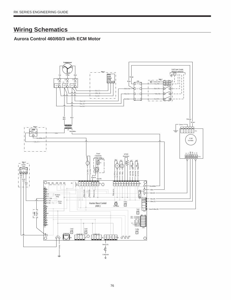
76
RK SERIES ENGINEERING GUIDE
Wiring SchematicsAurora Control 460/60/3 with ECM Motor
Transfo rmer
Blue460V
Black
YellowC
Y-OUTY
PGM
Yellow (91)
Black/White (92)
Black/White
Yellow
Black/White24V
ECM2 Fan Mo tor
P12
P112 3 4 51
1 312 15 10
PWM
C1 C2R G
16
CFM
Green
Violet (42)
Blue (24)Yellow (25)
Green/Yellow (28)
Brown
Orange
Red (51)
Green (50)
White (52)
Note 2Red (53)
Compressor
T1
T2
T3
L2L3
CCT2T3
L1
T1
DisconnectNeutralGround
L1 L1
L2 L2
L3 L3
Green (93)
YellowRed Black
L1 L2 L3
Phase Guard Monitor (PGM)
Black (7)White (8)Red (9)
Unit Power Supply460/60/3 w/Neutral
G
N
L1
L2
L3
PB3
Black (95)
Yellow (96)
Red (97)
Gray (94)Brown
Orange
Red (56)
Blue (55)
Black (54)
Red (56)Blue (55)Black (54)
CC
470
470Resistor
Violet (14)Black (15)
Orange (01)Orange (02)
Condensate
Brown (23)Green
RV
HPLP
T
FDRV
Blue (07)
Blue ( 08)Black (09)Black (10)
YellowYellow
UltraTech
Dual Capacity
Units Only
RCP
CS
Blue(16)Blue(18)
CFM
P13
P4
SW1
P5JW2
P9
LO
O/B
Y2WDH
P8 P7
RS485 NET RS485 NET
P6
RS485 EXP
P3
SW2
On
Future Use L Output Type
CC – Dual/SingleAcc – Dip 5Acc – Dip 4
RV – B/OFP2 – 15°F/30°FFP1 – 15°F/30°F
Com1LED5
Com2LED5
Test Mode
F1-3A
P1
C
PWM
12345678
ALMALGACC COMACC NOACC NC
RC
GY1
EH2CEH1CCOC R - +C R - +
Off
Faul tLED1
R
StatusLED3
ConfigLED2
CC2 CC F C R F FG CC CCGCC2HI
CC2LO
CC2G REVREVFP1 FP1 FP2 FP2 LPS LPSHPSHPS
Aurora Base Control(ABC)
K1-RV Relay
K2-CC Relay
K3-CC2 Relay
K4- Fan RelayK5-Alarm Relay
K6-Acc Relay
F
R
C
CCGY1C
R
ESLS
P2EH1
YG G
G
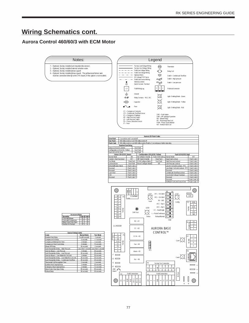
77
RK SERIES ENGINEERING GUIDE
Wiring Schematics cont.Aurora Control 460/60/3 with ECM Motor
Page 1
1 – Optional, factory installed unit mounted disconnect.2 – Optional, factory installed internal isolation valve.3 – Optional, factory installed phase guard4 – Optional, factory installed phase guard. The yellow transformer wire shall be connected directly to the CPU board, if this option is not installed.
Notes:
Slow FlashFast FlashFlash Code
Status LED (LED1, Green)Configuration LED (LED2, Yellow)Faul t LED (LED3, Red)
Sta tus LED (LED1, Green)Normal ModeControl is Non-FunctionalTest ModeLockout ActiveDehumidification ModeReservedReservedLoad ShedESD
1 second on and 1 second off
Random Start DelayFast Flash
OFFON
Slow FlashFast Flash
Flash Code 2Flash Code 3
Flash Code 6
Flash Code 4Flash Code 5
Aurora LED Flash Codes
100 milliseconds on and 100 milliseconds off100 milliseconds on and 400 milliseconds off with a 2 second pause before repeating
Reserved Flash Code 7
Configuration LED (LED2, Yellow) Fault LED (LED3, Red)
Fast FlashFast Flash
No Software Overide Flash ECM SettingDIP Switch Overide Slow Flash
Normal ModeInput Fault LockoutHigh Pressure LockoutLow Pressure Lockout
Low Water Coil Limi t Lockout - FP1Low Air Coil Limi t Lockout - FP2
ReservedCondensate Overflow LockoutOver/Under Voltage ShutdownReservedReservedAir/Water Coil Limit Sensor Error
Flash Code 1OFF
Flash Code 2Flash Code 3Flash Code 4Flash Code 5
Flash Code 8
Flash Code 6Flash Code 7
Flash Code 9Flash Code 10Flash Code 11
ECM Configu re Mode Fast FlashReset Configure Mode Off
Accessory Relay
Cycle with BlowerCycle with CompressorWater Valve Slow OpenOutdoor Air Damper
SW2-4 SW2-5On OnOff OffOn OffOff On
Operation
Event Normal Mode Test ModeRandom Start DelayCompressor On DelayCompressor Minimum On TimeCompressor Short Cycle DelayBlower Off DelayFaul t Recogn ition Delay – High PressureStart-Up Bypass – Low PressureFaul t Recogn ition Delay – Low PressureStart-Up Bypass – Low Water/Air Coil LimitFaul t Recogn ition Delay – Low Water/Air Coil LimitFaul t Recogn ition Delay – Condensate OverflowThermostat Call Recognition TimeAuxi liary Heat Staging DelayEmergency Heat Staging Delay
Less than 1 second
5 to 80 seconds 1 second5 seconds < 1 second
30 seconds 2 secondsLess than 1 second
2 minutes 5 seconds4 minutes 15 seconds
2 minutes
2 minutes
30 seconds30 seconds 30 seconds
30 seconds30 seconds
30 seconds30 seconds30 seconds
2 seconds 2 seconds5 minutes2 minutes
20 seconds7.5 seconds
Aurora Timing Events
Reheat Delay 30 seconds 30 secondsWater Valve Slow Open Delay 90 seconds 90 seconds
Thermistor
Relay Coi l
Switch - Condensate OverflowSwitch - High pressure
Switch - Low pressure
Polarized connector
Factory Low Voltage WiringFactory Line Vol tage WiringField Low Voltage WiringField Line Voltage Wi ringOptional BlockDC Voltage PCB Traces
Internal JunctionQuick Connect Terminal
Field Wiring Lug
Ground
Relay Con tacts – N.O., N.C.
Field Zone Sensor Wi ring
Legend
L1
Capacitor
T
123
CC – Compressor ContactorCO – Condensate Overflow SensorES – Emergency ShutdownHP – High Pressure SwitchLP – Low Pressure SwitchFD – Freeze De tection SensorF1 – Fuse
Fuse
Light Emitting Diode - GreenG
Light Emitting Diode - YellowY
Light Emitti ng Diode - RedR
SW1 – Push buttonSW2 – DIP package 8 positionRB – Blower RelayRV – Reversing Valve Coi lPGM – Phase Guard Moni torRH – Reheat Valve Coi l
CC2
EH1
Fact
ory
Faul t
ALG
ALMLSES ACC
c
Status
AURORA BASE CONTROL™
RV – K1
CC2
CC – K2
CC Hi – K3
Fan – K4
Alarm – K5
Acc – K6
ACC
no
ACC
nc
O/BCRLO G Y1 Y2 W DH
3A-Fu
se
O/BCRLO G Y1 Y2 W DH
LOG
HICCGCCFGFR
HPHPLP
FP2FP2FP1
REVREV
CFM
PWM
ECM PWM
Fact
ory
Factory Fan Connection
R R
CC
C
RS 48
5
EH2C
EH1C
CO
(+)(-)RCRS
485 E
xpFa
ctory
Com1
Com2
Config
G
G
G
YR
SW1 Test
FP1 – 15oF/30oF
JW2 - Alarm
P11
P5
P2 P1
P8
P7
P9
P6
P3
SW2
P13P4 FP2 – 15oF/30oF
RV – B/O
ACC – Dip 4
ACC – Dip 5CC – Dual/Single
L – Pulse/ContinuousReheat/Normal
Fact
ory U
se
Fi eld ConnectionsField Connections
C
LP
FP1
F
CC
G
Y1
1
2
3
4
5
6
7
8
Off On
N/A
RS48
5 NET
LED3
LED2LED1
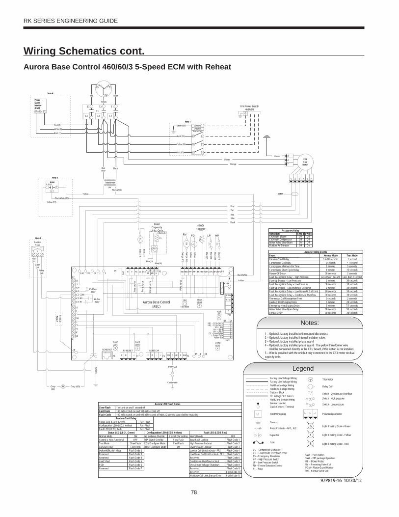
78
RK SERIES ENGINEERING GUIDE
Wiring Schematics cont.Aurora Base Control 460/60/3 5-Speed ECM with Reheat
Slow FlashFast FlashFlash Code
Status LED (LED1, Green)Configuration LED (LED2, Yellow)Fault LED (LED3, Red)
Status LED (LED1, Green)Normal ModeControl is Non-FunctionalTest ModeLockout ActiveDehumidification ModeReservedReservedLoad ShedESD
1 second on and 1 second off
Random Start DelayFast Flash
OFFON
Slow FlashFast Flash
Flash Code 2Flash Code 3
Flash Code 6
Flash Code 4Flash Code 5
Aurora LED Flash Codes
100 milliseconds on and 100 milliseconds off100 milliseconds on and 400 milliseconds off with a 2 second pause before repeating
Reserved Flash Code 7
Configuration LED (LED2, Yellow) Fault LED (LED3, Red)
Fast FlashFast Flash
No Software Overide Flash ECM SettingDIP Switch Overide Slow Flash
Normal ModeInput Fault LockoutHigh Pressure LockoutLow Pressure Lockout
Low Water Coil Limit Lockout - FP1Low Air Coil Limit Lockout - FP2
ReservedCondensate Overflow LockoutOver/Under Voltage ShutdownReservedReservedAir/Water Coil Limit Sensor Error
Flash Code 1OFF
Flash Code 2Flash Code 3Flash Code 4Flash Code 5
Flash Code 8
Flash Code 6Flash Code 7
Flash Code 9Flash Code 10Flash Code 11
ECM Configure Mode Fast FlashReset Configure Mode Off
Thermistor
Relay Coil
Switch - Condensate Overflow
Switch - High pressure
Switch - Low pressure
Polarized connector
Factory Low Voltage WiringFactory Line Voltage WiringField Low Voltage WiringField Line Voltage WiringOptional BlockDC Voltage PCB Traces
Internal JunctionQuick Connect Terminal
Field Wiring Lug
Ground
Relay Contacts – N.O., N.C.
Field Zone Sensor Wiring
Legend
L1
Capacitor
T
123
CC – Compressor ContactorCO – Condensate Overflow SensorES – Emergency ShutdownHP – High Pressure SwitchLP – Low Pressure SwitchFD – Freeze Detection SensorF1 – Fuse
Fuse
Light Emitting Diode - GreenG
Light Emitting Diode - YellowY
Light Emitting Diode - RedR
SW1 – Push buttonSW2 – DIP package 8 positionRB – Blower RelayRV – Reversing Valve CoilPGM – Phase Guard MonitorRH – Reheat Valve Coil
1 – Optional, factory installed unit mounted disconnect.2 – Optional, factory installed internal isolation valve.3 – Optional, factory installed phase guard4 – Optional, factory installed phase guard. The yellow transformer wire shall be connected directly to the CPU board, if this option is not installed.5 – Wire is provided with the unit but only connected to the X13 motor on dual capacity units.
Notes:
Accessory Relay
Cycle with BlowerCycle with CompressorWater Valve Slow OpenOutdoor Air Damper
SW2-4 SW2-5On OnOff OffOn OffOff On
Operation
Event Normal Mode Test ModeRandom Start DelayCompressor On DelayCompressor Minimum On TimeCompressor Short Cycle DelayBlower Off DelayFault Recognition Delay – High PressureStart-Up Bypass – Low PressureFault Recognition Delay – Low PressureStart-Up Bypass – Low Water/Air Coil LimitFault Recognition Delay – Low Water/Air Coil LimitFault Recognition Delay – Condensate OverflowThermostat Call Recognition TimeAuxiliary Heat Staging DelayEmergency Heat Staging Delay
Less than 1 second
5 to 80 seconds 1 second5 seconds < 1 second
30 seconds 2 secondsLess than 1 second
2 minutes 5 seconds4 minutes 15 seconds
2 minutes
2 minutes
30 seconds30 seconds 30 seconds
30 seconds30 seconds
30 seconds30 seconds30 seconds
2 seconds 2 seconds5 minutes2 minutes
20 seconds7.5 seconds
Aurora Timing Events
Reheat Delay 30 seconds 30 secondsWater Valve Slow Open Delay 90 seconds 90 seconds
Transformer
Blue460V
Black
24V
2 1 3
IsolationValve
Red (51)
Green (50)
White (52)
Note 2
Note 2Red (53)
CC
470
470Resistor
Violet (14)
Black (15)
Orange (01)
Orange (02)
Condensate
Brown (23)Green
RV
HPLP
T
FDRV
Blue (07)
Blue (08)
Black (09)
Black (10)
Yellow
Yellow
Blue460V
Black
Yellow
L2L3
CCT2T3
L1
T1
T1
T2
T3
Black
Yellow
Red
L1 L2 L3
Phase Guard Monitor (PGM)
C
Y-OUTY
PGM
Black (7)
White (8)
Red (9)
Yellow (91)Black/White (92)
Note 4
Note 5
Note 1
Black (95)
Yellow (96)
DisconnectNeutralGround
L1 L1
L2 L2
L3 L3
Unit Power Supply460/60/3G
Green (93)
Red (97)
123
LN
G
X13Fan
Motor
C45
Green
Orange
Brown
Tan
Gray
BlueRed
Black
Black/White
Black/White
Yellow
RH Gray (60)Gray(61)
Note 5
UltraTech
DualCapacity
Units Only
RCP
CS
Blue(16)Blue(18)
CFM
P13
P4
SW1
P5JW2
P9
LO
O/B
Y2WDH
P8 P7
RS485 NET RS485 NET
P6
RS485 EXP
P3
SW2
On
Future Use L Output Type
CC – Dual/SingleAcc – Dip 5Acc – Dip 4
RV – B/OFP2 – 15°F/30°FFP1 – 15°F/30°F
Com1LED5
Com2LED5
Test Mode
F1-3A
P1
C
PWM
12345678
ALMALGACC COMACC NOACC NC
RC
GY1
EH2CEH1CCOC R - +C R - +
Off
FaultLED1
R
StatusLED3
ConfigLED2
CC2 CC F C R F FG CC CCGCC2HI
CC2LO
CC2G REV REV FP1 FP1 FP2 FP2 LPS LPS HPS HPS
Aurora Base Control(ABC)
K1-RV Relay
K2-CC Relay
K3-CC2 Relay
K4-Fan RelayK5-Alarm Relay
K6-Acc Relay
F
R
C
CCGY1C
R
ESLS
P2
EH1
YG G
G
97P819-16 10/30/12
79
RK SERIES ENGINEERING GUIDE
Engineering Guide Specifi cationsGeneralFurnish and install water source heat pumps as indicated on the plans. Equipment shall be completely assembled, piped and internally wired. Capacities and characteristics as listed in the schedule and the specifi cations that follow. The reverse cycle heating/cooling units shall be either suspended type with horizontal air inlet and discharge or fl oor mounted type with horizontal air inlet and vertical upfl ow air discharge. Units shall be AHRI/ISO 13256-1 certifi ed and listed by a nationally recognized safety-testing laboratory or agency, such as ETL Testing Laboratory. Each unit shall be computer run-tested at the factory with conditioned water and operation verifi ed to catalog data. Each unit shall be mounted on a pallet and shipped in a corrugated box or stretch-wrapped. The units shall be designed to operate with entering liquid temperature between 20°F and 120°F [-6.7°C and 48.9°C].
Casing and CabinetThe cabinet shall be fabricated from heavy-gauge galvanized steel and fi nished with optional corrosion-resistant powder coating. This corrosion protection system shall meet the stringent 1000 hour salt spray test per ASTM B117. The interior shall be insulated with 1/2 in. thick, multi-density, cleanable aluminum foil coated glass fi ber with edges sealed or tucked under fl anges to prevent the introduction of glass fi bers into the discharge air. Standard cabinet panel insulation must meet NFPA 90A requirements, air erosion and mold growth limits of UL-181, stringent fungal resistance test per ASTM-C1071 and ASTM G21, and shall meet zero level bacteria growth per ASTM G22. Unit insulation must meet these stringent requirements or unit(s) will not be accepted.
One (horizontal) to two (vertical) blower and two compressor compartment access panels shall be ‘lift-out’ removable with supply and return ductwork in place.
A duct collar shall be provided on the supply air opening. Standard size 1 in. [2.54 cm] MERV 4 fi lters shall be provided with each unit. Units shall have a return air fi lter rack that is fi eld convertible from 1 in. [2.54 cm] to 2 in. [5.1 cm]. The units shall have an insulated divider panel between the air handling section and the compressor section to minimize the transmission of compressor noise. Vertical units shall be supplied with left or right horizontal air inlet and top vertical air discharge. Horizontal units shall be supplied with left or right air inlet and side or end air discharge.
The compressor shall be double isolation mounted using selected durometer grommets to provide vibration free compressor mounting. The compressor mounting bracket shall be acoustically deadened galvanized steel to prevent vibration transmission to the cabinet.
Option: AlpinePure MERV 13 fi lter - A 2 in. thick [51 mm] MERV 13 fi lter can help fulfi ll a credit under the LEED Rating System. Its low initial resistance promotes low energy consumption (0.21 in. w.g. @ 300 fpm) and provides nearly twice the life of a standard fi lter (300 fpm vs. standard 500 fpm application).
Option: A Super Quiet Sound package shall include multi-density full coverage compressor blanket.
Option: An internally mounted low pressure drop (high Cv) water solenoid valve shall be factory installed for use in variable speed pumping applications.
Option: An internally mounted automatic fl ow regulator shall be set to 3 gpm/ton to deliver optimal fl ow to the unit.
Refrigerant CircuitAll units shall utilize the non-ozone depleting and low global warming potential refrigerant R-410A. All units shall contain a sealed refrigerant circuit including a hermetic motor-compressor, bidirectional thermostatic expansion valve, fi nned tube air-to-refrigerant heat exchanger, reversing valve, coaxial tube water-to-refrigerant heat exchanger, optional hot water generator coil, and service ports.
Compressors shall be high-effi ciency single speed rotary or scroll type designed for heat pump duty and mounted on vibration isolators. The compressor shall be double isolation mounted using selected durometer grommets to provide vibration free compressor mounting.
Option: AlumiSeal electro-coated air coil.
The coaxial water-to-refrigerant heat exchanger shall be designed for low water pressure drop and constructed of a convoluted copper (cupronickel option) inner tube and a steel outer tube. Refrigerant to air heat exchangers shall utilize enhanced corrugated lanced aluminum fi ns and rifl ed aluminum tube construction rated to withstand 600 psig (4135 kPa) refrigerant working pressure. Refrigerant to water heat exchangers shall be of copper inner water tube and steel refrigerant outer tube design, rated to withstand 600 psig (4135 kPa) working refrigerant pressure and 450 psig (3101 kPa) working water pressure.
The thermostatic expansion valve shall provide proper superheat over the entire liquid temperature range with minimal “hunting.” The valve shall operate bidirectionally without the use of check valves.
Option: Cupronickel refrigerant to water heat exchanger shall be of copper-nickel inner water tube and steel refrigerant outer tube design, rated to withstand 600 psig (4135 kPa) working refrigerant pressure and 450 psig (3101 kPa) working water pressure. Water lines shall also be of cupronickel construction.
Option: Hot water generator - Internal double wall vented hot water generator coil refrigerant to water heat exchangers shall be of copper inner water tube and steel refrigerant outer tube design, rated to withstand 600 psig (4135 kPa) working refrigerant pressure and 450 psig (3101 kPa) working water pressure.
80
RK SERIES ENGINEERING GUIDE
Engineering Guide Specifi cations cont.Option: ThermaShield coated water-to-refrigerant heat exchanger, water lines and refrigerant suction lines shall be insulated to prevent condensation at low liquid temperatures below 50°F.
Option: AlpinePure hot gas bypass
Option: AlpinePure hot gas reheat
Blower Motor and AssemblyThe blower shall be a direct drive centrifugal type with a dynamically balanced wheel. The housing and wheel shall be designed for quiet low outlet velocity operation. The blower housing shall be removable from the unit without disconnecting the supply air ductwork for servicing of the blower motor. The blower motor shall be isolated from the housing by rubber grommets. The motor shall be permanently lubricated and have thermostatic overload protection.
Option: PSC blower motor shall be a three-speed PSC type.
Option: 5-Speed ECM blower motor shall be a 5-speed ECM type. The 5-speed ECM blower motor shall be soft starting, shall maintain constant torque over its operating static range, and shall provide 5 speed settings. The blower motor shall be isolated from the housing by rubber grommets. The motor shall be permanently lubricated and have thermostatic overload protection. 5-speed ECM motors shall be long-life ball bearing type.
Option: Variable speed ECM blower motor shall be a variable speed ECM type. The variable speed ECM blower motor shall be soft starting, shall maintain constant cfm over its operating static range, and shall provide 12 cfm settings. Variable speed ECM motors shall be long-life ball bearing type.
Option: High static blower motors shall be available on certain PSC and variable speed ECM models.
ElectricalA control box shall be located within the unit compressor compartment and shall contain a 50VA or 75VA transformer, 24 volt activated, 2 pole compressor contactor, terminal block for thermostat wiring and solid-state controller for complete unit operation. Electromechanical operation WILL NOT be accepted. Units shall be name-plated for use with time delay fuses or HACR circuit breakers. Unit controls shall be 24 volt and provide heating or cooling as required by the remote thermostat/sensor.
An Aurora microprocessor-based controller that interfaces with a multi-stage electronic thermostat to monitor and control unit operation shall be provided. The control shall provide operational sequencing, blower speed control, high and low pressure switch monitoring, freeze detection, condensate overfl ow sensing, lockout mode control, LED status and fault indicators, fault memory, fi eld selectable options and accessory output. The control shall provide fault retry three times before locking out to limit nuisance trips.
A detachable terminal block with screw terminals will be provided for fi eld control wiring. All units shall have knockouts for entrance of low and line voltage wiring. The blower motor and control box shall be harness plug wired for easy removal.
Option: IntelliStart® (compressor soft starter) shall be factory installed for use in applications that require low starting amps, reduced compressor start-up noise, off-grid, and improved start-up behavior. IntelliStart shall reduce normal starting current up to 60%.
PipingSupply and return water connections shall be FPT copper fi ttings fi xed to the corner post, which eliminate the need for backuppipe wrenches.
With vertical units, the condensate connection shall be a 3/4 in. [19.1 mm] PVC socket with internally-trapped hose that can be routed to front or side corner post locations.
Hanger Kit(included with horizontal units only - fi eld installed) The hanger kit shall consist of galvanized steel brackets, bolts, lock washers, and isolators and shall be designed to fasten to the unit bottom panel for suspension from 3/8 in. threaded rods. Unit sizes 009-060 shall require four brackets and unit sizes 070-072 shall require fi ve brackets. Brackets shall not inhibit fi lter removal in any way.
AccessoriesThermostat (field-installed)A multi-stage auto-changeover electronic digital thermostat shall be provided. The thermostat shall offer two heating stages and one cooling stage with precise temperature control. An OFF-HEAT-AUTO-COOL-EMERG system switch, OFF-AUTO blower switch, and indicating LEDs shall be provided. The thermostat shall display in °F or °C.
Hose Kits – Ball Valves (field-installed)A fl exible steel braid hose featuring Kevlar® reinforced EPDM core with ANSI 302/304 stainless steel outer braid and fi re rated materials per ASTM E 84-00 (NFPA 255, ANSI/UL 723 & UBC 8-1). Ball valve at one end; swivel connector with adapter at the other end (swivel to adapter connection via fi ber or EPDM gasket). Swivel connection provides union between heat pump and piping system. The hoses feature brass fi ttings, stainless steel ferrules. A full port ball valve shall be provided with integral P/T (pressure/temperature) port on supply hose.
Specifi cations:• Temperature range of 35°F [2°C] to 180°F [82°C].• Max. working pressure of 400 psi [2757 kPa] for 1/2 in. and 3/4 in. hose kits; max. working pressure of 350 psi [kPa] for 1 in. and 1-1/4 in. hose kits.
81
RK SERIES ENGINEERING GUIDE
Engineering Guide Specifi cations cont.Hose Kits – Automatic Balancing and Ball Valves(field-installed)A flexible steel braid hose featuring Kevlar® reinforced EPDM core with ANSI 302/304 stainless steel outer braid and fire rated materials per ASTM E 84-00 (NFPA 255, ANSI/UL 723 & UBC 8-1). Ball valve at one end; swivel connector with adapter at the other end (swivel to adapter connection via fiber or EPDM gasket). Swivel connection provides union between heat pump and piping system. The hoses feature brass fittings, stainless steel ferrules. A full port ball valve shall be provided with integral P/T (pressure/temperature) port on supply hose and automatic balancing valve with integral P/T ports and full port ball valve on return hose.
Specifi cations:• Temperature range of 35°F [2°C] to 180°F [82°C]• Max. working pressure of 400 psi [2757 kPa] for 1/2 in. and 3/4 in. hose kits; max. working pressure of 350 psi [2413 kPa] for 1 in. and 1-1/4 in. hose kits• Minimum burst pressure of four times working pressure
Hose Kits – Automatic Balancing and Ball Valves with ‘Y’ strainer (field-installed)A fl exible steel braid hose featuring Kevlar® reinforced EPDM core with ANSI 302/304 stainless steel outer braid and fi re rated materials per ASTM E 84-00 (NFPA 255, ANSI/UL 723 & UBC 8-1). Ball valve at one end; swivel connector with adapter at the other end (swivel to adapter connection via fi ber or EPDM gasket). Swivel connection provides union between heat pump and piping system. The hoses feature brass fi ttings, stainless steel ferrules. A “y” strainer is provided on one end for fl uid straining and integral “blowdown” valve. A full port ball valve shall be provided with integral P/T (pressure/temperature) port on supply hose and automatic balancing valve with integral P/T ports and full port ball valve on return hose.
Specifi cations:• Temperature range of 35°F [2°C] to 180°F [82°C]• Max. working pressure of 400 psi [2756 kPa] for 1/2 in. and 3/4 in. hose kits; max. working pressure of 350 psi [2413 kPa] for 1 in. and 1-1/4 in. hose kits• Minimum burst pressure of four times working pressure
Hot Water Pump Kit (field-installed)An accessory pump kit is available for hot water generation option. This kit includes hot water pump, fi ttings, and water heater kit necessary for potable water application. Order DPK5 for use with Aurora.

82
RK SERIES ENGINEERING GUIDE
Notes
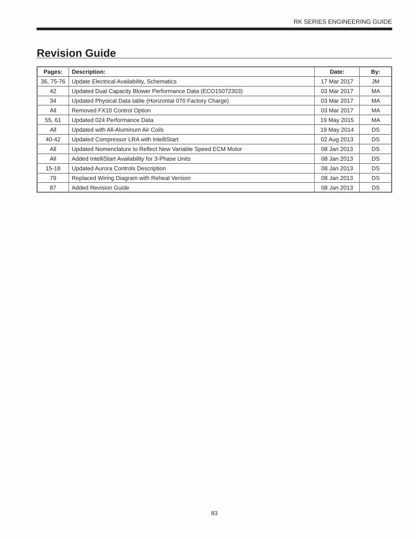
83
RK SERIES ENGINEERING GUIDE
Pages: Description: Date: By:36, 75-76 Update Electrical Availability, Schematics 17 Mar 2017 JM
42 Updated Dual Capacity Blower Performance Data (ECO15072303) 03 Mar 2017 MA
34 Updated Physical Data table (Horizontal 070 Factory Charge) 03 Mar 2017 MA
All Removed FX10 Control Option 03 Mar 2017 MA
55, 61 Updated 024 Performance Data 19 May 2015 MA
All Updated with All-Aluminum Air Coils 19 May 2014 DS
40-42 Updated Compressor LRA with IntelliStart 02 Aug 2013 DS
All Updated Nomenclature to Reflect New Variable Speed ECM Motor 08 Jan 2013 DS
All Added IntelliStart Availability for 3-Phase Units 08 Jan 2013 DS
15-18 Updated Aurora Controls Description 08 Jan 2013 DS
79 Replaced Wiring Diagram with Reheat Version 08 Jan 2013 DS
87 Added Revision Guide 08 Jan 2013 DS
Revision Guide

Product: RK SeriesType: Water Source/Geothermal Heat PumpSize: 0.75-6 Ton
Document Type: Engineering GuideForm: 146.08-EG1 (0317)Supercedes: 146.00-EG8 (0514)
©2017 The manufacturer works continually to improve its products. As a result, the design and specifi cations of each product at the time of order may be changed without notice. Purchaser’s approval of this data set signifi es that the equipment is acceptable under the provisions of the job specifi cation. Statements and other information contained herein are not express warranties and do not form the basis of any bargain between the parties, but are merely the manufacturer’s opinion or commendation of its products.