rfid door lock - cal poly
TRANSCRIPT
1
RFID Door Lock
by
Ralph Ting
Mackenzie Keane
Senior Project
Electrical Engineering Department
California Polytechnic State University
San Luis Obispo
2014
2
Table of Contents
List of Tables and Figures 3
Abstract 4
Chapter 1: Introduction 5
Chapter 2: Requirements and Specifications 6
Chapter 3: Functional Decomposition 8
Chapter 4: Conclusion and Future Work 14
References 16
Appendix A. Senior Project Analysis 17
Appendix B. C Code 22
3
List of Tables and Figures
Tables
1. RFID Door Lock Requirements and Specifications 6
2. Level 0 Functionality Table 8
3. Cost Estimates 13
Figures
1. Level 0 Block Diagram 7
2. Level 1 Block Diagram 10
3. Level 2 Voltage Regulator Block Diagram 11
4. Level 2 Amplifier Block Diagram 10
(a) Inverting Amplifier LTspice Schematic 11
5. Level 2 RFID/Arduino Block Diagram 13
6. Estimated Gantt Chart 19
7. Actual Gantt Chart 20
4
Abstract
The RFID Door Lock is a lock that is simple to install and allows the user to easily lock and
unlock doors. It will contain a RFID reader/writer and a magnetic door lock for simple use. All the user
will need is an RFID tag to be able to unlock and lock the door. A LED will be used to let the user know
when the door is in fact locked. The components included in the module are small and compact.
Additionally, the door lock is simple and easy to install. It does not require the consumer to disassemble
the door or doorframe as the door lock are merely attachments. This is also leaves the consumer with the
option of using their original lock and key if they so choose. All in all, this RFID door lock should be a
simple and cost effective upgrade to the average consumer’s security and convenience.
5
Chapter 1: Introduction
The project that we will be working on is an RFID door lock that will be available to the general
public at an affordable price. The goal of this project is to create a more convenient way to unlock your
door than the traditional key. In the key’s place is an RFID tag that will unlock the door by proximity.
However, the improvements of this RFID door lock must outweigh the complications of implementation.
The list of customer needs (in the Requirements and Specifications section) was constructed with that
fundamental goal in mind. The design consists of two components. The first component is the actual door
lock that must be installed in the doorframe. This will be controlled by a magnetic lock and will need to
be powered. The second component is a relatively small module that you can install anywhere near the
door. This module is responsible for the RFID sensing.
Chapter 2 goes over the requirements and specifications determined for the RFID door lock. The
requirements are inspired by surveys of various groups as well as personal interest. The specifications are
designed in order to meet these requirements. These are created before the actual design of the RFID door
lock had been created so the requirements and specifications may not exactly meet the final product.
However, the final product is still designed with these ideas in mind.
In the Functional Decomposition (Chapter 3), the design of the final product is shown and
explained. This chapter also documents the tests and complications confronted throughout the design. The
design is split into 5 modules which were tackled individually until finally bringing the whole product
together. The necessity of each module is included.

6
Chapter 2: Requirements and Specifications
Customer Needs Assessment
As stated before, the improvements must outweigh the complications of implementation. There has to be a reason to
buy this door lock and replace their own door locks with it. That is why convenience and reliability are the first two
customer needs. These are possibly the most important and apply to almost every engineering specification and do
not require as much explanation as the other three.
One of the more interesting requirements is the hassle-free installation. Of course the door lock will require minor
assembly but the process of installation should not be overly complicated. The device should be a complex system
simplified for the common consumer. Another important feature is the need for failsafes and overrides. In cases
where the owner may lose their keys, the owner of the door lock should not be denied access to the door at any time.
There should always be a way in that is only accessible to the customer. These needs are listed in Table 1.
Requirements and Specifications
The requirements and specifications were generated with the customer needs as a basis. These specifications are
listed in Table 1. To the left of the Engineering Specifications are the Customer Needs that each specification meets.
The justification on right details the thinking and reasoning behind the specifications and how they fit the customer
needs.
TABLE 1
RFID SECURITY DOOR LOCK REQUIREMENTS AND SPECIFICATIONS
Customer Needs Engineering
Specifications
Justification
1 Unlocks in the presence of RFID tag within
20cm
This will make the door
easier to unlock than a
regular key
2, 3 The physical door lock should be thinner
than the doorframe
This way the door lock
will be hidden and
avoid external
tampering
1, 3 Should be easy enough to install in 5 steps
maximum
Simple enough for
anyone to install
1, 2 The lock should be powered by a 9V source
so that it can run on 9V batteries as a
backup
This is a common
voltage to find within a
house
Customer Needs
1. Needs to be convenient so that people will have an easier time unlocking their doors
2. Needs to be reliable so that people can trust the door lock
3. Hassle-free to install so that anyone can install it into their home with ease
4. Failsafe and overrides in case the RFID key is lost or the power fails
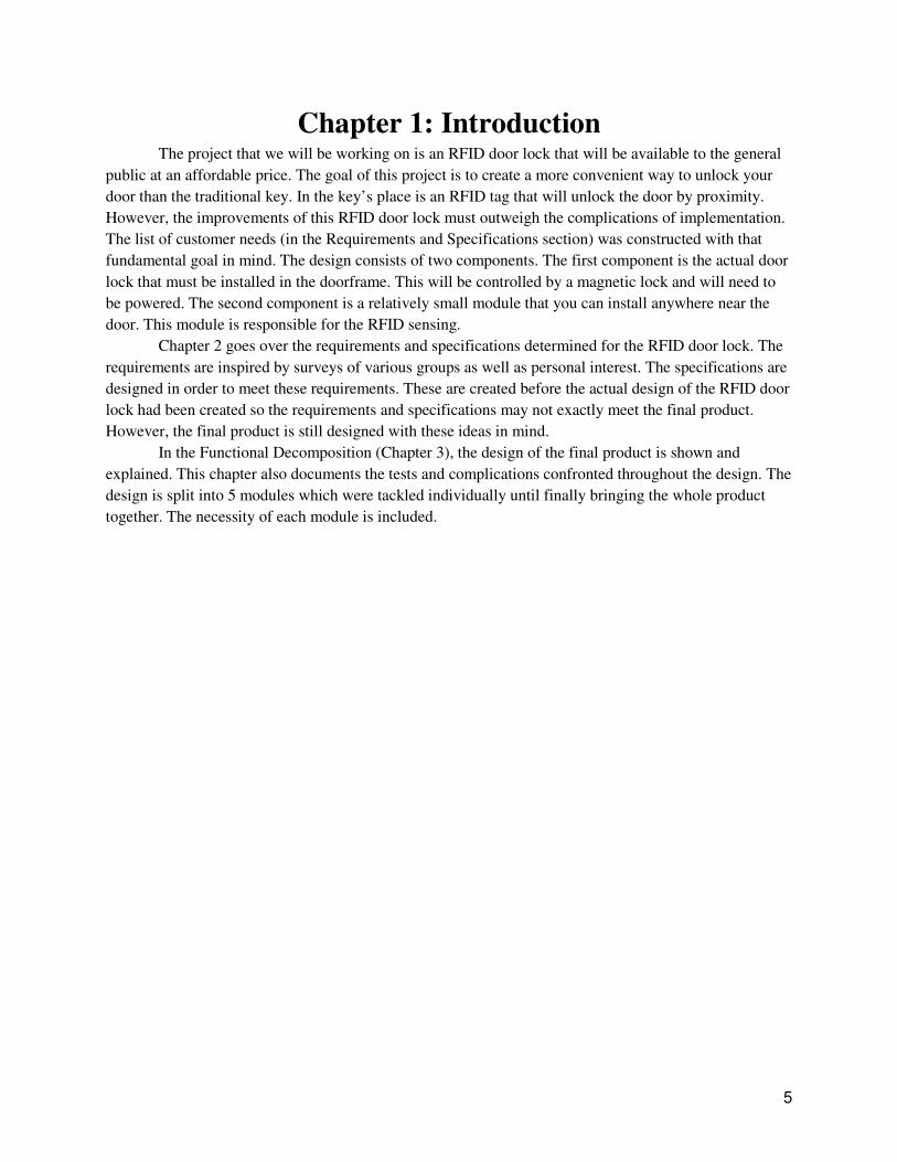
Chapter 3: Functional Decomposition At its core, the RFID Door Lock will have 3 inputs and 2 outputs. Power is an important input and will
supply the RFID Door Lock with the necessary voltage and currents to operate. It will be operated with 8.5V supply
and will be drawn through an AC adapter. The second input is the RFID Sensor Input. This is where the RFID tag
information will be entering the system. As for
the signal whether or not to keep the door locked or unlock the door. These ideas are graphically represented in
Figure 1 and Table 2.
FIGURE 1: LEVEL 0 BLOCK DIAGRAM
Input Description
Power Supplies voltage to the RFID Door
Lock and powers it for all
functions.
RFID Sensor
Input
Scans for RFID tags and unlocks
or remains locked depending on
settings and RFID tag.
The initial Level 1 decomposition, the RFID Door Lock can be broken down into 5 basic components. The
RFID Input (the RFID tag) goes into an RFID sensor that will then be placed into the MCU (or Microcontroller).
Based on the programming and the settings s
Chapter 3: Functional DecompositionAt its core, the RFID Door Lock will have 3 inputs and 2 outputs. Power is an important input and will
oor Lock with the necessary voltage and currents to operate. It will be operated with 8.5V supply
and will be drawn through an AC adapter. The second input is the RFID Sensor Input. This is where the RFID tag
information will be entering the system. As for the outputs, the Unlock/Lock is where the RFID Door Lock sends
the signal whether or not to keep the door locked or unlock the door. These ideas are graphically represented in
FIGURE 1: LEVEL 0 BLOCK DIAGRAM
TABLE 2
LEVEL 0 FUNCTIONALITY TABLE
Output Description
Supplies voltage to the RFID Door
Lock and powers it for all
Unlock/Lock Will unlock the door or remain
locked depending on the RFID tag
and settings.
for RFID tags and unlocks
or remains locked depending on
settings and RFID tag.
The initial Level 1 decomposition, the RFID Door Lock can be broken down into 5 basic components. The
RFID Input (the RFID tag) goes into an RFID sensor that will then be placed into the MCU (or Microcontroller).
Based on the programming and the settings set by the User Control, the MCU will then send instructions to the
7
Chapter 3: Functional Decomposition
At its core, the RFID Door Lock will have 3 inputs and 2 outputs. Power is an important input and will
oor Lock with the necessary voltage and currents to operate. It will be operated with 8.5V supply
and will be drawn through an AC adapter. The second input is the RFID Sensor Input. This is where the RFID tag
the outputs, the Unlock/Lock is where the RFID Door Lock sends
the signal whether or not to keep the door locked or unlock the door. These ideas are graphically represented in
Will unlock the door or remain
locked depending on the RFID tag
The initial Level 1 decomposition, the RFID Door Lock can be broken down into 5 basic components. The
RFID Input (the RFID tag) goes into an RFID sensor that will then be placed into the MCU (or Microcontroller).
et by the User Control, the MCU will then send instructions to the
Magnetic Relay and the LCD Module. Whatever is sent in to the LCD Module is outputted as the LCD Display and
can be thought of as the actual LCD screen. After the Magnetic Relay receives in
magnetic relay will then flip the circuit towards the Door Lock. The Door Lock will then output the Unlock/Lock
signal. The Door Lock can be considered as the physical door lock in the doorframe. The power will be supplied to
all of the blocks. Figure 2 displays this graphically. This Level 1 design is inspired by the Cytron Industries RFID
Door Lock (reference 11).
However, as the design began to be finalized, there was no longer a use for the magnetic relay and the user
control was left out. These only complicated the installation process. Instead the completed level 1 block diagram
uses a voltage regulator and an amplifier stage to power an electromagnetic lock. These components are much
smaller and do not require disassemblin
strength of the door lock beyond the capabilities of the Arduino microcontroller.
FIGURE 2: LEVEL 1 BLOCK DIAGRAM
This Level 1 diagram can be broken down into three more detailed
are for the voltage regulator, the RFID-
broken down even further in the following pages.
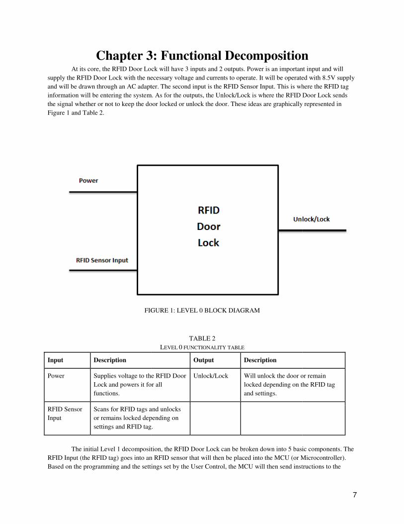
Magnetic Relay and the LCD Module. Whatever is sent in to the LCD Module is outputted as the LCD Display and
can be thought of as the actual LCD screen. After the Magnetic Relay receives instructions from the MCU, the
magnetic relay will then flip the circuit towards the Door Lock. The Door Lock will then output the Unlock/Lock
signal. The Door Lock can be considered as the physical door lock in the doorframe. The power will be supplied to
ll of the blocks. Figure 2 displays this graphically. This Level 1 design is inspired by the Cytron Industries RFID
However, as the design began to be finalized, there was no longer a use for the magnetic relay and the user
l was left out. These only complicated the installation process. Instead the completed level 1 block diagram
uses a voltage regulator and an amplifier stage to power an electromagnetic lock. These components are much
smaller and do not require disassembling a door or doorframe. Using the voltage regulator, we can increase the
strength of the door lock beyond the capabilities of the Arduino microcontroller.
FIGURE 2: LEVEL 1 BLOCK DIAGRAM
This Level 1 diagram can be broken down into three more detailed Level 2 block diagrams. These diagrams
-Arduino connection, and the inverting amplifier. The following modules are
broken down even further in the following pages.
8
Magnetic Relay and the LCD Module. Whatever is sent in to the LCD Module is outputted as the LCD Display and
structions from the MCU, the
magnetic relay will then flip the circuit towards the Door Lock. The Door Lock will then output the Unlock/Lock
signal. The Door Lock can be considered as the physical door lock in the doorframe. The power will be supplied to
ll of the blocks. Figure 2 displays this graphically. This Level 1 design is inspired by the Cytron Industries RFID
However, as the design began to be finalized, there was no longer a use for the magnetic relay and the user
l was left out. These only complicated the installation process. Instead the completed level 1 block diagram
uses a voltage regulator and an amplifier stage to power an electromagnetic lock. These components are much
g a door or doorframe. Using the voltage regulator, we can increase the
Level 2 block diagrams. These diagrams
Arduino connection, and the inverting amplifier. The following modules are
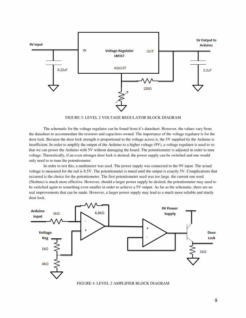
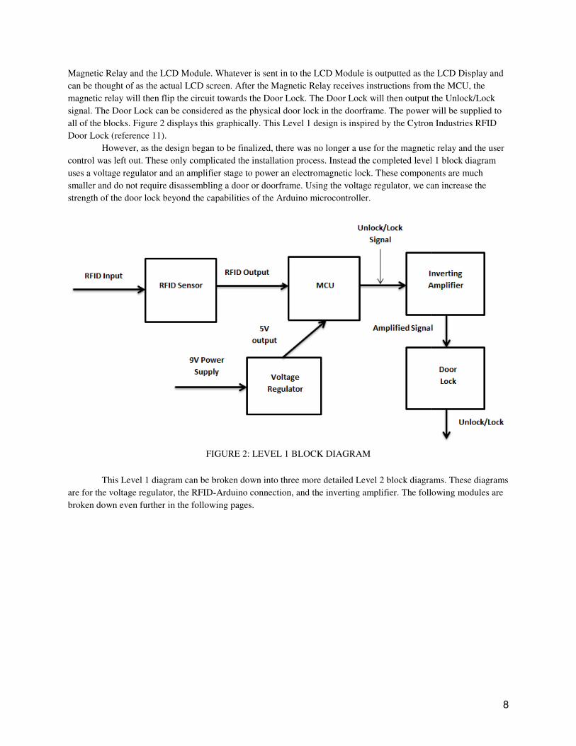
FIGURE 3: LEVEL 2 VOLTAGE REGULATOR BLOCK
The schematic for the voltage regulator can be found from it’s datasheet. However, the values vary from
the datasheet to accommodate the resistors and capacitors owned. The importance of the voltage regulator is for the
door lock. Because the door lock strength is proportional to the voltage across it, the 5V supplied by the Arduino is
insufficient. In order to amplify the output of the Arduino to a higher voltage (9V), a voltage regulator is used to so
that we can power the Arduino with 5V withou
voltage. Theoretically, if an even stronger door lock is desired, the power supply can be switched and one would
only need to re-tune the potentiometer.
In order to test this, a multimet
voltage is measured for the rail is 8.5V. The potentiometer is tuned until the output is exactly 5V. Complications that
occurred is the choice for the potentiometer. The first potentio
(5kohms) is much more effective. However, should a larger power supply be desired, the potentiometer may need to
be switched again to something even smaller in order to achieve a 5V output. As far as the schem
real improvements that can be made. However, a larger power supply may lead to a much more reliable and sturdy
door lock.
FIGURE 4: LEVEL 2 AMPLIFIER BLOCK DIAGRAM
FIGURE 3: LEVEL 2 VOLTAGE REGULATOR BLOCK DIAGRAM
The schematic for the voltage regulator can be found from it’s datasheet. However, the values vary from
the datasheet to accommodate the resistors and capacitors owned. The importance of the voltage regulator is for the
r lock strength is proportional to the voltage across it, the 5V supplied by the Arduino is
insufficient. In order to amplify the output of the Arduino to a higher voltage (9V), a voltage regulator is used to so
that we can power the Arduino with 5V without damaging the board. The potentiometer is adjusted in order to tune
voltage. Theoretically, if an even stronger door lock is desired, the power supply can be switched and one would
In order to test this, a multimeter was used. The power supply was connected to the 9V input. The actual
voltage is measured for the rail is 8.5V. The potentiometer is tuned until the output is exactly 5V. Complications that
occurred is the choice for the potentiometer. The first potentiometer used was too large. the current one used
(5kohms) is much more effective. However, should a larger power supply be desired, the potentiometer may need to
be switched again to something even smaller in order to achieve a 5V output. As far as the schem
real improvements that can be made. However, a larger power supply may lead to a much more reliable and sturdy
FIGURE 4: LEVEL 2 AMPLIFIER BLOCK DIAGRAM
9
The schematic for the voltage regulator can be found from it’s datasheet. However, the values vary from
the datasheet to accommodate the resistors and capacitors owned. The importance of the voltage regulator is for the
r lock strength is proportional to the voltage across it, the 5V supplied by the Arduino is
insufficient. In order to amplify the output of the Arduino to a higher voltage (9V), a voltage regulator is used to so
t damaging the board. The potentiometer is adjusted in order to tune
voltage. Theoretically, if an even stronger door lock is desired, the power supply can be switched and one would
er was used. The power supply was connected to the 9V input. The actual
voltage is measured for the rail is 8.5V. The potentiometer is tuned until the output is exactly 5V. Complications that
meter used was too large. the current one used
(5kohms) is much more effective. However, should a larger power supply be desired, the potentiometer may need to
be switched again to something even smaller in order to achieve a 5V output. As far as the schematic, there are no
real improvements that can be made. However, a larger power supply may lead to a much more reliable and sturdy
10
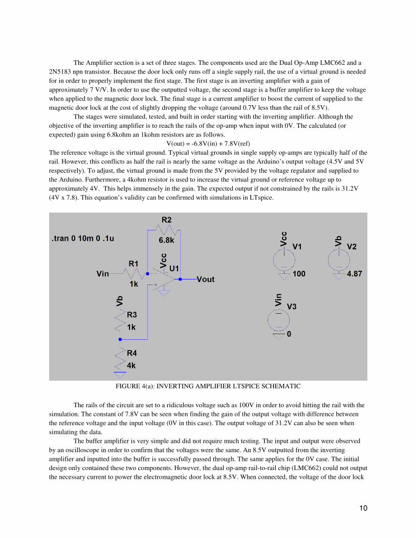
The Amplifier section is a set of three stages. The components used are the Dual Op-Amp LMC662 and a
2N5183 npn transistor. Because the door lock only runs off a single supply rail, the use of a virtual ground is needed
for in order to properly implement the first stage. The first stage is an inverting amplifier with a gain of
approximately 7 V/V. In order to use the outputted voltage, the second stage is a buffer amplifier to keep the voltage
when applied to the magnetic door lock. The final stage is a current amplifier to boost the current of supplied to the
magnetic door lock at the cost of slightly dropping the voltage (around 0.7V less than the rail of 8.5V).
The stages were simulated, tested, and built in order starting with the inverting amplifier. Although the
objective of the inverting amplifier is to reach the rails of the op-amp when input with 0V. The calculated (or
expected) gain using 6.8kohm an 1kohm resistors are as follows.
V(out) = -6.8V(in) + 7.8V(ref)
The reference voltage is the virtual ground. Typical virtual grounds in single supply op-amps are typically half of the
rail. However, this conflicts as half the rail is nearly the same voltage as the Arduino’s output voltage (4.5V and 5V
respectively). To adjust, the virtual ground is made from the 5V provided by the voltage regulator and supplied to
the Arduino. Furthermore, a 4kohm resistor is used to increase the virtual ground or reference voltage up to
approximately 4V. This helps immensely in the gain. The expected output if not constrained by the rails is 31.2V
(4V x 7.8). This equation’s validity can be confirmed with simulations in LTspice.
FIGURE 4(a): INVERTING AMPLIFIER LTSPICE SCHEMATIC
The rails of the circuit are set to a ridiculous voltage such as 100V in order to avoid hitting the rail with the
simulation. The constant of 7.8V can be seen when finding the gain of the output voltage with difference between
the reference voltage and the input voltage (0V in this case). The output voltage of 31.2V can also be seen when
simulating the data.
The buffer amplifier is very simple and did not require much testing. The input and output were observed
by an oscilloscope in order to confirm that the voltages were the same. An 8.5V outputted from the inverting
amplifier and inputted into the buffer is successfully passed through. The same applies for the 0V case. The initial
design only contained these two components. However, the dual op-amp rail-to-rail chip (LMC662) could not output
the necessary current to power the electromagnetic door lock at 8.5V. When connected, the voltage of the door lock
would drop to 5.5V. In order to fix this issue, a NPN transistor is added to amplify the current at the cost of some
voltage.
The maximum current outputted from the op
the buffer amplifier is connected to the base terminal of the transistor as its input. A resistor of 1kohm was used
connecting the emitter terminal to round. The collector is tied to the 8.5V rail in order to maximize the output.
Although the output drops from 8.5V to 7.8V (standard 0.7V).
Thanks to the gain, you can use a stronger power supply while respecting the op
example, a 12V supply would be ideal in order to maximize the strength while keeping within a safe range for the
op-amp.
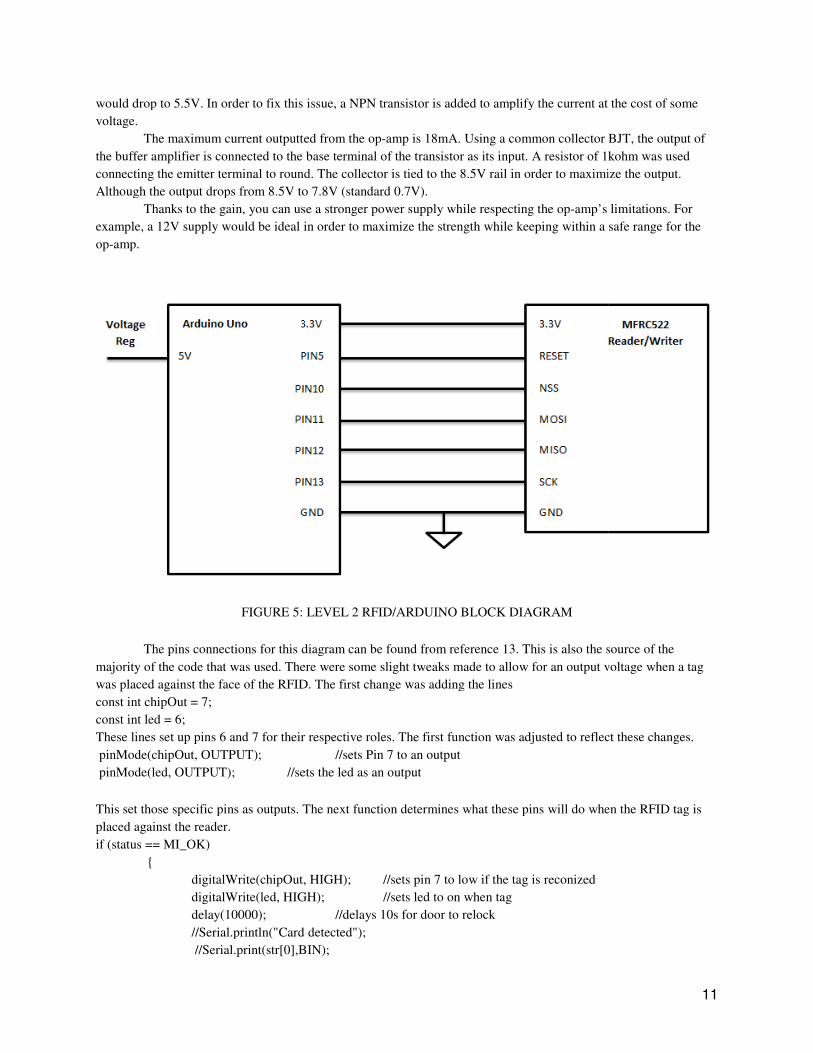
FIGURE 5: LEVEL 2 RFID/ARDU
The pins connections for this diagram can be found from reference 13. This is also the source of the
majority of the code that was used. There were some slight tweaks made to allow for an output voltage when a tag
was placed against the face of the RFID. The first change was adding the lines
const int chipOut = 7;
const int led = 6;
These lines set up pins 6 and 7 for their respective roles. The first function was adjusted to reflect these changes.
pinMode(chipOut, OUTPUT);
pinMode(led, OUTPUT); //sets the led as an output
This set those specific pins as outputs. The next function determines what these pins will do when the RFID tag is
placed against the reader.
if (status == MI_OK)
{
digitalWrite(chipOut, HIGH);
digitalWrite(led, HIGH);
delay(10000);
//Serial.println("Card detected");
//Serial.print(str[0],BIN);
drop to 5.5V. In order to fix this issue, a NPN transistor is added to amplify the current at the cost of some
The maximum current outputted from the op-amp is 18mA. Using a common collector BJT, the output of
the base terminal of the transistor as its input. A resistor of 1kohm was used
connecting the emitter terminal to round. The collector is tied to the 8.5V rail in order to maximize the output.
Although the output drops from 8.5V to 7.8V (standard 0.7V).
Thanks to the gain, you can use a stronger power supply while respecting the op-amp’s limitations. For
example, a 12V supply would be ideal in order to maximize the strength while keeping within a safe range for the
FIGURE 5: LEVEL 2 RFID/ARDUINO BLOCK DIAGRAM
The pins connections for this diagram can be found from reference 13. This is also the source of the
majority of the code that was used. There were some slight tweaks made to allow for an output voltage when a tag
face of the RFID. The first change was adding the lines
These lines set up pins 6 and 7 for their respective roles. The first function was adjusted to reflect these changes.
//sets Pin 7 to an output
//sets the led as an output
This set those specific pins as outputs. The next function determines what these pins will do when the RFID tag is
digitalWrite(chipOut, HIGH); //sets pin 7 to low if the tag is reconized
digitalWrite(led, HIGH); //sets led to on when tag
delay(10000); //delays 10s for door to relock
//Serial.println("Card detected");
//Serial.print(str[0],BIN);
11
drop to 5.5V. In order to fix this issue, a NPN transistor is added to amplify the current at the cost of some
amp is 18mA. Using a common collector BJT, the output of
the base terminal of the transistor as its input. A resistor of 1kohm was used
connecting the emitter terminal to round. The collector is tied to the 8.5V rail in order to maximize the output.
amp’s limitations. For
example, a 12V supply would be ideal in order to maximize the strength while keeping within a safe range for the
The pins connections for this diagram can be found from reference 13. This is also the source of the
majority of the code that was used. There were some slight tweaks made to allow for an output voltage when a tag
These lines set up pins 6 and 7 for their respective roles. The first function was adjusted to reflect these changes.
This set those specific pins as outputs. The next function determines what these pins will do when the RFID tag is
12
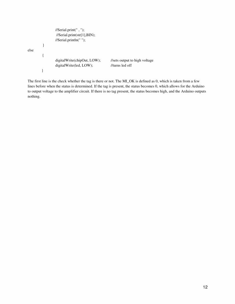
//Serial.print(" , ");
//Serial.print(str[1],BIN);
//Serial.println(" ");
}
else
{
digitalWrite(chipOut, LOW); //sets output to high voltage
digitalWrite(led, LOW); //turns led off
}
The first line is the check whether the tag is there or not. The MI_OK is defined as 0, which is taken from a few
lines before when the status is determined. If the tag is present, the status becomes 0, which allows for the Arduino
to output voltage to the amplifier circuit. If there is no tag present, the status becomes high, and the Arduino outputs
nothing.
13
Chapter 4: Conclusion and Future Work
The RFID Door Lock is a very cheap and affordable design that allows convenience and security for users.
The design is relatively small and easy enough to install with just a couple of screws. Of course there are additional
features that can be added in order to improve the system as a whole. However, it is important to note the cost of the
improvement should be taken into consideration. The following are a few ideas that can be implemented without
adding much cost to the design as a whole. These are just a few of the ideas for the RFID Door Lock in which
improvements can be made to further improve both the security and convenience of the product.
The first addition is strictly a change in the code. As of now, the RFID reader used is linked to the tag and
card reader. However, either by adjusting the code or using a different RFID reader, one should be able to read the
RFID code of the individual tags and cards. This will allow for more options in terms of how the user wants the
security to be set up. By reading the specific RFID codes, you can change the accepted keys and also deny access for
certain keys. Another additional addition code is responses to potential brute force. A common technique in which
people use to hack digital door locks is using a variable RFID card that changes its pattern rapidly until it finds the
correct pattern. To counter this, you can implement a response from the Arduino if the wrong RFID pattern is read
more than X amount of times. For example, you can stop accepting any patterns after X amount of times or require a
reset in order to unlock the door.
An example of a physical improvement is adding the ability to run on 9V batteries. This gives albeit a
limited amount of security in case of a power outage. Because of the inverting amplifier design, even when
disconnected with the Arduino, the door lock has the ability stays locked. But in order for the door to stay locked, it
still needs a power supply. If the door is powered by a 9V power supply when disconnected from the power supply,
you can keep the door locked and that’ll give the owners time to respond before they’re house is left unprotected.
With 9V batteries, Arduino should be capable of being powered as well allowing the correct RFID card to still
unlock the door.
14
References
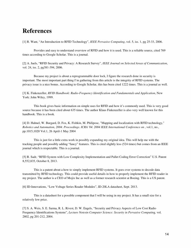
[1] R. Want, “An Introduction to RFID Technology”, IEEE Pervasive Computing, vol. 5, iss. 1, pg 25-33, 2006.
Provides and easy to understand overview of RFID and how it is used. This is a reliable source, cited 769
times according to Google Scholar. This is a journal.
[2] A. Juels, “RFID Security and Privacy: A Research Survey”, IEEE Journal on Selected Areas of Communication,
vol. 24, iss. 2, pg381-394, 2006.
Because my project is about a reprogrammable door lock, I figure the research done in security is
important. The most important part thing I’m gathering from this article is the integrity of RFID systems. The
privacy issue is a nice bonus. According to Google Scholar, this has been cited 1222 times. This is a journal as well.
[3] K. Finkenzeller, RFID Handbook: Radio-Frequency Identification and Fundamentals and Application, New
York: John Wiley, 1999.
This book gives basic information on simple uses for RFID and how it’s commonly used. This is very good
source because it has been cited about 635 times. The author Klaus Finkenzeller is also very well known for this
handbook. This is a book.
[4] D. Hahnel, W. Burgard, D. Fox, K. Fishkin, M. Philipose, "Mapping and localization with RFID technology,"
Robotics and Automation, 2004. Proceedings. ICRA '04. 2004 IEEE International Conference on , vol.1, no.,
pp.1015,1020 Vol.1, 26 April-1 May 2004
This is just for a little extra work in possibly expanding my original idea. This will help me with the
tracking people and possibly adding “fancy” features. This is cited slightly less (524 times) but comes from an IEEE
journal which is respectable. This is a journal.
[5] R. Sadr, “RFID System with Low Complexity Implementation and Pallet Coding Error Correction” U.S. Patent
8,552,835, October 8, 2013.
This is a patent about a how to simply implement RFID systems. It goes over systems to decode data
transmitted by RFID technology. This could provide useful details in how to properly implement the RFID reader in
my project. The author is a CEO of Mojix Inc as well as a former research scientist at Boeing. This is a US patent.
[6] ID-Innovations, “Low Voltage Series Reader Modules”, ID-20LA datasheet, Sept. 2013.
This is a datasheet for a possible component that I will be using in my project. It has a small size for a
relatively low price.
[7] S. A. Weis, S. E. Sarma, R. L. Rivest, D. W. Engels, “Security and Privacy Aspects of Low Cost Radio
Frequency Identifications Systems”, Lecture Notesin Computer Science: Security in Pervasive Computing, vol.
2802, pg 201-212, 2004.

15
This is another article about security and privacy of RFID technology except this applies more for my
project due to the low cost considerations. This is another strong source due to be cited a whopping 1367 times. The
author s are all very well-known researchers in their respective fields as well.
[8] S. A. Weis, “Security and Privacy in Radio-Frequency Identification Devices”, May 2003 [Online] Available:
http://www.iaetech.com.my/images/img/81939471.pdf
This is another source about security and privacy. This is credible because the author has written another
commonly cited source as well as being a professor at MIT.
[9] M. Gotanda, “Door Lock Control Systems” U.S. Patent 4,712,103, Dec. 8, 1987.
This is an interesting patent more on the mechanical side of the project. This patent is cited surprisingly
often for a simple door lock system (149 times).
[10] R. Martin, “Electronic Combination Door Lock with Dead Bolt Sensing Means”, U.S. Patent 4,148,092, Aug.
3,1979.
This is yet another patent on the door lock. This one is more of a sensing system that I could hopefully
adjust and tune for RFID systems.
[11] Cytron Technologies Sdn. Bhd., “RFID Door Lock”, Door Lock Datasheet, Jan. 2012
http://www.cytron.com.my/usr_attachment/PR25_DD.pdf
This was a very helpful datasheet that provided the basic building blocks of and construction of an RFID
door lock. Of course, several features differ heavily from this circuit.
[12] Atmel, “8-bit AVR Microcontroller with 4/8/16/32K Bytes In-System Programmable Flash”, Arduino
Datasheet, Nov. 2013 [Revised Oct. 2012] http://www.atmel.com/Images/doc8161.pdf
This datasheet is for the Arduino and provided all the necessary information needed to implement it as the
microcontroller for the system.
[13] Grant Gibson, “ How to get started with the Mifare MF522-AN and Arduino”, April 2012 [Online] Available:
http://www.grantgibson.co.uk/2012/04/how-to-get-started-with-the-mifare-mf522-an-and-arduino/
This information is what was used for finding the code to link the Arduino and the RFID chosen for this
project.
[14] Texas Instruments, “LMC662 CMOS Dual Operation Amplifier”, IC Datasheet, April 1998
http://www.ti.com/lit/ds/symlink/lmc662.pdf
[15] Fairchild Semiconductor, “3-Terminal Positive Adjustable Regulator”, IC Datasheet, July 2013
http://www.fairchildsemi.com/ds/LM/LM317.pdf

16
Appendix A - Senior Project Analysis
• 1. Summary of Functional Requirements
The RFID Door Lock is a simple door lock that can be attached to any normal door. It unlocks when the presence of
the RFID tag is nearby and locks when it is not detected. There is also a LED that lets the user know when the door
is locked and unlocked. It provides the security of a normal door lock without the hassle of keys.
• 2. Primary Constraints
The greatest constraint of this project is reliability and security. If this product is not reliable or secure, the product
has no purpose. Another constraint is the cost. The door lock’s cost should be low enough as to encourage
consumers to buy the product. Therefore, the majority of the design may involve software rather than buying actual
hardware components. This concern has priority over the cost.
This project became difficult with the the coding and the amplifying circuit. Since RFIDs are difficult to code,
source code from an online site was taken (Reference 13). This code did not include anything about adding an
output to the Arduino depending on whether a RFID tag was present, so finding this out was tricky. Once this was
figured out, the amplifying circuit was next.
The amplifying circuit’s problems included the ability to about the current necessary to power the electromagnetic
door lock while still keeping the voltage at it’s highest. In the end, a compromise was made by using a NPN
transistor as a current amplifier which dropped the voltage across the door lock. However, this current amplifier was
necessary as it is still at a voltage higher than it would have been with insufficient current.
• 3. Economic
The economic concerns in terms of Human Capital, Financial Capital, Manufactured Capital, and Natural Capital
are very small. As for Human Capital, the work lies in design and heavily in programming. The Financial Capital
involves the components such as resistors, microcontroller, LCD screens, etc. The Manufacture Capital involves the
printed PCB for the circuits designed. The Natural Capital is not almost nothing as the resources used are passive
components and a microcontroller.
The benefits should begin to outweigh the costs when the profit obtained exceeds the time of labor. This could be
anywhere from the first couple of sales to large sales depending on the time taken to complete the final product,
which should be approximately three months.
The inputs required by the RFID door lock are all from the user/owner as well as the RFID tag. The initial estimated
cost is $61.84 to acquire all the necessary components. However, the lab equipment needed are computers,
oscilloscopes, and a PCB manufacturer which can rack up the costs of this project. There is also the added cost of
labor, which is estimated to be around $100. The project should earn a fair amount if the price is low enough. The
consumers profit from satisfaction while I profit financially.
The actual cost of the project totalled to be $96.65.
The estimated development time from the Gantt chart is about 6-7 months. This, however, does not include the
design and development time.
The following Table 4 is an estimate of all the essential components required for the RFID door lock. The majority
of these were found through Amazon. It includes all the parts required for the actual door lock. Testing equipment
such as a breadboard, wires, screws and screwdrivers are not included in this cost. The total of the door lock can be
found at the bottom of Table 4.
17
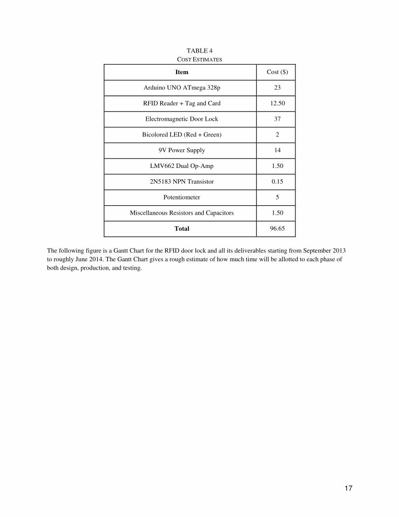
TABLE 4
COST ESTIMATES
Item Cost ($)
Arduino UNO ATmega 328p 23
RFID Reader + Tag and Card 12.50
Electromagnetic Door Lock 37
Bicolored LED (Red + Green) 2
9V Power Supply 14
LMV662 Dual Op-Amp 1.50
2N5183 NPN Transistor 0.15
Potentiometer 5
Miscellaneous Resistors and Capacitors 1.50
Total 96.65
The following figure is a Gantt Chart for the RFID door lock and all its deliverables starting from September 2013
to roughly June 2014. The Gantt Chart gives a rough estimate of how much time will be allotted to each phase of
both design, production, and testing.
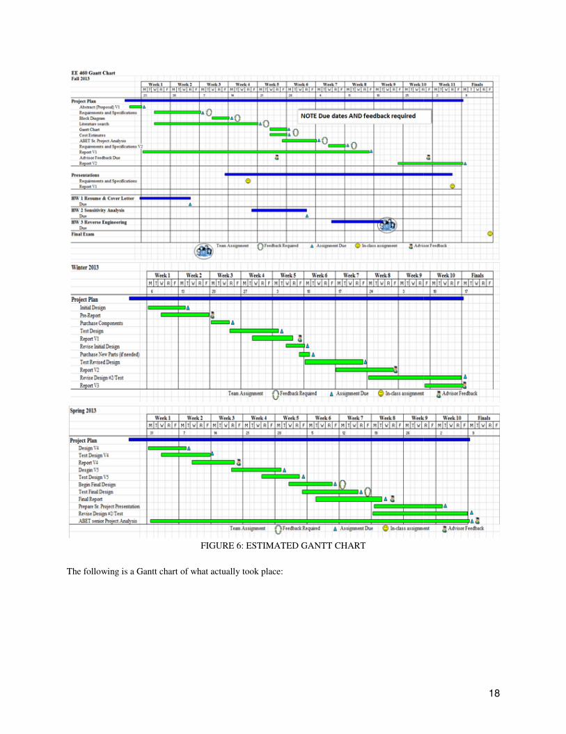
FIGURE 6: ESTIMATED GANTT CHART
The following is a Gantt chart of what actually took place:
FIGURE 6: ESTIMATED GANTT CHART
chart of what actually took place:
18
19
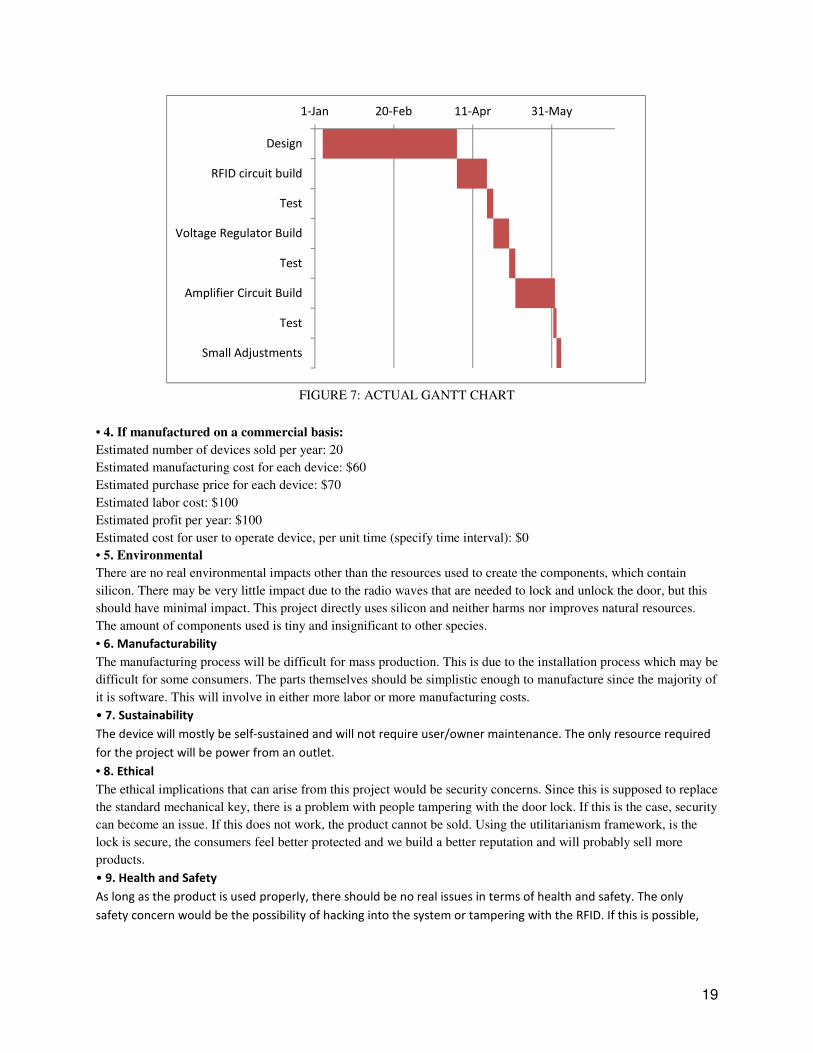
FIGURE 7: ACTUAL GANTT CHART
• 4. If manufactured on a commercial basis:
Estimated number of devices sold per year: 20
Estimated manufacturing cost for each device: $60
Estimated purchase price for each device: $70
Estimated labor cost: $100
Estimated profit per year: $100
Estimated cost for user to operate device, per unit time (specify time interval): $0
• 5. Environmental
There are no real environmental impacts other than the resources used to create the components, which contain
silicon. There may be very little impact due to the radio waves that are needed to lock and unlock the door, but this
should have minimal impact. This project directly uses silicon and neither harms nor improves natural resources.
The amount of components used is tiny and insignificant to other species.
• 6. Manufacturability
The manufacturing process will be difficult for mass production. This is due to the installation process which may be
difficult for some consumers. The parts themselves should be simplistic enough to manufacture since the majority of
it is software. This will involve in either more labor or more manufacturing costs.
• 7. Sustainability
The device will mostly be self-sustained and will not require user/owner maintenance. The only resource required
for the project will be power from an outlet.
• 8. Ethical
The ethical implications that can arise from this project would be security concerns. Since this is supposed to replace
the standard mechanical key, there is a problem with people tampering with the door lock. If this is the case, security
can become an issue. If this does not work, the product cannot be sold. Using the utilitarianism framework, is the
lock is secure, the consumers feel better protected and we build a better reputation and will probably sell more
products.
• 9. Health and Safety
As long as the product is used properly, there should be no real issues in terms of health and safety. The only
safety concern would be the possibility of hacking into the system or tampering with the RFID. If this is possible,
1-Jan 20-Feb 11-Apr 31-May
Design
RFID circuit build
Test
Voltage Regulator Build
Test
Amplifier Circuit Build
Test
Small Adjustments
20
the safety of the homeowners will be compromised. Fortunately, this system still allows for the consumer to use
the normal key for their locking mechanism and to disable any RFID key locks.
• 10. Social and Political
The design and manufacturing of this RFID door lock may increase the usage and creation of multiple chips and
transistors. This project impacts the consumers and they are the stakeholders. If the project is successful in what it
does, it will provide adequate security as well as a sense of safety in the stakeholder’s own home. However, this
project could harm the stakeholders if the device is not reliable or secure. Assuming the device is the same for all,
all stakeholders should have equal benefits.
• 11. Development
Important topics that require independent study are creating a secure electrical system that can’t be brute-forced,
creating the necessary RFID signals, and creating the software that will be used with the specific microprocessor. A
list of the sources used as research in all types of door locks can be found in the References section.
21
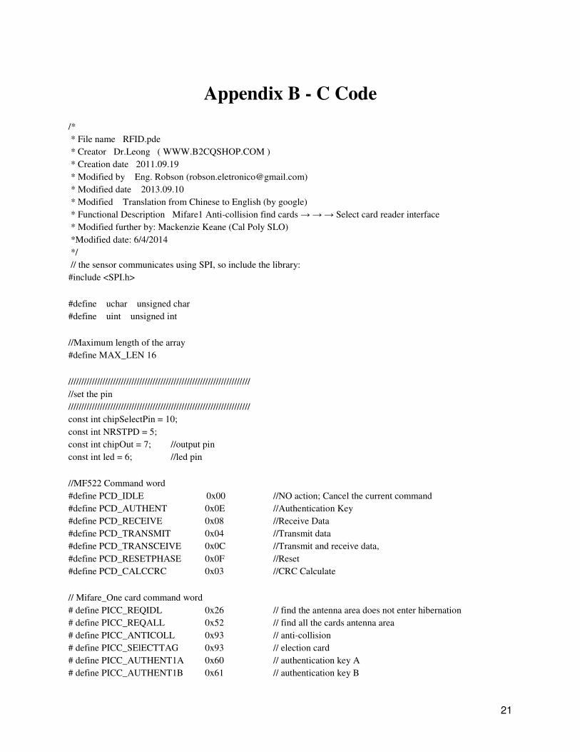
Appendix B - C Code
/*
* File name�RFID.pde
* Creator�Dr.Leong ( WWW.B2CQSHOP.COM )
* Creation date�2011.09.19
* Modified by� Eng. Robson ([email protected])
* Modified date� 2013.09.10
* Modified� Translation from Chinese to English (by google)
* Functional Description�Mifare1 Anti-collision find cards → → → Select card reader interface
* Modified further by: Mackenzie Keane (Cal Poly SLO)
*Modified date: 6/4/2014
*/
// the sensor communicates using SPI, so include the library:
#include <SPI.h>
#define uchar unsigned char
#define uint unsigned int
//Maximum length of the array
#define MAX_LEN 16
/////////////////////////////////////////////////////////////////////
//set the pin
/////////////////////////////////////////////////////////////////////
const int chipSelectPin = 10;
const int NRSTPD = 5;
const int chipOut = 7; //output pin
const int led = 6; //led pin
//MF522 Command word
#define PCD_IDLE 0x00 //NO action; Cancel the current command
#define PCD_AUTHENT 0x0E //Authentication Key
#define PCD_RECEIVE 0x08 //Receive Data
#define PCD_TRANSMIT 0x04 //Transmit data
#define PCD_TRANSCEIVE 0x0C //Transmit and receive data,
#define PCD_RESETPHASE 0x0F //Reset
#define PCD_CALCCRC 0x03 //CRC Calculate
// Mifare_One card command word
# define PICC_REQIDL 0x26 // find the antenna area does not enter hibernation
# define PICC_REQALL 0x52 // find all the cards antenna area
# define PICC_ANTICOLL 0x93 // anti-collision
# define PICC_SElECTTAG 0x93 // election card
# define PICC_AUTHENT1A 0x60 // authentication key A
# define PICC_AUTHENT1B 0x61 // authentication key B
22
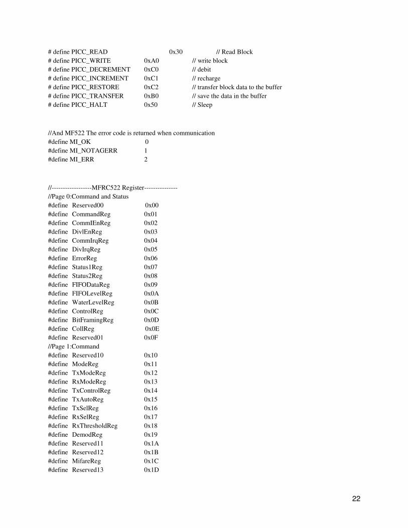
# define PICC_READ 0x30 // Read Block
# define PICC_WRITE 0xA0 // write block
# define PICC_DECREMENT 0xC0 // debit
# define PICC_INCREMENT 0xC1 // recharge
# define PICC_RESTORE 0xC2 // transfer block data to the buffer
# define PICC_TRANSFER 0xB0 // save the data in the buffer
# define PICC_HALT 0x50 // Sleep
//And MF522 The error code is returned when communication
#define MI_OK 0
#define MI_NOTAGERR 1
#define MI_ERR 2
//------------------MFRC522 Register---------------
//Page 0:Command and Status
#define Reserved00 0x00
#define CommandReg 0x01
#define CommIEnReg 0x02
#define DivlEnReg 0x03
#define CommIrqReg 0x04
#define DivIrqReg 0x05
#define ErrorReg 0x06
#define Status1Reg 0x07
#define Status2Reg 0x08
#define FIFODataReg 0x09
#define FIFOLevelReg 0x0A
#define WaterLevelReg 0x0B
#define ControlReg 0x0C
#define BitFramingReg 0x0D
#define CollReg 0x0E
#define Reserved01 0x0F
//Page 1:Command
#define Reserved10 0x10
#define ModeReg 0x11
#define TxModeReg 0x12
#define RxModeReg 0x13
#define TxControlReg 0x14
#define TxAutoReg 0x15
#define TxSelReg 0x16
#define RxSelReg 0x17
#define RxThresholdReg 0x18
#define DemodReg 0x19
#define Reserved11 0x1A
#define Reserved12 0x1B
#define MifareReg 0x1C
#define Reserved13 0x1D
23
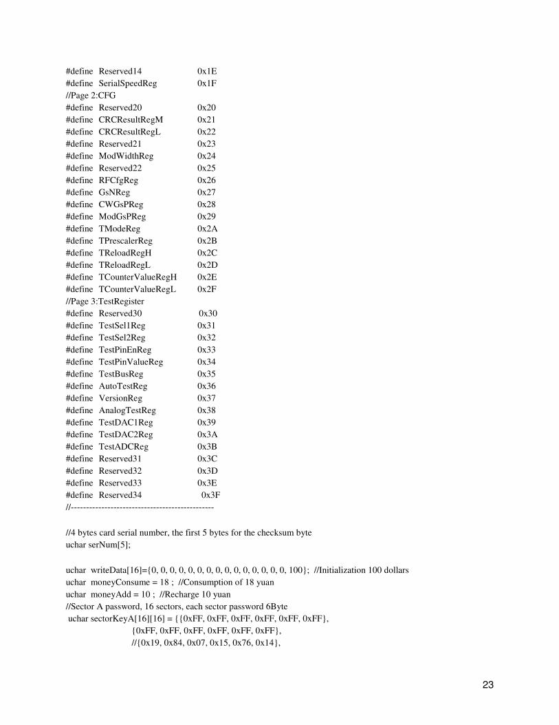
#define Reserved14 0x1E
#define SerialSpeedReg 0x1F
//Page 2:CFG
#define Reserved20 0x20
#define CRCResultRegM 0x21
#define CRCResultRegL 0x22
#define Reserved21 0x23
#define ModWidthReg 0x24
#define Reserved22 0x25
#define RFCfgReg 0x26
#define GsNReg 0x27
#define CWGsPReg 0x28
#define ModGsPReg 0x29
#define TModeReg 0x2A
#define TPrescalerReg 0x2B
#define TReloadRegH 0x2C
#define TReloadRegL 0x2D
#define TCounterValueRegH 0x2E
#define TCounterValueRegL 0x2F
//Page 3:TestRegister
#define Reserved30 0x30
#define TestSel1Reg 0x31
#define TestSel2Reg 0x32
#define TestPinEnReg 0x33
#define TestPinValueReg 0x34
#define TestBusReg 0x35
#define AutoTestReg 0x36
#define VersionReg 0x37
#define AnalogTestReg 0x38
#define TestDAC1Reg 0x39
#define TestDAC2Reg 0x3A
#define TestADCReg 0x3B
#define Reserved31 0x3C
#define Reserved32 0x3D
#define Reserved33 0x3E
#define Reserved34 0x3F
//-----------------------------------------------
//4 bytes card serial number, the first 5 bytes for the checksum byte
uchar serNum[5];
uchar writeData[16]={0, 0, 0, 0, 0, 0, 0, 0, 0, 0, 0, 0, 0, 0, 0, 100}; //Initialization 100 dollars
uchar moneyConsume = 18 ; //Consumption of 18 yuan
uchar moneyAdd = 10 ; //Recharge 10 yuan
//Sector A password, 16 sectors, each sector password 6Byte
uchar sectorKeyA[16][16] = {{0xFF, 0xFF, 0xFF, 0xFF, 0xFF, 0xFF},
{0xFF, 0xFF, 0xFF, 0xFF, 0xFF, 0xFF},
//{0x19, 0x84, 0x07, 0x15, 0x76, 0x14},
24
{0xFF, 0xFF, 0xFF, 0xFF, 0xFF, 0xFF},
};
uchar sectorNewKeyA[16][16] = {{0xFF, 0xFF, 0xFF, 0xFF, 0xFF, 0xFF},
{0xFF, 0xFF, 0xFF, 0xFF, 0xFF, 0xFF, 0xff,0x07,0x80,0x69, 0x19,0x84,0x07,0x15,0x76,0x14},
//you can set another ket , such as " 0x19, 0x84, 0x07, 0x15, 0x76, 0x14 "
//{0x19, 0x84, 0x07, 0x15, 0x76, 0x14, 0xff,0x07,0x80,0x69,
0x19,0x84,0x07,0x15,0x76,0x14},
// but when loop, please set the sectorKeyA, the same key, so that RFID module can read
the card
{0xFF, 0xFF, 0xFF, 0xFF, 0xFF, 0xFF, 0xff,0x07,0x80,0x69, 0x19,0x33,0x07,0x15,0x34,0x14},
};
void setup() {
Serial.begin(9600); // RFID reader SOUT pin connected to Serial RX pin at 2400bps
// start the SPI library:
SPI.begin();
pinMode(chipSelectPin,OUTPUT); // Set digital pin 10 as OUTPUT to connect it to the RFID /ENABLE
pin
digitalWrite(chipSelectPin, LOW); // Activate the RFID reader
pinMode(NRSTPD,OUTPUT); // Set digital pin 10 , Not Reset and Power-down
digitalWrite(NRSTPD, HIGH);
pinMode(chipOut, OUTPUT); //sets Pin 7 to an output
pinMode(led, OUTPUT); //sets the led as an output
MFRC522_Init();
}
void loop()
{
uchar i,tmp, checksum1;
uchar status;
uchar str[MAX_LEN];
uchar RC_size;
uchar blockAddr; //Selection operation block address 0 to 63
String mynum = "";
//Find cards, return card type
status = MFRC522_Request(PICC_REQIDL, str);
if (status == MI_OK)
{
digitalWrite(chipOut, HIGH); //sets pin 7 to low if the tag is reconized
digitalWrite(led, HIGH); //sets led to on when tag
delay(10000); //delays 10s for door to relock
//Serial.println("Card detected");
//Serial.print(str[0],BIN);
//Serial.print(" , ");
25
//Serial.print(str[1],BIN);
//Serial.println(" ");
}
else
{
digitalWrite(chipOut, LOW); //sets output to high voltage
digitalWrite(led, LOW); //turns led off
}
//Anti-collision, return card serial number 4 bytes
status = MFRC522_Anticoll(str);
memcpy(serNum, str, 5);
if (status == MI_OK)
{
checksum1 = serNum[0] ^ serNum[1] ^ serNum[2] ^ serNum[3];
//Serial.println("The card's number is : ");
Serial.print(2);
Serial.print(serNum[0]);
//Serial.print(" , ");
Serial.print(serNum[1],BIN);
//Serial.print(" , ");
Serial.print(serNum[2],BIN);
//Serial.print(" , ");
Serial.print(serNum[3],BIN);
//Serial.print(" , ");
Serial.print(serNum[4],BIN);
Serial.print(checksum1);
Serial.print(3);
//Serial.println(" ");
// Should really check all pairs, but for now we'll just use the first
if(serNum[0] == 88) {
Serial.println("Hello Grant");
} else if(serNum[0] == 173) {
Serial.println("Hello David");
}
delay(1000);
}
//Serial.println(" ");
MFRC522_Halt(); //Command card into hibernation
}
/*
* Function Name�Write_MFRC5200
* Function Description: To a certain MFRC522 register to write a byte of data
* Input Parameters�addr - register address; val - the value to be written
26
* Return value: None
*/
void Write_MFRC522(uchar addr, uchar val)
{
digitalWrite(chipSelectPin, LOW);
//Address Format�0XXXXXX0
SPI.transfer((addr<<1)&0x7E);
SPI.transfer(val);
digitalWrite(chipSelectPin, HIGH);
}
/*
* Function Name�Read_MFRC522
* Description: From a certain MFRC522 read a byte of data register
* Input Parameters: addr - register address
* Returns: a byte of data read from the
*/
uchar Read_MFRC522(uchar addr)
{
uchar val;
digitalWrite(chipSelectPin, LOW);
//Address Format�1XXXXXX0
SPI.transfer(((addr<<1)&0x7E) | 0x80);
val =SPI.transfer(0x00);
digitalWrite(chipSelectPin, HIGH);
return val;
}
/*
* Function Name�SetBitMask
* Description: Set RC522 register bit
* Input parameters: reg - register address; mask - set value
* Return value: None
*/
void SetBitMask(uchar reg, uchar mask)
{
uchar tmp;
tmp = Read_MFRC522(reg);
Write_MFRC522(reg, tmp | mask); // set bit mask
}
27
/*
* Function Name: ClearBitMask
* Description: clear RC522 register bit
* Input parameters: reg - register address; mask - clear bit value
* Return value: None
*/
void ClearBitMask(uchar reg, uchar mask)
{
uchar tmp;
tmp = Read_MFRC522(reg);
Write_MFRC522(reg, tmp & (~mask)); // clear bit mask
}
/*
* Function Name�AntennaOn
* Description: Open antennas, each time you start or shut down the natural barrier between the transmitter should
be at least 1ms interval
* Input: None
* Return value: None
*/
void AntennaOn(void)
{
uchar temp;
temp = Read_MFRC522(TxControlReg);
if (!(temp & 0x03))
{
SetBitMask(TxControlReg, 0x03);
}
}
/*
* Function Name: AntennaOff
* Description: Close antennas, each time you start or shut down the natural barrier between the transmitter should
be at least 1ms interval
* Input: None
* Return value: None
*/
void AntennaOff(void)
{
ClearBitMask(TxControlReg, 0x03);
}
/*
28
* Function Name: ResetMFRC522
* Description: Reset RC522
* Input: None
* Return value: None
*/
void MFRC522_Reset(void)
{
Write_MFRC522(CommandReg, PCD_RESETPHASE);
}
/*
* Function Name�InitMFRC522
* Description: Initialize RC522
* Input: None
* Return value: None
*/
void MFRC522_Init(void)
{
digitalWrite(NRSTPD,HIGH);
MFRC522_Reset();
//Timer: TPrescaler*TreloadVal/6.78MHz = 24ms
Write_MFRC522(TModeReg, 0x8D); //Tauto=1; f(Timer) = 6.78MHz/TPreScaler
Write_MFRC522(TPrescalerReg, 0x3E); //TModeReg[3..0] + TPrescalerReg
Write_MFRC522(TReloadRegL, 30);
Write_MFRC522(TReloadRegH, 0);
Write_MFRC522(TxAutoReg, 0x40); //100%ASK
Write_MFRC522(ModeReg, 0x3D); //CRC Initial value 0x6363 ???
//ClearBitMask(Status2Reg, 0x08); //MFCrypto1On=0
//Write_MFRC522(RxSelReg, 0x86); //RxWait = RxSelReg[5..0]
//Write_MFRC522(RFCfgReg, 0x7F); //RxGain = 48dB
AntennaOn(); //Open the antenna
}
/*
* Function Name�MFRC522_Request
* Description: Find cards, read the card type number
* Input parameters: reqMode - find cards way
* TagType - Return Card Type
* 0x4400 = Mifare_UltraLight
* 0x0400 = Mifare_One(S50)
* 0x0200 = Mifare_One(S70)
29
* 0x0800 = Mifare_Pro(X)
* 0x4403 = Mifare_DESFire
* Return value: the successful return MI_OK
*/
uchar MFRC522_Request(uchar reqMode, uchar *TagType)
{
uchar status;
uint backBits; //The received data bits
Write_MFRC522(BitFramingReg, 0x07); //TxLastBists = BitFramingReg[2..0] ???
TagType[0] = reqMode;
status = MFRC522_ToCard(PCD_TRANSCEIVE, TagType, 1, TagType, &backBits);
if ((status != MI_OK) || (backBits != 0x10))
{
status = MI_ERR;
}
return status;
}
/*
* Function Name: MFRC522_ToCard
* Description: RC522 and ISO14443 card communication
* Input Parameters: command - MF522 command word,
* sendData--RC522 sent to the card by the data
* sendLen--Length of data sent
* backData--Received the card returns data,
* backLen--Return data bit length
* Return value: the successful return MI_OK
*/
uchar MFRC522_ToCard(uchar command, uchar *sendData, uchar sendLen, uchar *backData, uint *backLen)
{
uchar status = MI_ERR;
uchar irqEn = 0x00;
uchar waitIRq = 0x00;
uchar lastBits;
uchar n;
uint i;
switch (command)
{
case PCD_AUTHENT: //Certification cards close
{
irqEn = 0x12;
waitIRq = 0x10;
30
break;
}
case PCD_TRANSCEIVE: //Transmit FIFO data
{
irqEn = 0x77;
waitIRq = 0x30;
break;
}
default:
break;
}
Write_MFRC522(CommIEnReg, irqEn|0x80); //Interrupt request
ClearBitMask(CommIrqReg, 0x80); //Clear all interrupt request bit
SetBitMask(FIFOLevelReg, 0x80); //FlushBuffer=1, FIFO Initialization
Write_MFRC522(CommandReg, PCD_IDLE); //NO action; Cancel the current command???
//Writing data to the FIFO
for (i=0; i<sendLen; i++)
{
Write_MFRC522(FIFODataReg, sendData[i]);
}
//Execute the command
Write_MFRC522(CommandReg, command);
if (command == PCD_TRANSCEIVE)
{
SetBitMask(BitFramingReg, 0x80); //StartSend=1,transmission of data starts
}
//Waiting to receive data to complete
i = 2000; //i according to the clock frequency adjustment, the operator M1 card maximum waiting time 25ms???
do
{
//CommIrqReg[7..0]
//Set1 TxIRq RxIRq IdleIRq HiAlerIRq LoAlertIRq ErrIRq TimerIRq
n = Read_MFRC522(CommIrqReg);
i--;
}
while ((i!=0) && !(n&0x01) && !(n&waitIRq));
ClearBitMask(BitFramingReg, 0x80); //StartSend=0
if (i != 0)
{
if(!(Read_MFRC522(ErrorReg) & 0x1B)) //BufferOvfl Collerr CRCErr ProtecolErr
{
31
status = MI_OK;
if (n & irqEn & 0x01)
{
status = MI_NOTAGERR; //??
}
if (command == PCD_TRANSCEIVE)
{
n = Read_MFRC522(FIFOLevelReg);
lastBits = Read_MFRC522(ControlReg) & 0x07;
if (lastBits)
{
*backLen = (n-1)*8 + lastBits;
}
else
{
*backLen = n*8;
}
if (n == 0)
{
n = 1;
}
if (n > MAX_LEN)
{
n = MAX_LEN;
}
//Reading the received data in FIFO
for (i=0; i<n; i++)
{
backData[i] = Read_MFRC522(FIFODataReg);
}
}
}
else
{
status = MI_ERR;
}
}
//SetBitMask(ControlReg,0x80); //timer stops
//Write_MFRC522(CommandReg, PCD_IDLE);
return status;
}
32
/*
* Function Name: MFRC522_Anticoll
* Description: Anti-collision detection, reading selected card serial number card
* Input parameters: serNum - returns 4 bytes card serial number, the first 5 bytes for the checksum byte
* Return value: the successful return MI_OK
*/
uchar MFRC522_Anticoll(uchar *serNum)
{
uchar status;
uchar i;
uchar serNumCheck=0;
uint unLen;
//ClearBitMask(Status2Reg, 0x08); //TempSensclear
//ClearBitMask(CollReg,0x80); //ValuesAfterColl
Write_MFRC522(BitFramingReg, 0x00); //TxLastBists = BitFramingReg[2..0]
serNum[0] = PICC_ANTICOLL;
serNum[1] = 0x20;
status = MFRC522_ToCard(PCD_TRANSCEIVE, serNum, 2, serNum, &unLen);
if (status == MI_OK)
{
//Check card serial number
for (i=0; i<4; i++)
{
serNumCheck ^= serNum[i];
}
if (serNumCheck != serNum[i])
{
status = MI_ERR;
}
}
//SetBitMask(CollReg, 0x80); //ValuesAfterColl=1
return status;
}
/*
* Function Name: CalulateCRC
* Description: CRC calculation with MF522
* Input parameters: pIndata - To read the CRC data, len - the data length, pOutData - CRC calculation results
* Return value: None
*/
33
void CalulateCRC(uchar *pIndata, uchar len, uchar *pOutData)
{
uchar i, n;
ClearBitMask(DivIrqReg, 0x04); //CRCIrq = 0
SetBitMask(FIFOLevelReg, 0x80); //Clear the FIFO pointer
//Write_MFRC522(CommandReg, PCD_IDLE);
//Writing data to the FIFO
for (i=0; i<len; i++)
{
Write_MFRC522(FIFODataReg, *(pIndata+i));
}
Write_MFRC522(CommandReg, PCD_CALCCRC);
//Wait CRC calculation is complete
i = 0xFF;
do
{
n = Read_MFRC522(DivIrqReg);
i--;
}
while ((i!=0) && !(n&0x04)); //CRCIrq = 1
//Read CRC calculation result
pOutData[0] = Read_MFRC522(CRCResultRegL);
pOutData[1] = Read_MFRC522(CRCResultRegM);
}
/*
* Function Name: MFRC522_SelectTag
* Description: election card, read the card memory capacity
* Input parameters: serNum - Incoming card serial number
* Return value: the successful return of card capacity
*/
uchar MFRC522_SelectTag(uchar *serNum)
{
uchar i;
uchar status;
uchar size;
uint recvBits;
uchar buffer[9];
//ClearBitMask(Status2Reg, 0x08); //MFCrypto1On=0
buffer[0] = PICC_SElECTTAG;
buffer[1] = 0x70;
34
for (i=0; i<5; i++)
{
buffer[i+2] = *(serNum+i);
}
CalulateCRC(buffer, 7, &buffer[7]); //??
status = MFRC522_ToCard(PCD_TRANSCEIVE, buffer, 9, buffer, &recvBits);
if ((status == MI_OK) && (recvBits == 0x18))
{
size = buffer[0];
}
else
{
size = 0;
}
return size;
}
/*
* Function Name: MFRC522_Auth
* Description: Verify card password
* Input parameters: authMode - Password Authentication Mode
0x60 = A key authentication
0x61 = Authentication Key B
BlockAddr--Block address
Sectorkey--Sector password
serNum--Card serial number, 4-byte
* Return value: the successful return MI_OK
*/
uchar MFRC522_Auth(uchar authMode, uchar BlockAddr, uchar *Sectorkey, uchar *serNum)
{
uchar status;
uint recvBits;
uchar i;
uchar buff[12];
//Verify the command block address + sector + password + card serial number
buff[0] = authMode;
buff[1] = BlockAddr;
for (i=0; i<6; i++)
{
buff[i+2] = *(Sectorkey+i);
}
for (i=0; i<4; i++)
{
buff[i+8] = *(serNum+i);
35
}
status = MFRC522_ToCard(PCD_AUTHENT, buff, 12, buff, &recvBits);
if ((status != MI_OK) || (!(Read_MFRC522(Status2Reg) & 0x08)))
{
status = MI_ERR;
}
return status;
}
/*
* Function Name: MFRC522_Read
* Description: Read block data
* Input parameters: blockAddr - block address; recvData - read block data
* Return value: the successful return MI_OK
*/
uchar MFRC522_Read(uchar blockAddr, uchar *recvData)
{
uchar status;
uint unLen;
recvData[0] = PICC_READ;
recvData[1] = blockAddr;
CalulateCRC(recvData,2, &recvData[2]);
status = MFRC522_ToCard(PCD_TRANSCEIVE, recvData, 4, recvData, &unLen);
if ((status != MI_OK) || (unLen != 0x90))
{
status = MI_ERR;
}
return status;
}
/*
* Function Name: MFRC522_Write
* Description: Write block data
* Input parameters: blockAddr - block address; writeData - to 16-byte data block write
* Return value: the successful return MI_OK
*/
uchar MFRC522_Write(uchar blockAddr, uchar *writeData)
{
uchar status;
uint recvBits;
uchar i;

36
uchar buff[18];
buff[0] = PICC_WRITE;
buff[1] = blockAddr;
CalulateCRC(buff, 2, &buff[2]);
status = MFRC522_ToCard(PCD_TRANSCEIVE, buff, 4, buff, &recvBits);
if ((status != MI_OK) || (recvBits != 4) || ((buff[0] & 0x0F) != 0x0A))
{
status = MI_ERR;
}
if (status == MI_OK)
{
for (i=0; i<16; i++) //Data to the FIFO write 16Byte
{
buff[i] = *(writeData+i);
}
CalulateCRC(buff, 16, &buff[16]);
status = MFRC522_ToCard(PCD_TRANSCEIVE, buff, 18, buff, &recvBits);
if ((status != MI_OK) || (recvBits != 4) || ((buff[0] & 0x0F) != 0x0A))
{
status = MI_ERR;
}
}
return status;
}
/*
* Function Name: MFRC522_Halt
* Description: Command card into hibernation
* Input: None
* Return value: None
*/
void MFRC522_Halt(void)
{
uchar status;
uint unLen;
uchar buff[4];
buff[0] = PICC_HALT;
buff[1] = 0;
CalulateCRC(buff, 2, &buff[2]);
status = MFRC522_ToCard(PCD_TRANSCEIVE, buff, 4, buff,&unLen);
37
}
/*
* Function Name: MFRC522_Output
* Description: allows for the correct output depending on if the tag is reconized
* Input parameters:
* Return value: None
*/
void MFRC522_Output(void)
{
if(!MI_OK)
digitalWrite(chipOut, HIGH); //sets pin 7 to low if the tag is reconized
else
digitalWrite(chipOut, LOW); //sets pin 7 to high if no tag
}