rexroth precision ball screw assemblies end … precision ball screw assemblies end bearings and nut...
TRANSCRIPT

Rexroth Precision Ball Screw AssembliesEnd Bearings andNut Housings
The Drive & Control Company
RE 83 301/2002-09

RE 83 301/2002-09 2
Rexroth – Precision Ball Screw Assemblies
Ball Rail Systems Standard Rail Systems
Rail Systems with Aluminium Runner Blocks
Super Rail Systems
Wide Rail Systems
Supplementary Parts
Miniature Rail Systems
Cam Roller Guides
Roller Rail Systems
Linear Bushings and Shafts Linear Bushings
Linear Sets
Shafts
Shaft Support Rails
Shaft Support Blocks
Ball Transfer Units
Other Engineering Components
Precision Ball Screw Ball Screw Assemblies
Assemblies Drive Assemblies
Linear Modules
Compact Modules
+ Ball Screw+ Toothed Belt
+ Ball Screw+ Toothed Belt+ Gear Rack+ Linear Motor+ Pneumatic Drive
+ Ball Screw
+ Ball Screw+ Linear Motor
Linear Motion Systems Linear Motion Slides
Ball Rail Tables
Controllers, Motors, Electrical Accessories
Electric Cylinders
Rexroth – Linear Motion Technology

3 RE 83 301/2002-09
Rexroth – Precision Ball Screw Assemblies
Product Overview 4
Application Examples 14
Inquiries and Orders 16
Dimension Tables 22– Nuts 22
– Nut Housings 46
– Screws 50
– End Machining Details 54
– Pillow Block Units 78
– Bearings 86
– Slotted Nuts and Housing Nuts 92
Technical Notes 94
Acceptance Conditions and Tolerance Grades 96
Preload and Rigidity 100
Friction Torques of Seals 106
Mounting 108
Lubrication 110
Design Calculations 114
End Bearings, Design Notes, Mounting Instructions 118
End Bearings, Design Calculations 120
Design Calculation Service Form 122
Inquiry / Order Form 123
RE 83 301/2002-09 4
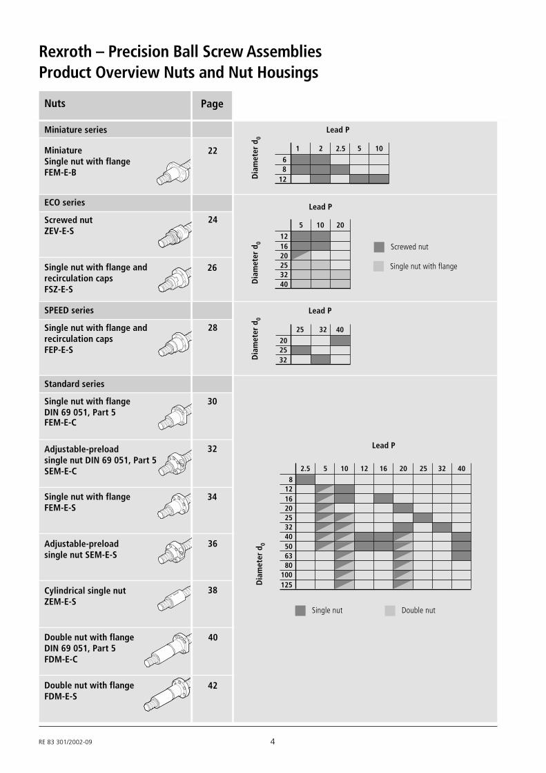
Rexroth – Precision Ball Screw AssembliesProduct Overview Nuts and Nut Housings
PageNuts
22
24
26
Miniature series
ECO series
Single nut with flange andrecirculation capsFSZ-E-S
Single nut with flange andrecirculation capsFEP-E-S
Screwed nutZEV-E-S
28
MiniatureSingle nut with flangeFEM-E-B
SPEED series
1
68
12
2 1052.5
121620253240
5 10 20
Lead P
Dia
met
er d
0
2.5
8121620253240506380
100125
5 10 12 16 20 25 32 40
Single nut Double nut
Standard series
30
32
34
36
38
Single nut with flangeDIN 69 051, Part 5
Single nut with flangeFEM-E-S
Adjustable-preloadsingle nut SEM-E-S
Cylindrical single nutZEM-E-S
Double nut with flangeDIN 69 051, Part 5FDM-E-C
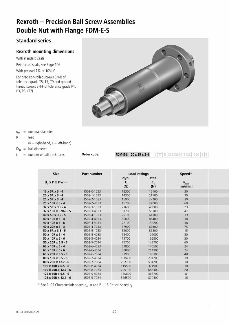
Double nut with flangeFDM-E-S
40
42
Adjustable-preloadsingle nut DIN 69 051, Part 5SEM-E-C
Lead P
Dia
met
er d
0
Screwed nut
Single nut with flangeD
iam
eter
d0
Lead P
Dia
met
er d
0
Lead P
25
202532
32 40
FEM-E-C

5 RE 83 301/2002-09
PageNuts
Driven nut
48
44Driven nut FAR-B-S
MGSfor Standard series
FEM-E-SFDM-E-SSEM-E-S
46
Nut housings
MGDfor Standard series
FEM-E-CFDM-E-CSEM-E-C
2.5
1620253240506380
5 10 12 16 20 25 32 40
Lead P
Dia
met
er d
0
MGS
MGD
32405063
10 20 32 40
Lead P
Dia
met
er d
0

RE 83 301/2002-09 6
Rexroth – Precision Ball Screw Assemblies
Page
Product Overview Screws and End Machining
Ground thread screw SN-FTolerance gradesP1, P3, P5, (T7)
Acceptance conditions
Precision-rolled screw SN-RTolerance gradesT5, T7, T9,(P5)
Screws
standard, available at shortnotice
availableupon request
Maximum length
(mm)
Acceptance conditions
Screw end machining
96
1500 2500 7500
8 x 2.5
16 x 5, 10, 16
25 x 5, 10, 2532 x 5, 10, 20, 3240 x 5 / 50 x 5
50 x 10, 12, 16, 20, 4063 x 10, 20, 4080 x 10
4500 5000
d0 x P
40 x 10, 12, 16, 20, 40
6x1 / 6x2 / 8x1 / 8x2
12 x 2, 5, 10
20 x 5, 20, 40
available upon request
96
52
54
1500 3000 80005000
d0 x P
10001200
16 x 5, 10, 1620 x 5, 2025 x 5, 10, 2532 x 5, 10, 20, 32
40 x 10, 12, 16, 20, 4050 x 10, 12, 16, 20, 4063 x 10, 20, 4080 x 10, 20
100 x 10, 20125 x 10, 20
12 x 5, 108 x 2.5
40 x 5 / 50 x 5
800 4000
standard, available at shortnotice
available uponrequest
Maximum length
(mm)
Lead P
Dia
met
er d
0
2.5
8121620253240506380
5 10 12 16 20 25 32 40
6
21
7 RE 83 301/2002-09
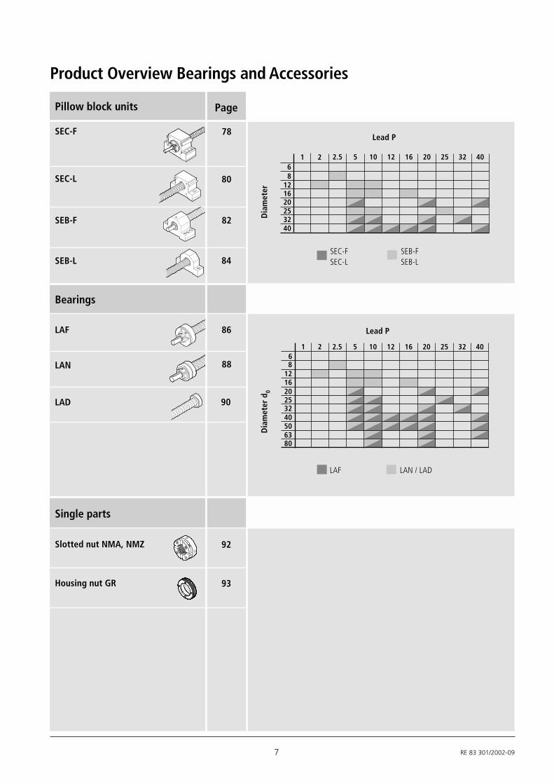
Slotted nut NMA, NMZ
Housing nut GR
Single parts
Product Overview Bearings and Accessories
Lead P
Dia
met
er d
0
LAF LAN / LAD
SEC-F
Pillow block units
SEC-L
SEB-F
SEB-L
Lead P
Dia
met
er
SEC-FSEC-L
SEB-FSEB-L
2.5
8121620253240
5 10 12 16 20 25 32 401 26
2.5
8121620253240506380
5 10 12 16 20 25 32 406
1 2
78
80
82
84
Bearings
LAF
LAN
LAD
86
88
90
92
93
Page

RE 83 301/2002-09 8
Rexroth – Precision Ball Screw AssembliesProduct OverviewDefinition of a precision ball screwassembly
DIN 69 051 Part 1 defines a ballscrew as follows:
An assembly comprising a ball screwshaft and a ball nut and which iscapable of converting rotary motioninto linear motion and vice versa.
The rolling elements of the assemblyare balls.
As simple as it is to describe theelementary function of a precisionball screw assembly, in practice youare faced with variety of types andapplications.
New nut series have increased thesize of the catalog. The catalog nowfeatures additional miniature sizes,double-square leads and a series forECO applications. There is now also aseries of driven nuts available.
The single and double nuts from theprevious catalog are now called theStandard series for identification purposes.As before, the nuts with flanges from theStandard series are available in versionswith both Rexroth and DIN mountingdimensions. The related standards(DIN 69 051 and ISO 3408) are thereforefully supported by Rexroth.
The new series are tailor-made for specificapplications or instances of use:
– Miniature series: extends the range tocover smaller sizes
– ECO series: the low-cost solutionthrough to the medium size range inthe form of screwed nut (ECO) or singlenut with flange (ECOplus)
– Speed series: maximum linear speedswith simultaneous high load rating andshort nut length
– Driven nuts:for maximum dynamics with longstrokes or for specific instances ofinstallation
Precision-rolled screws in a variety ofsizes and of unequaled quality have longbeen an essential part of our product range.Our comprehensive, worldwide stocksguarantee fast response times in everylocation. Availability is one advantage, lowprices another. Every nut featured in thiscatalog can be combined with theprecision-rolled screws. The only excepti-ons are nut sizes ≥ 80x20. For theseapplications and other specific instances ofuse we manufacture screws to individualcustomer requirements by means ofgrinding.
To perform particularly demandingpositioning tasks we have developed theIntegrated Measuring System for Ball Railand Roller Rail systems (Catalog RE 82350). The linear measuring system in therail then replaces the positioning informa-tion in the ball screw. This way we areable to achieve a maximum of flexibility indesign and a maximum of precision inoperation.
Rexroth Precision Ball ScrewAssemblies provide technical designerswith diverse solutions for positioning andtransport tasks:
– complete ball screw assemblies withdriven screws or now also driven nuts
– complete ball screw assemblies withsingle or double nuts, combined withground thread screws of various sizes
– precision-rolled screws of optionallength with soft-annealed ends andground-thread screws in "fixeddimension lengths" for end machiningby the customer
– single nuts supplied on a mountingarbor; almost all single nuts in theversion with reduced backlash can beeasily mounted by the customer. Inaddition, the adjustable-preload singlenut of the Standard series allows thecustomer to perform preloadadjustment in-house.
– matching nut housings and endbearings for the Standard series
For applications with heavy-duty ball screwassemblies, please ask for our specialbrochures.
For a further system solution, please referto our catalog Rexroth DriveAssemblies (Catalog RE 83 304). Inaddition to the ball screw assembly, youcan select here a flange/coupling or sidedrive with timing belt with AC servomotorand control system:
– Drive assemblies with driven screw;alternatively also with protectivehousing and screw support
– Drive assemblies with driven nut: thedriven nut either with side drive withtiming belt or in conjunction with ahollow-shaft motor
9 RE 83 301/2002-09
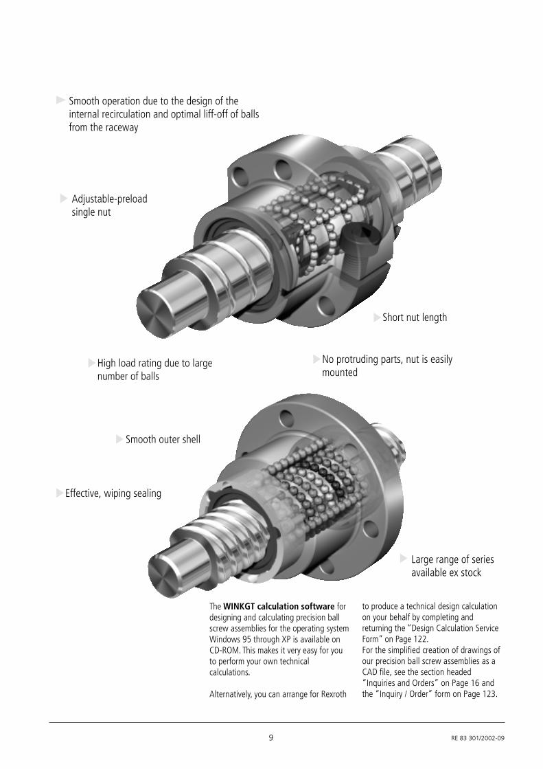
The WINKGT calculation software fordesigning and calculating precision ballscrew assemblies for the operating systemWindows 95 through XP is available onCD-ROM. This makes it very easy for youto perform your own technicalcalculations.
Alternatively, you can arrange for Rexroth
Effective, wiping sealing
No protruding parts, nut is easilymounted
High load rating due to largenumber of balls
Smooth outer shell
to produce a technical design calculationon your behalf by completing andreturning the “Design Calculation ServiceForm” on Page 122.For the simplified creation of drawings ofour precision ball screw assemblies as aCAD file, see the section headed“Inquiries and Orders” on Page 16 andthe “Inquiry / Order” form on Page 123.
Smooth operation due to the design of theinternal recirculation and optimal liff-off of ballsfrom the raceway
Large range of seriesavailable ex stock
Short nut length
Adjustable-preloadsingle nut
RE 83 301/2002-09 10
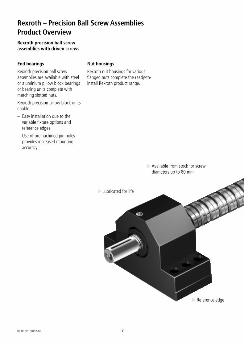
Rexroth – Precision Ball Screw AssembliesProduct OverviewRexroth precision ball screwassemblies with driven screws
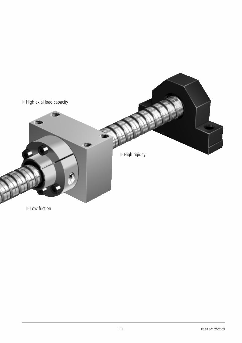
End bearings
Rexroth precision ball screwassemblies are available with steelor aluminium pillow block bearingsor bearing units complete withmatching slotted nuts.
Rexroth precision pillow block unitsenable:
– Easy installation due to thevariable fixture options andreference edges
– Use of premachined pin holesprovides increased mountingaccuracy
Nut housings
Rexroth nut housings for variousflanged nuts complete the ready-to-install Rexroth product range.
Available from stock for screwdiameters up to 80 mm
Lubricated for life
Reference edge
11 RE 83 301/2002-09
High rigidity
High axial load capacity
Low friction
RE 83 301/2002-09 12
Rexroth – Precision Ball Screw Assemblies
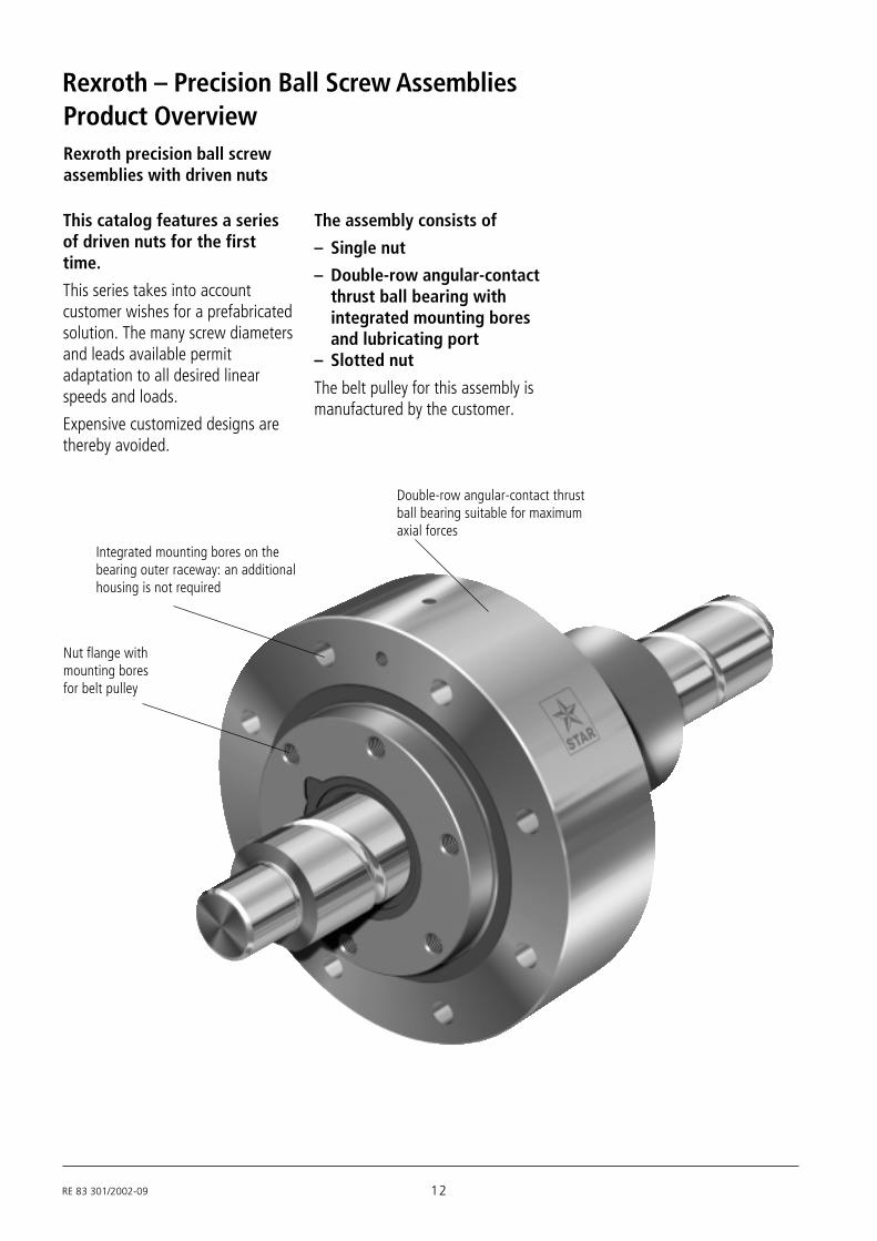
This catalog features a seriesof driven nuts for the firsttime.
This series takes into accountcustomer wishes for a prefabricatedsolution. The many screw diametersand leads available permitadaptation to all desired linearspeeds and loads.
Expensive customized designs arethereby avoided.
Rexroth precision ball screwassemblies with driven nuts
Product Overview
The assembly consists of
– Single nut
– Double-row angular-contactthrust ball bearing withintegrated mounting boresand lubricating port
– Slotted nut
The belt pulley for this assembly ismanufactured by the customer.
Integrated mounting bores on thebearing outer raceway: an additionalhousing is not required
Nut flange withmounting boresfor belt pulley
Double-row angular-contact thrustball bearing suitable for maximumaxial forces
13 RE 83 301/2002-09
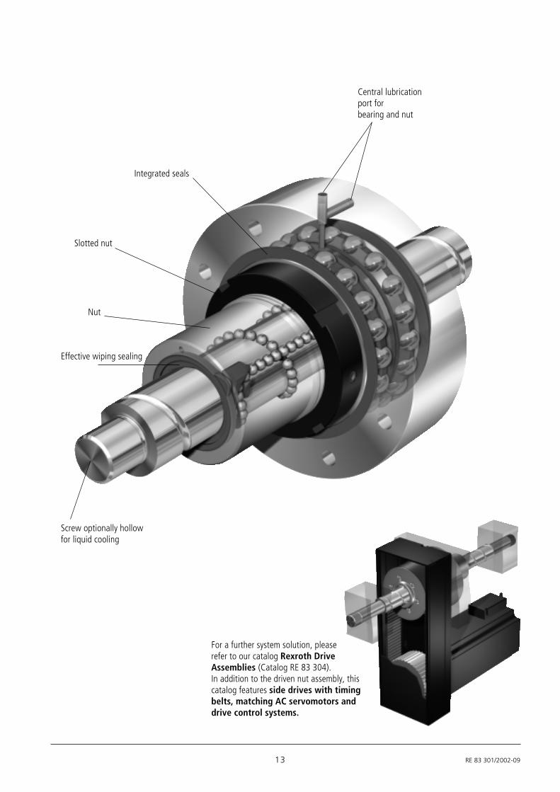
For a further system solution, pleaserefer to our catalog Rexroth DriveAssemblies (Catalog RE 83 304).In addition to the driven nut assembly, thiscatalog features side drives with timingbelts, matching AC servomotors anddrive control systems.
Screw optionally hollowfor liquid cooling
Nut
Slotted nut
Integrated seals
Central lubricationport forbearing and nut
Effective wiping sealing

RE 83 301/2002-09 14
Rexroth – Precision Ball Screw Assemblies
Machining center
Vertical axis with driven nut
Application Examples
– Cutting machine tools– Forming machine tools– Automation and handling– Woodworking– Electrical and electronics– Printing and paper– Injection molding machines– Food and packaging industry– Medical equipment– Textile industry– etc.
Rexroth Precision Ball ScrewAssemblies have beensuccessfully implementedworldwide in the followingareas:

15 RE 83 301/2002-09
Lathe
Folding press

RE 83 301/2002-09 16
Rexroth – Precision Ball Screw Assemblies
Nominal diameters, leads
Overall length Lov
Overall length Lov of a precision ball screw assembly
Inquiries and Orders
All nuts, screws and end machining detailscan now be defined with the order code.
We have taken account of all formerselection criteria as well as adding newones. The diversity of possiblecombinations is limitless.
Attention is focused in particular on thedefinition of end machining details. Formany design versions there is a prepareddefinition, providing you with a suitablesolution for practically every application.
If you wish to send us an inquiry, simplycomplete the form on Page 122 of thiscatalog.
If no drawing is available, please specifyyour wishes using the variable order code.You will find a summary of the options onPage 19.
Should you already have a drawingavailable as a CAD file (in Pro/E20,AutoCAD/Genius 14 or DXF formats), youcan send us the data by e-mail (see theback cover of the catalog for our e-mailaddress).
If the drawing exists on paper only, youcan, of course, send it to us byconventional mail.
Each customer-specific precision ball screwassembly is issued with an ID numberwhen an order is placed. If you have anysubsequent queries, you need only quotethis ID number.
2.5
8121620253240506380
5 10 12 16 20 25 32 40
Lead P
Nom
inal
dia
met
er d
0
Screws > dia. 80 mm available on request

17 RE 83 301/2002-09
Nut typeThe various series versions and forms are shown below.
Z E M - E - SCylindrical single nut
Standard series
F E M - E - CSingle nut with flange
DIN 69 051, Part 5, Standardseries
FDM-E-C Double nut with flangeDIN 69 051, Part 5
Standard series
SEM-E-C Adjustable-preloadsingle nut , DIN 69 051 Part 5,
Standard series
FEM-E-SSingle nut with flange
Standard series
SEM-E-S Adjustable-preloadsingle nut
Standard series
F D M - E - SDouble nut with flange
Standard series
Mounting direction of nut typesDefinition: The centering diameter on a nut with flange, theslotted nut on a driven nut and the lube bore on a cylindrical nutpoints to the right end of the screw.
Centering diameter D1
Centering diameter D1
Lube port
Page 30
Page 34
Page 32
Page 36
Page 38
Page 40 Page 42
FEM-E-B Single nut with flangeMiniature series
Page 22
ZEV-E-S Screwed nutECO series
Page 24
FEP-E-S Single nut with flangeSpeed series
Page 28
FAR-B-SDriven nut
FSZ-E-S Single nut with flangeECO series
Page 26
Lube port
Slotted nut
Page 44
Driven nut
RE 83 301/2002-09 18
Rexroth – Precision Ball Screw Assemblies
00
01
11
21
31
41
51
61
71
81
91
02
12
62
72
82
92
53
83
93
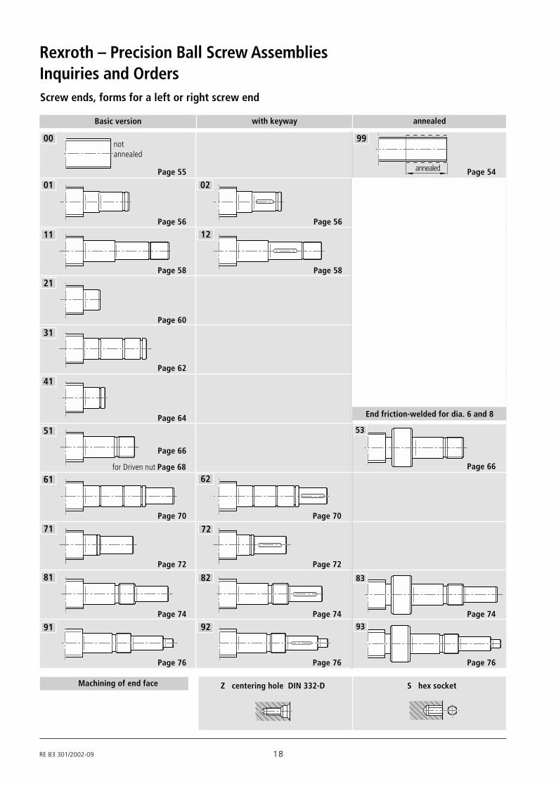
Screw ends, forms for a left or right screw end
Basic version with keyway annealed
Page 55
Page 56
Page 58
Page 60
Page 62
Page 64
Page 66
Page 70
Page 72
Page 74
Page 76
Page 70
Page 72
Page 74
Page 76
Page 66
Page 74
Page 76
Page 56
Page 58
Machining of end face Z centering hole DIN 332-D S hex socket
End friction-welded for dia. 6 and 8
annealed Page 54
99
Inquiries and Orders
00
01
11
21
31
41
51
61
71
81
91
02
12
62
72
82
92
99
53
83
93
notannealed
for Driven nut Page 68

19 RE 83 301/2002-09
Precision Ball Screw Assembly
Nut typeFEM-E-B Single nut with flange Miniature seriesZEV-E-S Screwed nut ECO seriesFSZ-E-S Single nut with flange ECO seriesFEP-E-S Single nut with flange Speed seriesFEM-E-C Single nut with flange to DIN 69 051, Part 5FEM-E-S Single nut with flange, Rexroth mount. dimensionsSEM-E-C Adjustable-preload single nut to DIN 69 051, Part 5SEM-E-S Adjustable-preload single nut Rexroth mount. dim.ZEM-E-S Cylindrical single nut, Rexroth mount. dimensionsFDM-E-C Double nut with flange to DIN 69 051, Part 5FDM-E-S Double nut with flange, Rexroth mount. dimensions
FAR-B-S Driven nut
Screw
0 … none 2*… reinforced seal
1 … standard seal X … not possible
0 … standard backlash 4 … 10% (double nut)1 … reduced backlash 5 … 7% (double nut)
2**… 5% (single nut) X … not possible
3 … 2% (single nut) standard
(P5) T5 T7 T9 . ...precision-rolled screw
P1 P3 P5 (T7) .... ground-thread screw
R … precision-rolled F... ground-thread
SEM-E-S 20 x 5R x 3-4 1 2 T7 R 81Z120 41Z120 1250 1 1 SN 20 x 5R x 3 X X T7 R 81Z120 41Z120 1250 1 0
Right screw end
Overall length Lov (mm)
0 … standard (acceptance test report) 2 … torque test report-is always supplied 3 … lead and torque test report
1 … lead test report
0 … Preserved 1 … Preserved and nut with basic grease
Seal
Preload
Precision
Screw
Documentation
Lubrication
see left screw end
Left screw end
Size Nominal diameter (mm)Lead (mm)Direction of lead R … right, L … leftBall diameter (mm)Number of ball track turns in the nut
N.B.: It is also possible to process inquiries based on a customer’s drawings.
* only for d0 25 to 40 of the precision-rolled version; note higher frictional torque!
** only for d0 16 to 63
Order Code
FormZ … centering to DIN 332-D
Option S … hex socketK …none
Version

RE 83 301/2002-09 20
Rexroth – Precision Ball Screw Assemblies
Precision-rolled screwSN-R with annealed ends
For machining of screw ends by thecustomer.
SN 20 x 5R x 3 X X T7 R 99 K150 99K080 1250 1 0ScrewSize
PrecisionScrew: R…rolled
Right screw end see left screw endOverall length (mm)Documentation: 0, 1 … see page 15
Lubrication: 0 … preserved
Left screw end FormOption K…noneAnnealed length (mm)
Inquiries and Orders – Special Cases
Screw
150 annealed 80 annealed1250 overall length

21 RE 83 301/2002-09
150 annealed
80 annealed andmachine-faced
to core diameter
FEM-E-S 20 x 5R x 3-4 1 2 T7 R 99 K150 99K080 1250 1 1
Ball screw withprecision-rolled screwSN-R and annealed endsFor machining of screw ends by thecustomer.
Nut with preloadThe nut is delivered already mounted. Amounting tube is supplied for dismantling.
Nut without preloadThe nut and screw are deliveredunassembled.
Nut typeSize
PreloadPrecision
Seal
Left screw end FormOption K…noneAnnealed length (mm)
Right screw end see left screw endOverall length (mm)Documentation: 0, 1, 2, 3 … see page 15
Lubrication: 0 … preserved 1 … preserved and nut with basic grease
Screw: R…rolled
1250 overall length
Precision Ball Screw Assembly
Mounting direction
N.B.: The centering diameter (or lube port on a cylindrical nut) points to the ma-chine-faced, right-hand end of the screw. The shorter screw end is machine-faced to core diameter for mounting reasons.
Centering diameter D1

RE 83 301/2002-09 22
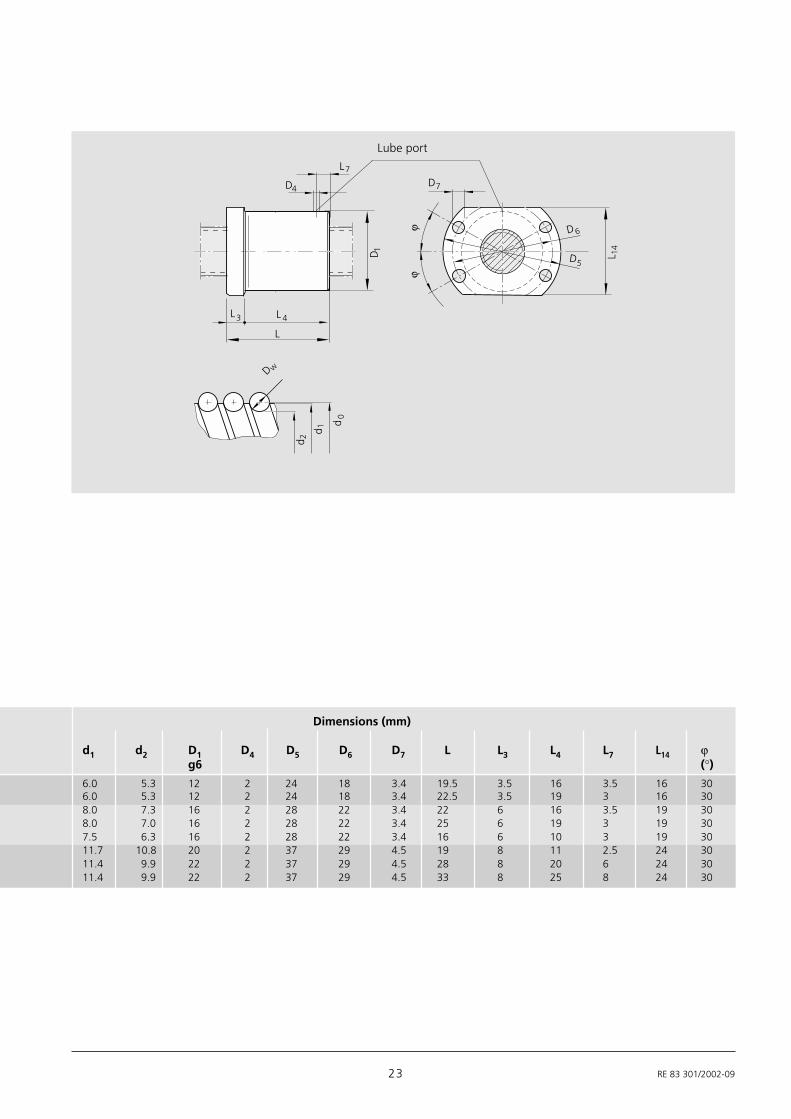
Rexroth – Precision Ball Screw AssembliesMiniature Single Nut with Flange FEM-E-B
d0 = nominal diameter
P = lead
(R = right-hand, L = left-hand)
DW = ball diameter
i = number of ball track turns
Rexroth mounting dimensions
Flange type BWith seals
With or without axial backlash
For precision-rolled screws SN-Rof tolerance grade 3, 5, 7
Miniature series
FEM-E-B 6 x 2R x 0.8 - 4 1 1 T7 R 83K060 41K050 250 0 1Order code:
Size Part number Load ratings Speed*dyn. stat.
d0 x P x Dw - i C C0 vmax
(N) (N) [m/min]
6 x 1 R x 0.8 - 4 1532-1-0006 900 1290 36 x 2 R x 0.8 - 4 1532-1-2006 890 1280 68 x 1 R x 0.8 - 4 1532-2-0006 1020 1740 38 x 2 R x 1.2 - 4 1532-2-2006 1870 2760 68 x 2.5 R x 1.588 - 3 1532-2-3006 2200 2800 1512 x 2 R x 1.2 - 4 1532-4-2006 2240 4160 1212 x 5 R x 2 - 3 1532-4-6006 3800 5800 3012 x 10 R x 2 - 2 1532-4-9006 2500 3600 60
* See P. 95 Characteristic speed d0 . n and P. 116 Critical speed nk
23 RE 83 301/2002-09
L 4
L
L3
D7
D6
D 1 L 14
Dw
d0
d 1
d 2
ϕ
D5
ϕ
L7
D4
Lube port
Dimensions (mm)
d1 d2 D1 D4 D5 D6 D7 L L3 L4 L7 L14 ϕg6 (°)
6.0 5.3 12 2 24 18 3.4 19.5 3.5 16 3.5 16 306.0 5.3 12 2 24 18 3.4 22.5 3.5 19 3 16 308.0 7.3 16 2 28 22 3.4 22 6 16 3.5 19 308.0 7.0 16 2 28 22 3.4 25 6 19 3 19 307.5 6.3 16 2 28 22 3.4 16 6 10 3 19 3011.7 10.8 20 2 37 29 4.5 19 8 11 2.5 24 3011.4 9.9 22 2 37 29 4.5 28 8 20 6 24 3011.4 9.9 22 2 37 29 4.5 33 8 25 8 24 30

RE 83 301/2002-09 24
Rexroth – Precision Ball Screw Assemblies
ECO series
d0 = nominal diameter
P = lead
(R = right-hand, L = left-hand)
DW = ball diameter
i = number of ball track turns
Rexroth mounting dimensionsWithout seals (no initial greasing)
Seals available on request
With backlash
For precision-rolled screws SN-Rof tolerance grade T7, T9
Size Part number Load ratings Speed*dyn. stat.
d0 x P x Dw - i C C0 vmax
(N) (N) [m/min]12 x 5R x 2 - 3 1532-4-6025 2300 3500 3012 x 10R x 2 - 2 1532-4-9025 1500 2200 6016 x 5R x 3 - 3 1512-0-1025 5600 7100 2516 x 10R x 3 - 3 1512-0-4025 5800 7400 5020 x 5R x 3 - 4 1512-1-1025 8600 12900 20
Screwed Nut ZEV-E-S
ZEV-E-S 20 x 5R x 3-4 0 0 T7 R 81K120 41K120 550 0 1Order code:
* See P. 95 Characteristic speed d0 . n and P. 116 Critical speed nk

25 RE 83 301/2002-09
L 15
L
D1
Dw
d 0d 1d 2
1G
L 7
D4D8
Dimensions (mm) Backlash (mm)
d1 d2 D1 D4 D8 G1 L L7 L15 maxh10 ±0.3
11.4 9.9 25.5 2.7 3.2 M20 x 1 36 8.5 10 0.111.4 9.9 25.5 2.7 3.2 M20 x 1 40 8.5 10 0.115.0 12.9 32.5 2.7 4.2 M26 x 1.5 40 10.5 12 0.115.0 12.9 32.5 2.7 4.2 M26 x 1.5 54 10.5 12 0.119.0 16.9 38 2.7 8 M35 x 1.5 50 12.5 14 0.1
Lube port
Bore for assembly wrench
RE 83 301/2002-09 26
Rexroth – Precision Ball Screw Assemblies
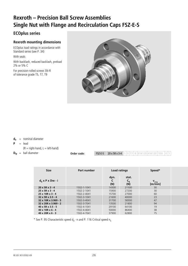
Rexroth mounting dimensionsECOplus load ratings in accordance withStandard series (see P. 34)
With seals
With backlash, reduced backlash, preload2% or 5% C
For precision-rolled screws SN-Rof tolerance grade T5, T7, T9
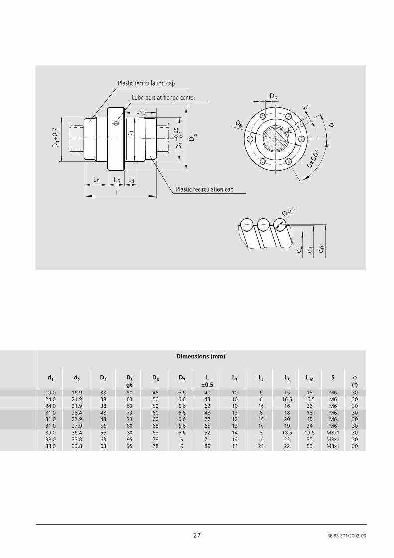
Single Nut with Flange and Recirculation Caps FSZ-E-S
d0 = nominal diameter
P = lead
(R = right-hand, L = left-hand)
DW = ball diameter
Size Part number Load ratings Speed*
dyn. stat.d0 x P x Dw - i C C0 vmax
(N) (N) [m/min]20 x 5R x 3 - 4 1502-1-1041 14300 21500 3025 x 5R x 3 - 4 1502-2-1041 15900 27200 3025 x 10R x 3 - 4 1502-2-4041 15700 27000 6032 x 5R x 3.5 - 4 1502-3-1041 21600 40000 2332 x 10R x 3.969 - 5 1502-3-4041 31700 58300 4732 x 20R x 3.969 - 2 1502-3-7041 13500 21800 9440 x 5R x 3.5 - 5 1502-4-1041 29100 64100 1940 x 10R x 6 - 4 1502-4-4041 50000 86400 3840 x 20R x 6 - 3 1502-4-7041 37900 62800 75
FSZ-E-S 20 x 5R x 3-4 1 0 T7 R 81K120 41K120 550 0 1Order code:
ECOplus series
* See P. 95 Characteristic speed d0 . n and P. 116 Critical speed nk
27 RE 83 301/2002-09
6x60
°
D6
L5 L4L3
L
D1
D1
Dw
d 0d 1d 2
SD7
+0.
7ϕ
L10
5D
D
–0.0
51
–0
.1
Dimensions (mm)
d1 d2 D1 D5 D6 D7 L L3 L4 L5 L10 S ϕg6 ±0.5 (°)
19.0 16.9 33 58 45 6.6 40 10 6 15 15 M6 3024.0 21.9 38 63 50 6.6 43 10 6 16.5 16.5 M6 3024.0 21.9 38 63 50 6.6 62 10 16 16 36 M6 3031.0 28.4 48 73 60 6.6 48 12 6 18 18 M6 3031.0 27.9 48 73 60 6.6 77 12 16 20 45 M6 3031.0 27.9 56 80 68 6.6 65 12 10 19 34 M6 3039.0 36.4 56 80 68 6.6 52 14 8 18.5 19.5 M8x1 3038.0 33.8 63 95 78 9 71 14 16 22 35 M8x1 3038.0 33.8 63 95 78 9 89 14 25 22 53 M8x1 30
Plastic recirculation cap
Plastic recirculation cap
Lube port at flange center

RE 83 301/2002-09 28
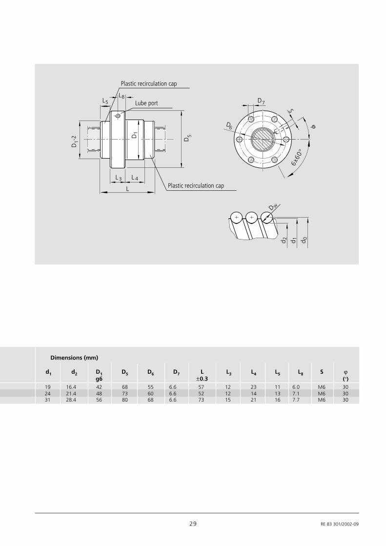
Rexroth – Precision Ball Screw AssembliesSingle Nut with Flange and Recirculation Caps FEP-E-S
Rexroth mounting dimensionsWith seals
With backlash, reduced backlash orpreload 2% C
For precision-rolled screws SN-R(quadruple) of tolerance grade T5, T7, T9
20 x 40R x 3.5 - 1 x 4 2522-100-11 8000 14900 15025 x 25R x 3.5 - 1.2 x 4 2522-200-01 19700 39400 12032 x 32R x 3.969 - 1.2 x 4 2522-300-01 26300 57600 120
d0 = nominal diameter
P = lead
(R = right-hand, L = left-hand)
DW = ball diameter
i = a x b
"a" Bearing turns per thread
"b" Number of bearing threads on thescrew
Speed series
Size Part number Load ratings Speed*dyn. stat.
d0 x P x Dw - i C C0 vmax
(N) (N) [m/min]
FEP-E-S 25 x 25R x 3.5-1.2x4 1 0 T5 R 81K170 41K120 1000 0 1Order code:
* See P. 95 Characteristic speed d0 . n and P. 116 Critical speed nk
29 RE 83 301/2002-09
19 16.4 42 68 55 6.6 57 12 23 11 6.0 M6 3024 21.4 48 73 60 6.6 52 12 14 13 7.1 M6 3031 28.4 56 80 68 6.6 73 15 21 16 7.7 M6 30
6x60
°
D6
L5
L 4L3
L
D1
D1
Dw
d 0d 1d 2
SD7
D5-2
ϕ
L8
Plastic recirculation cap
Plastic recirculation cap
Lube port
Dimensions (mm)
d1 d2 D1 D5 D6 D7 L L3 L4 L5 L8 S ϕg6 ±0.3 (°)

RE 83 301/2002-09 30
Rexroth – Precision Ball Screw AssembliesSingle Nut with Flange FEM-E-C
Mounting dimensions toDIN 69 051, Part 5
Flange type CWith standard seals
Reinforced seals, see Page 106
With backlash, reduced backlash,preload 2% or 5% C
For precision-rolled screws SN-R oftolerance grade T5, T7, T9 and ground-thread screws SN-F of tolerance grade P1,P3, P5, (T7)
d0 = nominal diameter
P = lead
(R = right-hand, L = left-hand)
DW = ball diameter
i = number of ball track turns
Size Part number Load ratings Speed*dyn. stat.
d0 x P x Dw - i C C0 vmax
(N) (N) [m/min]
16 x 5R x 3 - 4 1502-0-1065 12300 16100 3016 x 10R x 3 - 3 1502-0-4085 9600 12300 6016 x 16R x 3 - 3 1502-0-6065 9300 12000 9620 x 5R x 3 - 4 1502-1-1085 14300 21500 3020 x 20R x 3.5 - 3 1502-1-7065 13300 18800 12025 x 5R x 3 - 4 1502-2-1085 15900 27200 3025 x 10R x 3 - 4 1502-2-4085 15700 27000 6025 x 25R x 3.5 - 3 1502-2-8065 14700 23300 15032 x 5R x 3.5 - 4 1502-3-1085 21600 40000 2332 x 10R x 3.969 - 5 1502-3-4086 31700 58300 4732 x 20R x 3.969 - 3 1502-3-7065 19700 33700 9432 x 32R x 3.969 - 3 1502-3-9065 19500 34000 15040 x 5R x 3.5 - 5 1502-4-1086 29100 64100 1940 x 10R x 6 - 4 1502-4-4085 50000 86400 3840 x 12R x 6 - 4 1502-4-5065 49900 86200 4540 x 16R x 6 - 4 1502-4-6065 49700 85900 6040 x 20R x 6 - 3 1502-4-7085 37900 62800 7540 x 40R x 6 - 3 1502-4-9065 37000 62300 15050 x 5R x 3.5 - 5 1502-5-1086 32000 81300 1550 x 10R x 6 - 6 1502-5-4086 79700 166500 3050 x 12R x 6 - 6 1502-5-5066 79600 166400 3650 x 16R x 6 - 6 1502-5-6066 79400 166000 4850 x 20R x 6.5 - 5 1502-5-7086 75700 149700 6050 x 40R x 6.5 - 3 1502-5-9065 46500 85900 12063 x 10R x 6 - 6 1502-6-4086 88800 214300 2463 x 20R x 6.5 - 5 1502-6-7086 83900 190300 4863 x 40R x 6.5 - 3 1502-6-9065 53400 114100 9580 x 10R x 6.5 - 6 1502-7-4086 108400 291700 1980 x 20R x 12.7 - 6 1502-7-7096 262700 534200 30100 x 10R x 6.5 - 6 1502-8-4066 119500 371900 10100 x 20R x 12.7 - 6 1502-8-7066 295100 686400 20125 x 10R x 6.5 - 6 1502-9-4066 130600 468700 8125 x 20R x 12.7 - 6 1502-9-7066 326500 870400 16
FEM-E-C 20 x 5R x 3-4 1 2 T7 R 82Z120 41Z120 1250 1 0Order code:
Standard series
* See P. 95 Characteristic speed d0 . n and P. 116 Critical speed nk

31 RE 83 301/2002-09
90°
L 4
L
L 3
22.5°
90°
30°
30°
D7
D7
SS
D6
D6
D 1D5
L 9L 9
Dw
d 0d 1
d 2
L 10
-0.0
5-0
.1D
1
d0 ≤ 32
d0 ≥ 40
N.B.: On a ground-thread screw SN-F the corediameter d2 can be smaller by max. 0.3 mmdue to the manufacture.
Lube port at flange center
BB2
BB1
Dimensions (mm) Weight
d1 d2 D1 D5 Hole D6 D7 L L3 L4 L9 L10 S mg6 pattern (kg)
15.0 12.9 28 48 BB2 38 5.5 38 12 10 44.0 26 M6 0.1915.0 12.9 28 48 BB2 38 5.5 45 12 16 44.0 33 M6 0.2115.0 12.9 28 48 BB2 38 5.5 61 12 20 44.0 49 M6 0.2619.0 16.9 36 58 BB2 47 6.6 40 12 10 51.0 28 M6 0.3119.3 16.7 36 58 BB2 47 6.6 77 12 25 51.0 65 M6 0.4924.0 21.9 40 62 BB2 51 6.6 45 12 10 55.0 33 M6 0.3624.0 21.9 40 62 BB2 51 6.6 64 12 20 55.0 52 M6 0.4724.0 21.4 40 62 BB2 51 6.6 95 12 30 55.0 83 M6 0.6331.0 28.4 50 80 BB2 65 9.0 48 13 10 71.0 35 M6 0.6231.0 27.9 50 80 BB2 65 9.0 77 13 16 71.0 64 M6 0.8431.0 27.9 50 80 BB2 65 9.0 84 13 25 71.0 71 M6 0.9031.0 27.9 50 80 BB2 65 9.0 120 13 40 71.0 107 M6 1.2139.0 36.4 63 93 BB1 78 9.0 54 15 10 81.5 39 M8x1 1.0338.0 33.8 63 93 BB1 78 9.0 70 15 16 81.5 55 M8x1 1.1938.0 33.8 63 93 BB1 78 9.0 75 15 25 81.5 60 M8x1 1.2738.0 33.8 63 93 BB1 78 9.0 90 15 25 81.5 75 M8x1 1.5138.0 33.8 63 93 BB1 78 9.0 88 15 25 81.5 73 M8x1 1.4438.0 33.8 63 93 BB1 78 9.0 142 15 45 81.5 127 M8x1 2.1649.0 46.4 75 110 BB1 93 11.0 54 15 10 97.5 39 M8x1 1.3948.0 43.8 75 110 BB1 93 11.0 90 18 16 97.5 72 M8x1 2.1448.0 43.8 75 110 BB1 93 11.0 105 18 25 97.5 87 M8x1 2.3848.0 43.8 75 110 BB1 93 11.0 128 18 25 97.5 110 M8x1 2.7548.0 43.4 75 110 BB1 93 11.0 132 18 25 97.5 114 M8x1 2.7348.0 43.4 75 110 BB1 93 11.0 149 18 45 97.5 131 M8x1 3.0461.0 56.8 90 125 BB1 108 11.0 90 22 16 110.0 68 M8x1 2.5661.0 56.4 95 135 BB1 115 13.5 132 22 25 117.5 110 M8x1 4.5161.0 56.4 95 135 BB1 115 13.5 149 22 45 117.5 127 M8x1 5.0478.0 73.3 105 145 BB1 125 13.5 95 22 16 127.5 73 M8x1 3.4076.0 67.0 125 165 BB1 145 13.5 170 25 25 147.5 145 M8x1 10.2098.0 93.4 125 165 BB1 145 13.5 95 25 16 147.5 70 M8x1 4.4096.0 87.1 150 202 BB1 176 17.5 170 30 25 178.5 140 M8x1 14.30
123.0 118.0 150 202 BB1 176 17.5 95 25 16 178.5 70 M8x1 5.65121.0 112.0 170 222 BB1 196 17.5 170 40 25 198.5 130 M8x1 16.10

RE 83 301/2002-09 32
Rexroth – Precision Ball Screw Assemblies
Mounting dimensions toDIN 69 051, Part 5
Flange type CWith standard seals
Reinforced seals, see Page 106
Adjustable preload
For precision-rolled screws SN-R oftolerance grade T5, T7, T9 and ground-thread screws SN-F of tolerance grade P1,P3, P5, (T7)
Adjustable-Preload Single Nut SEM-E-C
d0 = nominal diameter
P = lead
(R = right-hand, L = left-hand)
DW = ball diameter
i = number of ball track turns
Size Part number Load ratings Speed*dyn. stat.
d0 x P x Dw - i C C0 vmax
(N) (N) [m/min]16 x 5R x 3 - 4 1512-0-1055 12300 16100 3016 x 10R x 3 - 3 1512-0-4075 9600 12300 6016 x 16R x 3 - 3 1512-0-6055 9300 12000 9620 x 5R x 3 - 4 1512-1-1075 14300 21500 3020 x 20R x 3.5 - 3 1512-1-7055 13300 18800 12025 x 5R x 3 - 4 1512-2-1075 15900 27200 3025 x 10R x 3 - 4 1512-2-4075 15700 27000 6025 x 25R x 3.5 - 3 1512-2-8055 14700 23300 15032 x 5R x 3.5 - 4 1512-3-1075 21600 40000 2332 x 10R x 3.969 - 5 1512-3-4075 31700 58300 4732 x 20R x 3.969 - 3 1512-3-7055 19700 33700 9432 x 32R x 3.969 - 3 1512-3-9055 19500 34000 15040 x 5R x 3.5 - 5 1512-4-1075 29100 64100 1940 x 10R x 6 - 4 1512-4-4075 50000 86400 3840 x 12R x 6 - 4 1512-4-5055 49900 86200 4540 x 20R x 6 - 3 1512-4-7075 37900 62800 7540 x 40R x 6 - 3 1512-4-9055 37000 62300 15050 x 5R x 3.5 - 5 1512-5-1075 32000 81300 1550 x 10R x 6 - 6 1512-5-4075 79700 166500 3050 x 12R x 6 - 6 1512-5-5055 79600 166400 3650 x 20R x 6.5 - 5 1512-5-7076 75700 149700 6050 x 40R x 6.5 - 3 1512-5-9055 46500 85900 12063 x 10R x 6 - 6 1512-6-4075 88800 214300 2463 x 20R x 6.5 - 5 1512-6-7076 83900 190300 4863 x 40R x 6.5 - 3 1512-6-9055 53400 114100 9580 x 10R x 6.5 - 6 1512-7-4075 108400 291700 1980 x 20R x 12.7 - 6 1512-7-7056 262700 534200 30
SEM-E-C 20 x 5R x 3-4 1 2 T7 R 82Z120 41Z120 1250 1 0Order code:
Standard series
* s.S. 95 Characteristic speed d0 . n and P. 116 Critical Speed nk

33 RE 83 301/2002-09
d0 ≤ 32
d0 ≥ 40
BB2
BB1
15.0 12.9 28 48 BB2 38 5.5 38 15 10 11.5 7.1 44 11.5 M6 0.2015.0 12.9 28 48 BB2 38 5.5 45 15 15 15 11 44 15 M6 0.2215.0 12.9 28 48 BB2 38 5.5 61 15 20 23 10 44 23 M6 0.2919.0 16.9 36 58 BB2 47 6.6 40 15 10 12.5 7.1 51 12.5 M6 0.3319.3 16.7 36 58 BB2 47 6.6 77 20 25 28.5 12.5 51 28.5 M6 0.5624.0 21.9 40 62 BB2 51 6.6 45 20 10 12.5 9.5 55 12.5 M6 0.4324.0 21.9 40 62 BB2 51 6.6 64 20 16 22 10 55 22 M6 0.5424.0 21.4 40 62 BB2 51 6.6 95 25 30 35 14 55 35 M6 0.7731.0 28.4 50 80 BB2 65 9 48 20 10 14 9.7 71 14 M6 0.7431.0 27.9 50 80 BB2 65 9 77 20 16 28.5 12.5 71 28.5 M6 0.9731.0 27.9 50 80 BB2 65 9 84 20 25 32 12.5 71 32 M6 1.0431.0 27.9 50 80 BB2 65 9 120 20 40 50 12.5 71 50 M6 1.3439.0 36.4 63 93 BB1 78 9 54 25 10 14.5 12 81.5 14.5 M8x1 1.2538.0 33.8 63 93 BB1 78 9 70 25 16 22.5 11.8 81.5 22.5 M8x1 1.3938.0 33.8 63 93 BB1 78 9 75 25 25 25 12.5 81.5 25 M8x1 1.4738.0 33.8 63 93 BB1 78 9 88 25 25 31.5 16.5 81.5 31.5 M8x1 1.5538.0 33.8 63 93 BB1 78 9 142 40 45 51 25 81.5 51 M8x1 2.6949.0 46.4 75 110 BB1 93 11 54 25 10 14.5 12 97.5 14.5 M8x1 1.6748.0 43.8 75 110 BB1 93 11 90 30 16 30 14.1 97.5 30 M8x1 2.4648.0 43.8 75 110 BB1 93 11 105 30 25 37.5 15 97.5 37.5 M8x1 2.6948.0 43.4 75 110 BB1 93 11 132 30 25 51 20 97.5 51 M8x1 3.0848.0 43.4 75 110 BB1 93 11 149 30 45 59.5 18 97.5 59.5 M8x1 3.3961.0 56.8 90 125 BB1 108 11 90 30 16 30 14 110 30 M8x1 2.8361.0 56.4 95 135 BB1 115 13.5 132 30 25 51 20 117.5 51 M8x1 4.86
L 10
L 3 L4
L
90°
22.5°30°
30°
90°
L 8
S
D6
D6
S
D7
D7
1D
1D
+0.
7
D5
L9
L9
L 5
D 1-0
.05
-0.1
Dw
d 0
d 1d 2
N.B.: On a ground-thread screw SN-F the corediameter d2 can be smaller by max. 0.3 mmdue to the manufacture.
Lube port
Dimensions (mm) Weight
d1 d2 D1 D5 Hole D6 D7 L L3 L4 L5 L8 L9 L10 S mf9 pattern (kg)

RE 83 301/2002-09 34
Rexroth – Precision Ball Screw Assemblies
Rexroth mounting dimensionsWith standard seals
Reinforced seals, see Page 106
With backlash, reduced backlash, preload2% or 5% C
For precision-rolled screws SN-R oftolerance grade T5, T7, T9 and ground-thread screws SN-F of tolerance grade P1,P3, P5, (T7)
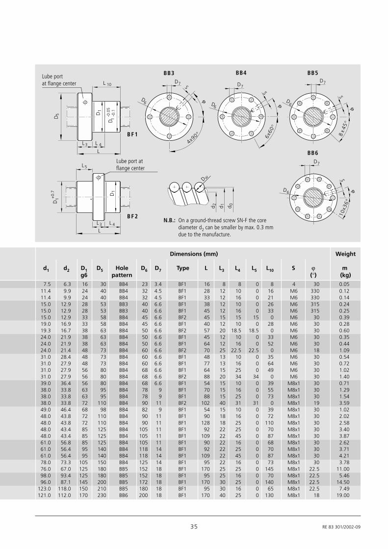
Single Nut with Flange FEM-E-S
d0 = nominal diameter
P = lead
(R = right-hand, L = left-hand)
DW = ball diameter
i = number of ball track turns
Size Part number Load ratings Speed*dyn. stat.
d0 x P x DW - i C C0 vmax
(N) (N) [m/min]8 x 2.5R x 1.588 - 3 1532-2-3003 2200 2800 1512 x 5R x 2 - 3 1532-4-6023 3800 5800 3012 x 10R x 2 - 2 1532-4-9013 2500 3600 6016 x 5R x 3 - 4 1512-0-1023 12300 16100 3016 x 10R x 3 - 3 1512-0-4013 9600 12300 6016 x 16R x 3 - 2 1512-0-6013 6300 7600 9620 x 5R x 3 - 4 1512-1-1013 14300 21500 3020 x 20R x 3.5 - 2 1512-1-7013 9100 12100 12025 x 5R x 3 - 4 1512-2-1013 15900 27200 3025 x 10R x 3 - 4 1512-2-4013 15700 27000 6025 x 25R x 3.5 - 2 1512-2-8013 10100 15100 15032 x 5R x 3.5 - 4 1512-3-1013 21600 40000 2332 x 10R x 3.969 - 5 1512-3-4013 31700 58300 4732 x 20R x 3.969 - 2 1512-3-7013 13500 21800 9432 x 32R x 3.969 - 2 1512-3-9013 13400 22000 15040 x 5R x 3.5 - 5 1512-4-1013 29100 64100 1940 x 10R x 6 - 4 1512-4-4013 50000 86400 3840 x 20R x 6 - 3 1512-4-7013 37900 62800 7540 x 40R x 6 - 2 1512-4-9013 25500 40300 15050 x 5R x 3.5 - 5 1512-5-1013 32000 81300 1550 x 10R x 6 - 6 1512-5-4013 79700 166500 3050 x 16R x 6 - 6 1512-5-6013 79400 166000 4850 x 20R x 6.5 - 3 1512-5-7013 47900 87900 6050 x 40R x 6.5 - 2 1512-5-9013 32100 55800 12063 x 10R x 6 - 6 1512-6-4013 88800 214300 2463 x 20R x 6.5 - 3 1512-6-7013 53200 112100 4863 x 40R x 6.5 - 2 1512-6-9013 36900 74300 9580 x 10R x 6.5 - 6 1512-7-4013 108400 291700 1980 x 20R x 12.7 - 6 1512-7-7023 262700 534200 30100 x 10R x 6.5 - 6 1502-8-4002 119500 371900 10100 x 20R x 12.7 - 6 1502-8-7002 295100 686400 20125 x 10R x 6.5 - 6 1502-9-4002 130600 468700 8125 x 20R x 12.7 - 6 1502-9-7002 326500 870400 16
FEM-E-S 20 x 5R x 3-4 1 2 T7 R 82Z120 41Z120 1250 1 0Order code:
Standard series
* See P. 95 Characteristic speed d0 . n and P. 116 Critical speed nk
35 RE 83 301/2002-09
S
6x60
°
D6
L 4L3
L
L5
L 4L3
L
4x90°
ϕ
S
D1
D5
D1+
0.7
D1
D 1-0
.05
-0.1
L 10
Dw
d 0d 1d 2
S
D7
D6
D7
D6
8x
45°
D7
D6
10x3
6°
D7
S
ϕ ϕϕ
Lube portat flange center
Lube port atflange center
BB3 BB4 BB5
BB6
B F 1
B F 2
Dimensions (mm) Weight
d1 d2 D1 D5 Hole D6 D7 Type L L3 L4 L5 L10 S ϕ mg6 pattern (°) (kg)
7.5 6.3 16 30 BB4 23 3.4 BF1 16 8 8 0 8 4 30 0.0511.4 9.9 24 40 BB4 32 4.5 BF1 28 12 10 0 16 M6 330 0.1211.4 9.9 24 40 BB4 32 4.5 BF1 33 12 16 0 21 M6 330 0.1415.0 12.9 28 53 BB3 40 6.6 BF1 38 12 10 0 26 M6 315 0.2415.0 12.9 28 53 BB3 40 6.6 BF1 45 12 16 0 33 M6 315 0.2515.0 12.9 33 58 BB4 45 6.6 BF2 45 15 15 15 0 M6 30 0.3919.0 16.9 33 58 BB4 45 6.6 BF1 40 12 10 0 28 M6 30 0.2819.3 16.7 38 63 BB4 50 6.6 BF2 57 20 18.5 18.5 0 M6 30 0.6024.0 21.9 38 63 BB4 50 6.6 BF1 45 12 10 0 33 M6 30 0.3524.0 21.9 38 63 BB4 50 6.6 BF1 64 12 16 0 52 M6 30 0.4424.0 21.4 48 73 BB4 60 6.6 BF2 70 25 22.5 22.5 0 M6 18 1.0931.0 28.4 48 73 BB4 60 6.6 BF1 48 13 10 0 35 M6 30 0.5431.0 27.9 48 73 BB4 60 6.6 BF1 77 13 16 0 64 M6 30 0.7231.0 27.9 56 80 BB4 68 6.6 BF1 64 15 25 0 49 M6 30 1.0231.0 27.9 56 80 BB4 68 6.6 BF2 88 20 34 34 0 M6 30 1.4039.0 36.4 56 80 BB4 68 6.6 BF1 54 15 10 0 39 M8x1 30 0.7138.0 33.8 63 95 BB4 78 9 BF1 70 15 16 0 55 M8x1 30 1.2938.0 33.8 63 95 BB4 78 9 BF1 88 15 25 0 73 M8x1 30 1.5438.0 33.8 72 110 BB4 90 11 BF2 102 40 31 31 0 M8x1 19 3.5949.0 46.4 68 98 BB4 82 9 BF1 54 15 10 0 39 M8x1 30 1.0248.0 43.8 72 110 BB4 90 11 BF1 90 18 16 0 72 M8x1 30 2.0248.0 43.8 72 110 BB4 90 11 BF1 128 18 25 0 110 M8x1 30 2.5848.0 43.4 85 125 BB4 105 11 BF1 92 22 25 0 70 M8x1 30 3.4048.0 43.4 85 125 BB4 105 11 BF1 109 22 45 0 87 M8x1 30 3.8761.0 56.8 85 125 BB4 105 11 BF1 90 22 16 0 68 M8x1 30 2.6261.0 56.4 95 140 BB4 118 14 BF1 92 22 25 0 70 M8x1 30 3.7161.0 56.4 95 140 BB4 118 14 BF1 109 22 45 0 87 M8x1 30 4.2178.0 73.3 105 150 BB4 125 14 BF1 95 22 16 0 73 M8x1 30 3.7876.0 67.0 125 180 BB5 152 18 BF1 170 25 25 0 145 M8x1 22.5 11.0098.0 93.4 125 180 BB5 152 18 BF1 95 25 16 0 70 M8x1 22.5 5.4696.0 87.1 145 200 BB5 172 18 BF1 170 30 25 0 140 M8x1 22.5 14.50
123.0 118.0 150 210 BB5 180 18 BF1 95 30 16 0 65 M8x1 22.5 7.49121.0 112.0 170 230 BB6 200 18 BF1 170 40 25 0 130 M8x1 18 19.00
N.B.: On a ground-thread screw SN-F the corediameter d2 can be smaller by max. 0.3 mmdue to the manufacture.

RE 83 301/2002-09 36
Rexroth – Precision Ball Screw Assemblies
Rexroth mounting dimensionsWith standard seals
Reinforced seals, see Page 106
Adjustable preload
For precision-rolled screws SN-R oftolerance grade T5, T7, T9 and ground-thread screws SN-F of tolerance grade P1,P3, P5, (T7)
With left-hand thread in some versions
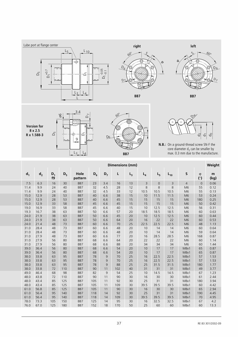
Adjustable-Preload Single Nut SEM-E-S
d0 = nominal diameter
P = lead
(R = right-hand, L = left-hand)
DW = ball diameter
i = number of ball track turns
Size Part number Load ratings Speed*
d0 x P x Dw - i C C0 vmax(N) (N) [m/min]
8 x 2.5R x 1.588 - 3 1532-2-3004 2200 2800 1512 x 5R x 2 - 3 1532-4-6024 3800 5800 3012 x 10R x 2 - 2 1532-4-9014 2500 3600 6016 x 5R x 3 - 4 1512-0-1024 12300 16100 3016 x 10R x 3 - 3 1512-0-4014 9600 12300 6016 x 16R x 3 - 2 1512-0-6014 6300 7600 9620 x 5R x 3 - 4 1512-1-1014 14300 21500 3020 x 20R x 3.5 - 2 1512-1-7014 9100 12100 12025 x 5R x 3 - 4 1512-2-1014 15900 27200 3025 x 10R x 3 - 4 1512-2-4014 15700 27000 6025 x 25R x 3.5 - 2 1512-2-8014 10100 15100 15032 x 5R x 3.5 - 4 1512-3-1014 21600 40000 2332 x 5L x 3.5 - 4 1552-3-1004 21600 40000 2332 x 10R x 3.969 - 5 1512-3-4014 31700 58300 4732 x 20R x 3.969 - 2 1512-3-7014 13500 21800 9432 x 32R x 3.969 - 2 1512-3-9014 13400 22000 15040 x 5R x 3.5 - 5 1512-4-1014 29100 64100 1940 x 5L x 3.5 - 5 1552-4-1004 29100 64100 1940 x 10R x 6 - 4 1512-4-4014 50000 86400 3840 x 10L x 6 - 4 1552-4-4004 50000 86400 3840 x 20R x 6 - 3 1512-4-7014 37900 62800 7540 x 40R x 6 - 2 1512-4-9014 25500 40300 15050 x 5R x 3.5 - 5 1512-5-1014 32000 81300 1550 x 10R x 6 - 6 1512-5-4014 79700 166500 3050 x 20R x 6.5 - 3 1512-5-7014 47900 87900 6050 x 40R x 6.5 - 2 1512-5-9014 32100 55800 12063 x 10R x 6 - 6 1512-6-4014 88800 214300 2463 x 20R x 6.5 - 3 1512-6-7014 53200 112100 4863 x 40R x 6.5 - 2 1512-6-9014 36900 74300 9580 x 10R x 6.5 - 6 1512-7-4014 108400 291700 1980 x 20R x 12.7 - 6 1512-7-7024 262700 534200 30
SEM-E-S 20 x 5R x 3-4 1 2 T7 R 82Z120 41Z120 1250 1 0Order code:
Standard series
* See P. 95 Characteristic speed d0 . n and P. 116 Critical speed nk
37 RE 83 301/2002-09
Version for8 x 2.5
R x 1.588-3
right leftLube port at flange center
BB7 BB7
BB7
Dimensions (mm) Weight
d1 d2 D1 D5 Hole D6 D7 L L3 L4 L5 L10 S ϕ mf9 pattern (°) (kg)
7.5 6.3 16 30 BB7 23 3.4 16 13 3 0 3 4 0 0.0611.4 9.9 24 40 BB7 32 4.5 28 12 8 8 8 M6 55 0.1211.4 9.9 24 40 BB7 32 4.5 33 12 10.5 10.5 10.5 M6 55 0.1315.0 12.9 28 53 BB7 40 6.6 38 15 10 11.5 11.5 M6 53 0.2415.0 12.9 28 53 BB7 40 6.6 45 15 15 15 15 M6 180 0.2515.0 12.9 33 58 BB7 45 6.6 45 15 15 15 15 M6 50 0.4219.0 16.9 33 58 BB7 45 6.6 40 15 10 12.5 12.5 M6 56 0.3119.3 16.7 38 63 BB7 50 6.6 57 20 18.5 18.5 18.5 M6 60 0.6324.0 21.9 38 63 BB7 50 6.6 45 20 10 12.5 12.5 M6 60 0.4424.0 21.9 38 63 BB7 50 6.6 64 20 16 22 22 M6 60 0.5324.0 21.4 48 73 BB7 60 6.6 70 25 22.5 22.5 22.5 M6 48 1.1331.0 28.4 48 73 BB7 60 6.6 48 20 10 14 14 M6 60 0.6431.0 28.4 48 73 BB7 60 6.6 48 20 10 14 14 M6 59 0.6431.0 27.9 48 73 BB7 60 6.6 77 20 16 28.5 28.5 M6 168 0.8731.0 27.9 56 80 BB7 68 6.6 64 20 22 22 22 M6 60 1.1431.0 27.9 56 80 BB7 68 6.6 88 20 34 34 34 M6 60 1.4439.0 36.4 56 80 BB7 68 6.6 54 20 10 17 17 M8x1 65 0.8739.0 36.4 56 80 BB7 68 6.6 54 20 10 17 17 M8x1 65 0.8738.0 33.8 63 95 BB7 78 9 70 25 16 22.5 22.5 M8x1 57 1.5338.0 33.8 63 95 BB7 78 9 70 25 16 22.5 22.5 M8x1 57 1.5338.0 33.8 63 95 BB7 78 9 88 25 25 31.5 31.5 M8x1 180 1.7738.0 33.8 72 110 BB7 90 11 102 40 31 31 31 M8x1 49 3.7749.0 46.4 68 98 BB7 82 9 54 25 10 14.5 14.5 M8x1 67 1.2348.0 43.8 72 110 BB7 90 11 90 30 16 30 30 M8x1 61 2.4448.0 43.4 85 125 BB7 105 11 92 30 25 31 31 M8x1 180 3.9448.0 43.4 85 125 BB7 105 11 109 30 39.5 39.5 39.5 M8x1 60 4.4261.0 56.8 85 125 BB7 105 11 90 30 16 30 30 M8x1 65 2.9461.0 56.4 95 140 BB7 118 14 92 30 25 31 31 M8x1 190 4.4561.0 56.4 95 140 BB7 118 14 109 30 39.5 39.5 39.5 M8x1 70 4.9578.0 73.3 105 150 BB7 125 14 95 30 16 32.5 32.5 M8x1 67 4.276.0 67.0 125 180 BB7 152 18 170 50 25 60 60 M8x1 60 13.3
L3
L
L 10
L 4
60°
D 7
S 60°
D7
S
D1
D1+
0.7
D5
D 1-0
.05
-0.1
L5
L3 L4
D5
D1
ø6 D7
3.460°
D6
S
9
Dw
d 0d 1d 2
D6 D6
ϕ ϕ
N.B.: On a ground-thread screw SN-F thecore diameter d2 can be smaller bymax. 0.3 mm due to the manufacture.
RE 83 301/2002-09 38
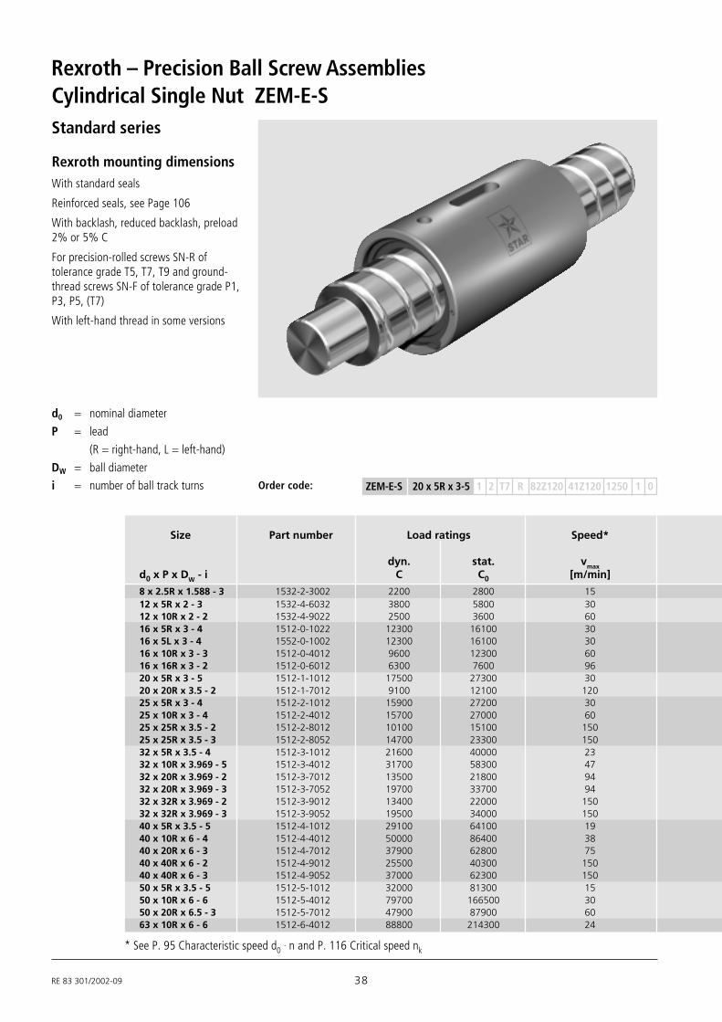
Rexroth – Precision Ball Screw AssembliesCylindrical Single Nut ZEM-E-S
d0 = nominal diameter
P = lead
(R = right-hand, L = left-hand)
DW = ball diameter
i = number of ball track turns
Rexroth mounting dimensionsWith standard seals
Reinforced seals, see Page 106
With backlash, reduced backlash, preload2% or 5% C
For precision-rolled screws SN-R oftolerance grade T5, T7, T9 and ground-thread screws SN-F of tolerance grade P1,P3, P5, (T7)
With left-hand thread in some versions
Size Part number Load ratings Speed*
dyn. stat. vmax
d0 x P x DW - i C C0 [m/min]
8 x 2.5R x 1.588 - 3 1532-2-3002 2200 2800 1512 x 5R x 2 - 3 1532-4-6032 3800 5800 3012 x 10R x 2 - 2 1532-4-9022 2500 3600 6016 x 5R x 3 - 4 1512-0-1022 12300 16100 3016 x 5L x 3 - 4 1552-0-1002 12300 16100 3016 x 10R x 3 - 3 1512-0-4012 9600 12300 6016 x 16R x 3 - 2 1512-0-6012 6300 7600 9620 x 5R x 3 - 5 1512-1-1012 17500 27300 3020 x 20R x 3.5 - 2 1512-1-7012 9100 12100 12025 x 5R x 3 - 4 1512-2-1012 15900 27200 3025 x 10R x 3 - 4 1512-2-4012 15700 27000 6025 x 25R x 3.5 - 2 1512-2-8012 10100 15100 15025 x 25R x 3.5 - 3 1512-2-8052 14700 23300 15032 x 5R x 3.5 - 4 1512-3-1012 21600 40000 2332 x 10R x 3.969 - 5 1512-3-4012 31700 58300 4732 x 20R x 3.969 - 2 1512-3-7012 13500 21800 9432 x 20R x 3.969 - 3 1512-3-7052 19700 33700 9432 x 32R x 3.969 - 2 1512-3-9012 13400 22000 15032 x 32R x 3.969 - 3 1512-3-9052 19500 34000 15040 x 5R x 3.5 - 5 1512-4-1012 29100 64100 1940 x 10R x 6 - 4 1512-4-4012 50000 86400 3840 x 20R x 6 - 3 1512-4-7012 37900 62800 7540 x 40R x 6 - 2 1512-4-9012 25500 40300 15040 x 40R x 6 - 3 1512-4-9052 37000 62300 15050 x 5R x 3.5 - 5 1512-5-1012 32000 81300 1550 x 10R x 6 - 6 1512-5-4012 79700 166500 3050 x 20R x 6.5 - 3 1512-5-7012 47900 87900 6063 x 10R x 6 - 6 1512-6-4012 88800 214300 24
ZEM-E-S 20 x 5R x 3-5 1 2 T7 R 82Z120 41Z120 1250 1 0Order code:
Standard series
* See P. 95 Characteristic speed d0 . n and P. 116 Critical speed nk

39 RE 83 301/2002-09
T1
L 7
L 6L 11
L
D1
A0.
2B
Dw
d 0d 1d 2
A
D4
Dimensions (mm) Weight
d1 d2 D1 D4 L L6 L7 L11 B T1 mg6 ±0.1 +0.2 P9 +0.1 (kg)
7.5 6.3 16 2 16 5 3.5 6 3 1.8 0.0211.4 9.9 24 2 28 8 3.5 12 5 3 0.0611.4 9.9 24 2 33 10.5 3.5 12 5 3 0.0715.0 12.9 28 4 35 14.5 9.5 12 5 3 0.0915.0 12.9 28 4 35 14.5 9.5 12 5 3 0.0915.0 12.9 28 4 45 14.5 9.5 16 5 3 0.1215.0 12.9 33 4 45 14.5 9.5 16 5 3 0.2019.0 16.9 33 4 45 14.5 9.5 16 5 3 0.1619.3 16.7 38 4 64 22 9.5 20 5 3 0.3424.0 21.9 38 4 45 14.5 9.5 16 5 3 0.1924.0 21.9 38 4 64 22 9.5 20 5 3 0.2824.0 21.4 48 4 80 30 10.5 20 5 3 0.7324.0 21.4 40 4 95 37.5 10.5 20 5 3 0.5031.0 28.4 48 4 48 14 9.5 20 5 3 0.3231.0 27.9 48 4 77 28.5 9.5 20 5 3 0.5031.0 27.9 56 4 64 22 9.5 20 5 3 0.7431.0 27.9 50 4 84 32 9.5 20 5 3 0.6631.0 27.9 56 4 88 34 9.5 20 5 3 1.0331.0 27.9 50 4 120 50 9.5 20 5 3 0.9739.0 36.4 56 4 54 17 9.5 20 5 3 0.4438.0 33.8 63 4 70 25 14 20 5 3 0.8838.0 33.8 63 4 88 34 14 20 5 3 1.1338.0 33.8 72 4 113 46.5 14 20 5 3 2.2338.0 33.8 63 4 142 61 14 20 5 3 1.8549.0 46.4 68 4 54 17 9.5 20 5 3 0.6248.0 43.8 72 5 90 35 14 20 5 3 1.3448.0 43.4 85 5 92 30 14 32 6 3.5 2.3961.0 56.8 85 5 90 29 14 32 6 3.5 1.59
Lube port
N.B.: On a ground-thread screw SN-F the core diameter d2 canbe smaller by max. 0.3 mm due to the manufacture.
RE 83 301/2002-09 40
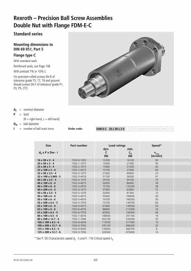
Rexroth – Precision Ball Screw AssembliesDouble Nut with Flange FDM-E-C
d0 = nominal diameter
P = lead
(R = right-hand, L = left-hand)
DW = ball diameter
i = number of ball track turns
Mounting dimensions toDIN 69 051, Part 5
Flange type CWith standard seals
Reinforced seals, see Page 106
With preload 7% or 10% C
For precision-rolled screws SN-R oftolerance grade T5, T7, T9 and ground-thread screws SN-F of tolerance grade P1,P3, P5, (T7)
Size Part number Load ratings Speed*dyn. stat.
d0 x P x Dw - i C C0 vmax
(N) (N) [m/min]16 x 5R x 3 - 4 1502-0-1055 12300 16100 3020 x 5R x 3 - 4 1502-1-1075 14300 21500 3025 x 5R x 3 - 4 1502-2-1075 15900 27200 3025 x 10R x 3 - 4 1502-2-4075 15700 27000 6032 x 5R x 3.5 - 4 1502-3-1075 21600 40000 2332 x 10R x 3.969 - 5 1502-3-4076 31700 58300 4740 x 5R x 3.5 - 5 1502-4-1076 29100 64100 1940 x 10R x 6 - 4 1502-4-4075 50000 86400 3840 x 10R x 6 - 6 1502-4-4076 72100 132200 3840 x 20R x 6 - 3 1502-4-7075 37900 62800 7550 x 5R x 3.5 - 5 1502-5-1076 32000 81300 1550 x 10R x 6 - 4 1502-5-4075 55400 109000 3050 x 10R x 6 - 6 1502-5-4076 79700 166500 3050 x 20R x 6.5 - 5 1502-5-7076 75700 149700 6063 x 10R x 6 - 4 1502-6-4075 61800 140500 2463 x 10R x 6 - 6 1502-6-4076 88800 214300 2463 x 20R x 6.5 - 5 1502-6-7076 83900 190300 4880 x 10R x 6.5 - 6 1502-7-4076 108400 291700 1980 x 20R x 12.7 - 6 1502-7-7046 262700 534200 30100 x 10R x 6.5 - 6 1502-8-4056 119500 371900 10100 x 20R x 12.7 - 6 1502-8-7056 295100 686400 20125 x 10R x 6.5 - 6 1502-9-4056 130600 468700 8125 x 20R x 12.7 - 6 1502-9-7056 326500 870400 16
FDM-E-C 20 x 5R x 3-4 1 2 T7 R 82Z120 41Z120 1250 1 0Order code:
Standard series
* See P. 95 Characteristic speed d0 . n and P. 116 Critical speed nk

41 RE 83 301/2002-09
LL 4L 3
90°
22.5°
90°
30°
30°
D7
D7
S
D6
S
D6
D5 D1
L 9L 9
L 10
D 1-0
.04
-0.2
Dw
d 0d 1d 2
d0 ≤ 32
d0 ≥ 40
Lube port at flange center
BB2
BB1
15.0 12.9 28 48 BB2 38 5.5 72 12 10 44 60 M6 0.2919.0 16.9 36 58 BB2 47 6.6 82 12 10 51 70 M6 0.5324.0 21.9 40 62 BB2 51 6.6 82 12 10 55 70 M6 0.5724.0 21.9 40 62 BB2 51 6.6 120 12 16 55 108 M6 0.7731.0 28.4 50 80 BB2 65 9 88 13 10 71 75 M6 0.9631.0 27.9 50 80 BB2 65 9 146 13 16 71 133 M6 1.3439.0 36.4 63 93 BB1 78 9 100 15 10 81.5 85 M8x1 1.6838.0 33.8 63 93 BB1 78 9 140 15 16 81.5 125 M8x1 2.1538.0 33.8 63 93 BB1 78 9 180 15 16 81.5 165 M8x1 2.7338.0 33.8 63 93 BB1 78 9 175 15 25 81.5 160 M8x1 2.5649.0 46.4 75 110 BB1 93 11 100 15 10 97.5 85 M8x1 2.2548.0 43.8 75 110 BB1 93 11 140 18 16 97.5 122 M8x1 2.9748.0 43.8 75 110 BB1 93 11 180 18 16 97.5 162 M8x1 3.7348.0 43.4 75 110 BB1 93 11 255 18 25 97.5 237 M8x1 4.9361.0 56.8 90 125 BB1 108 11 140 22 16 110 118 M8x1 461.0 56.8 90 125 BB1 108 11 180 22 16 110 158 M8x1 4.4561.0 56.4 95 135 BB1 115 13.5 255 22 25 117.5 233 M8x1 8.2178.0 73.3 105 145 BB1 125 13.5 190 22 16 127.5 168 M8x1 5.9376.0 67.0 125 165 BB1 145 13.5 340 25 25 147.5 315 M8x1 19.498.0 93.4 125 165 BB1 145 13.5 190 25 16 147.5 165 M8x1 7.3596.0 87.1 150 202 BB1 176 17.5 340 30 25 178.5 310 M8x1 24.6123.0 118.0 150 202 BB1 176 17.5 190 25 16 178.5 165 M8x1 9.38121.0 112.0 170 222 BB1 196 17.5 340 40 25 198.5 300 M8x1 29.7
Dimensions (mm) Weight
d1 d2 D1 D5 Hole D6 D7 L L3 L4 L9 L10 S mg6 pattern (kg)
N.B.: On a ground-thread screw SN-F the core diameter d2 canbe smaller by max. 0.3 mm due to the manufacture.
RE 83 301/2002-09 42
Rexroth – Precision Ball Screw AssembliesDouble Nut with Flange FDM-E-S
d0 = nominal diameter
P = lead
(R = right-hand, L = left-hand)
DW = ball diameter
i = number of ball track turns
Rexroth mounting dimensionsWith standard seals
Reinforced seals, see Page 106
With preload 7% or 10% C
For precision-rolled screws SN-R oftolerance grade T5, T7, T9 and ground-thread screws SN-F of tolerance grade P1,P3, P5, (T7)
Size Part number Load ratings Speed*dyn. stat.
d0 x P x Dw - i C C0 vmax
(N) (N) [m/min]16 x 5R x 3 - 4 1502-0-1023 12300 16100 3020 x 5R x 3 - 4 1502-1-1033 14300 21500 3025 x 5R x 3 - 4 1502-2-1033 15900 27200 3025 x 10R x 3 - 4 1502-2-4033 15700 27000 6032 x 5R x 3.5 - 4 1502-3-1033 21600 40000 2332 x 10R x 3.969 - 5 1502-3-4033 31700 58300 4740 x 5R x 3.5 - 5 1502-4-1033 29100 64100 1940 x 10R x 6 - 4 1502-4-4033 50000 86400 3840 x 10R x 6 - 6 1502-4-4034 72100 132200 3840 x 20R x 6 - 3 1502-4-7033 37900 62800 7550 x 5R x 3.5 - 5 1502-5-1033 32000 81300 1550 x 10R x 6 - 4 1502-5-4033 55400 109000 3050 x 10R x 6 - 6 1502-5-4034 79700 166500 3050 x 20R x 6.5 - 5 1502-5-7034 75700 149700 6063 x 10R x 6 - 4 1502-6-4033 61800 140500 2463 x 10R x 6 - 6 1502-6-4034 88800 214300 2463 x 20R x 6.5 - 5 1502-6-7034 83900 190300 4880 x 10R x 6.5 - 6 1502-7-4034 108400 291700 1980 x 20R x 12.7 - 6 1502-7-7004 262700 534200 30100 x 10R x 6.5 - 6 1502-8-4024 119500 371900 10100 x 20R x 12.7 - 6 1502-8-7024 295100 686400 20125 x 10R x 6.5 - 6 1502-9-4024 130600 468700 8125 x 20R x 12.7 - 6 1502-9-7024 326500 870400 16
FDM-E-S 20 x 5R x 3-4 1 2 T7 R 82Z120 41Z120 1250 1 0Order code:
Standard series
* See P. 95 Characteristic speed d0 . n and P. 116 Critical speed nk

43 RE 83 301/2002-09
L
L 4L 3
6x6
0°
30°
D7
S
4x90°
45°
S
10x3
6°
S
18°
D7
8x4
5°
22
.5°
S
D7
D5 D1
D 1-0
.04
-0.2
L 10
Dw
d 0d 1d 2
D6
D7
D6
D6
D6
Lube port at flange centerBB4BB3
BB6BB5
15.0 12.9 28 53 BB3 40 6.6 72 12 10 60 M6 0.3319.0 16.9 33 58 BB4 45 6.6 82 12 10 70 M6 0.4524.0 21.9 38 63 BB4 50 6.6 82 12 10 70 M6 0.5324.0 21.9 38 63 BB4 50 6.6 120 12 16 108 M6 0.7031.0 28.4 48 73 BB4 60 6.6 88 13 10 75 M6 0.8431.0 27.9 48 73 BB4 60 6.6 146 13 16 133 M6 1.2239.0 36.4 56 80 BB4 68 6.6 100 15 10 85 M8x1 1.1338.0 33.8 63 95 BB4 78 9 140 15 16 125 M8x1 2.2538.0 33.8 63 95 BB4 78 9 180 15 16 165 M8x1 2.8338.0 33.8 63 95 BB4 78 9 175 15 25 160 M8x1 2.6649.0 46.4 68 98 BB4 82 9 100 15 10 85 M8x1 1.6048.0 43.8 72 110 BB4 90 11 140 18 16 122 M8x1 2.7448.0 43.8 72 110 BB4 90 11 180 18 16 162 M8x1 3.3948.0 43.4 85 125 BB4 105 11 255 22 25 233 M8x1 6.7161.0 56.8 85 125 BB4 105 11 140 22 16 118 M8x1 3.5361.0 56.8 85 125 BB4 105 11 180 22 16 158 M8x1 4.3261.0 56.4 95 140 BB4 118 14 255 22 25 233 M8x1 8.6578.0 73.3 105 150 BB4 125 14 190 22 16 168 M8x1 6.3576.0 67.0 125 180 BB5 152 18 340 25 25 315 M8x1 20.2098.0 93.4 125 180 BB5 152 18 190 25 16 165 M8x1 8.1996.0 87.1 145 200 BB5 172 18 340 30 25 310 M8x1 24.50123.0 118.0 150 210 BB5 180 18 190 30 16 160 M8x1 10.80121.0 112.0 170 230 BB6 200 18 340 40 25 300 M8x1 31.00
Dimensions (mm) Weight
d1 d2 D1 D5 Hole D6 D7 L L3 L4 L10 S mg6 pattern (kg)
N.B.: On a ground-thread screw SN-F the core diameter d2 canbe smaller by max. 0.3 mm due to the manufacture.
RE 83 301/2002-09 44
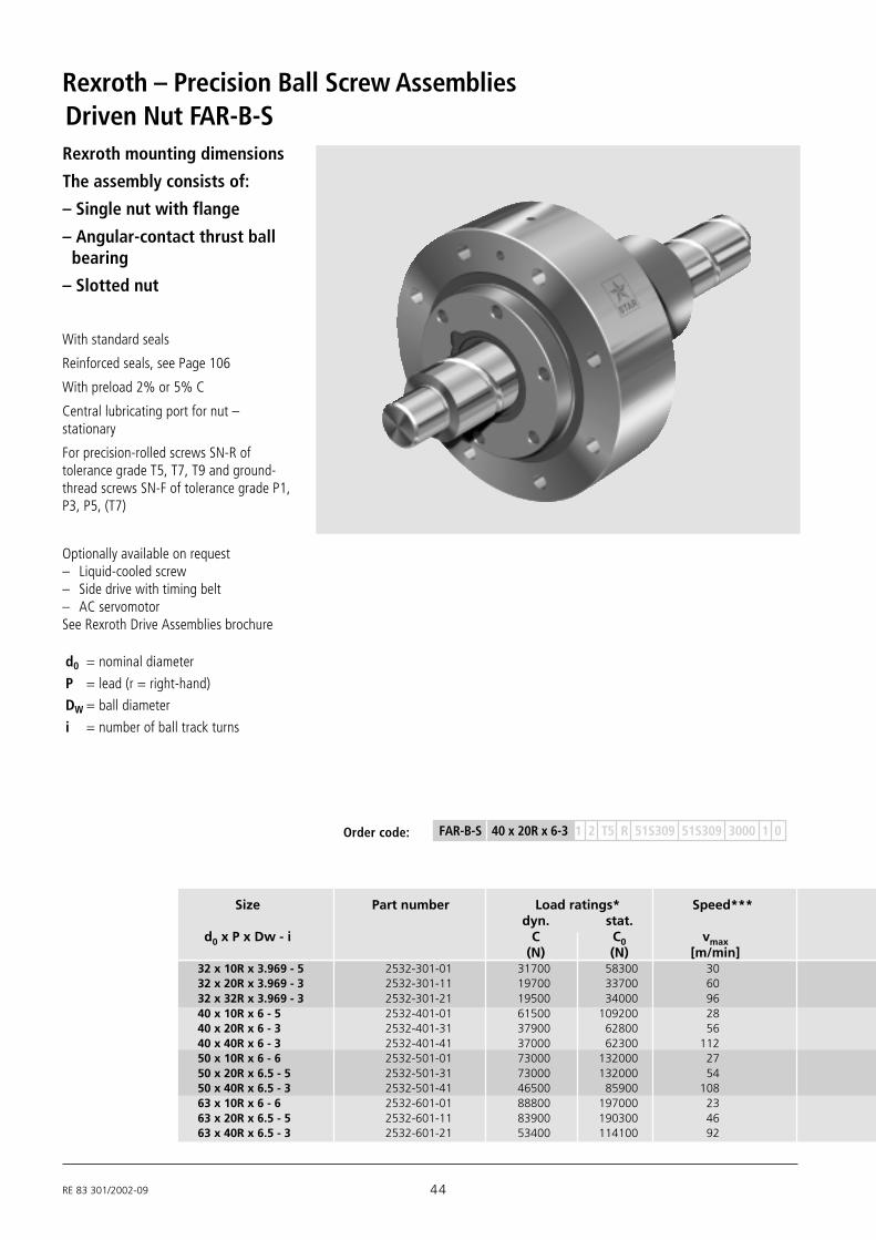
Rexroth – Precision Ball Screw Assemblies
Rexroth mounting dimensions
The assembly consists of:
– Single nut with flange
– Angular-contact thrust ball bearing
– Slotted nut
With standard seals
Reinforced seals, see Page 106
With preload 2% or 5% C
Central lubricating port for nut –stationary
For precision-rolled screws SN-R oftolerance grade T5, T7, T9 and ground-thread screws SN-F of tolerance grade P1,P3, P5, (T7)
Optionally available on request– Liquid-cooled screw– Side drive with timing belt– AC servomotorSee Rexroth Drive Assemblies brochure
Driven Nut FAR-B-S
Size Part number Load ratings* Speed***dyn. stat.
d0 x P x Dw - i C C0 vmax(N) (N) [m/min]
32 x 10R x 3.969 - 5 2532-301-01 31700 58300 3032 x 20R x 3.969 - 3 2532-301-11 19700 33700 6032 x 32R x 3.969 - 3 2532-301-21 19500 34000 9640 x 10R x 6 - 5 2532-401-01 61500 109200 2840 x 20R x 6 - 3 2532-401-31 37900 62800 5640 x 40R x 6 - 3 2532-401-41 37000 62300 11250 x 10R x 6 - 6 2532-501-01 73000 132000 2750 x 20R x 6.5 - 5 2532-501-31 73000 132000 5450 x 40R x 6.5 - 3 2532-501-41 46500 85900 10863 x 10R x 6 - 6 2532-601-01 88800 197000 2363 x 20R x 6.5 - 5 2532-601-11 83900 190300 4663 x 40R x 6.5 - 3 2532-601-21 53400 114100 92
Order code:
d0 = nominal diameter
P = lead (r = right-hand)
DW = ball diameter
i = number of ball track turns
FAR-B-S 40 x 20R x 6-3 1 2 T5 R 51S309 51S309 3000 1 0
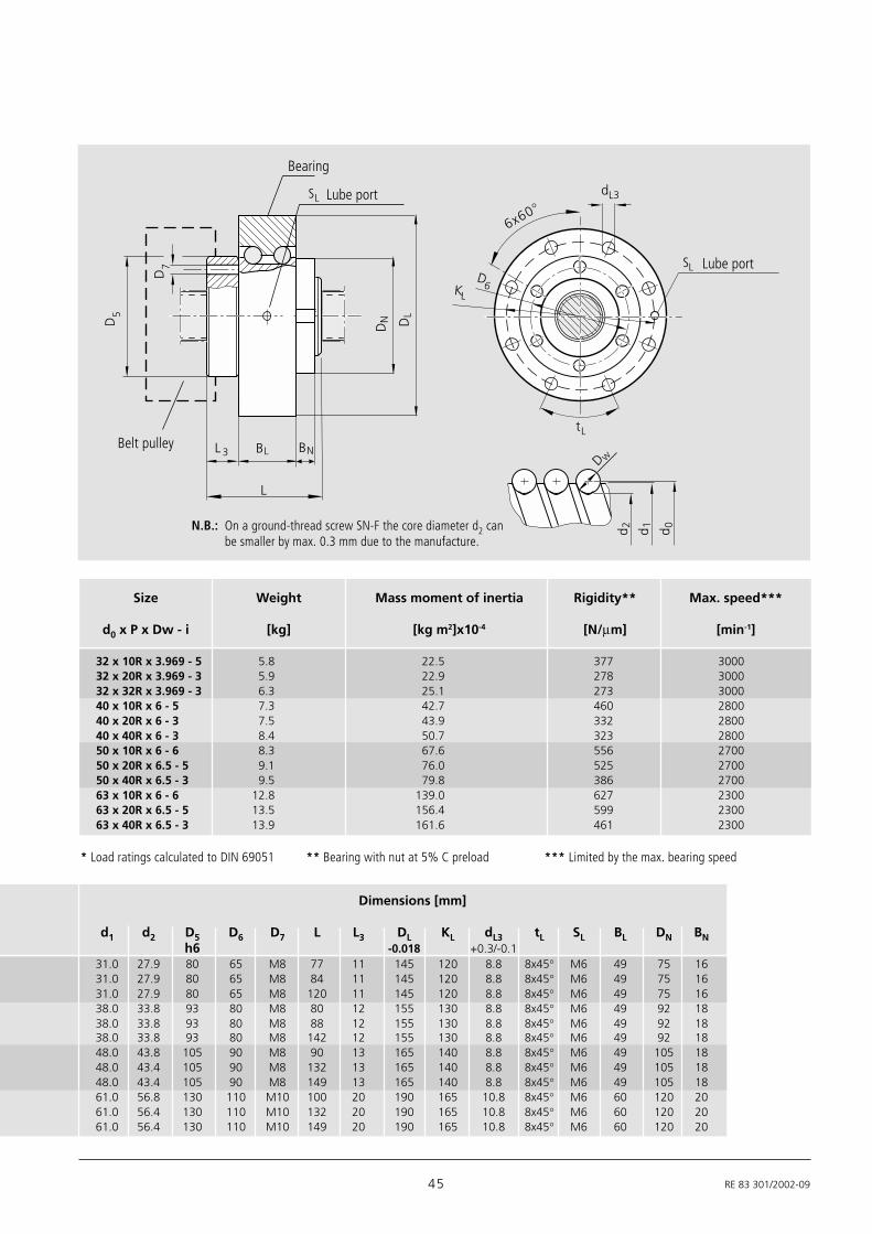
45 RE 83 301/2002-09
Size Weight Mass moment of inertia Rigidity** Max. speed***
d0 x P x Dw - i [kg] [kg m2]x10-4 [N/µm] [min-1]
32 x 10R x 3.969 - 5 5.8 22.5 377 300032 x 20R x 3.969 - 3 5.9 22.9 278 300032 x 32R x 3.969 - 3 6.3 25.1 273 300040 x 10R x 6 - 5 7.3 42.7 460 280040 x 20R x 6 - 3 7.5 43.9 332 280040 x 40R x 6 - 3 8.4 50.7 323 280050 x 10R x 6 - 6 8.3 67.6 556 270050 x 20R x 6.5 - 5 9.1 76.0 525 270050 x 40R x 6.5 - 3 9.5 79.8 386 270063 x 10R x 6 - 6 12.8 139.0 627 230063 x 20R x 6.5 - 5 13.5 156.4 599 230063 x 40R x 6.5 - 3 13.9 161.6 461 2300
* Load ratings calculated to DIN 69051
Lube port
Bearing
Belt pulley
Lube port
6x60°
D6
BLL 3
L
Dw
d 0d 1d 2
D5
BN
DN DL
dL3SL
KL
tL
D7 SL
Dimensions [mm]
d1 d2 D5 D6 D7 L L3 DL KL dL3 tL SL BL DN BNh6 -0.018 +0.3/-0.1
31.0 27.9 80 65 M8 77 11 145 120 8.8 8x45° M6 49 75 1631.0 27.9 80 65 M8 84 11 145 120 8.8 8x45° M6 49 75 1631.0 27.9 80 65 M8 120 11 145 120 8.8 8x45° M6 49 75 1638.0 33.8 93 80 M8 80 12 155 130 8.8 8x45° M6 49 92 1838.0 33.8 93 80 M8 88 12 155 130 8.8 8x45° M6 49 92 1838.0 33.8 93 80 M8 142 12 155 130 8.8 8x45° M6 49 92 1848.0 43.8 105 90 M8 90 13 165 140 8.8 8x45° M6 49 105 1848.0 43.4 105 90 M8 132 13 165 140 8.8 8x45° M6 49 105 1848.0 43.4 105 90 M8 149 13 165 140 8.8 8x45° M6 49 105 1861.0 56.8 130 110 M10 100 20 190 165 10.8 8x45° M6 60 120 2061.0 56.4 130 110 M10 132 20 190 165 10.8 8x45° M6 60 120 2061.0 56.4 130 110 M10 149 20 190 165 10.8 8x45° M6 60 120 20
N.B.: On a ground-thread screw SN-F the core diameter d2 canbe smaller by max. 0.3 mm due to the manufacture.
*** Limited by the max. bearing speed** Bearing with nut at 5% C preload
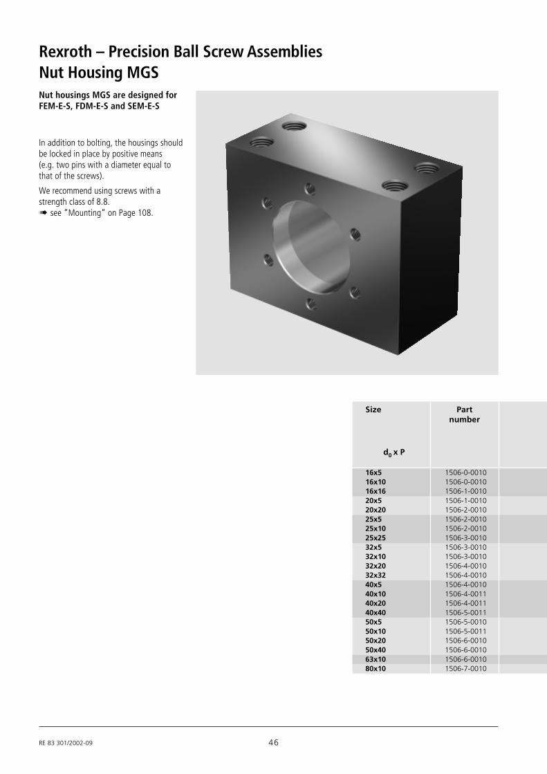
RE 83 301/2002-09 46
Rexroth – Precision Ball Screw Assemblies
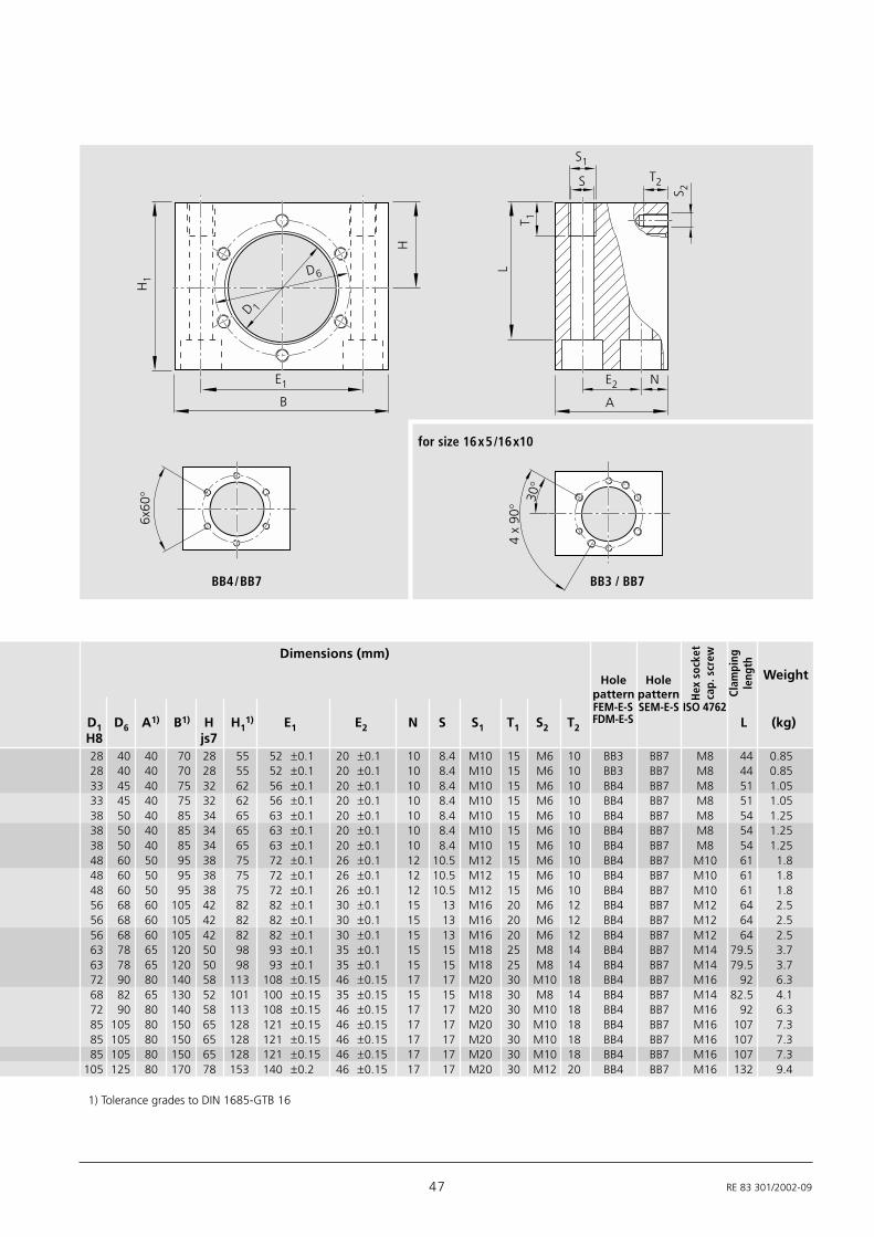
In addition to bolting, the housings shouldbe locked in place by positive means(e.g. two pins with a diameter equal tothat of the screws).
We recommend using screws with astrength class of 8.8.! see “Mounting“ on Page 108.
Nut Housing MGS
d0 x P
16x5 1506-0-001016x10 1506-0-001016x16 1506-1-001020x5 1506-1-001020x20 1506-2-001025x5 1506-2-001025x10 1506-2-001025x25 1506-3-001032x5 1506-3-001032x10 1506-3-001032x20 1506-4-001032x32 1506-4-001040x5 1506-4-001040x10 1506-4-001140x20 1506-4-001140x40 1506-5-001150x5 1506-5-001050x10 1506-5-001150x20 1506-6-001050x40 1506-6-001063x10 1506-6-001080x10 1506-7-0010
Size Partnumber
Nut housings MGS are designed forFEM-E-S, FDM-E-S and SEM-E-S
47 RE 83 301/2002-09
L
T 1
S1
S T2
S 2
E2 N
A
4 x
90°
6x60
°H
1
E1
BH
D6
D 1
30°
BB4/BB7 BB3 / BB7
for size 16x5/16x10
Weight
FEM-E-S SEM-E-S ISO 4762D1 D6 A1) B1) H H1
1) E1 E2 N S S1 T1 S2 T2 L (kg)H8 js728 40 40 70 28 55 52 ±0.1 20 ±0.1 10 8.4 M10 15 M6 10 BB3 BB7 M8 44 0.8528 40 40 70 28 55 52 ±0.1 20 ±0.1 10 8.4 M10 15 M6 10 BB3 BB7 M8 44 0.8533 45 40 75 32 62 56 ±0.1 20 ±0.1 10 8.4 M10 15 M6 10 BB4 BB7 M8 51 1.0533 45 40 75 32 62 56 ±0.1 20 ±0.1 10 8.4 M10 15 M6 10 BB4 BB7 M8 51 1.0538 50 40 85 34 65 63 ±0.1 20 ±0.1 10 8.4 M10 15 M6 10 BB4 BB7 M8 54 1.2538 50 40 85 34 65 63 ±0.1 20 ±0.1 10 8.4 M10 15 M6 10 BB4 BB7 M8 54 1.2538 50 40 85 34 65 63 ±0.1 20 ±0.1 10 8.4 M10 15 M6 10 BB4 BB7 M8 54 1.2548 60 50 95 38 75 72 ±0.1 26 ±0.1 12 10.5 M12 15 M6 10 BB4 BB7 M10 61 1.848 60 50 95 38 75 72 ±0.1 26 ±0.1 12 10.5 M12 15 M6 10 BB4 BB7 M10 61 1.848 60 50 95 38 75 72 ±0.1 26 ±0.1 12 10.5 M12 15 M6 10 BB4 BB7 M10 61 1.856 68 60 105 42 82 82 ±0.1 30 ±0.1 15 13 M16 20 M6 12 BB4 BB7 M12 64 2.556 68 60 105 42 82 82 ±0.1 30 ±0.1 15 13 M16 20 M6 12 BB4 BB7 M12 64 2.556 68 60 105 42 82 82 ±0.1 30 ±0.1 15 13 M16 20 M6 12 BB4 BB7 M12 64 2.563 78 65 120 50 98 93 ±0.1 35 ±0.1 15 15 M18 25 M8 14 BB4 BB7 M14 79.5 3.763 78 65 120 50 98 93 ±0.1 35 ±0.1 15 15 M18 25 M8 14 BB4 BB7 M14 79.5 3.772 90 80 140 58 113 108 ±0.15 46 ±0.15 17 17 M20 30 M10 18 BB4 BB7 M16 92 6.368 82 65 130 52 101 100 ±0.15 35 ±0.15 15 15 M18 30 M8 14 BB4 BB7 M14 82.5 4.172 90 80 140 58 113 108 ±0.15 46 ±0.15 17 17 M20 30 M10 18 BB4 BB7 M16 92 6.385 105 80 150 65 128 121 ±0.15 46 ±0.15 17 17 M20 30 M10 18 BB4 BB7 M16 107 7.385 105 80 150 65 128 121 ±0.15 46 ±0.15 17 17 M20 30 M10 18 BB4 BB7 M16 107 7.385 105 80 150 65 128 121 ±0.15 46 ±0.15 17 17 M20 30 M10 18 BB4 BB7 M16 107 7.3
105 125 80 170 78 153 140 ±0.2 46 ±0.15 17 17 M20 30 M12 20 BB4 BB7 M16 132 9.4
Holepattern
Holepattern H
ex s
ocke
tca
p. s
crew
Clam
ping
leng
th
Dimensions (mm)
1) Tolerance grades to DIN 1685-GTB 16
FDM-E-S

RE 83 301/2002-09 48
Rexroth – Precision Ball Screw Assemblies
In addition to bolting, the housings shouldbe locked in place by positive means(e.g. two pins with a diameter equal tothat of the screws).
We recommend using screws with astrength class of 8.8.! see “Mounting“ on Page 108.
Reference edges are formed on both sides.
Nut housings MGD are designed forFEM-E-C, FDM-E-C and SEM-E-C
Nut Housing MGD
Size Partnumber
16x516x10 1506-0-005016x1620x5
1506-1-005020x2025x525x10 1506-2-005025x2532x532x10
1506-3-005032x2032x3240x540x1040x12
1506-4-005040x1640x2040x4050x550x1050x12
1506-5-005050x1650x2050x4063x10 1506-6-005063x20
1506-6-005163x4080x10 1506-7-005080x20 1506-7-0051
d0 x P

49 RE 83 301/2002-09
90°
90°
30°
2 x B
H1
H2
H
B
E1N
T 1
S1
S T2
S 2
E2
A
D 6
D 1
L
BB2 BB1
Weight
D1 D6 A B H H1 H2 E1 E2 N S S1 T1 S2 T2 ISO 4762 L (kg)H7 ±0.01 ±0.01
Holepattern
Hex socketcap. screw
Clampinglength
Dimensions (mm)
28 38 50 35 24 48 10 50 ±0.1 20 ±0.1 20 8.4 M10 15 M5 10 BB2 M8 37 0.91
36 47 55 37.5 28 56 10 55 ±0.1 23 ±0.1 22 8.4 M10 15 M6 11 BB2 M8 45 1.18
40 51 55 40 30 60 10 60 ±0.1 23 ±0.1 22 8.4 M10 15 M6 11 BB2 M8 49 1.33
50 65 70 50 35 70 10 75 ±0.1 30 ±0.1 27 13 M16 20 M8 14 BB2 M12 52 2.27
63 78 80 60 42 84 12 90 ±0.1 35 ±0.1 31 15 M18 25 M8 17 BB1 M14 65.5 3.61
75 93 95 70 48 96 12 110 ±0.15 45 ±0.15 34 17 M20 30 M10 17 BB1 M16 75 5.63
90 108 100 75 55 110 15 120 ±0.2 46 ±0.15 37 17 M20 30 M10 20 BB1 M16 89 6.72
95 115 100 80 58 116 15 130 ±0.2 46 ±0.15 37 17 M20 30 M12 20 BB1 M16 95 7.67
105 125 100 85 63 126 15 140 ±0.2 46 ±0.15 37 17 M20 30 M12 20 BB1 M16 105 8.60125 145 100 95 73 146 15 160 ±0.2 46 ±0.15 37 17 M20 30 M12 22 BB1 M16 125 10.53

RE 83 301/2002-09 50
Rexroth – Precision Ball Screw Assemblies
L
d 0d 1d 2
D w
Please state lengths in the “Inquiry/Order Form“
Lov = overall length
Precision-Rolled Screw SN-R
Size Part number Maximum lengthTolerance Tolerance Tolerance Moment of Stan- on Weight
grade grade grade inertia dard Requestd0 x P x Dw T5 T7 T9 d1 d2 Js
(mm) (mm) (kgcm2/m) (kg/m)
SN 20 x 5R x 3 X X T7 R 82K120 41Z120 1250 1 0Order code:
available upon request
6x1Rx0.8 1531-1-0500 1531-1-0700 1531-1-0900 6.0 5.3 0.02 0.196x2Rx0.8 1531-1-2500 1531-1-2700 1531-1-2900 6.0 5.3 0.02 0.198x1Rx0.8 1531-2-0500 1531-2-0700 1531-2-0900 8.0 7.3 0.04 0.368x2Rx1.2 1531-2-2500 1531-2-2700 1531-2-2900 8.0 7.1 0.04 0.368 x2.5Rx1.588 1531-2-3500 1531-2-3700 1531-2-3900 7.5 6.3 0.04 0.3012x2Rx1.2 1531-4-2500 1531-4-2700 1531-4-2900 11.7 10.8 0.13 0.7912x5Rx2 1531-4-6510 1531-4-6710 1531-4-6910 11.4 9.9 0.11 0.7512x10Rx2 1531-4-9500 1531-4-9700 1531-4-9900 11.4 9.9 0.11 0.7416x5Lx3 1551-0-1500 1551-0-1700 1551-0-1900 15 12.9 0.31 1.2416x5Rx3 1511-0-1500 1511-0-1700 1511-0-1900 15 12.9 0.31
1500 25001.24
16x10Rx3 1511-0-4500 1511-0-4700 1511-0-4900 15 12.9 0.31 1.2316x16Rx3 1511-0-6510 1511-0-6710 1511-0-6910 15 12.9 0.34 1.2920x5Rx3 1511-1-1500 1511-1-1700 1511-1-1900 19 16.9 0.84 2.0320x40Rx3.5-4 2521-150-00 2521-170-00 2521-190-00 19 16.4 0.86 2.0620x20Rx3.5 1511-1-7510 1511-1-7710 1511-1-7910 19.3 16.7 0.81 1.9925x5Rx3 1511-2-1500 1511-2-1700 1511-2-1900 24 21.9 2.22 3.3125x10Rx3 1511-2-4500 1511-2-4700 1511-2-4900 24 21.9 2.39 3.4325x25Rx3.5 1511-2-8510 1511-2-8710 1511-2-8910 24 21.4 2.15 3.2532x5Rx3.5 1511-3-1500 1511-3-1700 1511-3-1900 31 28.4 6.05
2500 50005.45
32x5Lx3.5 1551-3-1500 1551-3-1700 1551-3-1900 31 28.4 6.05 5.4532x10Rx3.969 1511-3-4510 1511-3-4710 1511-3-4910 31 27.9 6.40 5.6032x20Rx3.969 1511-3-7510 1511-3-7710 1511-3-7910 31 27.9 6.39 5.6032x32Rx3.969 1511-3-9510 1511-3-9710 1511-3-9910 31 27.9 6.17 5.5040x5Rx3.5 1511-4-1500 1511-4-1700 1511-4-1900 39 36.4 15.64
4500 50008.78
40x5Lx3.5 1551-4-1500 1551-4-1700 1551-4-1900 39 36.4 15.64 8.7840x10Rx6 1511-4-4500 1511-4-4700 1511-4-4900 38 33.8 13.55 8.1540x10Lx6 1551-4-4500 1551-4-4700 1551-4-4900 38 33.8 13.55 8.1540x12Rx6 1511-4-5500 1511-4-5700 1511-4-5900 38 33.8 13.97 8.2740x16Rx6 1511-4-6500 1511-4-6700 1511-4-6900 38 33.8 12.90
4500 75007.95
40x20Rx6 1511-4-7500 1511-4-7700 1511-4-7900 38 33.8 13.52 8.1440x40Rx6 1511-4-9510 1511-4-9710 1511-4-9910 38 33.8 13.42 8.1150x5Rx3.5 1511-5-1500 1511-5-1700 1511-5-1900 49 46.4 40.03 4500 5000 14.0550x10Rx6 1511-5-4500 1511-5-4700 1511-5-4900 48 43.8 35.71 13.2550x12Rx6 1511-5-5500 1511-5-5700 1511-5-5900 48 43.8 36.58 13.4150x16Rx6 1511-5-6500 1511-5-6700 1511-5-6900 48 43.8 34.37 13.0050x20Rx6.5 1511-5-7510 1511-5-7710 1511-5-7910 48 43.3 34.50 13.0150x40Rx6.5 1511-5-9510 1511-5-9710 1511-5-9910 48 43.3 34.34
4500 750012.98
63x10Rx6 1511-6-4500 1511-6-4700 1511-6-4900 61 56.8 95.82 21.7263x20Rx6.5 1511-6-7510 1511-6-7710 1511-6-7910 61 56.3 93.29 21.4263x40Rx6.5 1511-6-9510 1511-6-9710 1511-6-9910 61 56.3 93.08 21.4080x10Rx6.5 1511-7-4500 1511-7-4700 1511-7-4900 78 73.3 256.86 35.58
51 RE 83 301/2002-09
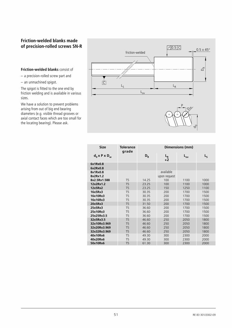
Friction-welded blanks consist of
– a precision-rolled screw part and
– an unmachined spigot.
The spigot is fitted to the one end byfriction welding and is available in varioussizes.
We have a solution to prevent problemsarising from out of big end bearingdiameters (e.g. visible thread grooves oraxial contact faces which are too small forthe locating bearing). Please ask.
Friction-welded blanks madeof precision-rolled screws SN-R
friction-welded
Size Tolerance Dimensions (mm)grade
d0 x P x Dw DR LR Lov LS+2
6x1Rx0.86x2Rx0.88x1Rx0.88x2Rx1.28x2.5Rx1.588 T5 14.25 100 1100 100012x2Rx1.2 T5 23.25 100 1100 100012x5Rx2 T5 23.25 150 1250 110016x5Rx3 T5 30.35 200 1700 150016x10Rx3 T5 30.35 200 1700 150016x16Rx3 T5 30.35 200 1700 150020x5Rx3 T5 31.50 200 1700 150025x5Rx3 T5 36.60 200 1700 150025x10Rx3 T5 36.60 200 1700 150025x25Rx3.5 T5 36.60 200 1700 150032x5Rx3.5 T5 46.60 250 2050 180032x10Rx3.969 T5 46.60 250 2050 180032x20Rx3.969 T5 46.60 250 2050 180032x32Rx3.969 T5 46.60 250 2050 180040x10Rx6 T5 49.30 300 2300 200040x20Rx6 T5 49.30 300 2300 200050x10Rx6 T5 61.30 300 2300 2000
availableupon request
C
d 0
P
DR
LR
Lov
LS
0.5 x 45° 0.5 C
Dw

RE 83 301/2002-09 52
Rexroth – Precision Ball Screw AssembliesGround-Thread Screw SN-F
Size Part number Maximum lengthTolerance Tolerance Tolerance Moment of available on Weight
grade grade grade inertia at short requestd0 x P x Dw P1 P3 P5 d1 d2 Js notice
(mm) (mm) (kgcm2/m) (kg/m)8 x 2.5R x 1.588 – 1521- 2 -3300 1521- 2 -3500 7.5 6.2 0.02 800 1500 0.3012 x 5R x 2 – 1521- 4 -6310 1521- 4 -6510 11.4 9.8 0.11 800 1500 0.7512 x 10R x 2 – 1521- 4 -9300 1521- 4 -9500 11.4 9.8 0.12 800 1500 0.7316 x 5R x 3 1501- 0 -1100 1501- 0 -1300 1501- 0 -1500 15 12.8 0.31 1000 3000 1.2416 x 10R x 3 1501- 0 -4100 1501- 0 -4300 1501- 0 -4500 15 12.8 0.35 1000 3000 1.3116 x 16R x 3 1501- 0 -6110 1501- 0 -6310 1501- 0 -6510 15 12.8 0.37 1000 3000 1.3420 x 5R x 3 1501- 1 -1100 1501- 1 -1300 1501- 1 -1500 19 16.8 0.85 1200 3000 2.0320 x 20R x 3.5 1501- 1 -7110 1501- 1 -7310 1501- 1 -7510 19.3 16.6 1.01 1200 3000 2.2225 x 5R x 3 1501- 2 -1100 1501- 2 -1300 1501- 2 -1500 24 21.8 2.23 1500 5000 3.3125 x 10R x 3 1501- 2 -4100 1501- 2 -4300 1501- 2 -4500 24 21.8 2.39 1500 5000 3.4325 x 25R x 3.5 1501- 2 -8110 1501- 2 -8310 1501- 2 -8510 24 21.3 2.46 1500 5000 3.4832 x 5R x 3.5 1501- 3 -1100 1501- 3 -1300 1501- 3 -1500 31 28.3 6.05 3000 5000 5.4532 x 10R x 3.969 1501- 3 -4110 1501- 3 -4310 1501- 3 -4510 31 27.8 6.40 3000 5000 5.6032 x 20R x 3.969 1501- 3 -7110 1501- 3 -7310 1501- 3 -7510 31 27.8 6.76 3000 5000 5.7632 x 32R x 3.969 1501- 3 -9110 1501- 3 -9310 1501- 3 -9510 31 27.8 6.89 3000 5000 5.8340 x 5R x 3.5 1501- 4 -1100 1501- 4 -1300 1501- 4 -1500 39 36.3 15.66 4000 5000 8.7840 x 10R x 6 1501- 4 -4100 1501- 4 -4300 1501- 4 -4500 38 33.7 13.53 5000 8000 8.1440 x 12R x 6 1501- 4 -5100 1501- 4 -5300 1501- 4 -5500 38 33.7 13.40 5000 8000 8.2740 x 16R x 6 1501- 4 -6100 1501- 4 -6300 1501- 4 -6500 38 33.7 14.48 5000 8000 8.4340 x 20R x 6 1501- 4 -7100 1501- 4 -7300 1501- 4 -7500 38 33.7 14.80 5000 8000 8.5240 x 40R x 6 1501- 4 -9110 1501- 4 -9310 1501- 4 -9510 38 33.7 15.42 5000 8000 8.7150 x 5R x 3.5 1501- 5 -1100 1501- 5 -1300 1501- 5 -1500 49 46.3 40.06 4000 5000 14.0550 x 10R x 6 1501- 5 -4100 1501- 5 -4300 1501- 5 -4500 48 43.7 35.57 5000 8000 13.2450 x 12R x 6 1501- 5 -5100 1501- 5 -5300 1501- 5 -5500 48 43.7 36.55 5000 8000 13.4050 x 16R x 6 1501- 5 -6100 1501- 5 -6300 1501- 5 -6500 48 43.7 37.64 5000 8000 13.6050 x 20R x 6.5 1501- 5 -7110 1501- 5 -7310 1501- 5 -7510 48 43.2 37.70 5000 8000 13.6150 x 40R x 6.5 1501- 5 -9110 1501- 5 -9310 1501- 5 -9510 48 43.2 39.29 5000 8000 13.9163 x 10R x 6 1501- 6 -4100 1501- 6 -4300 1501- 6 -4500 61 56.7 95.71 5000 8000 21.7163 x 20R x 6.5 1501- 6 -7110 1501- 6 -7310 1501- 6 -7510 61 56.2 99.98 5000 8000 22.1863 x 40R x 6.5 1501- 6 -9110 1501- 6 -9310 1501- 6 -9510 61 56.2 103.36 5000 8000 22.5780 x 10R x 6.5 1501- 7 -4100 1501- 7 -4300 1501- 7 -4500 78 73.2 256.36 5000 8000 35.5480 x 20R x 9 1501- 7 -7110 1501- 7 -7310 1501- 7 -7510 77 70.6 247.13 5000 8000 34.8680 x 20R x 12.7 1501- 7 -7100 1501- 7 -7300 1501- 7 -7500 76 66.9 211.51 5000 8000 32.16100 x 10R x 6.5 1501- 8 -4100 1501- 8 -4300 1501- 8 -4500 98 93.2 652.67 5000 8000 56.74100 x 20R x 12.7 1501- 8 -7100 1501- 8 -7300 1501- 8 -7500 96 86.9 560.12 5000 8000 52.44125 x 10R x 6.5 1501- 9 -4100 1501- 9 -4300 1501- 9 -4500 123 118.2 1574.25 5000 8000 90.02125 x 20R x 12.7 1501- 9 -7100 1501- 9 -7300 1501- 9 -7500 121 111.9 1460.94 5000 8000 84.73
SN 20 x 5R x 3 X X P5 F 82K120 41Z120 1250 1 0Order code:
Please state lengths in the “Inquiry/Order Form“
Lov = overall length
L
d 0d 1d 2
D w
N.B.: On a ground-thread screw the core diameter d2 canbe smaller by max. 0.3 mm due to the manufacture.

53 RE 83 301/2002-09
Area of application
As a rule, ground-thread screws SN-F aremanufactured to order complete with endmachining.Screws of class P3 and P1 are supplied asstandard with a lead test report.
Stocks
The part numbers listed in the table applyfor a linear meter of screw without endmachining.Screws with customer-specific endmachining and a mounted nut are issuedwith their own ID numbers.
N.B.:
Please note that with very large endbearing diameters (bigger than d2), thethread grooves may remain partly visible.
C
DE
Lov
LS
0.5 x 45 °0.5 C
d 0d 1d 2
P
Ground-thread screw SN-F“fixed dimension lengths”
We keep stocks of screws in standard sizesand conventional lengths in case you needdelivery at extremely short notice, e.g. forrepairs, as samples or for pre-series.These “ECO Screws“ can be end-machinedas required at short notice.
The number of standard sizes kept in stockis increased in accordance with thenumber of inquiries. Please ask.
The ground-thread screw SN-F is thesolution for high-precision applications.
N.B.: On a ground-thread screw SN-F, the core diameter d2 canbe smaller by max. 0.3 mm due to the manufacture.

RE 83 301/2002-09 54
Rexroth – Precision Ball Screw AssembliesScrew End Form 99, End Annealed
99
K None
Option (machining of end face)
SEM-E-S 20 x 5R x 3-4 X X T7 R 99K150 82Z120 1250 1 0Order code:
L* (150)
* Annealed length
The annealed length can be selected independently of the screw size.

55 RE 83 301/2002-09
Screw End Form 00, End not Annealed, Machining of End Face
d 0 x
P
00
Option (machining of end face)
Z
S
K
Z
S
None
SEM-E-S 20 x 5R x 3-4 X X T7 R 00Z200 82Z120 1250 1 0Order code:
Form Version Size Centering Hexhole socket
d0 P Z S
060 6 1/2 – –080 8 1/2/2.5 – –120 12 2/5/10 M3 4160 16 5/10/16 M4 5200 20 5/20/40 M6 8
00250 25 5/10/25 M8 10320 32 5/10/20/32 M10 12400 40 5/10/12/16/20/40 M12 14500 50 5/10/12/16/20/40 M16 17630 63 10/20/40 M20 17800 80 10/20 M20 17

RE 83 301/2002-09 56
Rexroth – Precision Ball Screw Assemblies
Undercut for retaining ring DIN 471
Undercut form E DIN 509
Screw End Form 01-02
Undercut form E DIN 509
D2
DT2
S 1ST
1
D1
DT1
L6 LS1LST1
b x l x tbT
L1
L
L2
0 1
0 2
Form Ver- Size Dimensions (mm) Keywaysion* to DIN 6885
d0 P L D1 DT1 L1 D2 DT2 L2 L6 S1 ST1 LS1 LST1 b bT l t Z SC
ente
rin
gh
ole
Hex
sock
et
Application
* The allocation of screw ends to the bearing is defined bythe version.
Z
S
K
Z
S
None
Option (machining of end face)
SEM-E-S 20 x 5R x 3-4 X X T7 R 02Z120 82Z120 1250 1 0Order code:
050 8 2.5 19 5 j6 5 4 h7 14 12 3.8 h10 0.50 H13 – –060 12 2/5/10 24 6 j6 6 5 h7 18 16 4.8 h10 0.70 H13 – –100 16 5/10/16 32 10 j6 9 8 h7 23 20 7.6 h10 1.10 H13 M3 –120 20 5/20/40 38 12 j6 10 10 h7 28 25 9.6 h10 1.10 H13 M3 4150 20 5/20/40 39 15 j6 11 12 h7 28 25 11.5 h11 1.10 H13 M4 4
01170 25 5/10/25 45 17 j6 12 15 h7 33 30 14.3 h11 1.10 H13 M5 4200 32 5/10/20/32 58 20 j6 14 18 h7 44 40 17.0 h11 1.30 H13 M6 5250 32 5/10/20/32 69 25 j6 15 22 h7 54 50 21.0 h11 1.30 H13 M8 6300 40 5/10/12/16/20/40 70 30 j6 16 28 h7 54 50 26.6 h12 1.60 H13 M10 10350 50 5/10/12/16/20/40 82 35 j6 17 32 h7 65 60 30.3 h12 1.60 H13 M12 10500 63 10/20/40 107 50 j6 20 48 h7 87 80 45.5 h12 1.85 H13 M16 17600 80 10/20 109 60 j6 22 58 h7 87 80 55.0 h12 2.15 H13 M20 17100 16 5/10/16 32 10 j6 9 8 h7 23 20 7.6 h10 1.10 H13 2 P9 14 1.2 M3 -120 20 5/20/40 38 12 j6 10 10 h7 28 25 9.6 h10 1.10 H13 3 P9 20 1.8 M3 4150 20 5/20/40 39 15 j6 11 12 h7 28 25 11.5 h11 1.10 H13 4 P9 20 2.5 M4 4170 25 5/10/25 45 17 j6 12 15 h7 33 30 14.3 h11 1.10 H13 5 P9 25 3.0 M5 4
02200 32 5/10/20/32 58 20 j6 14 18 h7 44 40 17.0 h11 1.30 H13 6 P9 28 3.5 M6 5250 32 5/10/20/32 69 25 j6 15 22 h7 54 50 21.0 h11 1.30 H13 6 P9 36 3.5 M8 6300 40 5/10/12/16/20/40 70 30 j6 16 28 h7 54 50 26.6 h12 1.60 H13 8 P9 36 4.0 M10 10350 50 5/10/12/16/20/40 82 35 j6 17 32 h7 65 60 30.3 h12 1.60 H13 10 P9 40 5.0 M12 10500 63 10/20/40 107 50 j6 20 48 h7 87 80 45.5 h12 1.85 H13 14 P9 63 6.0 M16 17600 80 10/20 109 60 j6 22 58 h7 87 80 55.0 h12 2.15 H13 16 P9 63 6.0 M20 17

57 RE 83 301/2002-09
Groove bearing to DIN 625
Retaining ring to DIN 471
Form Version Size Deep-groove bearing Retaining ringto DIN 625 to DIN 471
d0 P Designation Part number Designation Part number
End Bearings for Screw Ends Form 01-02
050 8 2.5 625.2RS 8414-048-00 4x0.4 8410-765-00060 12 2/5/10 626.2RS 8414-043-00 5x0.6 8410-742-00100 16 5/10/16 6200.2RS 8414-049-00 8x0.8 8410-737-00120 20 5/20/40 6201.2RS 8414-042-00 10x1 8410-745-00150 20 5/20/40 6202.2RS 8414-074-00 12x1 8410-712-00
01170 25 5/10/25 6203.2RS 8414-050-00 15x1 8410-748-00200 32 5/10/20/32 6204.2RS 8414-038-00 18x1.2 8410-723-00250 32 5/10/20/32 6205.2RS 8414-063-00 22x1.2 8410-714-00300 40 5/10/12/16/20/40 6206.2RS 8414-051-00 28x1.5 8410-752-00350 50 5/10/12/16/20/40 6207.2RS 8414-075-00 32x1.5 8410-753-00500 63 10/20/40 6210.2RS 8414-077-00 48x1.75 8410-718-00600 80 10/20 6212.2RS 8414-078-00 58x2 8410-728-00100 16 5/10/16 6200.2RS 8414-049-00 8x0.8 8410-737-00120 20 5/20 6201.2RS 8414-042-00 10x1 8410-745-00150 20 5/20 6202.2RS 8414-074-00 12x1 8410-712-00170 25 5/10/25 6203.2RS 8414-050-00 15x1 8410-748-00
02200 32 5/10/20/32 6204.2RS 8414-038-00 18x1.2 8410-723-00250 32 5/10/20/32 6205.2RS 8414-063-00 22x1.2 8410-714-00300 40 5/10/12/16/20/40 6206.2RS 8414-051-00 28x1.5 8410-752-00350 50 5/10/12/16/20/40 6207.2RS 8414-075-00 32x1.5 8410-753-00500 63 10/20/40 6210.2RS 8414-077-00 48x1.75 8410-718-00600 80 10/20 6212.2RS 8414-078-00 58x2 8410-728-00

RE 83 301/2002-09 58
Rexroth – Precision Ball Screw Assemblies
Thread undercut DIN 76 short
Undercut form F DIN 509
Screw Ends Form 11-12
b x l x tbT
L 1
D2
DT2
D1
DT1
1 LGL2
G1
L
Undercut form E DIN 509
1 1
1 2
Form Version* Size Dimensions (mm) Keywayto DIN 6885
d0 P L D1 DT1 L1 D2 DT2 L2 G1 LG1 b bT l t Z S
Cen
teri
ng
ho
le
Hex
sock
et
Application
* The allocation of screw ends to the bearing isdefined by the version.
Z
S
K
Z
S
None
Option (machining of end face)
SEM-E-S 20 x 5R x 3-4 1 2 T7 R 12Z120 41Z120 1250 1 0Order code:
100 16 5/10/16 48 10 h6 18 8 h7 20 M6x0.5 10 – –120 20 5/20/40 60 12 h6 23 10 h7 25 M10x1 12 M3 4170 25 5/10/25 75 17 h6 23 15 h7 30 M15x1 22 M5 4200 32 5/10/20/32 88 20 h6 26 18 h7 40 M17x1 22 M5 5250 40 10/12/16/20/40 126 25 h6 54 22 h7 50 M20x1 22 M6 511300 40 5 101 30 h6 25 28 h7 50 M25x1.5 26 M8 8301 50 10/12/16/20/40 130 30 h6 54 28 h7 50 M25x1.5 26 M8 8350 50 5 118 35 h6 32 32 h7 60 M30x1.5 26 M10 10400 63 10/20/40 132 40 h6 44 38 h7 60 M35x1.5 28 M12 12500 80 10/20 160 50 h6 52 48 h7 80 M40x1.5 28 M16 12100 16 5/10/16 48 10 h6 18 8 h7 20 M6x0.5 10 2 P9 14 1.2 – –120 20 5/20/40 60 12 h6 23 10 h7 25 M10x1 12 3 P9 20 1.8 M3 4170 25 5/10/25 75 17 h6 23 15 h7 30 M15x1 22 5 P9 25 3 M5 4200 32 5/10/20/32 88 20 h6 26 18 h7 40 M17x1 22 6 P9 28 3.5 M5 5
12250 40 10/12/16/20/40 126 25 h6 54 22 h7 50 M20x1 22 6 P9 36 3.5 M6 5300 40 5 101 30 h6 25 28 h7 50 M25x1.5 26 8 P9 36 4 M8 8301 50 10/12/16/20/40 130 30 h6 54 28 h7 50 M25x1.5 26 8 P9 36 4 M8 8350 50 5 118 35 h6 32 32 h7 60 M30x1.5 26 10 P9 40 5 M10 10400 63 10/20/40 132 40 h6 44 38 h7 60 M35x1.5 28 10 P9 40 5 M12 12500 80 10/20 160 50 h6 52 48 h7 80 M40x1.5 28 14 P9 63 5.5 M16 12

59 RE 83 301/2002-09
Angular-contact thrust ball bearing LGN
Angular-contact thrust ball bearing LGF
Slotted nutNMZ
Form Ver- Size Angular-contact thrust ball bearing Slotted nutsion
LGF Part LGN Part Desig- Partd0 P Designation number Designation number nation number
End Bearings for Screw Ends Form 11-12
Slotted nutNMA
100 16 5/10/16 – – LGN-B-1034 8414-003-06 NMZ6x0.5 8446-001-04120 20 5/20/40 LGF-B-1255 8414-009-06 LGN-B-1242 8414-004-06 NMZ10x1 8446-002-04170 25 5/10/25 LGF-B-1762 8414-010-06 LGN-B-1747 8414-005-06 NMA15x1 8446-020-04200 32 5/10/20/32 LGF-B-2068 8414-001-06 LGN-B-2052 8414-006-06 NMA17x1 8446-014-04
11250 40 10/12/16/20/40 LGF-C-2575 8414-015-06 LGN-C-2557 8414-014-06 NMA20x1 8446-015-04300 40 5 LGF-B-3080 8414-011-06 LGN-B-3062 8414-007-06 NMA25x1.5 8446-011-04301 50 10/12/16/20/40 LGF-C-3080 8414-027-06 LGN-C-3062 8414-023-06 NMA25x1.5 8446-011-04350 50 5 LGF-B-3590 8414-026-06 LGN-B-3572 8414-022-06 NMA30x1.5 8446-016-04400 63 10/20/40 LGF-B-40115 8414-028-06 LGN-A-4090 8414-024-06 NMA35x1.5 8446-012-04500 80 10/20 LGF-A-50140 8414-029-06 LGN-A-50110 8414-025-06 NMA40x1.5 8446-018-04100 16 5/10/16 – – LGN-B-1034 8414-003-06 NMZ6x0.5 8446-001-04120 20 5/20/40 LGF-B-1255 8414-009-06 LGN-B-1242 8414-004-06 NMZ10x1 8446-002-04170 25 5/10/25 LGF-B-1762 8414-010-06 LGN-B-1747 8414-005-06 NMA15x1 8446-020-04200 32 5/10/20/32 LGF-B-2068 8414-001-06 LGN-B-2052 8414-006-06 NMA17x1 8446-014-04250 40 10/12/16/20/40 LGF-B-2575 8414-015-06 LGN-C-2557 8414-014-06 NMA20x1 8446-015-0412300 40 5 LGF-B-3080 8414-011-06 LGN-B-3062 8414-007-06 NMA25x1.5 8446-011-04301 50 10/12/16/20/40 LGF-C-3080 8414-027-06 LGN-C-3062 8414-023-06 NMA25x1.5 8446-011-04350 50 5 LGF-B-3590 8414-026-06 LGN-B-3572 8414-022-06 NMA30x1.5 8446-016-04400 63 10/20/40 LGF-B-40115 8414-028-06 LGN-A-4090 8414-024-06 NMA35x1.5 8446-012-04500 80 10/20 LGF-A-50140 8414-029-06 LGN-A-50110 8414-025-06 NMA40x1.5 8446-018-04
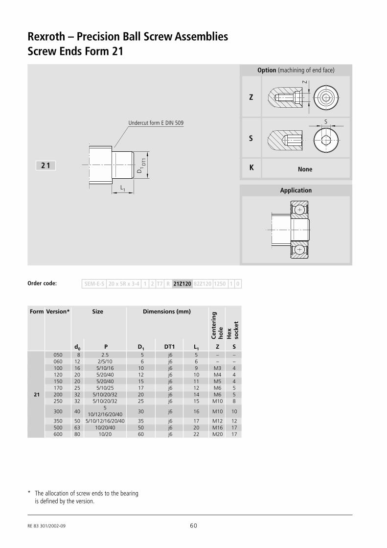
RE 83 301/2002-09 60
Rexroth – Precision Ball Screw Assemblies
Undercut form E DIN 509
Screw Ends Form 21
D1
DT1
L1
2 1
Form Version* Size Dimensions (mm)
d0 P D1 DT1 L1 Z S
Cen
teri
ng
ho
leH
exso
cket
Application
* The allocation of screw ends to the bearingis defined by the version.
Z
S
K
Z
S
None
Option (machining of end face)
SEM-E-S 20 x 5R x 3-4 1 2 T7 R 21Z120 82Z120 1250 1 0Order code:
050 8 2.5 5 j6 5 – –060 12 2/5/10 6 j6 6 – –100 16 5/10/16 10 j6 9 M3 4120 20 5/20/40 12 j6 10 M4 4150 20 5/20/40 15 j6 11 M5 4170 25 5/10/25 17 j6 12 M6 5
21 200 32 5/10/20/32 20 j6 14 M6 5250 32 5/10/20/32 25 j6 15 M10 8
300 405
30 j6 16 M10 1010/12/16/20/40350 50 5/10/12/16/20/40 35 j6 17 M12 12500 63 10/20/40 50 j6 20 M16 17600 80 10/20 60 j6 22 M20 17

61 RE 83 301/2002-09
Pillow block unit SEB-L Bearing LAD*
Form Version Size Pillow block Bearing LAD*unit SEB-L
d0 P Part number Part number
End Bearings for Screw Ends Form 21
050 8 2.5 1591-6-0500 1590-6-0500060 12 2/5/10 1591-6-0620 1590-6-0600100 16 5/10/16 1591-6-1020 1590-6-1000120 20 5/20/40 1591-6-1220 1590-6-1200150 20 5/20/40 – 1590-6-1500170 25 5/10/25 1591-6-1720 1590-6-1700
21 200 32 5/10/20/32 1591-6-2020 1590-6-2000250 32 5/10/20/32 – 1590-6-2500
300 405 1591-6-3020
1590-6-300010/12/16/20/40 1591-6-3010350 50 5/10/12/16/20/40 – 1590-6-3500500 63 10/20/40 – 1590-6-5000600 80 10/20 – 1590-6-6000
* Items delivered: 1 bearing, 2 retaining rings

RE 83 301/2002-09 62
Rexroth – Precision Ball Screw Assemblies
Undercut for retaining ring DIN 471 (3x)
Undercut form E DIN 509
Screw Ends Form 31
L5
L4 L4 LS1LST1
L1
S 1ST
1
D1
DT13 1
Form Version* Size Dimensions (mm)
d0 P D1 DT1 L1 L4 L5 S1 ST1 LS1 LST1 Z S
Cen
teri
ng
ho
le
Hex
sock
et
Application
* The allocation of screw ends to the bearingis defined by the version.Note: Form 31 with double movable bearing increases thecritical speed, see Page 116.
Z
S
K
Z
S
None
Option (machining of end face)
SEM-E-S 20 x 5R x 3-4 1 2 T7 R 31Z120 82Z120 1250 1 0Order code:
050 8 2.5 5 j6 22 5 20 4.8 h10 0.70 H13 – –060 12 2/5/10 6 j6 26 6 24 5.7 h10 0.80 H13 – –100 16 5/10/16 10 j6 39 9 36 9.6 h10 1.10 H13 M3 4120 20 5/20/40 12 j6 43 10 40 11.5 h11 1.10 H13 M4 4150 20 5/20/40 15 j6 47 11 44 14.3 h11 1.10 H13 M5 4170 25 5/10/25 17 j6 51 12 48 16.2 h11 1.10 H13 M6 531200 32 5/10/20/32 20 j6 60 14 56 19.0 h11 1.30 H13 M6 5250 32 5/10/20/32 25 j6 64 15 60 23.9 h12 1.30 H13 M10 8300 40 5/10/12/16/20/40 30 j6 68 16 64 28.6 h12 1.60 H13 M10 10350 50 5/10/12/16/20/40 35 j6 73 17 68 33.0 h12 1.60 H13 M12 12500 63 10/20/40 50 j6 87 20 80 47.0 h12 2.15 H13 M16 17600 80 10/20 60 j6 95 22 88 57.0 h12 2.15 H13 M20 17

63 RE 83 301/2002-09
End Bearings for Screw Ends Form 31
Form Version Size Pillow block Bearing LAD*unit SEC-L
d0 P Part number Part number
050 8 2.5 – 1590-6-0500060 12 2/5/10 – 1590-6-0600100 16 5/10/16 – 1590-6-1000120 20 5/20/40 – 1590-6-1200150 20 5/20/40 1594-6-1500 1590-6-1500
31170 25 5/10/25 – 1590-6-1700200 32 5/10/20/32 1594-6-2000 1590-6-2000250 32 5/10/20/32 – 1590-6-2500300 40 5/10/12/16/20/40 1594-6-3000 1590-6-3000350 50 5/10/12/16/20/40 – 1590-6-3500500 63 10/20/40 – 1590-6-5000600 80 10/20 – 1590-6-6000
* Items delivered: 1 bearing, 2 retaining rings.Two sets are required for applications with Form 31.
Pillow block unit SEC-L Bearing LAD*

RE 83 301/2002-09 64
Rexroth – Precision Ball Screw Assemblies
Undercut for retaining ring DIN 471
Undercut form E DIN 509
Screw Ends Form 41
L4 LS1LST1
D1
DT1
S 1ST
1
L1
4 1
Form Version* Size Dimensions (mm)
d0 P D1 DT1 L1 L4 S1 ST1 LS1 LST1 Z S
Cen
teri
ng
ho
le
Hex
sock
et
Application
* The allocation of screw ends to the bearingis defined by the version.
Z
S
K
Z
S
None
Option (machining of end face)
SEM-E-S 20 x 5R x 3-4 1 2 T7 R 41Z120 82Z120 1250 1 0Order code:
050 8 1/2/2.5 5 j6 7 5 4.8 h10 0.70 H13 – –060 12 2/5/10 6 j6 8 6 5.7 h10 0.80 H13 – –100 16 5/10/16 10 j6 12 9 9.6 h10 1.10 H13 M3 4120 20 5/20/40 12 j6 13 10 11.5 h11 1.10 H13 M4 4150 20 5/20/40 15 j6 14 11 14.3 h11 1.10 H13 M5 4170 25 5/10/25 17 j6 15 12 16.2 h11 1.10 H13 M6 5
41 200 32 5/10/20/32 20 j6 18 14 19.0 h11 1.30 H13 M6 5250 32 5/10/20/32 25 j6 19 15 23.9 h12 1.30 H13 M10 8
300 405
30 j6 20 16 28.6 h12 1.60 H13 M10 1010/12/16/20/40350 50 5/10/12/16/20/40 35 j6 22 17 33.0 h12 1.60 H13 M12 12500 63 10/20/40 50 j6 27 20 47.0 h12 2.15 H13 M16 17600 80 10/20 60 j6 29 22 57.0 h12 2.15 H13 M20 17

65 RE 83 301/2002-09
Pillow block unit SEB-L Bearing LAD*
End Bearings for Screw Ends Form 41
Form Version Size Bearing LAD* Pillow blockunit SEB-L
d0 P Part number Part number
* Items delivered: 1 bearing, 2 retaining rings
050 8 1/2/2.5 1590-6-0500 1591-6-0500060 12 2/5/10 1590-6-0600 1591-6-0620100 16 5/10/16 1590-6-1000 1591-6-1020120 20 5/20/40 1590-6-1200 1591-6-1220150 20 5/20/40 1590-6-1500 –170 25 5/10/25 1590-6-1700 1591-6-1720
41 200 32 5/10/20/32 1590-6-2000 1591-6-2020250 32 5/10/20/32 1590-6-2500 –
300 405
1590-6-30001591-6-3020
10/12/16/20/40 1591-6-3010350 50 5/10/12/16/20/40 1590-6-3500 –500 63 10/20/40 1590-6-5000 –600 80 10/20 1590-6-6000 –

RE 83 301/2002-09 66
Rexroth – Precision Ball Screw Assemblies
Thread undercut DIN 76 short
Undercut form F DIN 509
Screw Ends Form 51-53
max. 8 15 L
D1
DT1
L1 LG1G
1
∅12
friction-welded
5 1
5 3
Form Version* Size Dimensions (mm)
d0 P L D1 DT1 L1 G1 LG1 Z S
Cent
erin
gho
leH
exso
cket
Application
Z
S
K
Z
S
None
Option (machining of end face)
SEM-E-S 20 x 5R x 3-4 1 2 T7 R 51Z120 82Z120 1250 1 0Order code:
only 8 x 2.5
060 12 2/5/10 24 6 h6 14 M6x0.5 10 – –100 16 5/10/16 30 10 h6 18 M10x1 12 M3 4120 20 5/20/40 35 12 h6 23 M12x1 12 M4 4170 25 5/10/25 45 17 h6 23 M17x1 22 M5 5200 32 5/10/20/32 48 20 h6 26 M20x1 22 M6 5
51250 40 10/12/16/20/40 80 25 h6 54 M25x1.5 26 M8 8
300 405
51 30 h6 25 M30x1.5 26 M10 1010/12/16/20/40301 50 10/12/16/20/40 80 30 h6 54 M30x1.5 26 M10 10350 50 5 60 35 h6 32 M35x1.5 28 M12 12400 63 10/20/40 72 40 h6 44 M40x1.5 28 M16 12500 80 10/20 84 50 h6 52 M50x1.5 32 M16 17
53 060 8 2.5 24 6 h6 14 M6x0.5 10 – –
* The allocation of screw ends to the bearingis defined by the version.

67 RE 83 301/2002-09
Form Version Size Pillow block Bearing Slotted nut usedunit
SEB-F LAF LAN NMZ NMAd0 P Part number Part number Part number
Pillow block unit SEB-F Bearing LAN
End Bearings for Screw Ends Form 51-53
Bearing LAF
060 12 2/5/10 1591-1-0620 – 1590-1-0600 •100 16 5/10/16 1591-1-1020 – 1590-1-1000 •120 20 5/20/40 1591-1-1220 1590-0-1200 1590-1-1200 •170 25 5/10/25 1591-1-1730 1590-0-1730 1590-1-1730 •200 32 5/10/20/32 1591-1-2030 1590-0-2030 1590-1-2030 •
51250 40 10/12/16/20/40 1591-2-2530 1590-3-2530 1590-2-2530 •
300 405 1591-1-3030 1590-0-3030 1590-1-3030 •
10/12/16/20/40 – – – •301 50 10/12/16/20/40 – 1590-3-3030 1590-2-3030 •350 50 5 – 1590-0-3530 1590-1-3530 •400 63 10/20/40 – 1590-0-4030 1590-1-4030 •500 80 10/20 – 1590-0-5030 1590-1-5030 •
53 060 8 2.5 1591-1-0600 – 1590-1-0600 •

RE 83 301/2002-09 68
Rexroth – Precision Ball Screw Assemblies
5 1
Application
S
K
S
None
Option (machining of end face)
Screw Ends Form 51 for Driven Nut FAR-B-S
Liquid cooling of screwon request
D1
DT1
L1 LG1
G1
Undercut form DIN 609
Thread undercut DIN 76 short
L
d0 P L D1 DT1 L1 G1 LG1 S
209 32 10/20/32 108 20 h6 77 M20x1 31 8309 40 10/20/40 117 30 h6 83 M30x1.5 34 10359 50 10/20/40 145 35 h6 109 M35x1.5 36 12409 63 10/20/40 183 40 h6 147 M40x1.5 36 17
Form Size Dimensions [mm]
Hex
sock
et
51
Ver
sio
n
Order code: FAR-B-S 40 x 20R x 6-3 1 2 T5 R 51S309 51S309 3000 1 0
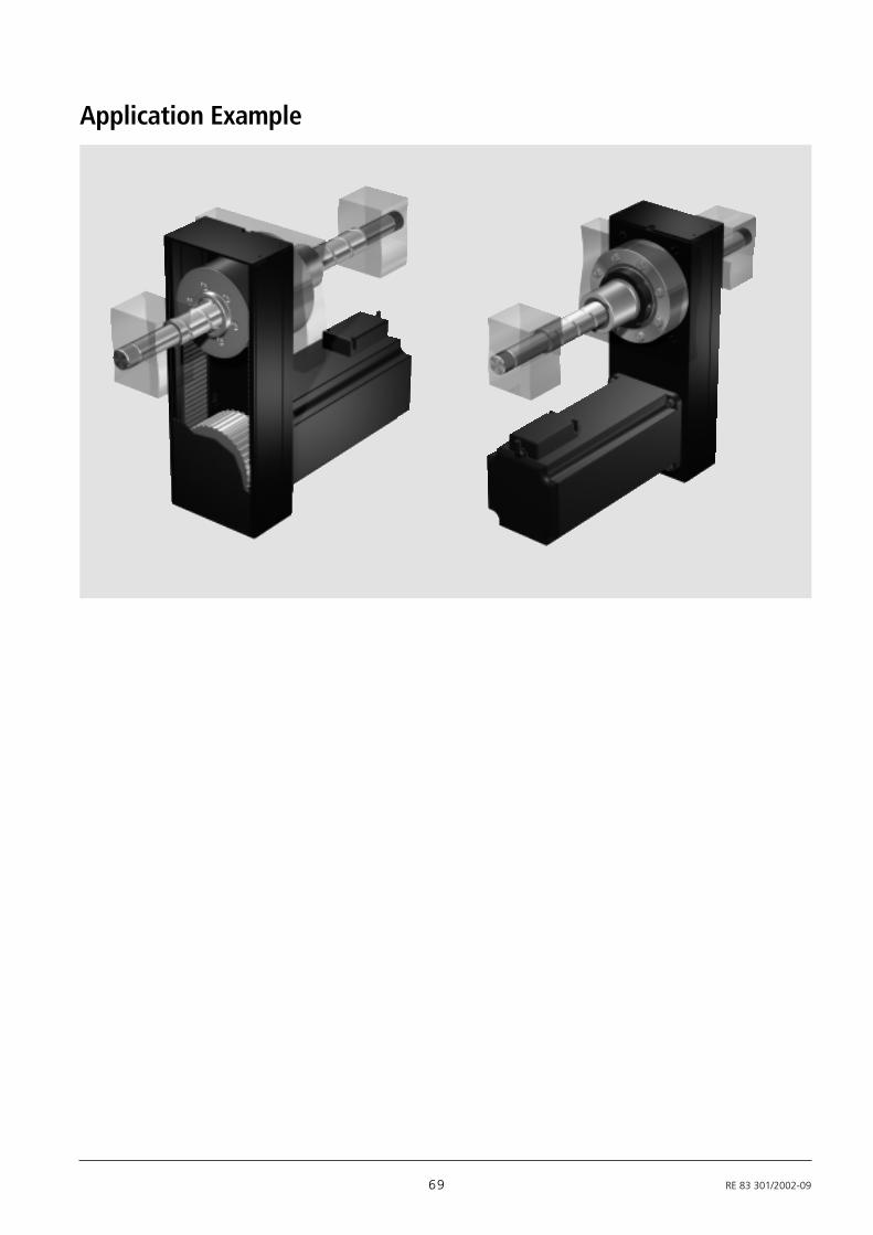
69 RE 83 301/2002-09
Application Example

RE 83 301/2002-09 70
Rexroth – Precision Ball Screw Assemblies
Undercut for retaining ring DIN 471 (3x)
Undercut form E DIN 509
Screw Ends Form 61-62
Undercut form E DIN 509
b x l x tbT
L5
L2
L4 L4 LS1LST1
L1
L
D1
DT1
S 1ST
1
D2
DT26 1
6 2
Form Ver- Size Dimensions (mm) Keyway sion* to DIN 6885
d0 P L D1 DT1 L1 D2 DT2 L2 L4 L5 S1 ST1 LS1 LST1 b bT l t Z SC
ente
rin
gh
ole
Hex
sock
et
Application
Z
S
K
Z
S
None
Option (machining of end face)
SEM-E-S 20 x 5R x 3-4 1 2 T7 R 62Z120 51Z120 1250 1 0Order code:
050 8 2.5 34 5 j6 22 4 h7 12 5 20 4.8 h10 0.70 H13 – –060 12 2/5/10 42 6 j6 26 5 h7 16 6 24 5.7 h10 0.80 H13 – –100 16 5/10/16 59 10 j6 39 8 h7 20 9 36 9.6 h10 1.10 H13 M3 –120 20 5/20/40 68 12 j6 43 10 h7 25 10 40 11.5 h11 1.10 H13 M3 4150 20 5/20/40 72 15 j6 47 12 h7 25 11 44 14.3 h11 1.10 H13 M4 4
61170 25 5/10/25 81 17 j6 51 15 h7 30 12 48 16.2 h11 1.10 H13 M5 4200 32 5/10/20/32 100 20 j6 60 18 h7 40 14 56 19.0 h11 1.30 H13 M6 5250 32 5/10/20/32 114 25 j6 64 22 h7 50 15 60 23.9 h12 1.30 H13 M8 6300 40 5/10/12/16/20/40 118 30 j6 68 28 h7 50 16 64 28.6 h12 1.60 H13 M10 10350 50 5/10/12/16/20/40 133 35 j6 73 32 h7 60 17 68 33.0 h12 1.60 H13 M12 10500 63 10/20/40 167 50 j6 87 48 h7 80 20 80 47.0 h12 2.15 H13 M16 17600 80 10/20 175 60 j6 95 58 h7 80 22 88 57.0 h12 2.15 H13 M20 17100 16 5/10/16 59 10 j6 39 8 h7 20 9 36 9.6 h10 1.10 H13 2 P9 14 1.2 M3 –120 20 5/20/40 68 12 j6 43 10 h7 25 10 40 11.5 h11 1.10 H13 3 P9 20 1.8 M3 4150 20 5/20/40 72 15 j6 47 12 h7 25 11 44 14.3 h11 1.10 H13 4 P9 20 2.5 M4 4170 25 5/10/25 81 17 j6 51 15 h7 30 12 48 16.2 h11 1.10 H13 5 P9 25 3 M5 4
62200 32 5/10/20/32 100 20 j6 60 18 h7 40 14 56 19.0 h11 1.30 H13 6 P9 28 3.5 M6 5250 32 5/10/20/32 114 25 j6 64 22 h7 50 15 60 23.9 h12 1.30 H13 6 P9 36 3.5 M8 6300 40 5/10/12/16/20/40 118 30 j6 68 28 h7 50 16 64 28.6 h12 1.60 H13 8 P9 36 4 M10 10350 50 5/10/12/16/20/40 133 35 j6 73 32 h7 60 17 68 33.0 h12 1.60 H13 10 P9 40 5 M12 10500 63 10/20/40 167 50 j6 87 48 h7 80 20 80 47.0 h12 2.15 H13 14 P9 63 5.5 M16 17600 80 10/20 175 60 j6 95 58 h7 80 22 88 57.0 h12 2.15 H13 16 P9 63 6 M20 17
* The allocation of screw ends to the bearingis defined by the version.

71 RE 83 301/2002-09
Form Version Size Bearing LAD*
d0 P Part number
End Bearings for Screw Ends Form 61-62
Bearing LAD*
050 8 2.5 1590-6-0500060 12 2/5/10 1590-6-0600100 16 5/10/16 1590-6-1000120 20 5/20/40 1590-6-1200150 20 5/20/40 1590-6-1500
61170 25 5/10/25 1590-6-1700200 32 5/10/20/32 1590-6-2000250 32 5/10/20/32 1590-6-2500300 40 5/10/12/16/20/40 1590-6-3000350 50 5/10/12/16/20/40 1590-6-3500500 63 10/20/40 1590-6-5000600 80 10/20 1590-6-6000100 16 5/10/16 1590-6-1000120 20 5/20 1590-6-1200150 20 5/20 1590-6-1500170 25 5/10/25 1590-6-1700
62200 32 5/10/20/32 1590-6-2000250 32 5/10/20/32 1590-6-2500300 40 5/10/12/16/20/40 1590-6-3000350 50 5/10/12/16/20/40 1590-6-3500500 63 10/20/40 1590-6-5000600 80 10/20 1590-6-6000
* Items delivered: 1 bearing, 2 retaining rings.Two sets are required for applications with Form 61-62.

RE 83 301/2002-09 72
Rexroth – Precision Ball Screw Assemblies
Form Version* Size Dimensions (mm) Keywayto DIN 6885
d0 P L D1 DT1 L1 D2 DT2 L2 L4 S1 ST1 LS1 LST1 b bT l t Z S
Undercut for retaining ring DIN 471
Undercut form E DIN 509
Screw End Form 71-72
D1
DT1
b x l x tbT
1L L2
L4 LS1LST1
L
S 1ST
1
D2
DT2
7 1
Undercut form E DIN 509
7 2
Cen
teri
ng
ho
leH
exso
cket
Application
Z
S
K
Z
S
None
Option (machining of end face)
SEM-E-S 20 x 5R x 3-4 1 2 T7 R 72Z120 51Z120 1250 1 0Order code:
050 8 2.5 19 5 j6 7 4 h7 12 5 4.8 h10 0.70 H13 – –060 12 2/5/10 24 6 j6 8 5 h7 16 6 5.7 h10 0.80 H13 – –100 16 5/10/16 32 10 j6 12 8 h7 20 9 9.6 h10 1.10 H13 M3 –120 20 5/20/40 38 12 j6 13 10 h7 25 10 11.5 h11 1.10 H13 M3 4150 20 5/20/40 39 15 j6 14 12 h7 25 11 14.3 h11 1.10 H13 M4 4
71170 25 5/10/25 45 17 j6 15 15 h7 30 12 16.2 h11 1.10 H13 M5 4200 32 5/10/20/32 58 20 j6 18 18 h7 40 14 19.0 h11 1.30 H13 M6 5250 32 5/10/20/32 69 25 j6 19 22 h7 50 15 23.9 h12 1.30 H13 M8 6300 40 5/10/12/16/20/40 70 30 j6 20 28 h7 50 16 28.6 h12 1.60 H13 M10 10350 50 5/10/12/16/20/40 82 35 j6 22 32 h7 60 17 33.0 h12 1.60 H13 M12 10500 63 10/20/40 107 50 j6 27 48 h7 80 20 47.0 h12 2.15 H13 M16 17600 80 10/20 109 60 j6 29 58 h7 80 22 57.0 h12 2.15 H13 M20 17100 16 5/10/16 32 10 j6 12 8 h7 20 9 9.6 h10 1.10 H13 2 P9 14 1.2 M3 –120 20 5/20/40 38 12 j6 13 10 h7 25 10 11.5 h11 1.10 H13 3 P9 20 1.8 M3 4150 20 5/20/40 39 15 j6 14 12 h7 25 11 14.3 h11 1.10 H13 4 P9 20 2.5 M4 4170 25 5/10/25 45 17 j6 15 15 h7 30 12 16.2 h11 1.10 H13 5 P9 25 3 M5 4
72200 32 5/10/20/32 58 20 j6 18 18 h7 40 14 19.0 h11 1.30 H13 6 P9 28 3.5 M6 5250 32 5/10/20/32 69 25 j6 19 22 h7 50 15 23.9 h12 1.30 H13 6 P9 36 3.5 M8 6300 40 5/10/12/16/20/40 70 30 j6 20 28 h7 50 16 28.6 h12 1.60 H13 8 P9 36 4 M10 10350 50 5/10/12/16/20/40 82 35 j6 22 32 h7 60 17 33.0 h12 1.60 H13 10 P9 40 5 M12 10500 63 10/20/40 107 50 j6 27 48 h7 80 20 47.0 h12 2.15 H13 14 P9 63 5.5 M16 17600 80 10/20 109 60 j6 29 58 h7 80 22 57.0 h12 2.15 H13 16 P9 63 6 M20 17
* The allocation of screw ends to the bearingis defined by the version.

73 RE 83 301/2002-09
End Bearings for Screw Ends Form 71-72
Bearing LAD*
Form Version Size Bearing LAD*
d0 P Part number050 8 2.5 1590-6-0500060 12 2/5/10 1590-6-0600100 16 5/10/16 1590-6-1000120 20 5/20/40 1590-6-1200150 20 5/20/40 1590-6-1500
71170 25 5/10/25 1590-6-1700200 32 5/10/20/32 1590-6-2000250 32 5/10/20/32 1590-6-2500300 40 5/10/12/16/20/40 1590-6-3000350 50 5/10/12/16/20/40 1590-6-3500500 63 10/20/40 1590-6-5000600 80 10/20 1590-6-6000100 16 5/10/16 1590-6-1000120 20 5/20/40 1590-6-1200150 20 5/20/40 1590-6-1500170 25 5/10/25 1590-6-1700
72200 32 5/10/20/32 1590-6-2000250 32 5/10/20/32 1590-6-2500300 40 5/10/12/16/20/40 1590-6-3000350 50 5/10/12/16/20/40 1590-6-3500500 63 10/20/40 1590-6-5000600 80 10/20 1590-6-6000
* Items delivered: 1 bearing, 2 retaining rings

RE 83 301/2002-09 74
Rexroth – Precision Ball Screw Assemblies
G1
b x l x tbT
max. 8 15 L
∅12
D2
L1 1LG L2
L
DT2
DT1
D1
Thread undercut DIN 76 short
Undercut form E DIN 509
Undercut form F DIN 509
Screw Ends Form 81-82-83
friction-welded
8 1
Form Version* Size Dimensions (mm) Keywayto DIN 6885
d0 P L D1 DT1 L 1 D2 DT2 L 2 G1 LG1 b bT l t Z SC
ente
rin
gh
ole
Hex
sock
et
8 2
8 3
Z
S
K
Z
S
None
Option (machining of end face)
Application
SEM-E-S 20 x 5R x 3-4 1 2 T7 R 82Z120 41Z120 1250 1 0Order code:
060 12 2/5/10 40 6 h6 14 5 h7 16 M6x0.5 10 – –100 16 5/10/16 50 10 h6 18 8 h7 20 M10x1 12 M3 –120 20 5/20/40 60 12 h6 23 10 h7 25 M12x1 12 M3 4170 25 5/10/25 75 17 h6 23 15 h7 30 M17x1 22 M5 4200 32 5/10/20/32 88 20 h6 26 18 h7 40 M20x1 22 M6 5
81203 32 5/10/20/32 78 20 h6 26 16 h7 35 M20x1 17 M5 4250 40 10/12/16/20/40 130 25 h6 54 22 h7 50 M25x1.5 26 M8 6
300 405
101 30 h6 25 25 h7 50 M30x1.5 26 M10 810/12/16/20/40301 40 5/10/12/16/20/40 93 30 h6 25 25 h7 50 M30x1.5 18 M10 8302 50 10/12/16/20/40 130 30 h6 54 25 h7 50 M30x1.5 26 M10 8350 50 5 110 35 h6 32 30 h7 50 M35x1.5 28 M10 10400 63 10/20/40 132 40 h6 44 36 h7 60 M40x1.5 28 M12 12500 80 10/20 154 50 h6 52 40 h7 70 M50x1.5 32 M16 12100 16 5/10/16 50 10 h6 18 8 h7 20 M10x1 12 2 P9 14 1.2 M3 –120 20 5/20/40 60 12 h6 23 10 h7 25 M12x1 12 3 P9 20 1.8 M3 4170 25 5/10/25 75 17 h6 23 15 h7 30 M17x1 22 5 P9 25 3 M5 4200 32 5/10/20/32 88 20 h6 26 18 h7 40 M20x1 22 6 P9 28 3.5 M6 5203 32 5/10/20/32 78 20 h6 26 16 h7 35 M20x1 17 5 P9 28 3 M5 4250 40 10/12/16/20/40 130 25 h6 54 22 h7 50 M25x1.5 26 6 P9 36 3.5 M8 682300 40
5101 30 h6 25 25 h7 50 M30x1.5 26 8 P9 36 4 M10 810/12/16/20/40
301 40 5/10/12/16/20/40 93 30 h6 25 25 h7 50 M30x1.5 18 8 P9 36 4 M10 8302 50 10/12/16/20/40 130 30 h6 54 25 h7 50 M30x1.5 26 8 P9 36 4 M10 8350 50 5 110 35 h6 32 30 h7 50 M35x1.5 28 8 P9 36 4 M10 10400 63 10/20/40 132 40 h6 44 36 h7 60 M40x1.5 28 10 P9 40 5 M12 12500 80 10/20 154 50 h6 52 40 h7 70 M50x1.5 32 12 P9 50 5 M16 12
83060 6 1/2 40 6 h6 14 5 h7 16 M6x0.5 10 – –060 8 1/2/2.5 40 6 h6 14 5 h7 16 M6x0.5 10 – –
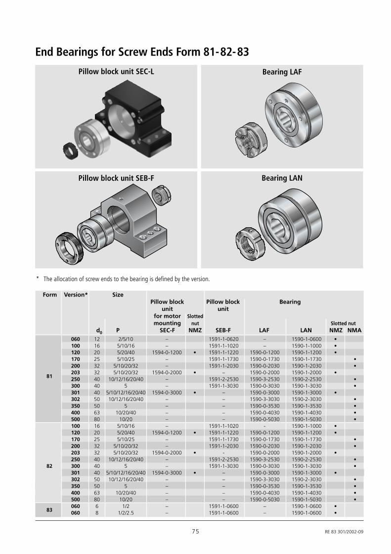
75 RE 83 301/2002-09
Form Version* SizePillow block Pillow block Bearing
unit unitfor motor Slottedmounting nut Slotted nut
d0 P SEC-F NMZ SEB-F LAF LAN NMZ NMA
Pillow block unit SEB-F Bearing LAN
Pillow block unit SEC-L
End Bearings for Screw Ends Form 81-82-83
Bearing LAF
060 12 2/5/10 – 1591-1-0620 – 1590-1-0600 •100 16 5/10/16 – 1591-1-1020 – 1590-1-1000 •120 20 5/20/40 1594-0-1200 • 1591-1-1220 1590-0-1200 1590-1-1200 •170 25 5/10/25 – 1591-1-1730 1590-0-1730 1590-1-1730 •200 32 5/10/20/32 – 1591-1-2030 1590-0-2030 1590-1-2030 •
81203 32 5/10/20/32 1594-0-2000 • – 1590-0-2000 1590-1-2000 •250 40 10/12/16/20/40 – 1591-2-2530 1590-3-2530 1590-2-2530 •300 40 5 – 1591-1-3030 1590-0-3030 1590-1-3030 •301 40 5/10/12/16/20/40 1594-0-3000 • – 1590-0-3000 1590-1-3000 •302 50 10/12/16/20/40 – – 1590-3-3030 1590-2-3030 •350 50 5 – – 1590-0-3530 1590-1-3530 •400 63 10/20/40 – – 1590-0-4030 1590-1-4030 •500 80 10/20 – – 1590-0-5030 1590-1-5030 •100 16 5/10/16 – 1591-1-1020 - 1590-1-1000 •120 20 5/20/40 1594-0-1200 • 1591-1-1220 1590-0-1200 1590-1-1200 •170 25 5/10/25 – 1591-1-1730 1590-0-1730 1590-1-1730 •200 32 5/10/20/32 – 1591-1-2030 1590-0-2030 1590-1-2030 •203 32 5/10/20/32 1594-0-2000 • - 1590-0-2000 1590-1-2000 •250 40 10/12/16/20/40 – 1591-2-2530 1590-3-2530 1590-2-2530 •
82 300 40 5 – 1591-1-3030 1590-0-3030 1590-1-3030 •301 40 5/10/12/16/20/40 1594-0-3000 • – 1590-0-3000 1590-1-3000 •302 50 10/12/16/20/40 – – 1590-3-3030 1590-2-3030 •350 50 5 – – 1590-0-3530 1590-1-3530 •400 63 10/20/40 – – 1590-0-4030 1590-1-4030 •500 80 10/20 – – 1590-0-5030 1590-1-5030 •
83060 6 1/2 – 1591-1-0600 – 1590-1-0600 •060 8 1/2/2.5 – 1591-1-0600 – 1590-1-0600 •
* The allocation of screw ends to the bearing is defined by the version.
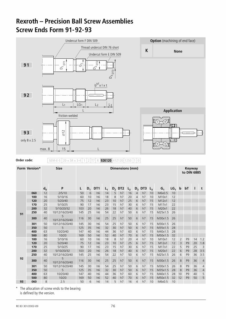
RE 83 301/2002-09 76
Rexroth – Precision Ball Screw Assemblies
Thread undercut DIN 76 short
Undercut form E DIN 509
G1
b x l x tbT
max. 8 15 L
L1 1LG L2 L3
L
D1
DT1
D2
DT2
D3
DT3
∅12
Undercut form F DIN 509
Screw Ends Form 91-92-93
friction-welded
9 1
9 2
9 3
Application
SEM-E-S 20 x 5R x 3-4 1 2 T7 R 92K120 41Z120 1250 1 0Order code:
only 8 x 2.5
K None
Option (machining of end face)
Form Version* Size Dimensions (mm) Keywayto DIN 6885
d0 P L D1 DT1 L1 D2 DT2 L2 D3 DT3 L3 G1 LG1 b bT l t060 12 2/5/10 50 6 h6 14 5 h7 16 4 h7 10 M6x0.5 10100 16 5/10/16 60 10 h6 18 8 h7 20 4 h7 10 M10x1 12120 20 5/20/40 75 12 h6 23 10 h7 25 6 h7 15 M12x1 12170 25 5/10/25 90 17 h6 23 15 h7 30 6 h7 15 M17x1 22200 32 5/10/20/32 103 20 h6 26 18 h7 40 6 h7 15 M20x1 22250 40 10/12/16/20/40 145 25 h6 54 22 h7 50 6 h7 15 M25x1.5 2691300 40
5116 30 h6 25 25 h7 50 6 h7 15 M30x1.5 2610/12/16/20/40
301 50 10/12/16/20/40 145 30 h6 54 25 h7 50 6 h7 15 M30x1.5 26350 50 5 125 35 h6 32 30 h7 50 6 h7 15 M35x1.5 28400 63 10/20/40 147 40 h6 44 36 h7 60 6 h7 15 M40x1.5 28500 80 10/20 169 50 h6 52 40 h7 70 6 h7 15 M50x1.5 32100 16 5/10/16 60 10 h6 18 8 h7 20 4 h7 10 M10x1 12 2 P9 14 1.2120 20 5/20/40 75 12 h6 23 10 h7 25 6 h7 15 M12x1 12 3 P9 20 1.8170 25 5/10/25 90 17 h6 23 15 h7 30 6 h7 15 M17x1 22 5 P9 25 3200 32 5/10/20/32 103 20 h6 26 18 h7 40 6 h7 15 M20x1 22 6 P9 28 3.5250 40 10/12/16/20/40 145 25 h6 54 22 h7 50 6 h7 15 M25x1.5 26 6 P9 36 3.5
92300 40
5116 30 h6 25 25 h7 50 6 h7 15 M30x1.5 26 8 P9 36 410/12/16/20/40
301 50 10/12/16/20/40 145 30 h6 54 25 h7 50 6 h7 15 M30x1.5 26 8 P9 36 4350 50 5 125 35 h6 32 30 h7 50 6 h7 15 M35x1.5 28 8 P9 36 4400 63 10/20/40 147 40 h6 44 36 h7 60 6 h7 15 M40x1.5 28 10 P9 40 5500 80 10/20 169 50 h6 52 40 h7 70 6 h7 15 M50x1.5 32 12 P9 50 5
93 060 8 2.5 50 6 h6 14 5 h7 16 4 h7 10 M6x0.5 10
* The allocation of screw ends to the bearingis defined by the version.

77 RE 83 301/2002-09
Pillow Block Unit SEB-F Bearing LAN
End Bearings for Screw Ends Form 91-92-93
Bearing LAF
Form Version Size Pillow block Bearing Slotted nut usedunit
SEB-F LAF LAN NMZ NMAd0 P Part number Part number Part number
060 12 2/5/10 1591-1-0620 – 1590-1-0600 •100 16 5/10/16 1591-1-1020 – 1590-1-1000 •120 20 5/20/40 1591-1-1220 1590-0-1200 1590-1-1200 •170 25 5/10/25 1591-1-1730 1590-0-1730 1590-1-1730 •200 32 5/10/20/32 1591-1-2030 1590-0-2030 1590-1-2030 •
91250 40 10/12/16/20/40 1591-2-2530 1590-3-2530 1590-2-2530 •
300 405 1591-1-3030 1590-0-3030 1590-1-3030 •
10/12/16/20/40 – – – •301 50 10/12/16/20/40 – 1590-3-3030 1590-2-3030 •350 50 5 – 1590-0-3530 1590-1-3530 •400 63 10/20/40 – 1590-0-4030 1590-1-4030 •500 80 10/20 – 1590-0-5030 1590-1-5030 •100 16 5/10/16 1591-1-1020 – 1590-1-1000 •120 20 5/20/40 1591-1-1220 1590-0-1200 1590-1-1200 •170 25 5/10/25 1591-1-1730 1590-0-1730 1590-1-1730 •200 32 5/10/20/32 1591-1-2030 1590-0-2030 1590-1-2030 •250 40 10/12/16/20/40 1591-2-2530 1590-3-2530 1590-2-2530 •
92300 40
5 1591-1-3030 1590-0-3030 1590-1-3030 •10/12/16/20/40 – – – •
301 50 10/12/16/20/40 – 1590-3-3030 1590-2-3030 •350 50 5 – 1590-0-3530 1590-1-3530 •400 63 10/20/40 – 1590-0-4030 1590-1-4030 •500 80 10/20 – 1590-0-5030 1590-1-5030 •
93 060 8 2.5 1591-1-0600 1590-1-0600 •
Shown withslotted nutNMZ
Shown withslotted nutNMA

RE 83 301/2002-09 78
Rexroth – Precision Ball Screw Assemblies
81
82
Fixed bearing withangular-contact thrust ballbearingLGF-B-…
The pillow block unit consists of:– precision pillow block housing made of
aluminium with reference edges on twosides
– angular-contact thrust ball bearingLGF...
– slotted nut NMZ
The nut is delivered unmounted.
Pillow Block Unit SEC-F
Screw end form 81/82 suitable for motormounting, see Pages 74/75
20x5/20/40 1594-0-1200 17000 24700 12 55 25 LGF-B-1255 8.0 NMZ 12x1 1.4932x5/10/20/32 1594-0-2000 26000 47000 20 68 28 LGF-B-2068 18.0 NMZ 20x1 1.8840x5/10/12/16/20/40 1594-0-3000 29000 64000 30 80 28 LGF-B-3080 32.0 NMZ 30x1.5 2.75
Size Pillow block unit Angular-contact thrust ball bearing Slotted nut WeightPart number Load ratings (axial) Dimensions Designation MA Designation complete
dyn. stat. (mm)d0 x P complete C C0 d D B
(N) (N) (Nm) (kg)

79 RE 83 301/2002-09
B
L
B
D
L
B
d
L
LL
DD 224
L22 3
2
20
1
11
2B3
B4
M3
S2S1
M2
3 3S Tx
V 2H
4
V1M1
2xM1
H3
1HH
2
Centering diameter D
for motor flange
Fastening thread S3 x T3
for motor flange
60 10 40 20 42 42 15 18 60 25 55 10 72.5 80 120 41 81 28 10 10.5 9.7 M8 20 66 5060 10 40 20 40 38 18 20 78 35 68 16 72.5 103 120 46 91 28 10 10.5 9.7 M8 20 90 466512.5 40 20 45 45 20 20 93 50 80 25 90 116 150 56 111 33 10 13 11.7 M10 20 100 65
Dimensions (mm)
B1 B2 B3 B4 L1 L2 L3 L4 L20 L22 D1 D22 M1 M2 M3 H1 H2 H3 H4 S1 S2 S3 T3 V1 V2
±0.015 ±0.015
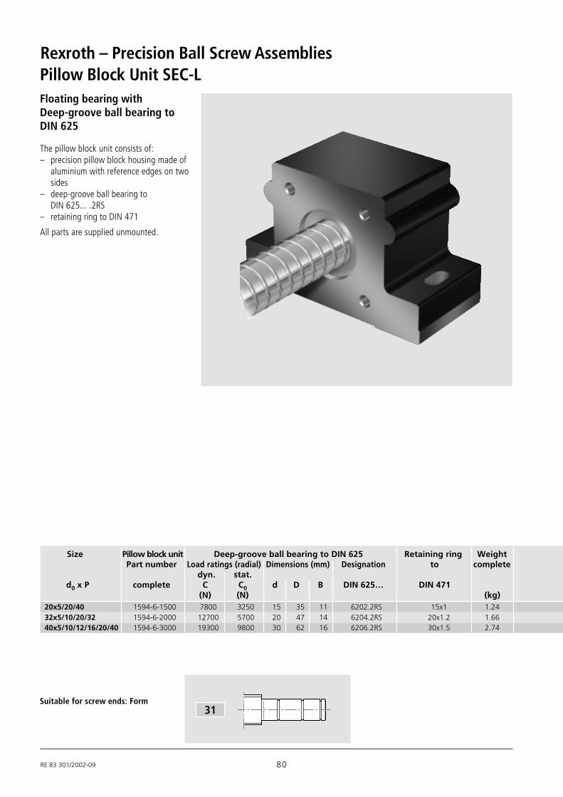
RE 83 301/2002-09 80
Rexroth – Precision Ball Screw Assemblies
Suitable for screw ends: Form
Floating bearing withDeep-groove ball bearing toDIN 625
The pillow block unit consists of:– precision pillow block housing made of
aluminium with reference edges on twosides
– deep-groove ball bearing toDIN 625... .2RS
– retaining ring to DIN 471
All parts are supplied unmounted.
Pillow Block Unit SEC-L
31
20x5/20/40 1594-6-1500 7800 3250 15 35 11 6202.2RS 15x1 1.2432x5/10/20/32 1594-6-2000 12700 5700 20 47 14 6204.2RS 20x1.2 1.6640x5/10/12/16/20/40 1594-6-3000 19300 9800 30 62 16 6206.2RS 30x1.5 2.74
Size Pillow block unit Deep-groove ball bearing to DIN 625 Retaining ring WeightPart number Load ratings (radial) Dimensions (mm) Designation to complete
dyn. stat.d0 x P complete C C0 d D B DIN 625… DIN 471
(N) (N) (kg)
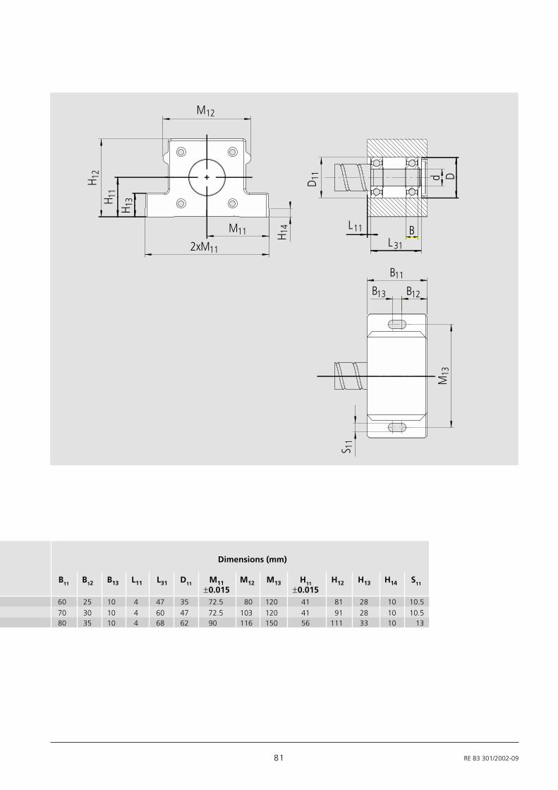
81 RE 83 301/2002-09
M12
H 12
H 11
H 13
2xM11
M11 H 14
D 11
L11
L31
B
d D
B
B11
13 B12
M13
S 11
60 25 10 4 47 35 72.5 80 120 41 81 28 10 10.5
70 30 10 4 60 47 72.5 103 120 41 91 28 10 10.580 35 10 4 68 62 90 116 150 56 111 33 10 13
Dimensions (mm)
B11 B12 B13 L11 L31 D11 M11 M12 M13 H11 H12 H13 H14 S11
±0.015 ±0.015

RE 83 301/2002-09 82
Rexroth – Precision Ball Screw Assemblies
51
81
82
91
92
Suitable for screw ends: FormFor screws 8 x 1/2/2.5: Form 53, 83, 93
Fixed bearing with angular-contact thrust ball bearingLGN-B-…LGN-C-…
The pillow block unit consists of:– precision pillow block housing with
reference edges on two sides– angular-contact thrust ball bearing LGN– slotted nut NMA or NMZ– housing nut GR
The nut is delivered unmounted.
Pillow Block Unit SEB-F
Size Pillow block unit Angular-contact thrust ball bearing Slotted nut WeightPart number Load ratings (axial) Dimensions (mm) Designation MA Designation complete
dyn. stat.d0 x P complete C C0 d D B
(N) (N) (Nm) (kg)
6x1/2 1591-1-0600 6900 8500 6 24 15 LGN-B-0624 2.0 NMZ 6x0.5 0.388x1/2/2.5 1591-1-0600 6900 8500 6 24 15 LGN-B-0624 2.0 NMZ 6x0.5 0.3812x2/5/10 1591-1-0620 6900 8500 6 24 15 LGN-B-0624 2.0 NMZ 6x0.5 0.3816x5 16x10 16x16 1591-1-1020 13400 18800 10 34 20 LGN-B-1043 6.0 NMZ 10x1 0.8720x5/20/40 1591-1-1220 17000 24700 12 42 25 LGN-B-1242 8.0 NMZ 12x1 1.12
25x5/10/251591-1-1720
18800 31000 17 47 25 LGN-B-1747 15.0NMZ 17x1 1.65
1591-1-1730 NMA 17x1 1.69
32x5/10/20/321591-1-2020
26000 47000 20 52 28 LGN-B-2052 18.0 NMZ 20x1 1.93
1591-1-2030 NMA 20x1 2.0340x10/12/16/20/40 1591-2-2530 44500 111000 25 57 56 LGN-C-2557 25.0 NMA 25x1.5 5.13
40x51591-1-3020
29000 64000 30 62 28 LGN-B-3062 32.0 NMZ 30x1.5 2.64
1591-1-3030 NMA 30x1.5 2.77
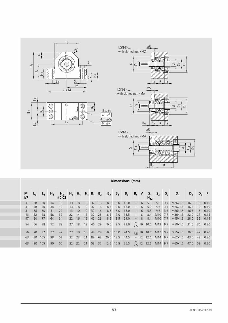
83 RE 83 301/2002-09
∅P
∅5
D d
B B3B3
∅5D d
BB3
V2 x M
45°
3L
M
∅P
H1
H2
H3
H4
1S
2S3S
H5
B1
B4
B2
B4
B5
L 44 x S /S21
2 x S3
D1
D2
D3
∅5
D d
B B3B3
D1
B6
D3
D2
D3
D2
D1
Dimensions (mm)
M L3 L4 H1 H2 H3 H4 H5 B1 B2 B3 B4 B5 B6 V S1 S2 S3 D1 D2 D3 Pjs7 ±0.02 H12
LGN-B-…with slotted nut NMZ
LGN-B-…with slotted nut NMA
LGN-C-…with slotted nut NMA
31 38 50 34 18 13 8 9 32 16 8.5 8.0 16.0 – 6 5.3 M6 3.7 M26x1.5 16.5 18 0.1031 38 50 34 18 13 8 9 32 16 8.5 8.0 16.0 – 6 5.3 M6 3.7 M26x1.5 16.5 18 0.1031 38 50 41 22 13 10 9 32 16 8.5 8.0 16.0 – 6 5.3 M6 3.7 M26x1.5 16.5 18 0.1043 52 68 58 32 22 14 15 37 23 8.5 7.0 18.5 – 8 8.4 M10 7.7 M36x1.5 22.0 27 0.1547 60 77 64 34 22 16 15 42 25 8.5 8.5 21.0 – 8 8.4 M10 7.7 M45x1.5 28.0 32 0.15
54 66 88 72 39 27 18 18 46 29 10.5 8.5 23.0–
10 10.5 M12 9.7 M50x1.5 31.0 36 0.207.5
56 70 92 77 42 27 19 18 49 29 10.5 10.0 24.5–
10 10.5 M12 9.7 M55x1.5 36.0 42 0.207.563 80 105 98 58 32 23 21 89 62 20.5 13.5 44.5 – 12 12.6 M14 9.7 M62x1.5 43.0 48 0.20
63 80 105 90 50 32 22 21 53 32 12.5 10.5 26.5–
12 12.6 M14 9.7 M65x1.5 47.0 53 0.207.5

RE 83 301/2002-09 84
Rexroth – Precision Ball Screw Assemblies
21
Suitable for screw ends: FormFor screws 12 x 2: Form 41
Floating bearing withDeep-groove ball bearing toDIN 625
The pillow block unit consists of:– precision pillow block housing with
reference edge on one side– deep-groove ball bearing to
DIN 625-... 2RS– retaining ring to DIN 471– cover
All parts are supplied unmounted.
Pillow Block Unit SEB-L
8x1/2/2.5 1591-6-0500 1900 590 5 16 5 625.2RS 5x0.6 0.1412x2/5/10 1591-6-0620 2450 900 6 19 6 626.2RS 6x0.7 0.1816x5/10/16 1591-6-1020 6000 2240 10 30 9 6200.2RS 10x1 0.5420x5/20/40 1591-6-1220 6950 2650 12 32 10 6201.2RS 12x1 0.7325x5/10/25 1591-6-1720 9500 4150 17 40 12 6203.2RS 17x1 0.9632x5/10/20/32 1591-6-2020 12700 5700 20 47 14 6204.2RS 20x1.2 1.2440x5 1591-6-3020 19300 9800 30 62 16 6206.2RS 30x1.5 1.6640x10/12/16/20/40 1591-6-3010 19300 9800 30 62 16 6206.2RS 30x1.5 1.82
Size Pillow block unit Deep-groove ball bearing to DIN 625 Retaining ring WeightPart number Load ratings (radial) Dimensions (mm) Designation Designation complete
dyn. stat.d0 x P complete C C0 d D B DIN 625… DIN 471
(N) (N) (kg)
41
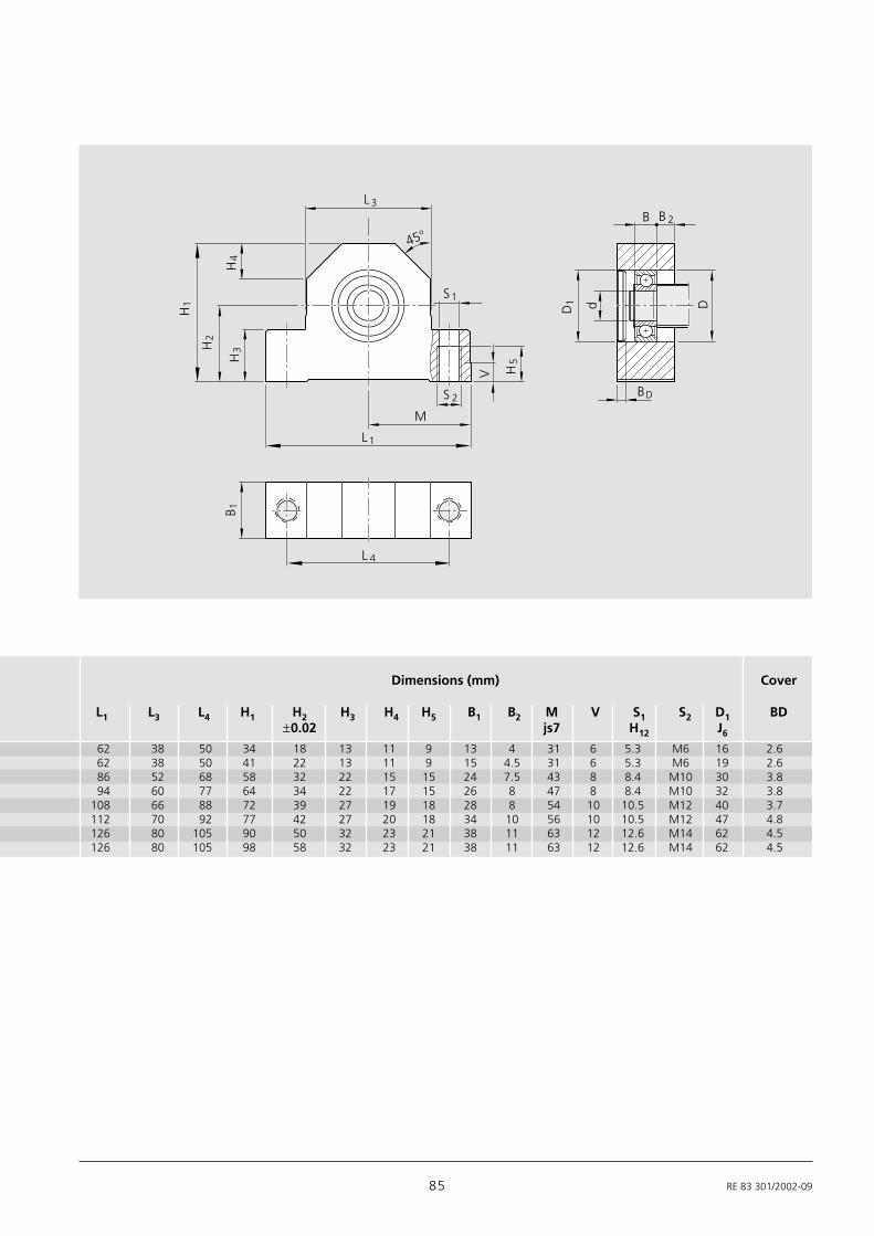
85 RE 83 301/2002-09
L 4
V
2S
M
3L
1S
45°B
d D
BD
B
H5
1L
H1
H4
H2
H3
B 12
D1
Dimensions (mm) Cover
L1 L3 L4 H1 H2 H3 H4 H5 B1 B2 M V S1 S2 D1 BD±0.02 js7 H12 J6
62 38 50 34 18 13 11 9 13 4 31 6 5.3 M6 16 2.662 38 50 41 22 13 11 9 15 4.5 31 6 5.3 M6 19 2.686 52 68 58 32 22 15 15 24 7.5 43 8 8.4 M10 30 3.894 60 77 64 34 22 17 15 26 8 47 8 8.4 M10 32 3.8
108 66 88 72 39 27 19 18 28 8 54 10 10.5 M12 40 3.7112 70 92 77 42 27 20 18 34 10 56 10 10.5 M12 47 4.8126 80 105 90 50 32 23 21 38 11 63 12 12.6 M14 62 4.5126 80 105 98 58 32 23 21 38 11 63 12 12.6 M14 62 4.5

RE 83 301/2002-09 86
Rexroth – Precision Ball Screw Assemblies
Suitable for screw ends: Form
51
81
82
11
12
92
91
Fixed bearing with angular-contact thrust ball bearingLGF
The fixed bearing consists of:– angular-contact thrust ball bearing LGF– slotted nut NMA..., NMZ...
Double-thrust, screw-down,
Bearing LAF
Size Angular- Single parts Load ratingscontact thrustball bearing Angular-contact
with slotted nut thrust ball bearing Slotted nut dyn. stat.
d0 x P Part number Designation Part number Designation Part number C C0(N) (N)
20x5/20/40 1590-0-1200 LGF-B-1255 8414-009-06 NMZ 12x1 8446-003-04 17000 24700
25x5/10/251590-0-1700
LGF-B-1762 8414-010-06NMZ 17x1 8446-004-04
18800 310001590-0-1730 NMA 17x1 8446-014-04
32x5/10/20/321590-0-2000
LGF-B-2068 8414-001-06NMZ 20x1 8446-005-04
26000 470001590-0-2030 NMA 20x1 8446-015-04
40x51590-0-3000
LGF-B-3080 8414-011-06NMZ 30x1.5 8446-006-04
29000 640001590-0-3030 NMA 30x1.5 8446-016-0440x10/12/16/20/40 1590-3-2530 LGF-C-2575 8414-015-06 NMA 25x1.5 8446-011-04 44500 11100050x5 1590-0-3530 LGF-B-3590 8414-026-06 NMA 35x1.5 8446-012-04 41000 8900050x10/12/16/20/40 1590-3-3030 LGF-C-3080 8414-027-06 NMA 30x1.5 8446-016-04 47500 12700063x10/20/40 1590-0-4030 LGF-B-40115 8414-028-06 NMA 40x1.5 8446-018-04 72000 14900080x10/20 1590-0-5030 LGF-A-50140 8414-029-06 NMA 50x1.5 8446-019-04 113000 250000
Series LGF-B-…LGF-A-…
Double-thrust, screw-down,Series LGF-C-…

87 RE 83 301/2002-09
L3
BM6
dD
J
t
L
D
B
M6
t
3
d
J
ad aD
d3
ad
aD
R 0.6
min.
R 0.6
min.
min.R 0.3
min.R 0.3
d3
Dimensions (mm)Bearing Rigi- Rigidity Limit Weightfriction dity against speed completetorque (axial) tilting (grease)
with seal Dimensions (mm)MRL RaL Rkl nG d Tole- D Tole- B Tole- J Da da L n d3 t(Nm) (N/mm) (Nm/mrad) min-1 rance rance rance min. max. min. max. (°) (kg)
0.16 375 50 3800 12 -0.010 55 -0.013 25 -0.25 42 30 33 16 29 17 3 6.8 120 0.385
0.24 450 80 3300 17 -0.010 62 -0.013 25 -0.25 48 34 37 23 33 17 3 6.8 1200.4850.520
0.3 650 140 3000 20 -0.010 68 -0.013 28 -0.25 53 40 43 25 39 19 4 6.8 900.6450.740
0.5 850 300 2200 30 -0.010 80 -0.013 28 -0.25 63 50 53 40 49 19 6 6.8 600.8550.980
0.60 1300 450 2600 25 -0.005 75 -0.010 56 -0.05 58 45 48 32 44 47 8 6.5 45 1.600 0.60 900 400 2000 35 -0.010 90 -0.013 34 -0.25 75 59 62 45 58 25 4 8.8 90 1.360 0.75 1500 620 2200 30 -0.005 80 -0.010 56 -0.50 63 50 53 40 49 47 12 6.5 30 1.760
1.3 1200 750 1600 40 -0.010 115 -0.013 46 -0.25 94 71 80 56 70 36 12 8.5 30 2.5002.6 1400 1500 1200 50 -0.010 140 -0.013 54 -0.25 113 88 100 63 87 45 12 10.5 30 5.130
Qua
ntity
LGF-B-…LGF-A-…with slotted nut
NMA
LGF-C-…with slotted nutNMA
LGF-B-…with slotted nutNMZ

RE 83 301/2002-09 88
Rexroth – Precision Ball Screw Assemblies
Suitable for screw ends: Form
For screws 8 x 2.5: Form 53, 83, 93
For screws 6 x 1; 6 x 2; 8 x 1; 8 x 2: Form 83
51
81
82
11
12
92
91
Fixed bearing with angular-contact thrust ball bearingLGN
The fixed bearing consists of:– angular-contact thrust ball bearing LGN– slotted nut NMA..., NMZ...
Double-thrust, in pairs,Series LGN-C-…
Double-thrust,Series LGN-B-…
LGN-A-…
Bearing LAN
Size Angular- Single parts Load ratingscontact thrustball bearing
with slotted nut Angular-contact thrust ball bearing Slotted nut dyn. stat.
d0 x P Part number Designation Part number Designation Part number C C0(N) (N)
6x1/2 1590-1-0600 LGN-B-0624 8414-002-06 NMZ 6x0.5 8446-001-04 6900 8500
8x1/2/2.5 1590-1-0600 LGN-B-0624 8414-002-06 NMZ 6x0.5 8446-001-04 6900 8500
12x2/5/10 1590-1-0600 LGN-B-0624 8414-002-06 NMZ 6x0.5 8446-001-04 6900 8500
16x5/10/16 1590-1-1000 LGN-B-1034 8414-003-06 NMZ 10x1 8446-002-04 13400 18800
20x5/20/40 1590-1-1200 LGN-B-1242 8414-004-06 NMZ 12x1 8446-003-04 17000 24700
25x5/10/251590-1-1700
LGN-B-1747 8414-005-06NMZ 17x1 8446-004-04
18800 310001590-1-1730 NMA 17x1 8446-014-04
32x5/10/20/321590-1-2000
LGN-B-2052 8414-006-06NMZ 20x1 8446-005-04
26000 470001590-1-2030 NMA 20x1 8446-015-04
40x51590-1-3000
LGN-B-3062 8414-007-06NMZ 30x1.5 8446-006-04
29000 640001590-1-3030 NMA 30x1.5 8446-016-0440x10/12/16/20/40 1590-2-2530 LGN-C-2557 8414-014-06 NMA 25x1.5 8446-011-04 44500 11100050x5 1590-1-3530 LGN-B-3572 8414-022-06 NMA 35x1.5 8446-012-04 41000 8900050x10/12/16/20/40 1590-2-3030 LGN-C-3062 8414-023-06 NMA 30x1.5 8446-016-04 47500 12700063x10/20/40 1590-1-4030 LGN-A-4090 8414-024-06 NMA 40x1.5 8446-018-04 72000 14900080x10/20 1590-1-5030 LGN-A-50110 8414-025-06 NMA 50x1.5 8446-019-04 113000 250000

89 RE 83 301/2002-09
D
B
D d
R 0.6
min.
min.R 0.3aD
Da
ad
Bd
R 0.6
min.
min.R 0.3 da
Dimensions (mm)Bearing Rigidity Rigidity Limit Weightfriction (axial) against speed completetorque tilting (grease)
with seal Mounting dimensionsMRL RaL Rkl nG d Tole- D Tole- B Tole- Da da
(Nm) (N/µm) (Nm/mrad) min-1 rance rance rance min. max. min. max. (kg)
LGN-B-…LGN-A-…with slotted nut NMA
LGN-B-…with slotted nutNMZ
LGN-C-…with slotted nut NMA
0.04 200 8 6800 6+0.003
24 -0.010 15 -0.25 16 19 9 15 0.040-0.005
0.04 200 8 6800 6+0.003
24 -0.010 15 -0.25 16 19 9 15 0.040 -0.005
0.04 200 8 6800 6+0.003
24 -0.010 15 -0.25 16 19 9 15 0.040-0.005
0.12 325 25 4600 10+0.003
34 -0.010 20 -0.25 25 28 14 24 0.110-0.0050.16 375 50 3800 12 -0.010 42 -0.011 25 -0.25 30 33 16 29 0.215
0.24 450 80 3300 17 -0.010 47 -0.011 25 -0.25 34 37 23 330.2480.290
0.3 650 140 3000 20 -0.010 52 -0.013 28 -0.25 40 43 25 390.3450.440
0.5 850 300 2200 30 -0.010 62 -0.013 28 -0.25 50 53 40 490.4650.590
0.60 1300 450 2600 25 -0.005 57 -0.010 56 -0.05 45 48 32 44 0.8400.60 900 400 2000 35 -0.010 72 -0.013 34 -0.25 59 62 45 58 0.7400.75 1500 620 2200 30 -0.005 62 -0.010 56 -0.50 50 53 40 49 0.9801.3 1200 750 1600 40 -0.010 90 -0.013 46 -0.25 71 80 56 70 1.2502.6 1400 1500 1200 50 -0.010 110 -0.013 54 -0.25 88 100 63 87 2.930

RE 83 301/2002-09 90
Rexroth – Precision Ball Screw Assemblies
Floating bearing with deep-groove ball bearing
The floating bearing consists of– deep-groove ball bearing to
DIN 625... .2RS– retaining ring DIN 471 (2 pcs)
Bearing LAD
Size Single parts Load ratingsDeep-grooveball bearing
with Deep-groove ball bearing DIN 625 Retaining ring DIN 471 dyn. stat. retaining ring
d0 x P Part number Designation Part number Designation Part number C C0(N) (N)
8x1/2/2.5 1590-6-0500 625.2RS 8414-048-00 5x0.6 8410-742-00 1900 59012x2/5/10 1590-6-0600 626.2RS 8414-043-00 6x0.7 8410-736-00 2450 90016x5/10/16 1590-6-1000 6200.2RS 8414-049-00 10x1 8410-745-00 6000 2240
20x5/20/401590-6-1200 6201.2RS 8414-042-00 12x1 8410-712-00 6950 26501590-6-1500 6202.2RS 8414-074-00 15x1 8410-748-00 7800 3250
25x5/10/25 1590-6-1700 6203.2RS 8414-050-00 17x1 8410-749-00 9500 4150
32x5/10/20/321590-6-2000 6204.2RS 8414-038-00 20x1.2 8410-735-00 12700 57001590-6-2500 6205.2RS 8414-063-00 25x1.2 8410-750-00 14300 6950
40x5/10/12/16/20/40 1590-6-3000 6206.2RS 8414-051-00 30x1.5 8410-724-00 19300 980050x5/10/12/16/20/40 1590-6-3500 6207.2RS 8414-075-00 35x1.5 8410-725-00 25500 1320063x10/20/40 1590-6-5000 6210.2RS 8414-077-00 50x2 8410-727-00 36500 2080080x10/20 1590-6-6000 6212.2RS 8414-078-00 60x2 8410-764-00 52000 31000
Suitable for screw ends: Form
For screws 8 x 1; 8 x 2: Form 41
21
01
02
31
41
61
62
71
72
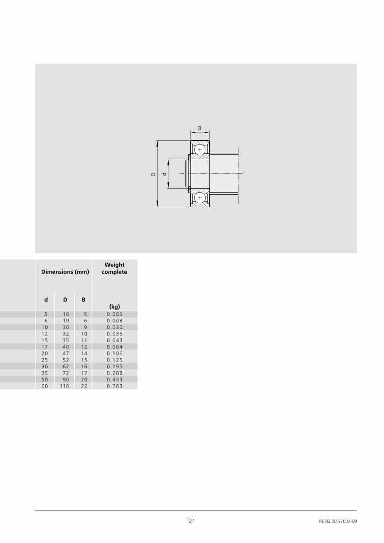
91 RE 83 301/2002-09
dD
B
5 16 5 0 .0056 19 6 0.008
10 30 9 0.03012 32 10 0.03515 35 11 0.04317 40 12 0.06420 47 14 0.10625 52 15 0.12530 62 16 0.19535 72 17 0.28850 90 20 0.45360 110 22 0.783
WeightDimensions (mm) complete
d D B(kg)
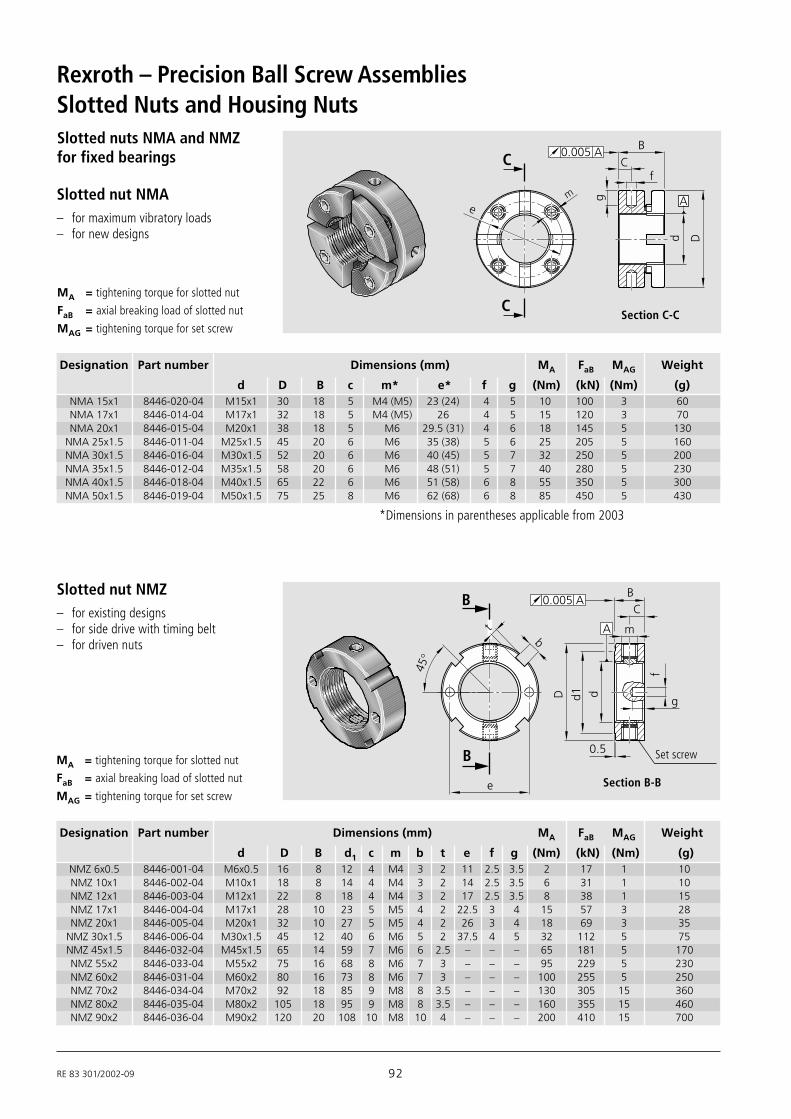
RE 83 301/2002-09 92
Rexroth – Precision Ball Screw Assemblies
Slotted nuts NMA and NMZfor fixed bearings
A
C
C
B
fC
em g
d D
0.005 A
Slotted nut NMZ– for existing designs– for side drive with timing belt– for driven nuts
B
45°
dd1D
0.5
g
f
m
CB
A
0.005 A
B
e
tb
Slotted nut NMA– for maximum vibratory loads– for new designs
Section C-C
Section B-B
Set screw
Slotted Nuts and Housing Nuts
Designation Part number Dimensions (mm) MA FaB MAG Weight
d D B c m* e* f g (Nm) (kN) (Nm) (g)NMA 15x1 8446-020-04 M15x1 30 18 5 M4 (M5) 23 (24) 4 5 10 100 3 60NMA 17x1 8446-014-04 M17x1 32 18 5 M4 (M5) 26 4 5 15 120 3 70NMA 20x1 8446-015-04 M20x1 38 18 5 M6 29.5 (31) 4 6 18 145 5 130
NMA 25x1.5 8446-011-04 M25x1.5 45 20 6 M6 35 (38) 5 6 25 205 5 160NMA 30x1.5 8446-016-04 M30x1.5 52 20 6 M6 40 (45) 5 7 32 250 5 200NMA 35x1.5 8446-012-04 M35x1.5 58 20 6 M6 48 (51) 5 7 40 280 5 230NMA 40x1.5 8446-018-04 M40x1.5 65 22 6 M6 51 (58) 6 8 55 350 5 300NMA 50x1.5 8446-019-04 M50x1.5 75 25 8 M6 62 (68) 6 8 85 450 5 430
Designation Part number Dimensions (mm) MA FaB MAG Weight
d D B d1 c m b t e f g (Nm) (kN) (Nm) (g)
MA = tightening torque for slotted nut
FaB = axial breaking load of slotted nut
MAG = tightening torque for set screw
*Dimensions in parentheses applicable from 2003
MA = tightening torque for slotted nut
FaB = axial breaking load of slotted nut
MAG = tightening torque for set screw
NMZ 6x0.5 8446-001-04 M6x0.5 16 8 12 4 M4 3 2 11 2.5 3.5 2 17 1 10NMZ 10x1 8446-002-04 M10x1 18 8 14 4 M4 3 2 14 2.5 3.5 6 31 1 10NMZ 12x1 8446-003-04 M12x1 22 8 18 4 M4 3 2 17 2.5 3.5 8 38 1 15NMZ 17x1 8446-004-04 M17x1 28 10 23 5 M5 4 2 22.5 3 4 15 57 3 28NMZ 20x1 8446-005-04 M20x1 32 10 27 5 M5 4 2 26 3 4 18 69 3 35
NMZ 30x1.5 8446-006-04 M30x1.5 45 12 40 6 M6 5 2 37.5 4 5 32 112 5 75NMZ 45x1.5 8446-032-04 M45x1.5 65 14 59 7 M6 6 2.5 – – – 65 181 5 170NMZ 55x2 8446-033-04 M55x2 75 16 68 8 M6 7 3 – – – 95 229 5 230NMZ 60x2 8446-031-04 M60x2 80 16 73 8 M6 7 3 – – – 100 255 5 250NMZ 70x2 8446-034-04 M70x2 92 18 85 9 M8 8 3.5 – – – 130 305 15 360NMZ 80x2 8446-035-04 M80x2 105 18 95 9 M8 8 3.5 – – – 160 355 15 460NMZ 90x2 8446-036-04 M90x2 120 20 108 10 M8 10 4 – – – 200 410 15 700
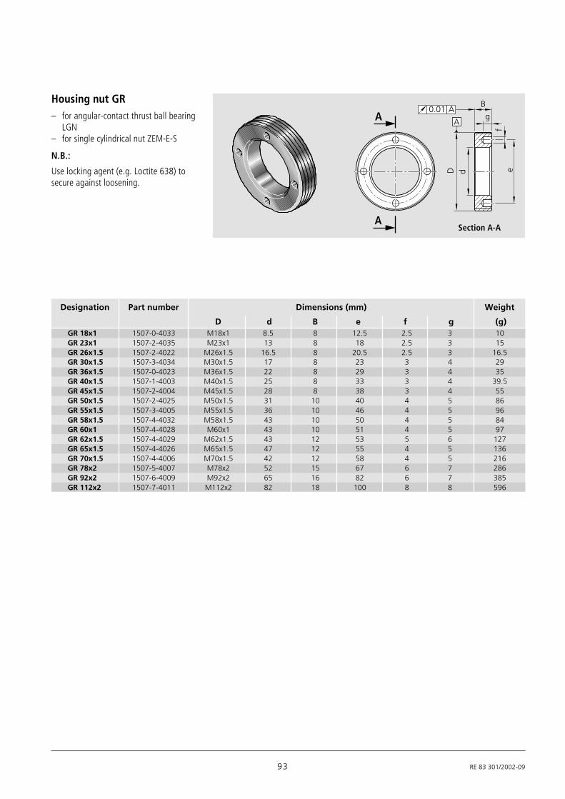
93 RE 83 301/2002-09
Housing nut GR– for angular-contact thrust ball bearing
LGN– for single cylindrical nut ZEM-E-S
A
ef
g
B
A A
0.01 A
D d
Designation Part number Dimensions (mm) Weight
D d B e f g (g)GR 18x1 1507-0-4033 M18x1 8.5 8 12.5 2.5 3 10GR 23x1 1507-2-4035 M23x1 13 8 18 2.5 3 15GR 26x1.5 1507-2-4022 M26x1.5 16.5 8 20.5 2.5 3 16.5GR 30x1.5 1507-3-4034 M30x1.5 17 8 23 3 4 29GR 36x1.5 1507-0-4023 M36x1.5 22 8 29 3 4 35GR 40x1.5 1507-1-4003 M40x1.5 25 8 33 3 4 39.5GR 45x1.5 1507-2-4004 M45x1.5 28 8 38 3 4 55GR 50x1.5 1507-2-4025 M50x1.5 31 10 40 4 5 86GR 55x1.5 1507-3-4005 M55x1.5 36 10 46 4 5 96GR 58x1.5 1507-4-4032 M58x1.5 43 10 50 4 5 84GR 60x1 1507-4-4028 M60x1 43 10 51 4 5 97GR 62x1.5 1507-4-4029 M62x1.5 43 12 53 5 6 127GR 65x1.5 1507-4-4026 M65x1.5 47 12 55 4 5 136GR 70x1.5 1507-4-4006 M70x1.5 42 12 58 4 5 216GR 78x2 1507-5-4007 M78x2 52 15 67 6 7 286GR 92x2 1507-6-4009 M92x2 65 16 82 6 7 385GR 112x2 1507-7-4011 M112x2 82 18 100 8 8 596
N.B.:
Use locking agent (e.g. Loctite 638) tosecure against loosening.
Section A-A

RE 83 301/2002-09 94
Rexroth – Precision Ball Screw Assemblies
Selection criteria for ballscrewsThe following factors should be consideredwhen selecting the ball screw for a givenapplication:
– degree of accuracy required (leaddeviation)
– in-service load conditions– service life– critical speed– buckling load– rigidity/permissible clearance or desired
preload– characteristic speed (max. permissible
linear speed)
The following points should be taken intoconsideration when selecting a ball screwassembly that is to be both cost-efficientand optimally designed:
– The lead is a decisive factor for theload-carrying capacity (depending onthe maximum possible ball diameter)and the drive moment.
– The calculation of the service life shouldbe based on average loads and averagespeeds, not on maximum values.
– In order for us to provide you with acustomized solution, installationdrawings or sketches of the nutenvironment should be enclosed withyour inquiry.
Technical NotesDIN 69 051 Part 1 defines aball screw as follows:An assembly comprising a ball screw shaftand a ball nut and which is capable ofconverting rotary motion into linear motionand vice versa.
Advantages over the Acmescrew drive– The mechanical efficiency of an Acme
screw drive is a maximum 50%,whereas a ball screw can reach amechanical efficiency of up to 98%
– Higher life expectancy due to negligiblewear during operation
– Less drive power required– No stick-slip effect– More precise positioning– Higher travel speed– Less heat-up
Due to their high mechanical efficiency,ball screws are in principle not self-locking.
Safety informationWe recommend that a safety nut beinstalled for particularly criticalapplications in vertical set-ups. Please ask.
100
90
80
70
60
50
40
30
20
10
1 2 3 9 8765400
µ = 0.005
µ = 0.01
µ = 0. 2
µ = 0.3
Lead angle (°)
Effic
ienc
y (%
)
Acme screw
Precision Ball ScrewAssembly
N.B.:
Radial and eccentric forces relative to thescrew must be avoided as they have anegative effect on the life and properfunction of the ball screw.
Where special conditions of operation areinvolved, please ask.
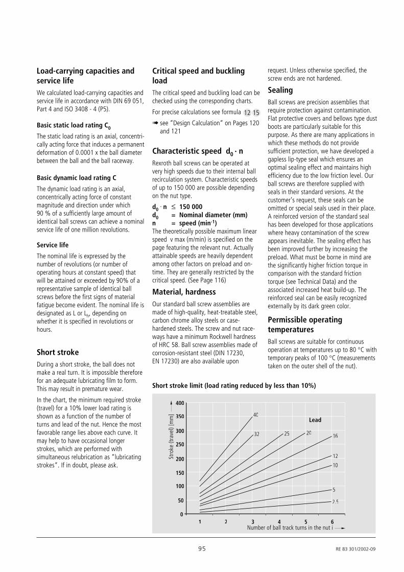
95 RE 83 301/2002-09
Load-carrying capacities andservice lifeWe calculated load-carrying capacities andservice life in accordance with DIN 69 051,Part 4 and ISO 3408 - 4 (P5).
Critical speed and bucklingloadThe critical speed and buckling load can bechecked using the corresponding charts.
For precise calculations see formula
! see “Design Calculation“ on Pages 120and 121
Characteristic speed d0 · nRexroth ball screws can be operated atvery high speeds due to their internal ballrecirculation system. Characteristic speedsof up to 150 000 are possible dependingon the nut type.
d0 . n ≤ 150 000d0 = Nominal diameter (mm)n = speed (min-1)The theoretically possible maximum linearspeed v max (m/min) is specified on thepage featuring the relevant nut. Actuallyattainable speeds are heavily dependentamong other factors on preload and on-time. They are generally restricted by thecritical speed. (See Page 116)
Material, hardnessOur standard ball screw assemblies aremade of high-quality, heat-treatable steel,carbon chrome alloy steels or case-hardened steels. The screw and nut race-ways have a minimum Rockwell hardnessof HRC 58. Ball screw assemblies made ofcorrosion-resistant steel (DIN 17230,EN 17230) are also available upon
12 15
400
350
300
250
200
150
100
50
01 2 3 4 5 6
32 25 20 16
12
10
5
2.52 5
4040
Short stroke limit (load rating reduced by less than 10%)
Stro
ke (t
rave
l) [m
m]
Number of ball track turns in the nut i
Lead
Basic static load rating C0
The static load rating is an axial, concentri-cally acting force that induces a permanentdeformation of 0.0001 x the ball diameterbetween the ball and the ball raceway.
Basic dynamic load rating C
The dynamic load rating is an axial,concentrically acting force of constantmagnitude and direction under which90 % of a sufficiently large amount ofidentical ball screws can achieve a nominalservice life of one million revolutions.
Service life
The nominal life is expressed by thenumber of revolutions (or number ofoperating hours at constant speed) thatwill be attained or exceeded by 90% of arepresentative sample of identical ballscrews before the first signs of materialfatigue become evident. The nominal life isdesignated as L or Lh, depending onwhether it is specified in revolutions orhours.
Short strokeDuring a short stroke, the ball does notmake a real turn. It is impossible thereforefor an adequate lubricating film to form.This may result in premature wear.
In the chart, the minimum required stroke(travel) for a 10% lower load rating isshown as a function of the number ofturns and lead of the nut. Hence the mostfavorable range lies above each curve. Itmay help to have occasional longerstrokes, which are performed withsimultaneous relubrication as “lubricatingstrokes“. If in doubt, please ask.
request. Unless otherwise specified, thescrew ends are not hardened.
SealingBall screws are precision assemblies thatrequire protection against contamination.Flat protective covers and bellows type dustboots are particularly suitable for thispurpose. As there are many applications inwhich these methods do not providesufficient protection, we have developed agapless lip-type seal which ensures anoptimal sealing effect and maintains highefficiency due to the low friction level. Ourball screws are therefore supplied withseals in their standard versions. At thecustomer’s request, these seals can beomitted or special seals used in their place.A reinforced version of the standard sealhas been developed for those applicationswhere heavy contamination of the screwappears inevitable. The sealing effect hasbeen improved further by increasing thepreload. What must be borne in mind arethe significantly higher friction torque incomparison with the standard frictiontorque (see Technical Data) and theassociated increased heat build-up. Thereinforced seal can be easily recognizedexternally by its dark green color.
Permissible operatingtemperaturesBall screws are suitable for continuousoperation at temperatures up to 80 °C withtemporary peaks of 100 °C (measurementstaken on the outer shell of the nut).

RE 83 301/2002-09 96
Rexroth – Precision Ball Screw AssembliesAcceptance Conditions and Tolerance Grades
(Sta
ndar
d: c
= 0
)
Ball screw with ground-thread screw SN-F (SN-R)PPermissible travel deviationin accordance with DIN 69 051, Part 3and ISO 3408-3
Many values are significantly moreaccurate than those defined in DIN 69051,Part 3 and ISO 3408-3
Stan
dard
: c =
0
For ground-thread screws SN-F and SN-R the following values apply in all cases:
ν2πp (µm)Tolerance grade
1 3 5 7 9
4 6 8 10 10
ν300p (µm)Tolerance grade
1 3 5 7 9
6 12 23 52 130
lu ep (µm) νup (µm)
Tolerance grade Tolerance grade
> ≤ 1 3 5 7 9 1 3 50 100 - 8 18 44 110 - 8 18
100 200 - 10 20 48 130 - 10 20200 315 6 12 23 52 150 6 12 23315 400 7 13 25 57 170 6 12 25400 500 8 15 27 63 200 7 13 26500 630 9 16 30 70 220 7 14 29630 800 10 18 35 80 260 8 16 31800 1000 11 21 40 9 17 351000 1250 13 24 46 10 19 391250 1600 15 29 54 11 22 441600 2000 18 35 65 13 25 512000 2500 22 41 77 15 29 592500 3150 26 50 93 17 34 693150 4000 32 62 115 21 41 824000 5000 - 76 140 - 49 995000 6300 - - 170 - - 119
P P
l 1
l u l el e
ep
ep
ν30
0p
300
-0∅l
ν up
up
2≠rad2≠
pν
l 0
c
+
ν
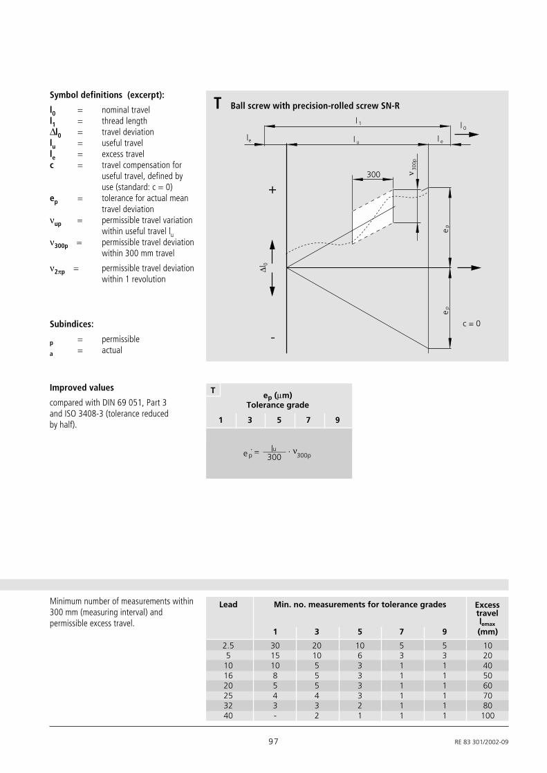
97 RE 83 301/2002-09
Improved values
compared with DIN 69 051, Part 3and ISO 3408-3 (tolerance reducedby half).
ep (µm)Tolerance grade
1 3 5 7 9
T
νe p 300lu
300p´
l 1
l ule
ep
ep
ν 300
p
300
+
-
0∆ l
l e
l 0
c = 0
Symbol definitions (excerpt):
l0 = nominal travell1 = thread length∆l0 = travel deviationlu = useful travelle = excess travelc = travel compensation for
useful travel, defined byuse (standard: c = 0)
ep = tolerance for actual meantravel deviation
νup = permissible travel variationwithin useful travel lu
ν300p = permissible travel deviationwithin 300 mm travel
ν2πp = permissible travel deviationwithin 1 revolution
Ball screw with precision-rolled screw SN-RT
Subindices:
p = permissible
a = actual
Minimum number of measurements within300 mm (measuring interval) andpermissible excess travel.
1 3 5 7 9 (mm)
2.5 30 20 10 5 5 105 15 10 6 3 3 20
10 10 5 3 1 1 4016 8 5 3 1 1 5020 5 5 3 1 1 6025 4 4 3 1 1 7032 3 3 2 1 1 8040 - 2 1 1 1 100
Lead Min. no. measurements for tolerance grades Excesstravellemax

RE 83 301/2002-09 98
Rexroth – Precision Ball Screw Assemblies
Bearing Seat
Nominal Ref. t7p´ in µmdiameter length for l7 ≤ l
ford0 l tolerance grade
above up to 1 3 5; 7; 9
= 6 20 80 5 5 620 50 125 5 5 650 125 200 6 6 7
125 200 315 - 8 12
Coaxial deviation t7´ of the journaldiameter of the ball screw shaft inrelation to the bearing diameter forl7 ≤ l.
t7a 7p≤ t
l7al
Table value t7p applies when I7 ≤ referencelength I.
Where l7 > l then
d0
l 7
Ct7p´
C
Bearing seat
d0
2 d0
AA´t6p
A A´
l 6
Nominal Ref. t6p in µmdiameter length for
l6 ≤ ld0 l tolerance grade
above up to 1 3 5; 7; 9
= 6 20 80 10 12 2020 50 125 12 16 2550 125 200 16 20 25
125 200 315 - 25 25
Radial run-out t6 of the bearingdiameter in relation to AA´ for l6 ≤ l.
t6a 6p≤ t
l6al
Table value t6p applies when I6 ≤ referencelength I.
Where l6 > l then
Acceptance Conditions and Tolerance GradesRun-outs and locationdeviationsbased on DIN 69 051, Part 3and ISO 3408-3
t5max in µml1/d0 for l1 ≥ 4l5
tolerance gradeabove up to 1 3 5 7; 9
40 40 50 64 8040 60 60 75 96 12060 80 100 125 160 20080 100 160 200 256 320
t5p in µm for l5d0 l5 for
tolerance gradeabove up to 1 3 5 7; 9
= 6 12 8012 25 16025 50 315 20 25 32 4050 100 630
100 200 1250
5l 5l 5l
2 d0
d 0
2 d0
l 1
5l 5l5pt
5 m
axt
A A
AA´t5p
A A´
Radial run-out t5 of the outerdiameter of the ball screw shaft overthe length l5 used to determine thestraightness in relation to AA´.

99 RE 83 301/2002-09
2 d0
0d
1D
2 d0
AA´t10p
A A´
fixed
Radial run-out t10 of the outerdiameter D1 of the ball nut inrelation to A and A´ (for preloadedand rotating ball nuts only). Fixscrew against rotation.
Outer t10p in µmdiameter for
tolerance gradesD1
above up to 1 3 5; 7; 9
16 32 10 12 1632 63 12 16 2063 125 16 20 25
125 250 20 25 32250 500 - 32 40
Bearing seat
Axial run-out t8´ of the shaft(bearing) face of the ball screw shaftin relation to the bearing diameter.
d0F
d
C
Ct8p´ Nominal t8p´ in µmdiameter for
tolerance gradesd0
above up to 1 3 5; 7; 9
= 6 63 3 4 563 125 4 5 6
125 200 - 6 8
Axial run-out t9 of the ball nutlocation face in relation to A and A´(for preloaded ball nuts only).
2 d0
F 0d
5D
2 d0
AA´t9p
A A´
Flange t9p in µmdiameter for
tolerance gradesD5
above up to 1 3 5; 7; 9
16 32 10 12 1632 63 12 16 2063 125 16 20 25
125 250 20 25 32250 500 - 32 40
Please ask for details of permissibleaxial and radial run-out for drivennuts.
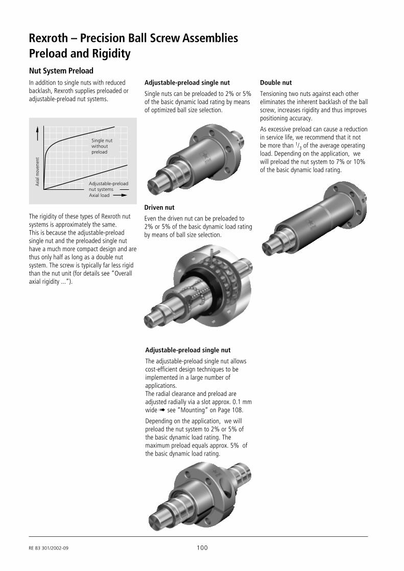
RE 83 301/2002-09 100
Rexroth – Precision Ball Screw AssembliesPreload and Rigidity
The rigidity of these types of Rexroth nutsystems is approximately the same.This is because the adjustable-preloadsingle nut and the preloaded single nuthave a much more compact design and arethus only half as long as a double nutsystem. The screw is typically far less rigidthan the nut unit (for details see “Overallaxial rigidity ...”).
Single nutwithoutpreload
Adjustable-preloadnut systemsAxial load
Axia
l mov
emen
t
In addition to single nuts with reducedbacklash, Rexroth supplies preloaded oradjustable-preload nut systems.
Adjustable-preload single nut
The adjustable-preload single nut allowscost-efficient design techniques to beimplemented in a large number ofapplications.The radial clearance and preload areadjusted radially via a slot approx. 0.1 mmwide ! see “Mounting“ on Page 108.
Depending on the application, we willpreload the nut system to 2% or 5% ofthe basic dynamic load rating. Themaximum preload equals approx. 5% ofthe basic dynamic load rating.
Adjustable-preload single nut
Single nuts can be preloaded to 2% or 5%of the basic dynamic load rating by meansof optimized ball size selection.
Double nut
Tensioning two nuts against each othereliminates the inherent backlash of the ballscrew, increases rigidity and thus improvespositioning accuracy.
As excessive preload can cause a reductionin service life, we recommend that it notbe more than 1/3 of the average operatingload. Depending on the application, wewill preload the nut system to 7% or 10%of the basic dynamic load rating.
Nut System Preload
Driven nut
Even the driven nut can be preloaded to2% or 5% of the basic dynamic load ratingby means of ball size selection.

101 RE 83 301/2002-09
Overall RigidityThe rigidity of a ball screw is alsoinfluenced by all adjoining parts such asbearings, housing bores, nut housings etc.
N.B.:
Please note that in most cases the rigidityRS of the screw will be significantly lowerthan the rigidity Rnu of the nut unit. In anassembly with a diameter of 40 x 10, forexample, the rigidity Rnu of the nut unit is2 to 3 times higher than the rigidity RS ofa screw with a length of 500 mm.
R R R R1111
tot aL s nu16
2. Ball screw shaft is fixed at both ends.
RS1 = Rigidity of the screwdo = Nominal diameterDw = Ball diameterlS1 = Distance between bearing
and nut
R 165 (N/µm)(d -0.71·D )ww 0 0 2
S1S1 17
Dwd 0d 1d 2 The lowest screw rigidity RS2min occurs at
the center of the screw ( lS2 = lS/2)and thus equals:
l S
l S 2S
S2 ≤2
18
19
RS2 = Rigidity of the screwdo = Nominal diameterDw = Ball diameterlS = Distance between bearing
and bearinglS2 = Distance between bearing
and nut
l S 1
1. Ball screw shaft is fixed at one end.
Rigidity of the screw RS
The rigidity of the screw RS depends on thetype of bearing used.
See the corresponding tables for rigidityvalues.
Overall axial rigidity Rtot of the ballscrew
The overall axial rigidity Rtot is comprisedof the component rigidity of the bearingRaL, the screw Rs and the nut Rnu and iscalculated according to the formula:
Rigidity of the bearing RaL
The rigidity of the bearings corresponds tothe values found in the bearingmanufacturer’s catalog.
See the corresponding tables for rigidityvalues.
Rigidity in the area of the nut unitRnu
The rigidity in the area of the nut unit iscalculated according to DIN 69051 (P5).See the corresponding tables for rigidityvalues.
R 165 (N/µm)(d -0.71·D )ww 0 0 2
SS2 S S2S2
(N/µm)S
660RS2min
(d -0.71 D )0 0 wD )wD )2

RE 83 301/2002-09 102
Rexroth – Precision Ball Screw Assemblies
(mm) (mm)6 x 1R x 0.8 - 4 900 1290 0.01 0 56 x 2R x 0.8 - 4 890 1280 0.01 0 58 x 1R x 0.8 - 4 1020 1740 0.01 0 98 x 2R x 1.2 - 4 1870 2760 0.01 0 98 x 2.5R x 1.588 - 3 2200 2800 0.02 0.010 812 x 2R x 1.2 - 4 2240 4160 0.01 0 2112 x 5R x 2 - 3 3800 5800 0.02 0.010 1812 x 10R x 2 - 2 2500 3600 0.02 0.010 1816 x 5R x 3 - 4 12300 16100 0.04 0.020 3216 x 10R x 3 - 3 9600 12300 0.04 0.020 3216 x 16R x 3 - 2 6300 7600 0.04 0.020 3216 x 16R x 3 - 3 9300 12000 0.04 0.020 3220 x 5R x 3 - 4 14300 21500 0.04 0.020 5320 x 5R x 3 - 5 17500 27300 0.04 0.020 5320 x 20R x 3.5 - 2 9100 12100 0.04 0.020 5220 x 20R x 3.5 - 3 13300 18800 0.04 0.020 5220 x 40R x 3.5 - 1x4 8000 14900 0.04 0.020 5225 x 5R x 3 - 4 15900 27200 0.04 0.020 8625 x 10R x 3 - 4 15700 27000 0.04 0.020 8625 x 25R x 3.5 - 2 10100 15100 0.04 0.020 8425 x 25R x 3.5 - 3 14700 23300 0.04 0.020 8425 x 25R x 3.5 -1.2x4 19700 39400 0.04 0.020 8432 x 5R x 3.5 - 4 21600 40000 0.04 0.020 14432 x 5L x 3.5 - 4 21600 40000 0.04 0.020 14432 x 10R x 3.969 - 5 31700 58300 0.04 0.020 14132 x 20R x 3.969 - 2 13500 21800 0.04 0.020 14132 x 20R x 3.969 - 3 19700 33700 0.04 0.020 14132 x 32R x 3.969 - 2 13400 22000 0.04 0.020 14132 x 32R x 3.969 - 3 19500 34000 0.04 0.020 14132 x 32R x 3.969 -1.2-4 26300 57600 0.04 0.020 14140 x 5R x 3.5 - 5 29100 64100 0.04 0.020 23240 x 5L x 3.5 - 5 29100 64100 0.04 0.020 23240 x 10R x 6 - 4 50000 86400 0.07 0.035 21140 x 10L x 6 - 4 50000 86400 0.07 0.035 21140 x 12R x 6 - 4 49900 86200 0.07 0.035 21140 x 16R x 6 - 4 49700 85900 0.07 0.035 21140 x 20R x 6 - 3 37900 62800 0.07 0.035 21140 x 40R x 6 - 2 25500 40300 0.07 0.035 21140 x 40R x 6 - 3 37000 62300 0.07 0.035 21150 x 5R x 3.5 - 5 32000 81300 0.04 0.020 37350 x 10R x 6 - 6 79700 166500 0.07 0.035 34550 x 12R x 6 - 6 79600 166400 0.07 0.035 34550 x 16R x 6 - 6 79400 166000 0.07 0.035 34550 x 20R x 6.5 - 3 47900 87900 0.07 0.035 34050 x 20R x 6.5 - 5 75700 149700 0.07 0.035 34050 x 40R x 6.5 - 2 32100 55800 0.07 0.035 34050 x 40R x 6.5 - 3 46500 85900 0.07 0.035 34063 x 10R x 6 - 6 88800 214300 0.07 0.035 56963 x 20R x 6.5 - 3 53200 112100 0.07 0.035 56363 x 20R x 6.5 - 5 83900 190300 0.07 0.035 56363 x 40R x 6.5 - 2 36900 74300 0.07 0.035 56363 x 40R x 6.5 - 3 53400 114100 0.07 0.035 56380 x 10R x 6.5 - 6 108400 291700 0.07 0.035 93880 x 20R x 9 - 6 170900 403900 0.09 0.045 89480 x 20R x 12.7 - 6 262700 534200 0.11 0.055 832100 x 10R x 6.5 - 6 119500 371900 0.07 0.035 1501100 x 20R x 12.7 - 6 295100 686400 0.11 0.055 1366125 x 10R x 6.5 - 6 130600 468700 0.07 0.035 2391125 x 20R x 12.7 - 6 326500 870400 0.11 0.055 2220
Preload andOverall RigiditySingle nuts
Dynamic drag torque, preloadand rigidity for screws withsingle nuts from diameter 16 mm(smaller dias. without backlashonly)FSZ-E-S, FEP-E-S (2% C only),FEM-E-S, FEM-E-C, ZEM-E-S;SEM-E-S and SEM-E-C(observe centering diameter D1to be set)
(ZEV-E-S with backlash only!)
T0 = overall dynamic drag torqueT0 = Tpr0 + TRDC = basic dynamic load ratingC0 = basic static load ratingTRD = dynamic drag torque of
2 sealsRS = rigidity of the screwRnu = rigidity of the nutTpr0 = dynamic drag torque
without a seal
do = nominal diameterP = leadDw = ball diameteri = number of ball track turns
The dynamic drag torque indicates inpractice the nut preloading.
Size
do x P x Dw - iLoad ratings
dyn.
C
(N)
stat.
C0
(N)
RS
N·m
Backlash of
single nut
Stan
dar
d
Red
uce
d
N.B.:
Measurement of the dynamic load torque! see “Mounting“ on Page 108.
Overall rigidity
of the screw
µm( )

103 RE 83 301/2002-09
max. max. min. max. min. max. min. max. min. max. min. max.
70 0.004 15.953 15.987
100 0.009 23.940 23.97560 0.006 23.940 23.975
210 0.040 280 0.06 0.14 0.05 0.15 0.04 0.16 27.940 27.975 27.940 27.975160 0.030 220 0.05 0.11 0.04 0.12 0.03 0.12 27.940 27.975 27.940 27.975100 0.020 140 0.03 0.07 0.03 0.08 0.02 0.08 27.950 27.978 32.945 32.973160 0.030 210 0.04 0.10 0.04 0.11 0.03 0.12 27.950 27.978 32.945 32.973260 0.060 350 0.09 0.20 0.07 0.21 0.06 0.23 35.935 35.970 32.935 32.970330 0.070 440 0.11 0.25 0.09 0.26 0.07 0.28130 0.040 180 0.05 0.13 0.05 0.14 0.04 0.15 35.945 35.973 37.945 37.973200 0.050 270 0.08 0.19 0.07 0.20 0.05 0.21 35.945 35.973 37.945 37.973170 0.030 - - - - - - - - - - -310 0.080 410 0.12 0.28 0.10 0.30 0.08 0.32 39.935 39.970 37.935 37.970320 0.080 430 0.12 0.27 0.10 0.29 0.08 0.31 39.935 39.970 37.935 37.970160 0.050 210 0.08 0.18 0.06 0.19 0.05 0.20 39.945 39.973 47.945 47.973240 0.070 320 0.11 0.26 0.09 0.28 0.07 0.29 39.945 39.973 47.945 47.973350 0.080 - - - - - - - - - - -380 0.140 500 0.26 0.43 0.24 0.45 0.21 0.48 49.935 49.970 47.935 47.970380 0.140 500 0.26 0.43 0.24 0.45 0.21 0.48 49.935 49.970 47.935 47.970500 0.200 670 0.38 0.63 0.36 0.66 0.30 0.71 49.935 49.970 47.935 47.970200 0.090 270 0.16 0.27 0.15 0.28 0.13 0.30 49.945 49.973 55.941 55.969300 0.130 410 0.24 0.39 0.22 0.41 0.19 0.44 49.945 49.973 55.941 55.969200 0.090 260 0.16 0.27 0.15 0.28 0.13 0.30 49.945 49.973 55.941 55.969300 0.120 400 0.23 0.39 0.22 0.41 0.19 0.44 49.945 49.973 55.941 55.969440 0.110 - - - - - - - - - - -550 0.230 720 0.44 0.73 0.41 0.76 0.35 0.81 62.931 62.966 55.931 55.966550 0.230 720 0.44 0.73 0.41 0.76 0.35 0.81 62.931 62.966 55.931 55.966500 0.400 670 0.80 1.20 0.75 1.25 0.70 1.30 62.931 62.966 62.931 62.966500 0.400 670 0.80 1.20 0.75 1.25 0.70 1.30 62.931 62.966 62.931 62.966510 0.400 680 0.80 1.20 0.75 1.25 0.70 1.30 62.931 62.966510 0.400 680 0.80 1.19 0.75 1.24 0.70 1.29380 0.300 510 0.61 0.91 0.57 0.95 0.53 0.99 62.941 62.969 62.941 62.969240 0.200 330 0.38 0.64 0.36 0.66 0.31 0.71 62.941 62.969 71.941 71.969370 0.300 490 0.59 0.89 0.56 0.93 0.52 0.96 62.941 62.969 71.941 71.969640 0.320 830 0.64 0.96 0.60 1.00 0.56 1.04 74.931 74.966 67.931 67.966890 0.800 1180 1.59 2.39 1.49 2.49 1.39 2.59 74.931 74.966 71.931 71.966900 0.800 1190 1.59 2.39 1.49 2.49 1.39 2.59 74.931 74.966910 0.790 1210 1.59 2.38 1.49 2.48 1.39 2.58470 0.480 630 0.96 1.44 0.90 1.50 0.84 1.56 74.941 74.969 84.936 84.964780 0.760 1050 1.51 2.27 1.42 2.37 1.32 2.46 74.941 74.969 84.936 84.964300 0.320 410 0.64 0.96 0.60 1.00 0.56 1.04 74.941 74.969 84.936 84.964450 0.470 610 0.93 1.40 0.87 1.45 0.81 1.51 74.941 74.969 84.936 84.9641050 1.120 1380 2.38 3.22 2.24 3.36 2.10 3.50 89.926 89.961 84.926 84.961560 0.670 750 1.34 2.01 1.26 2.09 1.17 2.18 94.936 94.964 94.936 94.964930 1.060 1250 2.25 3.04 2.11 3.17 1.98 3.30 94.936 94.964 94.936 94.964380 0.460 510 0.93 1.39 0.87 1.45 0.81 1.51 94.936 94.964 94.936 94.964570 0.670 770 1.35 2.02 1.26 2.10 1.18 2.19 94.936 94.964 94.936 94.9641240 1.730 1610 3.69 4.99 3.47 5.20 3.25 5.42 104.926 104.961 104.926 104.9611410 2.730 1880 5.81 7.86 5.47 8.20 5.13 8.55 124.931 124.959 124.931 124.9591400 4.200 1870 8.93 12.08 8.41 12.61 7.88 13.14 124.931 124.959 124.931 124.9591430 2.390 1830 5.08 6.87 4.78 7.17 4.48 7.471680 5.900 2230 12.54 16.97 11.8 17.71 11.07 18.441600 3.270 2020 6.94 9.39 6.53 9.80 6.12 10.201970 8.160 2600 17.35 23.47 16.33 24.49 15.30 25.51
1 ; 3 ; 5 ; 7
2% C preload
Tpr0 (Nm)
Tolerance grade1 3 ; 5
Tpr0 (Nm)
Tolerance grade
Rnu
(N/µm)
5% C preload
7
Rnu
(N/µm)
centering diameter D1 afteradjustment (mm)
Screws with adjustable-
preload single nuts
SEM-E-C SEM-E-S
Screws with single nuts
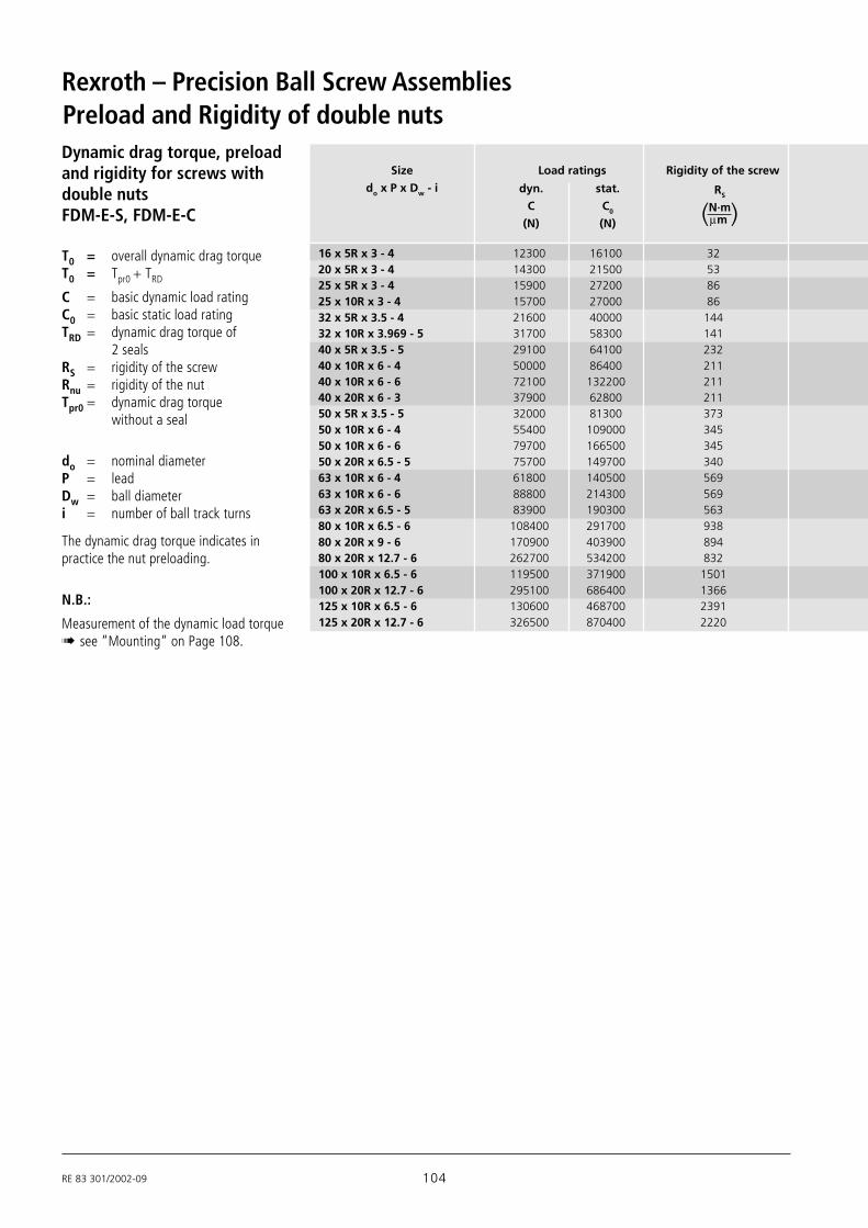
RE 83 301/2002-09 104
Rexroth – Precision Ball Screw AssembliesPreload and Rigidity of double nutsDynamic drag torque, preloadand rigidity for screws withdouble nutsFDM-E-S, FDM-E-C
T0 = overall dynamic drag torqueT0 = Tpr0 + TRD
C = basic dynamic load ratingC0 = basic static load ratingTRD = dynamic drag torque of
2 sealsRS = rigidity of the screwRnu = rigidity of the nutTpr0 = dynamic drag torque
without a seal
do = nominal diameterP = leadDw = ball diameteri = number of ball track turns
The dynamic drag torque indicates inpractice the nut preloading.
N.B.:
Measurement of the dynamic load torque! see “Mounting“ on Page 108.
16 x 5R x 3 - 4 12300 16100 3220 x 5R x 3 - 4 14300 21500 5325 x 5R x 3 - 4 15900 27200 8625 x 10R x 3 - 4 15700 27000 8632 x 5R x 3.5 - 4 21600 40000 14432 x 10R x 3.969 - 5 31700 58300 14140 x 5R x 3.5 - 5 29100 64100 23240 x 10R x 6 - 4 50000 86400 21140 x 10R x 6 - 6 72100 132200 21140 x 20R x 6 - 3 37900 62800 21150 x 5R x 3.5 - 5 32000 81300 37350 x 10R x 6 - 4 55400 109000 34550 x 10R x 6 - 6 79700 166500 34550 x 20R x 6.5 - 5 75700 149700 34063 x 10R x 6 - 4 61800 140500 56963 x 10R x 6 - 6 88800 214300 56963 x 20R x 6.5 - 5 83900 190300 56380 x 10R x 6.5 - 6 108400 291700 93880 x 20R x 9 - 6 170900 403900 89480 x 20R x 12.7 - 6 262700 534200 832100 x 10R x 6.5 - 6 119500 371900 1501100 x 20R x 12.7 - 6 295100 686400 1366125 x 10R x 6.5 - 6 130600 468700 2391125 x 20R x 12.7 - 6 326500 870400 2220
Size
do x P x Dw - i
Load ratings
dyn.
C
(N)
stat.
C0
(N)
RS
N·m
Rigidity of the screw
µm( )
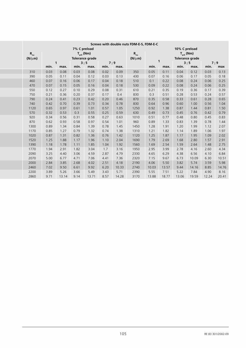
105 RE 83 301/2002-09
7% C preload 10% C preloadTpr0 (Nm)
Tolerance grade1 3 ; 5 7 ; 91 3 ; 5 7 ; 9
min. max. min. max. min. max. min. max. min. max. min. max
310 0.03 0.08 0.03 0.08 0.02 0.09 350 0.05 0.11 0.04 0.12 0.03 0.13390 0.05 0.11 0.04 0.12 0.03 0.13 430 0.07 0.16 0.06 0.17 0.05 0.18460 0.07 0.16 0.06 0.17 0.04 0.18 510 0.1 0.22 0.08 0.24 0.06 0.25470 0.07 0.15 0.05 0.16 0.04 0.18 530 0.09 0.22 0.08 0.24 0.06 0.25550 0.12 0.27 0.10 0.29 0.08 0.31 610 0.21 0.35 0.19 0.36 0.17 0.39750 0.21 0.36 0.20 0.37 0.17 0.4 830 0.3 0.51 0.28 0.53 0.24 0.57790 0.24 0.41 0.23 0.42 0.20 0.46 870 0.35 0.58 0.33 0.61 0.28 0.65740 0.42 0.70 0.39 0.73 0.34 0.78 830 0.64 0.96 0.60 1.00 0.56 1.04
1120 0.65 0.97 0.61 1.01 0.57 1.05 1250 0.92 1.38 0.87 1.44 0.81 1.50570 0.32 0.53 0.3 0.55 0.25 0.59 630 0.49 0.73 0.45 0.76 0.42 0.79920 0.34 0.56 0.31 0.58 0.27 0.63 1010 0.51 0.77 0.48 0.80 0.45 0.83870 0.62 0.93 0.58 0.97 0.54 1.01 960 0.89 1.33 0.83 1.39 0.78 1.44
1300 0.89 1.34 0.84 1.39 0.78 1.45 1450 1.28 1.91 1.20 1.99 1.12 2.071170 0.85 1.27 0.79 1.32 0.74 1.38 1310 1.21 1.82 1.14 1.89 1.06 1.971020 0.87 1.31 0.82 1.36 0.76 1.42 1120 1.25 1.87 1.17 1.95 1.09 2.021520 1.25 1.88 1.17 1.96 1.10 2.04 1690 1.79 2.69 1.68 2.80 1.57 2.911390 1.18 1.78 1.11 1.85 1.04 1.92 1560 1.69 2.54 1.59 2.64 1.48 2.751770 1.94 2.91 1.82 3.04 1.7 3.16 1950 2.95 3.99 2.78 4.16 2.60 4.342090 3.25 4.40 3.06 4.59 2.87 4.79 2330 4.65 6.29 4.38 6.56 4.10 6.842070 5.00 6.77 4.71 7.06 4.41 7.36 2320 7.15 9.67 6.73 10.09 6.30 10.512000 2.84 3.85 2.68 4.02 2.51 4.18 2190 4.06 5.50 3.82 5.74 3.59 5.982460 7.02 9.50 6.61 9.92 6.20 10.33 2740 10.03 13.57 9.44 14.16 8.85 14.762200 3.89 5.26 3.66 5.49 3.43 5.71 2390 5.55 7.51 5.22 7.84 4.90 8.162860 9.71 13.14 9.14 13.71 8.57 14.28 3170 13.88 18.77 13.06 19.59 12.24 20.41
Rnu
(N/µm)
Tpr0 (Nm)
Tolerance grade
Rnu
(N/µm)
Screws with double nuts FDM-E-S, FDM-E-C

RE 83 301/2002-09 106
Rexroth – Precision Ball Screw AssembliesFriction Torques of SealsSeal torque for single anddouble nuts
(ZEV-E-S is supplied withouta seal)T0 = overall dynamic drag torqueT0 = Tpr0 + TRDTRD = dynamic drag torque of
2 sealsTpr0 = dynamic drag torque
without seal
do = nominal diameterP = leadDw = ball diameteri = number of ball track turns
Size
do x P x Dw - i
TRD
approx.
(Nm)
Standard
seal
N.B.:
Measurement of the dynamic load torque! see “Mounting“ on Page 108.
TRD
approx. (Nm)
Reinforced seal;
for precision-rolled screw
SN-R only
6 x 1R x 0.8 - 4 0.010 -6 x 2R x 0.8 - 4 0.010 -8 x 1R x 0.8 - 4 0.010 -8 x 2R x 1.2 - 4 0.020 -8 x 2.5R x 1.588 - 3 0.015 -12 x 2R x 1.2 - 4 0.030 -12 x 5R x 2 - 3 0.030 -12 x 10R x 2 - 2 0.030 -16 x 5R x 3 - 4 0.080 -16 x 10R x 3 - 3 0.080 -16 x 16R x 3 - 2 0.080 -16 x 16R x 3 - 3 0.080 -20 x 5R x 3 - 4 0.100 -20 x 5R x 3 - 5 0.100 -20 x 20R x 3.5 - 2 0.120 -20 x 20R x 3.5 - 3 0.120 -25 x 5R x 3 - 4 0.120 0.3425 x 10R x 3 - 4 0.150 0.2925 x 25R x 3.5 - 2 0.200 -25 x 25R x 3.5 - 3 0.200 -32 x 5R x 3.5 - 4 0.250 0.5132 x 5L x 3.5 - 4 0.250 -32 x 10R x 3.969 - 5 0.250 0.4632 x 20R x 3.969 - 2 0.250 0.4932 x 20R x 3.969 - 3 0.250 0.4932 x 32R x 3.969 - 2 0.250 0.4532 x 32R x 3.969 - 3 0.250 -40 x 5R x 3.5 - 5 0.400 0.8540 x 5L x 3.5 - 5 0.400 -40 x 10R x 6 - 4 0.400 0.9140 x 10L x 6 - 4 0.400 -40 x 16R x 6 - 4 0.400 -40 x 20R x 6 - 3 0.400 0.5440 x 40R x 6 - 2 0.400 -40 x 40R x 6 - 3 0.400 -50 x 5R x 3.5 - 5 0.500 -50 x 10R x 6 - 6 0.600 0.9550 x 12R x 6 - 6 0.600 -50 x 16R x 6 - 6 0.600 -50 x 20R x 6.5 - 3 0.600 -50 x 20R x 6.5 - 5 0.600 -50 x 40R x 6.5 - 2 0.600 -50 x 40R x 6.5 - 3 0.700 -63 x 20R x 6.5 - 3 1.200 1.063 x 20R x 6.5 - 5 1.200 1.063 x 40R x 6.5 - 2 1.200 1.463 x 40R x 6.5 - 3 1.200 1.480 x 10R x 6.5 - 6 1.400 -80 x 20R x 9 - 6 2.200 -80 x 20R x 12.7 - 6 2.200 -100 x 10R x 6.5 - 6 2.200 -100 x 20R x 12.7 - 6 2.800 -125 x 10R x 6.5 - 6 3.600 -125 x 20R x 12.7 - 6 5.000 -
Dynamic drag torque of2 seals

107 RE 83 301/2002-09
Inserting the sealPosition the nut on the screw as illustratedin the diagram. Insert the seal so that itsprojection is in the recess and press it inuntil it snaps into the groove. Whileturning the nut on the screw, watch thesealing lip carefully and straighten it ifnecessary by applying pressure to the endsurface. Ensure that the lip is notdamaged.
Please bear in mind thefollowing when modifying andretrofitting the seals:All ground-thread screws SN-F and theprecision-rolled screws SN-R with smallleads are designed as single (Fig. 1). Thereis therefore only one ball track on thescrew.
However precision-rolled screws SN-R withhigher leads are designed as double orquadruple (Figs. 2 and 3). The sealinggeometry here is therefore different fromthat for the ground-thread screwsSN-F. The distinction is made clear by thepart number on the component.
“Reinforced seals” for precision-rolled screws SN-R are available asan option. These are identified by theiropal-green color and their part number.
Fig. 1Single seal
Fig. 2Seal for double precision-rolled screw SN-R withaverage lead
Fig. 3Seal for quadruple precision-rolled screw SN-R with highlead
5 - 10 mm
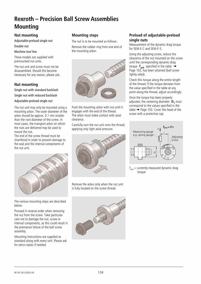
RE 83 301/2002-09 108
Rexroth – Precision Ball Screw AssembliesMounting
The nut is to be mounted as follows:
Remove the rubber ring from one end ofthe mounting arbor.
Push the mounting arbor with nut until itengages with the end of the thread.The arbor must make contact with axialclearance.
Carefully turn the nut unit onto the thread,applying only light axial pressure.
Remove the arbor only when the nut unitis fully located on the screw thread.
The various mounting steps are describedbelow.
Proceed in reverse order when removingthe nut from the screw. Take particularcare not to damage the nut, screw orinternal components, as this could result inthe premature failure of the ball screwassembly.
Mounting instructions are supplied asstandard along with every unit. Please askfor extra copies if needed.
Preload of adjustable-preloadsingle nutsMeasurement of the dynamic drag torquefor SEM-E-C and SEM-E-S.
Using the adjusting screw, reduce theclearance of the nut mounted on the screwuntil the corresponding dynamic dragtorque Tpr0 specified in the table !Page 102, has been attained (ball screwlightly oiled).
Check this torque along the entire lengthof the thread; if the torque deviates fromthe value specified in the table at anypoint along the thread, adjust accordingly.
Once the torque has been properlyadjusted, the centering diameter D1 mustcorrespond to the values specified in thetable ! Page 103. Cover the head of thescrew with a protective cap.
Tpra = currently measured dynamic drag torque
T = F·r
r
pra
D1
FMeasuring gaugee.g. spring gauge
Adjustingscrew
Mounting steps
The nut unit may only be mounted using amounting arbor. The outer diameter of thearbor should be approx. 0.1 mm smallerthan the root diameter of the screw. Inmost cases, the transport arbor on whichthe nuts are delivered may be used tomount the nut.The end of the screw thread must bechamfered in order to prevent damage tothe seal and the internal components ofthe nut unit.
Adjustable-preload single nut
Double nut
Machine tool line
These models are supplied withpremounted nut units.
The nut unit and screw must not bedisassembled. Should this becomenecessary for any reason, please ask.
Nut mounting
Nut mountingSingle nut with standard backlash
Single nut with reduced backlash
Adjustable-preload single nut

109 RE 83 301/2002-09
StorageBall screw assemblies are high-qualitysystems that must be treated with duecare. In order to prevent damage andcontamination, the elements should not beremoved from the protective wrappinguntil immediately before installation.Once they have been removed from thepackaging, they must be set down on V-shaped cradles.
Installation in the MachineIt is not normally necessary to remove thepreservative coating before installation.
– If the ball screw is contaminated it mustfirst be cleaned (see “Cleaning”) andreoiled
– Push the nut unit into the mountingbore, taking care to avoid any impactsor misalignment.
– Tighten the mounting screws using atorque wrench if necessary. Maximumtightening torque for the steel/steelmaterial pairing(Rm ≥ 370 N/mm2), see table.
Screw diameter(mm)
Tightening torque (Nm)strength class
to DIN ISO 898:
8.8 10.9 12.9
M 3 1.3 1.8 2.1
M 4 2.7 3.8 4.6
M 6 9.5 13 16
M 8 23 32 39
M 10 46 64 77
M 12 80 110 135
M 16 195 275 330
Condition as deliveredRexroth Ball Screws are normally deliveredwith an initial supply of grease type KlüberMicrolube GB 0 NLGI 0. Relubrication withgrease or oil is thus possible in principle,but you will need to check that thelubricant used is compatible with the initialsupply. The ball screws can also besupplied with only a preservative coating ifpreferred.
Important:
The selected lubricant must be in the nutbefore the machine is started.
CleaningVarious cleaning agents can be used todegrease and wash the assembly:
– aqueous cleaning agents– organic cleaning agents
Important:
Immediately after cleaning, thoroughly dryall parts, then apply a preservative coatingor anti-corrosion oil.In all cases, take care to observe theappropriate legal regulations (environmen-tal protection, health and safety at work,etc.) as well as the specifications for thecleaning agent (e.g. handling).
– For the steel/aluminium and aluminium/aluminium material pairings(Rm ≥ 280 N/mm2), the maximumtightening torques specified in thefollow table apply.When screwing into aluminium, thelength of thread engagement should beat least 1.5 times the screw diameter.
Screw diameter(mm)
Tightening torque (Nm)strength class
to DIN ISO 898:
8.8 10.9 12.9
M 3 1.2 1.2 1.2
M 4 2.4 2.4 2.4
M 6 8.5 8.5 8.5
M 8 20 20 20
M 10 41 41 41
M 12 70 70 70
M 16 175 175 175
Steel/steel material pairing
Steel/aluminium and aluminium/aluminium material pairing

RE 83 301/2002-09 110
Rexroth – Precision Ball Screw Assemblies
Grease lubricationThe advantage of grease lubrication isthat the ball screw can run long distanceson one supply of grease. As a result, alubricating system is not required in manycases. The amount of grease used shouldfill the nuts to approximately half of theircapacity.
All commercially available ball bearinglubricating greases may be used.Read the lubricant manufacturer’sspecifications carefully! Never use greaseswith solid lubricant components (e.g.graphite or MoS2).
Oil lubricationThe influence of the temperature on theperformance of the ball screw is verysignificant, as the thermal expansion ofthe ball screw interferes with thepositioning accuracy of the assembly.
One of the advantages of oil lubricationover grease lubrication is therefore theminimized heat build-up of the ball screw,particularly at high speeds.
As a rule, commercially available mineralbase oils used for ball bearings aresuitable. The necessary viscosity dependson the speed, temperature and loadconditions of the respective application(see DIN 51501, 51517, 51519 and GfTWorksheet 3).
Oils ranging from ISO VG 68 to approx.ISO VG 460 are used in practice. The highviscosity grades (e.g. ISO VG 460) shouldbe preferred in general and particularly forslow running screws. A maximum relubri-cation interval of up to 10 operating hourscan be attained with small quantities fromthe adjacent table.
Please ask for details for driven nuts.
Lubrication
do Initial Relubrication Revolu- Travel (km)lubrication oil oil tions with lead P =
Ve(ml) Vn (ml)/10h U (mill.) 5 10 16 20 25 32 40
8 0.300 0.030 1.3 7 13 21 26 33 42 52
12 0.300 0.030 1.3 7 13 21 26 33 42 52
16 0.300 0.030 1.3 7 13 21 26 33 42 52
20 0.600 0.060 1.0 5 10 16 20 25 32 40
25 0.600 0.060 1.0 5 10 16 20 25 32 40
32 0.600 0.060 1.0 5 10 16 20 25 32 40
40 2.000 0.400 1.0 5 10 16 20 25 32 40
50 4.000 0.800 1.0 5 10 16 20 25 32 40
63 4.000 0.800 1.0 5 10 16 20 25 32 40
d0 Revolu- Travel (km)
tions with lead P =
U (mill.) 5 10 16 20 25 32 40
≤ 40 50 250 500 800 1000 1250 1600 2000
> 40 10 50 100 160 200 250 320 400
Relubrication quantity, seetable for NLGI 2 greases.
d0 = nominal diameter
Standard lubrication practices for ballbearings also apply to ball screws.Lubricant loss is, however, greater thanthat e.g. from conventional ball bearingsdue to the axial motion between the screwand the nut.
Relubrication quantity and intervals for oil
Relubrication intervals for NLGI 2 greases
Limit conditions:Load = ≤ 0.2 Cnmin = 100 min-1
Tempmax. nut = 80 °CTempcontinuous nut = 60 °C
Greases in accordance with DIN 51825K2K and, for higher loads, KP2K of NLGIClass 2 in accordance with DIN 51818 arerecommended for the longest possiblelubrication intervals. Tests have shownthat greases of NLGI Class 00 achieve onlyabout 50% of the running performance ofClass 2 at higher loads.The lubrication interval depends on manyfactors such as the degree of contami-nation, operating temperature, load, etc.The following values can thus serve only asa guideline.
d0 = nominal diameter
Set-up: - anyOperatingmode: - driven screw
- no short stroking orhypercritical operation
Sealing: - standard
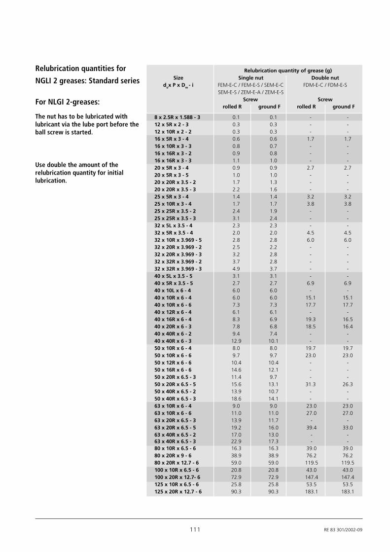
111 RE 83 301/2002-09
For NLGI 2-greases:
8 x 2.5R x 1.588 - 3 0.1 0.1 - -12 x 5R x 2 - 3 0.3 0.3 - -12 x 10R x 2 - 2 0.3 0.3 - -16 x 5R x 3 - 4 0.6 0.6 1.7 1.716 x 10R x 3 - 3 0.8 0.7 - -16 x 16R x 3 - 2 0.9 0.8 - -16 x 16R x 3 - 3 1.1 1.0 - -20 x 5R x 3 - 4 0.9 0.9 2.7 2.720 x 5R x 3 - 5 1.0 1.0 - -20 x 20R x 3.5 - 2 1.7 1.3 - -20 x 20R x 3.5 - 3 2.2 1.6 - -25 x 5R x 3 - 4 1.4 1.4 3.2 3.225 x 10R x 3 - 4 1.7 1.7 3.8 3.825 x 25R x 3.5 - 2 2.4 1.9 - -25 x 25R x 3.5 - 3 3.1 2.4 - -32 x 5L x 3.5 - 4 2.3 2.3 - -32 x 5R x 3.5 - 4 2.0 2.0 4.5 4.532 x 10R x 3.969 - 5 2.8 2.8 6.0 6.032 x 20R x 3.969 - 2 2.5 2.2 - -32 x 20R x 3.969 - 3 3.2 2.8 - -32 x 32R x 3.969 - 2 3.7 2.8 - -32 x 32R x 3.969 - 3 4.9 3.7 - -40 x 5L x 3.5 - 5 3.1 3.1 - -40 x 5R x 3.5 - 5 2.7 2.7 6.9 6.940 x 10L x 6 - 4 6.0 6.0 - -40 x 10R x 6 - 4 6.0 6.0 15.1 15.140 x 10R x 6 - 6 7.3 7.3 17.7 17.740 x 12R x 6 - 4 6.1 6.1 - -40 x 16R x 6 - 4 8.3 6.9 19.3 16.540 x 20R x 6 - 3 7.8 6.8 18.5 16.440 x 40R x 6 - 2 9.4 7.4 - -40 x 40R x 6 - 3 12.9 10.1 - -50 x 10R x 6 - 4 8.0 8.0 19.7 19.750 x 10R x 6 - 6 9.7 9.7 23.0 23.050 x 12R x 6 - 6 10.4 10.4 - -50 x 16R x 6 - 6 14.6 12.1 - -50 x 20R x 6.5 - 3 11.4 9.7 - -50 x 20R x 6.5 - 5 15.6 13.1 31.3 26.350 x 40R x 6.5 - 2 13.9 10.7 - -50 x 40R x 6.5 - 3 18.6 14.1 - -63 x 10R x 6 - 4 9.0 9.0 23.0 23.063 x 10R x 6 - 6 11.0 11.0 27.0 27.063 x 20R x 6.5 - 3 13.9 11.7 - -63 x 20R x 6.5 - 5 19.2 16.0 39.4 33.063 x 40R x 6.5 - 2 17.0 13.0 - -63 x 40R x 6.5 - 3 22.9 17.3 - -80 x 10R x 6.5 - 6 16.3 16.3 39.0 39.080 x 20R x 9 - 6 38.9 38.9 76.2 76.280 x 20R x 12.7 - 6 59.0 59.0 119.5 119.5100 x 10R x 6.5 - 6 20.8 20.8 43.0 43.0100 x 20R x 12.7- 6 72.9 72.9 147.4 147.4125 x 10R x 6.5 - 6 25.8 25.8 53.5 53.5125 x 20R x 12.7 - 6 90.3 90.3 183.1 183.1
Relubrication quantity of grease (g)Size Single nut Double nut
dox P x Dw - i FEM-E-C / FEM-E-S / SEM-E-C FDM-E-C / FDM-E-SSEM-E-S / ZEM-E-A / ZEM-E-S
Screw Screwrolled R ground F rolled R ground F
Relubrication quantities for
NGLI 2 greases: Standard series
The nut has to be lubricated withlubricant via the lube port before theball screw is started.
Use double the amount of therelubrication quantity for initiallubrication.

RE 83 301/2002-09 112
Rexroth – Precision Ball Screw Assemblies
For NLGI 2 greases:
6 x 1R x 0.8- 4 0.06 - - -6 x 2R x 0.8- 4 0.12 - - -8 x 1R x 0.8 - 4 0.12 - - -8 x 2R x 1.2 - 4 0.24 - - -8 x 2.5R x 1.588 - 3 0.10 - - -12 x 2R x 1.2 - 4 0.15 - - -12 x 5R x 2 - 3 0.30 - - 0.312 x 10R x 2 - 2 0.30 - - 0.316 x 5L x 3 - 3 - - - 0.8516 x 5R x 3 - 3 - - - 0.8516 x 10R x 3 - 3 - - - 1.020 x 5R x 3 - 4 - 0.7 - 1.220 x 5R x 3 - 5 - - - -20 x 40R x 3.5 - 1 x 4 - - 1.6 -25 x 5R x 3 - 4 - 1.1 - -25 x 10R x 3 - 4 - 1.3 - -25 x 25R x 3.5 - 1.2 x 4 - - 1.5 -32 x 5R x 3.5 - 4 - 1.6 - -32 x 10R x 3.969 - 5 - 2.3 - -32 x 20R x 3.969 - 2 - 2.0 - -32 x 32R x 3.969 - 1.2 x 4 - - 2.6 -40 x 5R x 3.5 - 5 - 2.2 - -40 x 10R x 6 - 4 - 5.2 - -40 x 20R x 6 - 3 - 6.7 - -
Relubrication quantities for NGLI 2 greases: Miniature, ECO series
The nut has to be lubricated withlubricant via the lube port before theball screw is started.
Relubrication quantity of grease (g)Size Single nut, precision-rolled screw R
d0x P x Dw-iFEM-E-B Miniature FSZ-E-S FEP-E-S ZEV-E-S

113 RE 83 301/2002-09
Relubrication quantities for driven nut FAR-B-S
Radial or axial lubricating port (M6)
The driven nut can be supplied withgrease via the outer race of the angular-contact thrust ball bearing. The only pointto bear in mind here is that the nut has tobe stationary during the lubricationprocedure. The nut can be located at anyposition on the screw.
This provides a very simple solution to theproblem of a rotating lubricating port onthe nut itself.
Two lubricating ports (M6) with radial oraxial access are provided. When theassembly is delivered, both ports aresealed by setscrews. The desired lubri-cating port is opened by removing thesetscrew.
Relubrication quantity of grease (g)Size Driven nut
d0 x P x Dw-i FAR-B-SScrew
rolled R ground F
32 x 10R x 3.969 - 5 3.2 3.232 x 20R x 3.969 - 3 3.7 3.232 x 32R x 3.969 - 3 5.6 4.340 x 10R x 6 - 5 7.7 7.740 x 20R x 6 - 3 9.0 7.840 x 40R x 6 - 3 14.8 11.650 x 10R x 6 - 6 11.2 11.250 x 20R x 6.5 - 5 17.9 15.150 x 40R x 6.5 - 3 21.4 16.263 x 10R x 6 - 6 12.7 12.763 x 20R x 6.5 - 5 22.1 18.463 x 40R x 6.5 - 3 26.4 19.9
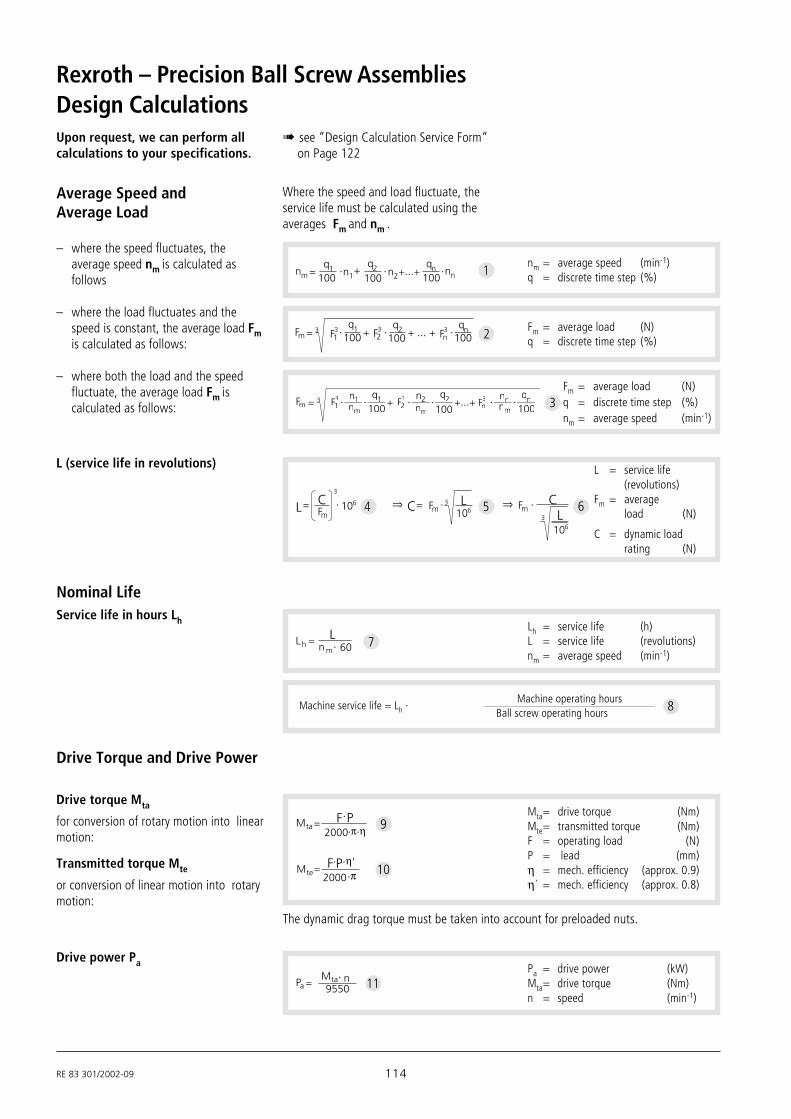
RE 83 301/2002-09 114
Rexroth – Precision Ball Screw AssembliesDesign CalculationsUpon request, we can perform allcalculations to your specifications.
! see “Design Calculation Service Form“on Page 122
L = service life(revolutions)
Fm = averageload (N)
C = dynamic loadrating (N)
⇒ ⇒3
L CFm
C Fm3 L106
106 FmC
3 L106
4 5 6
L (service life in revolutions)
– where both the load and the speedfluctuate, the average load Fm iscalculated as follows:
Fm = average load (N)q = discrete time step (%)nm = average speed (min-1)
3
Fm 3 F13
100 100 100F23 Fn
3q1 q2 qn
– where the load fluctuates and thespeed is constant, the average load Fmis calculated as follows:
2 Fm = average load (N)q = discrete time step (%)
– where the speed fluctuates, theaverage speed nm is calculated asfollows
nm = average speed (min-1)q = discrete time step (%)n +m
q1 q2n1 n2qn nn100 100 100
1
Average Speed andAverage Load
Where the speed and load fluctuate, theservice life must be calculated using theaverages Fm and nm .
Drive power Pa Pa = drive power (kW)Mta= drive torque (Nm)n = speed (min-1)
PanMta
9550 11
The dynamic drag torque must be taken into account for preloaded nuts.
Transmitted torque Mte
or conversion of linear motion into rotarymotion:
Drive torque Mta
for conversion of rotary motion into linearmotion:
Drive Torque and Drive Power
Mta= drive torque (Nm)Mte= transmitted torque (Nm)F = operating load (N)P = lead (mm)η = mech. efficiency (approx. 0.9)η´ = mech. efficiency (approx. 0.8)
π ηMta
F P2000
ηπMte
F P2000
10
9
Nominal LifeService life in hours Lh Lh = service life (h)
L = service life (revolutions)nm = average speed (min-1)
L60n m
Lh 7
8Machine operating hours
Ball screw operating hoursMachine service life = Lh ·
Fmm 3 F113
100 100 100F22
3 Fnn3 qnn1
nm
q1 n2 q2 nnnnmnm

115 RE 83 301/2002-09
Calculation Example
Service life
Operating conditions
The service life of the machine should be40,000 operating hours with the ballscrew operating 60% of the time.
Proposed ball screw: 63 x 10
F1 = 50 000 N at n1 = 10 min-1 for q1 = 6 % of the duty cycleF2 = 25 000 N at n2 = 30 min-1 for q2 = 22 % of the duty cycleF3 = 8 000 N at n3 = 100 min-1 for q3 = 47 % of the duty cycleF4 = 2 000 N at n4 = 1 000 min-1 for q4 = 25 % of the duty cycle
100 %
Calculation procedure
+6100 100 100 100100 100022 47 253010nm
nm 304 min-1
Average speed nm1
Average load Fm for variable load andvariable speed.
3
Basic dynamic load rating C
≈C 66492 N38757C 437 760 000106 5
Machine service lifeLhMachine operating hours
Ball screw operating hours
40000 60100
24000 h
60L Lh nm
Lh
L 437 760 000 revolutionsL 24000 304 60
Required service life L (revolutions)
The life L can be calculated by transposingthe formulas and :7 8
Cross check
Service life of the selected ball screw inrevolutions L ≈ 1042 · 106 revolutionsL 88 800 106
3
87574
Service life in hours Lh The life of the selected ball screw assemblyis thus greater than the required servicelife of 24,000 hours (including operatinghours).A smaller ball screw could therefore beselected.
7
Result and selection
The ball screw can now be selected fromthe Dimension Tables:
e.g. ball screw,size 63 x 10 R x 6-6, with preloaded singlenut with flange FEM-E-S,dyn. load rating C = 88 800 N,part number 1512-6-4013.
L 1042 106
57 167 hours≈
h
Lh
304 60
2510Fm 500003 30
30
6304 100 250003 30
304 10022
80003 100304 100
4720003 1000
304 100
Fm 8757 N
N.B.:
Take into account the dynamic loadrating of the screw bearing used.

RE 83 301/2002-09 116
Rexroth – Precision Ball Screw Assemblies
0.2 0.3 0.4 0.5 0.6 0.8 1 2 3 4 5 6 7 8 9 10
20
30
40
50
60
70
80
90100
200
300
400
500
600
800
1000
2000
3000
70
80
90
100
200
300
400
500
600
800
1000
2000
3000
100
200
300
400
500
600
800
1000
2000
3000
200
300
400
500
600
800
1000
2000
3000
8063
5040
328
1216
2025
100125
End fixity I II III IV
fnk value 27.4 18.9 12.1 4.3
Length ln (m)
l n l 1
Crit
ical
spe
ed n
k (m
in-1
)
fixed
fixed
fixed
float
ing
float
ing
float
ing
fixed
fre
e
l n2 (min )
d2nk fnk710 -112
nkzul = 0.8 · nk (min-1)13
nk = critical speed (min-1)nkzul = permissible operating speed (min-1)fnk = corrector value determined by bearingd2 = root diameter (mm),
see Dimension Tablesln = critical length (mm) for preloaded nut systemsl1 = threaded length (mm)
Where ln = l1 for non-preloaded nut systems
For screw ends form 31 (P. 62) the end fixity can be assumed to be “fixed”.
ExampleAccording to the graph, the critical speedis 1850 min-1.The permissible operating speed is thus1850 min-1 x 0.8 = 1480 min-1.
The maximum operating speed in ourcalculation example of n4 = 1000 min-1 istherefore below the permissible operatingspeed.
Screw diameter = 63 mmLength ln = 2.4 mEnd fixity II (fixed - supported)
Critical Speed nkThe critical speed nk depends on thediameter of the screw, the type of endfixity and the free length ln. No allowancemust be made for guidance by a nutwithout preload.
The operating speed should not reachmore than 80% of the critical speed.The characteristic speed and the max.permissible linear speed must be takeninto account, see "Technical Notes" P.95
Design Calculations

117 RE 83 301/2002-09
Permissible axial load on screwFk (buckling load)
Example
axia
l loa
d on
scr
ew F
k (kN
)
Length lk (m)
f Fk value End fixity
2.6 IV
10.2 III
20.4 II
40.6 Il k
F K
0.5
0.6
0.70.80.91.0
2
3
4
5
7
89
10
6
20
30
40
50
60
708090
100
200
300
400
500
600
800
1000
2000
3000
0.1 0.2 0.3 0.4 0.5 0.6 0.8 1 2 3 4 5 6 7 8 9 10
0.2 0.3 0.4 0.5 0.6 0.8 2 3 4 5 6 7 8 9 10
0.2 0.3 0.4 0.5 0.6 0.8 2 3 4 5 6 7 8 9 10
8x2,5
1
1
2 3 4 5 6 7 8 9 100.4 0.5 0.6 10.2 0.30.1
16x16
12x5
16x5 - 16x10
50x5
50x1050x20 - 50x40
40x5
40x4040x10 - 40x20
32x5 - 32x10
32x20 - 32x32
25x25
25x5 - 25x10
20x5
20x20
125x10
100x10
125x20
100x20
80x10
80x20
63x10
63x20 - 63x40
0.8
lk2 (N)Fk fFk
410d2
4
(N)FkzulFk215
14
Fk = theoretically permissible axialload on screw
Fkzul = permissible axial load duringoperation
fFk = corrector value determinedby bearing
d2 = root diameter (mm)see Dimension Tables
lk = unsupported threadedlength (mm)
The permissible axial load on the screw Fkdepends on the diameter of the screw, thetype of end fixity and the effective free
(unsupported) length lk. A safety factor ofg ≥ 2 should be taken into considerationwhen determining the permissible axialload.
Screw diameter = 63 mm,lead = 10 mm,Length lk = 2.4 mEnd fixity II (fixed - supported)
According to the graph, the theoreticallypermissible axial load is 360 kN. Apermissible axial load on the screw of360 kN : 2 = 180 kN is achieved whenapplying the safety factor 2. Thistherefore lies above the maximumoperating load of F1 = 50 kN used in ourcalculation example.

RE 83 301/2002-09 118
Rexroth – Precision Ball Screw Assemblies
MountingSlotted nut NMA, NMZ
The bearings are preloaded by tightening thenuts.In order to prevent settling phenomena, werecommend first tightening the slotted nut bytwice the value of the tightening torque MAand then easing the load. Only then shouldthe slotted nut be retightened to thespecified tightening torque MA.The two setscrews are then alternatelytightened using a hexagon socket wrench.The components are disassembled in thereverse order, i.e. the setscrews are to beremoved before the slotted nut.The slotted nuts can be used several timeswhen properly assembled and disassembledby competent personnel.The inner raceways of the bearings aredimensioned in such a way as to achieve adefined bearing preload sufficient for mostapplications when the slotted nut istightened (MA in accordance with DimensionTable).
End Bearings, Design Notes, Mounting InstructionsBearing DesignFor customer-machined screw ends, pleaseobserve the design notes given for screwends and housings.
For Rexroth screw end designs !see “End Machining Details“ starting onPage 54.
Rexroth delivers complete drive systems,including the end bearings. Calculationsare performed with the formulas used inthe antifriction bearing industry.
Accuracy
Screw end
IT4 A
A
IT3
0.8
0.8
d IT
6
C
IT4
1.6
C
IT5
1.6
D J6
Housing
P5 toDIN 620
P5 toDIN 620
2 . 5
2
Series Bore Axial Radial Tolerance (µm)d runout clearance
Bore Outer Width(mm) (µm) diameter
≤ 50 > 50
+ 3≤ 10 preloaded - 10 - 250- 5
> 10 preloaded - 10 - 11 - 13 - 250
≤ 25preloaded -5 -10 -500
> 25
LGF-C...LGN-C...
LGF-B...LGN-B...
Outer raceway markings for paired bearings
Angular-contact thrust ball bearingsand deep-groove ball bearings
When mounting the angular-contact thrustball bearings LGF and LGN, ensure that themounting forces are exerted only on thebearing rings. Never apply mounting forcesvia the antifriction bearing elements or theseal rings! The two sections of the innerraceway may not be separated duringassembly or disassembly for any reason!Tighten the mounting screws for screw-downor flange-mounted bearings in cross-wisesequence. The mounting screws may besubjected only to tension amounting to amaximum of 70% of their yielding point. Thescrew-down (LGF) bearings have a groove onthe cylindrical surface of the outer racewayfor disassembly. The individual bearings ofthe bearing pair series LGF-C... and LGN-C...are marked on the cylindrical surfaces of theouter raceways (see diagram). The markingsreveal the bearing sequence. The sealingrings should face outward after proper.

119 RE 83 301/2002-09
Mounting the Housing SEBTighten the pillow block mounting screwsin crosswise sequence. See table for max.tightening torque.The housing nut fixes the entire bearingunit in the housing.Use screws and pins to fix the housing nutin place.
N.B.:
Take care to align the screw and nutassembly, the bearings and the guidewayprecisely with one another.
O2O1 O 3 O 4
h
Mounting screw Locating pins
Size h O1 O2 O3
DIN 912 DIN 912 Tapered pin(hardened)
O4Straight pin
d0 x P (mm) (DIN 6325)
8 x 2.5 8 M5 x 20 M6 x 16 4 x 2012 x 5 8 M5 x 20 M6 x 16 4 x 2016 x 5 11 M8 x 35 M10 x 25 8 x 4016 x 10 11 M8 x 35 M10 x 25 8 x 4016 x 16 11 M8 x 35 M10 x 25 8 x 4020 x 5 11 M8 x 35 M10 x 25 8 x 4020 x 20 11 M8 x 35 M10 x 25 8 x 4025 x 5 14 M10 x 40 M12 x 30 10 x 5025 x 10 14 M10 x 40 M12 x 30 10 x 5025 x 25 14 M10 x 40 M12 x 30 10 x 5032 x 5 14 M10 x 40 M12 x 30 10 x 5032 x 10 14 M10 x 40 M12 x 30 10 x 5032 x 20 14 M10 x 40 M12 x 30 10 x 5032 x 32 14 M10 x 40 M12 x 30 10 x 5040 x 5 16 M12 x 50 M14 x 35 10 x 5040 x 10 16 M12 x 50 M14 x 35 10 x 5040 x 20 16 M12 x 50 M14 x 35 10 x 5040 x 40 16 M12 x 50 M14 x 35 10 x 50
Strength class of O1; O2 M5 M6 M8 M10 M12 M14
8.8 5.5 9.5 23 46 80 125
12.9 9.5 16 39 77 135 215
Lubrication, Mounting the Housing
Lubrication of the endbearingsBearings for ball screw assemblies arelubricated with grease for a lifetime ofreliable service.It should be noted, however, that greaselubrication does not facilitate thedissipation of heat in the bearings.The bearing temperature should thereforenot exceed 50 °C, particularly in machinetool applications.Angular-contact thrust ball bearings of theseries LGF, LGN are lubricated for life withgrease KPE2K to DIN 51825.
Nm

RE 83 301/2002-09 120
Rexroth – Precision Ball Screw Assemblies
Resulting and equivalentbearing loadsAngular-contact thrust ball bearings arepreloaded. The chart shows the resultingaxial bearing load Fa as a function ofpreload and axial operating load FaB.If the system is primarily subject to axialoperating loads, then F = Fa.
α = pressure angleX, Y= dimensionless factorFa = resulting bearing loadFaB = operating load
If the radial operating forces are notinsignificant, the equivalent bearing loadsare calculated according to formula .
Bearings for ball screw assemblies are alsoable to accommodate tilting moments. Asa rule, the moments that usually occur dueto the weight and drive motion of thescrew do not need to be incorporated inthe calculation of the equivalent bearingload.
α = 60° X Y
1.9 0.55
0.92 1
Fa 2.17≤rF
>Fa 2.17rF
20
Internal preload limit and resultingbearing load
F = X · Fr + Y · Fa
Fr = radial bearing load (N)Fa = resulting axial bearing load (N)F = equivalent bearing load (N)20
Operating load FaB (N)
Resu
lting
bea
ring
load
Fa
(N)
1) Four row version
End Bearings, Design Calculations
2000 4000 6000
1000
2000
3000
4000
5000
6000
7000
8000
9000
10000
11000
12000
8000 10000 12000
d = 30
d = 20
10d=25
d = 6d = 10
1)
13000
14000
15000
16000
17000
18000
14000 16000 18000
d=50
d=40
d = 35
d = 17d = 12
d=301)
Limits
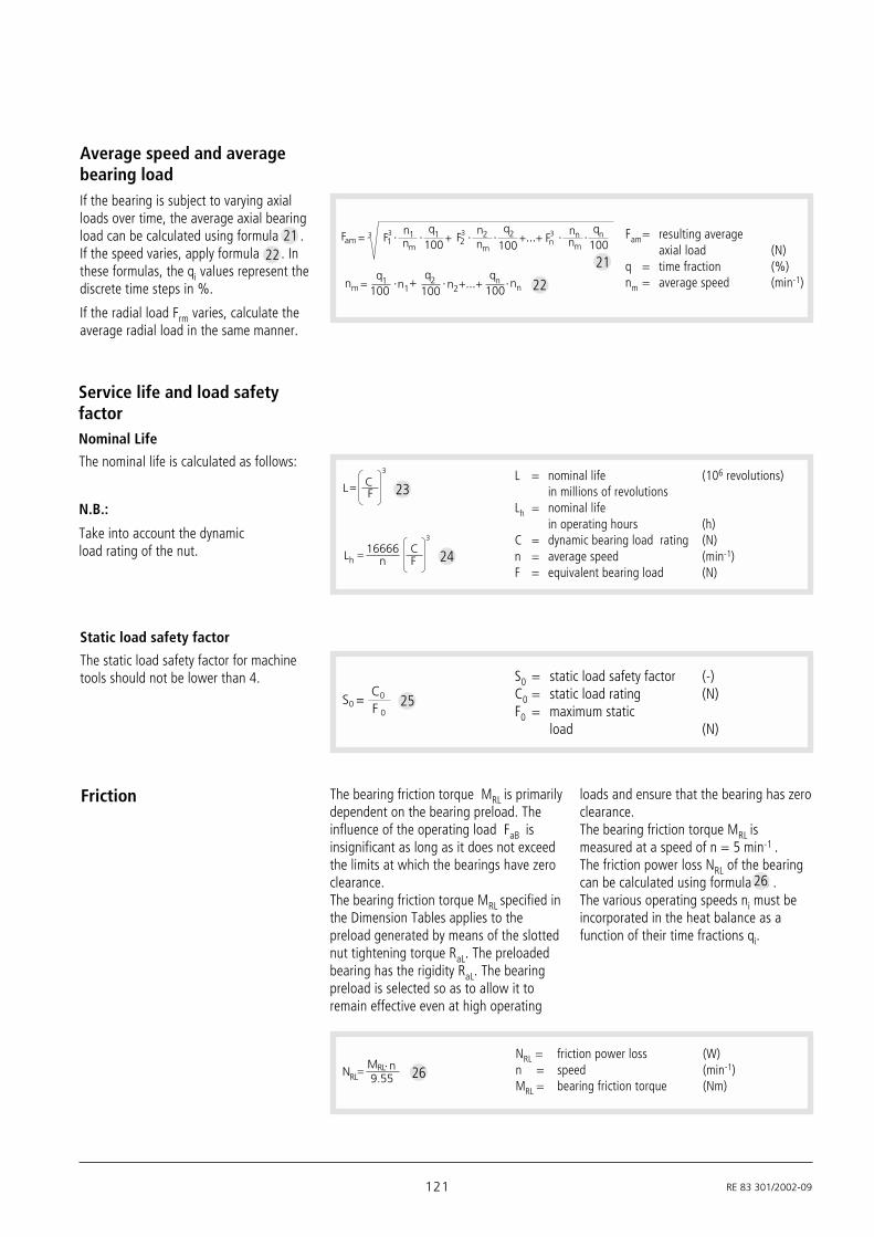
121 RE 83 301/2002-09
Static load safety factor
The static load safety factor for machinetools should not be lower than 4.
Service life and load safetyfactor
The nominal life is calculated as follows:
N.B.:
Take into account the dynamicload rating of the nut.
Nominal Life
Friction The bearing friction torque MRL is primarilydependent on the bearing preload. Theinfluence of the operating load FaB isinsignificant as long as it does not exceedthe limits at which the bearings have zeroclearance.The bearing friction torque MRL specified inthe Dimension Tables applies to thepreload generated by means of the slottednut tightening torque RaL. The preloadedbearing has the rigidity RaL. The bearingpreload is selected so as to allow it toremain effective even at high operating
loads and ensure that the bearing has zeroclearance.The bearing friction torque MRL ismeasured at a speed of n = 5 min-1 .The friction power loss NRL of the bearingcan be calculated using formula 26 .The various operating speeds ni must beincorporated in the heat balance as afunction of their time fractions qi.
26
NRL = friction power loss (W)n = speed (min-1)MRL = bearing friction torque (Nm)
NRLMRL n9.55 26
Average speed and averagebearing loadIf the bearing is subject to varying axialloads over time, the average axial bearingload can be calculated using formula .If the speed varies, apply formula . Inthese formulas, the qi values represent thediscrete time steps in %.
If the radial load Frm varies, calculate theaverage radial load in the same manner.
Fam= resulting averageaxial load (N)
q = time fraction (%)nm = average speed (min-1)
Fam3 F1
3
100 100 100F2
3 Fn3 qnn1
nm
q1 n2 q2 nnnmnm
n +mq1 q2n1 n2
qn nn100 100 100
2122
22
21
3
L16666
Fh nC
3
L CF
L = nominal life (106 revolutions)in millions of revolutions
Lh = nominal lifein operating hours (h)
C = dynamic bearing load rating (N)n = average speed (min-1)F = equivalent bearing load (N)
23
24
S0 = static load safety factor (-)C0 = static load rating (N)F0 = maximum static
load (N)
S0 =C0
F 025

RE 83 301/2002-09 122
Rexroth – Precision Ball Screw Assemblies
Operating conditionsLoads (N) Speeds (1/min) Discrete time steps (%)
F1 = at n1 = to q1 =
F2 = at n2 = to q2 =
F3 = at n3 = to q3 =
F4 = at n4 = to q4 =
F5 = at n5 = to q5 =
F6 = at n6 = to q6 =
Average load (P.114) Average speed (P.114) Sum of time steps
Fm = nm = Q = 100%
Application: New design Revised design
Maximum static load: N
Required service life _____________________ Operating hours or ____________________ x 106 ball screw revolutions
Screw end fixed
fixed fixed floating fixed
I II III IV
fixed floating floating free
Selected:
Installation conditions (enclose drawings/sketches if possible!)
Type of lubrications
Operating temperature: °C - min/max. / °C
Exceptional operating conditions:
Design Calculation Service Form Alternatively, technical design calculation can beperformed by the customer with our WINKGT software
Rexroth Star GmbH97419 SchweinfurtGermany
Telephone +49 (0) 97 21-9 37-0Fax +49 (0) 97 21-9 37-2 88e-mail [email protected]
To: Precision Ball ScrewAssemblies Department
(PP. 120/121)Drawing enclosed
Sender
Company Name
Address Department
Telephone
Fax

123 RE 83 301/2002-09
Sender OEM User Dealer
Company Name
Address Department
Telephone
Fax
N.B.: The processing of Inquiries / Orders based on customer drawings is also possible of course.Inquiry/Order Form
Ball screw assembly
Screw SN X X
Example of an order
SEM-E-S 20 x 5R x 3 - 4
20 x 5R x 3
1 2 T7
T7
R
R
81Z120
81Z120
41Z120
41Z120
1250
1250
1 1
1 0
Ball screw assembly
Screw SN X Xxx
xx -
Quantity Order for ……… units ……… per month, ……… per year, per order or ………………………….
Comments ……………………………………………………………………………………………………………………...
Ball screw assembly
Screw SN X Xxx
xx -
Ball screw assembly
Screw SN X Xxx
xx -
Comments:
Enclosures: Drawing Other
Rexroth Star GmbH97419 SchweinfurtGermany
Telephone +49 (0) 97 21-9 37-0Fax +49 (0) 97 21-9 37-2 88e-mail [email protected]
To: Precision Ball ScrewAssemblies Department

Prin
ted
on c
hlor
ine-
free
ble
ache
d pa
per
Rexroth Star GmbHD-97419 Schweinfurt
A Bosch RexrothGroup Company
Telephone (0 97 21) 9 37-0
Fax 0 97 219 37-9 37-2 75(general)
Fax 0 97 219 37-9 37-2 88(direct)
Internet www.boschrexroth.de
e-mail [email protected]
Printed in Germany - p 2002/12/3/SCH
Rexroth Precision Ball Screw AssembliesEnd Bearings andNut Housings
RE 83 301/2002-09
Great care has been taken during thecompilation of this publication to ensureall the information contained is accurate.We accept no responsibility however forany damage resulting fromincorrect or incomplete informationcontained.
For deliveries and other services in thecourse of commercial business, thegeneral terms and conditions for suppliesand services contained in the valid pricelists and the confirmations of order apply.
As our products are constantly in theprocess of further development, they aresubject to alteration without notice.
Reproduction of this document, even inextract form, is only permitted with ourapproval.