precision ball screw assemblies - loziska.com · 10 bosch rexroth ag precision ball screw...
TRANSCRIPT
The Drive & Control Company
Precision Ball Screw Assemblies R310EN 3301 (2008.07)

Bosch Rexroth AG
www.boschrexroth.com/brl
Linear Motion and Assembly Technologies
Ball Rail SystemsRoller Rail SystemsLinear Bushings and Shafts
Ball Screw DrivesLinear Motion Systems
Basic Mechanical ElementsManual Production SystemsTransfer Systems

3Bosch Rexroth AGPrecision Ball Screw AssembliesR310EN3301 (2008.07)
Precision Ball Screw AssembliesProduct Overview 4
Nuts and Nut Housings 4
Screws, Bearings and Accessories 6
Definition of Precision Ball Screw Assembly 8
Precision Ball Screw Assemblies with Driven Screws 10
Precision Ball Screw Assemblies for All Applications 12
Application Examples 14
Inquiries and Orders 16
Ordering Code 20
Nuts 22
Miniature Single Nut with Flange FEM-E-B 22
Screw-in Nut ZEV-E-S 24
Single Nut with Flange and Recirculation Caps FBZ-E-S 26
Single Nut with Flange and Recirculation Caps FSZ-E-S 28
Single Nut with Flange and Recirculation Caps FEP-E-S 30
Single Nut with Flange FEM-E-C 32
Adjustable-Preload Single Nut SEM-E-C 34
Single Nut with Flange FEM-E-S 36
Adjustable-Preload Single Nut SEM-E-S 38
Cylindrical Single Nut ZEM-E-S 40
2-start Single Nut with Flange FED-E-B 42
Double Nut with Flange FDM-E-C 44
Double Nut with Flange FDM-E-S 46
Nut Housings 48
Nut Housing MGS 48
Nut Housing MGD 50
Nut Housing MGA-Z 52
Screws 54
End Machining Details 56
Bearings 82
Pillow Block Unit SEC-F 82
Pillow Block Unit SEC-L 84
Pillow Block Unit SEB-F 86
Pillow Block Unit SEB-L 88
Bearing LAF 90
Bearing LAN 92
Bearing LAD 94
Bearing LAL 96
Slotted Nuts and Housing Nuts 98
Slotted Nuts NMA, NMZ and NMG for Fixed Bearings 98
Technical Data 100
Technical Notes 100
Acceptance Conditions and Tolerance Grades 102
Preload and Rigidity 106
Friction Torques of Seals 112
Mounting 114
Lubrication 116
Design Calculations 120
End Bearings 126
Design Notes, Mounting Instructions 126
Lubrication, Mounting the Housing 127
Design Calculations 128
Design Calculation Service Form 130

4 Bosch Rexroth AG Precision Ball Screw Assemblies R310EN 3301 (2008.07)
Product Overview
Nuts and Nut HousingsNuts PageMiniature series
Dia
met
er d
0
Lead P1
6 8
12
2 10 5 2.5 Miniature single nut with flangeFEM-E-B
22
ECO series
Dia
met
er d
0
Lead P
1216202532
5 10
Screw-in nutScrew-in nutZEV-E-S
24
Single nut with flange and recirculation capsFBZ-E-S
26D
iam
eter
d0
Lead P
20253240
5 10 20 Single nut with flange FBZ-E-S
Single nut with flange FSZ-E-S
Single nut with flange and recirculation capsFSZ-E-S
28
Speed series
Dia
met
er d
0
Lead P
25202532
32 40Single nut with flange and recirculation capsFEP-E-S
30
Standard series
Dia
met
er d
0
Dia
met
er d
0
Lead P
2.58
12 16 20 25 32 40 50 63 80
5 1 0 1 2 1 6 2 0 2 5 3 2 40
Single nut Double nut
Lead P
405063
20 25 40
2-start single nut with flange FED-E-B
Single nut with flangeDIN 69 051, Part 5FEM-E-C
32
Adjustable-preload single nut DIN 69 051, Part 5SEM-E-C
34
Single nut with flangeFEM-E-S
36
Adjustable-preload single nut SEM-E-S
38
Cylindrical single nutZEM-E-S
40
2-start single nut with flange FED-E-B
42
Double nut with flangeDIN 69 051, Part 5FDM-E-C
44
Double nut with flangeFDM-E-S
46

5Bosch Rexroth AGPrecision Ball Screw AssembliesR310EN 3301 (2008.07)
Nut housings PageMGSfor Standard seriesFEM-E-SFDM-E-SSEM-E-SFEP-E-S
48
D
iam
eter
d0
D
iam
eter
d0
Lead P
2.5
16 20 25 32 40 50 63 80
5 1 0 1 2 1 6 2 0 2 5 3 2 4 0
Lead P
2.5
16 20 25 32 40 50 63 80
5 1 0 1 2 1 6 2 0 2 5 3 2 4 0
MGD
MGS
MGA-Z
MGDfor Standard seriesFEM-E-CFDM-E-CSEM-E-C
50
MGA-Zfor cylindrical single nutZEM-E-S
52

6 Bosch Rexroth AG Precision Ball Screw Assemblies R310EN 3301 (2008.07)
Product Overview
Screws, Bearings and AccessoriesScrews Page
8 x 2.5
16 x 5 , 10 , 16
25 x 5, 1 0, 2 5 32 x 5, 1 0, 20, 3 2 40 x 5 / 50 x 5
50 x 1 0, 1 2, 1 6, 20, 40 63 x 10 , 20, 4 0 80 x 10
1500 2500 7500
80 x 201)
4500 4800
5000
d 0 x P
40 x 10 , 12 , 16 , 20, 4 0
6x1 / 6x2 / 8x1 / 8x2
12 x 2, 5, 1 0
20 x 5, 20, 4 0
Maximum length standard, available at short notice available upon requestNuts 80 x 20R x 12.7 - 6 available up to a thread length of 2500 mm, with preload
1)
Precision-rolled screw SN-RTolerance gradesT5, T7, T9T3 available upon request
54
Acceptance conditions 102
Screw end machining Page56
D
iam
eter
d0
Lead P2.5
8121620253240506380
5 10 12 16 20 25 32 40
6
21
7Bosch Rexroth AGPrecision Ball Screw AssembliesR310EN 3301 (2008.07)
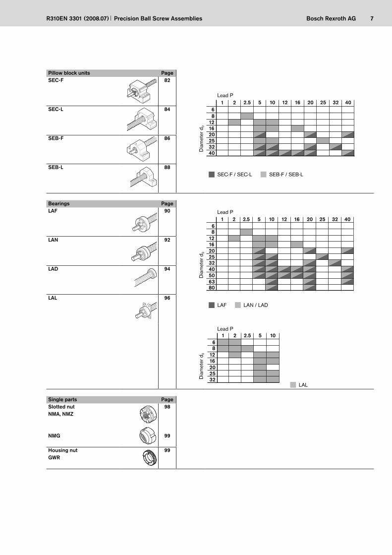
Pillow block units PageSEC-F 82
D
iam
eter
d0
Lead P2.5
8121620253240
5 10 12 16 20 25 32 401 26
SEC-F / SEC-L SEB-F / SEB-L
SEC-L 84
SEB-F 86
SEB-L 88
Bearings PageLAF 90
Dia
met
er d
0
Lead P2.5
8121620253240506380
5 10 12 16 20 25 32 406
1 2
LAF LAN / LAD
LAN 92
LAD 94
LAL 96
Dia
met
er d
0
Lead P2.5
81216202532
5 106
1 2
LAL
Single parts PageSlotted nut NMA, NMZ
NMG
98
99
Housing nut GWR
99
--
8 Bosch Rexroth AG Precision Ball Screw Assemblies R310EN 3301 (2008.07)
Product Overview
Definition of Precision Ball Screw Assembly
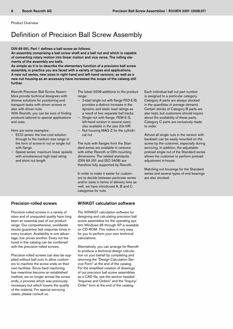
DIN 69 051, Part 1 defines a ball screw as follows:An assembly comprising a ball screw shaft and a ball nut and which is capable of converting rotary motion into linear motion and vice versa. The rolling ele-ments of the assembly are balls.As simple as it is to describe the elementary function of a precision ball screw assembly, in practice you are faced with a variety of types and applications.A new nut series, new sizes in right-hand and left-hand versions, as well as a new nut housing as an accessory have increased the scope of the catalog still further.
Rexroth Precision Ball Screw Assem-blies provide technical designers with diverse solutions for positioning and transport tasks with driven screws or also with driven nuts.With Rexroth, you can be sure of finding products tailored to special applications and uses.
Here are some examples:ECO series: the low-cost solution through to the medium size range in the form of screw-in nut or single nut with flangeSpeed series: maximum linear speeds with simultaneous high load rating and short nut length
–
–
The latest 2008 additions to the product range:
2-start single nut with flange FED-E-B, provides a distinct increase in the dynamic and static load ratings as a result of two separate ball tracks.Single nut with flange, FEM-E-S, left-hand version in several sizes; also available in the size 20x10RNut housing MAG-Z for the cylindri-cal nut
The nuts with flanges from the Stan-dard series are available in versions with either Rexroth or DIN mounting dimensions. The related standards (DIN 69 051 and ISO 3408) are therefore fully supported by Rexroth.
In order to make it easier for custom-ers to decide between particular series and/or sizes in terms of delivery time as well, we have introduced A, B and C categories for nuts.
–
–
–
Each individual ball nut part number is assigned to a particular category. Category A parts are always stocked in the quantities of average demand. Certain stocks of Category B parts are also kept, but customers should inquire about the availability of these parts. Category C parts are exclusively made to order.
Almost all single nuts in the version with backlash can be easily mounted on the screw by the customer, especially during servicing. In addition, the adjustable-preload single nut of the Standard series allows the customer to perform preload adjustment in-house.
Matching nut housings for the Standard series and several types of end bearings are also stocked.
Precision-rolled screws
Precision-rolled screws in a variety of sizes and of unequaled quality have long been an essential part of our product range. Our comprehensive, worldwide stocks guarantee fast response times in every location. Availability is one advan-tage, low prices another. Every nut fea-tured in this catalog can be combined with the precision-rolled screws.
Precision-rolled screws can also be sup-plied without ball nuts to allow custom-ers to machine the screw ends on their own facilities. Since hard machining has meantime become an established method, we no longer anneal the screw ends, a process which was previously necessary but which lowers the quality of the material. For special servicing cases, please consult us.
WINKGT calculation software
The WINKGT calculation software for designing and calculating precision ball screw assemblies for the operating sys-tem Windows 95 through XP is available on CD-ROM. This makes it very easy for you to perform your own technical calculations.
Alternatively, you can arrange for Rexroth to produce a technical design calcula-tion on your behalf by completing and returning the “Design Calculation Ser-vice Form” at the end of the catalog.For the simplified creation of drawings of our precision ball screw assemblies as a CAD file, see the section headed “Inquiries and Orders” and the “Inquiry/ Order” form at the end of the catalog.

9Bosch Rexroth AGPrecision Ball Screw AssembliesR310EN 3301 (2008.07)
Advantages
Smooth operation due to the design of the internal recirculation and optimal lift-off of balls from the racewayHigh load rating due to large number of ballsShort nut lengthNo protruding parts, nut is easily mountedSmooth outer shellEffective, wiping sealingLarge range of series available ex stockAdjustable-preload single nut
–
–––––––

10 Bosch Rexroth AG Precision Ball Screw Assemblies R310EN 3301 (2008.07)
Product Overview
Precision Ball Screw Assemblies with Driven Screws
End bearings
Nut housings
Rexroth nut housings for various flanged nuts and the cylindri-cal single nut ZEM-E-S complete the ready-to-install Rexroth product range.
Rexroth precision ball screw assemblies are available with steel or aluminum pillow block units or bearing units complete with matching slotted nuts.
Rexroth precision pillow block units enable:Easy installation due to the variable fixture options and reference edgesUse of premachined pin holes provides increased mounting accuracy
–
–

11Bosch Rexroth AGPrecision Ball Screw AssembliesR310EN 3301 (2008.07)
Advantages
High axial load capacityHigh dynamicsHigh rigidityLow frictionAvailable from stock in many versions and sizesNut housing with reference edge (both sides)
––––––

12 Bosch Rexroth AG Precision Ball Screw Assemblies R310EN 3301 (2008.07)
Product Overview
Precision Ball Screw Assemblies for All Applications
To perform particularly demanding position-ing tasks we have developed the Integrated Measuring System for Ball Rail and Roller Rail Systems (Catalog R310EN 2350). The linear measuring system in the rail then replaces the positioning information in the ball screw. This way we are able to achieve a maximum of flexibility in design and a maximum of precision in operation.
Drive units
You will find further system solutions in our catalog on Rexroth Drive Units. This catalog contains precision ball screw assemblies with a protecting housing, including versions with integrated screw supports, driven nuts with side drive timing belt and the matching AC servo motors.
Available Precision Ball Screw Assembly catalogs
R310EN 3301 Precision Ball Screw Assemblies R310EN 3304 Drive UnitsR310EN 3312 Precision Ball Screw Assemblies, Miniature SeriesR310EN 3314 eLINE Ball Screw Assemblies

13Bosch Rexroth AGPrecision Ball Screw AssembliesR310EN 3301 (2008.07)
You will find complete ball screw assemblies up to a screw diameter of d0 = 12 mm for miniature applications in the catalog “Rexroth Precision Ball Screw Assemblies – Miniature Series”.
In the catalog “eLINE Ball Screw Assemblies”, you will find particularly economical ball screw assemblies, the performance data of which is almost equal to that of the high-end compo-nents.

14 Bosch Rexroth AG Precision Ball Screw Assemblies R310EN 3301 (2008.07)
Application Examples
Machining centerVertical axis with driven nut
Cutting machine toolsForming machine toolsAutomation and handlingWoodworkingElectrical and electronicsPrinting and paper
––––––
Rexroth Precision Ball Screw Assemblies have been suc-cessfully implemented worldwide in the following areas:
Injection molding machinesFood and packaging industryMedical equipmentTextile industryetc.
–––––
Application Examples
15Bosch Rexroth AGPrecision Ball Screw AssembliesR310EN 3301 (2008.07)
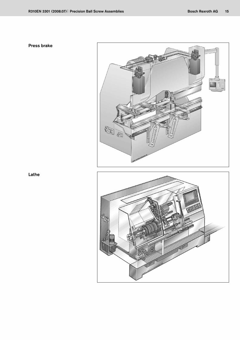
Lathe
Press brake

16 Bosch Rexroth AG Precision Ball Screw Assemblies R310EN 3301 (2008.07)
Inquiries and Orders
All nuts, screws and end machining de-tails can now be defined with the order code (up to screw diameter 80 mm) as a complete precision ball screw assembly. We have taken account of all former selection criteria as well as adding new ones. The diversity of possible combina-tions is limitless.
Attention is focused in particular on the definition of end machining details. For many design versions there is a prepared definition, providing you with a suitable solution for practically every application.
If you wish to send us an inquiry, simply complete the form at the end of this catalog. If no drawing is available, please specify your wishes using the variable order code. You will find a summary of the options on page 19.
Should you already have a drawing avail-able as a CAD file in Pro/E, AutoCAD, STEP or DXF, you can send us the data by e-mail to [email protected].
If the drawing exists on paper only, you can, of course, send it to us by conven-tional mail.
Each customer-specific precision ball screw assembly is issued with an ID number when an order is placed. If you have any subsequent queries, you need only quote this ID number.
Using the ordering data from the cata-log, you can also easily generate a drawing in AutoCAD format via the functionality provided on our website. A guided dialogue is provided for data input so as to avoid typing errors, and all data selected can be checked within a few minutes against the drawing that has been generated. This drawing can then be used directly by our production departments, which accelerates order processing and delivery. The drawing generation functionality can be used without registering with us or entering a password or customer number.To access this functionality, visit http://www.boschrexroth.com/ball_screws.
From there, you can access the on-line catalog via the link “CAD files: Select individual types” in the right navigation bar. The menu “Ball screw assemblies” on the left brings you to the desired goal.
Data can be input in two ways. In the default mode, “Configuration of options”, the dialog is supported by meaningful default settings to minimize input errors. The “Expert configuration” mode allows much more rapid input of data, but re-quires a certain amount of experience. When the dialogue is completed, a click on the “CAD-Model” button leads to a further dialog box asking for input of the e-mail address for electronic transmis-sion of the drawing to the user.
Registered customers based in Germany can use further eShop functions such as the shopping cart, the inquiry list and order status and can receive direct offers for the inquired precision ball screw assemblies or check the delivery status of current orders.
Inquiries and Orders

17Bosch Rexroth AG
2,21 5
86
121620253240506380
5 10 12 16 20 25 32 40
Precision Ball Screw AssembliesR310EN 3301 (2008.07)
The ordering data given on page 20 covers all the parameters of a precision ball screw assembly. Once you have defined the nominal diameter and lead and entered the total length, the functionality guides you through a succession of dialog boxes allowing you to select the desired options.
Nominal diameters, leads
Overall length Ltot of a precision ball screw assembly
Overall length Ltot
Lead P
Nom
inal
dia
met
er d
0

18 Bosch Rexroth AG Precision Ball Screw Assemblies R310EN 3301 (2008.07)
Inquiries and Orders
Nut typeThe various series versions and forms are shown below.
Mounting direction of nut typesDefinition: The centering diameter on a nut with flange, the slotted nut on a driven nut and the lube bore on a cylindrical nut points to the right end of the screw.
ZEM-E-S Cylindrical single nutStandard series
FEM-E-C Single nut with flangeDIN 69 051, Part 5
Standard series
FDM-E-C Double nut with flangeDIN 69 051, Part 5
Standard series
SEM-E-C Adjustable-preloadsingle nut, DIN 69 051, Part 5
Standard series
FEM-E-S Single nut with flangeStandard series
SEM-E-S Adjustable-preloadsingle nut, Standard series
FDM-E-S Double nut with flangeStandard series
FEM-E-B Single nut with flangeMiniature series
FEP-E-S Single nut with flangeSpeed series
FBZ-E-S Single nut with flange ECO series
FSZ-E-S Single nut with flangeECOplus series
Page 32
Page 36Page 34
Page 38 Page 40
Page 42 Page 44
Page 22 Page 24
Page 30
Page 26 Page 28
FAR-B-SFor driven nuts, please refer to
catalog R310EN 3304
Centering diameter D1
Lube port
Slotted nut
Driven nut
Centering diameter D1
Lube port
ZEV-E-S Screw-in nutECO series
Page 46
2-start FED-E-B single nut with flange

19Bosch Rexroth AGPrecision Ball Screw AssembliesR310EN 3301 (2008.07)
Screw ends, forms for a left or right screw end
Basic version With keyway Cut to size only “T”
00 Page 56 00 Page 56
01 Page 58 02 Page 58
11 Page 60 12 Page 60
21 Page 62
31 Page 64
41 Page 66
End mechanically connected with/without keyway
51 Page 68 53 Page 68
61 Page 70 62 Page 70
71 Page 72 72 Page 72
81 Page 74 82 Page 74 8384
Page 76
91 Page 78 92 Page 78 9394
Page 80
Machining of end face Z Centering hole DIN 332-D S Hex socket

20 Bosch Rexroth AG Precision Ball Screw Assemblies R310EN 3301 (2008.07)
Inquiries and Orders
Ordering Code
Precision Ball Screw Assembly
Nut typeFEM-E-B Single nut with flange Miniature seriesZEV-E-S Screw-in nut ECO seriesFBZ-E-S Single nut with flange ECO series FSZ-E-S Single nut with flange ECOplus series FEP-E-S Single nut with flange Speed seriesFEM-E-C Single nut with flange per DIN 69 051, Part 5FEM-E-S Single nut with flange, Rexroth mounting dimensionsSEM-E-C Adjustable-preload single nut per DIN 69 051, Part 5SEM-E-S Adjustable-preload single nut, Rexroth mounting dim.ZEM-E-S Cylindrical single nut, Rexroth mounting dimensionsFED-E-B 2-start single nut with flangeFDM-E-C Double nut with flange per DIN 69 051, Part 5FDM-E-S Double nut with flange, Rexroth mounting dimensions
SEM-E-S 20 x 5R x 3-4 1 2 T7 R 81Z120 41Z120 1250 1 1
Right screw end
Overall length Ltot (mm)
Seal
Preload
Precision
Screw
Documentation
Lubrication
Left screw end
Size
Order form: see page 131.Note: It is also possible to process inquiries based on a customer’s drawings.
only for d0 25 to 40; note higher frictional torque!only for d0 16 to 80
1)2)
0 … none 21)… reinforced seal1 … standard seal
0 … standard backlash 4 … 10% (double nut)1 … reduced backlash 5 … 7% (double nut)22)… 5% (single nut) 6 … 3% (single nut)3 … 2% (single nut) standard
T5, T7, T9 (T3 available upon request)
R … precision-rolled screw
0 … standard (acceptance test report) 2 … torque test report – is always supplied 3 … lead and torque test report1 … lead test report
0 … preserved 1 … preserved and nut with basic greasing
see left screw end
Nominal diameter (mm)Lead (mm)Direction of lead R … right, L … leftBall diameter (mm)Number of ball track turns in the nut
Form Z … centering per DIN 332-DOption S … hex socket K … noneVersion
Complete ball screw assembly with screw and nut

21Bosch Rexroth AGPrecision Ball Screw AssembliesR310EN 3301 (2008.07)
For screws supplied separately; cut to size only “T”
For special servicing cases involved precision-rolled screw SN-R with annealed ends, please consult us.
150 annealed 80 annealed1250 overall length
For separately supplied screws with annealed ends (special servicing cases)
Screw
Screw designation
SN 20 x 5R x 3 X X T7 R 00T200 00T200 1250 0 0
Right screw end
Overall length Ltot (mm)
Seal
Preload
Precision
Screw
Documentation
Lubrication
Left screw end
Size
X … not possible
X … not possible
T5, T7, T9
R … precision-rolled screw
0 … standard (acceptance test report)1 … lead test report
0 … preserved
see left screw end
Nominal diameter (mm)Lead (mm)Direction of lead R … right, L … leftBall diameter (mm)
FormOption T … cut to size onlyVersion
Order form: see page 131.Note: It is also possible to process inquiries based on a customer’s drawings.

22 Bosch Rexroth AG Precision Ball Screw Assemblies R310EN 3301 (2008.07)
Miniature Single Nut with Flange FEM-E-B
Rexroth mounting dimensionsFlange type B
With sealsWith backlash or reduced backlashFor precision-rolled screws SN-Rof tolerance grade T5, T7
Supplied only as complete ball screw assembly.
Miniature series
Nuts
d0 = nominal diameterP = lead (R = right-hand, L = left-hand)DW = ball diameter i = number of ball track turns
Ordering code:
Category Size Part number Load ratings Linear speed1)
d0 x P x DW - idyn. C
(N)stat. C0
(N)vmax
(m/min)A 6 x 1R x 0.8 - 4 R1532 100 06 900 1290 3A 6 x 2R x 0.8 - 4 R1532 120 06 890 1280 6A 8 x 1R x 0.8 - 4 R1532 200 06 1020 1740 3A 8 x 2R x 1.2 - 4 R1532 220 06 1870 2760 6A 8 x 2.5R x 1.588 - 3 R1532 230 06 2200 2800 15A 12 x 2R x 1.2 - 4 R1532 420 06 2240 4160 12A 12 x 5R x 2 - 3 R1532 460 06 3800 5800 30A 12 x 10R x 2 - 2 R1532 490 06 2500 3600 60
See page 101 Characteristic speed d0 · n and page 124 Critical speed ncr1)
FEM-E-B 6 x 2R x 0.8-4 1 1 T7 R 83K060 41K050 250 0 1

23Bosch Rexroth AG
L4
L
L3
D7
D6
D1
L 14
Dw
d0
d 1
d 2
D5
L7
2
30°
30°
Precision Ball Screw AssembliesR310EN 3301 (2008.07)
Lube port
Size Dimensions (mm) Weight
d0 x P x DW - id1 d2 D1
g6D5 D6 D7 L L3 L4 L7 L14 m
(kg)6 x 1R x 0.8 - 4 6.0 5.3 12 24 18 3.4 19.5 3.5 16 3.5 16 0.0206 x 2R x 0.8 - 4 6.0 5.3 12 24 18 3.4 22.5 3.5 19 3.0 16 0.0208 x 1R x 0.8 - 4 8.0 7.3 16 28 22 3.4 22.0 6.0 16 3.5 19 0.0358 x 2R x 1.2 - 4 8.0 7.0 16 28 22 3.4 25.0 6.0 19 3.0 19 0.0508 x 2.5R x 1.588 - 3 7.5 6.3 16 28 22 3.4 16.0 6.0 10 3.0 19 0.03012 x 2R x 1.2 - 4 11.7 10.8 20 37 29 4.5 19.0 8.0 11 2.5 24 0.05512 x 5R x 2 - 3 11.4 9.9 22 37 29 4.5 28.0 8.0 20 6.0 24 0.07512 x 10R x 2 - 2 11.4 9.9 22 37 29 4.5 33.0 8.0 25 8.0 24 0.085

24 Bosch Rexroth AG
ZEV-E-S 20 x 5R x 3-4 0 0 T7 R 81K120 41K120 550 0 0
Precision Ball Screw Assemblies R310EN 3301 (2008.07)
Screw-in Nut ZEV-E-SECO seriesRexroth mounting dimensions
Without seals (no initial greasing)Seals available on requestWith backlashFor precision-rolled screws SN-Rof tolerance grade T7, T9
Supplied only as complete ball screw assembly.
d0 = nominal diameterP = lead (R = right-hand, L = left-hand)DW = ball diameter i = number of ball track turns
Ordering code:
Category Size Part number Load ratings Linear speed1)
d0 x P x DW - idyn. C
(N)stat. C0
(N)vmax
(m/min)A 12 x 5R x 2 - 3 R2542 430 01 2300 3500 30.0A 12 x 10R x 2 - 2 R2542 430 11 1500 2200 60.0A 16 x 5R x 3 - 3 R2542 000 01 5600 7100 25.0A 16 x 10R x 3 - 3 R2542 000 11 5800 7400 50.0A 20 x 5R x 3 - 4 R2542 100 01 8600 12900 20.0A 25 x 5R x 3 - 7 R2542 200 01 15700 29200 16.0A 25 x 10R x 3 - 5 R2542 200 11 11500 20500 32.0A 32 x 5R x 3.5 - 5 R2542 300 01 15800 30400 12.5A 32 x 10R x 3.969 - 5 R2542 300 11 19000 34700 25.0
See page 101 Characteristic speed d0 · n and page 124 Critical speed ncr1)
Nuts

25Bosch Rexroth AG
L15
L
D1
Dw
d 0d 1d 2
1G
L7
D8D4
Precision Ball Screw AssembliesR310EN 3301 (2008.07)
Lube port Bore for assembly wrench
Size Dimensions (mm) Max. Weight
d0 x P x DW - id1 d2 D1
h10D4 D8 G1 L
±0.3L7 L15 backlash
(mm)m
(kg)12 x 5R x 2 - 3 11.4 9.9 25.5 2.7 3.2 M20 x 1.0 36 8.5 10 0.1 0.0912 x 10R x 2 - 2 11.4 9.9 25.5 2.7 3.2 M20 x 1.0 40 8.5 10 0.1 0.1016 x 5R x 3 - 3 15.0 12.9 32.5 2.7 4.2 M26 x 1.5 40 10.5 12 0.1 0.1416 x 10R x 3 - 3 15.0 12.9 32.5 2.7 4.2 M26 x 1.5 54 10.5 12 0.1 0.2120 x 5R x 3 - 4 19.0 16.9 38.0 2.7 8.0 M35 x 1.5 50 12.5 14 0.1 0.2525 x 5R x 3 - 7 24.0 21.9 43.0 1.5 8.0 M40 x 1.5 60 17.5 19 0.1 0.3625 x 10R x 3 - 5 24.0 21.9 43.0 2.0 8.0 M40 x 1.5 74 17.7 19 0.1 0.4532 x 5R x 3.5 - 5 31.0 28.4 54.0 2.7 8.0 M48 x 1.5 69 17.5 19 0.1 0.5832 x 10R x 3.969 - 5 31.0 27.9 54.0 2.7 8.0 M48 x 1.5 95 17.5 19 0.1 0.88
26 Bosch Rexroth AG
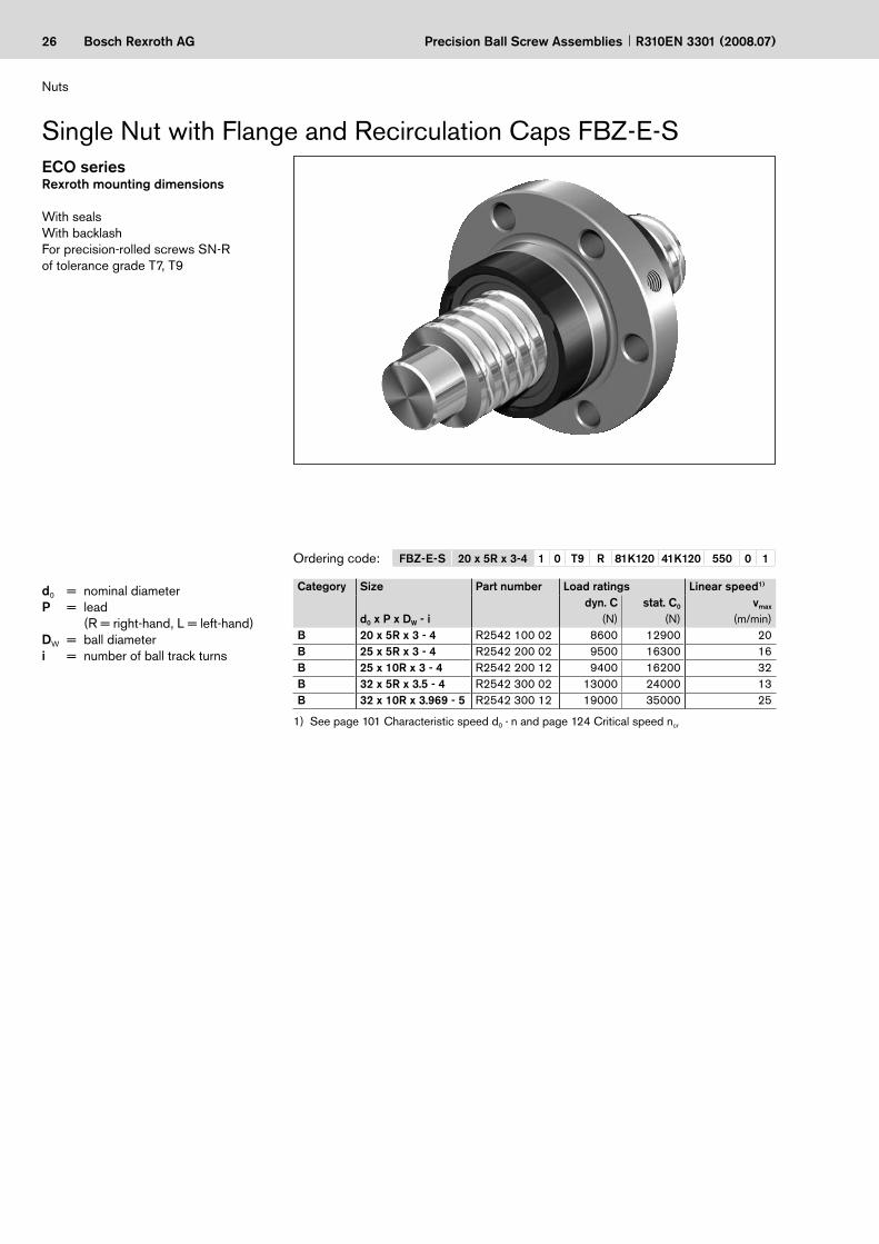
FBZ-E-S 20 x 5R x 3-4 1 0 T9 R 81K120 41K120 550 0 1
Precision Ball Screw Assemblies R310EN 3301 (2008.07)
d0 = nominal diameterP = lead (R = right-hand, L = left-hand)DW = ball diameter i = number of ball track turns
Ordering code:
Category Size Part number Load ratings Linear speed1)
d0 x P x DW - idyn. C
(N)stat. C0
(N)vmax
(m/min)B 20 x 5R x 3 - 4 R2542 100 02 8600 12900 20B 25 x 5R x 3 - 4 R2542 200 02 9500 16300 16B 25 x 10R x 3 - 4 R2542 200 12 9400 16200 32B 32 x 5R x 3.5 - 4 R2542 300 02 13000 24000 13B 32 x 10R x 3.969 - 5 R2542 300 12 19000 35000 25
See page 101 Characteristic speed d0 · n and page 124 Critical speed ncr1)
Rexroth mounting dimensions
With sealsWith backlashFor precision-rolled screws SN-Rof tolerance grade T7, T9
Single Nut with Flange and Recirculation Caps FBZ-E-SECO series
Nuts

27Bosch Rexroth AG
6x60
° 3
0° D 6
L 5
LK
L 3
L
D K
D w
d 0
d 1
d 2
M6
6,6
L 10
5 D
D K
D 1
D 1
LK
Precision Ball Screw AssembliesR310EN 3301 (2008.07)
Size Dimensions (mm) Max. Weight
d0 x P x DW - id1 d2 D1
–0.2D5 D6 DK L L3 L5
±0.5L10 LK backlash
(mm)m
(kg)20 x 5R x 3 - 4 19 16.9 33 58 45 32.5 40 10 15.0 15.0 8.5 0.1 0.2225 x 5R x 3 - 4 24 21.9 38 63 50 37.5 43 10 16.5 16.5 10.0 0.1 0.2525 x 10R x 3 - 4 24 21.9 38 63 50 37.5 62 10 16.0 36.0 10.0 0.1 0.3432 x 5R x 3.5 - 4 31 28.4 48 73 60 47.5 46 12 17.0 17.0 11.0 0.1 0.4132 x 10R x 3.969 - 5 31 27.9 48 73 60 47.5 77 12 20.0 45.0 11.0 0.1 0.63
Plastic recirculation cap at both ends
Undercut for mounting
Lube port at flange center

28 Bosch Rexroth AG
FSZ-E-S 20 x 5R x 3-4 1 0 T7 R 81K120 41K120 550 0 1
Precision Ball Screw Assemblies R310EN 3301 (2008.07)
d0 = nominal diameterP = lead (R = right-hand, L = left-hand)DW = ball diameter i = number of ball track turns
Ordering code:
Category Size Part number Load ratings Linear speed1)
d0 x P x DW - idyn. C
(N)stat. C0
(N)vmax
(m/min)A 20 x 5R x 3 - 4 R1502 110 41 14300 21500 30A 25 x 5R x 3 - 4 R1502 210 41 15900 27200 30A 25 x 10R x 3 - 4 R1502 240 41 15700 27000 60A 32 x 5R x 3.5 - 4 R1502 310 41 21600 40000 23A 32 x 10R x 3.969 - 5 R1502 340 41 31700 58300 47A 32 x 20R x 3.969 - 2 R1502 370 41 13500 21800 94A 40 x 5R x 3.5 - 5 R1502 410 41 29100 64100 19A 40 x 10R x 6 - 4 R1502 440 41 50000 86400 38A 40 x 20R x 6 - 3 R1502 470 41 37900 62800 75
See page 101 Characteristic speed d0 · n and page 124 Critical speed ncr1)
Single Nut with Flange and Recirculation Caps FSZ-E-S
Rexroth mounting dimensions
ECOplus load ratings in accordance with Standard series (see page 36)With sealsWith backlash, reduced backlash, preload 2%; 3%; 5%For precision-rolled screws SN-R of tolerance grade T5, T7, T9
ECOplus series
Nuts

29Bosch Rexroth AG
6x60
°
30
°
D6
L5 L4L3
L
LKLK
DK
DKD1
Dw
d 0d 1d 2
S
D7
L10
5D
D –
0,05
1 –0
,1
D+
0,7
1
Precision Ball Screw AssembliesR310EN 3301 (2008.07)
Size Dimensions (mm) Weight
d0 x P x DW - id1 d2 D1
g6D5 D6 D7 DK L
±0.5L3 L4 L5 L10 LK S m
(kg)20 x 5R x 3 - 4 19 16.9 33 58 45 6.6 32.5 40 10 6 15.0 15.0 8.5 M6 0.2225 x 5R x 3 - 4 24 21.9 38 63 50 6.6 37.5 43 10 6 16.5 16.5 10.0 M6 0.2525 x 10R x 3 - 4 24 21.9 38 63 50 6.6 37.5 62 10 16 16.0 36.0 10.0 M6 0.3432 x 5R x 3.5 - 4 31 28.4 48 73 60 6.6 47.5 46 12 6 17.0 17.0 11.0 M6 0.4132 x 10R x 3.969 - 5 31 27.9 48 73 60 6.6 47.5 77 12 16 20.0 45.0 11.0 M6 0.6332 x 20R x 3.969 - 2 31 27.9 56 80 68 6.6 47.5 65 12 10 19.0 34.0 11.0 M6 0.6940 x 5R x 3.5 - 5 39 36.4 56 80 68 6.6 55.5 52 14 8 18.5 19.5 11.5 M8x1 0.5440 x 10R x 6 - 4 38 33.8 63 95 78 9.0 62.5 71 14 16 22.0 35.0 12.5 M8x1 1.0640 x 20R x 6 - 3 38 33.8 63 95 78 9.0 62.5 89 14 25 22.0 53.0 12.5 M8x1 1.30
Plastic recirculation cap
Plastic recirculation cap
Lube port at flange center

30 Bosch Rexroth AG Precision Ball Screw Assemblies R310EN 3301 (2008.07)
d0 = nominal diameterP = lead (R = right-hand, L = left-hand)DW = ball diameteri = a x b “a” Bearing turns per thread“b” Number of bearing threads
on the screw
Ordering code:
Category Size Part number Load ratings Linear speed1)
d0 x P x DW - idyn. C
(N)stat. C0
(N)vmax
(m/min)A 20 x 40R x 3.5 - 1 x 4 R2522 100 11 14000 26200 240A 25 x 25R x 3.5 - 1.2 x 4 R2522 200 01 19700 39400 120A 32 x 32R x 3.969 - 1.2 x 4 R2522 300 01 26300 57600 120
See page 101 Characteristic speed d0 · n and page 124 Critical speed ncr1)
Single Nut with Flange and Recirculation Caps FEP-E-S
Rexroth mounting dimensions
With sealsWith backlash, reduced backlash or preload 2%For precision-rolled screws SN-R (4-start) of tolerance grade T5, T7, T9
Speed series
Nuts
FEP-E-S 25 x 25R x 3.5-1.2x4 1 0 T5 R 81K120 41K120 1100 0 1

31Bosch Rexroth AG
6x60
°
30
°D6
LK
L4L3
L
LK
DK
DKD1
Dw
d 0d 1d 2
M6
6,6
D5
L8
Precision Ball Screw AssembliesR310EN 3301 (2008.07)
Plastic recirculation cap
Plastic recirculation cap
Lube port
Size Dimensions (mm) Weight
d0 x P x DW - id1 d2 D1
g6D5 D6 DK L
±0.5L3 L4 L8 LK m
(kg) 20 x 40R x 3.5 - 1 x 4 19 16.4 38 63 50 37.5 57 12 23 8.0 11 0.5125 x 25R x 3.5 - 1.2 x 4 24 21.4 48 73 60 40.0 52 12 14 5.0 13 0.5132 x 32R x 3.969 - 1.2 x 4 31 27.9 56 80 68 50.0 68 15 21 7.7 16 0.78

32 Bosch Rexroth AG
FEM-E-C 20 x 5R x 3-4 1 2 T7 R 82Z120 41Z120 1250 0 1
Precision Ball Screw Assemblies R310EN 3301 (2008.07)
d0 = nominal diameterP = lead (R = right-hand, L = left-hand)DW = ball diameter i = number of ball track turns
Ordering code:
See page 101 Characteristic speed d0 · n and page 124 Critical speed ncr
Nuts 80 x 20R x 12.7 - 6 available up to a thread length of 2500 mm, with preload1)2)
Single Nut with Flange FEM-E-C
Mounting dimensions per DIN 69 051, Part 5Flange type C
With standard sealsReinforced seals, see page 112With backlash, reduced backlash, preload 2%; 3%; 5%For precision-rolled screws SN-R of tolerance grade T5, T7, T9
Standard series
Category Size Part number Load ratings Linear speed1)
d0 x P x DW - idyn. C
(N)stat. C0
(N)vmax
(m/min)A 16 x 5R x 3 - 4 R1502 010 65 12300 16100 30A 16 x 10R x 3 - 3 R1502 040 85 9600 12300 60A 16 x 16R x 3 - 3 R1502 060 65 9300 12000 96A 20 x 5R x 3 - 4 R1502 110 85 14300 21500 30A 20 x 20R x 3.5 - 3 R1502 170 65 13300 18800 120A 25 x 5R x 3 - 4 R1502 210 85 15900 27200 30A 25 x 10R x 3 - 4 R1502 240 85 15700 27000 60A 25 x 25R x 3.5 - 3 R1502 280 65 14700 23300 150A 32 x 5R x 3.5 - 4 R1502 310 85 21600 40000 23A 32 x 10R x 3.969 - 5 R1502 340 86 31700 58300 47A 32 x 20R x 3.969 - 3 R1502 370 65 19700 33700 94A 32 x 32R x 3.969 - 3 R1502 390 65 19500 34000 150B 40 x 5R x 3.5 - 5 R1502 410 86 29100 64100 19A 40 x 10R x 6 - 4 R1502 440 85 50000 86400 38C 40 x 12R x 6 - 4 R1502 450 65 49900 86200 45A 40 x 16R x 6 - 4 R1502 460 65 49700 85900 60A 40 x 20R x 6 - 3 R1502 470 85 37900 62800 75A 40 x 40R x 6 - 3 R1502 490 65 37000 62300 150B 50 x 5R x 3.5 - 5 R1502 510 86 32000 81300 15A 50 x 10R x 6 - 6 R1502 540 86 79700 166500 30C 50 x 12R x 6 - 6 R1502 550 66 79600 166400 36B 50 x 16R x 6 - 6 R1502 560 66 79400 166000 48A 50 x 20R x 6.5 - 5 R1502 570 86 75700 149700 60B 50 x 40R x 6.5 - 3 R1502 590 65 46500 85900 120B 63 x 10R x 6 - 6 R1502 640 86 88800 214300 24B 63 x 20R x 6.5 - 5 R1502 670 86 83900 190300 48C 63 x 40R x 6.5 - 3 R1502 690 65 53400 114100 95C 80 x 10R x 6.5 - 6 R1502 740 86 108400 291700 19B 80 x 20R x 12.7 - 62) R1502 770 96 262700 534200 30
Nuts

33Bosch Rexroth AG
90°
L4
LL3
22,5°
90°
30°
30°
D7
D7
SS
D6
D6
D1D5
L 9L 9
D wd 0d 1d 2
L10
–0,0
5–0
,1D
1
BB1
BB2
Precision Ball Screw AssembliesR310EN 3301 (2008.07)
Size Dimensions (mm) Weight
d0 x P x DW - id1 d2 D1
g6D5 Hole
patternD6 D7 L L3 L4 L9 L10 S3) m
(kg)16 x 5R x 3 - 4 15.0 12.9 28 48 BB2 38 5.5 38 12 10 44.0 26 M6 0.1916 x 10R x 3 - 3 15.0 12.9 28 48 BB2 38 5.5 45 12 16 44.0 33 M6 0.2116 x 16R x 3 - 3 15.0 12.9 28 48 BB2 38 5.5 61 12 20 44.0 49 M6 0.2620 x 5R x 3 - 4 19.0 16.9 36 58 BB2 47 6.6 40 12 10 51.0 28 M6 0.3120 x 20R x 3.5 - 3 19.3 16.7 36 58 BB2 47 6.6 77 12 25 51.0 65 M6 0.4925 x 5R x 3 - 4 24.0 21.9 40 62 BB2 51 6.6 45 12 10 55.0 33 M6 0.3625 x 10R x 3 - 4 24.0 21.9 40 62 BB2 51 6.6 64 12 16 55.0 52 M6 0.4725 x 25R x 3.5 - 3 24.0 21.4 40 62 BB2 51 6.6 95 12 30 55.0 83 M6 0.6332 x 5R x 3.5 - 4 31.0 28.4 50 80 BB2 65 9.0 48 13 10 71.0 35 M6 0.6232 x 10R x 3.969 - 5 31.0 27.9 50 80 BB2 65 9.0 77 13 16 71.0 64 M6 0.8432 x 20R x 3.969 - 3 31.0 27.9 50 80 BB2 65 9.0 84 13 25 71.0 71 M6 0.9032 x 32R x 3.969 - 3 31.0 27.9 50 80 BB2 65 9.0 120 13 40 71.0 107 M6 1.2140 x 5R x 3.5 - 5 39.0 36.4 63 93 BB1 78 9.0 54 15 10 81.5 39 M8x1 1.0340 x 10R x 6 - 4 38.0 33.8 63 93 BB1 78 9.0 70 15 16 81.5 55 M8x1 1.1940 x 12R x 6 - 4 38.0 33.8 63 93 BB1 78 9.0 75 15 25 81.5 60 M8x1 1.2740 x 16R x 6 - 4 38.0 33.8 63 93 BB1 78 9.0 90 15 25 81.5 75 M8x1 1.5140 x 20R x 6 - 3 38.0 33.8 63 93 BB1 78 9.0 88 15 25 81.5 73 M8x1 1.4440 x 40R x 6 - 3 38.0 33.8 63 93 BB1 78 9.0 142 15 45 81.5 127 M8x1 2.1650 x 5R x 3.5 - 5 49.0 46.4 75 110 BB1 93 11.0 54 15 10 97.5 39 M8x1 1.3950 x 10R x 6 - 6 48.0 43.8 75 110 BB1 93 11.0 90 18 16 97.5 72 M8x1 2.1450 x 12R x 6 - 6 48.0 43.8 75 110 BB1 93 11.0 105 18 25 97.5 87 M8x1 2.3850 x 16R x 6 - 6 48.0 43.8 75 110 BB1 93 11.0 128 18 25 97.5 110 M8x1 2.7550 x 20R x 6.5 - 5 48.0 43.4 75 110 BB1 93 11.0 132 18 25 97.5 114 M8x1 2.7350 x 40R x 6.5 - 3 48.0 43.4 75 110 BB1 93 11.0 149 18 45 97.5 131 M8x1 3.0463 x 10R x 6 - 6 61.0 56.8 90 125 BB1 108 11.0 90 22 16 110.0 68 M8x1 2.5663 x 20R x 6.5 - 5 61.0 56.4 95 135 BB1 115 13.5 132 22 25 117.5 110 M8x1 4.5163 x 40R x 6.5 - 3 61.0 56.4 95 135 BB1 115 13.5 149 22 45 117.5 127 M8x1 5.0480 x 10R x 6.5 - 6 78.0 73.3 105 145 BB1 125 13.5 95 22 16 127.5 73 M8x1 3.4080 x 20R x 12.7 - 6 76.0 67.0 125 165 BB1 145 13.5 170 25 25 147.5 145 M8x1 10.20
d0 ≤ 32
d0 ≥ 40
Lube port at flange center3)
Lube port machining: flat surface L3 ≤ 13 mm, countersink L3 > 14 mm3)

34 Bosch Rexroth AG
SEM-E-C 20 x 5R x 3-4 1 2 T7 R 82Z120 41Z120 1250 0 1
Precision Ball Screw Assemblies R310EN 3301 (2008.07)
d0 = nominal diameterP = lead (R = right-hand, L = left-hand)DW = ball diameter i = number of ball track turns Ordering code:
Category Size Part number Load ratings Linear speed1)
vmax
(m/min)
Centering diameter D1
after adjustmentdyn. C stat. C0
d0 x P x DW - i (N) (N) min. (mm) max. (mm)B 16 x 5R x 3 - 4 R1512 010 55 12300 16100 30 27.940 27.975C 16 x 10R x 3 - 3 R1512 040 75 9600 12300 60 27.940 27.975C 16 x 16R x 3 - 3 R1512 060 55 9300 12000 96 27.950 27.978B 20 x 5R x 3 - 4 R1512 110 75 14300 21500 30 35.935 35.970B 20 x 20R x 3.5 - 3 R1512 170 55 13300 18800 120 35.945 35.973B 25 x 5R x 3 - 4 R1512 210 75 15900 27200 30 39.935 39.970B 25 x 10R x 3 - 4 R1512 240 75 15700 27000 60 39.935 39.970C 25 x 25R x 3.5 - 3 R1512 280 55 14700 23300 150 39.945 39.973B 32 x 5R x 3.5 - 4 R1512 310 75 21600 40000 23 49.935 49.970B 32 x 10R x 3.969 - 5 R1512 340 75 31700 58300 47 49.935 49.970C 32 x 20R x 3.969 - 3 R1512 370 55 19700 33700 94 49.945 49.973B 32 x 32R x 3.969 - 3 R1512 390 55 19500 34000 150 49.945 49.973B 40 x 5R x 3.5 - 5 R1512 410 75 29100 64100 19 62.931 62.966B 40 x 10R x 6 - 4 R1512 440 75 50000 86400 38 62.931 62.966C 40 x 12R x 6 - 4 R1512 450 55 49900 86200 45 62.931 62.966B 40 x 20R x 6 - 3 R1512 470 75 37900 62800 75 62.941 62.969B 40 x 40R x 6 - 3 R1512 490 55 37000 62300 150 62.941 62.969C 50 x 5R x 3.5 - 5 R1512 510 75 32000 81300 15 74.931 74.966B 50 x 10R x 6 - 6 R1512 540 75 79700 166500 30 74.931 74.966C 50 x 12R x 6 - 6 R1512 550 55 79600 166400 36 74.931 74.966B 50 x 20R x 6.5 - 5 R1512 570 76 75700 149700 60 74.941 74.969B 50 x 40R x 6.5 - 3 R1512 590 55 46500 85900 120 74.941 74.969B 63 x 10R x 6 - 6 R1512 640 75 88800 214300 24 89.926 89.961B 63 x 20R x 6.5 - 5 R1512 670 76 83900 190300 48 94.936 94.964C 63 x 40R x 6.5 - 3 R1512 690 55 53400 114100 95 94.936 94.964C 80 x 10R x 6.5 - 6 R1512 740 75 108400 291700 19 104.926 104.961C 80 x 20R x 12.7 - 62) R1512 770 56 262700 534200 30 124.931 124.959
Mounting dimensions per DIN 69 051, Part 5Flange type C
With standard sealsReinforced seals, see page 112Adjustable preloadFor precision-rolled screws SN-R of tolerance grade T5, T7
Adjustable-Preload Single Nut SEM-E-CStandard series
See page 101 Characteristic speed d0 · n and page 124 Critical speed ncr
Nuts 80 x 20R x 12.7 - 6 available up to a thread length of 2500 mm, with preload1)2)
Nuts

35Bosch Rexroth AG
L10
L3 L4
L
90°
22,5°30°
30°
90°
L8
S
D6
D6
SD7
D7
1D
+0,
7
D5
L 9L 9
L5
D1
–0,0
5–0
,1Dw
d 0d 1d 21
D
Precision Ball Screw AssembliesR310EN 3301 (2008.07)
Size Dimensions (mm) Weight
d0 x P x DW - id1 d2 D1
f9D5 Hole
patternD6 D7 L L3 L4 L5 L8 L9 L10 S3) m
(kg)16 x 5R x 3 - 4 15.0 12.9 28 48 BB2 38 5.5 38 15 10 11.5 7.1 44.0 11.5 M6 0.2016 x 10R x 3 - 3 15.0 12.9 28 48 BB2 38 5.5 45 15 15 15.0 11.0 44.0 15.0 M6 0.2216 x 16R x 3 - 3 15.0 12.9 28 48 BB2 38 5.5 61 15 20 23.0 10.0 44.0 23.0 M6 0.2920 x 5R x 3 - 4 19.0 16.9 36 58 BB2 47 6.6 40 15 10 12.5 7.1 51.0 12.5 M6 0.3320 x 20R x 3.5 - 3 19.3 16.7 36 58 BB2 47 6.6 77 20 25 28.5 12.5 51.0 28.5 M6 0.5625 x 5R x 3 - 4 24.0 21.9 40 62 BB2 51 6.6 45 20 10 12.5 9.5 55.0 12.5 M6 0.4325 x 10R x 3 - 4 24.0 21.9 40 62 BB2 51 6.6 64 20 16 22.0 10.0 55.0 22.0 M6 0.5425 x 25R x 3.5 - 3 24.0 21.4 40 62 BB2 51 6.6 95 25 30 35.0 14.0 55.0 35.0 M6 0.7732 x 5R x 3.5 - 4 31.0 28.4 50 80 BB2 65 9.0 48 20 10 14.0 9.7 71.0 14.0 M6 0.7432 x 10R x 3.969 - 5 31.0 27.9 50 80 BB2 65 9.0 77 20 16 28.5 12.5 71.0 28.5 M6 0.9732 x 20R x 3.969 - 3 31.0 27.9 50 80 BB2 65 9.0 84 20 25 32.0 12.5 71.0 32.0 M6 1.0432 x 32R x 3.969 - 3 31.0 27.9 50 80 BB2 65 9.0 120 20 40 50.0 12.5 71.0 50.0 M6 1.3440 x 5R x 3.5 - 5 39.0 36.4 63 93 BB1 78 9.0 54 25 10 14.5 12.0 81.5 14.5 M8x1 1.2540 x 10R x 6 - 4 38.0 33.8 63 93 BB1 78 9.0 70 25 16 22.5 11.8 81.5 22.5 M8x1 1.3940 x 12R x 6 - 4 38.0 33.8 63 93 BB1 78 9.0 75 25 25 25.0 12.5 81.5 25.0 M8x1 1.4740 x 20R x 6 - 3 38.0 33.8 63 93 BB1 78 9.0 88 25 25 31.5 16.5 81.5 31.5 M8x1 1.5540 x 40R x 6 - 3 38.0 33.8 63 93 BB1 78 9.0 142 40 45 51.0 25.0 81.5 51.0 M8x1 2.6950 x 5R x 3.5 - 5 49.0 46.4 75 110 BB1 93 11.0 54 25 10 14.5 12.0 97.5 14.5 M8x1 1.6750 x 10R x 6 - 6 48.0 43.8 75 110 BB1 93 11.0 90 30 16 30.0 14.1 97.5 30.0 M8x1 2.4650 x 12R x 6 - 6 48.0 43.8 75 110 BB1 93 11.0 105 30 25 37.5 15.0 97.5 37.5 M8x1 2.6950 x 20R x 6.5 - 5 48.0 43.4 75 110 BB1 93 11.0 132 30 25 51.0 20.0 97.5 51.0 M8x1 3.0850 x 40R x 6.5 - 3 48.0 43.4 75 110 BB1 93 11.0 149 30 45 59.5 18.0 97.5 59.5 M8x1 3.3963 x 10R x 6 - 6 61.0 56.8 90 125 BB1 108 11.0 90 30 16 30.0 14.0 110.0 30.0 M8x1 2.8363 x 20R x 6.5 - 5 61.0 56.4 95 135 BB1 115 13.5 132 30 25 51.0 20.0 117.5 51.0 M8x1 4.8663 x 40R x 6.5 - 3 61.0 56.4 95 135 BB1 115 13.5 149 30 45 59.5 18.0 117.5 59.5 M8x1 5.3680 x 10R x 6.5 - 6 78.0 73.3 105 145 BB1 125 13.5 95 30 16 32.5 14.0 127.5 32.5 M8x1 3.7380 x 20R x 12.7 - 6 76.0 67.0 125 165 BB1 145 13.5 170 50 25 60.0 24.0 147.5 60.0 M8x1 13.50
d0 ≤ 32
d0 ≥ 40
BB2
BB1
Lube port3)
Lube port machining: flat surface L3 ≤ 13 mm, countersink L3 > 14 mm3)

36 Bosch Rexroth AG
FEM-E-S 20 x 5R x 3-4 1 2 T7 R 82Z120 41Z120 1250 0 1
Precision Ball Screw Assemblies R310EN 3301 (2008.07)
d0 = nominal diameterP = lead (R = right-hand, L = left-hand)DW = ball diameter i = number of ball track turns
Ordering code:
See page 101 Characteristic speed d0 · n and page 124 Critical speed ncr
Can be replaced in these sizes by FSZ-E-SNuts 80 x 20R x 12.7 - 6 available up to a thread length of 2500 mm, with preload
1)
2)
3)
Rexroth mounting dimensions
With standard sealsWith left-hand thread in some versionsReinforced seals, see page 112With backlash, reduced backlash, preload 2%; 3%; 5%For precision-rolled screws SN-R of tolerance grade T5, T7, T9
Single Nut with Flange FEM-E-SStandard series
Nuts
Category Size Part number Load ratings Linear speed1)
d0 x P x Dw - idyn. C
(N)stat. C0
(N)vmax
(m/min)A 8 x 2.5R x 1.588 - 3 R1532 230 03 2200 2800 15A 12 x 5R x 2 - 3 R1532 460 23 3800 5800 30B 12 x 10R x 2 - 2 R1532 490 13 2500 3600 60A 16 x 5R x 3 - 4 R1512 010 23 12300 16100 30A 16 x 10R x 3 - 3 R1512 040 13 9600 12300 60B 16 x 16R x 3 - 2 R1512 060 13 6300 7600 96A2) 20 x 5R x 3 - 4 R1512 110 13 14300 21500 30B 20 x 5L x 3 - 4 R1552 110 13 14300 21500 30A 20 x 10R x 3 - 4 R1512 140 13 14100 21300 60A 20 x 20R x 3.5 - 2 R1512 170 13 9100 12100 120B 20 x 20L x 3.5 - 2 R1552 170 13 9100 12100 120A2) 25 x 5R x 3 - 4 R1512 210 13 15900 27200 30B 25 x 5 L x 3 - 4 R1552 210 13 15900 27200 30A2) 25 x 10R x 3 - 4 R1512 240 13 15700 27000 60A 25 x 25R x 3.5 - 2 R1512 280 13 10100 15100 150B 25 x 25 L x 3.5 - 2 R1552 280 13 10100 15100 150A2) 32 x 5R x 3.5 - 4 R1512 310 13 21600 40000 23A2) 32 x 10R x 3.969 - 5 R1512 340 13 31700 58300 47A2) 32 x 20R x 3.969 - 2 R1512 370 13 13500 21800 94A 32 x 32R x 3.969 - 2 R1512 390 13 13400 22000 150A 40 x 5R x 3.5 - 5 R1512 410 13 29100 64100 19A2) 40 x 10R x 6 - 4 R1512 440 13 50000 86400 38A2) 40 x 20R x 6 - 3 R1512 470 13 37900 62800 75A 40 x 40R x 6 - 2 R1512 490 13 25500 40300 150B 50 x 5R x 3.5 - 5 R1512 510 13 32000 81300 15A 50 x 10R x 6 - 6 R1512 540 13 79700 166500 30C 50 x 16R x 6 - 6 R1512 560 13 79400 166000 48B 50 x 20R x 6.5 - 3 R1512 570 13 47900 87900 60B 50 x 40R x 6.5 - 2 R1512 590 13 32100 55800 120A 63 x 10R x 6 - 6 R1512 640 13 88800 214300 24B 63 x 20R x 6.5 - 3 R1512 670 13 53200 112100 48C 63 x 40R x 6.5 - 2 R1512 690 13 36900 74300 95B 80 x 10R x 6.5 - 6 R1512 740 13 108400 291700 19B 80 x 20R x 12.7 - 63) R1512 770 23 262700 534200 30

37Bosch Rexroth AG
S
6x60
°
D6
L4L3L
L5
L4L3L
4x90
°
ϕ
S
D1
D5
D1+
0,7
D1
D1–0
,05
–0,1
L10
D w
d 0d 1d 2
S
D7
D6
D7
D6
8x45
°
D7
ϕ ϕ
BB3 BB4 BB5
BF1
BF2
Precision Ball Screw AssembliesR310EN 3301 (2008.07)
Lube port at flange center
Lube port4) at flange center
Lube port machining: flat surface L3 ≤ 13 mm, countersink L3 > 14 mm. For size 8 x 2.5, a funnel-type lube nipple DIN 3405 is provided.4)
Size Dimensions (mm) Weight
d0 x P x Dw - id1 d2 D1
g6D5 Hole
patternD6 D7 Type L L3 L4 L5 L10 S4) ϕ
(°)m
(kg)8 x 2.5R x 1.588 - 3 7.5 6.3 16 30 BB4 23 3.4 BF1 16 8 8.0 – 8 M4 30.0 0.0512 x 5R x 2 - 3 11.4 9.9 24 40 BB4 32 4.5 BF1 28 12 10.0 – 16 M6 330.0 0.1212 x 10R x 2 - 2 11.4 9.9 24 40 BB4 32 4.5 BF1 33 12 16.0 – 21 M6 330.0 0.1416 x 5R x 3 - 4 15.0 12.9 28 53 BB3 40 6.6 BF1 38 12 10.0 – 26 M6 315.0 0.2416 x 10R x 3 - 3 15.0 12.9 28 53 BB3 40 6.6 BF1 45 12 16.0 – 33 M6 315.0 0.2516 x 16R x 3 - 2 15.0 12.9 33 58 BB4 45 6.6 BF2 45 15 15.0 15.0 – M6 30.0 0.3920 x 5R x 3 - 4 19.0 16.9 33 58 BB4 45 6.6 BF1 40 12 10.0 – 28 M6 30.0 0.2820 x 5L x 3 - 4 19.0 16.9 33 58 BB4 45 6.6 BF1 40 12 10.0 – 28 M6 30.0 0.2820 x 10R x 3 - 4 19.0 16.9 33 58 BB4 45 6.6 BF1 60 12 16.0 – 48 M6 30.0 0.3620 x 20R x 3.5 - 2 19.3 16.7 38 63 BB4 50 6.6 BF2 57 20 18.5 18.5 – M6 30.0 0.6020 x 20L x 3.5 - 2 19.3 16.7 38 63 BB4 50 6.6 BF2 57 20 18.5 18.5 – M6 30.0 0.6025 x 5R x 3 - 4 24.0 21.9 38 63 BB4 50 6.6 BF1 45 12 10.0 – 33 M6 30.0 0.3525 x 5 L x 3 - 4 24.0 21.9 38 63 BB4 50 6.6 BF1 45 12 10.0 – 33 M6 30.0 0.3525 x 10R x 3 - 4 24.0 21.9 38 63 BB4 50 6.6 BF1 64 12 16.0 – 52 M6 30.0 0.4425 x 25R x 3.5 - 2 24.0 21.4 48 73 BB4 60 6.6 BF2 70 25 22.5 22.5 – M6 18.0 1.0925 x 25 L x 3.5 - 2 24.0 21.4 48 73 BB4 60 6.6 BF2 70 25 22.5 22.5 – M6 18.0 1.0932 x 5R x 3.5 - 4 31.0 28.4 48 73 BB4 60 6.6 BF1 48 13 10.0 – 35 M6 30.0 0.5432 x 10R x 3.969 - 5 31.0 27.9 48 73 BB4 60 6.6 BF1 77 13 16.0 – 64 M6 30.0 0.7232 x 20R x 3.969 - 2 31.0 27.9 56 80 BB4 68 6.6 BF1 64 15 25.0 – 49 M6 30.0 1.0232 x 32R x 3.969 - 2 31.0 27.9 56 80 BB4 68 6.6 BF2 88 20 34.0 34.0 – M6 30.0 1.4040 x 5R x 3.5 - 5 39.0 36.4 56 80 BB4 68 6.6 BF1 54 15 10.0 – 39 M8x1 30.0 0.7140 x 10R x 6 - 4 38.0 33.8 63 95 BB4 78 9.0 BF1 70 15 16.0 – 55 M8x1 30.0 1.2940 x 20R x 6 - 3 38.0 33.8 63 95 BB4 78 9.0 BF1 88 15 25.0 – 73 M8x1 30.0 1.5440 x 40R x 6 - 2 38.0 33.8 72 110 BB4 90 11.0 BF2 102 40 31.0 31.0 – M8x1 19.0 3.5950 x 5R x 3.5 - 5 49.0 46.4 68 98 BB4 82 9.0 BF1 54 15 10.0 – 39 M8x1 30.0 1.0250 x 10R x 6 - 6 48.0 43.8 72 110 BB4 90 11.0 BF1 90 18 16.0 – 72 M8x1 30.0 2.0250 x 16R x 6 - 6 48.0 43.8 72 110 BB4 90 11.0 BF1 128 18 25.0 – 110 M8x1 30.0 2.5850 x 20R x 6.5 - 3 48.0 43.4 85 125 BB4 105 11.0 BF1 92 22 25.0 – 70 M8x1 30.0 3.4050 x 40R x 6.5 - 2 48.0 43.4 85 125 BB4 105 11.0 BF1 109 22 45.0 – 87 M8x1 30.0 3.8763 x 10R x 6 - 6 61.0 56.8 85 125 BB4 105 11.0 BF1 90 22 16.0 – 68 M8x1 30.0 2.6263 x 20R x 6.5 - 3 61.0 56.4 95 140 BB4 118 14.0 BF1 92 22 25.0 – 70 M8x1 30.0 3.7163 x 40R x 6.5 - 2 61.0 56.4 95 140 BB4 118 14.0 BF1 109 22 45.0 – 87 M8x1 30.0 4.2180 x 10R x 6.5 - 6 78.0 73.3 105 150 BB4 125 14.0 BF1 95 22 16.0 – 73 M8x1 30.0 3.7880 x 20R x 12.7 - 6 76.0 67.0 125 180 BB5 152 18.0 BF1 170 25 25.0 – 145 M8x1 22.5 11.00
38 Bosch Rexroth AG
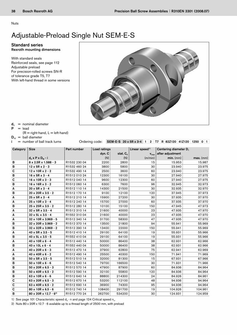
SEM-E-S 20 x 5R x 3-4 1 2 T7 R 82Z120 41Z120 1250 0 1
Precision Ball Screw Assemblies R310EN 3301 (2008.07)
d0 = nominal diameterP = lead (R = right-hand, L = left-hand)DW = ball diameter i = number of ball track turns Ordering code:
Category Size Part number Load ratings Linear speed1)
vmax
(m/min)
Centering diameter D1 after adjustmentdyn. C stat. C0
d0 x P x DW - i (N) (N) min. (mm) max. (mm)B 8 x 2.5R x 1.588 - 3 R1532 230 04 2200 2800 15 15.953 15.987B 12 x 5R x 2 - 3 R1532 460 24 3800 5800 30 23.940 23.975C 12 x 10R x 2 - 2 R1532 490 14 2500 3600 60 23.940 23.975B 16 x 5R x 3 - 4 R1512 010 24 12300 16100 30 27.940 27.975C 16 x 10R x 3 - 3 R1512 040 14 9600 12300 60 27.940 27.975B 16 x 16R x 3 - 2 R1512 060 14 6300 7600 96 32.945 32.973A 20 x 5R x 3 - 4 R1512 110 14 14300 21500 30 32.935 32.970B 20 x 20R x 3.5 - 2 R1512 170 14 9100 12100 120 37.945 37.973A 25 x 5R x 3 - 4 R1512 210 14 15900 27200 30 37.935 37.970A 25 x 10R x 3 - 4 R1512 240 14 15700 27000 60 37.935 37.970B 25 x 25R x 3.5 - 2 R1512 280 14 10100 15100 150 47.945 47.973A 32 x 5R x 3.5 - 4 R1512 310 14 21600 40000 23 47.935 47.970A 32 x 5L x 3.5 - 4 R1552 310 04 21600 40000 23 47.935 47.970A 32 x 10R x 3.969 - 5 R1512 340 14 31700 58300 47 47.935 47.970B 32 x 20R x 3.969 - 2 R1512 370 14 13500 21800 94 55.941 55.969B 32 x 32R x 3.969 - 2 R1512 390 14 13400 22000 150 55.941 55.969A 40 x 5R x 3.5 - 5 R1512 410 14 29100 64100 19 55.931 55.966B 40 x 5L x 3.5 - 5 R1552 410 04 29100 64100 19 55.931 55.966A 40 x 10R x 6 - 4 R1512 440 14 50000 86400 38 62.931 62.966B 40 x 10L x 6 - 4 R1552 440 04 50000 86400 38 62.931 62.966A 40 x 20R x 6 - 3 R1512 470 14 37900 62800 75 62.941 62.969A 40 x 40R x 6 - 2 R1512 490 14 25500 40300 150 71.941 71.969B 50 x 5R x 3.5 - 5 R1512 510 14 32000 81300 15 67.931 67.966B 50 x 10R x 6 - 6 R1512 540 14 79700 166500 30 71.931 71.966B 50 x 20R x 6.5 - 3 R1512 570 14 47900 87900 60 84.936 84.964B 50 x 40R x 6.5 - 2 R1512 590 14 32100 55800 120 84.936 84.964B 63 x 10R x 6 - 6 R1512 640 14 88800 214300 24 84.926 84.961C 63 x 20R x 6.5 - 3 R1512 670 14 53200 112100 48 94.936 94.964C 63 x 40R x 6.5 - 2 R1512 690 14 36900 74300 95 94.936 94.964C 80 x 10R x 6.5 - 6 R1512 740 14 108400 291700 19 104.926 104.961B 80 x 20R x 12.7 - 62) R1512 770 24 262700 534200 30 124.931 124.959
See page 101 Characteristic speed d0 · n and page 124 Critical speed ncr
Nuts 80 x 20R x 12.7 - 6 available up to a thread length of 2500 mm, with preload1)2)
Rexroth mounting dimensions
With standard sealsReinforced seals, see page 112Adjustable preloadFor precision-rolled screws SN-R of tolerance grade T5, T7 With left-hand thread in some versions
Adjustable-Preload Single Nut SEM-E-SStandard series
Nuts
39Bosch Rexroth AG
L 3
L
L 10
L 4
60°
D 7
S 60°
D 7
S
D 1
D 1 +
0,7
D 5
D 1 –0
,05
–0,1
L 5
L 3 L 4
D 5
D 1
ø6
D 7 3, 4
60°
D 6
S
9
D w
d 0
d 1
d 2
D 6 D 6
ϕ ϕ
BB7 BB7
BB7
Precision Ball Screw AssembliesR310EN 3301 (2008.07)
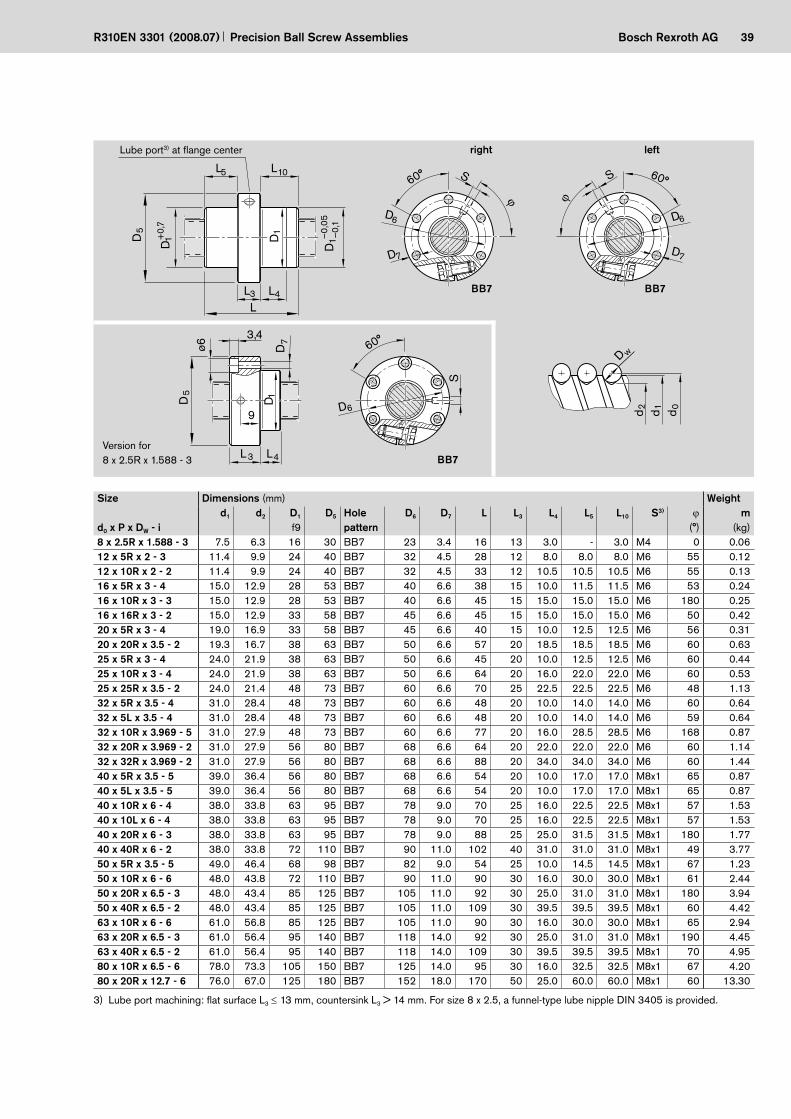
Size Dimensions (mm) Weight
d0 x P x DW - id1 d2 D1
f9D5 Hole
patternD6 D7 L L3 L4 L5 L10 S3) ϕ
(°)m
(kg)8 x 2.5R x 1.588 - 3 7.5 6.3 16 30 BB7 23 3.4 16 13 3.0 - 3.0 M4 0 0.0612 x 5R x 2 - 3 11.4 9.9 24 40 BB7 32 4.5 28 12 8.0 8.0 8.0 M6 55 0.1212 x 10R x 2 - 2 11.4 9.9 24 40 BB7 32 4.5 33 12 10.5 10.5 10.5 M6 55 0.1316 x 5R x 3 - 4 15.0 12.9 28 53 BB7 40 6.6 38 15 10.0 11.5 11.5 M6 53 0.2416 x 10R x 3 - 3 15.0 12.9 28 53 BB7 40 6.6 45 15 15.0 15.0 15.0 M6 180 0.2516 x 16R x 3 - 2 15.0 12.9 33 58 BB7 45 6.6 45 15 15.0 15.0 15.0 M6 50 0.4220 x 5R x 3 - 4 19.0 16.9 33 58 BB7 45 6.6 40 15 10.0 12.5 12.5 M6 56 0.3120 x 20R x 3.5 - 2 19.3 16.7 38 63 BB7 50 6.6 57 20 18.5 18.5 18.5 M6 60 0.6325 x 5R x 3 - 4 24.0 21.9 38 63 BB7 50 6.6 45 20 10.0 12.5 12.5 M6 60 0.4425 x 10R x 3 - 4 24.0 21.9 38 63 BB7 50 6.6 64 20 16.0 22.0 22.0 M6 60 0.5325 x 25R x 3.5 - 2 24.0 21.4 48 73 BB7 60 6.6 70 25 22.5 22.5 22.5 M6 48 1.1332 x 5R x 3.5 - 4 31.0 28.4 48 73 BB7 60 6.6 48 20 10.0 14.0 14.0 M6 60 0.6432 x 5L x 3.5 - 4 31.0 28.4 48 73 BB7 60 6.6 48 20 10.0 14.0 14.0 M6 59 0.6432 x 10R x 3.969 - 5 31.0 27.9 48 73 BB7 60 6.6 77 20 16.0 28.5 28.5 M6 168 0.8732 x 20R x 3.969 - 2 31.0 27.9 56 80 BB7 68 6.6 64 20 22.0 22.0 22.0 M6 60 1.1432 x 32R x 3.969 - 2 31.0 27.9 56 80 BB7 68 6.6 88 20 34.0 34.0 34.0 M6 60 1.4440 x 5R x 3.5 - 5 39.0 36.4 56 80 BB7 68 6.6 54 20 10.0 17.0 17.0 M8x1 65 0.8740 x 5L x 3.5 - 5 39.0 36.4 56 80 BB7 68 6.6 54 20 10.0 17.0 17.0 M8x1 65 0.8740 x 10R x 6 - 4 38.0 33.8 63 95 BB7 78 9.0 70 25 16.0 22.5 22.5 M8x1 57 1.5340 x 10L x 6 - 4 38.0 33.8 63 95 BB7 78 9.0 70 25 16.0 22.5 22.5 M8x1 57 1.5340 x 20R x 6 - 3 38.0 33.8 63 95 BB7 78 9.0 88 25 25.0 31.5 31.5 M8x1 180 1.7740 x 40R x 6 - 2 38.0 33.8 72 110 BB7 90 11.0 102 40 31.0 31.0 31.0 M8x1 49 3.7750 x 5R x 3.5 - 5 49.0 46.4 68 98 BB7 82 9.0 54 25 10.0 14.5 14.5 M8x1 67 1.2350 x 10R x 6 - 6 48.0 43.8 72 110 BB7 90 11.0 90 30 16.0 30.0 30.0 M8x1 61 2.4450 x 20R x 6.5 - 3 48.0 43.4 85 125 BB7 105 11.0 92 30 25.0 31.0 31.0 M8x1 180 3.9450 x 40R x 6.5 - 2 48.0 43.4 85 125 BB7 105 11.0 109 30 39.5 39.5 39.5 M8x1 60 4.4263 x 10R x 6 - 6 61.0 56.8 85 125 BB7 105 11.0 90 30 16.0 30.0 30.0 M8x1 65 2.9463 x 20R x 6.5 - 3 61.0 56.4 95 140 BB7 118 14.0 92 30 25.0 31.0 31.0 M8x1 190 4.4563 x 40R x 6.5 - 2 61.0 56.4 95 140 BB7 118 14.0 109 30 39.5 39.5 39.5 M8x1 70 4.9580 x 10R x 6.5 - 6 78.0 73.3 105 150 BB7 125 14.0 95 30 16.0 32.5 32.5 M8x1 67 4.2080 x 20R x 12.7 - 6 76.0 67.0 125 180 BB7 152 18.0 170 50 25.0 60.0 60.0 M8x1 60 13.30
Version for 8 x 2.5R x 1.588 - 3
right leftLube port3) at flange center
Lube port machining: flat surface L3 ≤ 13 mm, countersink L3 > 14 mm. For size 8 x 2.5, a funnel-type lube nipple DIN 3405 is provided.3)

40 Bosch Rexroth AG
ZEM-E-S 20 x 5R x 3-5 1 2 T7 R 82Z120 41Z120 1250 0 1
Precision Ball Screw Assemblies R310EN 3301 (2008.07)
d0 = nominal diameterP = lead (R = right-hand, L = left-hand)DW = ball diameter i = number of ball track turns
Ordering code:
See page 101 Characteristic speed d0 · n and page 124 Critical speed ncr
Special nuts for Rexroth modules and drive units
1)
2)
Cylindrical Single Nut ZEM-E-S
Rexroth mounting dimensions
With standard sealsReinforced seals, see page 112With backlash, reduced backlash, preload 2%; 3%; 5%For precision-rolled screws SN-R of tolerance grade T5, T7, T9 With left-hand thread in some versions
Standard series
Nuts
Category Size Part number Load ratings Linear speed1)
d0 x P x Dw - i dyn. C stat. C0 vmax
(N) (N) (m/min)A 8 x 2.5R x 1.588 - 3 R1532 230 02 2200 2800 15B2) 12 x 2R x 1.2 - 4 R1532 422 01 2240 4160 12A 12 x 5R x 2 - 3 R1532 460 32 3800 5800 30B2) 12 x 5R x 2 - 3 R1532 462 25 3800 5800 30B 12 x 10R x 2 - 2 R1532 490 22 2500 3600 60B2) 12 x 10R x 2 - 2 R1532 492 00 2500 3600 60A 16 x 5R x 3 - 4 R1512 010 22 12300 16100 30C 16 x 5L x 3 - 4 R1552 010 02 12300 16100 30B2) 16 x 5R x 3 - 4 R1512 012 67 12300 16100 30A 16 x 10R x 3 - 3 R1512 040 12 9600 12300 60B2) 16 x 10R x 3 - 3 R1512 042 08 9600 12300 60 B2) 16 x 10R x 3 - 3 R1512 042 09 9600 12300 60A 16 x 16R x 3 - 2 R1512 060 12 6300 7600 96B2) 16 x 16R x 3 - 2 R1512 062 10 6300 7600 96B2) 16 x 16R x 3 - 3 R1512 062 11 9600 12300 96A 20 x 5R x 3 - 5 R1512 110 12 17500 27300 30B2) 20 x 5R x 3 - 4 R1512 112 43 14300 21500 30A 20 x 20R x 3.5 - 2 R1512 170 12 9100 12100 120B2) 20 x 20R x 3.5 - 3 R1512 172 07 13300 18800 120A 25 x 5R x 3 - 4 R1512 210 12 15900 27200 30A 25 x 10R x 3 - 4 R1512 240 12 15700 27000 60B 25 x 25R x 3.5 - 2 R1512 280 12 10100 15100 150B 25 x 25R x 3.5 - 3 R1512 280 52 14700 23300 150B 32 x 5R x 3.5 - 4 R1512 310 12 21600 40000 23A 32 x 10R x 3.969 - 5 R1512 340 12 31700 58300 47C 32 x 20R x 3.969 - 2 R1512 370 12 13500 21800 94B 32 x 20R x 3.969 - 3 R1512 370 52 19700 33700 94B 32 x 32R x 3.969 - 2 R1512 390 12 13400 22000 150B 32 x 32R x 3.969 - 3 R1512 390 52 19500 34000 150C 40 x 5R x 3.5 - 5 R1512 410 12 29100 64100 19B2) 40 x 5R x 3.5 - 5 R1512 412 21 29100 64100 19B 40 x 10R x 6 - 4 R1512 440 12 50000 86400 38B 40 x 20R x 6 - 3 R1512 470 12 37900 62800 75B 40 x 40R x 6 - 2 R1512 490 12 25500 40300 150B 40 x 40R x 6 - 3 R1512 490 52 37000 62300 150B 50 x 5R x 3.5 - 5 R1512 510 12 32000 81300 15C 50 x 10R x 6 - 6 R1512 540 12 79700 166500 30C 50 x 20R x 6.5 - 3 R1512 570 12 47900 87900 60C 63 x 10R x 6 - 6 R1512 640 12 88800 214300 24

41Bosch Rexroth AG
T 1
L 7
L 6 L 11
L
D 1
A
0,2
B
D w
d 0
d 1
d 2
A
D 4
Precision Ball Screw AssembliesR310EN 3301 (2008.07)
Size Dimensions (mm) Weight
d0 x P x DW - id1 d2 D1
g6D4 L
±0.1L6 L7 L11
+0.2B
P9T1
+0.1m
(kg)8 x 2.5R x 1.588 - 3 7.5 6.3 16 2 16 5.0 3.5 6 3 1.8 0.0212 x 2R x 1.2 - 4 11.7 10.8 21 2 19 5.5 3.5 8 3 1.8 0.0312 x 5R x 2 - 3 11.4 9.9 24 2 28 8.0 3.5 12 5 3.0 0.0612 x 5R x 2 - 3 11.4 9.9 21 2 28 8.0 3.5 12 3 1.8 0.0412 x 10R x 2 - 2 11.4 9.9 24 2 33 10.5 3.5 12 5 3.0 0.0712 x 10R x 2 - 2 11.4 9.9 21 2 33 10.5 3.5 12 3 1.8 0.0516 x 5R x 3 - 4 15.0 12.9 28 4 35 14.5 9.5 12 5 3.0 0.0916 x 5L x 3 - 4 15.0 12.9 28 4 35 14.5 9.5 12 5 3.0 0.0916 x 5R x 3 - 4 15.0 12.9 33 4 45 14.5 9.5 16 5 3.0 0.1716 x 10R x 3 - 3 15.0 12.9 28 4 45 14.5 9.5 16 5 3.0 0.1216 x 10R x 3 - 3 15.0 12.9 38 4 54 19.0 9.5 16 5 3.0 0.3516 x 10R x 3 - 3 15.0 12.9 33 4 45 14.5 9.5 16 5 3.0 0.2016 x 16R x 3 - 2 15.0 12.9 33 4 45 14.5 9.5 16 5 3.0 0.2016 x 16R x 3 - 2 15.0 12.9 28 4 45 14.5 9.5 16 5 3.0 0.1216 x 16R x 3 - 3 15.0 12.9 38 4 61 22.5 9.5 16 5 3.0 0.4220 x 5R x 3 - 5 19.0 16.9 33 4 45 14.5 9.5 16 5 3.0 0.1620 x 5R x 3 - 4 19.0 16.9 38 4 40 21.0 9.5 12 5 3.0 0.2120 x 20R x 3.5 - 2 19.3 16.7 38 4 64 22.0 9.5 20 5 3.0 0.3420 x 20R x 3.5 - 3 19.3 16.7 38 4 77 28.5 9.5 20 5 3.0 0.4425 x 5R x 3 - 4 24.0 21.9 38 4 45 14.5 9.5 16 5 3.0 0.1925 x 10R x 3 - 4 24.0 21.9 38 4 64 22.0 9.5 20 5 3.0 0.2825 x 25R x 3.5 - 2 24.0 21.4 48 4 80 30.0 10.5 20 5 3.0 0.7325 x 25R x 3.5 - 3 24.0 21.4 40 4 95 37.5 10.5 20 5 3.0 0.5032 x 5R x 3.5 - 4 31.0 28.4 48 4 48 14.0 9.5 20 5 3.0 0.3232 x 10R x 3.969 - 5 31.0 27.9 48 4 77 28.5 9.5 20 5 3.0 0.5032 x 20R x 3.969 - 2 31.0 27.9 56 4 64 22.0 9.5 20 5 3.0 0.7432 x 20R x 3.969 - 3 31.0 27.9 50 4 84 32.0 9.5 20 5 3.0 0.6632 x 32R x 3.969 - 2 31.0 27.9 56 4 88 34.0 9.5 20 5 3.0 1.0332 x 32R x 3.969 - 3 31.0 27.9 50 4 120 50.0 9.5 20 5 3.0 0.9740 x 5R x 3.5 - 5 39.0 36.4 56 4 54 17.0 9.5 20 5 3.0 0.4440 x 5R x 3.5 - 5 39.0 36.4 63 4 70 25.0 14.0 20 5 3.0 0.8240 x 10R x 6 - 4 38.0 33.8 63 4 70 25.0 14.0 20 5 3.0 0.8840 x 20R x 6 - 3 38.0 33.8 63 4 88 34.0 14.0 20 5 3.0 1.1340 x 40R x 6 - 2 38.0 33.8 72 4 113 46.5 14.0 20 5 3.0 2.2340 x 40R x 6 - 3 38.0 33.8 63 4 142 61.0 14.0 20 5 3.0 1.8550 x 5R x 3.5 - 5 49.0 46.4 68 4 54 17.0 9.5 20 5 3.0 0.6250 x 10R x 6 - 6 48.0 43.8 72 5 90 35.0 14.0 20 5 3.0 1.3450 x 20R x 6.5 - 3 48.0 43.4 85 5 92 30.0 14.0 32 6 3.5 2.3963 x 10R x 6 - 6 61.0 56.8 85 5 90 29.0 14.0 32 6 3.5 1.59
Lube port

42 Bosch Rexroth AG
FED-E-B 40 x 20R x 6 - 8 x 2 1 6 T5 R 13Z400 41K300 0 1
Precision Ball Screw Assemblies R310EN 3301 (2008.07)
d0 = nominal diameterP = lead (R = right-hand, L = left-hand)DW = ball diameteri = a x ba = load-carrying turnsb = number of load-carrying threads
on the screw
Ordering code:
2-start Single Nut with Flange FED-E-B
Nuts
Standard seriesMounting dimensions similar toDIN 69 051, Part 5Flange type B
2-start nuts to distinctly increase the dynamic and static load ratingMounting dimensions correspond to those of the Rexroth standard series
With standard sealsWith backlash, reduced backlash, preload 3%For precision-rolled screws SN-R of tolerance grade T5, T7
The load-bearing capability of the rolling contact is greater than the mechanical strength of the nut body, therefore, maximum static load data has been included.In preparation
1)
2)
Size Part number Load ratings Max. static Linear speeddyn. C stat. C0 load1) vmax
d0 x P x DW - i x b (kN) (kN) (kN) (m/min)40 x 20 R x 6 - 8 x 2 R1512 470 32 76.4 171.1 87 7540 x 40 R x 6 - 6 x 2 R1512 490 32 57.2 124.5 83 15050 x 20 R x 6.5 - 8 x 2 R1512 570 32 93.2 228.0 120 6050 x 25 R x 6.5 - 6 x 2 R1512 580 322) 74.1 175.1 117 7550 x 40 R x 6.5 - 6 x 2 R1512 590 32 71.4 171.5 119 12063 x 20 R x 6.5 - 8 x 2 R1512 670 32 104.6 292.0 142 4863 x 40 R x 6.5 - 6 x 2 R1512 690 32 80.0 217.0 148 95
43Bosch Rexroth AG
D 1
D 1
L 5 L 3 L 4
L 10
5 L
D 6 D
7 D
14
L 30°
90°
–0,0
5–0
,1
30°S D w
d 0
d 1
d 2
Precision Ball Screw AssembliesR310EN 3301 (2008.07)
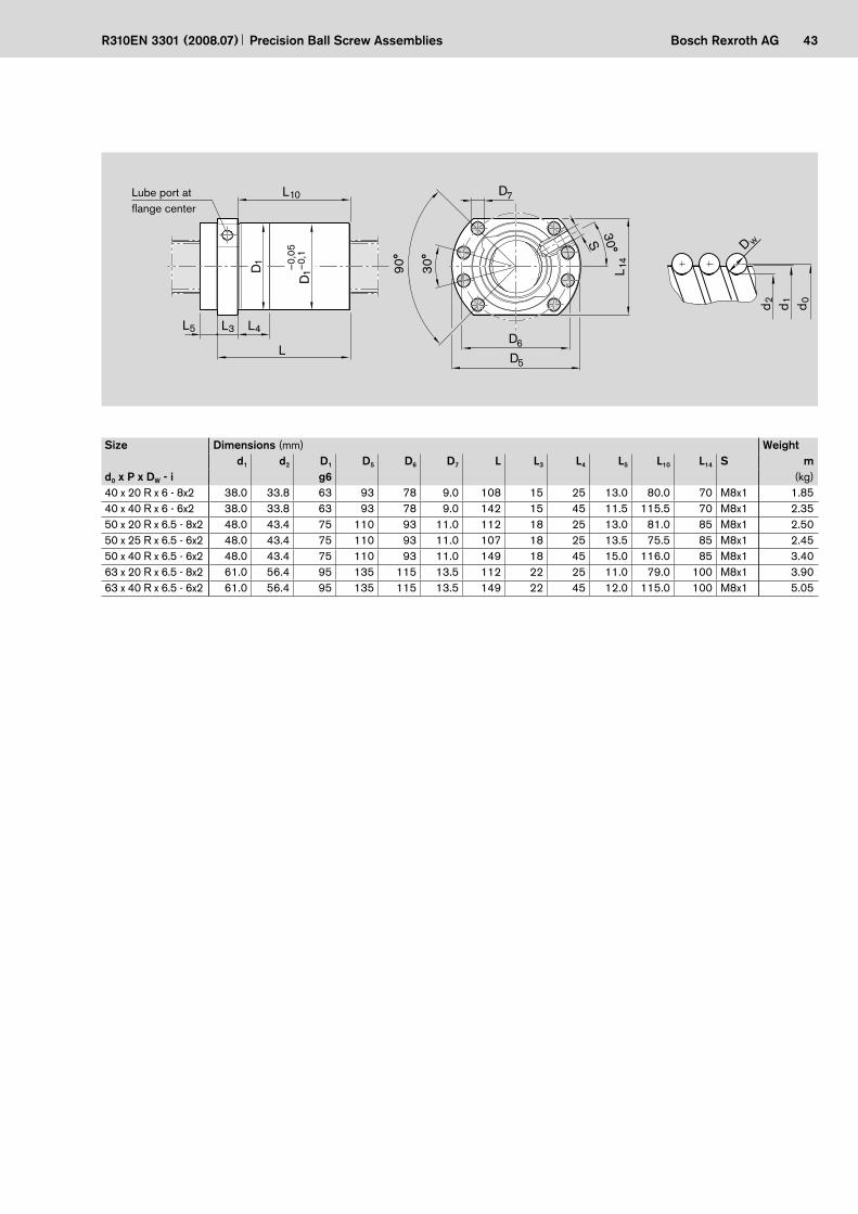
Size Dimensions (mm) Weightd1 d2 D1 D5 D6 D7 L L3 L4 L5 L10 L14 S m
d0 x P x DW - i g6 (kg)40 x 20 R x 6 - 8x2 38.0 33.8 63 93 78 9.0 108 15 25 13.0 80.0 70 M8x1 1.8540 x 40 R x 6 - 6x2 38.0 33.8 63 93 78 9.0 142 15 45 11.5 115.5 70 M8x1 2.3550 x 20 R x 6.5 - 8x2 48.0 43.4 75 110 93 11.0 112 18 25 13.0 81.0 85 M8x1 2.5050 x 25 R x 6.5 - 6x2 48.0 43.4 75 110 93 11.0 107 18 25 13.5 75.5 85 M8x1 2.4550 x 40 R x 6.5 - 6x2 48.0 43.4 75 110 93 11.0 149 18 45 15.0 116.0 85 M8x1 3.4063 x 20 R x 6.5 - 8x2 61.0 56.4 95 135 115 13.5 112 22 25 11.0 79.0 100 M8x1 3.9063 x 40 R x 6.5 - 6x2 61.0 56.4 95 135 115 13.5 149 22 45 12.0 115.0 100 M8x1 5.05
Lube port at flange center

44 Bosch Rexroth AG
FDM-E-C 20 x 5R x 3-4 1 2 T7 R 82Z120 41Z120 1250 0 1
Precision Ball Screw Assemblies R310EN 3301 (2008.07)
d0 = nominal diameterP = lead (R = right-hand, L = left-hand)DW = ball diameter i = number of ball track turns
Double Nut with Flange FDM-E-C
Mounting dimensions per DIN 69 051, Part 5Flange type C
With standard sealsReinforced seals, see page 112With preload 7% or 10% For precision-rolled screws SN-R of tolerance grade T5, T7
Standard series
Ordering code:
Category Size Part number Load ratings Linear speed1)
d0 x P x DW - idyn. C
(N)stat. C0
(N)vmax
(m/min)C 16 x 5R x 3 - 4 R1502 010 55 12300 16100 30C 20 x 5R x 3 - 4 R1502 110 75 14300 21500 30C 25 x 5R x 3 - 4 R1502 210 75 15900 27200 30C 25 x 10R x 3 - 4 R1502 240 75 15700 27000 60C 32 x 5R x 3.5 - 4 R1502 310 75 21600 40000 23C 32 x 10R x 3.969 - 5 R1502 340 76 31700 58300 47C 40 x 5R x 3.5 - 5 R1502 410 76 29100 64100 19C 40 x 10R x 6 - 4 R1502 440 75 50000 86400 38C 40 x 10R x 6 - 6 R1502 440 76 72100 132200 38C 40 x 20R x 6 - 3 R1502 470 75 37900 62800 75C 50 x 5R x 3.5 - 5 R1502 510 76 32000 81300 15C 50 x 10R x 6 - 4 R1502 540 75 55400 109000 30C 50 x 10R x 6 - 6 R1502 540 76 79700 166500 30C 50 x 20R x 6.5 - 5 R1502 570 76 75700 149700 60C 63 x 10R x 6 - 4 R1502 640 75 61800 140500 24C 63 x 10R x 6 - 6 R1502 640 76 88800 214300 24C 63 x 20R x 6.5 - 5 R1502 670 76 83900 190300 48C 80 x 10R x 6.5 - 6 R1502 740 76 108400 291700 19C 80 x 20R x 12.7 - 62) R1502 770 46 262700 534200 30
See page 101 Characteristic speed d0 · n and page 124 Critical speed ncr
Nuts 80 x 20R x 12.7 - 6 available up to a thread length of 2500 mm, with preload1)2)
Nuts

45Bosch Rexroth AG
L
L 4L3
90°
22,5°
90°
30°
30°
D7
D7
S
D6
S
D6
D5 D1
L 9L 9
L10
D1–0
,04
–0,2
Dw
d 0d 1d 2
d0 ≤ 32
d0 ≥ 40
BB2
BB1
Precision Ball Screw AssembliesR310EN 3301 (2008.07)
Size Dimensions (mm) Weight
d0 x P x DW - id1 d2 D1
g6D5 Hole
patternD6 D7 L L3 L4 L9 L10 S3) m
(kg)16 x 5R x 3 - 4 15.0 12.9 28 48 BB2 38 5.5 72 12 10 44.0 60 M6 0.2920 x 5R x 3 - 4 19.0 16.9 36 58 BB2 47 6.6 82 12 10 51.0 70 M6 0.5325 x 5R x 3 - 4 24.0 21.9 40 62 BB2 51 6.6 82 12 10 55.0 70 M6 0.5725 x 10R x 3 - 4 24.0 21.9 40 62 BB2 51 6.6 120 12 16 55.0 108 M6 0.7732 x 5R x 3.5 - 4 31.0 28.4 50 80 BB2 65 9.0 88 13 10 71.0 75 M6 0.9632 x 10R x 3.969 - 5 31.0 27.9 50 80 BB2 65 9.0 146 13 16 71.0 133 M6 1.3440 x 5R x 3.5 - 5 39.0 36.4 63 93 BB1 78 9.0 100 15 10 81.5 85 M8x1 1.6840 x 10R x 6 - 4 38.0 33.8 63 93 BB1 78 9.0 140 15 16 81.5 125 M8x1 2.1540 x 10R x 6 - 6 38.0 33.8 63 93 BB1 78 9.0 180 15 16 81.5 165 M8x1 2.7340 x 20R x 6 - 3 38.0 33.8 63 93 BB1 78 9.0 175 15 25 81.5 160 M8x1 2.5650 x 5R x 3.5 - 5 49.0 46.4 75 110 BB1 93 11.0 100 15 10 97.5 85 M8x1 2.2550 x 10R x 6 - 4 48.0 43.8 75 110 BB1 93 11.0 140 18 16 97.5 122 M8x1 2.9750 x 10R x 6 - 6 48.0 43.8 75 110 BB1 93 11.0 180 18 16 97.5 162 M8x1 3.7350 x 20R x 6.5 - 5 48.0 43.4 75 110 BB1 93 11.0 255 18 25 97.5 237 M8x1 4.9363 x 10R x 6 - 4 61.0 56.8 90 125 BB1 108 11.0 140 22 16 110.0 118 M8x1 4.0063 x 10R x 6 - 6 61.0 56.8 90 125 BB1 108 11.0 180 22 16 110.0 158 M8x1 4.4563 x 20R x 6.5 - 5 61.0 56.4 95 135 BB1 115 13.5 255 22 25 117.5 233 M8x1 8.2180 x 10R x 6.5 - 6 78.0 73.3 105 145 BB1 125 13.5 190 22 16 127.5 168 M8x1 5.9380 x 20R x 12.7 - 6 76.0 67.0 125 165 BB1 145 13.5 340 25 25 147.5 315 M8x1 19.40
Lube port3) at flange center
Lube port machining: flat surface L3 ≤ 13 mm, countersink L3 > 14 mm3)

46 Bosch Rexroth AG
FDM-E-S 20 x 5R x 3-4 1 2 T7 R 82Z120 41Z120 1250 0 1
Precision Ball Screw Assemblies R310EN 3301 (2008.07)
Nuts
d0 = nominal diameterP = lead (R = right-hand, L = left-hand)DW = ball diameter i = number of ball track turns
Ordering code:
Category Size Part number Load ratings Linear speed1)
d0 x P x DW - idyn. C
(N)stat. C0
(N)vmax
(m/min)C 16 x 5R x 3 - 4 R1502 010 23 12300 16100 30C 20 x 5R x 3 - 4 R1502 110 33 14300 21500 30C 25 x 5R x 3 - 4 R1502 210 33 15900 27200 30C 25 x 10R x 3 - 4 R1502 240 33 15700 27000 60C 32 x 5R x 3.5 - 4 R1502 310 33 21600 40000 23C 32 x 10R x 3.969 - 5 R1502 340 33 31700 58300 47C 40 x 5R x 3.5 - 5 R1502 410 33 29100 64100 19C 40 x 10R x 6 - 4 R1502 440 33 50000 86400 38C 40 x 10R x 6 - 6 R1502 440 34 72100 132200 38C 40 x 20R x 6 - 3 R1502 470 33 37900 62800 75C 50 x 5R x 3.5 - 5 R1502 510 33 32000 81300 15C 50 x 10R x 6 - 4 R1502 540 33 55400 109000 30C 50 x 10R x 6 - 6 R1502 540 34 79700 166500 30C 50 x 20R x 6.5 - 5 R1502 570 34 75700 149700 60C 63 x 10R x 6 - 4 R1502 640 33 61800 140500 24C 63 x 10R x 6 - 6 R1502 640 34 88800 214300 24C 63 x 20R x 6.5 - 5 R1502 670 34 83900 190300 48C 80 x 10R x 6.5 - 6 R1502 740 34 108400 291700 19C 80 x 20R x 12.7 - 62) R1502 770 04 262700 534200 30
See page 101 Characteristic speed d0 · n and page 124 Critical speed ncr
Nuts 80 x 20R x 12.7 - 6 available up to a thread length of 2500 mm, with preload1)2)
Double Nut with Flange FDM-E-S
Rexroth mounting dimensions
With standard sealsReinforced seals, see page 112With preload 7% or 10%For precision-rolled screws SN-R of tolerance grade T5, T7
Standard series

47Bosch Rexroth AG
L
L 4L3
6x6
0°
30°
D7
S
4x90°
45
°
S
8x4
5°
22
,5°
S
D7
D5 D1
D 1–0
,04
–0,2
L10
Dw
d 0d 1d 2
D6
D7
D6
D6
Precision Ball Screw AssembliesR310EN 3301 (2008.07)
Size Dimensions (mm) Weight
d0 x P x DW - id1 d2 D1
g6D5 Hole
patternD6 D7 L L3 L4 L10 S3) m
(kg)16 x 5R x 3 - 4 15.0 12.9 28 53 BB3 40 6.6 72 12 10 60 M6 0.3320 x 5R x 3 - 4 19.0 16.9 33 58 BB4 45 6.6 82 12 10 70 M6 0.4525 x 5R x 3 - 4 24.0 21.9 38 63 BB4 50 6.6 82 12 10 70 M6 0.5325 x 10R x 3 - 4 24.0 21.9 38 63 BB4 50 6.6 120 12 16 108 M6 0.7032 x 5R x 3.5 - 4 31.0 28.4 48 73 BB4 60 6.6 88 13 10 75 M6 0.8432 x 10R x 3.969 - 5 31.0 27.9 48 73 BB4 60 6.6 146 13 16 133 M6 1.2240 x 5R x 3.5 - 5 39.0 36.4 56 80 BB4 68 6.6 100 15 10 85 M8x1 1.1340 x 10R x 6 - 4 38.0 33.8 63 95 BB4 78 9.0 140 15 16 125 M8x1 2.2540 x 10R x 6 - 6 38.0 33.8 63 95 BB4 78 9.0 180 15 16 165 M8x1 2.8340 x 20R x 6 - 3 38.0 33.8 63 95 BB4 78 9.0 175 15 25 160 M8x1 2.6650 x 5R x 3.5 - 5 49.0 46.4 68 98 BB4 82 9.0 100 15 10 85 M8x1 1.6050 x 10R x 6 - 4 48.0 43.8 72 110 BB4 90 11.0 140 18 16 122 M8x1 2.7450 x 10R x 6 - 6 48.0 43.8 72 110 BB4 90 11.0 180 18 16 162 M8x1 3.3950 x 20R x 6.5 - 5 48.0 43.4 85 125 BB4 105 11.0 255 22 25 233 M8x1 6.7163 x 10R x 6 - 4 61.0 56.8 85 125 BB4 105 11.0 140 22 16 118 M8x1 3.5363 x 10R x 6 - 6 61.0 56.8 85 125 BB4 105 11.0 180 22 16 158 M8x1 4.3263 x 20R x 6.5 - 5 61.0 56.4 95 140 BB4 118 14.0 255 22 25 233 M8x1 8.6580 x 10R x 6.5 - 6 78.0 73.3 105 150 BB4 125 14.0 190 22 16 168 M8x1 6.3580 x 20R x 12.7 - 6 76.0 67.0 125 180 BB5 152 18.0 340 25 25 315 M8x1 20.20
BB4BB3
BB6BB5
Lube port3) at flange center
Lube port machining: flat surface L3 ≤ 13 mm, countersink L3 > 14 mm3)
48 Bosch Rexroth AG Precision Ball Screw Assemblies R310EN 3301 (2008.07)
Nut Housings
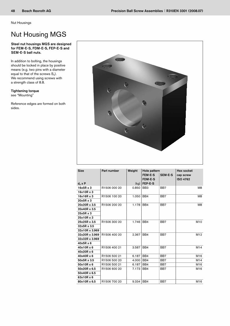
In addition to bolting, the housings should be locked in place by positive means (e.g. two pins with a diameter equal to that of the screws S2).We recommend using screws with a strength class of 8.8.
Tightening torquesee “Mounting”
Reference edges are formed on both sides.
Nut Housing MGSSteel nut housings MGS are designed for FEM-E-S, FDM-E-S, FEP-E-S and SEM-E-S ball nuts.
Size
d0 x P
Part number Weight
(kg)
Hole pattern Hex socket cap screwISO 4762
FEM-E-SFDM-E-SFEP-E-S
SEM-E-S
16x5R x 3 R1506 000 20 0.850 BB3 BB7 M816x10R x 316x16R x 3 R1506 100 20 1.050 BB4 BB7 M820x5R x 320x20R x 3.5 R1506 200 20 1.178 BB4 BB7 M820x40R x 3.525x5R x 325x10R x 325x25R x 3.5 R1506 300 20 1.746 BB4 BB7 M1032x5R x 3.532x10R x 3.96932x20R x 3.969 R1506 400 20 2.367 BB4 BB7 M1232x32R x 3.96940x5R x 640x10R x 6 R1506 400 21 3.587 BB4 BB7 M1440x20R x 640x40R x 6 R1506 500 21 6.187 BB4 BB7 M1650x5R x 3.5 R1506 500 20 4.000 BB4 BB7 M1450x10R x 6 R1506 500 21 6.187 BB4 BB7 M1650x20R x 6.5 R1506 600 20 7.173 BB4 BB7 M1650x40R x 6.563x10R x 680x10R x 6.5 R1506 700 20 9.334 BB4 BB7 M16

49Bosch Rexroth AG
L
T 1
2
S1
S T2
S2
E2 N
A
4 x
90°
6x60
°H
1
E1
B
2 x B
H
H
D6
D 1
30°
BB4/BB7 BB3 / BB7
Precision Ball Screw AssembliesR310EN 3301 (2008.07)
Size
d0 x P
Dimensions (mm)
D1
H7D6 A B
±0.01H
±0.01H1 H2 E1 E2 N S S1 T1 S2 T2 Clamping
length L16x5R x 3 28 40 40 35.0 28 55 10 52±0.1 20±0.1 10 8.4 M10 15 M6 10 44.016x10R x 316x16R x 3 33 45 40 37.5 32 62 10 56±0.1 20±0.1 10 8.4 M10 15 M6 10 51.020x5R x 320x20R x 3.5 38 50 40 42.5 34 65 10 63±0.1 20±0.1 10 8.4 M10 15 M6 10 54.020x40R x 3.525x5R x 325x10R x 325x25R x 3.5 48 60 50 47.5 38 75 10 72±0.1 26±0.1 12 10.5 M12 15 M6 10 61.032x5R x 3.532x10R x 3.96932x20R x 3.969 56 68 60 52.5 42 82 12 82±0.1 30±0.1 15 13.0 M16 20 M6 12 64.032x32R x 3.96940x5R x 640x10R x 6 63 78 65 60.0 50 98 12 93±0.1 35±0.1 15 15.0 M18 25 M8 14 79.540x20R x 640x40R x 6 72 90 80 70.0 58 113 12 108±0.15 46±0.15 17 17.0 M20 30 M10 18 92.050x5R x 3.5 68 82 65 65.0 52 101 12 100±0.15 35±0.15 15 15.0 M18 30 M8 14 82.550x10R x 6 72 90 80 70.0 58 113 12 108±0.15 46±0.15 17 17.0 M20 30 M10 18 92.050x20R x 6.5 85 105 80 75.0 65 128 15 121±0.15 46±0.15 17 17.0 M20 30 M10 18 107.050x40R x 6.563x10R x 680x10R x 6.5 105 125 80 85.0 78 153 15 140±0.20 46±0.15 17 17.0 M20 30 M12 20 132.0
for size 16x5/16x10

50 Bosch Rexroth AG Precision Ball Screw Assemblies R310EN 3301 (2008.07)
Nut Housings
Size Part number Weight Hole pattern Hex socket capscrew ISO 4762
d0 x P (kg)16x5 R1506 000 50 0.91 BB2 M816x1016x1620x5 R1506 100 50 1.18 BB2 M820x2025x5 R1506 200 50 1.33 BB2 M825x1025x2532x5 R1506 300 50 2.27 BB2 M1232x1032x2032x3240x5 R1506 400 50 3.61 BB1 M1440x1040x1240x1640x2040x4050x5 R1506 500 50 5.63 BB1 M1650x1050x1250x1650x2050x4063x10 R1506 600 50 6.72 BB1 M1663x20 R1506 600 51 7.67 BB1 M1663x4080x10 R1506 700 50 8.60 BB1 M1680x20 R1506 700 51 10.53 BB1 M16
In addition to bolting, the housings should be locked in place by positive means (e.g. two pins with a diameter equal to that of the screws S2).We recommend using screws with a strength class of 8.8.
Tightening torquesee “Mounting”
Reference edges are formed on both sides.
Steel nut housings MGD are designed for FEM-E-C, FDM-E-C and SEM-E-C ball nuts.
Nut Housing MGD

51Bosch Rexroth AG
90°
90°
30°
2 x BH
1
H2
H
B
E1N
T 1
S1
S T2
S2
E2
A
D 6
D 1
L
BB2 BB1
Precision Ball Screw AssembliesR310EN 3301 (2008.07)
Size
d0 x P
Dimensions (mm)D1
H7D6 A B
±0.01H
±0.01H1 H2 E1 E2 N S S1 T1 S2 T2 Clamping
length L16x5 28 38 50 35 24 48 10 50±0.1 20±0.1 20 8.4 M10 15 M5 10 37.016x1016x1620x5 36 47 55 37.5 28 56 10 55±0.1 23±0.1 22 8.4 M10 15 M6 11 45.020x2025x5 40 51 55 40 30 60 10 60±0.1 23±0.1 22 8.4 M10 15 M6 11 49.025x1025x2532x5 50 65 70 50 35 70 10 75±0.1 30±0.1 27 13.0 M16 20 M8 14 52.032x1032x2032x3240x5 63 78 80 60 42 84 12 90±0.1 35±0.1 31 15.0 M18 25 M8 17 65.540x1040x1240x1640x2040x4050x5 75 93 95 70 48 96 12 110±0.15 45±0.15 34 17.0 M20 30 M10 17 75.050x1050x1250x1650x2050x4063x10 90 108 100 75 55 110 15 120±0.2 46±0.15 37 17.0 M20 30 M10 20 89.063x20 95 115 100 80 58 116 15 130±0.2 46±0.15 37 17.0 M20 30 M12 20 95.063x4080x10 105 125 100 85 63 126 15 140±0.2 46±0.15 37 17.0 M20 30 M12 20 105.080x20 125 145 100 95 73 146 15 160±0.2 46±0.15 37 17.0 M20 30 M12 22 125.0

52 Bosch Rexroth AG Precision Ball Screw Assemblies R310EN 3301 (2008.07)
Nut Housings
Nut Housing MGA-Z
Size Part number Weight Hex socket cap screw for screwing from below
d0 x P (kg) ISO 476220 x 5 R1506 100 70 1.10 M820 x 2032 x 5 R1506 300 70 2.31 M1032 x 1032 x 2032 x 3240 x 5 R1506 400 70 4.323 M1440 x 1040 x 2040 x 40
We recommend using screws with a strength class of 8.8.
Tightening torquesee “Mounting”
Reference edges are formed on both sides.
Scope of supply: Includes set screws, spacer ring, ring nut, key
Aluminum nut housings MGA are designed for ZEM-E-S ball nuts.

53Bosch Rexroth AG
2 x B
BS1
E1L
T 1
ØD
1
AE2
H2
H
H1
S1
T2
T3
S
HA5
A
A
A - A
Precision Ball Screw AssembliesR310EN 3301 (2008.07)
Size Dimensions (mm)d0 x P A B
±0.01ØD1
H6E1 E2 H
±0.01H1 H2 HA5 S S1 T1 T2 T3 Clamping
length L20 x 5 100 37.5 38 55 60 44 75 8 15 8.6 M10 15 11 86 6320 x 2032 x 5 150 50.0 50 75 100 49 80 9 16 10.5 M12 18 15 131 6632 x 1032 x 2032 x 3240 x 5 180 60.0 63 90 120 59 105 10 18 14.5 M16 24 20 155 8640 x 1040 x 2040 x 40
Countersink for O-ring 7 x 1.5

54 Bosch Rexroth AG
SN 20 x 5R x 3 X X T7 R 00T200 00T200 1250 1 0
d 0
d 1
d 2
D w
Precision Ball Screw Assemblies R310EN 3301 (2008.07)
Precision-Rolled Screw SN-R
Screws
Please state length in the “Inquiry/Order Form”Ltot = overall length
Ordering code:
Ltot
The outer diameter d1 has been changed.1) In preparation2)
Size
d0 x P x DW
Part number Dimensions(mm)
Moment of inertia Maximum length (mm) WeightTolerancegrade T5
Tolerancegrade T7
Tolerancegrade T9
Js Standard On request (kg/m)d1 d2 (kgcm2/m)
6 x 1R x 0.8 R1531 105 00 R1531 107 00 R1531 109 00 6.0 5.3 0.02 On request 0.196 x 2R x 0.8 R1531 125 00 R1531 127 00 R1531 129 00 6.0 5.3 0.02 0.198 x 1R x 0.8 R1531 205 00 R1531 207 00 R1531 209 00 8.0 7.3 0.04 0.368 x 2R x 1.2 R1531 225 00 R1531 227 00 R1531 229 00 8.0 7.0 0.04 0.368 x 2.5R x 1.588 R1531 235 00 R1531 237 00 R1531 239 00 7.5 6.3 0.04 0.3012 x 2R x 1.2 R1531 425 00 R1531 427 00 R1531 429 00 11.7 10.8 0.13 1500 2500 0.7912 x 5R x 2 R1531 465 10 R1531 467 10 R1531 469 10 11.4 9.9 0.11 0.7512 x 10R x 2 R1531 495 00 R1531 497 00 R1531 499 00 11.4 9.9 0.11 0.7416 x 5L x 3 R1551 015 00 R1551 017 00 R1551 019 00 15.0 12.9 0.31 1.2416 x 5R x 3 R1511 015 00 R1511 017 00 R1511 019 00 15.0 12.9 0.31 1.2416 x 10R x 3 R1511 045 00 R1511 047 00 R1511 049 00 15.0 12.9 0.31 1.2316 x 16R x 3 R1511 065 10 R1511 067 10 R1511 069 10 15.0 12.9 0.34 1.2920 x 5R x 3 R1511 115 00 R1511 117 00 R1511 119 00 19.0 16.9 0.84 2.0320 x 5L x 3 R1551 115 00 R1551 117 00 R1551 119 00 19.0 16.9 0.84 2.0320 x 10R x 3 R1511 145 00 R1511 147 00 R1511 149 00 19.0 16.9 0.84 2.0320 x 40R x 3.5-4 R2521 150 00 R2521 170 00 R2521 190 00 19.0 16.4 0.86 2.0620 x 20R x 3.5 R1511 175 10 R1511 177 10 R1511 179 10 19.01) 16.7 0.81 1.9920 x 20L x 3.5 R1551 175 10 R1551 177 10 R1551 179 10 19.0 16.7 0.81 1.9925 x 5R x 3 R1511 215 00 R1511 217 00 R1511 219 00 24.0 21.9 2.22 2500 5000 3.3125 x 5L x 3 R1551 215 00 R1551 217 00 R1551 219 00 24.0 21.9 2.22 3.3125 x 10R x 3 R1511 245 00 R1511 247 00 R1511 249 00 24.0 21.9 2.39 3.4325 x 25R x 3.5 R1511 285 10 R1511 287 10 R1511 289 10 24.0 21.4 2.15 3.2525 x 25L x 3.5 R1551 285 10 R1551 287 10 R1551 289 10 24.0 21.4 2.15 3.2532 x 5R x 3.5 R1511 315 00 R1511 317 00 R1511 319 00 31.0 28.4 6.05 5.4532 x 5L x 3.5 R1551 315 00 R1551 317 00 R1551 319 00 31.0 28.4 6.05 5.4532 x 10R x 3.969 R1511 345 10 R1511 347 10 R1511 349 10 31.0 27.9 6.40 5.6032 x 20R x 3.969 R1511 375 10 R1511 377 10 R1511 379 10 31.0 27.9 6.39 5.6032 x 32R x 3.969 R1511 395 10 R1511 397 10 R1511 399 10 31.0 27.9 6.17 5.5040 x 5R x 3.5 R1511 415 00 R1511 417 00 R1511 419 00 39.0 36.4 15.64 4500 5000 8.7840 x 5L x 3.5 R1551 415 00 R1551 417 00 R1551 419 00 39.0 36.4 15.64 8.7840 x 10R x 6 R1511 445 00 R1511 447 00 R1511 449 00 38.0 33.8 13.55 4500 7500 8.1540 x 10L x 6 R1551 445 00 R1551 447 00 R1551 449 00 38.0 33.8 13.55 8.1540 x 12R x 6 R1511 455 00 R1511 457 00 R1511 459 00 38.0 33.8 13.97 8.2740 x 16R x 6 R1511 465 00 R1511 467 00 R1511 469 00 38.0 33.8 12.90 7.9540 x 20R x 6 R1511 475 00 R1511 477 00 R1511 479 00 38.0 33.8 13.52 8.1440 x 40R x 6 R1511 495 10 R1511 497 10 R1511 499 10 38.0 33.8 13.42 8.1150 x 5R x 3.5 R1511 515 00 R1511 517 00 R1511 519 00 49.0 46.4 40.03 4500 5000 14.0550 x 10R x 6 R1511 545 00 R1511 547 00 R1511 549 00 48.0 43.8 35.71 4500 7500 13.2550 x 12R x 6 R1511 555 00 R1511 557 00 R1511 559 00 48.0 43.8 36.58 13.4150 x 16R x 6 R1511 565 00 R1511 567 00 R1511 569 00 48.0 43.8 34.37 13.0050 x 20R x 6.5 R1511 575 10 R1511 577 10 R1511 579 10 48.0 43.3 34.50 13.0150 x 25R x 6.52) R1511 585 00 R1511 587 00 R1511 589 00 48.0 43.3 32.40 12.5850 x 40R x 6.5 R1511 595 10 R1511 597 10 R1511 599 10 48.0 43.3 34.34 12.9863 x 10R x 6 R1511 645 00 R1511 647 00 R1511 649 00 61.0 56.8 95.82 21.7263 x 20R x 6.5 R1511 675 10 R1511 677 10 R1511 679 10 61.0 56.3 93.29 21.4263 x 40R x 6.5 R1511 695 10 R1511 697 10 R1511 699 10 61.0 56.3 93.08 21.4080 x 10R x 6.5 R1511 745 00 R1511 747 00 R1511 749 00 78.0 73.3 256.86 35.5880 x 20R x 12.7 R1501 771 00 R1501 773 00 R1501 775 00 76.0 66.9 211.51 2500 5000 32.16

55Bosch Rexroth AG
C
d 0
P
DR
L RL S
0,5 x 45° 0,5 C
Dw
Precision Ball Screw AssembliesR310EN 3301 (2008.07)
These screws consist of a precision-rolled screw part andan unmachined spigot.
The spigot is mechanically connected on one side and is available in different sizes.
We have a solution to prevent problems arising from big end bearing diameters (e.g. visible thread grooves or axial con-tact faces which are too small for the fixed bearing). Please ask.
Separate delivery of a screw without end machining and without nut is not planned.
––
Precision-rolled screws SN-R, with mechanically connected screw ends
Mechanically connected
Ltot
Size
d0 x P x DW
Tolerance grade Dimensions (mm)DR
–1LR
+2Ltot LS
6 x 1R x 0.8 On request6 x 2R x 0.88 x 1R x 0.88 x 2R x 1.28 x 2.5R x 1.588 T5 14.25 100 1100 (15001)) 1000 (14001))12 x 2R x 1.2 T5 23.25 100 1100 (15001)) 1000 (14001))12 x 5R x 2 T5 23.25 150 1250 (15001)) 1100 (13501))12 x 10R x 2 T5 23.30 150 1250 (15001)) 1100 (13501))16 x 5R x 3 T5 30.35 200 1700 150016 x 10R x 3 T5 30.35 200 1700 150016 x 16R x 3 T5 30.35 200 1700 150020 x 5R x 3 T5 31.50 200 1700 150020 x 20R x 3.5 T5 30.35 160 1160 100025 x 5R x 3 T5 36.60 200 1700 150025 x 10R x 3 T5 36.60 200 1700 150025 x 25R x 3.5 T5 36.60 200 1700 150032 x 5R x 3.5 T5 46.60 250 2050 180032 x 10R x 3.969 T5 46.60 250 2050 180032 x 20R x 3.969 T5 46.60 250 2050 180032 x 32R x 3.969 T5 46.60 250 2050 180040 x 10R x 6 T5 49.30 300 2300 200040 x 20R x 6 T5 49.30 300 2300 200050 x 10R x 6 T5 61.30 300 2300 200050 x 20R x 6.5 T5 61.30 300 2300 2000
Values in parentheses apply for screw ends 83; 84 and 93; 941)

56 Bosch Rexroth AG
d 0 x
P
SEM-E-S 20 x 5R x 3-4 X X T7 R 00Z200 82Z120 1250 1 0
00
Precision Ball Screw Assemblies R310EN 3301 (2008.07)
Screw Ends
Form 00, end cut to size, machining of end faceOption (machining of end face)Z
Z
tZ
SStS
K None, ball entry zone rounded
Ordering code:
Form Version Ball screw size Centering hole Hex socketd0 P Z tZ S tS
00 060 6 1/2 – – – –080 8 1/2/2.5 – – – –120 12 2/5/10 – – 4 4160 16 5/10/16 M4 10 5 5200 20 5/20/40 M6 16 8 8250 25 5/10/25 M8 19 10 10320 32 5/10/20/32 M10 22 12 12400 40 5/10/12/16/20/40 M12 28 14 14500 50 5/10/12/16/20/40 M16 36 17 17630 63 10/20/40 M20 42 17 17800 80 10/20 M20 42 17 17
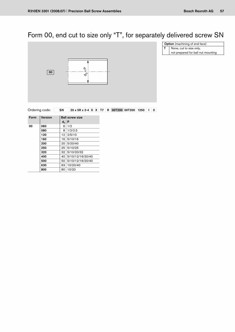
57Bosch Rexroth AG
d 0 x
P
SN 20 x 5R x 3-4 X X T7 R 00T200 00T200 1250 1 0
00
Precision Ball Screw AssembliesR310EN 3301 (2008.07)
Form 00, end cut to size only “T”, for separately delivered screw SNOption (machining of end face)T None, cut to size only,
not prepared for ball nut mounting
Ordering code:
Form Version Ball screw sized0 P
00 060 6 1/2080 8 1/2/2.5120 12 2/5/10160 16 5/10/16200 20 5/20/40250 25 5/10/25320 32 5/10/20/32400 40 5/10/12/16/20/40500 50 5/10/12/16/20/40630 63 10/20/40800 80 10/20

58 Bosch Rexroth AG
D2
S1 S
T1
D1
L6 LS1
b x l x t
L1
L
L2
SEM-E-S 20 x 5R x 3-4 X X T7 R 02Z120 82Z120 1250 1 0
01
02
Precision Ball Screw Assemblies R310EN 3301 (2008.07)
Screw Ends
Form 01–02
Undercut for retaining ring DIN 471
Undercut form E DIN 509
Undercut form E DIN 509
Option (machining of end face)Z
Z
tZ
SStS
K None
Application
Ordering code:
The allocation of screw ends to the bearing is defined by the version.1)
Form Ver-sion1)
Size Dimensions (mm) Keyway per DIN 6885
Centering hole
Hex socket
d0 P L D1 L1 D2 L2 L6 S1 ST1 LS1 b l t Z tZ S tS
j6 h7 H13 P901 050 8 2.5 19 5 5 4 14 12 3.8 h10 0.50 – – – – – – –
060 12 2/5/10 24 6 6 5 18 16 4.8 h10 0.70 – – – – – – –100 16 5/10/16 32 10 9 8 23 20 7.6 h10 1.10 – – – – – – –120 20 5/20/40 38 12 10 10 28 25 9.6 h10 1.10 – – – – – 4 4150 20 5/20/40 39 15 11 12 28 25 11.5 h11 1.10 – – – M4 10 4 4170 25 5/10/25 45 17 12 15 33 30 14.3 h11 1.10 – – – M5 12 4 4200 32 5/10/20/32 58 20 14 18 44 40 17.0 h11 1.30 – – – M6 16 5 5250 32 5/10/20/32 69 25 15 22 54 50 21.0 h11 1.30 – – – M8 19 6 6300 40 5/10/12/16/20/40 70 30 16 28 54 50 26.6 h12 1.60 – – – M10 22 10 10350 50 5/10/12/16/20/40 82 35 17 32 65 60 30.3 h12 1.60 – – – M12 28 10 10500 63 10/20/40 107 50 20 48 87 80 45.5 h12 1.85 – – – M16 36 17 17600 80 10/20 109 60 22 58 87 80 55.0 h12 2.15 – – – M20 42 17 17
02 120 20 5/20/40 38 12 10 10 28 25 9.6 h10 1.10 3 20 1.8 – – 4 4150 20 5/20/40 39 15 11 12 28 25 11.5 h11 1.10 4 20 2.5 M4 10 4 4170 25 5/10/25 45 17 12 15 33 30 14.3 h11 1.10 5 25 3.0 M5 12 4 4200 32 5/10/20/32 58 20 14 18 44 40 17.0 h11 1.30 6 28 3.5 M6 16 5 5250 32 5/10/20/32 69 25 15 22 54 50 21.0 h11 1.30 6 36 3.5 M8 19 6 6300 40 5/10/12/16/20/40 70 30 16 28 54 50 26.6 h12 1.60 8 36 4.0 M10 22 10 10350 50 5/10/12/16/20/40 82 35 17 32 65 60 30.3 h12 1.60 10 40 5.0 M12 28 10 10500 63 10/20/40 107 50 20 48 87 80 45.5 h12 1.85 14 63 6.0 M16 36 17 17600 80 10/20 109 60 22 58 87 80 55.0 h12 2.15 16 63 6.0 M20 42 17 17

59Bosch Rexroth AGPrecision Ball Screw AssembliesR310EN 3301 (2008.07)
End bearings for screw ends form 01–02
Deep-groove ball bearing per DIN 625
Retaining ring per DIN 471
Form Ver-sion
Size Deep-groove ball bearing per DIN 625
Retaining ring per DIN 471
Desig- nation
Part number Desig- nation
Part numberd0 P
01 050 8 2,5 625.2RS R3414 048 00 4x0.4 R3410 765 00060 12 2/5/10 626.2RS R3414 043 00 5x0.6 R3410 742 00100 16 5/10/16 6200.2RS R3414 049 00 8x0.8 R3410 737 00120 20 5/20/40 6201.2RS R3414 042 00 10x1 R3410 745 00150 20 5/20/40 6202.2RS R3414 074 00 12x1 R3410 712 00170 25 5/10/25 6203.2RS R3414 050 00 15x1 R3410 748 00200 32 5/10/20/32 6204.2RS R3414 038 00 18x1.2 R3410 723 00250 32 5/10/20/32 6205.2RS R3414 063 00 22x1.2 R3410 714 00300 40 5/10/12/16/20/40 6206.2RS R3414 051 00 28x1.5 R3410 752 00350 50 5/10/12/16/20/40 6207.2RS R3414 075 00 32x1.5 R3410 753 00500 63 10/20/40 6210.2RS R3414 077 00 48x1.75 R3410 718 00600 80 10/20 6212.2RS R3414 078 00 58x2 R3410 728 00
02 120 20 5/20/40 6201.2RS R3414 042 00 10x1 R3410 745 00150 20 5/20/40 6202.2RS R3414 074 00 12x1 R3410 712 00170 25 5/10/25 6203.2RS R3414 050 00 15x1 R3410 748 00200 32 5/10/20/32 6204.2RS R3414 038 00 18x1.2 R3410 723 00250 32 5/10/20/32 6205.2RS R3414 063 00 22x1.2 R3410 714 00300 40 5/10/12/16/20/40 6206.2RS R3414 051 00 28x1.5 R3410 752 00350 50 5/10/12/16/20/40 6207.2RS R3414 075 00 32x1.5 R3410 753 00500 63 10/20/40 6210.2RS R3414 077 00 48x1.75 R3410 718 00600 80 10/20 6212.2RS R3414 078 00 58x2 R3410 728 00

60 Bosch Rexroth AG
SEM-E-S 20 x 5R x 3-4 1 2 T7 R 12Z120 41Z120 1250 1 0
b x l x t
L 1
D 2
D 1
1 LG L 2
G 1
L
11
12
Precision Ball Screw Assemblies R310EN 3301 (2008.07)
Screw Ends
Form 11–12Option (machining of end face)Z
Z
tZ
SStS
K None
Application
Ordering code:
Thread undercut DIN 76 short
Undercut form F DIN 509
Undercut form E DIN 509
The allocation of screw ends to the bearing is defined by the version.1)
Form Version1) Size Dimensions (mm) Keyway per DIN 6885
Centering hole
Hex socket
d0 P L D1 L1 D2 L2 G1 LG1 b l t Z tZ S tS
h6 h7 P911 100 16 5/10/16 48 10 18 8 20 M6x0.5 10 – – – – – – –
120 20 5/20/40 60 12 23 10 25 M10x1 12 – – – – – 4 4170 25 5/10/25 75 17 23 15 30 M15x1 22 – – – M5 12 4 4200 32 5/10/20/32 88 20 26 18 40 M17x1 22 – – – M5 12 5 5250 40 10/12/16/20/40 126 25 54 22 50 M20x1 22 – – – M6 16 5 5300 40 5 101 30 25 28 50 M25x1.5 26 – – – M8 19 8 8301 50 10/12/16/20/40 130 30 54 28 50 M25x1.5 26 – – – M8 19 8 8350 50 5 118 35 32 32 60 M30x1.5 26 – – – M10 22 10 10400 63 10/20/40 132 40 44 38 60 M35x1.5 28 – – – M12 28 12 21500 80 10/20 160 50 52 48 80 M40x1.5 28 – – – M16 36 12 12
12 120 20 5/20/40 60 12 23 10 25 M10x1 12 3 20 1.8 – – 4 4170 25 5/10/25 75 17 23 15 30 M15x1 22 5 25 3.0 M5 12 4 4200 32 5/10/20/32 88 20 26 18 40 M17x1 22 6 28 3.5 M5 12 5 5250 40 10/12/16/20/40 126 25 54 22 50 M20x1 22 6 36 3.5 M6 16 5 5300 40 5 101 30 25 28 50 M25x1.5 26 8 36 4.0 M8 19 8 8301 50 10/12/16/20/40 130 30 54 28 50 M25x1.5 26 8 36 4.0 M8 19 8 8350 50 5 118 35 32 32 60 M30x1.5 26 10 40 5.0 M10 22 10 10400 63 10/20/40 132 40 44 38 60 M35x1.5 28 10 40 5.0 M12 28 12 12500 80 10/20 160 50 52 48 80 M40x1.5 28 14 63 5.5 M16 36 12 12

61Bosch Rexroth AGPrecision Ball Screw AssembliesR310EN 3301 (2008.07)
End bearings for screw ends form 11–12
Angular-contact thrust ball bearing LGN
Angular-contact thrust ball bearing LGF
Slotted nut NMZ Slotted nut NMA
Form Ver-sion
Size Angular-contact thrust ball bearing Slotted nut
d0 P LGFDesignation
Part number
LGNDesignation
Part number
Designation
Part number
11 100 16 5/10/16 – – LGN-B-1034 R3414 003 06 NMZ6x0.5 R3446 001 04120 20 5/20/40 LGF-B-1255 R3414 009 06 LGN-B-1242 R3414 004 06 NMZ10x1 R3446 002 04170 25 5/10/25 LGF-B-1762 R3414 010 06 LGN-B-1747 R3414 005 06 NMA15x1 R3446 020 04200 32 5/10/20/32 LGF-B-2068 R3414 001 06 LGN-B-2052 R3414 006 06 NMA17x1 R3446 014 04250 40 10/12/16/20/40 LGF-C-2575 R3414 015 06 LGN-C-2557 R3414 014 06 NMA20x1 R3446 015 04300 40 5 LGF-B-3080 R3414 011 06 LGN-B-3062 R3414 007 06 NMA25x1.5 R3446 011 04301 50 10/12/16/20/40 LGF-C-3080 R3414 027 06 LGN-C-3062 R3414 023 06 NMA25x1.5 R3446 011 04350 50 5 LGF-B-3590 R3414 026 06 LGN-B-3572 R3414 022 06 NMA30x1.5 R3446 016 04400 63 10/20/40 LGF-B-40115 R3414 028 06 LGN-A-4090 R3414 024 06 NMA35x1.5 R3446 012 04500 80 10/20 LGF-A-50140 R3414 029 06 LGN-A-50110 R3414 025 06 NMA40x1.5 R3446 018 04
12 120 20 5/20/40 LGF-B-1255 R3414 009 06 LGN-B-1242 R3414 004 06 NMZ10x1 R3446 002 04170 25 5/10/25 LGF-B-1762 R3414 010 06 LGN-B-1747 R3414 005 06 NMA15x1 R3446 020 04200 32 5/10/20/32 LGF-B-2068 R3414 001 06 LGN-B-2052 R3414 006 06 NMA17x1 R3446 014 04250 40 10/12/16/20/40 LGF-B-2575 R3414 015 06 LGN-C-2557 R3414 014 06 NMA20x1 R3446 015 04300 40 5 LGF-B-3080 R3414 011 06 LGN-B-3062 R3414 007 06 NMA25x1.5 R3446 011 04301 50 10/12/16/20/40 LGF-C-3080 R3414 027 06 LGN-C-3062 R3414 023 06 NMA25x1.5 R3446 011 04350 50 5 LGF-B-3590 R3414 026 06 LGN-B-3572 R3414 022 06 NMA30x1.5 R3446 016 04400 63 10/20/40 LGF-B-40115 R3414 028 06 LGN-A-4090 R3414 024 06 NMA35x1.5 R3446 012 04500 80 10/20 LGF-A-50140 R3414 029 06 LGN-A-50110 R3414 025 06 NMA40x1.5 R3446 018 04

62 Bosch Rexroth AG
SEM-E-S 20 x 5R x 3-4 1 2 T7 R 21Z120 82Z120 1250 1 0
D1
L1
21
Precision Ball Screw Assemblies R310EN 3301 (2008.07)
Screw Ends
Option (machining of end face)Z
Z
tZ
SStS
K None
Application
Ordering code:
Form 21
Undercut form E DIN 509
Form Version1) Size Dimensions (mm)
Centering hole
Hex socket
d0 P D1 L1 Z tZ S tS
j621 050 8 2.5 5 5 – – – –
060 12 2/5/10 6 6 – – – –100 16 5/10/16 10 9 – – 4 4120 20 5/20/40 12 10 M4 10 4 4150 20 5/20/40 15 11 M5 12 4 4170 25 5/10/25 17 12 M6 16 5 5200 32 5/10/20/32 20 14 M6 19 5 5250 32 5/10/20/32 25 15 M10 22 8 8300 40 5 30 16 M10 22 10 10300 40 10/12/16/20/40 30 16 M10 22 10 10350 50 5 35 17 M12 18 12 12350 50 10/12/16/20/40 35 17 M12 18 12 12500 63 10/20/40 50 20 M16 36 17 17600 80 10/20 60 22 M20 42 17 17
The allocation of screw ends to the bearing is defined by the version.1)

63Bosch Rexroth AGPrecision Ball Screw AssembliesR310EN 3301 (2008.07)
End bearings for screw ends form 21
Pillow block unit SEB-L
Bearing LAD2)
Form Version Size
Pillow block unit SEB-L
Bearing LAD2)
d0 P Part number Part number21 050 8 2.5 R1591 605 00 R1590 605 00
060 12 2/5/10 R1591 606 20 R1590 606 00100 16 5/10/16 R1591 610 20 R1590 610 00120 20 5/20/40 R1591 612 20 R1590 612 00150 20 5/20/40 – R1590 615 00170 25 5/10/25 R1591 617 20 R1590 617 00200 32 5/10/20/32 R1591 620 20 R1590 620 00250 32 5/10/20/32 – R1590 625 00300 40 5 R1591 630 20 R1590 630 00300 40 10/12/16/20/40 R1591 630 10350 50 5 R1591 635 10 R1590 635 00350 50 10/12/16/20/40 R1591 635 20500 63 10/20/40 R1591 650 20 R1590 650 00600 80 10/20 R1591 660 20 R1590 660 00
Items delivered: 1 bearing, 2 retaining rings.2)

64 Bosch Rexroth AG
SEM-E-S 20 x 5R x 3-4 1 2 T7 R 31Z120 82Z120 1250 1 0
L 5
L 4 L 4 LS 1
L 1
S 1 D
1 ST 1
31
Precision Ball Screw Assemblies R310EN 3301 (2008.07)
Screw Ends
Option (machining of end face)Z
Z
tZ
SStS
K None
Application
Ordering code:
The allocation of screw ends to the bearing is defined by the version. Note: Form 31 with double floating bearing increases the critical speed, see page 124.
1)
Form 31
Undercut for retaining ring DIN 471 (3x)
Undercut form E DIN 509
Form Version1) Size Dimensions (mm) Centering hole Hex socket
d0 P D1 L1 L4 L5 S1 ST1 LS1 Z tZ S tS
j6 H1331 050 8 2.5 5 22 5 20 4.8 h10 0.70 – – – –
060 12 2/5/10 6 26 6 24 5.7 h10 0.80 – – – –100 16 5/10/16 10 39 9 36 9.6 h10 1.10 – – 4 4120 20 5/20/40 12 43 10 40 11.5 h11 1.10 M4 10 4 4150 20 5/20/40 15 47 11 44 14.3 h11 1.10 M5 12 4 4170 25 5/10/25 17 51 12 48 16.2 h11 1.10 M6 16 5 5200 32 5/10/20/32 20 60 14 56 19.0 h11 1.30 M6 16 5 5250 32 5/10/20/32 25 64 15 60 23.9 h12 1.30 M10 22 8 8300 40 5/10/12/16/20/40 30 68 16 64 28.6 h12 1.60 M10 22 10 10350 50 5/10/12/16/20/40 35 73 17 68 33.0 h12 1.60 M12 28 12 12500 63 10/20/40 50 87 20 80 47.0 h12 2.15 M16 36 17 17600 80 10/20 60 95 22 88 57.0 h12 2.15 M20 42 17 17

65Bosch Rexroth AGPrecision Ball Screw AssembliesR310EN 3301 (2008.07)
End bearings for screw ends form 31
Pillow block unit SEC-L
Bearing LAD2)
Items delivered per bearing LAD: 1 bearing, 2 retaining rings. Two sets are required for applications with Form 31.
2)
Form Version SizePillow block unit SEC-L Part number
BearingLAD2)
Part numberd0 P31 050 8 2.5 – R1590 605 00
060 12 2/5/10 – R1590 606 00100 16 5/10/16 – R1590 610 00120 20 5/20/40 – R1590 612 00150 20 5/20/40 R1594 615 00 R1590 615 00170 25 5/10/25 – R1590 617 00200 32 5/10/20/32 R1594 620 00 R1590 620 00250 32 5/10/20/32 – R1590 625 00300 40 5/10/12/16/20/40 R1594 630 00 R1590 630 00350 50 5/10/12/16/20/40 – R1590 635 00500 63 10/20/40 – R1590 650 00600 80 10/20 – R1590 660 00
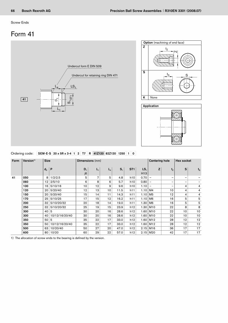
66 Bosch Rexroth AG
L 4 LS 1
D 1
S 1
L 1
ST 1
SEM-E-S 20 x 5R x 3-4 1 2 T7 R 41Z120 82Z120 1250 1 0
41
Precision Ball Screw Assemblies R310EN 3301 (2008.07)
Undercut for retaining ring DIN 471
Undercut form E DIN 509
Form 41
Screw Ends
Option (machining of end face)Z
Z
tZ
SStS
K None
Application
Ordering code:
The allocation of screw ends to the bearing is defined by the version.1)
Form Version1) Size Dimensions (mm) Centering hole Hex socket
d0 P D1 L1 L4 S1 ST1 LS1 Z tZ S tS
j6 H1341 050 8 1/2/2.5 5 7 5 4.8 h10 0.70 – – – –
060 12 2/5/10 6 8 6 5.7 h10 0.80 – – – –100 16 5/10/16 10 12 9 9.6 h10 1.10 – – 4 4120 20 5/20/40 12 13 10 11.5 h11 1.10 M4 10 4 4150 20 5/20/40 15 14 11 14.3 h11 1.10 M5 12 4 4170 25 5/10/25 17 15 12 16.2 h11 1.10 M6 16 5 5200 32 5/10/20/32 20 18 14 19.0 h11 1.30 M6 16 5 5250 32 5/10/20/32 25 19 15 23.9 h12 1.30 M10 22 8 8300 40 5 30 20 16 28.6 h12 1.60 M10 22 10 10300 40 10/12/16/20/40 30 20 16 28.6 h12 1.60 M10 22 10 10350 50 5 35 22 17 33.0 h12 1.60 M12 28 12 12350 50 10/12/16/20/40 35 22 17 33.0 h12 1.60 M12 28 12 12500 63 10/20/40 50 27 20 47.0 h12 2.15 M16 36 17 17600 80 10/20 60 29 22 57.0 h12 2.15 M20 42 17 17

67Bosch Rexroth AGPrecision Ball Screw AssembliesR310EN 3301 (2008.07)
Pillow block unit SEB-L
Bearing LAD2)
End bearings for screw ends form 41
Form Version SizeBearing LAD2)
Part number
Pillow block unit SEB-L Part numberd0 P
41 050 8 1/2/2.5 R1590 605 00 R1591 605 00060 12 2/5/10 R1590 606 00 R1591 606 20100 16 5/10/16 R1590 610 00 R1591 610 20120 20 5/20/40 R1590 612 00 R1591 612 20150 20 5/20/40 R1590 615 00 –170 25 5/10/25 R1590 617 00 R1591 617 20200 32 5/10/20/32 R1590 620 00 R1591 620 20250 32 5/10/20/32 R1590 625 00 –300 40 5 R1590 630 00 R1591 630 20300 40 10/12/16/20/40 R1590 630 00 R1591 630 10350 50 5 R1590 635 00 R1591 635 10350 50 10/12/16/20/40 R1590 635 00 R1591 635 20500 63 10/20/40 R1590 650 00 R1591 650 20600 80 10/20 R1590 660 00 R1591 660 20
Items delivered: 1 bearing, 2 retaining rings.2)

68 Bosch Rexroth AG
max . 8 15 L1
L
L
D 1
L 1
LG
G 1
∅ 12
1
LG 1
SEM-E-S 20 x 5R x 3-4 1 2 T7 R 51Z120 82Z120 1250 1 0
51
53
Precision Ball Screw Assemblies R310EN 3301 (2008.07)
Screw Ends
Option (machining of end face)Z
Z
tZ
SStS
K None
Application
Ordering code:
The allocation of screw ends to the bearing is defined by the version.1)
Form Version1) Size Dimensions (mm) Centering hole Hex socket
d0 P L D1 L1 G1 LG1 Z tZ S tS
h651 060 12 2/5/10 24 6 14 M6x0.5 10 – – – –
100 16 5/10/16 30 10 18 M10x1 12 – – 4 4120 20 5/20/40 35 12 23 M12x1 12 M4 10 4 4170 25 5/10/25 45 17 23 M17x1 22 M5 12 5 5200 32 5/10/20/32 48 20 26 M20x1 22 M6 16 5 5250 40 10/12/16/20/40 80 25 54 M25x1.5 26 M8 19 8 8300 40 5 51 30 25 M30x1.5 26 M10 22 10 10300 40 10/12/16/20/40 51 30 25 M30x1.5 26 M10 22 10 10301 50 10/12/16/20/40 80 30 54 M30x1.5 26 M10 22 10 10350 50 5 60 35 32 M35x1.5 28 M12 28 12 12400 63 10/20/40 72 40 44 M40x1.5 28 M16 36 12 12500 80 10/20 84 50 52 M50x1.5 32 M16 36 17 17
53 060 8 2.5 24 6 14 M6x0.5 10 – – – –
Form 51–53
Thread undercut DIN 76 short
Undercut form F DIN 509
8 x 2.5 only
Mechanically connected

69Bosch Rexroth AGPrecision Ball Screw AssembliesR310EN 3301 (2008.07)
Pillow block unit SEB-F
Bearing LAN Bearing LAF
End bearings for screw ends form 51–53
Form Ver-sion
SizePillow block unitSEB-FPart number
Bearing BearingLAF LAN
d0 P Part number Part number51 060 12 2/5/10 R1591 106 20 – R1590 106 00
100 16 5/10/16 R1591 110 20 – R1590 110 00120 20 5/20/40 R1591 112 20 R1590 012 00 R1590 112 00170 25 5/10/25 R1591 117 30 R1590 017 30 R1590 117 30200 32 5/10/20/32 R1591 120 30 R1590 020 30 R1590 120 30250 40 10/12/16/20/40 R1591 225 30 R1590 325 30 R1590 225 30300 40 5 R1591 130 30 R1590 030 30 R1590 130 30300 40 10/12/16/20/40 – – –301 50 10/12/16/20/40 R1591 230 30 R1590 330 30 R1590 230 30350 50 5 R1591 135 30 R1590 035 30 R1590 135 30400 63 10/20/40 R1591 140 30 R1590 040 30 R1590 140 30500 80 10/20 R1591 150 30 R1590 050 30 R1590 150 30
53 060 8 2.5 R1591 106 00 – R1590 106 00

70 Bosch Rexroth AG
SEM-E-S 20 x 5R x 3-4 1 2 T7 R 62Z120 51Z120 1250 1 0
L 4 L 4 LS 1
D 1
S 1 S
T1
D 2
b x l x t
L 5
L 2 L 1
L
61
62
Precision Ball Screw Assemblies R310EN 3301 (2008.07)
Undercut for retaining ring DIN 471 (3x)
Undercut form E DIN 509
Form 61–62
Undercut form E DIN 509
Screw Ends
Option (machining of end face)Z
Z
tZ
SStS
K None
Application
Ordering code:
The allocation of screw ends to the bearing is defined by the version.1)
Form Version1) Size Dimensions (mm) Keyway per DIN 6885
Centering hole Hex socket
d0 P L D1 L1 D2 L2 L4 L5 S1 ST1 LS1 b l t Z tZ S tS
j6 h7 H13 P961 050 8 2.5 34 5 22 4 12 5 20 4.8 h10 0.70 – – – – – – –
060 12 2/5/10 42 6 26 5 16 6 24 5.7 h10 0.80 – – – – – – –100 16 5/10/16 59 10 39 8 20 9 36 9.6 h10 1.10 – – – – – – –120 20 5/20/40 68 12 43 10 25 10 40 11.5 h11 1.10 – – – – – 4 4150 20 5/20/40 72 15 47 12 25 11 44 14.3 h11 1.10 – – – M4 10 4 4170 25 5/10/25 81 17 51 15 30 12 48 16.2 h11 1.10 – – – M5 12 4 4200 32 5/10/20/32 100 20 60 18 40 14 56 19.0 h11 1.30 – – – M6 16 5 5250 32 5/10/20/32 114 25 64 22 50 15 60 23.9 h12 1.30 – – – M8 19 6 6300 40 5/10/12/16/20/40 118 30 68 28 50 16 64 28.6 h12 1.60 – – – M10 22 10 10350 50 5/10/12/16/20/40 133 35 73 32 60 17 68 33.0 h12 1.60 – – – M12 28 10 10500 63 10/20/40 167 50 87 48 80 20 80 47.0 h12 2.15 – – – M16 36 17 17600 80 10/20 175 60 95 58 80 22 88 57.0 h12 2.15 – – – M20 42 17 17
62 120 20 5/20/40 68 12 43 10 25 10 40 11.5 h11 1.10 3 20 1.8 – – 4 4150 20 5/20/40 72 15 47 12 25 11 44 14.3 h11 1.10 4 20 2.5 M4 10 4 4170 25 5/10/25 81 17 51 15 30 12 48 16.2 h11 1.10 5 25 3.0 M5 12 4 4200 32 5/10/20/32 100 20 60 18 40 14 56 19.0 h11 1.30 6 28 3.5 M6 16 5 5250 32 5/10/20/32 114 25 64 22 50 15 60 23.9 h12 1.30 6 36 3.5 M8 19 6 6300 40 5/10/12/16/20/40 118 30 68 28 50 16 64 28.6 h12 1.60 8 36 4.0 M10 22 10 10350 50 5/10/12/16/20/40 133 35 73 32 60 17 68 33.0 h12 1.60 10 40 5.0 M12 28 10 10500 63 10/20/40 167 50 87 48 80 20 80 47.0 h12 2.15 14 63 5.5 M16 36 17 17600 80 10/20 175 60 95 58 80 22 88 57.0 h12 2.15 16 63 6.0 M20 46 17 17

71Bosch Rexroth AGPrecision Ball Screw AssembliesR310EN 3301 (2008.07)
End bearings for screw ends form 61–62
Bearing LAD2)
Items delivered per bearing: 1 bearing, 2 retaining rings. Two sets are required for applications with Form 61–62.
2)
Form Version SizeBearingLAD2)
d0 P Part number61 050 8 2.5 R1590 605 00
060 12 2/5/10 R1590 606 00100 16 5/10/16 R1590 610 00120 20 5/20/40 R1590 612 00150 20 5/20/40 R1590 615 00170 25 5/10/25 R1590 617 00200 32 5/10/20/32 R1590 620 00250 32 5/10/20/32 R1590 625 00300 40 5/10/12/16/20/40 R1590 630 00350 50 5/10/12/16/20/40 R1590 635 00500 63 10/20/40 R1590 650 00600 80 10/20 R1590 660 00
62 120 20 5/20 R1590 612 00150 20 5/20 R1590 615 00170 25 5/10/25 R1590 617 00200 32 5/10/20/32 R1590 620 00250 32 5/10/20/32 R1590 625 00300 40 5/10/12/16/20/40 R1590 630 00350 50 5/10/12/16/20/40 R1590 635 00500 63 10/20/40 R1590 650 00600 80 10/20 R1590 660 00

72 Bosch Rexroth AG
SEM-E-S 20 x 5R x 3-4 1 2 T7 R 72Z120 51Z120 1250 1 0
D 1
b x l x t
1 L L 2
L 4 LS 1
L
S 1 S
T1
D 2 71
72
Precision Ball Screw Assemblies R310EN 3301 (2008.07)
Screw Ends
Option (machining of end face)Z
Z
tZ
SStS
K None
Application
Ordering code:
The allocation of screw ends to the bearing is defined by the version.1)
Form Version1) Size Dimensions (mm) Keyway per DIN 6885
Centering hole Hex socket
d0 P L D1 L1 D2 L2 L4 S1 ST1 LS1 b l t Z tZ S tS
j6 h7 H13 P971 050 8 2.5 19 5 7 4 12 5 4.8 h10 0.70 – – – – – – –
060 12 2/5/10 24 6 8 5 16 6 5.7 h10 0.80 – – – – – – –100 16 5/10/16 32 10 12 8 20 9 9.6 h10 1.10 – – – – – – –120 20 5/20/40 38 12 13 10 25 10 11.5 h11 1.10 – – – – – 4 4150 20 5/20/40 39 15 14 12 25 11 14.3 h11 1.10 – – – M4 10 4 4170 25 5/10/25 45 17 15 15 30 12 16.2 h11 1.10 – – – M5 12 4 4200 32 5/10/20/32 58 20 18 18 40 14 19.0 h11 1.30 – – – M6 16 5 5250 32 5/10/20/32 69 25 19 22 50 15 23.9 h12 1.30 – – – M8 19 6 6300 40 5/10/12/16/20/40 70 30 20 28 50 16 28.6 h12 1.60 – – – M10 22 10 10350 50 5/10/12/16/20/40 82 35 22 32 60 17 33.0 h12 1.60 – – – M12 28 10 10500 63 10/20/40 107 50 27 48 80 20 47.0 h12 2.15 – – – M16 36 17 17600 80 10/20 109 60 29 58 80 22 57.0 h12 2.15 – – – M20 42 17 17
72 120 20 5/20/40 38 12 13 10 25 10 11.5 h11 1.10 3 20 1.8 – – 4 4150 20 5/20/40 39 15 14 12 25 11 14.3 h11 1.10 4 20 2.5 M4 10 4 4170 25 5/10/25 45 17 15 15 30 12 16.2 h11 1.10 5 25 3.0 M5 12 4 4200 32 5/10/20/32 58 20 18 18 40 14 19.0 h11 1.30 6 28 3.5 M6 16 5 5250 32 5/10/20/32 69 25 19 22 50 15 23.9 h12 1.30 6 36 3.5 M8 19 6 6300 40 5/10/12/16/20/40 70 30 20 28 50 16 28.6 h12 1.60 8 36 4.0 M10 22 10 10350 50 5/10/12/16/20/40 82 35 22 32 60 17 33.0 h12 1.60 10 40 5.0 M12 28 10 10500 63 10/20/40 107 50 27 48 80 20 47.0 h12 2.15 14 63 5.5 M16 36 17 17600 80 10/20 109 60 29 58 80 22 57.0 h12 2.15 16 63 6.0 M20 42 17 17
Undercut for retaining ring DIN 471
Undercut form E DIN 509
Form 71–72
Undercut form E DIN 509

73Bosch Rexroth AGPrecision Ball Screw AssembliesR310EN 3301 (2008.07)
End bearings for screw ends form 71–72
Bearing LAD2)
Form Version SizeBearingLAD2)
Part numberd0 P71 050 8 2.5 R1590 605 00
060 12 2/5/10 R1590 606 00100 16 5/10/16 R1590 610 00120 20 5/20/40 R1590 612 00150 20 5/20/40 R1590 615 00170 25 5/10/25 R1590 617 00200 32 5/10/20/32 R1590 620 00250 32 5/10/20/32 R1590 625 00300 40 5/10/12/16/20/40 R1590 630 00350 50 5/10/12/16/20/40 R1590 635 00500 63 10/20/40 R1590 650 00600 80 10/20 R1590 660 00
72 120 20 5/20/40 R1590 612 00150 20 5/20/40 R1590 615 00170 25 5/10/25 R1590 617 00200 32 5/10/20/32 R1590 620 00250 32 5/10/20/32 R1590 625 00300 40 5/10/12/16/20/40 R1590 630 00350 50 5/10/12/16/20/40 R1590 635 00500 63 10/20/40 R1590 650 00600 80 10/20 R1590 660 00
Items delivered: 1 bearing, 2 retaining rings.2)
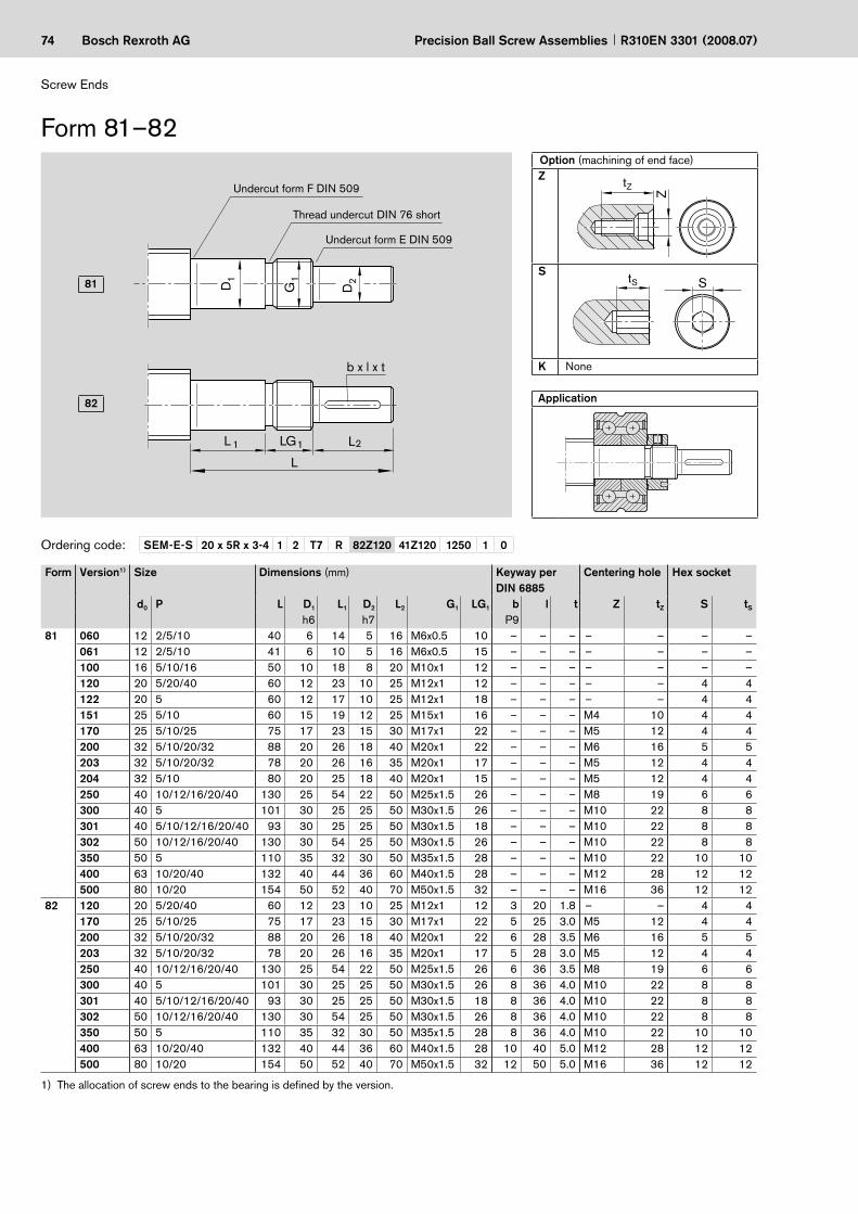
74 Bosch Rexroth AG
G1
b x l x t
max. 8 15 L
∅12
D2
L 1 1LG L2
L
D1
SEM-E-S 20 x 5R x 3-4 1 2 T7 R 82Z120 41Z120 1250 1 0
81
82
Precision Ball Screw Assemblies R310EN 3301 (2008.07)
Thread undercut DIN 76 short
Undercut form E DIN 509
Undercut form F DIN 509
Form 81–82
Screw Ends
Option (machining of end face)Z
Z
tZ
SStS
K None
Application
Ordering code:
The allocation of screw ends to the bearing is defined by the version.1)
Form Version1) Size Dimensions (mm) Keyway per DIN 6885
Centering hole Hex socket
d0 P L D1 L1 D2 L2 G1 LG1 b l t Z tZ S tS
h6 h7 P981 060 12 2/5/10 40 6 14 5 16 M6x0.5 10 – – – – – – –
061 12 2/5/10 41 6 10 5 16 M6x0.5 15 – – – – – – –100 16 5/10/16 50 10 18 8 20 M10x1 12 – – – – – – –120 20 5/20/40 60 12 23 10 25 M12x1 12 – – – – – 4 4122 20 5 60 12 17 10 25 M12x1 18 – – – – – 4 4151 25 5/10 60 15 19 12 25 M15x1 16 – – – M4 10 4 4170 25 5/10/25 75 17 23 15 30 M17x1 22 – – – M5 12 4 4200 32 5/10/20/32 88 20 26 18 40 M20x1 22 – – – M6 16 5 5203 32 5/10/20/32 78 20 26 16 35 M20x1 17 – – – M5 12 4 4204 32 5/10 80 20 25 18 40 M20x1 15 – – – M5 12 4 4250 40 10/12/16/20/40 130 25 54 22 50 M25x1.5 26 – – – M8 19 6 6300 40 5 101 30 25 25 50 M30x1.5 26 – – – M10 22 8 8301 40 5/10/12/16/20/40 93 30 25 25 50 M30x1.5 18 – – – M10 22 8 8302 50 10/12/16/20/40 130 30 54 25 50 M30x1.5 26 – – – M10 22 8 8350 50 5 110 35 32 30 50 M35x1.5 28 – – – M10 22 10 10400 63 10/20/40 132 40 44 36 60 M40x1.5 28 – – – M12 28 12 12500 80 10/20 154 50 52 40 70 M50x1.5 32 – – – M16 36 12 12
82 120 20 5/20/40 60 12 23 10 25 M12x1 12 3 20 1.8 – – 4 4170 25 5/10/25 75 17 23 15 30 M17x1 22 5 25 3.0 M5 12 4 4200 32 5/10/20/32 88 20 26 18 40 M20x1 22 6 28 3.5 M6 16 5 5203 32 5/10/20/32 78 20 26 16 35 M20x1 17 5 28 3.0 M5 12 4 4250 40 10/12/16/20/40 130 25 54 22 50 M25x1.5 26 6 36 3.5 M8 19 6 6300 40 5 101 30 25 25 50 M30x1.5 26 8 36 4.0 M10 22 8 8301 40 5/10/12/16/20/40 93 30 25 25 50 M30x1.5 18 8 36 4.0 M10 22 8 8302 50 10/12/16/20/40 130 30 54 25 50 M30x1.5 26 8 36 4.0 M10 22 8 8350 50 5 110 35 32 30 50 M35x1.5 28 8 36 4.0 M10 22 10 10400 63 10/20/40 132 40 44 36 60 M40x1.5 28 10 40 5.0 M12 28 12 12500 80 10/20 154 50 52 40 70 M50x1.5 32 12 50 5.0 M16 36 12 12

75Bosch Rexroth AGPrecision Ball Screw AssembliesR310EN 3301 (2008.07)
Pillow block unit SEB-F
Bearing LAN
Pillow block unit SEC-F
End bearings for screw ends form 81–82
Bearing LAF Bearing LAL
Form Version Size Pillow block unit for motor attachment Bearing
LAFBearing LAN
Bearing LALSEC-F SEB-F
d0 P Part number Part number Part number Part number Part number81 060 12 2/5/10 – R1591 106 20 – R1590 106 00 –
061 12 2/5/10 – – – – R1590 406 00100 16 5/10/16 – R1591 110 20 – R1590 110 00 –120 20 5/20/40 R1594 012 00 R1591 112 20 R1590 012 00 R1590 112 00 –122 20 5 – – – – R1590 412 00151 25 5/10 – – – – R1590 415 00170 25 5/10/25 – R1591 117 30 R1590 017 30 R1590 117 30 –200 32 5/10/20/32 – R1591 120 30 R1590 020 30 R1590 120 30 –203 32 5/10/20/32 R1594 020 00 – R1590 020 00 R1590 120 00 –204 32 5/10 – – – – R1590 420 00250 40 10/12/16/20/40 – R1591 225 30 R1590 325 30 R1590 225 30 –300 40 5 – R1591 130 30 R1590 030 30 R1590 130 30 –301 40 5/10/12/16/20/40 R1594 030 00 – – – –302 50 10/12/16/20/40 – R1591 230 30 R1590 330 30 R1590 230 30 –350 50 5 – R1591 135 30 R1590 035 30 R1590 135 30 –400 63 10/20/40 – R1591 140 30 R1590 040 30 R1590 140 30 –500 80 10/20 – R1591 150 30 R1590 050 30 R1590 150 30 –
82 120 20 5/20/40 R1594 012 00 R1591 112 20 R1590 012 00 R1590 112 00 –170 25 5/10/25 – R1591 117 30 R1590 017 30 R1590 117 30 –200 32 5/10/20/32 – R1591 120 30 R1590 020 30 R1590 120 30 –203 32 5/10/20/32 R1594 020 00 – R1590 020 00 R1590 120 00 –250 40 10/12/16/20/40 – R1591 225 30 R1590 325 30 R1590 225 30 –300 40 5 – R1591 130 30 R1590 030 30 R1590 130 30 –301 40 5/10/12/16/20/40 R1594 030 00 – – – –302 50 10/12/16/20/40 – R1591 230 30 R1590 330 30 R1590 230 30 –350 50 5 – R1591 135 30 R1590 035 30 R1590 135 30 –400 63 10/20/40 – R1591 140 30 R1590 040 30 R1590 140 30 –500 80 10/20 – R1591 150 30 R1590 050 30 R1590 150 30 –

76 Bosch Rexroth AG
SEM-E-S 20 x 5R x 3-4 1 2 T7 R 83Z200 51Z120 1250 1 0
L L F R L ZF
L 1 LG 1 L 2
b x l x t
D 1
G 1
D 2
D R D F 83
84
Precision Ball Screw Assemblies R310EN 3301 (2008.07)
Thread undercut DIN 76 short
Undercut form E DIN 509
Undercut form F DIN 509
Form 83–84
Mechanically connected
Screw Ends
Option (machining of end face)Z
Z
tZ
SStS
K None
Application
Ordering code:
Form Version Size Dimensions (mm) Keyway per DIN 6885
Centering hole Hex socket
d0 P LZF D1 L1 D2 L2 G1 LG1 b l t Z tZ S tS
h6 h7 P983–84 060 6 all 40 6 14 5 16 M6x0.5 10 – – – – – – –
061 6 1/2 41 6 10 5 16 M6x0.5 15 – – – – – – –060 8 all 40 6 14 5 16 M6x0.5 10 – – – – – – –062 8 1 41 6 10 5 16 M6x0.5 15 – – – – – – –063 8 2 41 6 10 5 16 M6x0.5 15 – – – – – – –064 8 2.5 41 6 10 5 16 M6x0.5 15 – – – – – – –120 12 all 60 12 23 10 25 M12x1 12 3 20 1.8 – – 4 4121 12 5/10 60 12 17 10 25 M12x1 18 – – – – – 4 4122 16 5/10 60 12 17 10 25 M12x1 18 – – – – – 4 4170 16 all 75 17 23 15 30 M17x1 22 4 20 2.5 M5 12 4 4200 20 all 88 20 26 18 40 M20x1 22 6 28 3.5 M6 16 5 5250 25 all 102 25 26 22 50 M25x1.5 26 6 36 3.5 M8 19 6 6300 32 all 101 30 25 25 50 M30x1.5 26 8 36 4.0 M10 22 8 8400 40 all 132 40 44 36 60 M35x1.5 28 10 40 5.0 M12 28 12 12500 50 all 154 50 52 40 70 M50x1.5 32 12 50 5.0 M16 36 12 12600 63 all 155 60 43 55 80 M60x2 32 16 63 6.0 M20 42 17 17

77Bosch Rexroth AGPrecision Ball Screw AssembliesR310EN 3301 (2008.07)
End bearings for screw ends form 83–84
Bearing LAF Bearing LAN
Bearing LAL
Shown with slotted nut NMZShown with slotted nut NMA
Form Version Size Mechanical connectionDimensions (mm) Bearing
LAFBearing LAN
Bearing LAL
d0 P DR LR DF LF max Part number Part number Part number83–84 060 6 all 12 15 5.2 8 – R1590 106 00 –
061 6 1/2 12 15 5.2 8 – – R1590 406 00060 8 all 12 15 6.2 8 – R1590 106 00 –062 8 1 12 15 7.2 8 – – R1590 406 00063 8 2 12 15 6.9 8 – – R1590 406 00064 8 2.5 12 15 6.2 8 – – R1590 406 00120 12 all 16 15 9.5 8 – R1590 112 00 –121 12 5/10 15 15 9.5 8 – – R1590 412 00122 16 5/10 15 15 12.5 8 – – R1590 412 00170 16 all 23 15 12.5 8 R1590 017 30 R1590 117 30 –200 20 all 25 15 16.5 8 R1590 020 30 R1590 120 30 –250 25 all 32 15 21.0 8 R1590 325 30 R1590 225 30 –300 32 all 40 20 28.0 8 R1590 030 30 R1590 130 30 –400 40 all 50 20 33.5 8 R1590 040 30 R1590 140 30 –500 50 all 63 20 43.5 8 R1590 050 30 R1590 150 30 –600 63 all 82 25 56.0 8 – – –

78 Bosch Rexroth AG
G 1
b x l x t
max . 8 15 L
L 1 1 L 2 L 3
L
D 1
D 2
D 3
∅ 12
LG
SEM-E-S 20 x 5R x 3-4 1 2 T7 R 92K120 41Z120 1250 1 0
91
92
Precision Ball Screw Assemblies R310EN 3301 (2008.07)
Screw Ends
Option (machining of end face)K None
Application
Ordering code:
The allocation of screw ends to the bearing is defined by the version.1)
Form Version1) Size Dimensions (mm) Keyway per DIN 6885
d0 P L D1 L1 D2 L2 D3 L3 G1 LG1 b l th6 h7 h7 P9
91 060 12 2/5/10 50 6 14 5 16 4 10 M6x0.5 10 – – –100 16 5/10/16 60 10 18 8 20 4 10 M10x1 12 – – –120 20 5/20/40 75 12 23 10 25 6 15 M12x1 12 – – –170 25 5/10/25 90 17 23 15 30 6 15 M17x1 22 – – –200 32 5/10/20/32 103 20 26 18 40 6 15 M20x1 22 – – –250 40 10/12/16/20/40 145 25 54 22 50 6 15 M25x1.5 26 – – –300 40 5 116 30 25 25 50 6 15 M30x1.5 26 – – –301 50 10/12/16/20/40 145 30 54 25 50 6 15 M30x1.5 26 – – –350 50 5 125 35 32 30 50 6 15 M35x1.5 28 – – –400 63 10/20/40 147 40 44 36 60 6 15 M40x1.5 28 – – –500 80 10/20 169 50 52 40 70 6 15 M50x1.5 32 – – –
92 120 20 5/20/40 75 12 23 10 25 6 15 M12x1 12 3 20 1.8170 25 5/10/25 90 17 23 15 30 6 15 M17x1 22 5 25 3.0200 32 5/10/20/32 103 20 26 18 40 6 15 M20x1 22 6 28 3.5250 40 10/12/16/20/40 145 25 54 22 50 6 15 M25x1.5 26 6 36 3.5300 40 5 116 30 25 25 50 6 15 M30x1.5 26 8 36 4.0301 50 10/12/16/20/40 145 30 54 25 50 6 15 M30x1.5 26 8 36 4.0350 50 5 125 35 32 30 50 6 15 M35x1.5 28 8 36 4.0400 63 10/20/40 147 40 44 36 60 6 15 M40x1.5 28 10 40 5.0500 80 10/20 169 50 52 40 70 6 15 M50x1.5 32 12 50 5.0
Thread undercut DIN 76 short
Undercut form E DIN 509
Undercut form F DIN 509
Form 91–92

79Bosch Rexroth AGPrecision Ball Screw AssembliesR310EN 3301 (2008.07)
Pillow block unit SEB-F
Bearing LAN
End bearings for screw ends form 91–92
Bearing LAF
Shown with slotted nut NMZShown with slotted nut NMA
Form Version1) SizePillow block unitSEB-F
Bearing LAF
Bearing LAN
d0 P Part number Part number Part number91 060 12 2/5/10 R1591 106 20 – R1590 106 00
100 16 5/10/16 R1591 110 20 – R1590 110 00120 20 5/20/40 R1591 112 20 R1590 012 00 R1590 112 00170 25 5/10/25 R1591 117 30 R1590 017 30 R1590 117 30200 32 5/10/20/32 R1591 120 30 R1590 020 30 R1590 120 30250 40 10/12/16/20/40 R1591 225 30 R1590 325 30 R1590 225 30300 40 5 R1591 130 30 R1590 030 30 R1590 130 30301 50 10/12/16/20/40 R1591 230 30 R1590 330 30 R1590 230 30350 50 5 R1591 135 30 R1590 035 30 R1590 135 30400 63 10/20/40 R1591 140 30 R1590 040 30 R1590 140 30500 80 10/20 R1591 150 30 R1590 050 30 R1590 150 30
92 120 20 5/20/40 R1591 112 20 R1590 012 00 R1590 112 00170 25 5/10/25 R1591 117 30 R1590 017 30 R1590 117 30200 32 5/10/20/32 R1591 120 30 R1590 020 30 R1590 120 30250 40 10/12/16/20/40 R1591 225 30 R1590 325 30 R1590 225 30300 40 5 R1591 130 30 R1590 030 30 R1590 130 30301 50 10/12/16/20/40 R1591 230 30 R1590 330 30 R1590 230 30350 50 5 R1591 135 30 R1590 035 30 R1590 135 30400 63 10/20/40 R1591 140 30 R1590 040 30 R1590 140 30500 80 10/20 R1591 150 30 R1590 050 30 R1590 150 30

80 Bosch Rexroth AG
SEM-E-S 20 x 5R x 3-4 1 2 T7 R 93K200 41Z120 1250 1 0
D 3
D R
D G 1
D 2
D 1
L LG L 2 1 1 L 3
F
L L F R L ZF
b x l x t
93
94
Precision Ball Screw Assemblies R310EN 3301 (2008.07)
Thread undercut DIN 76 short
Undercut form E DIN 509
Undercut form F DIN 509
Form 93–94
Mechanically connected
Screw Ends
Option (machining of end face)K None
Application
Ordering code:
Form Version Size Dimensions (mm) Keyway per DIN 6885
d0 P LZF D1 L1 D2 L2 D3 L3 G1 LG1 b l th6 h7 h7 P9
93 060 8 all 50 6 14 5 16 4 10 M6x0.5 10 – – –120 12 all 75 12 23 10 25 6 15 M12x1 12 – – –170 16 all 90 17 23 15 30 6 15 M17x1 22 – – –200 20 all 103 20 26 18 40 6 15 M20x1 22 – – –250 25 all 117 25 26 22 50 6 15 M25x1.5 26 – – –300 32 all 116 30 25 25 50 6 15 M30x1.5 26 – – –400 40 all 147 40 44 36 60 6 15 M40x1.5 28 – – –500 50 all 169 50 52 40 70 6 15 M50x1.5 32 – – –600 63 all 170 60 43 55 80 6 15 M60x2 32 – – –
94 120 12 all 75 12 23 10 25 6 15 M12x1 12 3 20 2.0170 16 all 90 17 23 15 30 6 15 M17x1 22 5 25 3.0200 20 all 103 20 26 18 40 6 15 M20x1 22 6 28 4.0250 25 all 117 25 26 22 50 6 15 M25x1.5 26 6 36 4.0300 32 all 116 30 25 25 50 6 15 M30x1.5 26 8 36 4.0400 40 all 147 40 44 36 60 6 15 M40x1.5 28 10 40 5.0500 50 all 169 50 52 40 70 6 15 M50x1.5 32 12 50 5.0600 63 all 170 60 43 55 80 6 15 M60x2 32 16 63 6.0

81Bosch Rexroth AGPrecision Ball Screw AssembliesR310EN 3301 (2008.07)
End bearings for screw ends form 93–94
Bearing LANBearing LAF
Pillow block unit SEB-F
Shown with slotted nut NMZShown with slotted nut NMA
Form Version Size Mechanical connectionDimensions (mm) Pillow block unit
SEB-FBearingLAF
BearingLAN
d0 P DR LR DF LF max Part number Part number Part number93 060 8 all 12 15 6.2 8 R1591 106 20 – R1590 106 00
120 12 all 16 15 9.5 8 R1591 112 20 – R1590 112 00170 16 all 23 15 12.5 8 R1591 117 30 R1590 017 30 R1590 117 30200 20 all 25 15 16.5 8 R1591 120 30 R1590 020 30 R1590 120 30250 25 all 32 15 21.0 8 R1591 225 30 R1590 325 30 R1590 225 30300 32 all 40 20 28.0 8 R1591 113 30 R1590 030 30 R1590 130 30400 40 all 50 20 33.5 8 R1591 114 30 R1590 040 30 R1590 140 30500 50 all 63 20 43.5 8 R1591 115 30 R1590 050 30 R1590 150 30600 63 all 82 25 56.0 8 – – –
94 120 12 all 16 15 9.5 8 R1591 112 20 – R1590 112 00170 16 all 23 15 12.5 8 R1591 117 30 R1590 017 30 R1590 117 30200 20 all 25 15 16.5 8 R1591 120 30 R1590 020 30 R1590 120 30250 25 all 32 15 21.0 8 R1591 225 30 R1590 325 30 R1590 225 30300 32 all 40 20 28.0 8 R1591 113 30 R1590 030 30 R1590 130 30400 40 all 50 20 33.5 8 R1591 114 30 R1590 040 30 R1590 140 30500 50 all 63 20 43.5 8 R1591 115 30 R1590 050 30 R1590 150 30600 63 all 82 25 56.0 8 – – –

82 Bosch Rexroth AG
81
82
Precision Ball Screw Assemblies R310EN 3301 (2008.07)
Fixed bearing with angular-contact thrust ball bearing LGF-B-…
The pillow block unit consists of:– precision pillow block housing made
of aluminum with reference edges on two sides
– angular-contact thrust ball bearing LGF...
– slotted nut NMZThe nut is supplied unmounted.
Pillow Block Unit SEC-F
Bearings
Size
d0 x P
Pillow block unitcomplete Part number
Angular-contact thrust ball bearing Slotted nut WeightcompleteLoad ratings (axial) Dimensions Designation
MA
(Nm)
Designationdyn. C stat. C0 (mm)
(N) (N) d D B (kg)20x5/20/40 R1594 012 00 17000 24700 12 55 25 LGF-B-1255 8.0 NMZ 12x1 1.4932x5/10/20/32 R1594 020 00 26000 47000 20 68 28 LGF-B-2068 18.0 NMZ 20x1 1.8840x5/10/12/16/20/40 R1594 030 00 29000 64000 30 80 28 LGF-B-3080 32.0 NMZ 30x1.5 2.75
Screw end form 81–82 suitable for motor mounting, see section on Screw Ends.

83Bosch Rexroth AG
B
L
B D
L
B
d
L
L L
D
D 22
4
L 22 3
2
20 1
1
1
2 40
20
M 3
S 2
S 1
M 2
3 S 20 x
V 2
10
V 1
M 1
2 x M 1
H 3
1 H
H 2
Precision Ball Screw AssembliesR310EN 3301 (2008.07)
Centering diameter D for motor flange
Fastening thread S3 x T3 for motor flange
Size
d0 x P
Dimensions (mm)
B1 B2 L1 L2 L3 L4 L20 L22 D1 D22 M1
±0.015M2 M3 H1
±0.015H2 H3 S1 S2 S3 V1 V2
20x5/20/40 60 10.0 42 42 15 18 60 25 55 10 72.5 80 120 41 81 28 10.5 9.7 M8 66 5032x5/10/20/32 60 10.0 40 58 18 20 78 35 68 16 72.5 103 120 46 91 28 10.5 9.7 M8 90 4640x5/10/12/16/20/40 65 12.5 45 73 20 20 93 50 80 25 90.0 116 150 56 111 33 13.0 11.7 M10 100 65

84 Bosch Rexroth AG
31
Precision Ball Screw Assemblies R310EN 3301 (2008.07)
Bearings
Size
d0 x P
Pillow block unitcomplete
Part number
Deep-groove ball bearing per DIN 625 Retaining ring per DIN 471
Weight completeLoad ratings (radial) Dimensions (mm) Designation
DIN 625...dyn. C(N)
stat. C0
(N) d D B (kg)20x5/20/40 R1594 615 00 7800 3250 15 35 11 6202.2RS 15x1 1.2432x5/10/20/32 R1594 620 00 12700 5700 20 47 14 6204.2RS 20x1.2 1.6640x5/10/12/16/20/40 R1594 630 00 19300 9800 30 62 16 6206.2RS 30x1.5 2.74
Floating bearing with deep-groove ball bearing per DIN 625
The pillow block unit consists of:precision pillow block housing made of aluminum with reference edges on two sidesdeep-groove ball bearing per DIN 625... .2RSretaining ring per DIN 471
All parts are supplied unmounted.
–
–
–
Pillow Block Unit SEC-L
Suitable for screw ends: Form

85Bosch Rexroth AG
M12H
12
H11
H13
2 x M11
M11 10
D11
4
L31
B
d D
B
10
11
B12
M13
S 11
Precision Ball Screw AssembliesR310EN 3301 (2008.07)
Size
d0 x P
Dimensions (mm)
B11 B12 L31 D11 M11
±0.015M12 M13 H11
±0.015H12 H13 S11
20x5/20/40 60 25 47 35 72.5 80 120 41 81 28 10.532x5/10/20/32 70 30 60 47 72.5 103 120 46 91 28 10.540x5/10/12/16/20/40 80 35 68 62 90.0 116 150 56 111 33 13.0

86 Bosch Rexroth AG
5181
82
91
92
Precision Ball Screw Assemblies R310EN 3301 (2008.07)
Bearings
Fixed bearing with angular-contact thrust ball bearingLGN-B-…LGN-C-…
The pillow block unit consists of:precision pillow block housing made of steel with reference edges on two sidesangular-contact thrust ball bearing LGN...slotted nut NMA or NMZhousing nut GWR
The nut is supplied unmounted.
–
–
––
Pillow Block Unit SEB-F
Suitable for screw ends: FormFor screws 8 x1/2/2.5:Form 53, 83, 93
Size
d0 x P
Pillow block unitcomplete
Part number
Angular-contact thrust ball bearing Slotted nut Weight completeLoad ratings (axial) Dimensions Designation
MA
(Nm)
Designationdyn. C
(N)stat. C0
(N)(mm)
d D B (kg)6x1/2 R1591 106 00 6900 8500 6 24 15 LGN-B-0624 2.0 NMZ 6x0.5 0.388x1/2/2.5 R1591 106 00 6900 8500 6 24 15 LGN-B-0624 2.0 NMZ 6x0.5 0.3812x2/5/10 R1591 106 20 6900 8500 6 24 15 LGN-B-0624 2.0 NMZ 6x0.5 0.3816x5/10/16 R1591 110 20 13400 18800 10 34 20 LGN-B-1034 6.0 NMZ 10x1 0.8720x5/20 R1591 112 20 17000 24700 12 42 25 LGN-B-1242 8.0 NMZ 12x1 1.1225x5/10/25 R1591 117 20 18800 31000 17 47 25 LGN-B-1747 15.0 NMZ 17x1 1.6525x5/10/25 R1591 117 30 18800 31000 17 47 25 LGN-B-1747 15.0 NMA 17x1 1.6932x5/10/20/32 R1591 120 20 26000 47000 20 52 28 LGN-B-2052 18.0 NMZ 20x1 1.9332x5/10/20/32 R1591 120 30 26000 47000 20 52 28 LGN-B-2052 18.0 NMA 20x1 2.0340x10/12/16/20/40 R1591 225 30 44500 111000 25 57 56 LGN-C-2557 25.0 NMA 25x1.5 5.1340x5 R1591 130 20 29000 64000 30 62 28 LGN-B-3062 32.0 NMZ 30x1.5 2.6440x5 R1591 130 30 29000 64000 30 62 28 LGN-B-3062 32.0 NMA 30x1.5 2.7750x5 R1591 135 30 41000 89000 35 72 34 LGN-B-3572 40.0 NMA 35x1.5 4.6650x10/12/16/20/40 R1591 230 30 47500 127000 30 62 56 LGN-C-3062 32.0 NMA 30x1.5 7.0463x10/20/40 R1591 140 30 72000 149000 40 90 46 LGN-A-4090 55.0 NMA 40x1.5 10.4980x10/20 R1591 150 30 113000 250000 50 110 54 LGN-A-50110 85.0 NMA 50x1.5 15.61

87Bosch Rexroth AG
∅ 5
D d
B B7B3
∅ 5
D d
BB3
D1
D2
D3
∅ 5
D d
B B7B3
D1
B6
D3
D2
D3
D2
D1
B7
Ø P
Ø
D d
B B 3
V
2 x M
45 °
3 L
M
Ø
H 1
H 2
H 3
H 4
1 S
2 S 3 S
H 5
B 1
B 4
B 2
B 4
B 8
L 4 4 x S / S 2 1
2 x S 3 D 1
D 2
D 3
Ø 5
D
d
B B 7 B 3
D 1
D 3
D 2
B 7
H 6
B 5
P
5
Precision Ball Screw AssembliesR310EN 3301 (2008.07)
LGN-B-… with slotted nut NMZ
LGN-B-… with slotted nut NMA
LGN-C-… with slotted nut NMA
Lube port closed with set screw DIN 913Width across flats A/F
Size
d0 x P
Dimensions (mm)
Mjs7
L3 L4 H1 H2
±0.02
H3 H4 H5 H6 B1 B2 B3 B4 B5 B6 B7 B8 V S1
H12
S2 S3 SW D1 D2 D3 P
6x1/2 31.0 38 50 34 18 13 8 9 22 32 16 8.5 8.0 16.0 – 8.5 16.0 6 5.3 M6 3.7 3 M26x1.5 16.5 18 0.108x1/2/2.5 31.0 38 50 34 18 13 8 9 22 32 16 8.5 8.0 16.0 – 8.5 16.0 6 5.3 M6 3.7 3 M26x1.5 16.5 18 0.1012x2/5/10 31.0 38 50 41 22 13 8 9 22 32 16 8.5 8.0 16.0 – 8.5 16.0 6 5.3 M6 3.7 3 M26x1.5 16.5 18 0.1016x5/10/16 43.0 52 68 58 32 22 14 15 37 37 23 8.5 7.0 18.5 – 8.5 18.5 8 8.4 M10 7.7 4 M36x1.5 22.0 27 0.1520x5/20 47.0 60 77 64 34 22 16 15 40 42 25 8.5 8.5 21.0 – 8.5 21.0 8 8.4 M10 7.7 4 M45x1.5 28.0 32 0.1525x5/10/25 54.0 66 88 72 39 27 18 18 45 46 29 10.5 8.5 23.0 – 10.5 23.0 10 10.5 M12 9.7 4 M50x1.5 31.0 36 0.2025x5/10/25 54.0 66 88 72 39 27 18 18 45 46 29 10.5 8.5 23.0 7.5 10.5 23.0 10 10.5 M12 9.7 4 M50x1.5 31.0 36 0.2032x5/10/20/32 56.0 70 92 77 42 27 19 18 48 49 29 10.5 10.0 24.5 – 10.5 24.5 10 10.5 M12 9.7 4 M55x1.5 36.0 42 0.2032x5/10/20/32 56.0 70 92 77 42 27 19 18 48 49 29 10.5 10.0 24.5 7.5 10.5 24.5 10 10.5 M12 9.7 4 M55x1.5 36.0 42 0.2040x10/12/16/20/40 63.0 80 105 98 58 32 23 21 64 89 62 20.5 13.5 44.5 – 12.5 54.5 12 12.6 M14 9.7 4 M62x1.5 43.0 48 0.2040x5 63.0 80 105 90 50 32 22 21 56 53 32 12.5 10.5 26.5 – 12.5 26.5 12 12.6 M14 9.7 4 M65x1.5 47.0 53 0.2040x5 63.0 80 105 90 50 32 22 21 56 53 32 12.5 10.5 26.5 7.5 12.5 26.5 12 12.6 M14 9.7 4 M65x1.5 47.0 53 0.2050x5 72.0 92 118 105 58 38 25 22 63 70 43 20.5 13.5 35.0 – 15.5 32.5 12 12.5 M14 9.7 4 M78x2 54.0 60 0.2050x10/12/16/20/40 72.0 92 118 112 65 38 25 22 70 92 65 20.5 13.5 46.0 – 15.5 57.5 12 12.5 M14 9.7 4 M78x2 54.0 53 0.2063x10/20/40 95.0 130 160 138 73 50 35 22 78 85 58 22.5 13.5 42.5 – 16.5 39.5 16 12.5 M14 9.7 4 M95x2 68.0 72 0.2080x10/20 102.5 145 175 165 93 50 40 36 98 98 58 25.5 20.0 49.0 – 18.5 45.5 16 17.3 M20 11.7 4 M115x2 85.0 90 0.20

88 Bosch Rexroth AG
21 41
Precision Ball Screw Assemblies R310EN 3301 (2008.07)
Bearings
Size
d0 x P
Pillow block unitcomplete
Part number
Deep-groove ball bearing per DIN 625 Retaining ring per DIN 471
Weight completeLoad ratings (radial) Dimensions (mm) Designation
DIN 625...dyn. C(N)
stat. C0
(N) d D B (kg)8x1/2/2.5 R1591 605 00 1900 590 5 16 5 625.2RS 5x0.6 0.1412x2/5/10 R1591 606 20 2450 900 6 19 6 626.2RS 6x0.7 0.1816x5/10/16 R1591 610 20 6000 2240 10 30 9 6200.2RS 10x1 0.5420x5/20/40 R1591 612 20 6950 2650 12 32 10 6201.2RS 12x1 0.7325x5/10/25 R1591 617 20 9500 4150 17 40 12 6203.2RS 17x1 0.9632x5/10/20/32 R1591 620 20 12700 5700 20 47 14 6204.2RS 20x1.2 1.2440x5 R1591 630 20 19300 9800 30 62 16 6206.2RS 30x1.5 1.6640x10/12/16/20/40 R1591 630 10 19300 9800 30 62 16 6206.2RS 30x1.5 1.8250x5 R1591 635 10 25500 13200 35 72 17 6207.2RS 35x1.5 2.6650x10/12/16/20/40 R1591 635 20 25500 13200 35 72 17 6207.2RS 35x1.5 2.8763x10/20/40 R1591 650 20 36500 20800 50 90 20 6210.2RS 50x2 5.3980x10/20 R1591 660 20 52000 31000 60 110 22 6212.2RS 60x2 7.09
Floating bearing with deep-groove ball bearing per DIN 625
The pillow block unit consists of:precision pillow block housing made of steel with reference edge on one sidedeep-groove ball bearing per DIN 625-... .2RSretaining ring per DIN 471cover
All parts are supplied unmounted.
–
–
––
Pillow Block Unit SEB-L
Suitable for screw ends: FormFor screws 12 x 2: Form 41

89Bosch Rexroth AG
L4
V
2S
M
3L
1S
45°B
d D
BD
B
H5
1L
H1
H4
H2
H3
B1
2
D1
Precision Ball Screw AssembliesR310EN 3301 (2008.07)
Size
d0 x P
Dimensions (mm)
L1 L3 L4 H1 H2
±0.02H3 H4 H5 B1 B2 M
js7V S1
H12S2 D1
J6Cover
BD
8x1/2/2.5 62 38 50 34 18 13 11 9 13 4.0 31.0 6 5.3 M6 16 2.612x2/5/10 62 38 50 41 22 13 11 9 15 4.5 31.0 6 5.3 M6 19 2.616x5/10/16 86 52 68 58 32 22 15 15 24 7.5 43.0 8 8.4 M10 30 3.820x5/20/40 94 60 77 64 34 22 17 15 26 8.0 47.0 8 8.4 M10 32 3.825x5/10/25 108 66 88 72 39 27 19 18 28 8.0 54.0 10 10.5 M12 40 3.732x5/10/20/32 112 70 92 77 42 27 20 18 34 10.0 56.0 10 10.5 M12 47 4.840x5 126 80 105 90 50 32 23 21 38 11.0 63.0 12 12.6 M14 62 4.540x10/12/16/20/40 126 80 105 98 58 32 23 21 38 11.0 63.0 12 12.6 M14 62 4.550x5 144 92 118 105 58 38 25 22 41 12.0 72.0 12 12.5 M14 72 5.050x10/12/16/20/40 144 92 118 112 65 38 25 22 41 12.0 72.0 12 12.5 M14 72 5.063x10/20/40 190 130 160 138 73 50 35 22 46 13.0 95.0 16 12.5 M14 90 5.080x10/20 205 145 175 165 93 50 40 36 50 14.0 102.5 16 17.3 M20 110 6.0

90 Bosch Rexroth AG
51
81
82
91
92
Precision Ball Screw Assemblies R310DE 3301 (2008.07)
Bearings
Fixed bearing with angular-contact thrust ball bearing LGF
The fixed bearing consists of:angular-contact thrust ball bearing LGFslotted nut NMA..., NMZ...
–
–
Double-thrust, screw-down,Series LGF-B-… LGF-A-…Double-thrust, screw-down,Series LGF-C-…
Bearing LAF
Size Single parts Weight complete
d0 x P
Angular-contact thrust ball bearing with slotted nutPart number
Angular-contact thrust ball bearing
Slotted nut
Designation Part number Designation Part number (kg)20x5/20/40 R1590 012 00 LGF-B-1255 R3414 009 06 NMZ 12x1 R3446 003 04 0.385 25x5/10/25 R1590 017 00 LGF-B-1762 R3414 010 06 NMZ 17x1 R3446 004 04 0.485
R1590 017 30 NMA 17x1 R3446 014 04 0.520 32x5/10/20/32 R1590 020 00 LGF-B-2068 R3414 001 06 NMZ 20x1 R3446 005 04 0.645
R1590 020 30 NMA 20x1 R3446 015 04 0.740 40x5 R1590 030 00 LGF-B-3080
R3414 011 06 NMZ 30x1.5 R3446 006 04 0.855
R1590 030 30 NMA 30x1.5 R3446 016 04 0.980 40x10/12/16/20/40 R1590 325 30 LGF-C-2575 R3414 015 06 NMA 25x1.5 R3446 011 04 1.600 50x5 R1590 035 30 LGF-B-3590 R3414 026 06 NMA 35x1.5 R3446 012 04 1.360 50x10/12/16/20/40 R1590 330 30 LGF-C-3080 R3414 027 06 NMA 30x1.5 R3446 016 04 1.760 63x10/20/40 R1590 040 30 LGF-B-40115 R3414 028 06 NMA 40x1.5 R3446 018 04 2.500 80x10/20 R1590 050 30 LGF-A-50140 R3414 029 06 NMA 50x1.5 R3446 019 04 5.130
Suitable for screw ends: FormSize
d0 x P
Load ratings Bearing fric-tion torque with seal
MRL
(Nm)
Rigidity (axial)
RaL
(N/µm)
Rigidity against tilting
Rkl
(Nm/mrad)
Limit speed (grease)
nG
(min–1)dyn. C
(N)stat. C0
(N)20x5/20/40 17000 24700 0.16 375 50 380025x5/10/25 18800 31000 0.24 450 80 330032x5/10/20/32 26000 47000 0.30 650 140 300040x5 29000 64000 0.50 850 300 220040x10/12/16/20/40 44500 111000 0.60 1300 450 260050x5 41000 89000 0.60 900 400 200050x10/12/16/20/40 47500 127000 0.75 1500 620 220063x10/20/40 72000 149000 1.30 1200 750 160080x10/20 113000 250000 2.60 1400 1500 1200

91Bosch Rexroth AG
3
BM6
dD
J
t
0,5 x t
B
D
B
t
3
d
J
ad aD
d3
ada
D
R 0,6
min.
R 0,6
min.
min.R 0,3
min.R 0,3
d3
1
B1
M6
Precision Ball Screw AssembliesR310EN 3301 (2008.07)
Size
d0 x P
Dimensions (mm) Mounting dimensions (mm) Mounting holesd D B B1 J Da da Number d3 t
(°)min. max. min. max. (mm)20x5/20/40 12–0.010 55–0.013 25–0.25 17 42 30 33 16 29 3 6.8 12025x5/10/25 17–0.010 62–0.013 25–0.25 17 48 34 37 23 33 3 6.8 12032x5/10/20/32 20–0.010 68–0.013 28–0.25 19 53 40 43 25 39 4 6.8 9040x5 30–0.010 80–0.013 28–0.25 19 63 50 53 40 49 6 6.8 6040x10/12/16/20/40 25–0.005 75–0.010 56–0.50 47 58 45 48 32 44 8 6.5 4550x5 35–0.010 90–0.015 34–0.25 25 75 59 62 45 58 4 8.8 9050x10/12/16/20/40 30–0.005 80–0.010 56–0.50 47 63 50 53 40 49 12 6.5 3063x10/20/40 40–0.010 115–0.015 46–0.25 36 94 71 80 56 70 12 8.5 3080x10/20 50–0.005 140–0.010 54–0.25 45 113 88 100 63 87 12 10.5 30
LGF-B-… LGF-A-…with slotted nut NMA
LGF-C-…with slotted nut NMA
LGF-B-…with slotted nut NMZ

92 Bosch Rexroth AG
51
81
82
91
92
Precision Ball Screw Assemblies R310EN 3301 (2008.07)
Bearings
Fixed bearing with angular-contact thrust ball bearing LGN
The fixed bearing consists of:angular-contact thrust ball bearing LGNslotted nut NMA..., NMZ...
–
–
Double-thrust,Series LGN-B-… LGN-A-…Double-thrust, in pairs,Series LGN-C-…
Bearing LAN
Suitable for screw ends: FormFor screws 8 x 2.5: Form 53, 83, 93For screws 6 x 1; 6 x 2; 8 x 1; 8 x 2: Form 83
Size Single parts Weight complete
(kg)d0 x P
Angular-contact thrust ball bearing with slotted nutPart number
Angular-contact thrust ball bearing
Slotted nut
Designation Part number Designation Part number6x1/2 R1590 106 00 LGN-B-0624 R3414 002 06 NMZ 6x0.5 R3446 001 04 0.0408x1/2/2.5 R1590 106 00 LGN-B-0624 R3414 002 06 NMZ 6x0.5 R3446 001 04 0.04012x2/5/10 R1590 106 00 LGN-B-0624 R3414 002 06 NMZ 6x0.5 R3446 001 04 0.04016x5/10/16 R1590 110 00 LGN-B-1034 R3414 003 06 NMZ 10x1 R3446 002 04 0.11020x5/20/40 R1590 112 00 LGN-B-1242 R3414 004 06 NMZ 12x1 R3446 003 04 0.21525x5/10/25 R1590 117 00 LGN-B-1747 R3414 005 06 NMZ 17x1 R3446 004 04 0.248
R1590 117 30 NMA 17x1 R3446 014 04 0.29032x5/10/20/32 R1590 120 00 LGN-B-2052 R3414 006 06 NMZ 20x1 R3446 005 04 0.345
R1590 120 30 NMA 20x1 R3446 015 04 0.44040x5 R1590 130 00 LGN-B-3062 R3414 007 06 NMZ 30x1.5 R3446 006 04 0.465
R1590 130 30 NMA 30x1.5 R3446 016 04 0.59040x10/12/16/20/40 R1590 225 30 LGN-C-2557 R3414 014 06 NMA 25x1.5 R3446 011 04 0.84050x5 R1590 135 30 LGN-B-3572 R3414 022 06 NMA 35x1.5 R3446 012 04 0.74050x10/12/16/20/40 R1590 230 30 LGN-C-3062 R3414 023 06 NMA 30x1.5 R3446 016 04 0.98063x10/20/40 R1590 140 30 LGN-A-4090 R3414 024 06 NMA 40x1.5 R3446 018 04 1.25080x10/20 R1590 150 30 LGN-A-50110 R3414 025 06 NMA 50x1.5 R3446 019 04 2.930
Size
d0 x P
Load ratings Bearing friction torque with seal MRL
(Nm)
Rigidity (axial)
RaL
N/µm
Rigidity against tilting
Rkl
(Nm/mrad)
Limit speed (grease)
nG
(min–1)dyn. C
(N)stat. C0
(N)6x1/2 6900 8500 0.04 200 8 68008x1/2/2.5 6900 8500 0.04 200 8 680012x2/5/10 6900 8500 0.04 200 8 680016x5/10/16 13400 18800 0.12 325 25 460020x5/20/40 17000 24700 0.16 375 50 380025x5/10/25 18800 31000 0.24 450 80 330032x5/10/20/32 26000 47000 0.30 650 140 300040x5 29000 64000 0.50 850 300 220040x10/12/16/20/40 44500 111000 0.60 1300 450 260050x5 41000 89000 0.60 900 400 200050x10/12/16/20/40 47500 127000 0.75 1500 620 220063x10/20/40 72000 149000 1.30 1200 750 160080x10/20 113000 250000 2.60 1400 1500 1200

93Bosch Rexroth AG
D
B
D d
R 0,6
min.
min.R 0,3aD
Da
ad
Bd
R 0,6
min.
min.R 0,3 da
Precision Ball Screw AssembliesR310EN 3301 (2008.07)
Size
d0 x P
Dimensions (mm) Mounting dimensions (mm)
d D B Da da
min. max. min. max.6x1/2 6–0.010 24 –0.010 15–0.25 16 19 9 158x1/2/2.5 6–0.010 24 –0.010 15–0.25 16 19 9 1512x2/5/10 6–0.010 24 –0.010 15–0.25 16 19 9 1516x5/10/16 10–0.010 34 –0.010 20–0.25 25 28 14 2420x5/20/40 12–0.010 42 –0.010 25–0.25 30 33 16 2925x5/10/25 17–0.010 47 –0.010 25–0.25 34 37 23 3332x5/10/20/32 20–0.010 52 –0.010 28–0.25 40 43 25 3940x5 30–0.010 62 –0.010 28–0.25 50 53 40 4940x10/12/16/20/40 25–0.005 57 –0.010 56–0.05 45 48 32 4450x5 35–0.010 72 –0.011 34–0.25 59 62 45 5850x10/12/16/20/40 30–0.005 62 –0.010 56–0.50 50 53 40 4963x10/20/40 40–0.005 90 –0.010 46–0.25 71 80 56 7080x10/20 50–0.005 110 –0.010 54–0.25 88 100 63 87
LGN-B-…LGN-A-…with slotted nut NMA
LGN-B-…with slotted nut NMZ
LGN-C-…with slotted nut NMA

94 Bosch Rexroth AG
01
02
21
31
41
61
62
71
72
Precision Ball Screw Assemblies R310EN 3301 (2008.07)
Bearings
Bearing LAD
Size Deep-groove ball bearingwith retaining ringPart number
Single parts Load ratingsDeep-groove ball bearing Retaining ring DIN 471DIN 625 dyn. C
(N)stat. C0
(N)d0 x P Designation Part number Designation Part number8x1/2/2.5 R1590 605 00 625.2RS R3414 048 00 5x0.6 R3410 742 00 1900 59012x2/5/10 R1590 606 00 626.2RS R3414 043 00 6x0.7 R3410 736 00 2450 90016x5/10/16 R1590 610 00 6200.2RS R3414 049 00 10x1 R3410 745 00 6000 224020x5/20/40 R1590 612 00 6201.2RS R3414 042 00 12x1 R3410 712 00 6950 2650
R1590 615 00 6202.2RS R3414 074 00 15x1 R3410 748 00 7800 325025x5/10/25 R1590 617 00 6203.2RS R3414 050 00 17x1 R3410 749 00 9500 415032x5/10/20/32 R1590 620 00 6204.2RS R3414 038 00 20x1.2 R3410 735 00 12700 5700
R1590 625 00 6205.2RS R3414 063 00 25x1.2 R3410 750 00 14300 695040x5/10/12/16/20/40 R1590 630 00 6206.2RS R3414 051 00 30x1.5 R3410 724 00 19300 980050x5/10/12/16/20/40 R1590 635 00 6207.2RS R3414 075 00 35x1.5 R3410 725 00 25500 1320063x10/20/40 R1590 650 00 6210.2RS R3414 077 00 50x2 R3410 727 00 36500 2080080x10/20 R1590 660 00 6212.2RS R3414 078 00 60x2 R3410 764 00 52000 31000
Suitable for screw ends: FormFor screws 8 x 1; 8 x 2: Form 41
Floating bearing with deep-groove ball bearing
The floating bearing consists of:deep-groove ball bearing per DIN 625... .2RSretaining ring DIN 471 (2 pcs)
–
–

95Bosch Rexroth AG
dD
B
Precision Ball Screw AssembliesR310EN 3301 (2008.07)
Size Dimensions (mm) Weight complete
d0 x P d D B (kg)8x1/2/2.5 5 16 5 0.00512x2/5/10 6 19 6 0.00816x5/10/16 10 30 9 0.03020x5/20/40 12 32 10 0.035
15 35 11 0.04325x5/10/25 17 40 12 0.06432x5/10/20/32 20 47 14 0.106
25 52 15 0.12540x5/10/12/16/20/40 30 62 16 0.19550x5/10/12/16/20/40 35 72 17 0.28863x10/20/40 50 90 20 0.45380x10/20 60 110 22 0.783

96 Bosch Rexroth AG
81
82
83
84
Precision Ball Screw Assemblies R310EN 3301 (2008.07)
Bearings
Bearing LALFixed bearing with angular-contact thrust ball bearing LGL
The fixed bearing consists of:angular-contact thrust ball bearing LGLslotted nut NMG..., NMZ...
–
–
Double-thrust, screw-down, for economical constructions
Size Single partsAngular-contact thrust ball bearing with slotted nut
Part number
Angular-contact thrust ball bearing Slotted nutLoad ratings
dyn. C(N)
stat. C0
(N)do x P Designation Part number Designation Part number6x1/2 R1590 406 00 LGL-D-0624 R3414 038 06 1340 1250 NMZ 6x0.5 R3446 001 048x1/2/2.5 R1590 406 00 LGL-D-0624 R3414 038 06 1340 1250 NMZ 6x0.5 R3446 001 0412x2/5/10 R1590 406 00 LGL-D-0624 R3414 038 06 1340 1250 NMZ 6x0.5 R3446 001 0412x5/10 R1590 412 00 LGL-A-1244 R3414 040 06 13200 17900 NMG 12x1 R3446 002 0216x5/10 R1590 412 00 LGL-A-1244 R3414 040 06 13200 17900 NMG 12x1 R3446 002 0220x5 R1590 412 00 LGL-A-1244 R3414 040 06 13200 17900 NMG 12x1 R3446 002 0225x5/10 R1590 415 00 LGL-A-1547 R3414 041 06 16400 22400 NMG 15x1 R3446 011 0232x5/10 R1590 420 00 LGL-A-2060 R3414 042 06 27500 40000 NMG 20x1 R3446 005 02
Suitable for screw ends: Form

97Bosch Rexroth AG
A1
d2
m A
n
2dD
H
B ø 0,2
A1
d2
m A
n
2dD
H
B ø 0,2
A1
d2 ø 0,2
m A
n
2
A1
d2 ø 0,2
m A
n
2
d
d
D
D
H
B
H
B
Precision Ball Screw AssembliesR310EN 3301 (2008.07)
Size Dimensions (mm) Weight of bearing
d D A1 A2 n m H B d2
+0.03do x P –0.01 –0.25 (kg)6x1/2 6 20.50 24 35 15 26 13 12 4.5 0.0238x1/2/2.5 6 20.50 24 35 15 26 13 12 4.5 0.02312x2/5/10 6 20.50 24 35 15 26 13 12 4.5 0.02312x5/10 12 35.45 44 50 32 38 22 20 6.6 0.12016x5/10 12 35.45 44 50 32 38 22 20 6.6 0.12020x5 12 35.45 44 50 32 38 22 20 6.6 0.12025x5/10 15 38.45 47 51 35 39 24 22 6.6 0.14032x5/10 20 50.45 60 60 47 47 30 28 6.6 0.300
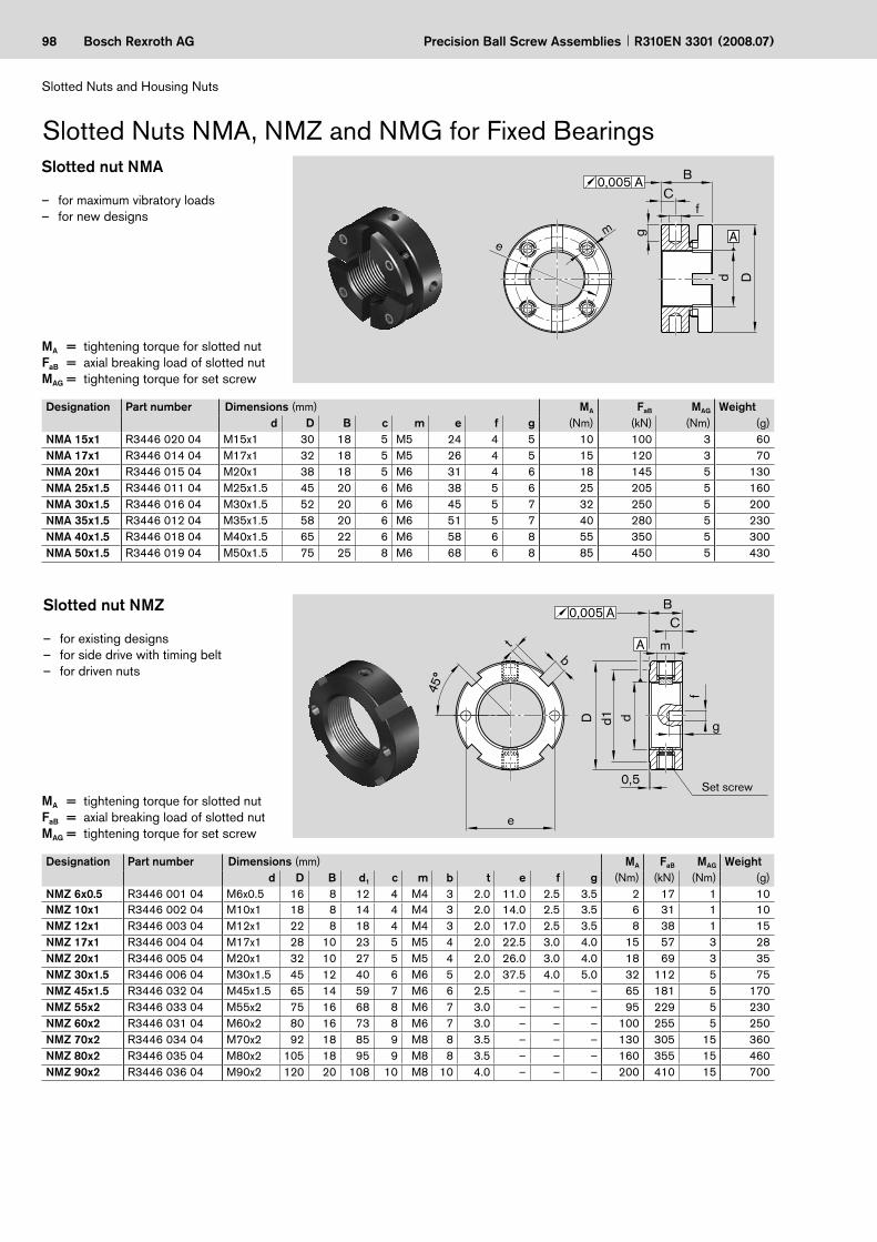
98 Bosch Rexroth AG
A
B
fC
em g
d D
0,005 A
4 5°
d d1
D
0, 5
g
f
m
C B
A
0,005 A
e
t b
Precision Ball Screw Assemblies R310EN 3301 (2008.07)
Slotted Nuts and Housing Nuts
Slotted Nuts NMA, NMZ and NMG for Fixed BearingsSlotted nut NMA
for maximum vibratory loadsfor new designs
––
MA = tightening torque for slotted nutFaB = axial breaking load of slotted nutMAG = tightening torque for set screw
Slotted nut NMZ
for existing designsfor side drive with timing beltfor driven nuts
–––
MA = tightening torque for slotted nutFaB = axial breaking load of slotted nutMAG = tightening torque for set screw
Set screw
Designation Part number Dimensions (mm) MA FaB MAG Weightd D B c m e f g (Nm) (kN) (Nm) (g)
NMA 15x1 R3446 020 04 M15x1 30 18 5 M5 24 4 5 10 100 3 60NMA 17x1 R3446 014 04 M17x1 32 18 5 M5 26 4 5 15 120 3 70NMA 20x1 R3446 015 04 M20x1 38 18 5 M6 31 4 6 18 145 5 130NMA 25x1.5 R3446 011 04 M25x1.5 45 20 6 M6 38 5 6 25 205 5 160NMA 30x1.5 R3446 016 04 M30x1.5 52 20 6 M6 45 5 7 32 250 5 200NMA 35x1.5 R3446 012 04 M35x1.5 58 20 6 M6 51 5 7 40 280 5 230NMA 40x1.5 R3446 018 04 M40x1.5 65 22 6 M6 58 6 8 55 350 5 300NMA 50x1.5 R3446 019 04 M50x1.5 75 25 8 M6 68 6 8 85 450 5 430
Designation Part number Dimensions (mm) MA FaB MAG Weightd D B d1 c m b t e f g (Nm) (kN) (Nm) (g)
NMZ 6x0.5 R3446 001 04 M6x0.5 16 8 12 4 M4 3 2.0 11.0 2.5 3.5 2 17 1 10NMZ 10x1 R3446 002 04 M10x1 18 8 14 4 M4 3 2.0 14.0 2.5 3.5 6 31 1 10NMZ 12x1 R3446 003 04 M12x1 22 8 18 4 M4 3 2.0 17.0 2.5 3.5 8 38 1 15NMZ 17x1 R3446 004 04 M17x1 28 10 23 5 M5 4 2.0 22.5 3.0 4.0 15 57 3 28NMZ 20x1 R3446 005 04 M20x1 32 10 27 5 M5 4 2.0 26.0 3.0 4.0 18 69 3 35NMZ 30x1.5 R3446 006 04 M30x1.5 45 12 40 6 M6 5 2.0 37.5 4.0 5.0 32 112 5 75NMZ 45x1.5 R3446 032 04 M45x1.5 65 14 59 7 M6 6 2.5 – – – 65 181 5 170NMZ 55x2 R3446 033 04 M55x2 75 16 68 8 M6 7 3.0 – – – 95 229 5 230NMZ 60x2 R3446 031 04 M60x2 80 16 73 8 M6 7 3.0 – – – 100 255 5 250NMZ 70x2 R3446 034 04 M70x2 92 18 85 9 M8 8 3.5 – – – 130 305 15 360NMZ 80x2 R3446 035 04 M80x2 105 18 95 9 M8 8 3.5 – – – 160 355 15 460NMZ 90x2 R3446 036 04 M90x2 120 20 108 10 M8 10 4.0 – – – 200 410 15 700
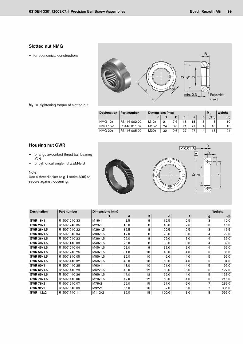
99Bosch Rexroth AG
dd 1D
min. 0,3
B
ba
ef
gB
A0,01 A
D d
Precision Ball Screw AssembliesR310EN 3301 (2008.07)
Housing nut GWR
for angular-contact thrust ball bearing LGNfor cylindrical single nut ZEM-E-S
–
–
Note:Use a threadlocker (e.g. Loctite 638) to secure against loosening.
Slotted nut NMG
for economical constructions–
MA = tightening torque of slotted nut
Polyamide insert
Designation Part number Dimensions (mm) MA Weightd D B d1 a b (Nm) (g)
NMG 12x1 R3446 002 02 M12x1 21 7.6 18 18 3 8 10NMG 15x1 R3446 011 02 M15x1 24 8.6 21 21 4 10 13NMG 20x1 R3446 005 02 M20x1 32 9.6 27 27 4 18 24
Designation Part number Dimensions (mm) WeightD d B e f g (g)
GWR 18x1 R1507 040 33 M18x1 8.5 8 12.5 2.5 3 10.0GWR 23x1 R1507 240 35 M23x1 13.0 8 18.0 2.5 3 15.0GWR 26x1.5 R1507 240 22 M26x1.5 16.5 8 20.5 2.5 3 16.5GWR 30x1.5 R1507 340 34 M30x1.5 17.0 8 23.0 3.0 4 29.0GWR 36x1.5 R1507 040 23 M36x1.5 22.0 8 29.0 3.0 4 35.0GWR 40x1.5 R1507 140 03 M40x1.5 25.0 8 33.0 3.0 4 39.5GWR 45x1.5 R1507 240 04 M45x1.5 28.0 8 38.0 3.0 4 55.0GWR 50x1.5 R1507 240 25 M50x1.5 31.0 10 40.0 4.0 5 86.0GWR 55x1.5 R1507 340 05 M55x1.5 36.0 10 46.0 4.0 5 96.0GWR 58x1.5 R1507 440 32 M58x1.5 43.0 10 50.0 4.0 5 84.0GWR 60x1 R1507 440 28 M60x1 43.0 10 51.0 4.0 5 97.0GWR 62x1.5 R1507 440 29 M62x1.5 43.0 12 53.0 5.0 6 127.0GWR 65x1.5 R1507 440 26 M65x1.5 47.0 12 55.0 4.0 5 136.0GWR 70x1.5 R1507 440 06 M70x1.5 42.0 12 58.0 4.0 5 216.0GWR 78x2 R1507 540 07 M78x2 52.0 15 67.0 6.0 7 286.0GWR 92x2 R1507 640 09 M92x2 65.0 16 82.0 6.0 7 385.0GWR 112x2 R1507 740 11 M112x2 82.0 18 100.0 8.0 8 596.0

100 Bosch Rexroth AG
100
90
80
70
60
50
40
30
20
10
1 2 8765400
= 0.005
= 0.01
= 0. 2
= 0.3
3 9
Precision Ball Screw Assemblies R310EN 3301 (2008.07)
Technical Data
Technical Notes
Lead angle (°)
Effi
cien
cy (%
)
Acme screw
Precision Ball Screw Assembly
DIN 69 051, Part 1 defines a ball screw as follows:
An assembly comprising a ball screw shaft and a ball nut and which is capable of converting rotary motion into linear motion and vice versa. The rolling elements of the assembly are balls. Advantages over the Acme screw drive
The mechanical efficiency of an Acme screw drive is a maximum 50%, whereas a ball screw can reach a mechanical efficiency of up to 98%.Higher life expectancy due to negli-gible wear during operationLess drive power requiredNo stick-slip effectMore precise positioningHigher travel speedLess heat-up
Due to their high mechanical efficiency, ball screws are in principle not self-locking.
Safety informationWe recommend that a safety nut be installed for particularly critical appli-cations in vertical set-ups. Please ask.
–
–
–––––
cSelection criteria for ball screws
The following factors should be consid-ered when selecting the ball screw for a given application:
degree of accuracy required (lead deviation)in-service load conditionsservice lifecritical speedbuckling loadrigidity/permissible clearance or desired preloadcharacteristic speed (max. permissible linear speed)
The following points should be taken into consideration when selecting a ball screw assembly that is to be both cost-efficient and optimally designed:
The lead is a decisive factor for the load-carrying capacity (depending on the maximum possible ball diameter) and the drive moment.The calculation of the service life should be based on average loads and average speeds, not on maximum values.In order for us to provide you with a customized solution, installation drawings or sketches of the ball nut environment should be enclosed with your inquiry.
–
–––––
–
–
–
–
NoteRadial and eccentric forces relative to the screw must be avoided as they have a negative effect on the life and proper function of the ball screw.
Where special conditions of use are involved, please ask.
c

101Bosch Rexroth AG
400
350
300
250
200
150
100
50
01 2 3 4 5 6
32 25 20 16
12
10
5
2,5
40
Precision Ball Screw AssembliesR310EN 3301 (2008.07)
Load-carrying capacities and service lifeWe calculate load-carrying capacities and service life in accordance with DIN 69 051, Part 4 and ISO 3408-4 (P5).
Basic static load rating C0
The static load rating is an axial, concen-trically acting force that induces a per-manent deformation of 0.0001 x the ball diameter between the ball and the ball raceway.
Basic dynamic load rating CThe dynamic load rating is an axial, concentrically acting force of constant magnitude and direction under which 90% of a sufficiently large amount of identical ball screws can achieve a nomi-nal service life of one million revolutions.
Service lifeThe nominal life is expressed by the number of revolutions (or number of operating hours at constant speed) that will be attained or exceeded by 90% of a representative sample of identical ball screws before the first signs of material fatigue become evident. The nominal life is designated as L or Lh, depending on whether it is specified in revolutions or hours.
Short strokeDuring a short stroke, the ball does not make a real turn. It is therefore impos-sible for an adequate lubricating film to form. This may result in premature wear.In the chart, the minimum required stroke (travel) for a 10% lower load rating is shown as a function of the number of turns and lead of the nut. Hence the most favorable range lies above each curve. It may help to have occasional longer strokes, which are performed with simultaneous relubrication as “lubricating strokes”. If in doubt, please ask.
Critical speed and buckling loadThe critical speed and buckling load can be checked using the corresponding charts.For precise calculations see formula 12 15 , in “Design Calculations”
Characteristic speed d0 · nRexroth ball screws can be operated at very high speeds due to their internal ball recirculation system. Characteristic speeds of up to 150,000 are possible depending on the nut type.d0 · n ≤ 150,000 d0 · n ≤ 80,000 (in the case of the ECO series) d0 = nominal diameter (mm) n = speed (min–1)The theoretically possible maximum linear speed v max (m/min) is specified on the page featuring the relevant nut. Actually attainable speeds are heavily dependent among other factors on preload and duty cycle. They are gen-erally restricted by the critical speed. (See “Design Calculations”)
Material, hardnessOur standard ball screw assemblies are made of high-quality, heat-treatable steel, carbon chrome alloy steels or case-hardened steels. The screw and nut raceways have a minimum Rockwell hardness of HRC 60. Ball screw assem-blies made of corrosion-resistant steel (DIN EN ISO 683-17) are also available upon request. Unless otherwise speci-fied, the screw ends are not hardened.
SealingBall screws are precision assemblies that require protection against conta-mination. Flat protective covers and bellows type dust boots or the drive
Short stroke limit (load rating reduced by less than 10%)
Str
oke
(tra
vel)
(mm
)
Number of ball track turns in the nut i
Lead
Permissible operating temperatures:–10°C ≤ Toperating ≤ 80°C
Permissible bearing temperature:–15°C ≤ Tbearing ≤ 80°C
unit AGK are particularly suitable for this purpose. As there are many appli-cations in which these methods do not provide sufficient protection, we have developed a gapless lip-type seal which ensures an optimal sealing effect and maintains high efficiency due to the low friction level. Our ball screws are there-fore supplied with seals in their standard versions. At the customer’s request, these seals can be omitted or special seals used in their place. A reinforced version of the standard seal has been developed for those applications where heavy contamination of the screw ap-pears inevitable. The sealing effect has been improved further by increasing the preload. What must be borne in mind is the significantly higher friction torque in comparison with the standard friction torque (see Technical Data) and the associated increased heat build-up. The reinforced seal can be easily recognized externally by its dark green color.
Permissible operating temperaturesBall screws are suitable for continu-ous operation at temperatures up to 80°C with temporary peaks of 100°C (measurements taken on the outer shell of the nut).

102 Bosch Rexroth AG
l 1
l ul'e
e'p
e'p
ν 300
p
300
+
–
0∆l
l'e
l 0
c = 0
2πrad
2πp
ν'
T
Precision Ball Screw Assemblies R310EN 3301 (2008.07)
Technical Data
Acceptance Conditions and Tolerance GradesPermissible travel deviationin accordance with DIN 69 051, Part 3 and ISO 3408-3Many values are significantly more accurate than those defined in DIN 69 051, Part 3 and ISO 3408-3.
For precision screws SN-R the follow-ing values apply in all cases:
lu e'p (mm)Tolerance grade
> ≤ 5 7 90 100 18 44 110
100 200 20 48 130200 315 23 52 150315
νe'p 300lu
300p
Symbol definitions (excerpt):l0 = nominal travell1 = thread length∆l0 = travel deviationlu = useful travell'e = excess travel (the closer toler-
ances for travel and hardness do not apply here)
c = travel compensation (target travel deviation) (standard: c = 0)
e'p = tolerance mean actual travel deviation
ν300p = permissible travel deviation within 300 mm travel
ν'2πp = permissible travel deviation within one revolution
Improved valuescompared with DIN 69 051, Part 3 and ISO 3408-3 (tolerance reduced by half)
ν300p (mm)Tolerance grade
5 7 923 52 130
ν'2pp (mm)Tolerance grade
5 7 98 10 10
Ball screw with precision-rolled screw SN-R
d0 l'e(mm) (mm)
8 1512, 16 20
20, 25, 32, 40 4050, 63, 80 50
Non-usable length l'e(Excess travel)

103Bosch Rexroth AGPrecision Ball Screw AssembliesR310EN 3301 (2008.07)
Minimum number of measurements within 300 mm (measuring interval) and excess travel to be taken into consideration
Lead P Minimum number of measurements for tolerance grade(mm) 5 7 9
2.5 10 5 55 6 3 3
10 3 1 116 3 1 120 3 1 125 3 1 132 2 1 140 1 1 1

104 Bosch Rexroth AG
5l 5l 5l
2 d0
d 0
2 d0
l 1
5l 5l
5pt
5 m
axt
A A
AA't5p
A A'
d0
2 d0
AA't6p
A A'
l6
d0
l 7
Ct7p'
C
Precision Ball Screw Assemblies R310EN 3301 (2008.07)
Technical Data
Acceptance Conditions and Tolerance GradesRun-outs and location deviations based on DIN 69 051, Part 3 and ISO 3408-3
Radial run-out t5 of the outer diameter of the ball screw shaft over the length l5 used to determine the straightness in relation to AA'.
Coaxial deviation t7' of the journal diam-eter of the ball screw shaft in relation to the bearing diameter for l7 ≤ l.
Radial run-out t6 of the bearing diameter in relation to AA' for l6 ≤ l.Table value t6p applies when I6 ≤ refer-ence length I.
Table value t7p applies when I7 ≤ refer-ence length I.
Bearing seat
Where l6 > l then
Where l7 > l then
d0 l5 t5p in µm for l5for tolerance grade
above up to 5 7; 9= 6 12 80 32 4012 25 16025 50 31550 100 630
100 200 1250
l1/d0 t5max in µmfor l1 ≥ 4l5for tolerance grade
above up to 5 7; 940 64 80
40 60 96 12060 80 160 20080 100 256 320
Nominal diameter d0
Refer-ence length l
t6p in µmfor l6 ≤ l for tolerance grade
above up to 5; 7; 9= 6 20 80 2020 50 125 2550 125 200 25
125 200 315 25
Nominal diameter d0
Refer-ence lengthl
t7p' in µmfor l7 ≤ l for tolerance grade
above up to 5; 7; 9= 6 20 80 620 50 125 650 125 200 7
125 200 315 12
t6a 6p≤ t l6al
t7a 7p≤ t l7al
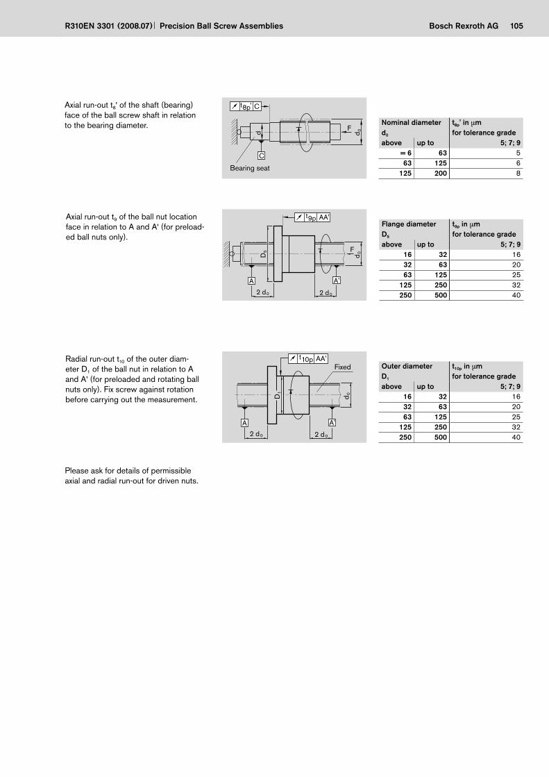
105Bosch Rexroth AG
d0F
d
C
Ct8p'
2 d0
F 0d
5D
2 d0
AA't9p
A A'
2 d0
0d
1D
2 d0
AA't10p
A A'
Precision Ball Screw AssembliesR310EN 3301 (2008.07)
Axial run-out t8' of the shaft (bearing) face of the ball screw shaft in relation to the bearing diameter.
Axial run-out t9 of the ball nut location face in relation to A and A' (for preload-ed ball nuts only).
Bearing seat
Radial run-out t10 of the outer diam- eter D1 of the ball nut in relation to A and A' (for preloaded and rotating ball nuts only). Fix screw against rotation before carrying out the measurement.
Please ask for details of permissible axial and radial run-out for driven nuts.
Fixed
Nominal diameterd0
t8p' in µm for tolerance grade
above up to 5; 7; 9= 6 63 563 125 6
125 200 8
Flange diameterD5
t9p in µm for tolerance grade
above up to 5; 7; 916 32 1632 63 2063 125 25
125 250 32250 500 40
Outer diameterD1
t10p in µm for tolerance grade
above up to 5; 7; 916 32 1632 63 2063 125 25
125 250 32250 500 40

106 Bosch Rexroth AG Precision Ball Screw Assemblies R310EN 3301 (2008.07)
Technical Data
Preload and Rigidity
The rigidity of these types of Rexroth nut systems is approximately the same.This is because the adjustable-preload single nut and the preloaded single nut have a much more compact design and are thus only half as long as a double nut system. The screw is typically far less rigid than the nut unit (for details see “Overall axial rigidity...”).
In addition to single nuts with reduced backlash, Rexroth supplies preloaded or adjustable-preload nut systems.
Adjustable-preload single nutThe adjustable-preload single nut allows cost-efficient design techniques to be implemented in a large number of appli-cations. The radial clearance and preload are adjusted radially via a slot approx. 0.1 mm wide, see section “Mounting”.Depending on the application, we will preload the nut system to 2% or 5% of the basic dynamic load rating. The maximum preload equals approx. 5% of the basic dynamic load rating.
Preloaded single nutSingle nuts can be preloaded to 2% or 5% of the basic dynamic load rating by means of optimized ball size selection.
Double nutTensioning two nuts against each other eliminates the inherent backlash of the ball screw, increases rigidity and thus improves positioning accuracy.As excessive preload can cause a reduc-tion in service life, we recommend that it not be more than 1/3 of the average operating load. Depending on the appli-cation, we will preload the nut system to 7% or 10% of the basic dynamic load rating.
Nut system preload
Driven nutLike the single nut, the driven nut from the “Drive Units” catalog R310EN 3304 can be preloaded to 2%, 3% or 5% of the basic dynamic load rating by means of ball size selection.
Axi
al m
ovem
ent (
defle
ctio
n)
Axial load
Single nut with backlash
Preloaded and adjustable-
preload nut systems
2-start single nut with flangeThe 2-start single nut with flange can be optimally preloaded to 2% or 5% of the dynamic load rating by means of ball size selection.

107Bosch Rexroth AG
Dwd 0d 1d 2
SS2 ≤2
17
18
19
16
Precision Ball Screw AssembliesR310EN 3301 (2008.07)
Overall rigidity
The rigidity of a ball screw is also influ-enced by all adjoining parts such as bearings, housing bores, nut housings etc.
Overall axial rigidity Rbs of the ball screwThe overall axial rigidity Rbs is comprised of the component rigidity of the bearing Rfb, the screw RS and the nut unit Rnu .
Note:Please note that in most cases the rigidity RS of the screw will be signifi-cantly lower than the rigidity Rnu of the nut unit. In an assembly with a diameter of 40 x 10, for example, the rigidity Rnu of the nut unit is 2 to 3 times higher than the rigidity RS of a screw with a length of 500 mm.
Rigidity of the bearing RfbThe rigidity of the bearings corresponds to the values found in the bearing manu-facturer’s catalog. See the corresponding tables in this catalog for rigidity values of the bearings offered by Rexroth.
Rigidity in the area of the nut unit RnuThe rigidity in the area of the nut unit is calculated according per DIN 69 051 (P5).See the corresponding tables for rigidity values.
RS1 = rigidity of the screw (N/mm)d0 = nominal diameter (mm)DW = ball diameter (mm)lS1 = distance between
bearing and nut (mm)
The lowest screw rigidity RS2min occurs at the center of the screw (lS2 = lS/2) and thus equals:
lS
lS2
RS2 = rigidity of the screw (N/mm)d0 = nominal diameter (mm)DW = ball diameter (mm)lS = distance between
bearing and bearing (mm)lS2 = distance between
bearing and nut (mm)
lS1
Ball screw shaft is fixed at one end.1�
Rigidity of the screw RSThe rigidity of the screw RS depends on the type of bearing used.See the corresponding tables for rigidity values.
Ball screw shaft is fixed at both ends.2�
R 165 (d -0.71· D )w02
SS2 S S2S2
(N/µm)
(N/µm)S
660RS2min
(d - 0.71 D )0 w 2
R 165 (d -0.71· D )w02
S1S1 (N/µm)
= + +1Rbs
1Rfb
1RS
1Rnu

108 Bosch Rexroth AG Precision Ball Screw Assemblies R310EN 3301 (2008.07)
Technical Data
Preload and Overall Rigidity of Single Nuts Dynamic drag torque, preload and rigidity for screws of tolerance grade 5-7 with single nuts from diameter 16 mm (smaller diam- eters without backlash only)FSZ-E-S, FEP-E-S (2% only),FEM-E-S, FEM-E-C, ZEM-E-S; SEM-E-S and SEM-E-C (consider centering diameter D1 to be set)(ZEV-E-S and FBZ-E-S with backlash only!)
T0 = overall dynamic drag torqueT0 = Tpr0 + TRD C = basic dynamic load ratingC0 = basic static load ratingTRD = dynamic drag torque of 2 sealsRS = rigidity of the screwRnu = rigidity of the nutTpr0 = dynamic drag torque without
a seald0 = nominal diameterP = leadDw = ball diameteri = number of ball track turns
The values given for dynamic drag torque are proven practical indicators for the nut preloading.
Note:Measurement of the dynamic load torque, see “Mounting.”
Size Load ratings Backlash of single nut Overall rigidity of the screw
dyn. C stat. C0 Standard Reduced RS(N) (N) N·m
µm( )D0 x P x DW - i6 x 1R x 0.8 - 4 900 1290 0.01 0.000 56 x 2R x 0.8 - 4 890 1280 0.01 0.000 58 x 1R x 0.8 - 4 1020 1740 0.01 0.000 98 x 2R x 1.2 - 4 1870 2760 0.01 0.000 98 x 2.5R x 1.588 - 3 2200 2800 0.02 0.010 812 x 2R x 1.2 - 4 2240 4160 0.01 0.000 2112 x 5R x 2 - 3 3800 5800 0.02 0.010 1812 x 10R x 2 - 2 2500 3600 0.02 0.010 1816 x 5R x 3 - 4 12300 16100 0.04 0.020 3216 x 10R x 3 - 3 9600 12300 0.04 0.020 3216 x 16R x 3 - 2 6300 7600 0.04 0.020 3216 x 16R x 3 - 3 9300 12000 0.04 0.020 3220 x 5R/L x 3 - 4 14300 21500 0.04 0.020 5320 x 5R x 3 - 5 17500 27300 0.04 0.020 5320 x 10R x 3 - 4 14100 21300 0.04 0.020 5320 x 20R/L x 3.5 - 2 9100 12100 0.04 0.020 5220 x 20R x 3.5 - 3 13300 18800 0.04 0.020 5220 x 40R x 3.5 - 1x4 14000 26200 0.04 0.020 5225 x 5R/L x 3 - 4 15900 27200 0.04 0.020 8625 x 10R x 3 - 4 15700 27000 0.04 0.020 8625 x 25R/L 3.5 - 2 10100 15100 0.04 0.020 8425 x 25R x 3.5 - 3 14700 23300 0.04 0.020 8425 x 25R x 3.5 -1.2x4 19700 39400 0.04 0.020 8432 x 5R/L x 3.5 - 4 21600 40000 0.04 0.020 14432 x 10R x 3.969 - 5 31700 58300 0.04 0.020 14132 x 20R x 3.969 - 2 13500 21800 0.04 0.020 14132 x 20R x 3.969 - 3 19700 33700 0.04 0.020 14132 x 32R x 3.969 - 2 13400 22000 0.04 0.020 14132 x 32R x 3.969 - 3 19500 34000 0.04 0.020 14132 x 32R x 3.969 -1.2 x 4 26300 57600 0.04 0.020 14140 x 5R/L x 3.5 - 5 29100 64100 0.04 0.020 23240 x 10R/L x 6 - 4 50000 86400 0.07 0.035 21140 x 10R x 6 - 6 72100 132200 0.07 0.035 21140 x 12R x 6 - 4 49900 86200 0.07 0.035 21140 x 16R x 6 - 4 49700 85900 0.07 0.035 21140 x 20R x 6 - 3 37900 62800 0.07 0.035 21140 x 20R x 6 - 8 x 2 76400 171100 0.07 0.035 21140 x 40R x 6 - 2 25500 40300 0.07 0.035 21140 x 40R x 6 - 3 37000 62300 0.07 0.035 21140 x 40R x 6 - 6 x 2 57200 124500 0.07 0.035 21150 x 5R x 3.5 - 5 32000 81300 0.04 0.020 37350 x 10R x 6 - 4 55400 109000 0.07 0.035 34550 x 10R x 6 - 6 79700 166500 0.07 0.035 34550 x 12R x 6 - 6 79600 166400 0.07 0.035 34550 x 16R x 6 - 6 79400 166000 0.07 0.035 34550 x 20R x 6.5 - 3 47900 87900 0.07 0.035 34050 x 20R x 6.5 - 5 75700 149700 0.07 0.035 34050 x 20R x 6.5 - 8 x 2 93200 228000 0.07 0.035 34050 x 25R x 6.5 - 6 x 2 74100 175100 0.07 0.035 34050 x 40R x 6.5 - 2 32100 55800 0.07 0.035 34050 x 40R x 6.5 - 6 x 2 71400 171500 0.07 0.035 34050 x 40R x 6.5 - 3 46500 85900 0.07 0.035 34063 x 10R x 6 - 4 61800 140500 0.07 0.035 56963 x 10R x 6 - 6 88800 214300 0.07 0.035 56963 x 20R x 6.5 - 3 53200 112100 0.07 0.035 56363 x 20R x 6.5 - 5 83900 190300 0.07 0.035 56363 x 20R x 6.5 - 8 x 2 104600 292000 0.07 0.035 56363 x 40R x 6.5 - 2 36900 74300 0.07 0.035 56363 x 40R x 6.5 - 3 53400 114100 0.07 0.035 56363 x 40R x 6.5 - 6 x 2 80000 217000 0.07 0.035 56380 x 10R x 6.5 - 6 108400 291700 0.07 0.035 93880 x 20R x 12.7 - 6 262700 534200 0.11 0.055 832

109Bosch Rexroth AGPrecision Ball Screw AssembliesR310EN 3301 (2008.07)
Size Screws with single nuts2% preload 3% preload 5% preload
Rnu Tpr0 Rnu Tpr0 Rnu Tpr0(N/mm) (Nm) (N/mm) (Nm) (N/mm) (Nm)
Tolerance grade 5; 7 Tolerance grade 5; 7 Tolerance grade 5 Tolerance grade 7D0 x P x DW - i max. max. min. max. min. max. min. max.6 x 1R x 0.8 - 4 – – – – – – – – – –6 x 2R x 0.8 - 4 – – – – – – – – – –8 x 1R x 0.8 - 4 – – – – – – – – – –8 x 2R x 1.2 - 4 – – – – – – – – – –8 x 2.5R x 1.588 - 3 70 0.004 – – – – – – – –12 x 2R x 1.2 - 4 110 0.005 – – – – – – – –12 x 5R x 2 - 3 100 0.009 – – – – – – – –12 x 10R x 2 - 2 60 0.006 – – – – – – – –16 x 5R x 3 - 4 210 0.040 240 0.020 0.10 280 0.05 0.15 0.04 0.1616 x 10R x 3 - 3 160 0.030 190 0.010 0.08 220 0.04 0.12 0.03 0.1216 x 16R x 3 - 2 100 0.020 120 0.005 0.06 140 0.03 0.08 0.02 0.0816 x 16R x 3 - 3 160 0.030 180 0.010 0.08 210 0.04 0.11 0.03 0.1220 x 5R/L x 3 - 4 260 0.060 300 0.030 0.14 350 0.07 0.21 0.06 0.2320 x 5R x 3 - 5 330 0.070 375 0.040 0.17 440 0.09 0.26 0.07 0.2820 x 10R x 3 - 4 260 0.060 300 0.030 0.14 350 0.07 0.21 0.06 0.2320 x 20R/L x 3.5 - 2 130 0.040 150 0.020 0.09 180 0.05 0.14 0.04 0.1520 x 20R x 3.5 - 3 200 0.050 220 0.030 0.13 270 0.07 0.20 0.05 0.2120 x 40R x 3.5 - 1 x 4 215 0.060 – – – – – – – –25 x 5R/L x 3 - 4 310 0.080 350 0.040 0.2 410 0.10 0.30 0.08 0.3225 x 10R x 3 - 4 320 0.080 360 0.040 0.19 430 0.10 0.29 0.08 0.3125 x 25R/L x 3.5 - 2 160 0.050 180 0.030 0.12 210 0.06 0.19 0.05 0.2025 x 25R x 3.5 - 3 240 0.070 270 0.040 0.18 320 0.09 0.28 0.07 0.2925 x 25R x 3.5 -1.2 x 4 350 0.100 – – – – – – – –32 x 5R/L x 3.5 - 4 380 0.140 420 0.100 0.31 500 0.24 0.45 0.21 0.4832 x 10R x 3.969 - 5 500 0.200 570 0.150 0.46 670 0.36 0.66 0.30 0.7132 x 20R x 3.969 - 2 200 0.090 230 0.050 0.21 270 0.15 0.28 0.13 0.3032 x 20R x 3.969 - 3 300 0.130 340 0.070 0.31 410 0.22 0.41 0.19 0.4432 x 32R x 3.969 - 2 200 0.090 220 0.050 0.21 260 0.15 0.28 0.13 0.3032 x 32R x 3.969 - 3 300 0.120 340 0.070 0.31 400 0.22 0.41 0.19 0.4432 x 32R x 3.969 -1.2 x 4 440 0.170 – – – – – – – –40 x 5R/L x 3.5 - 5 550 0.230 620 0.170 0.52 720 0.41 0.76 0.35 0.8140 x 10R/L x 6 - 4 500 0.400 570 0.360 0.84 670 0.75 1.25 0.70 1.3040 x 10R x 6 - 6 760 0.580 860 0.520 1.21 1010 1.08 1.80 1.01 1.8740 x 12R x 6 - 4 510 0.400 580 0.300 0.90 680 0.75 1.25 0.70 1.3040 x 16R x 6 - 4 510 0.400 580 0.300 0.89 680 0.75 1.24 0.70 1.2940 x 20R x 6 - 3 380 0.300 430 0.230 0.68 510 0.57 0.95 0.53 0.9940 x 20R x 6 - 8 x 2 – – 1005 0.55 1.28 – – – – –40 x 40R x 6 - 2 240 0.200 280 0.150 0.46 330 0.36 0.66 0.31 0.7140 x 40R x 6 - 3 370 0.300 420 0.220 0.67 490 0.56 0.93 0.52 0.9640 x 40R x 6 - 6 x 2 – – 723 0.41 0.96 – – – – –50 x 5R x 3.5 - 5 640 0.320 720 0.240 0.72 830 0.60 1.00 0.56 1.0450 x 10R x 6 - 4 590 0.550 670 0.500 1.16 780 1.04 1.73 0.97 1.8050 x 10R x 6 - 6 890 0.800 1000 0.720 1.67 1180 1.49 2.49 1.39 2.5950 x 12R x 6 - 6 900 0.800 1020 0.720 1.67 1190 1.49 2.49 1.39 2.5950 x 16R x 6 - 6 910 0.790 1030 0.710 1.67 1210 1.49 2.48 1.39 2.5850 x 20R x 6.5 - 3 470 0.480 540 0.430 1.01 630 0.90 1.50 0.84 1.5650 x 20R x 6.5 - 5 780 0.760 880 0.680 1.59 1050 1.42 2.37 1.32 2.4650 x 20R x 6.5 - 8 x 2 – – 1192 0.84 1.96 – – – – –50 x 25R x 6.5 - 6 x 2 – – 928 0.67 1.56 – – – – –50 x 40R x 6.5 - 2 300 0.320 340 0.240 0.72 410 0.60 1.00 0.56 1.0450 x 40R x 6.5 - 3 450 0.470 520 0.420 0.98 610 0.87 1.45 0.81 1.5150 x 40R x 6.5 - 6 x 2 – 900 0.64 1.50 – – – – –63 x 10R x 6 - 4 700 0.780 790 0.700 1.64 920 1.46 2.43 1.36 2.5363 x 10R x 6 - 6 1050 1.120 1190 1.010 2.35 1380 2.24 3.36 2.10 3.5063 x 20R x 6.5 - 3 560 0.670 640 0.600 1.41 750 1.26 2.09 1.17 2.1863 x 20R x 6.5 - 5 930 1.060 1060 0.950 2.22 1250 2.11 3.17 1.98 3.3063 x 20R x 6.5 - 8 x 2 – – 1448 1.19 2.77 – – – – –63 x 40R x 6.5 - 2 380 0.460 440 0.420 0.98 510 0.87 1.45 0.81 1.5163 x 40R x 6.5 - 3 570 0.670 660 0.610 1.41 770 1.26 2.10 1.18 2.1963 x 40R x 6.5 -6 x 2 – – 1095 0.91 2.12 – – – – –80 x 10R x 6.5 - 6 1240 1.730 1390 1.820 3.38 1610 3.47 5.20 3.25 5.4280 x 20R x 12.7 - 6 1400 4.200 1590 4.410 8.20 1870 8.41 12.61 7.88 13.14

110 Bosch Rexroth AG Precision Ball Screw Assemblies R310EN 3301 (2008.07)
Technical Data
Preload and Rigidity of Double NutsDynamic drag torque, preload and rigidity for screws of tolerance grade 5-7 with double nuts FDM-E-S, FDM-E-C
T0 = overall dynamic drag torqueT0 = Tpr0 + TRD C = basic dynamic load ratingC0 = basic static load ratingTRD = dynamic drag torque of 2 sealsRS = rigidity of the screwRnu = rigidity of the nutTpr0 = dynamic drag torque without
a seald0 = nominal diameterP = leadDw = ball diameteri = number of ball track turns
The values given for dynamic drag torque are proven practical indicators for the nut preloading.
Note:Measurement of the dynamic load torque, see “Mounting.”
SizeLoad ratings Rigidity of the screw
RS
dyn. C stat. C0 N·mµm( )D0 x P x DW - i (N) (N)
16 x 5R x 3 - 4 12300 16100 3220 x 5R x 3 - 4 14300 21500 5325 x 5R x 3 - 4 15900 27200 8625 x 10R x 3 - 4 15700 27000 8632 x 5R x 3.5 - 4 21600 40000 14432 x 10R x 3.969 - 5 31700 58300 14140 x 5R x 3.5 - 5 29100 64100 23240 x 10R x 6 - 4 50000 86400 21140 x 10R x 6 - 6 72100 132200 21140 x 20R x 6 - 3 37900 62800 21150 x 5R x 3.5 - 5 32000 81300 37350 x 10R x 6 - 4 55400 109000 34550 x 10R x 6 - 6 79700 166500 34550 x 20R x 6.5 - 5 75700 149700 34063 x 10R x 6 - 4 61800 140500 56963 x 10R x 6 - 6 88800 214300 56963 x 20R x 6.5 - 5 83900 190300 56380 x 10R x 6.5 - 6 108400 291700 93880 x 20R x 12.7 - 6 262700 534200 832

111Bosch Rexroth AGPrecision Ball Screw AssembliesR310EN 3301 (2008.07)
Size Screws with double nuts FDM-E-S, FDM-E-C
Rnu
(N/mm)
7% preload 10% preload Tpr0 Rnu Tpr0
(Nm) (N/mm) (Nm)Tolerance grade 5 Tolerance grade 7 Tolerance grade 5 Tolerance grade 7
D0 x P x DW - i min. max. min. max. min. max. min. max.16 x 5R x 3 - 4 310 0.03 0.08 0.02 0.09 350 0.04 0.12 0.03 0.1320 x 5R x 3 - 4 390 0.04 0.12 0.03 0.13 430 0.06 0.17 0.05 0.1825 x 5R x 3 - 4 460 0.06 0.17 0.04 0.18 510 0.08 0.24 0.06 0.2525 x 10R x 3 - 4 470 0.05 0.16 0.04 0.18 530 0.08 0.24 0.06 0.2532 x 5R x 3.5 - 4 550 0.10 0.29 0.08 0.31 610 0.19 0.36 0.17 0.3932 x 10R x 3.969 750 0.20 0.37 0.17 0.40 830 0.28 0.53 0.24 0.5740 x 5R x 3.5 - 5 790 0.23 0.42 0.20 0.46 870 0.33 0.61 0.28 0.6540 x 10R x 6 - 4 740 0.39 0.73 0.34 0.78 830 0.60 1.00 0.56 1.0440 x 10R x 6 - 6 1120 0.61 1.01 0.57 1.05 1250 0.87 1.44 0.81 1.5040 x 20R x 6 - 3 570 0.30 0.55 0.25 0.59 630 0.45 0.76 0.42 0.7950 x 5R x 3.5 - 5 920 0.31 0.58 0.27 0.63 1010 0.48 0.80 0.45 0.8350 x 10R x 6 - 4 870 0.58 0.97 0.54 1.01 960 0.83 1.39 0.78 1.4450 x 10R x 6 - 6 1300 0.84 1.39 0.78 1.45 1450 1.20 1.99 1.12 2.0750 x 20R x 6.5 - 5 1170 0.79 1.32 0.74 1.38 1310 1.14 1.89 1.06 1.9763 x 10R x 6 - 4 1020 0.82 1.36 0.76 1.42 1120 1.17 1.95 1.09 2.0263 x 10R x 6 - 6 1520 1.17 1.96 1.10 2.04 1690 1.68 2.80 1.57 2.9163 x 20R x 6.5 - 5 1390 1.11 1.85 1.04 1.92 1560 1.59 2.64 1.48 2.7580 x 10R x 6.5 - 6 1770 1.82 3.04 1.70 3.16 1950 2.78 4.16 2.60 4.3480 x 20R x 12.7 - 6 2070 4.71 7.06 4.41 7.36 2320 6.73 10.09 6.30 10.51
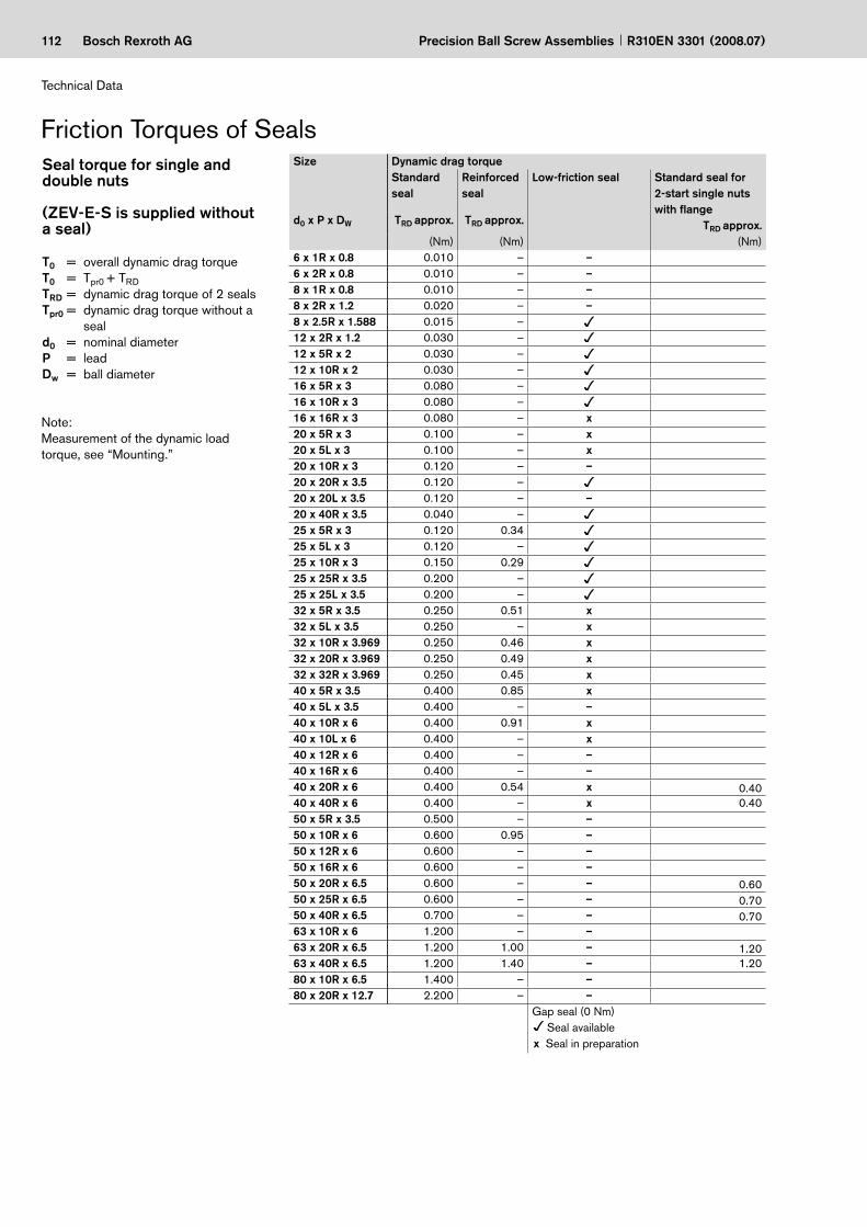
112 Bosch Rexroth AG Precision Ball Screw Assemblies R310EN 3301 (2008.07)
Technical Data
Friction Torques of SealsSeal torque for single and double nuts (ZEV-E-S is supplied without a seal)
T0 = overall dynamic drag torqueT0 = Tpr0 + TRD TRD = dynamic drag torque of 2 sealsTpr0 = dynamic drag torque without a
seald0 = nominal diameterP = leadDw = ball diameter
Note:Measurement of the dynamic load torque, see “Mounting.”
Size Dynamic drag torque Standard seal
Reinforced seal
Low-friction seal Standard seal for 2-start single nuts with flange
TRD approx.d0 x P x DW TRD approx. TRD approx.
(Nm) (Nm) (Nm)6 x 1R x 0.8 0.010 – –6 x 2R x 0.8 0.010 – –8 x 1R x 0.8 0.010 – –8 x 2R x 1.2 0.020 – –8 x 2.5R x 1.588 0.015 –12 x 2R x 1.2 0.030 –12 x 5R x 2 0.030 –12 x 10R x 2 0.030 –16 x 5R x 3 0.080 –16 x 10R x 3 0.080 –16 x 16R x 3 0.080 – x20 x 5R x 3 0.100 – x20 x 5L x 3 0.100 – x20 x 10R x 3 0.120 – –20 x 20R x 3.5 0.120 –20 x 20L x 3.5 0.120 – –20 x 40R x 3.5 0.040 –25 x 5R x 3 0.120 0.3425 x 5L x 3 0.120 –25 x 10R x 3 0.150 0.2925 x 25R x 3.5 0.200 –25 x 25L x 3.5 0.200 –32 x 5R x 3.5 0.250 0.51 x32 x 5L x 3.5 0.250 – x32 x 10R x 3.969 0.250 0.46 x32 x 20R x 3.969 0.250 0.49 x32 x 32R x 3.969 0.250 0.45 x40 x 5R x 3.5 0.400 0.85 x40 x 5L x 3.5 0.400 – –40 x 10R x 6 0.400 0.91 x40 x 10L x 6 0.400 – x40 x 12R x 6 0.400 – –40 x 16R x 6 0.400 – –40 x 20R x 6 0.400 0.54 x 0.4040 x 40R x 6 0.400 – x 0.4050 x 5R x 3.5 0.500 – –50 x 10R x 6 0.600 0.95 –50 x 12R x 6 0.600 – –50 x 16R x 6 0.600 – –50 x 20R x 6.5 0.600 – – 0.6050 x 25R x 6.5 0.600 – – 0.7050 x 40R x 6.5 0.700 – – 0.7063 x 10R x 6 1.200 – –63 x 20R x 6.5 1.200 1.00 – 1.2063 x 40R x 6.5 1.200 1.40 – 1.2080 x 10R x 6.5 1.400 – –80 x 20R x 12.7 2.200 – –
Gap seal (0 Nm) Seal available
x Seal in preparation

113Bosch Rexroth AG
5 - 10 mm
Precision Ball Screw AssembliesR310EN 3301 (2008.07)
Please bear in mind the following when changing or retrofitting the seals:
All precision-rolled screws SN-R with small leads are designed as single-start screws (Fig. 1). There is therefore only one ball track on the screw.
However precision-rolled screws SN-R with higher leads are designed as 2-start or 4-start screws (Figs. 2 and 3). “Reinforced seals” for precision-rolled screws SN-R are available as an option. These are identified by their opal-green color and their part number.
Low-friction seals for precision-rolled screws SN-R are available upon request. This version is currently in preparation. The seals are identified by their red-brown color and their part number.
Inserting the seal
Position the nut on the screw as illus-trated in the diagram. Insert the seal so that its projection is in the recess and press it in until it snaps into the groove. While turning the nut on the screw, watch the sealing lip carefully and straighten it if necessary by apply- ing pressure to the end surface. Ensure that the lip is not damaged.
Detailed mounting instructions are delivered along with the parts.
Standard nuts 2-start nuts
Fig. 1Single-start seal
Fig. 2Seal for 2-start precision-rolled screw SN-R with average lead
Fig. 3Seal for 4-start precision-rolled screw SN-R with high lead

114 Bosch Rexroth AG Precision Ball Screw Assemblies R310EN 3301 (2008.07)
Mounting
Storage
Ball screw assemblies are high-quality systems that must be treated with due care. In order to prevent damage and contamination, the elements should not be removed from the protective wrapping until immediately before installation. Once they have been removed from the packag-ing, they must be set down on V-shaped cradles.
Condition as delivered
Rexroth Ball Screws are normally deliv-ered with an initial supply of grease type Rexroth Dynalub. Relubrication with grease or oil is thus possible, and cartridges and cans of this grease are available. If another lubricant is used, you will need to check that it is compatible with the initial supply.
For special cases, the ball screws can also be supplied with only a preservative coating. This can be indicated by choos-ing the appropriate option number in the ordering code.
ImportantThe selected lubricant must be in the nut before the machine is started.
Cleaning
Various cleaning agents can be used to degrease and wash the assembly:
aqueous cleaning agents organic cleaning agents
ImportantImmediately after cleaning, thoroughly dry all parts, then apply a preservative coating or anti-corrosion oil. In all cases, take care to observe the appropriate legal regulations (environmental protection, health and safety at work, etc.) as well as the specifications for the cleaning agent (e.g. handling).
c
––
c
The nut is to be mounted as follows:Remove the rubber ring from one end of the mounting arbor.
Push the mounting arbor with nut until it bears against the end of the thread. The arbor must make contact with no axial clearance.
Carefully turn the nut unit onto the thread, applying only slight thrust.
The various mounting steps are described below.
Proceed in reverse order when removing the nut from the screw. Take particular care not to damage the nut, screw or internal components, as this could result in the premature failure of the ball screw assembly.
Mounting steps
The nut unit may only be mounted on a screw with machined ends using a mount-ing arbor. In this case, the screw spigot serves to center the mounting arbor. On a screw end form “00”, a centering hole “Z” can be used to fit an auxiliary spigot as a mounting aid. The outer diameter of the arbor should be approx. 0.1 mm smaller than the root diameter of the screw. In most cases, the transport arbor on which the nuts are delivered may be used to mount the nut. The end of the screw thread must be carefully chamfered in order to prevent damage to the seal and the internal components of the nut unit.
Preloaded single nutDouble nut
These models are always supplied with premounted nut units.
The nut unit and screw must not be disassembled. Should this become necessary for any reason, please ask.
Nut mounting
Nut mounting
Single nut with standard backlashSingle nut with reduced backlashAdjustable-preload single nut
Remove the arbor only when the nut unit is fully located on the screw thread.
Mounting

115Bosch Rexroth AG
T = F·r
r
pra
D1
F
Precision Ball Screw AssembliesR310EN 3301 (2008.07)
Installation in the machine
It is not normally necessary to remove the preservative coating before instal-lation.
If the ball screw is contaminated it must first be cleaned (see “Cleaning”) and re-oiledPush the nut unit into the mounting bore, taking care to avoid any impact force or misalignment.Tighten the mounting screws using a torque wrench if necessary. Maximum tightening torque for the steel/steel material pairing (Rm ≥ 370 N/mm2), see table.
–
–
–
Preload of adjustable-preload single nuts
Measurement of the dynamic drag torque for SEM-E-C and SEM-E-S.Using the adjusting screw, reduce the clearance of the nut mounted on the screw until the corresponding dynamic drag torque Tpr0 specified in the table ! page 109, has been attained (ball screw lightly oiled).Check this torque along the entire length of the thread; if the torque deviates from the value specified in the table at any point along the thread, adjust accord-ingly. Once the torque has been properly ad-justed, the centering diameter D1 must correspond to the values specified in the table ! pages 34 and 38. Cover the head of the screw with a protective cap.
Tpra = currently measured dynamic drag torque
Measuring gaugee.g. spring gauge
Adjusting screw
For the steel/aluminum and alumi-num/aluminum material pairings (Rm ≥ 280 N/mm2) the maximum tightening torques specified in the follow table apply. When driving screws into aluminum, the length of thread engagement should be at least 1.5 times the screw diameter.
–
Mounting instructions are supplied as standard along with every unit. Please ask for extra copies if needed.
Alignment of the precision ball screw assembly in the machine
A gauge with a self-aligning contact pad is available from Rexroth for easy alignment of the ball screw assembly.
Two pads of different lengths are avail-able, which can be used depending on the screw lead:
Part number R3305 131 19 Length 33 mm for leads < 20Part number R3305 131 21 Length 50 mm for leads > 20
–
–
Tightening torques for fastening screws according to VDI 2230 for mG = mK = 0.125
Steel/steel material pairingScrew diameter (mm)
Tightening torque (Nm) Strength class per DIN ISO 898:
8.8 10.9 12.9M3 1.3 1.8 2.1M4 2.7 3.8 4.6M5 5.5 8.0 9.5M6 9.5 13.0 16.0M8 23.0 32.0 39.0M10 46.0 64.0 77.0M12 80.0 110.0 135.0M14 125.0 180.0 215.0M16 195.0 275.0 330.0M18 280.0 400.0 470.0M20 390.0 560.0 650.0
Steel/aluminum and aluminum/aluminum material pairingsScrew diameter (mm)
Tightening torque (Nm) Strength class per DIN ISO 898:
8.8 10.9 12.9M3 1.2 1.2 1.2M4 2.4 2.4 2.4M5 4.8 4.8 4.8M6 8.5 8.5 8.5M8 20.0 20.0 20.0M10 41.0 41.0 41.0M12 70.0 70.0 70.0M14 110.0 110.0 110.0M16 175.0 175.0 175.0M18 250.0 250.0 250.0M20 345.0 345.0 345.0

116 Bosch Rexroth AG Precision Ball Screw Assemblies R310EN 3301 (2008.07)
Lubrication
Grease lubricationThe advantage of grease lubrication is that the ball screw can run long distances on one supply of grease. As a result, a lubricating system is not required in many cases. The amount of grease used should fill the nuts to approximately half of their capacity.All commercially available high-quality ball bearing lubricating greases may be used. Read the lubricant manufacturer’s speci-fications carefully! Never use greases with solid lubricant components (e.g. graphite or MoS2).
Oil lubricationThe influence of the temperature on the performance of the ball screw is very sig-nificant, as the thermal expansion of the ball screw interferes with the positioning accuracy of the assembly.One of the advantages of oil lubrication over grease lubrication is therefore the minimized heat build-up of the ball screw, particularly at high speeds.As a rule, commercially available mineral base oils used for ball bearings are suit-able. The necessary viscosity depends on the speed, temperature and load
Standard lubrication practices for ball bearings also apply to ball screws. Lubricant loss is, however, greater than that from conventional ball bearings, for instance, due to the axial motion between the screw and the nut.
Relubrication quantity and intervals for oil
Relubrication intervals for NLGI-2 greases
Limit conditions:Load = ≤ 0.2 Cnmin = 100 min–1
Tempmax. nut = 80 °CTempcontinuous nut = 60 °C
For relubrication, grease cartridges containing Dynalub 510 and 520 are available from Rexroth.Greases in accordance with DIN 51825- K2K and, for higher loads, KP2K of NLGI Class 2 in accordance with DIN 51818 are recommended for the longest pos-sible lubrication intervals. Tests have shown that greases of NLGI Class 00 achieve only about 50% of the running performance of Class 2 at higher loads. The relubrication interval depends on many factors such as the degree of contamination, operating temperature, load, etc. The following values can thus serve only as a guideline.
Orientation: – any Operating mode: – driven screw – no short stroking
or hypercritical operation
Sealing: – standard
d0 Lubricating quantity Lubricating intervalRelubrication Revolutions Travel (km) with lead P =Ve (ml) (mill.) 1 2 2.5 5 10 16 20 25 32 40
≤ 40 see table for NLGI-2 greases
50 50 100 125 250 500 800 1000 1250 1600 2000> 40 10 50 100 160 200 400
d0 = nominal diameter
Lubricationconditions of the respective application (see DIN 51517, 51519 and GfT Work-sheet 3).Oils ranging from ISO VG 68 to approx. ISO VG 460 are used in practice. The high viscosity grades (e.g. ISO VG 460) should be preferred in general and partic-ularly for slow running screws. A maximum relubrication interval of up to 10 operating hours can be attained with small quanti-ties from the adjacent table. Please ask for details for driven nuts.
d0 Lubricating quantity Lubricating interval1)
Initial lubrication Relubrication Time Revolutions Travel (km) with lead P =Ve (ml) Vn (ml/10 h) (h) (mill.) 1 2 2.5 5 10 12 16 20 25 32 40
6 0.300 0.030 10 1.3 1.3 2.68 0.300 0.030 10 1.3 1.3 2.6 3.312 0.300 0.030 10 1.3 2.6 6.5 13.016 0.300 0.030 10 1.3 6.5 13.0 20.820 0.600 0.060 10 1.0 5.0 20.0 40.025 0.600 0.060 10 1.0 5.0 10.0 25.032 0.600 0.060 10 1.0 5.0 10.0 20.0 32.040 2.0002) 0.4002) 10 1.0 5.0 10.0 12.0 16.0 20.0 40.050 4.0002) 0.8002) 10 1.0 5.0 10.0 12.0 16.0 20.0 25.0 40.063 4.0002) 0.8002) 10 1.0 10.0 20.0 40.080 8.000 1.600 10 1.0 10.0 20.0 40.0
d0 = nominal diameterThe value first reached defines the lubricating interval.1) For 2-start single nut FED-E-B: use double the quantity of lubricant2)

117Bosch Rexroth AGPrecision Ball Screw AssembliesR310EN 3301 (2008.07)
Relubrication quantities for Standard series
The nut has to be lubricated with lubri-cant via the lube port before the ball screw is started.
Twice the relubrication quantity of grease is to be used when lubricating for the first time.
Size Relubrication quantity of grease (g)Single nut Double nutFEM-E-C / FEM-E-S / SEM-E-C FDM-E-C / FDM-E-SSEM-E-S / ZEM-E-A / ZEM-E-S / FED-E-BPrecision screw Precision screw
d0 x P x DW - i SN-R SN-R8 x 2.5R x 1.588 - 3 0.10 –
NLGI Class 00Dynalub 520
12 x 2R x 1.2 - 4 0.15 –12 x 5R x 2 - 3 0.30 –12 x 10R x 2 - 2 0.30 –16 x 5R x 3 - 4 0.60 1.7
NLGI Class 2Dynalub 510
16 x 10R x 3 - 3 0.80 –16 x 16R x 3 - 2 0.90 –16 x 16R x 3 - 3 1.10 –20 x 5R/L x 3 - 4 0.90 2.720 x 5R x 3 - 5 1.00 –20 x 10R x 3 - 4 1.40 –20 x 20R/L x 3.5 - 2 1.70 –20 x 20R x 3.5 - 3 2.20 –25 x 5R/L x 3 - 4 1.40 3.225 x 10R x 3 - 4 1.70 3.825 x 25R/L x 3.5 - 2 2.40 –25 x 25R x 3.5 - 3 3.10 –32 x 5L x 3.5 - 4 2.30 –32 x 5R x 3.5 - 4 2.00 4.532 x 10R x 3.969 - 5 2.80 6.032 x 20R x 3.969 - 2 2.50 –32 x 20R x 3.969 - 3 3.20 –32 x 32R x 3.969 - 2 3.70 –32 x 32R x 3.969 - 3 4.90 –40 x 5L x 3.5 - 5 3.10 –40 x 5R x 3.5 - 5 2.70 6.940 x 10L x 6 - 4 6.00 –40 x 10R x 6 - 4 6.00 15.140 x 10R x 6 - 6 7.30 17.740 x 12R x 6 - 4 6.10 –40 x 16R x 6 - 4 8.30 19.340 x 20R x 6 - 3 7.80 18.540 x 20R x 6 - 8 x 2 8.60 –40 x 40R x 6 - 2 9.40 –40 x 40R x 6 - 3 12.90 –40 x 40R x 6 - 6 x 2 13.80 –50 x 5R x 3.5 - 5 3.90 7.150 x 10R x 6 - 4 8.00 19.750 x 10R x 6 - 6 9.70 23.050 x 12R x 6 - 6 10.40 –50 x 16R x 6 - 6 14.60 –50 x 20R x 6.5 - 3 11.40 –50 x 20R x 6.5 - 5 15.60 31.350 x 20R x 6.5 - 8 x 2 9.10 –50 x 25R x 6.5 - 6 x 2 9.60 –50 x 40R x 6.5 - 2 13.90 –50 x 40R x 6.5 - 3 18.60 –50 x 40R x 6.5 - 6 x 2 17.60 –63 x 10R x 6 - 4 9.00 23.063 x 10R x 6 - 6 11.00 27.063 x 20R x 6.5 - 3 13.90 –63 x 20R x 6.5 - 5 19.20 39.463 x 20R x 6.5 - 8 x 2 13.20 –63 x 40R x 6.5 - 2 17.00 –63 x 40R x 6.5 - 3 22.90 –63 x 40R x 6.5 - 6 x 2 24.80 –80 x 10R x 6.5 - 6 16.30 39.080 x 20R x 12.7 - 6 59.00 119.5
For NLGI Class 2 and NLGI Class 00 greases:

118 Bosch Rexroth AG Precision Ball Screw Assemblies R310EN 3301 (2008.07)
Lubrication
For NLGI Class 2 and NLGI Class 00 greases:
The nut has to be lubricated with lubri-cant via the lube port before the ball screw is started.
Twice the relubrication quantity of grease is to be used when lubricating for the first time.
Relubrication quantities for Miniature and ECO series
LubricationSize Relubrication quantity of grease (g)
Single nut, precision-rolled screw SN-Rd0 x P x DW - i FEM-E-B Miniature FSZ-E-S FEP-E-S ZEV-E-S6 x 1R x 0,8- 4 0,06 – – – NLGI Class 00
Dynalub 5206 x 2R x 0,8- 4 0,12 – – –8 x 1R x 0,8 - 4 0,12 – – –8 x 2R x 1,2 - 4 0,24 – – –8 x 2,5R x 1,588 - 3 0,10 – – –12 x 2R x 1,2 - 4 0,15 – – –12 x 5R x 2 - 3 0,30 – – 0,3012 x 10R x 2 - 2 0,30 – – 0,3016 x 5L x 3 - 3 – – – 0,85 NLGI Class 2
Dynalub 51016 x 5R x 3 - 3 – – – 0,8516 x 10R x 3 - 3 – – – 1,0020 x 5R x 3 - 4 – 0,7 – 1,2020 x 5R x 3 - 5 – – – –20 x 40R x 3,5 - 1 x 4 – – 1,6 –25 x 5R x 3 - 4 – 1,1 – –25 x 10R x 3 - 4 – 1,3 – –25 x 25R x 3,5 - 1,2 x 4 – – 1,5 –32 x 5R x 3,5 - 4 – 1,6 – –32 x 10R x 3,969 - 5 – 2,3 – –32 x 20R x 3,969 - 2 – 2,0 – –32 x 32R x 3,969 - 1,2 x 4 – – 2,6 –40 x 5R x 3,5 - 5 – 2,2 – –40 x 10R x 6 - 4 – 5,2 – –40 x 20R x 6 - 3 – 6,7 – –

119Bosch Rexroth AGPrecision Ball Screw AssembliesR310EN 3301 (2008.07)
High-performance lubricant for Linear Motion Systems (not released for the USA)
Product description Dynalub 510 ApplicationsUnder conventional environmental con-ditions this ground-fiber, homogeneous grease is ideally suitable for the lubrica-tion of linear elements:
for loads of up to 0.5 Cdynalso for short-stroke applications ≥ 1 (mm)
––
Technical data Chemical composition Mineral oil, special lithium soap, agentsDesignation KP2K-20 DIN 51 825Appearance Light-brown/beige, ground-fiberService temperature range –20 °C to +80 °CNLGI Class 2Worked penetration 265-295 1/10 mm DIN ISO 2137Water resistance 0-60, 1-90 DIN 51 807 P1Melting point in °C > 165 DIN ISO 2176Flash point in °C > 200 – base oil DIN ISO 2592Basic oil viscosity 100 mm2/s 40 °C DIN 51 562
10 mm2/s 100 °CFlow pressure at –20°C < 1400 hPa DIN 51 805EMCOR test 0/0 DIN 51 802Density at +25°C approx. 0.92 g/cm3 DIN 51 757Copper corrosion 2 (24 h/120 °C) DIN 51 811Four ball tester welding load > 2000 N DIN 51 350 P4Four ball tester impression diameter 0.93 (400 N, 1 h) DIN 51 350 P5Shelf life in original container 2 years
Product description Dynalub 520 ApplicationsUnder conventional environmental con-ditions this ground-fiber, homogeneous grease is ideally suited for the lubrication of miniature linear elements and for use in centralized lubrication systems.
Technical data Chemical composition Mineral oil, special lithium soap, agentsDesignation KP00K-20 DIN 51 825Appearance Light-brown/beige, ground-fiberService temperature range –20 °C to +80 °CNLGI Class 00Worked penetration 400-430 1/10 mm DIN ISO 2137Water resistance 1-90 DIN 51 807 P1Melting point in °C > 160 DIN ISO 2176Flash point in °C > 200 – base oil DIN ISO 2592Basic oil viscosity 100 mm2/s 40 °C DIN 51 562
10 mm2/s 100 °CFlow pressure at –20°C < 700 hPa DIN 51 805EMCOR test 0 DIN 51 802Density at +25°C approx. 0.92 g/cm3 DIN 51 757Copper corrosion 0-1 (24 h/100 °C) DIN 51 811Four ball tester welding load 1800 N DIN 51 350 P4Four ball tester impression diameter 0.80 (400 N, 1 h) DIN 51 350 P5Shelf life in original container 2 years
For further details, see “Safety Data Sheet Dynalub 510”R310EN 2052 (2004.04)
For further details, see “Safety Data Sheet Dynalub 520” R310EN 2053 (2004.04)
Dynalub 510 is an NLGI Class 2 lithium-based high-performance grease specially developed for linear motion systems. It is notable for offering excel-lent water resistance and protection against corrosion, and is suited for use at temperatures of between –20 °C and 80 °C.
Dynalub 520 is an NLGI Class 00 lithium-based high-performance grease specially developed for linear motion systems. It is notable for offering excel-lent water resistance and protection against corrosion, and is suited for use at temperatures of between –20 °C and +80 °C.

120 Bosch Rexroth AG
nm =|n1| · qt1 + |n2| · qt2 + ... + |nn| · qtn
100%
F > 2,8 Xpr · C Feff n = |Fn|
F ≤ 2,8 Xpr · C|Fn|
2,8 · Xpr · CFeff n = + 1 · Xpr · C
32
Fm = Feff 1 · + Feff 2 · + ... + Feff n ·qt1100%
3 3 3 qt2100%
3 qtn100%
Precision Ball Screw Assemblies R310EN 3301 (2008.07)
Design Calculations
Upon request, we can perform all calculations to your specifications.
See “Design Calculation Service Form”, page 130.
where the speed fluctuates, the average speed nm is calculated as follows:
–
Average speed andaverage load
Where the speed and load fluctuate, the service life must be calculated using the averages Fm and nm .
Design Calculations
1
2
where the load fluctuates and the speed is constant, the average load Fm is calculated as follows:
–
n1, n2, ... nn = speeds in phases 1 ... n (min–1)nm = average speed (min–1)qt1, qt2, ... qtn = discrete time step in phases 1 ... n (%)
The following applies for the effective equivalent bearing load:
C = dynamic load rating (N)Feff n = effective equivalent axial load during phase n (N)Fn = axial load during phase n (N)Xpr = preload factor (–)
Feff 1, Feff 2, ... Feff n = effective equivalent axial load during phases 1 ... n (N)
Fm = equivalent dynamic axial load (N)qt1, qt2, ... qtn = discrete time step for Feff 1, ... Feff n (%)

121Bosch Rexroth AG
Fm = Feff 1 · · + Feff 2 · · + ... + Feff n · ·qt1100%
3 3 3 3 qtn100%
|n1|nm
|n2|nm
qt2100%
|nn|nm
Lh =L
nm · 60
Mta =FL · P
2000 · p · η
Mta ≤ Mp
Mte ≤ Mp
Pa =Mta · n9550
Mte =FL · P · η’2000 · p
Precision Ball Screw AssembliesR310EN 3301 (2008.07)
Service life in revolutions L
Nominal life
Service life in hours Lh
Where both the load and the speed fluctuate, the average load Fm is calculated as follows:
–
Drive power Pa Mta = drive torque (Nm)n = speed (min–1)Pa = drive power (kW)
The dynamic drag torque must be taken into account for preloaded nuts.
Transmitted torque Mte for conversion of linear motion into rotary motion:
Drive torque Mtafor conversion of rotary motion into linear motion:
Drive torque and drive power
Lh = service life (h)L = service life (revolutions) (–)nm = average speed (min–1)
7
8
9
10
11
Feff 1, Feff 2, ... Feff n = effective equivalent axial load during phases 1 ... n (N)
Fm = equivalent dynamic axial load (N)n1, n2, ... nn = speeds during phases 1 ... n (min–1)nm = average speed (min–1)qt1, qt2, ... qtn = discrete time step for Feff 1, ... Feff n (%)
3
C = dynamic load rating (N)Fm = equivalent dynamic axial load (N)L = service life (revolutions) (–)
DCmachine = duty cycle of the machine (%)DCball screw = duty cycle of the ball screw (%)Lh machine = nominal service life
of the machine (h)Lh = nominal service life
of the ball screw drive (h)
FL = thrust force (N)Mp = maximum permissible
drive torque (Nm)Mta = drive torque (Nm)P = lead (mm)η = mech. efficiency (approx. 0.9) (–)
FL = thrust force (N)
Mp = maximum permissible drive torque (Nm)
Mte = transmitted torque (Nm)P = lead (mm)η = mech. efficiency (approx. 0.9) (–)
L = · 106 ⇒ C = Fm · ⇒ Fm =CFm
33 L
106C
L106
34 5 6
Lh machine = Lh ·DCmachineDCball screw

122 Bosch Rexroth AG
≈
L 88 800 1063
8757
L 1024 106 Umdrehungen
nm = · |10| + · |30| + · |100| + · |1000|6
10022100
47100
25100
nm = 304 min–1
Fm = 8757 N
C = 8757 · C ≈ 66492 N437 760 000
106
3
Fm = 50000 · · + 25000 · · + 8000 · · + 2000 · ·|10|304
3 3 3 |30|304
3 |100|304
6100
22100
47100
3 |1000|304
25100
Precision Ball Screw Assemblies R310EN 3301 (2008.07)
Calculation exampleService life
Operating conditionsThe service life of the machine should be 40,000 operating hours with the ball screw operating 60% of the time.
Proposed ball screw: 63 x 10
Calculation procedure
Average speed nm
Average load Fm for variable load and variable speed
Basic dynamic load rating C
Required service life L (revolutions)The service life L can be calculated by transposing the formulas and :
Cross checkService life of the selected ball screw in revolutions
L ≈ 1042 · 106 revolutions
Service life in hours Lh The life of the selected ball screw assembly is thus greater than the required service life of 24,000 hours (including operating hours). A smaller ball screw could therefore be selected.
Result and selectionThe ball screw can now be selected from the Dimension Tables:
e.g. ball screw,size 63 x 10R x 6 - 6, with preloaded single nut with flange FEM-E-S,dynamic load rating C = 88 800 N,part number R1512 640 13.
Note:Take into account the dynamic load rating of the screw bearing used!
7 8
F1 = 50 000 N at n1 = 10 min–1 for q1 = 6% of the duty cycleF2 = 25 000 N at n2 = 30 min–1 for q2 = 22% of the duty cycleF3 = 8 000 N at n3 = 100 min–1 for q3 = 47% of the duty cycleF4 = 2 000 N at n4 = 1 000 min–1 for q4 = 25% of the duty cycle
100%
L 1042 10 6
57 167 hours≈
h
Lh
304 60
L = Lh · nm · 60
Lh = Lh machine ·
Lh = 40000 · = 24000 h
L = 24000 · 304 · 60
L = 437 760 000 revolutions
60100
DCball screwDCmachine
1
3
5
4
7

123Bosch Rexroth AGPrecision Ball Screw AssembliesR310EN 3301 (2008.07)

124 Bosch Rexroth AG
8063
5040
328
1216
2025
100125
0,2 0,3 0,4 0,5 0,6 0,8 1 2 3 4 5 6 7 8 9 10
20
30
40
50
60
70
80
90
100
200
300
400
500
600
800
1000
2000
3000
70
80
90
100
200
300
400
500
600
800
1000
2000
3000
100
200
300
400
500
600
800
1000
2000
3000
200
300
400
500
600
800
1000
2000
3000
6
lcr
ls
lcr2 (min )
d2ncr fncr710 –1
Precision Ball Screw Assemblies R310EN 3301 (2008.07)
Design Calculations
End fixity I II III IV
fncr value 27.4 18.9 12.1 4.3
Length lcr (m)
Crit
ical
spe
ed n
cr (
min
-1)
fixed
fixed
fixed
float
ing
float
ing
float
ing
fixed
free
ExampleAccording to the graph, the critical speed is 1850 min–1. The permissible operating speed is thus 1850 min–1 x 0.8 = 1480 min–1.
The maximum operating speed in our calculation example of n4 = 1000 min–1 is therefore below the permissible operating speed.
Screw diameter = 63 mmLength lcr = 2.4 mEnd fixity II (fixed – supported)
Critical speed ncrThe critical speed ncr depends on the diameter of the screw, the type of end fixity and the free length lcr . No allow-
ance must be made for guidance by a nut without preload.The operating speed should not reach more than 80% of the critical speed.
The characteristic speed and the max. permissible linear speed must be taken into account, see “Technical Notes”.
13
12
ncr = critical speed (min–1)ncrp = permissible operating speed (min–1)fncr = corrector value determined by bearingd2 = root diameter (see Dimension Tables) (mm)lcr = critical length for preloaded nut systems (mm)ls = distance between bearing and bearing (mm)lcr = ls for non-preloaded nut systemsFor screw ends form 31 the end fixity can be assumed to be “fixed”.
ncrp = 0.8 · ncr (min–1)

125Bosch Rexroth AG
0,5
0,60,70,80,91,0
2
3
4
5
789
10
6
20
30
40
50
60
708090
100
200
300
400
500
600
800
1000
2000
3000
0,20,1 0,3 0,4 0,5 0,6 0,8 21 3 4 5 6 7 8 9 10
0,2 0,3 0,4 0,5 0,6 0,8 2 3 4 5 6 7 8 9 10
0,2 0,3 0,4 0,5 0,6 0,8 2 3 4 5 6 7 8 9 10
1
1
2 3 4 4 6 7 8 9 100,4 0,5 0,6 10,2 0,30,1
8
16
12
40
25
20
125
100
80
63
50
32
6
l cFc
0,8
lc2 (N)Fc fFc
410d2
4
14
15
Precision Ball Screw AssembliesR310EN 3301 (2008.07)
Permissible axial load on screw Fc (buckling load)
Example
Axi
al lo
ad o
n sc
rew
Fc
(kN
)
Length lc (m)
fFc value End fixity
2.6 IV
10.2 III
20.4 II
40.6 I
The permissible axial load on the screw Fc depends on the diameter of the screw, the type of end fixity and the effective free (unsupported) length lc .
A safety factor of s ≥ 2 should be taken into consideration when determining the permissible axial load.
Screw diameter = 63 mmLead = 10 mmLength lc = 2.4 m End fixity II (fixed – supported)According to the graph, the theoretically permissible axial load is 360 kN. A permissible axial load on the screw of 360 kN : 2 = 180 kN is achieved when applying the safety factor 2. This therefore lies above the maximum operating load of F1 = 50 kN used in our calculation example.
(N)FcpFc2
Fc = theoretically permissible axial load on screw
Fcp = permissible axial load during operation
fFc = corrector value determined by bearing
d2 = root diameter (mm), see Dimension Tables
lc = unsupported threaded length (mm)
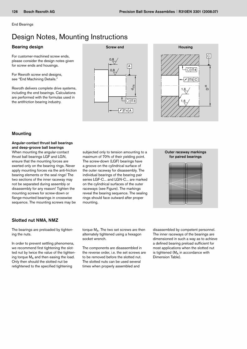
126 Bosch Rexroth AG
IT4 A
A
IT3
0,8
0,8
d IT
6
C
IT4
1,6
C
IT5
1,6
D J6
Precision Ball Screw Assemblies R310EN 3301 (2008.07)
End Bearings
Bearing design
For customer-machined screw ends, please consider the design notes given for screw ends and housings.
For Rexroth screw end designs, see “End Machining Details.”
Rexroth delivers complete drive systems, including the end bearings. Calculations are performed with the formulas used in the antifriction bearing industry.
Screw end Housing
The bearings are preloaded by tighten-ing the nuts.
In order to prevent settling phenomena, we recommend first tightening the slot-ted nut by twice the value of the tighten-ing torque MA and then easing the load. Only then should the slotted nut be retightened to the specified tightening
Angular-contact thrust ball bearings and deep-groove ball bearingsWhen mounting the angular-contact thrust ball bearings LGF and LGN, ensure that the mounting forces are exerted only on the bearing rings. Never apply mounting forces via the anti-friction bearing elements or the seal rings! The two sections of the inner raceway may not be separated during assembly or disassembly for any reason! Tighten the mounting screws for screw-down or flange-mounted bearings in crosswise sequence. The mounting screws may be
Outer raceway markings for paired bearings
subjected only to tension amounting to a maximum of 70% of their yielding point. The screw-down (LGF) bearings have a groove on the cylindrical surface of the outer raceway for disassembly. The individual bearings of the bearing pair series LGF-C... and LGN-C... are marked on the cylindrical surfaces of the outer raceways (see Figure). The markings reveal the bearing sequence. The sealing rings should face outward after proper mounting.
torque MA. The two set screws are then alternately tightened using a hexagon socket wrench.
The components are disassembled in the reverse order, i.e. the set screws are to be removed before the slotted nut.The slotted nuts can be used several times when properly assembled and
disassembled by competent personnel. The inner raceways of the bearings are dimensioned in such a way as to achieve a defined bearing preload sufficient for most applications when the slotted nut is tightened (MA in accordance with Dimension Table).
Mounting
Slotted nut NMA, NMZ
Design Notes, Mounting Instructions

127Bosch Rexroth AG
O2O1 O3
O4
h
O2O1 O3
O4
h
Precision Ball Screw AssembliesR310EN 3301 (2008.07)
Lubrication, Mounting the HousingMounting the housing SEB
Tighten the pillow block mounting screws in crosswise sequence. See table for max. tightening torque. The housing nut fixes the entire bearing unit in the housing. Use a threadlocking adhesive to secure the housing nut in place.
Note:Take care to align the screw and nut as-sembly, the bearings and the guideway precisely with one another. The Rexroth gauge is a useful aid here.
c
Mounting screw Locating pins
Tightening torques for fastening screws according to VDI 2230 for mG = mK = 0.125
Lubrication of the end bearingsBearings for ball screw assemblies are lubricated with grease for a lifetime of reliable service. It should be noted, however, that grease lubrication does not facilitate the dissipation of heat in the bearings. The bearing temperature should therefore not exceed 50°C,
particularly in machine tool applications.Angular-contact thrust ball bearings of the series LGF, LGN are lubricated for life with grease KE2P-35 per DIN 51825. For regreasing, the quantities stated in the table below can be applied via the lube ports provided on the bearings.
The maximum interval can be assumed to be 350 million revolutions, in which case the larger of the two quantities should be used. As a rule, the initial grease quantity will therefore last for the entire service life of a ball screw assembly.
Relubrication quantities for angular-contact thrust ball bearingsDesignation Quantity (g) Designation Quantity (g) Designation Quantity (g)LGN-B-0624 0.3 / 0.2LGN-B-1034 0.3 / 0.2LGN-B-1242 LGF-B-1255 0.4 / 0.3LGN-B-1747 LGF-B-1762 0.5 / 0.4LGN-B-2052 LGF-B-2068 0.8 / 0.5LGN-B-2557 LGF-B-2575 1.0 / 0.6 LGN-C-2557 LGF-C-2575 2.0 / 1.2LGN-B-3062 LGF-B-3080 1.0 / 0.6 LGN-C-3062 LGF-C-3080 2.0 / 1.2LGN-B-3572 LGF-B-3590 1.6 / 0.9LGN-A-4075 2.0 / 1.2 LGN-A-4090 LGF-B-40115 6.0 / 3.5LGN-A-5090 2.5 / 1.5 LGN-A-50110 LGF-A-50140 9.0 / 5.5
Size h O1 O2 O3 – Tapered pin (hardened)DIN 912 DIN 912 O4 – Straight pin (DIN 6325)
d0 x P (mm)8 x 2,5 8 M5 x 20 M6 x 16 4 x 2012 x 5 8 M5 x 20 M6 x 16 4 x 2016 x 5 11 M8 x 35 M10 x 25 8 x 4016 x 10 11 M8 x 35 M10 x 25 8 x 4016 x 16 11 M8 x 35 M10 x 25 8 x 4020 x 5 11 M8 x 35 M10 x 25 8 x 4020 x 20 11 M8 x 35 M10 x 25 8 x 4025 x 5 14 M10 x 40 M12 x 30 10 x 5025 x 10 14 M10 x 40 M12 x 30 10 x 5025 x 25 14 M10 x 40 M12 x 30 10 x 5032 x 5 14 M10 x 40 M12 x 30 10 x 5032 x 10 14 M10 x 40 M12 x 30 10 x 5032 x 20 14 M10 x 40 M12 x 30 10 x 5032 x 32 14 M10 x 40 M12 x 30 10 x 5040 x 5 16 M12 x 50 M14 x 35 10 x 5040 x 10 16 M12 x 50 M14 x 35 10 x 5040 x 20 16 M12 x 50 M14 x 35 10 x 5040 x 40 16 M12 x 50 M14 x 35 10 x 50
Strength class for O1; O2 M5 M6 M8 M10 M12 M14
(Nm)8.8 5.5 9.5 23 46 80 125
12.9 9.5 16.0 39 77 135 215
Steel/steel material pairing
Steel/aluminum and aluminum/aluminum material pairingsStrength class for O1; O2 M5 M6 M8 M10 M12 M14
(Nm)8.8 4.8 8.5 20 41 70 110
12.9 4.8 8.5 20 41 70 110

128 Bosch Rexroth AG
20
2000 4000 6000
1000
2000
3000
4000
5000
6000
7000
8000
9000
10000
11000
12000
8000 10000 12000
d = 30
d = 20
d=25
d = 6d = 10
1)
13000
14000
15000
16000
17000
18000
14000 16000 18000
d=50
d=40
d = 35
d = 17d = 12
d=301)
Fcomb = X · Frad + Y · Fax
F0ax p ≤ C02
Precision Ball Screw Assemblies R310EN 3301 (2008.07)
End Bearings
Design CalculationsResulting and equivalent bearing loads
For angular-contact thrust ball bearings LGN and LFG Angular-contact thrust ball bearings are preloaded. The chart shows the result-ing axial bearing load Fax as a function of preload and axial operating load FLax.For a purely axial load Fcomb = Fax.
α = pressure angleFax = resulting bearing loadFLax = operating loadX, Y = dimensionless factor
If the radial operating forces are not insignificant, the equivalent bearing loads are calculated according to formula 20 .
Bearings for ball screw assemblies are also able to accommodate tilting moments. As a rule, the moments that usually occur due to the weight and drive motion of the screw do not need to be incorporated in the calculation of the equivalent bearing load.
Internal preload limit and resulting bearing load
Limits
Operating load FLax (N)1) Four row version
Res
ultin
g be
arin
g lo
ad F
ax (N
)
α = 60° X YFaxFrad
≤ 2.171.90 0.55
FaxFrad
≤ 2.170.92 1.00
Fax = resulting axial bearing load (N) Fcomb = combined equivalent
bearing load (N) Frad = radial bearing load (N)
Permissible static axial load for bearing series LGFThe permissible static axial load of LGF-series bearings in screw-down direction is: The static axial load rating C0 is stated in the Dimension Tables.
F0ax p = permissible static axial bearing load (N)

129Bosch Rexroth AG
n +mqt1 qt2n1 n2
qtn nn100 100 100
Fm3
Fcomb13
100 100 100Fcomb2
3Fcombn
3 qtnn1nm
qt1 n2 qt2 nnnmnm
23
22
3
L · 106C
Fcomb
3
L 16666Fcomb
h nm
C
24
25
26S0 = C0
F0max
Fcomb = X · FradA + Y · Fax
B + Z 21
00 400 800 1200 1600 2000 2400 2800
500
1000
1500
2000
2500
3000
3500
4000
4500
5000
5500
6000
6500
7000
00 400 800 1200 1600 2000 2400 2800
500
1000
1500
2000
2500
3000
3500
4000
4500
5000
5500
6000
6500
7000
LGL-D-0624LGL-A-1244LGL-A-1547LGL-A-2060
Precision Ball Screw AssembliesR310EN 3301 (2008.07)
Static load safety factorThe static load safety factor for machine tools should not be lower than 4.
Service life and load safety factor
The nominal life is calculated as follows:Nominal life
Note:Take into account the dynamic load rating of the nut!
Fcomb1 ... Fcombn = combined equivalent axial load in phases 1 ... n (N)
Fm = dynamic equivalent bearing load (N)n1 ... nn = speeds in phases 1 ... n (min–1)nm = average speed (min–1)qt1 ... qtn = discrete time steps in phases 1 ... n (%)
F0max = maximum static load (N)C0 = static load rating (N)S0 = static load safety factor (–)
C = dynamic bearing load rating (N)Fcomb = combined equivalent bearing load (N)L = nominal service life in revolutions (–)Lh = nominal service life in operating hours (h)nm = average speed (min–1)
Average speed and average bearing loadWhen the bearing load varies in steps over a specific period of time, calculate the dynamic equivalent bearing load using formula 22 . When the speed varies, use formula 23 .In these formulas qt denotes the discrete time steps for the individual phases in %.
Resulting and equivalent bearing loads
For angular-contact thrust ball bearings LGLBefore determining the combined equivalent load Fcomb, the bearing size must be checked against the chart for static load limits.A bearing will only be suitable for a particular application when the intersec-tion point between the axial and radial bearing loads lies below the load limit curve.
Fax = axial bearing load (N)Fcomb = combined equivalent
bearing load (N)Frad = radial bearing load (N)X, Y, Z = calculation factors (–)A, B = exponents (–)
Bearing size X Y Z A BLGL-D-0624 0.003 0.1300 140 1.90 1.40LGL-A-1244 0.076 0.0460 580 1.28 1.30LGL-A-1547 0.022 0.0110 540 1.45 1.50LGL-A-2060 0.017 0.0082 960 1.45 1.50
Rad
ial l
oad
on b
earin
g F r
ad (
N)
Axial load on bearing Fax (N)
Static load limit

130 Bosch Rexroth AG Precision Ball Screw Assemblies R310EN 3301 (2008.07)
Bosch Rexroth AGLinear Motion andAssembly Technologies97419 Schweinfurt / Germany
Telephone +49 9721 937-0Fax +49 9721 937-288e-mail [email protected]
To: Precision Ball Screw Assemblies Department
Design Calculation Service Form
Alternatively, technical design calculation can be performed by the customer with our WINKGT software.
Screw end fixity Selected:
Installation conditions (enclose drawings/sketches if possible!)
(see pages 124/125)
Drawing enclosed
Type of lubrication: Operating temperature: °C - min/max. / °CExceptional operating conditions:
fixed fixed floating fixedI II III IV
Operating conditions
Application: New design Revised design
Loads (N) Speeds (1/min) Discrete time steps (%)F1 = at n1 = for q1 =F2 = at n2 = for q2 =F3 = at n3 = for q3 =F4 = at n4 = for q4 =F5 = at n5 = for q5 =F6 = at n6 = for q6 =Average load (see p. 120) Average speed (see p. 120) Sum of time stepsFm = nm = Q = 100%Maximum static load: NRequired service life Operating hours or x 106 ball screw revolutions
Screw end fixity: horizontal vertical
fixed floating floating free
SenderOEM User DistributorCompany NameAddress Department
TelephoneFaxe-mail

131Bosch Rexroth AGPrecision Ball Screw AssembliesR310EN 3301 (2008.07)
Bosch Rexroth AGLinear Motion andAssembly Technologies97419 Schweinfurt / Germany
Telephone +49 9721 937-0Fax +49 9721 937-288e-mail [email protected]
To: Precision Ball Screw Assemblies Department
Inquiry/Order FormFor elucidations, see page 20/21.Note: The processing of Inquiries/Orders based on customer drawings is also possible of course.
Comments:
Example of an order
Ball screw assembly
Screw SN-R X X
SEM-E-S 20 x 5R x 3 - 4
20 x 5R x 3
1 2 T7
T7
R
R
81Z120
00T200
41Z120
00T200
1250
1250
1 1
1 0
Ball screw assembly
Screw SN-R X X x x
x x -
Stückzahl Abnahme von ……… Stück, ……… monatlich, ……… jährlich, je Bestellung, oder ……………………
Bemerkungen ……………………………………………………………………………………………………………………..
Ball screw assembly
Screw SN-R X X x x
x x -
Ball screw assembly
Screw SN-R X X x x
x x -
Bemerkungen:
Anlage: Zeichnung liegt bei Sonstiges
Bestellbeispiel
SenderOEM User DistributorCompany NameAddress Department
TelephoneFaxe-mail

SingaporeBosch Rexroth Pte. Ltd.15D Tuas Road638520 SingaporeTel. +65 6861 8733Fax +65 6861 1825
CanadaBosch Rexroth Canada Corp.3426 Mainway DriveBurlington, Ontario L7M 1A8Tel. +1 905 335-5511Fax +1 905 335-4184
USABosch Rexroth Corporation14001 South Lakes DriveCharlotte, NC 28273Tel. +1 800 REXROTH +1 800 739 7684Fax +1 704 583 0523
AustraliaBosch Rexroth Pty. Ltd.3 Valediction RoadKings Park, NSW 2148, SydneyTel. +61 2 9831 7788Fax +61 2 9831 5553
Great Britain Bosch Rexroth LimitedCromwell RoadSt. Neots, HuntingdonCambs. PE19 2ES Tel. +44 1480 223 298Fax +44 1480 470 789
Your sales partner
Bosch Rexroth AGLinear Motion and Assembly TechnologiesErnst-Sachs-Strasse 10097424 Schweinfurt, GermanyTel. +49 9721 937-0 Fax +49 9721 937-275www.boschrexroth.com/brl
Subject to technical modifications
© Bosch Rexroth AG 2008Printed in GermanyR310EN 3301 (2008.07) EN • BRL/MKT2