retrofit simulation report - universidade do...
TRANSCRIPT
IEA ECBCS Annex 50Prefabricated Systems for Low Energy
Renovation of Residential Buildings
RetrofitSimulation Report
March 2011
IEA E
CBC
S A
nnex
50 -
Ret
rofi
t Si
mula
tion
Rep
ort
AEE - Institute for Sustainable Technologies (AEE-INTEC), Austria
Enviros s.r.o., Czech RepublicBrno University of Technology, Institute of Building Services, Czech Republic
Centre scientifique et technique du bâtiment CSTB, FranceSaint-Gobain Isover, E3 Performances / ArcelorMittal, FranceEDF, AETIC, ALDES, Vinci Constructions, France
Energy Research Centre of the Netherlands ECN, Netherlands
Porto University, Faculty of Engineering, PortugalUniversity of Minho, Civil Engineering Department, Construction and Technology Group, Portugal
CNA Arkitektkontor AB, SwedenEnergy and Building Design, Lund Institute of Technology, Sweden
Lucerne University of Applied Sciences and Arts, Technology and Architecture, SwitzerlandUniversity of Applied Sciences Northwestern Switzerland, School of Architecture,Civil Engineering and Geomatics, SwitzerlandSwiss Federal Laboratories for Materials Science and Technology Empa,Building Science and Technology Laboratory, Switzerland
Research Partners:
Published by:

IEA ECBCS Annex 50 Prefabricated Systems for Low Energy
Renovation of Residential Buildings
Retrofit Simulation Report
March 2011
This report documents results of cooperative work performed under the IEA Program for Energy Conservation in Buildings and Community Systems, Annex 50 “Prefabricated
Systems for Low Energy Renovation of Residential Buildings”
Principal Author:
Gerhard Zweifel, Lucerne University of Applied Sciences and Arts, Switzerland
With contributions from:
Marie Descamps, University of Liège, Belgium Robert Fischer and Sven Moosberger,
Lucerne University of Applied Sciences and Arts, Switzerland Ondrej Sikula, University of Brno, Czech Republic
Pedro Silva and Manuela Almeida, University of Minho, Portugal

2
Retrofit Simulation Report IEA - International Energy Agency ECBCS - Energy Conservation in Buildings and Community Systems Annex 50 – Prefabricated Systems for Low Energy Renovation of Residential Buildings Operating Agent: Mark Zimmermann, Empa, Switzerland Funded by the Swiss Federal Office of Energy (SFOE) Published by: Empa, Building Science and Technology Lab CH-8600 Duebendorf Switzerland E-mail: [email protected] http://www.empa-ren.ch/A50.htm http://www.ecbcs.org ©Copyright: Copying with reference to “Retrofit Simulation Report IEA ECBCS Annex 50” permitted Empa - Swiss Federal Laboratories for Materials Science and Technology, March 2011

IEA ECBCS Annex 50 – Prefab Retrofit Retrofit Simulation Report
3
Preface International Energy Agency The International Energy Agency (IEA) was established in 1974 within the framework of the Organisa-tion for Economic Co-operation and Development (OECD) to implement an international energy pro-gramme. A basic aim of the IEA is to foster co-operation among the twenty-eight IEA participating countries and to increase energy security through energy conservation, development of alternative en-ergy sources and energy research, development and demonstration (RD&D). Energy Conservation in Buildings and Community Systems The IEA co-ordinates research and development in a number of areas related to energy. The mission of one of those areas, the ECBCS - Energy Conservation for Building and Community Systems Programme, is to develop and facilitate the integration of technologies and processes for energy efficiency and con-servation into healthy, low emission, and sustainable buildings and communities, through innovation and research. The research and development strategies of the ECBCS Programme are derived from research drivers, national programmes within IEA countries, and the IEA Future Building Forum Think Tank Workshop, held in March 2007. The R&D strategies represent a collective input of the Executive Committee mem-bers to exploit technological opportunities to save energy in the buildings sector, and to remove techni-cal obstacles to market penetration of new energy conservation technologies. The R&D strategies apply to residential, commercial, office buildings and community systems, and will impact the building indus-try in three focus areas of R&D activities:
Dissemination Decision-making Building products and systems
The Executive Committee
Overall control of the programme is maintained by an Executive Committee, which not only monitors existing projects but also identifies new areas where collaborative effort may be beneficial. To date the following projects have been initiated by the executive committee on Energy Conservation in Buildings and Community Systems (completed projects are identified by *): Annex 1: Load Energy Determination of Buildings* Annex 2: Ekistics and Advanced Community Energy Systems* Annex 3: Energy Conservation in Residential Buildings* Annex 4: Glasgow Commercial Building Monitoring* Annex 5: Air Infiltration and Ventilation Centre Annex 6: Energy Systems and Design of Communities* Annex 7: Local Government Energy Planning* Annex 8: Inhabitants Behaviour with Regard to Ventilation* Annex 9: Minimum Ventilation Rates* Annex 10: Building HVAC System Simulation* Annex 11: Energy Auditing* Annex 12: Windows and Fenestration* Annex 13: Energy Management in Hospitals* Annex 14: Condensation and Energy* Annex 15: Energy Efficiency in Schools* Annex 16: BEMS 1- User Interfaces and System Integration* Annex 17: BEMS 2- Evaluation and Emulation Techniques* Annex 18: Demand Controlled Ventilation Systems* Annex 19: Low Slope Roof Systems* Annex 20: Air Flow Patterns within Buildings* Annex 21: Thermal Modelling* Annex 22: Energy Efficient Communities*
IEA ECBCS Annex 50 – Prefab Retrofit Retrofit Simulation Report
4
Annex 23: Multi Zone Air Flow Modelling (COMIS)* Annex 24: Heat, Air and Moisture Transfer in Envelopes* Annex 25: Real time HEVAC Simulation* Annex 26: Energy Efficient Ventilation of Large Enclosures* Annex 27: Evaluation and Demonstration of Domestic Ventilation Systems* Annex 28: Low Energy Cooling Systems* Annex 29: Daylight in Buildings* Annex 30: Bringing Simulation to Application* Annex 31: Energy-Related Environmental Impact of Buildings* Annex 32: Integral Building Envelope Performance Assessment* Annex 33: Advanced Local Energy Planning* Annex 34: Computer-Aided Evaluation of HVAC System Performance* Annex 35: Design of Energy Efficient Hybrid Ventilation (HYBVENT)* Annex 36: Retrofitting of Educational Buildings* Annex 37: Low Exergy Systems for Heating and Cooling of Buildings (LowEx)* Annex 38: Solar Sustainable Housing* Annex 39: High Performance Insulation Systems* Annex 40: Building Commissioning to Improve Energy Performance* Annex 41: Whole Building Heat, Air and Moisture Response (MOIST-ENG)* Annex 42: The Simulation of Building-Integrated Fuel Cell and Other Cogeneration Systems
(FC+COGEN-SIM)* Annex 43: Testing and Validation of Building Energy Simulation Tools* Annex 44: Integrating Environmentally Responsive Elements in Buildings* Annex 45: Energy Efficient Electric Lighting for Buildings* Annex 46: Holistic Assessment Tool-kit on Energy Efficient Retrofit Measures for
Government Buildings (EnERGo)* Annex 47: Cost Effective Commissioning of Existing and Low Energy Buildings* Annex 48: Heat Pumping and Reversible Air Conditioning* Annex 49: Low Exergy Systems for High Performance Buildings and Communities* Annex 50: Prefabricated Systems for Low Energy Renovation of Residential Buildings* Annex 51: Energy Efficient Communities Annex 52: Towards Net Zero Energy Solar Buildings Annex 53: Total Energy Use in Buildings: Analysis & Evaluation Methods Annex 54: Analysis of Micro-Generation & Related Energy Technologies in Buildings Annex 55: Reliability of Energy Efficient Building Retrofitting - Probability Assessment of Perform-
ance & Cost (RAP-RETRO) Annex 56: Energy and Greenhouse Optimised Building Renovation Working Group - Energy Efficiency in Educational Buildings* Working Group - Indicators of Energy Efficiency in Cold Climate Buildings* Working Group - Annex 36 Extension: The Energy Concept Adviser* Working Group - Energy Efficient Communities * completed
IEA ECBCS Annex 50 – Prefab Retrofit Retrofit Simulation Report
5
Annex 50 “Prefabricated Systems for Low Energy Renovation of Residential Buildings”
Energy conservation is largely dominated by existing buildings. In most industrialized countries new buildings will only contribute 10% - 20% additional energy consumption by 2050 whereas more than 80% will be influenced by the existing building stock. If building renovation continues at the current rate and with the present common policy, between one to over four centuries will be necessary to improve the building stock to the energy level of current new construction. Currently, most present building renovations address isolated building components, such as roofs, fa-çades or heating systems. This often results in inefficient and in the end expensive solutions, without an appropriate long term energy reduction. Optimal results can not be achieved by single renovation measures and new problems could arise, including local condensation or overheating. The objectives of this Annex have been the development and demonstration of an innovative whole building renovation concept for typical apartment buildings. The concept is based on largely standard-ised façade and roof systems that are suitable for prefabrication. The highly insulated new building en-velope includes the integration of a ventilation system. The concept is focused on typical apartment buildings that represent approximately 40% of the Euro-pean dwelling stock. The advantages include:
Achieving energy efficiency and comfort for existing apartment buildings comparable to new ad-vanced low energy buildings i.e. 30-50 kWh/(m²·y);
Optimised constructions and quality and cost efficiency due to prefabrication; Opportunity to create attractive new living space in the prefabricated attic space and by in-
cooperating existing balconies into the living space; A quick renewal process with minimised disturbances for the inhabitants.
The deliverables of the project are: Retrofit Strategies Design Guide
A building retrofit strategies guide [II] documenting typical solutions for whole building renovations, in-cluding prefabricated roofs with integrated HVAC components and for advanced façade renovation. The report is supplemented by the Retrofit Simulation Report [IX] and an electronic ‘Retrofit Advisor’ [V] that allows a computer-based evaluation of suitable renovation strategies. Retrofit Module Design Guide Guidelines for system evaluation, design, construction process and quality assurance for prefabricated renovation modules [III]. This publication includes the technical documentation of all developed renova-tion solutions. Case Study Building Renovations Case studies of seven demonstration buildings in Austria, Netherlands, Sweden and Switzerland [IV]. Technical Summary Report A summary report for a broad audience, demonstrating the potential of prefabricated retrofit [I]. Additional publications are:
Annex 50 Fact Sheet, offering a short overview of the project and its achievements Building Typology and Morphology of Swiss and French Multi-Family Homes [VI], [VII], [VIII]
Home Pages: www.empa-ren.ch/A50.htm, www.ecbcs.org/annexes/annex50.htm Participating Countries: Austria, Czech Republic, France, Netherlands, Portugal, Sweden, Switzerland

IEA ECBCS Annex 50 – Prefab Retrofit Retrofit Simulation Report
6
IEA ECBCS Annex 50 – Prefab Retrofit Retrofit Simulation Report
7
Retrofit Simulation Report
Summary The goal of the calculation exercise was to show the order of magnitude of the measures to be taken with an example retrofit building at different locations in order to reach the energy demand goal of 30 to 50 kWh/a per m2 gross heated area of primary energy for heating, ventilation and domestic hot water production. The measures to be taken include:
Improved building insulation, including window replacements and additional insulation of opaque surfaces
Application of a ventilation system with heat recovery Use of renewable energy sources, especially solar energy for domestic hot water production Improved energy production (by replacement of the heat generation), possibly including elec-
tricity production The Swiss potential demonstration building “Elfenau”, located in Lucerne, was chosen as the example building, being considered as typical enough for all participant countries. The building is one half of a multi-family house with three regular floors with 2 flats each, an unheated basement with garages, cel-lar rooms and a heating central, and an attic floor with two small single room flats and unheated attic space. The construction is rendered double brick masonry with concrete floor slabs and a concrete basement. The sloped roof is tile covered. Windows are double glazed with a wood frame. The radiator heating system is served by an oil fired boiler, which also provides domestic hot water. Ventilation is purely natural through open windows. A three step procedure was applied to involve the different project partners with different calculation tools in the exercise:
In a first step, the building was calculated “as is” at its original location, in order to compare the results achieved by the different partners with different tools. 4 partners (Belgium, Czech Re-public, Portugal and Switzerland) with 5 different tools, 3 simplified tools (PEB - CALE2, RCCTE) and 3 detailed simulation programs (Bsim 2000, Energy+ and IDA-ICE 4.0), participated.
In a second step, the same building was calculated at a location of the participant’s country, in order to show the influence of the location on the same building. The same 5 participants per-formed these calculations with the same tools.
In the third step, the building, retrofitted according to the strategy defined by the Swiss national retrofit team, had to be calculated at the location of the participant, and the respective meas-ures had to be defined and quantified. Two partners (Portugal and Switzerland) with 3 tools (RCCTE, Energy+ and IDA-ICE 4.0) participated. The Swiss participant also ran simulations for the northern climate of Stockholm.
The step 1 calculations showed a systematic difference between the results for the useful energy de-mand for space heating (without domestic hot water) from the simplified calculation tools (137-147 kWh/(m²·y)) and from the detailed simulation programs (94-105 kWh/(m²·y)). By an additional calcula-tion with a detailed simulation tool (IDA-ICE) it could be confirmed that this difference originates to a large extent by the different treatment of losses through or against unheated spaces like staircases, basements and unheated attic spaces. The accordingly simplified model lead to a value of 136 kWh/(m²·y). This also showed that there is a considerable reserve in the energy demand calculated by the simplified calculations for the buildings considered here due to the fact mentioned above. From the step 2 calculations it could be seen that the energy demand of the building reacts as expected to the different climates for the locations considered (slightly lower heating demand in Liège, Belgium, slightly higher heating demand in Brno, Czech republic and considerably lower heating demand and a potential for cooling, if the respective measures are not taken, for the Portuguese location of Gui-marães). For the step 3 calculations, being the main step of this study, a retrofit strategy developed by the Swiss team was applied, which includes an extension of the heated space in the attic and basement floors, the enclosure of the balconies and an additional elevator tower with access balconies. The result of this step
IEA ECBCS Annex 50 – Prefab Retrofit Retrofit Simulation Report
8
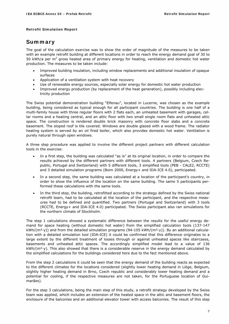
show to the necessary building modifications to be applied at the different locations in order to reach the goal of a primary energy consumption for heating, ventilation and domestic hot water consumption of 30 to 50 kWh/(m²·y). According to the specifications, a mechanical ventilation system with an annual heat recovery efficiency of 0.8 had to be considered.
For the three climates of Lucerne, Stockholm and Guimarães, the measures (U-values) to reach the goal of 30 kWh/(m²·y) were identified as:
Lucerne Stockholm Guimarães
Exterior walls – new parts - retrofitted existing walls
W/(m2·K) 0.15 0.2
0.15 <0.1*
0.23 0.23
Basement interior walls to non-heated zone W/(m2·K) 0.55 0.55 0.73
Balcony floor W/(m2·K) 0.15 0.15 0.67
Interior roof in contact with attic non-heated zone W/(m2·K) 0.55 0.55 0.34
Window frame W/(m2·K) 1.60 1.60 1.50
Glazing, U-value g-value
W/(m2·K) -
0.8 0.5
0.8 0.5
1.1 0.45
Collector area m2 22.7 22.7 19.8
*or a different set of measures
And for 50 kWh/(m²·y)
Lucerne Stockholm Guimarães
Exterior walls – new parts - retrofitted existing walls
W/(m2·K) 0.15 0.4
0.15 0.2
0.44 0.44
Basement interior walls to non-heated zone W/(m2·K) 0.55 0.55 2.43
Balcony floor W/(m2·K) 0.15 0.15 0.67
Interior roof in contact with attic non-heated zone W/(m2·K) 0.55 0.55 0.50
Window frame W/(m2·K) 1.60 1.60 2.35
Glazing, U-value g-value
W/(m2·K) -
0.8 0.5
0.8 0.5
2.1 0.45
Collector area m2 22.7 22.7 15.84
For the Swiss climate – assuming that the elements added new to the building such as balcony enclo-sures, new elements in the attic floor and the roof are made according to Swiss 2010 standard target quality, i.e. having a U-Value of 0.15 W/(m²·K) – the value of 50 kWh/(m²·K) is not really a challenge. To reach the value of 30 kWh/(m²·y), measures were identified in dependence of the heat generation system. While the CHP according to the specifications and a gas boiler lead to nearly equal results given in the table above, the use of a heat pump allows for U-values for the existing building elements of 0.4 W/(m²·K), the limit being defined by the comfort and damage prevention requirements rather than by the energy target. For the northern climate of Stockholm, the same measures are sufficient to get under the value of 50 kWh/(m²·y). To reach 30 kWh/(m²·y), considerably lower U-values would be needed in all parts.
IEA ECBCS Annex 50 – Prefab Retrofit Retrofit Simulation Report
9
Table of Content
1. Goal 11
2. Procedure 11
2.1. Object choice 11
2.1.1. Requirements 11
2.1.2. Choice 11
2.2. Calculation procedure 12
2.2.1. Calculation steps 12
2.2.2. Overview of the calculations performed 12
2.2.3. Step 1 calculations 13
2.2.4. Step 2 calculations 13
2.2.5. Step 3 calculations 13
3. Results 14
3.1. Step 1 and 2 results 14
3.1.1. Reporting 14
3.1.2. Step 1 results 14
3.1.3. Step 1 results analysis 15
3.1.4. Step 2 results 15
3.2. Step 3 results 15
3.2.1. Results for Lucerne 16
3.2.2. Results for Stockholm 18
3.2.3. Results for Guimarães 18
4. Summary and Conclusions 19
5. References 21
Appendix A Step 1 and 2 Specification 22
Appendix B Plans of the Original Building 30
Appendix C Step 3 retrofit strategy 33
Appendix D Step 3 Retrofit Case - Specification 36
Appendix E Step 1 and 2 Calculation Reports for Simplified Calculations 39
Appendix F Step 1 and 2 Calculation Report from HSLU 52
Appendix G Step 1 and 2 Calculation report from University of Minho 66
Appendix H Step 3 Retrofit Case Calculation Report for the Swiss Location of Lucerne 69
Appendix I Step 3 Retrofit Case Calculation Report for Portuguese Location of Guimarães 84

IEA ECBCS Annex 50 – Prefab Retrofit Retrofit Simulation Report
10
IEA ECBCS Annex 50 – Prefab Retrofit Retrofit Simulation Report
11
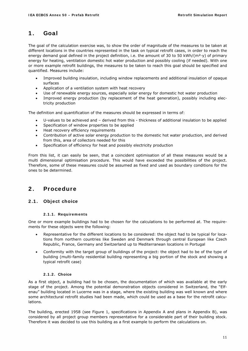
1. Goal The goal of the calculation exercise was, to show the order of magnitude of the measures to be taken at different locations in the countries represented in the task on typical retrofit cases, in order to reach the energy demand goal defined in the project definition, i.e. the amount of 30 to 50 kWh/(m²·y) of primary energy for heating, ventilation domestic hot water production and possibly cooling (if needed). With one or more example retrofit buildings, the measures to be taken to reach this goal should be specified and quantified. Measures include:
Improved building insulation, including window replacements and additional insulation of opaque surfaces
Application of a ventilation system with heat recovery Use of renewable energy sources, especially solar energy for domestic hot water production Improved energy production (by replacement of the heat generation), possibly including elec-
tricity production
The definition and quantification of the measures should be expressed in terms of:
U-values to be achieved and – derived from this - thickness of additional insulation to be applied Specification of window properties to be applied Heat recovery efficiency requirements Contribution of active solar energy production to the domestic hot water production, and derived
from this, area of collectors needed for this Specification of efficiency for heat and possibly electricity production
From this list, it can easily be seen, that a coincident optimisation of all these measures would be a multi dimensional optimisation procedure. This would have exceeded the possibilities of the project. Therefore, some of these measures could be assumed as fixed and used as boundary conditions for the ones to be determined.
2. Procedure
2.1. Object choice
2.1.1. Requirements
One or more example buildings had to be chosen for the calculations to be performed at. The require-ments for these objects were the following:
Representative for the different locations to be considered: the object had to be typical for loca-tions from northern countries like Sweden and Denmark through central European like Czech Republic, France, Germany and Switzerland up to Mediterranean locations in Portugal
Conformity with the target group of buildings of the project: the object had to be of the type of building (multi-family residential building representing a big portion of the stock and showing a typical retrofit case)
2.1.2. Choice
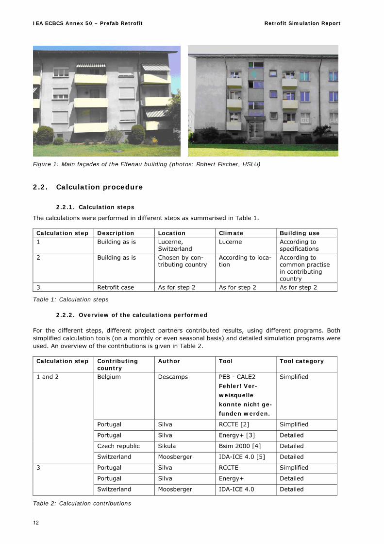
As a first object, a building had to be chosen, the documentation of which was available at the early stage of the project. Among the potential demonstration objects considered in Switzerland, the “Elf-enau” building located in Lucerne was in a stage, where the existing building was well known and where some architectural retrofit studies had been made, which could be used as a base for the retrofit calcu-lations. The building, erected 1958 (see Figure 1, specifications in Appendix A and plans in Appendix B), was considered by all project group members representative for a considerable part of their building stock. Therefore it was decided to use this building as a first example to perform the calculations on.
IEA ECBCS Annex 50 – Prefab Retrofit Retrofit Simulation Report
12
Figure 1: Main façades of the Elfenau building (photos: Robert Fischer, HSLU)
2.2. Calculation procedure
2.2.1. Calculation steps
The calculations were performed in different steps as summarised in Table 1. Calculation step Description Location Climate Building use 1 Building as is Lucerne,
Switzerland Lucerne According to
specifications 2 Building as is Chosen by con-
tributing country According to loca-tion
According to common practise in contributing country
3 Retrofit case As for step 2 As for step 2 As for step 2
Table 1: Calculation steps
2.2.2. Overview of the calculations performed For the different steps, different project partners contributed results, using different programs. Both simplified calculation tools (on a monthly or even seasonal basis) and detailed simulation programs were used. An overview of the contributions is given in Table 2. Calculation step Contributing
country Author Tool Tool category
Belgium Descamps PEB - CALE2
Fehler! Ver-
weisquelle
konnte nicht ge-
funden werden.
Simplified
Portugal Silva RCCTE [2] Simplified
Portugal Silva Energy+ [3] Detailed
Czech republic Sikula Bsim 2000 [4] Detailed
1 and 2
Switzerland Moosberger IDA-ICE 4.0 [5] Detailed
Portugal Silva RCCTE Simplified
Portugal Silva Energy+ Detailed
3
Switzerland Moosberger IDA-ICE 4.0 Detailed
Table 2: Calculation contributions
IEA ECBCS Annex 50 – Prefab Retrofit Retrofit Simulation Report
13
Detailed calculations are room or room group based simulations with a time step of 1 h or less, whereas simplified calculations are monthly or seasonally based and generally treat the building as a whole.
2.2.3. Step 1 calculations The goal of step 1 was, to compare the results from the different tools used by the different countries, in order to get an indication of the accuracy of the results obtained. The use of different level tools led to the expectation, that there would be differences in the results, which would have to be explained. The calculations were performed based on the following information made available to the contributors:
Specification document (Appendix A) A set of plans of the building, including situation, floor plans of all floors, façade views and cross
sections (Appendix B) A set of photographs of the building (source: Robert Fischer, HSLU – T&A, not shown here) Climatic data for step 1 (Lucerne) in monthly and hourly resolution A set of primary energy factors for the evaluation of delivered energy carriers (see Appendix A)
The building use data were derived from the Swiss standard for heating energy performance of buildings (SIA 380/1 [6]). The global values for occupancy, lighting and equipment from this standard were translated into schedules, considering seasonal variations like day length for lighting etc., in order to provide enough detailed information for the detailed tools. This way it was made sure, that there was at least no difference between the detailed and simplified tools from this side. The specifications also included “fuzzy” information on heat and water distribution and generation, to the contributors’ interpretation. This information was unified later in the process, see chapter 3 below.
2.2.4. Step 2 calculations In step 2, the influence of the different locations was to be shown. The calculations were made based on the same specification as step 1. Instead of the provided climate and use information, the contributor’s own information was used.
2.2.5. Step 3 calculations In step 3, the retrofit measures were applied, specified and quantified. The base of this calculation was, in respect of building geometry, a retrofit strategy in form of a set of new plans, provided by the Swiss retrofit team (Appendix C). This strategy considers the situation that retrofit measures often not only consist of an energy related improvement, but include building enhancements in form of additional space, added elements needed for compliance with current standards and regulations (not only energy, but security, handicapped ac-cessibility etc.). The strategy, shown in Appendix C, includes an added lift tower and attached balconies, an extension of usable area in the attic and basement floors and the inclusion of former balconies in the heated area. In addition to the retrofit strategy, a further specification document was handed out (Appendix D).
IEA ECBCS Annex 50 – Prefab Retrofit Retrofit Simulation Report
14
3. Results
3.1. Step 1 and 2 results
3.1.1. Reporting
Reports were received from all contributors, giving the required results and additional information on the calculations, like assumptions made and more detailed results. These can be found in appendices E, F and G. These reports are given in the format in which they were received from the contributors. Therefore the format is not the same for all, and a comparison is difficult. However, the different tools used by the contributors provide different output formats which sometimes cannot be changed, includ-ing even aspects like the language in some cases. The relevant numbers were extracted by the coordi-nator and summarised in the following paragraphs.
3.1.2. Step 1 results
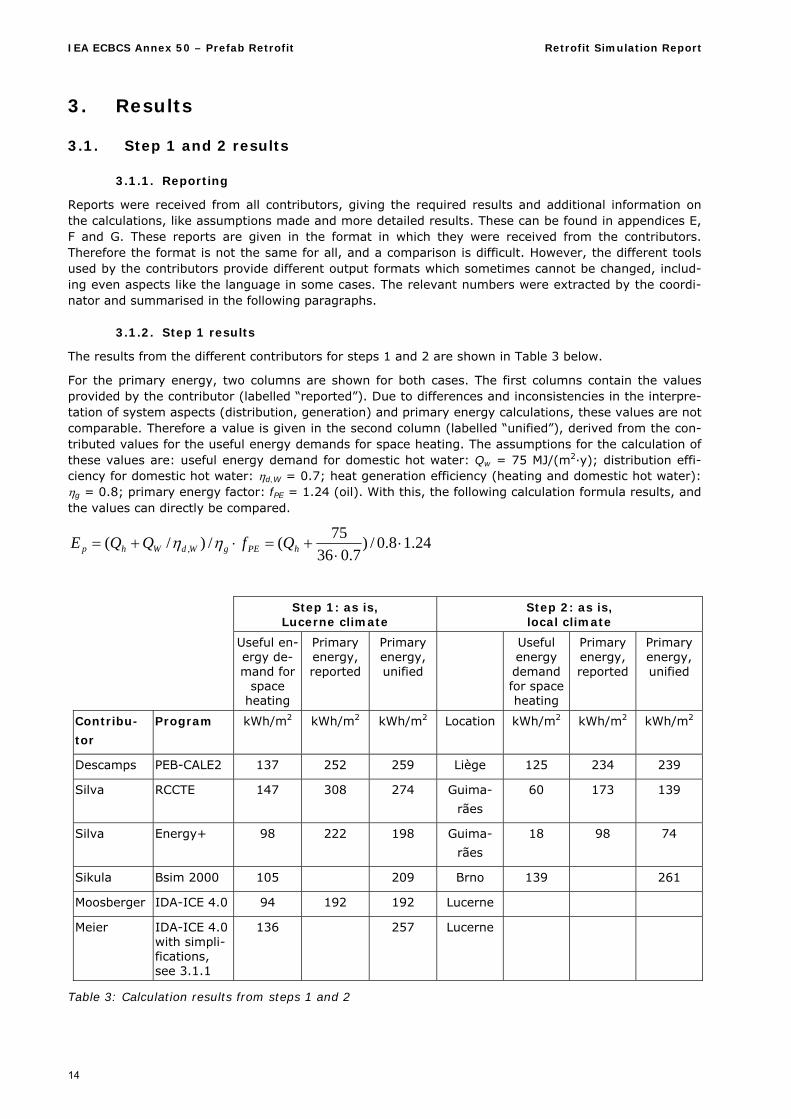
The results from the different contributors for steps 1 and 2 are shown in Table 3 below.
For the primary energy, two columns are shown for both cases. The first columns contain the values provided by the contributor (labelled “reported”). Due to differences and inconsistencies in the interpre-tation of system aspects (distribution, generation) and primary energy calculations, these values are not comparable. Therefore a value is given in the second column (labelled “unified”), derived from the con-tributed values for the useful energy demands for space heating. The assumptions for the calculation of these values are: useful energy demand for domestic hot water: Qw = 75 MJ/(m2·y); distribution effi-ciency for domestic hot water: d,W = 0.7; heat generation efficiency (heating and domestic hot water): g = 0.8; primary energy factor: fPE = 1.24 (oil). With this, the following calculation formula results, and the values can directly be compared.
24.18.0/)7.036
75(/)/( ,
hPEgWdWhp QfQQE
Step 1: as is,
Lucerne climate Step 2: as is, local climate
Useful en-ergy de-mand for
space heating
Primary energy, reported
Primary energy, unified
Useful energy demand for space heating
Primary energy, reported
Primary energy, unified
Contribu-
tor
Program kWh/m2 kWh/m2 kWh/m2 Location kWh/m2 kWh/m2 kWh/m2
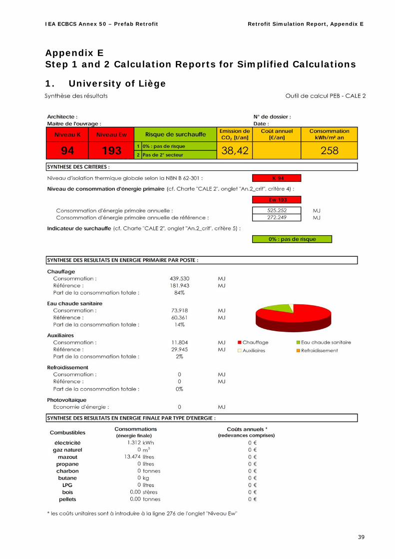
Descamps PEB-CALE2 137 252 259 Liège 125 234 239
Silva RCCTE 147 308 274 Guima-
rães
60 173 139
Silva Energy+ 98 222 198 Guima-
rães
18 98 74
Sikula Bsim 2000 105 209 Brno 139 261
Moosberger IDA-ICE 4.0 94 192 192 Lucerne
Meier IDA-ICE 4.0 with simpli-fications, see 3.1.1
136 257 Lucerne
Table 3: Calculation results from steps 1 and 2
IEA ECBCS Annex 50 – Prefab Retrofit Retrofit Simulation Report
15
From Table 3 it can be seen that there is a variety in the resulting energy demand of +/- 20% in pri-mary energy against the average value. In useful heating energy demand, the variety is even close to +/- 25%. This result is not a surprise, considering the different tool categories involved.
3.1.3. Step 1 results analysis
A systematic difference can be recognised between the results for the useful energy demand for space heating achieved with the simplified tools (values around 142 +/- 5 kWh/m²) and the detailed simula-tion programs (values around 100 +/- 6 kWh/m²). Therefore there must be reasons to be identified for these differences. From the coordinator’s experience, the following areas of possible reasons were iden-tified to be verified by the additional cases:
Staircase: In simplified calculations, the unheated staircase is usually counted as a heated space, because it is within the insulation perimeter. In the detailed simulations it is treated as an unheated space, its temperature being calculated as a result of the heat flows, which is closer to reality.
Unheated attic and unheated basement: In simplified calculations, the walls towards these rooms are calculated as against outdoor cli-mate with a correction factor according to European standards („b-factor“). This is a simplifica-tion, and the given b-factors are overestimating the losses through these walls to be on the safe side. In the detailed simulations, these rooms are again more accurately treated as unheated spaces.
An additional round of simulations with the IDA-ICE program was performed by Stefan Meier (HSLU). A modified IDA-ICE input was created, with the simplifications according to the simplified tools listed above in place. The results are given in the bottom line of Table 3. The value of 136 kWh/(m2·y) for the useful heating energy demand is about equal to the lower result of the simplified tools. Some further differences of minor importance may originate from other differences, e.g. in control. This result confirms the coordinator’s suspicion and shows, that there is a considerable reserve in the simplified tools due to “safe side” assumptions.
3.1.4. Step 2 results The results for the Belgian location are quite similar to the original location results, slightly lower, which could be expected due to the slightly milder, more maritime and lower altitude climate. In Brno, the cli-mate seems to be somewhat more severe, which could also be expected, regarding the more continen-tal location and higher latitude. For the Mediterranean Guimarães location, the heating energy demand is, as expected, considerably lower. Here the difference between the simplified and detailed calculation becomes even more impor-tant, the latter showing results even close to 0 for the useful heating energy demand. It has to be stated that the primary energy results for this case do not contain any cooling contribution, since exist-ing buildings do not have the respective equipment although it might be needed from a thermal comfort perspective.
3.2. Step 3 results
Contributions for the step 3 calculations were received from two sources:
Simulations with IDA-ICE 4.0 from HSLU (Sven Moosberger), for original Swiss location (Lu-cerne); these were complimented by a few calculations for a Nordic climate (Stockholm).
Calculations with both a simplified tool (RCCTE) and a detailed simulation program (Design-Builder -> Energy+) from University of Minho (Pedro Silva) for the Mediterranean location of Guimarães.
IEA ECBCS Annex 50 – Prefab Retrofit Retrofit Simulation Report
16
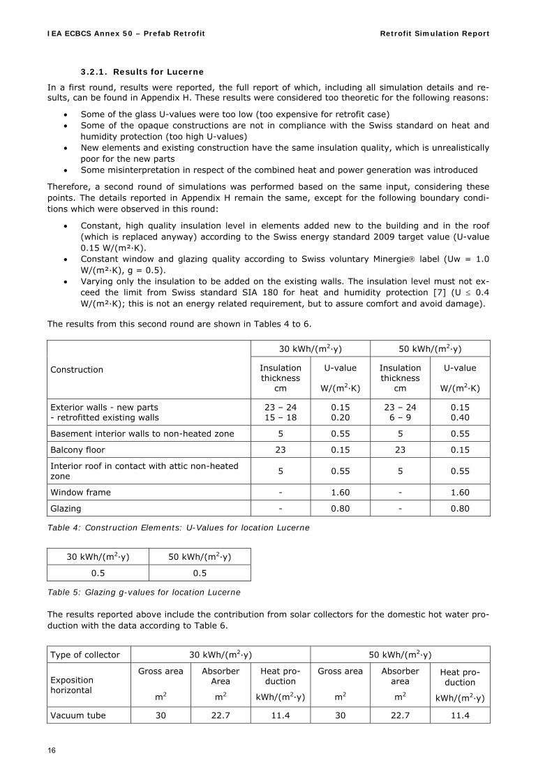
3.2.1. Results for Lucerne
In a first round, results were reported, the full report of which, including all simulation details and re-sults, can be found in Appendix H. These results were considered too theoretic for the following reasons:
Some of the glass U-values were too low (too expensive for retrofit case) Some of the opaque constructions are not in compliance with the Swiss standard on heat and
humidity protection (too high U-values) New elements and existing construction have the same insulation quality, which is unrealistically
poor for the new parts Some misinterpretation in respect of the combined heat and power generation was introduced
Therefore, a second round of simulations was performed based on the same input, considering these points. The details reported in Appendix H remain the same, except for the following boundary condi-tions which were observed in this round:
Constant, high quality insulation level in elements added new to the building and in the roof (which is replaced anyway) according to the Swiss energy standard 2009 target value (U-value 0.15 W/(m²·K).
Constant window and glazing quality according to Swiss voluntary Minergie label (Uw = 1.0 W/(m²·K), g = 0.5).
Varying only the insulation to be added on the existing walls. The insulation level must not ex-ceed the limit from Swiss standard SIA 180 for heat and humidity protection [7] (U 0.4 W/(m²·K); this is not an energy related requirement, but to assure comfort and avoid damage).
The results from this second round are shown in Tables 4 to 6.
30 kWh/(m2·y) 50 kWh/(m2·y)
Construction Insulation thickness
cm
U-value
W/(m2·K)
Insulation thickness
cm
U-value
W/(m2·K)
Exterior walls - new parts - retrofitted existing walls
23 – 24 15 – 18
0.15 0.20
23 – 24 6 – 9
0.15 0.40
Basement interior walls to non-heated zone 5 0.55 5 0.55
Balcony floor 23 0.15 23 0.15
Interior roof in contact with attic non-heated zone
5 0.55 5 0.55
Window frame - 1.60 - 1.60
Glazing - 0.80 - 0.80
Table 4: Construction Elements: U-Values for location Lucerne
30 kWh/(m2·y) 50 kWh/(m2·y)
0.5 0.5
Table 5: Glazing g-values for location Lucerne The results reported above include the contribution from solar collectors for the domestic hot water pro-duction with the data according to Table 6.
Type of collector 30 kWh/(m2·y) 50 kWh/(m2·y)
Exposition horizontal
Gross area
m2
Absorber Area
m2
Heat pro-duction
kWh/(m2·y)
Gross area
m2
Absorber area
m2
Heat pro-duction
kWh/(m2·y)
Vacuum tube 30 22.7 11.4 30 22.7 11.4
IEA ECBCS Annex 50 – Prefab Retrofit Retrofit Simulation Report
17
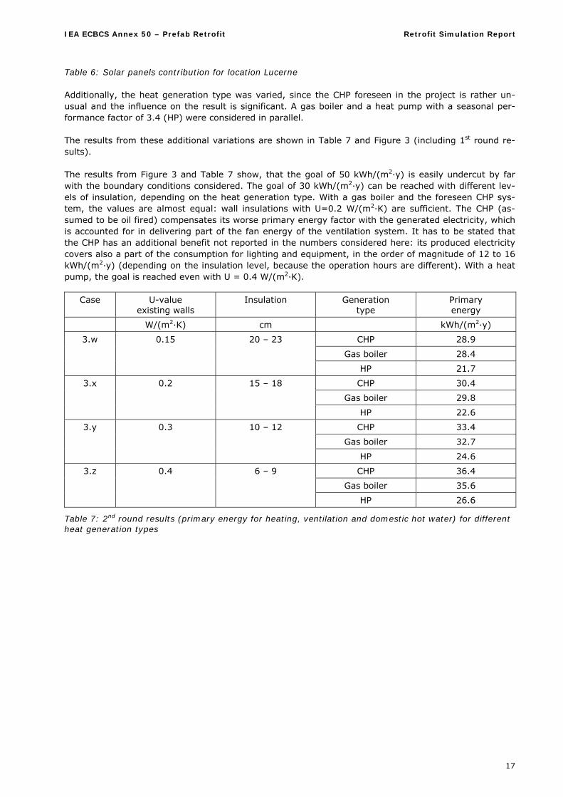
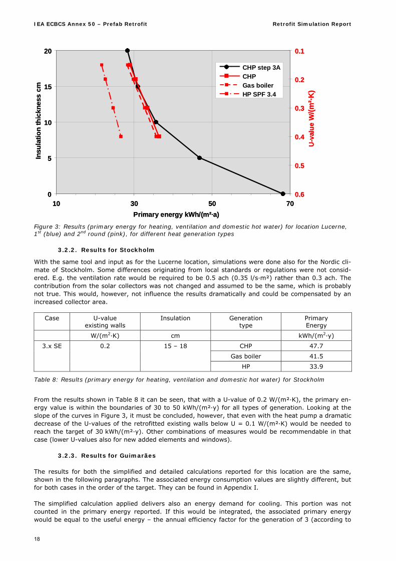
Table 6: Solar panels contribution for location Lucerne Additionally, the heat generation type was varied, since the CHP foreseen in the project is rather un-usual and the influence on the result is significant. A gas boiler and a heat pump with a seasonal per-formance factor of 3.4 (HP) were considered in parallel. The results from these additional variations are shown in Table 7 and Figure 3 (including 1st round re-sults). The results from Figure 3 and Table 7 show, that the goal of 50 kWh/(m2·y) is easily undercut by far with the boundary conditions considered. The goal of 30 kWh/(m2·y) can be reached with different lev-els of insulation, depending on the heat generation type. With a gas boiler and the foreseen CHP sys-tem, the values are almost equal: wall insulations with U=0.2 W/(m2·K) are sufficient. The CHP (as-sumed to be oil fired) compensates its worse primary energy factor with the generated electricity, which is accounted for in delivering part of the fan energy of the ventilation system. It has to be stated that the CHP has an additional benefit not reported in the numbers considered here: its produced electricity covers also a part of the consumption for lighting and equipment, in the order of magnitude of 12 to 16 kWh/(m2·y) (depending on the insulation level, because the operation hours are different). With a heat pump, the goal is reached even with U = 0.4 W/(m2·K).
Case U-value existing walls
Insulation Generation type
Primary energy
W/(m2·K) cm kWh/(m2·y)
CHP 28.9
Gas boiler 28.4
3.w 0.15 20 – 23
HP 21.7
CHP 30.4
Gas boiler 29.8
3.x 0.2 15 – 18
HP 22.6
CHP 33.4
Gas boiler 32.7
3.y 0.3 10 – 12
HP 24.6
CHP 36.4
Gas boiler 35.6
3.z 0.4 6 – 9
HP 26.6
Table 7: 2nd round results (primary energy for heating, ventilation and domestic hot water) for different heat generation types
IEA ECBCS Annex 50 – Prefab Retrofit Retrofit Simulation Report
18
0
5
10
15
20
10 30 50 70
Primary energy kWh/(m²·a)
Insu
lati
on
thic
knes
scm
0.1
0.2
0.3
0.4
0.5
0.6
U-v
alu
eW
/(m
²·K
)
CHP step 3A
CHP
Gas boiler
HP SPF 3.4
0
5
10
15
20
10 30 50 70
Primary energy kWh/(m²·a)
Insu
lati
on
thic
knes
scm
0.1
0.2
0.3
0.4
0.5
0.6
U-v
alu
eW
/(m
²·K
)
CHP step 3A
CHP
Gas boiler
HP SPF 3.4
Figure 3: Results (primary energy for heating, ventilation and domestic hot water) for location Lucerne, 1st (blue) and 2nd round (pink), for different heat generation types
3.2.2. Results for Stockholm
With the same tool and input as for the Lucerne location, simulations were done also for the Nordic cli-mate of Stockholm. Some differences originating from local standards or regulations were not consid-ered. E.g. the ventilation rate would be required to be 0.5 ach (0.35 l/s·m²) rather than 0.3 ach. The contribution from the solar collectors was not changed and assumed to be the same, which is probably not true. This would, however, not influence the results dramatically and could be compensated by an increased collector area.
Case U-value existing walls
Insulation Generation type
Primary Energy
W/(m2·K) cm kWh/(m2·y)
CHP 47.7
Gas boiler 41.5
3.x SE 0.2 15 – 18
HP 33.9
Table 8: Results (primary energy for heating, ventilation and domestic hot water) for Stockholm
From the results shown in Table 8 it can be seen, that with a U-value of 0.2 W/(m²·K), the primary en-ergy value is within the boundaries of 30 to 50 kWh/(m²·y) for all types of generation. Looking at the slope of the curves in Figure 3, it must be concluded, however, that even with the heat pump a dramatic decrease of the U-values of the retrofitted existing walls below U = 0.1 W/(m²·K) would be needed to reach the target of 30 kWh/(m²·y). Other combinations of measures would be recommendable in that case (lower U-values also for new added elements and windows).
3.2.3. Results for Guimarães The results for both the simplified and detailed calculations reported for this location are the same, shown in the following paragraphs. The associated energy consumption values are slightly different, but for both cases in the order of the target. They can be found in Appendix I. The simplified calculation applied delivers also an energy demand for cooling. This portion was not counted in the primary energy reported. If this would be integrated, the associated primary energy would be equal to the useful energy – the annual efficiency factor for the generation of 3 (according to
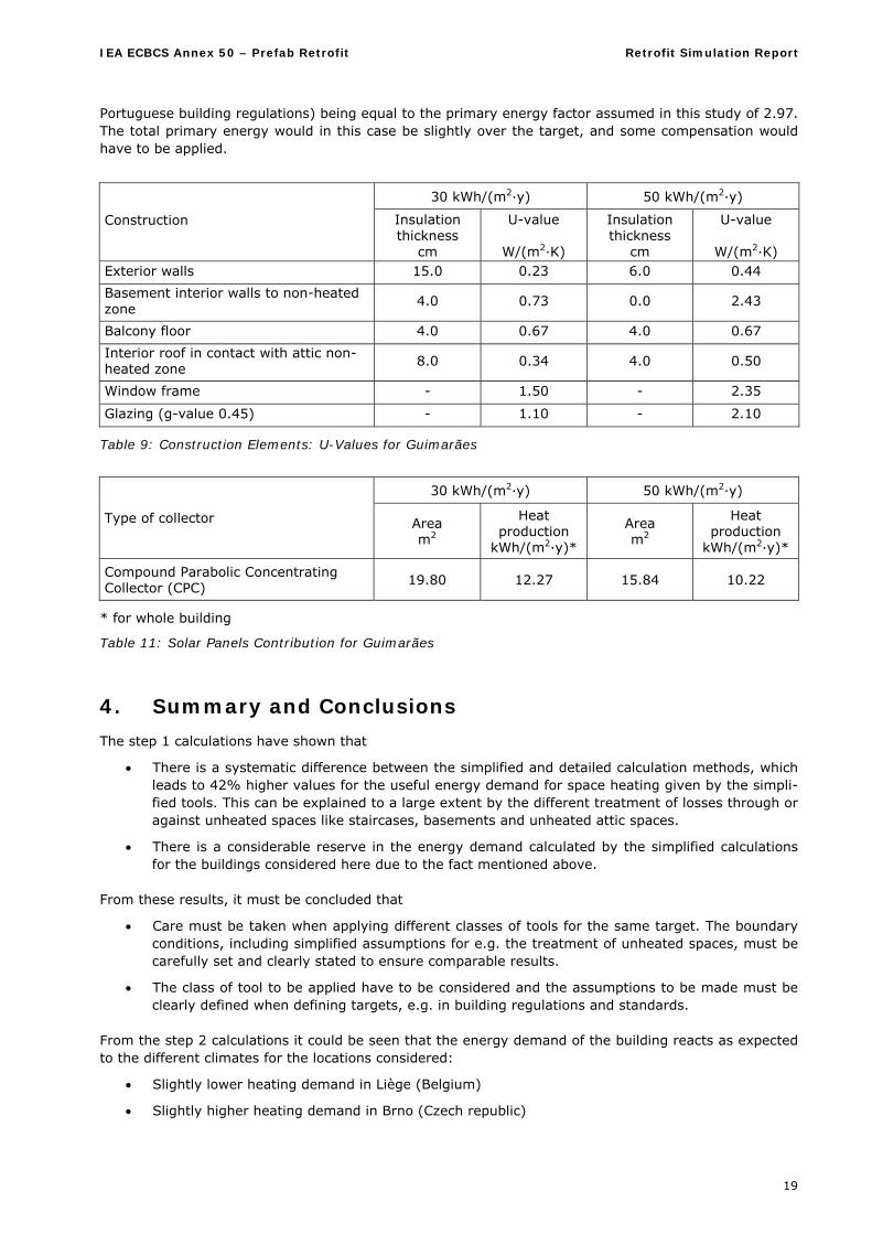
IEA ECBCS Annex 50 – Prefab Retrofit Retrofit Simulation Report
19
Portuguese building regulations) being equal to the primary energy factor assumed in this study of 2.97. The total primary energy would in this case be slightly over the target, and some compensation would have to be applied.
30 kWh/(m2·y) 50 kWh/(m2·y)
Construction Insulation thickness
cm
U-value
W/(m2·K)
Insulation thickness
cm
U-value
W/(m2·K) Exterior walls 15.0 0.23 6.0 0.44
Basement interior walls to non-heated zone
4.0 0.73 0.0 2.43
Balcony floor 4.0 0.67 4.0 0.67
Interior roof in contact with attic non-heated zone
8.0 0.34 4.0 0.50
Window frame - 1.50 - 2.35
Glazing (g-value 0.45) - 1.10 - 2.10
Table 9: Construction Elements: U-Values for Guimarães
30 kWh/(m2·y) 50 kWh/(m2·y)
Type of collector Area m2
Heat production
kWh/(m2·y)*
Area m2
Heat production
kWh/(m2·y)*
Compound Parabolic Concentrating Collector (CPC)
19.80 12.27 15.84 10.22
* for whole building
Table 11: Solar Panels Contribution for Guimarães
4. Summary and Conclusions
The step 1 calculations have shown that
There is a systematic difference between the simplified and detailed calculation methods, which leads to 42% higher values for the useful energy demand for space heating given by the simpli-fied tools. This can be explained to a large extent by the different treatment of losses through or against unheated spaces like staircases, basements and unheated attic spaces.
There is a considerable reserve in the energy demand calculated by the simplified calculations for the buildings considered here due to the fact mentioned above.
From these results, it must be concluded that
Care must be taken when applying different classes of tools for the same target. The boundary conditions, including simplified assumptions for e.g. the treatment of unheated spaces, must be carefully set and clearly stated to ensure comparable results.
The class of tool to be applied have to be considered and the assumptions to be made must be clearly defined when defining targets, e.g. in building regulations and standards.
From the step 2 calculations it could be seen that the energy demand of the building reacts as expected to the different climates for the locations considered:
Slightly lower heating demand in Liège (Belgium)
Slightly higher heating demand in Brno (Czech republic)
IEA ECBCS Annex 50 – Prefab Retrofit Retrofit Simulation Report
20
Considerably lower heating demand and a potential for cooling, if the respective measures are not taken, for the Mediterranean location of Guimarães (Portugal)
The step 3 calculations, being the main step of this study, lead to the necessary building modifications to be applied at the different locations in order to reach the goal of a primary energy consumption for heating, ventilation and domestic hot water consumption of 30 to 50 kWh/(m2·K).
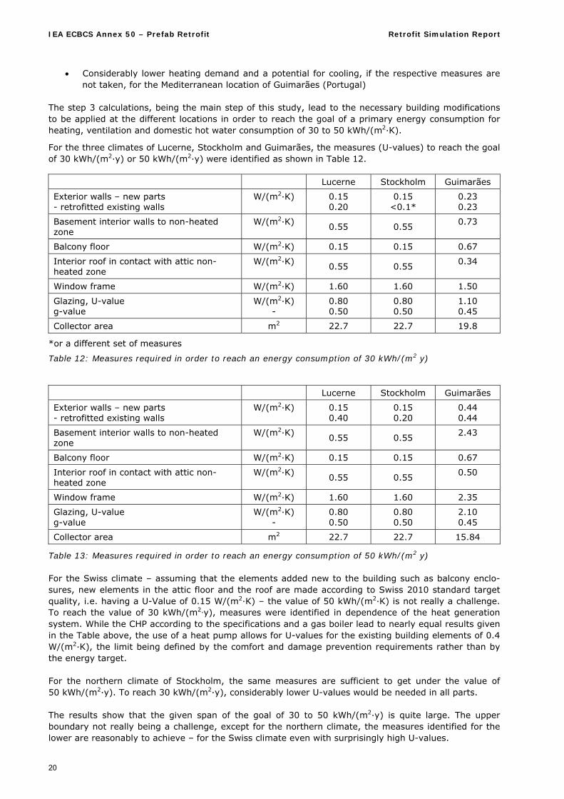
For the three climates of Lucerne, Stockholm and Guimarães, the measures (U-values) to reach the goal of 30 kWh/(m2·y) or 50 kWh/(m2·y) were identified as shown in Table 12. Lucerne Stockholm Guimarães
Exterior walls – new parts - retrofitted existing walls
W/(m2·K) 0.15 0.20
0.15 <0.1*
0.23 0.23
Basement interior walls to non-heated zone
W/(m2·K) 0.55 0.55
0.73
Balcony floor W/(m2·K) 0.15 0.15 0.67
Interior roof in contact with attic non-heated zone
W/(m2·K) 0.55 0.55
0.34
Window frame W/(m2·K) 1.60 1.60 1.50
Glazing, U-value g-value
W/(m2·K) -
0.80 0.50
0.80 0.50
1.10 0.45
Collector area m2 22.7 22.7 19.8
*or a different set of measures
Table 12: Measures required in order to reach an energy consumption of 30 kWh/(m2·y)
Lucerne Stockholm Guimarães
Exterior walls – new parts - retrofitted existing walls
W/(m2·K) 0.15 0.40
0.15 0.20
0.44 0.44
Basement interior walls to non-heated zone
W/(m2·K) 0.55 0.55
2.43
Balcony floor W/(m2·K) 0.15 0.15 0.67
Interior roof in contact with attic non-heated zone
W/(m2·K) 0.55 0.55
0.50
Window frame W/(m2·K) 1.60 1.60 2.35
Glazing, U-value g-value
W/(m2·K) -
0.80 0.50
0.80 0.50
2.10 0.45
Collector area m2 22.7 22.7 15.84
Table 13: Measures required in order to reach an energy consumption of 50 kWh/(m2·y) For the Swiss climate – assuming that the elements added new to the building such as balcony enclo-sures, new elements in the attic floor and the roof are made according to Swiss 2010 standard target quality, i.e. having a U-Value of 0.15 W/(m2·K) – the value of 50 kWh/(m2·K) is not really a challenge. To reach the value of 30 kWh/(m2·y), measures were identified in dependence of the heat generation system. While the CHP according to the specifications and a gas boiler lead to nearly equal results given in the Table above, the use of a heat pump allows for U-values for the existing building elements of 0.4 W/(m2·K), the limit being defined by the comfort and damage prevention requirements rather than by the energy target. For the northern climate of Stockholm, the same measures are sufficient to get under the value of 50 kWh/(m2·y). To reach 30 kWh/(m2·y), considerably lower U-values would be needed in all parts. The results show that the given span of the goal of 30 to 50 kWh/(m2·y) is quite large. The upper boundary not really being a challenge, except for the northern climate, the measures identified for the lower are reasonably to achieve – for the Swiss climate even with surprisingly high U-values.
IEA ECBCS Annex 50 – Prefab Retrofit Retrofit Simulation Report
21
From these results it can be concluded that Setting targets on the level of primary energy for space heating, ventilation and domestic hot
water leads to a strong dependency on the type of heat generation. It must be decided whether this higher degree of freedom is wanted.
It is possible with a reasonable technical effort to achieve a target of 30 kWh/(m²·y) for a wide range of European climates.
5. References Publications within the IEA ECBCS Annex 501:
[I] Mark Zimmermann: ECBCS Project Summary report “Annex 50 Prefabricated Systems for Low Energy Renovation of Residential Buildings, March 2011
[II] Peter Schwehr, Robert Fischer, Sonja Geier: Retrofit Strategies Design Guide, ISBN 978-3-905594-59-1, March 2011
[III] René L. Kobler, Armin Binz, Gregor Steinke, Karl Höfler, Sonja Geier, Johann Aschauer, Stéphane Cousin, Paul Delouche, François Radelet, Bertrand Ruot, Laurent Reynier, Pierre Gobin, Thierry Duforestel, Gérard Senior, Xavier Boulanger, Pedro Silva, Manuela Almeida: Retrofit Module De-sign Guide, ISBN 978-3-905594-60-7, March 2011
[IV] Sonja Geier, Karl Höfler, David Venus, Beat Kämpfen, Reto Miloni, Mark Zimmermann, Chiel Boonstra, Ake Blomsterberg: Building Renovation Case Studies, ISBN 978-3-905594-61-4, March 2011
[V] Mark Zimmermann, Hans Bertschinger, Kurt Christen, Walter Ott, Yvonne Kaufmann, Stefan Carl: Retrofit Advisor, Beta-version, March 2011
[VI] Peter Schwehr, Robert Fischer: Building Typology and Morphology of Swiss Multi-Family Homes 1919 – 1990, January 2010
[VII] Bertrand Ruot: French housing stock built between 1949 and 1974, October 2010
[VIII] Bertrand Ruot: Elements of morphology of collective housing buildings constructed in France be-tween 1949 and 1974, October 2010
[IX] Gerhard Zweifel: Retrofit Simulation Report, March 2011
Further literature:
[1] PEB - CALE2: Belgian calculation tool for energy certification based on EN ISO 13790; http://energie.wallonie.be/fr/outil-de-calcul-ew-pour-les-logements-neufs-cale-version-2-0-valable-jusqu-au-31-decembre-2009.html?IDC=6094&IDD=11074
[2] RCCTE: Portuguese calculation tool for energy certification based on EN ISO 13790; www.rccte.com
[3] Energy+: US Department of Energy Simulation Software; http://apps1.eere.energy.gov/buildings/energyplus/
[4] Bsim 2000: http://www.en.sbi.dk/publications/programs_models/bsim User`s Guide, Kim B. Wittchen, Kjeld Johnsen, Karl Grau, November 2000
[5] IDA-ICE 4.0: Equa Simulation AB, Solna, Sweden; www.equa.se
[6] Standard SIA 380/1 “Thermische Energie im Hochbau”; Swiss Association of Architects and Engi-neers, Zürich, 2009
[7] Standard SIA 180 „Wärme- und Feuchteschutz im Hochbau“, Swiss Association of Architects and Engineers, Zürich, 1999
[8] SIA Merkblatt 2031: “Energieausweis für Gebäude”; Swiss Association of Architects and Engineers, Zürich, 2009
1 Further information at home pages: www.empa-ren.ch/A50.htm, www.ecbcs.org/annexes/annex50.htm
IEA ECBCS Annex 50 – Prefab Retrofit Retrofit Simulation Report, Appendix H
22
Appendix A Step 1 and 2 Specification
1. Location, situation and building part to be considered
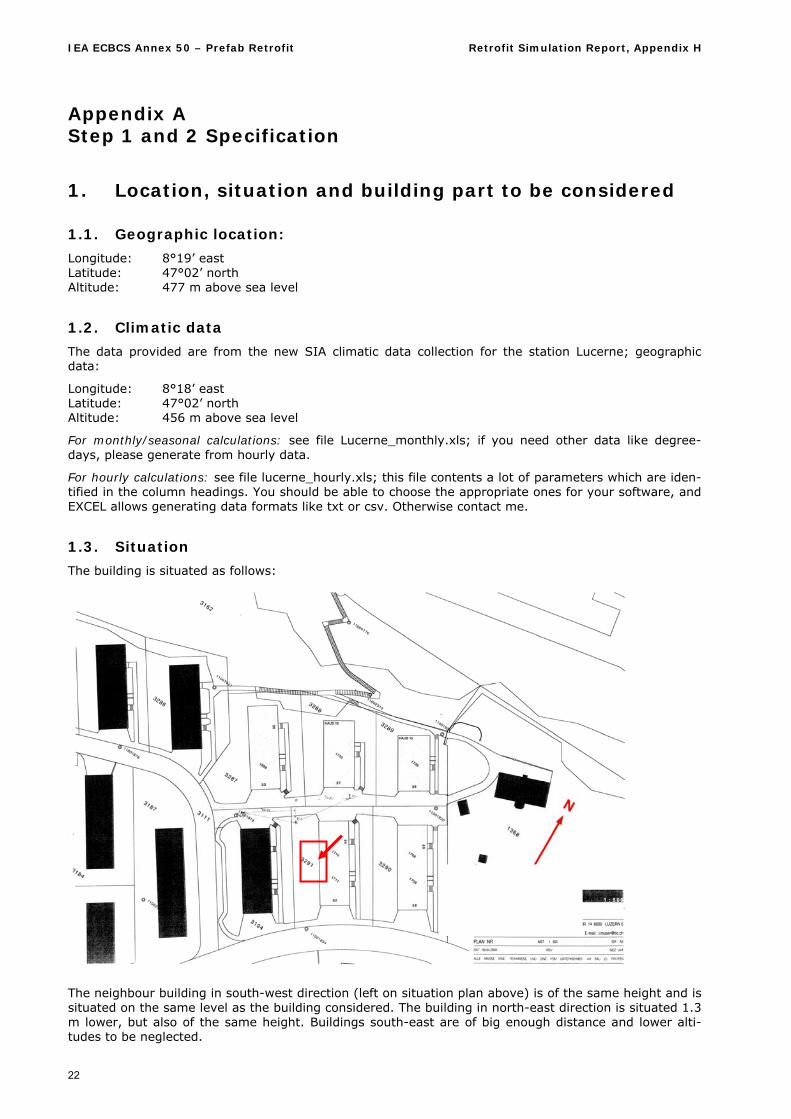
1.1. Geographic location:
Longitude: 8°19’ east Latitude: 47°02’ north Altitude: 477 m above sea level
1.2. Climatic data
The data provided are from the new SIA climatic data collection for the station Lucerne; geographic data:
Longitude: 8°18’ east Latitude: 47°02’ north Altitude: 456 m above sea level
For monthly/seasonal calculations: see file Lucerne_monthly.xls; if you need other data like degree-days, please generate from hourly data.
For hourly calculations: see file lucerne_hourly.xls; this file contents a lot of parameters which are iden-tified in the column headings. You should be able to choose the appropriate ones for your software, and EXCEL allows generating data formats like txt or csv. Otherwise contact me.
1.3. Situation
The building is situated as follows:
The neighbour building in south-west direction (left on situation plan above) is of the same height and is situated on the same level as the building considered. The building in north-east direction is situated 1.3 m lower, but also of the same height. Buildings south-east are of big enough distance and lower alti-tudes to be neglected.

IEA ECBCS Annex 50 – Prefab Retrofit Retrofit Simulation Report, Appendix A
23
2. Building
2.1. General
Building gross heated area: 565 m2 Net used area (staircase excluded): 452 m2 Single room areas can be taken from floor plans.
2.2. Geometry
The building geometry can be taken from the plans enclosed as jpg-Files.
2.2.1. Legend for room names Wohnzimmer living room Zimmer bedroom Küche kitchen Bad bathroom Vorplatz corridor Estrich unheated attic space
2.2.2. Basement
Although in reality there is a central heating room in the basement of our unit, we neglect this and con-sider the whole basement as unheated cellar, also the garages. The south-west wall of the basement is fully in the ground, the north-east side is half to the outside air.
2.2.3. Window sizes
The sizes of the windows without dimensions in the plans are:
Living room south-west: Width: 1.95 m Height: 1.32 m
Bedrooms north-east and south-east: Width: 1.25 m Height: 1.32 m
Bathrooms north-east and south-east: Width: 1.0 m Height: 1.0 m
Skylights in attic kitchens and bathrooms: Width: 0.6 m Height: 0.6 m
2.3. Constructions
2.3.1. Exterior walls All construction layers are given from inside to outside and from top to bottom (for inside ceilings).
Exterior walls 30 cm
Material Thickness Conductivity Density Specific heat cm W/(m·K) kg/m3 J/(kg·K) Plaster finish 1 0.7 1400 1000 Brick masonry 30 0.47 1200 940 Mineral render 1.5 0.87 1800 1000
Exterior walls balcony 25 cm
Material Thickness Conductivity Density Specific heat cm W/(m·K) kg/m3 J/(kg·K) Plaster finish 1 0.7 1400 1000 Brick masonry 12 0.47 1200 940 Cavity 3 0.11* Brick masonry 10 0.47 1200 940 Exterior rendering 1.5 0.87 1800 1000
IEA ECBCS Annex 50 – Prefab Retrofit Retrofit Simulation Report, Appendix H
24
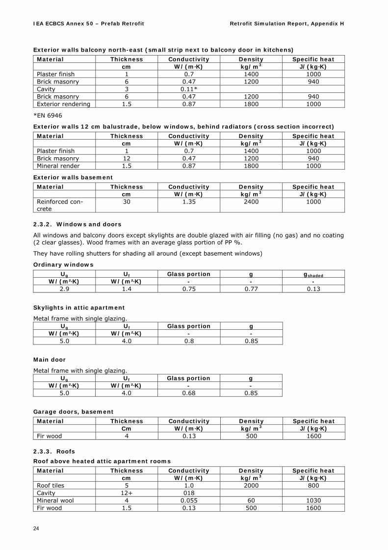
Exterior walls balcony north-east (small strip next to balcony door in kitchens)
Material Thickness Conductivity Density Specific heat cm W/(m·K) kg/m3 J/(kg·K) Plaster finish 1 0.7 1400 1000 Brick masonry 6 0.47 1200 940 Cavity 3 0.11* Brick masonry 6 0.47 1200 940 Exterior rendering 1.5 0.87 1800 1000
*EN 6946
Exterior walls 12 cm balustrade, below windows, behind radiators (cross section incorrect)
Material Thickness Conductivity Density Specific heat cm W/(m·K) kg/m3 J/(kg·K) Plaster finish 1 0.7 1400 1000 Brick masonry 12 0.47 1200 940 Mineral render 1.5 0.87 1800 1000
Exterior walls basement
Material Thickness Conductivity Density Specific heat cm W/(m·K) kg/m3 J/(kg·K) Reinforced con-crete
30 1.35 2400 1000
2.3.2. Windows and doors
All windows and balcony doors except skylights are double glazed with air filling (no gas) and no coating (2 clear glasses). Wood frames with an average glass portion of PP %.
They have rolling shutters for shading all around (except basement windows)
Ordinary windows
Ug Uf Glass portion g gshaded W/(m²·K) W/(m²·K) - - -
2.9 1.4 0.75 0.77 0.13
Skylights in attic apartment
Metal frame with single glazing. Ug Uf Glass portion g
W/(m²·K) W/(m²·K) - - 5.0 4.0 0.8 0.85
Main door
Metal frame with single glazing. Ug Uf Glass portion g
W/(m²·K) W/(m²·K) - - 5.0 4.0 0.68 0.85
Garage doors, basement
Material Thickness Conductivity Density Specific heat Cm W/(m·K) kg/m3 J/(kg·K) Fir wood 4 0.13 500 1600
2.3.3. Roofs
Roof above heated attic apartment rooms
Material Thickness Conductivity Density Specific heat cm W/(m·K) kg/m3 J/(kg·K) Roof tiles 5 1.0 2000 800 Cavity 12+ 018 Mineral wool 4 0.055 60 1030 Fir wood 1.5 0.13 500 1600
IEA ECBCS Annex 50 – Prefab Retrofit Retrofit Simulation Report, Appendix A
25
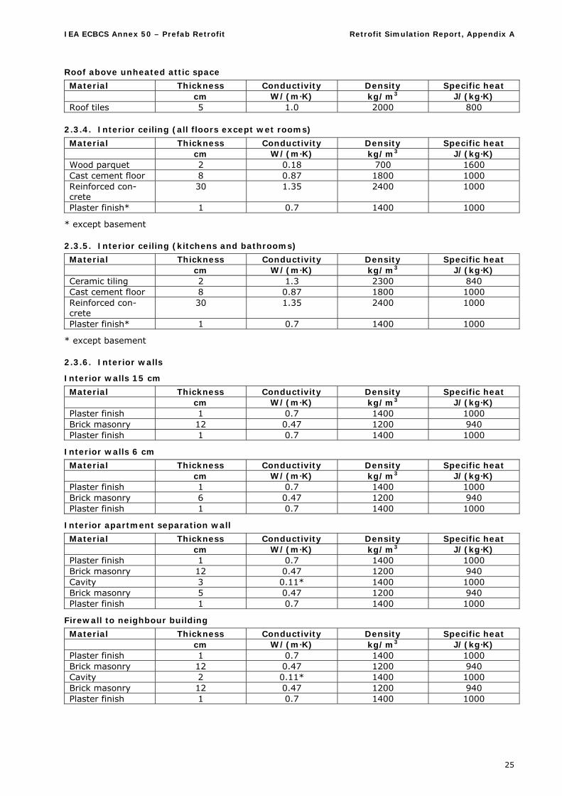
Roof above unheated attic space
Material Thickness Conductivity Density Specific heat cm W/(m·K) kg/m3 J/(kg·K) Roof tiles 5 1.0 2000 800
2.3.4. Interior ceiling (all floors except wet rooms)
Material Thickness Conductivity Density Specific heat cm W/(m·K) kg/m3 J/(kg·K) Wood parquet 2 0.18 700 1600 Cast cement floor 8 0.87 1800 1000 Reinforced con-crete
30 1.35 2400 1000
Plaster finish* 1 0.7 1400 1000
* except basement
2.3.5. Interior ceiling (kitchens and bathrooms)
Material Thickness Conductivity Density Specific heat cm W/(m·K) kg/m3 J/(kg·K) Ceramic tiling 2 1.3 2300 840 Cast cement floor 8 0.87 1800 1000 Reinforced con-crete
30 1.35 2400 1000
Plaster finish* 1 0.7 1400 1000
* except basement
2.3.6. Interior walls
Interior walls 15 cm
Material Thickness Conductivity Density Specific heat cm W/(m·K) kg/m3 J/(kg·K) Plaster finish 1 0.7 1400 1000 Brick masonry 12 0.47 1200 940 Plaster finish 1 0.7 1400 1000
Interior walls 6 cm
Material Thickness Conductivity Density Specific heat cm W/(m·K) kg/m3 J/(kg·K) Plaster finish 1 0.7 1400 1000 Brick masonry 6 0.47 1200 940 Plaster finish 1 0.7 1400 1000
Interior apartment separation wall
Material Thickness Conductivity Density Specific heat cm W/(m·K) kg/m3 J/(kg·K) Plaster finish 1 0.7 1400 1000 Brick masonry 12 0.47 1200 940 Cavity 3 0.11* 1400 1000 Brick masonry 5 0.47 1200 940 Plaster finish 1 0.7 1400 1000
Firewall to neighbour building
Material Thickness Conductivity Density Specific heat cm W/(m·K) kg/m3 J/(kg·K) Plaster finish 1 0.7 1400 1000 Brick masonry 12 0.47 1200 940 Cavity 2 0.11* 1400 1000 Brick masonry 12 0.47 1200 940 Plaster finish 1 0.7 1400 1000

IEA ECBCS Annex 50 – Prefab Retrofit Retrofit Simulation Report, Appendix H
26
Attic apartment interior walls
All walls are brick masonry with plaster finish, values as above. Please take thicknesses from floor plan.
Basement central interior wall
Material Thickness Conductivity Density Specific heat cm W/(m·K) kg/m3 J/(kg·K) Reinforced con-crete
25 1.35 2400 1000
Basement interior separation walls
Material Thickness Conductivity Density Specific heat cm W/(m·K) kg/m3 J/(kg·K) Cement brick ma-sonry
15 1.1 2000 900
Neglect all thinner separation walls.
2.3.7. Thermal bridges
Wall/ceiling joint
All concrete ceilings penetrate completely the exterior walls and are only covered by the mineral render layer.
Balconies
The ceilings are lead through and form the balconies, no thermal separation. But in the balcony area they are thinner or tapered, respectively.
Window-wall connection
All windows are fixed on the inside of the outer brick layer or to an edge brick of 12 cm depth.
Roller blind cases
Above all windows there is a case for the roller blinds, up to the ceiling and over the whole window width. Inside cover is a 2 cm wood board, outside there is a 6 cm brick layer, but the cases are not closed from the bottom.
2.3.8. Air tightness, infiltration and ventilation
An air exchange rate of 0.3 h-1 shall be applied for the untightness of the building shell.
The hygienic ventilation rate is 30 m3/(h·person) at daytime and 15 m3/(h·person) at night time, but when the above untightness value is bigger, this shall be applied.
There are no mechanical ventilation systems (cooking hoods neglected).
3. Building Use
3.1. Occupation
Occupation density: 32 m2 net area/person (also if uneven person numbers result)
Metabolic rate: 1.2 met
Heat emission 70 W/person (sensible)
Humidity emission 80 g/h person
Average presence time per day (for monthly/seasonal calculations): 12 h
Daily schedule (for hourly calculations):
Hour 1 2 3 4 5 6 7 8 9 10 11 12 13 14 15 16 17 18 19 20 21 22 23 24Value 1.0 1.0 1.0 1.0 1.0 1.0 0.8 0.6 0.4 0.4 0.4 0.6 0.8 0.6 0.4 0.4 0.6 0.8 0.8 0.8 0.8 1.0 1.0 1.0
IEA ECBCS Annex 50 – Prefab Retrofit Retrofit Simulation Report, Appendix A
27
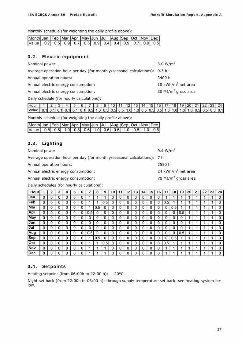
Monthly schedule (for weighting the daily profile above):
Month Jan Feb Mar Apr May Jun Jul Aug Sep Oct Nov DecValue 0.7 0.5 0.9 0.7 0.5 0.9 0.4 0.4 0.9 0.7 0.9 0.5
3.2. Electric equipment
Nominal power: 3.0 W/m2
Average operation hour per day (for monthly/seasonal calculations): 9.3 h
Annual operation hours: 3400 h
Annual electric energy consumption: 10 kWh/m2 net area
Annual electric energy consumption: 30 MJ/m2 gross area
Daily schedule (for hourly calculations):
Hour 1 2 3 4 5 6 7 8 9 10 11 12 13 14 15 16 17 18 19 20 21 22 23 24Value 0.1 0.1 0.1 0.1 0.1 0.1 0.5 1.0 0.5 0.5 0.5 1.0 1.0 0.5 0.5 0.5 1.0 1.0 1.0 1.0 0.5 0.5 0.5 0.1
Monthly schedule (for weighting the daily profile above):
Month Jan Feb Mar Apr May Jun Jul Aug Sep Oct Nov DecValue 0.8 0.6 1.0 0.8 0.6 1.0 0.6 0.6 1.0 0.8 1.0 0.6
3.3. Lighting
Nominal power: 9.4 W/m2
Average operation hour per day (for monthly/seasonal calculations): 7 h
Annual operation hours: 2550 h
Annual electric energy consumption: 24 kWh/m2 net area
Annual electric energy consumption: 70 MJ/m2 gross area
Daily schedules (for hourly calculations):
Hour 1 2 3 4 5 6 7 8 9 10 11 12 13 14 15 16 17 18 19 20 21 22 23 24Jan 0 0 0 0 0 0 1 1 1 0 0 0 0 0 0 0 1 1 1 1 1 1 1 0Feb 0 0 0 0 0 0 1 1 0.5 0 0 0 0 0 0 0 0.5 1 1 1 1 1 1 0Mar 0 0 0 0 0 0 1 0.5 0 0 0 0 0 0 0 0 0 0.5 1 1 1 1 1 0Apr 0 0 0 0 0 0 0.5 0 0 0 0 0 0 0 0 0 0 0 0.5 1 1 1 1 0May 0 0 0 0 0 0 0 0 0 0 0 0 0 0 0 0 0 0 0 1 1 1 1 0Jun 0 0 0 0 0 0 0 0 0 0 0 0 0 0 0 0 0 0 0 1 1 1 1 0Jul 0 0 0 0 0 0 0 0 0 0 0 0 0 0 0 0 0 0 0 1 1 1 1 0Aug 0 0 0 0 0 0 0.5 0 0 0 0 0 0 0 0 0 0 0 0.5 1 1 1 1 0Sep 0 0 0 0 0 0 1 0.5 0 0 0 0 0 0 0 0 0 0.5 1 1 1 1 1 0Oct 0 0 0 0 0 0 1 1 0.5 0 0 0 0 0 0 0 0.5 1 1 1 1 1 1 0Nov 0 0 0 0 0 0 1 1 1 0 0 0 0 0 0 0 1 1 1 1 1 1 1 0Dec 0 0 0 0 0 0 1 1 1 0 0 0 0 0 0 0 1 1 1 1 1 1 1 0
3.4. Setpoints
Heating setpoint (from 06:00h to 22:00 h): 20°C
Night set back (from 22:00h to 06:00 h): through supply temperature set back, see heating system be-low.
IEA ECBCS Annex 50 – Prefab Retrofit Retrofit Simulation Report, Appendix H
28
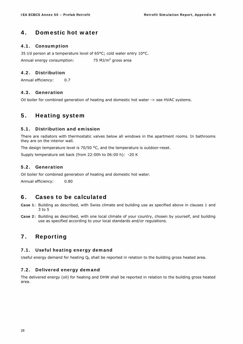
4. Domestic hot water
4.1. Consumption
35 l/d person at a temperature level of 65°C; cold water entry 10°C.
Annual energy consumption: 75 MJ/m2 gross area
4.2. Distribution
Annual efficiency: 0.7
4.3. Generation
Oil boiler for combined generation of heating and domestic hot water -> see HVAC systems.
5. Heating system
5.1. Distribution and emission
There are radiators with thermostatic valves below all windows in the apartment rooms. In bathrooms they are on the interior wall.
The design temperature level is 70/50 °C, and the temperature is outdoor-reset.
Supply temperature set back (from 22:00h to 06:00 h): -20 K
5.2. Generation
Oil boiler for combined generation of heating and domestic hot water.
Annual efficiency: 0.80
6. Cases to be calculated Case 1: Building as described, with Swiss climate and building use as specified above in clauses 1 and
3 to 5
Case 2: Building as described, with one local climate of your country, chosen by yourself, and building use as specified according to your local standards and/or regulations.
7. Reporting
7.1. Useful heating energy demand
Useful energy demand for heating Qh shall be reported in relation to the building gross heated area.
7.2. Delivered energy demand
The delivered energy (oil) for heating and DHW shall be reported in relation to the building gross heated area.
IEA ECBCS Annex 50 – Prefab Retrofit Retrofit Simulation Report, Appendix A
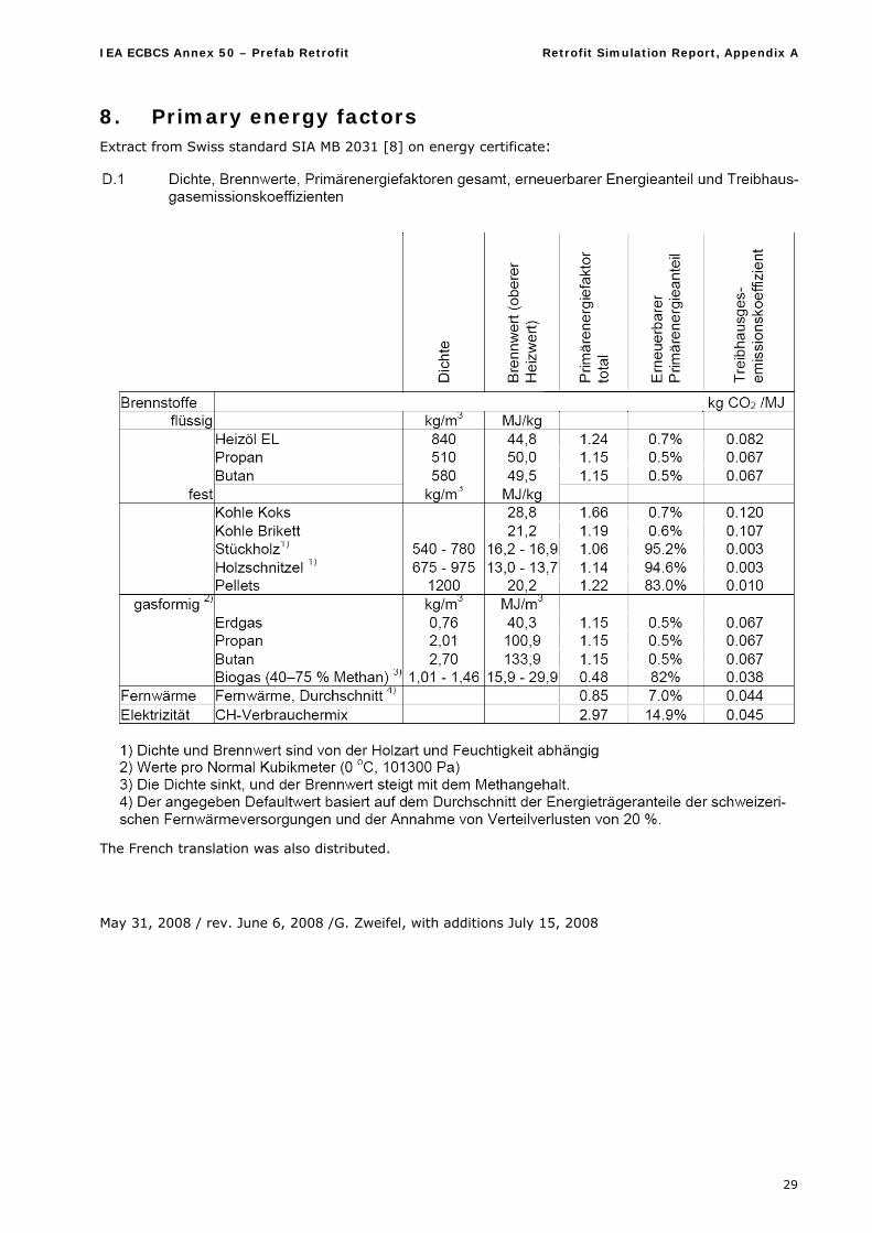
29
8. Primary energy factors Extract from Swiss standard SIA MB 2031 [8] on energy certificate:
The French translation was also distributed.
May 31, 2008 / rev. June 6, 2008 /G. Zweifel, with additions July 15, 2008
IEA ECBCS Annex 50 – Prefab Retrofit Retrofit Simulation Report, Appendix B
30
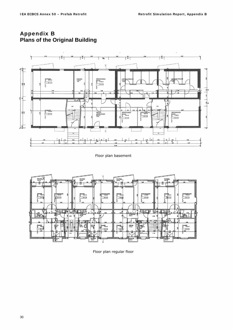
Appendix B Plans of the Original Building
Floor plan basement
Floor plan regular floor
IEA ECBCS Annex 50 – Prefab Retrofit Retrofit Simulation Report, Appendix B
31
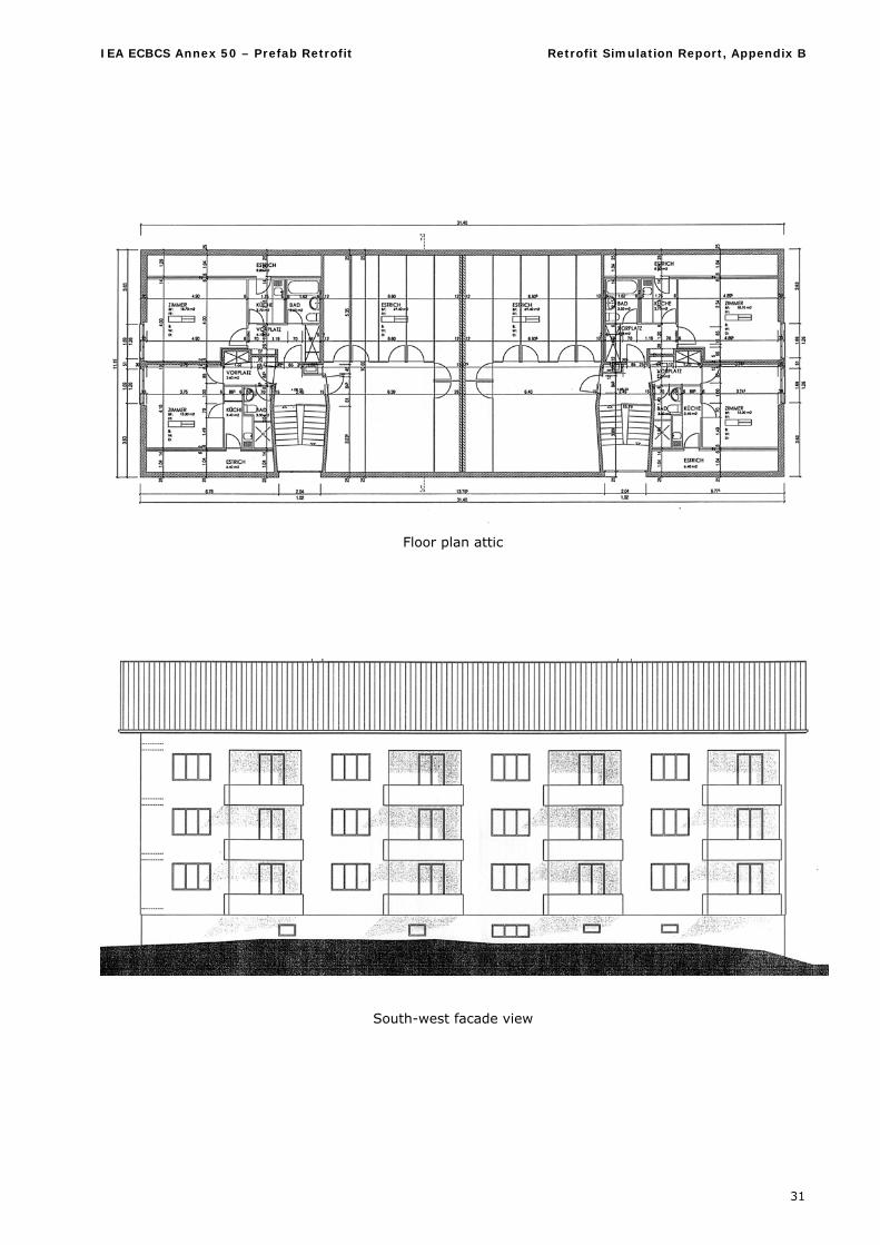
Floor plan attic
South-west facade view
IEA ECBCS Annex 50 – Prefab Retrofit Retrofit Simulation Report, Appendix B
32
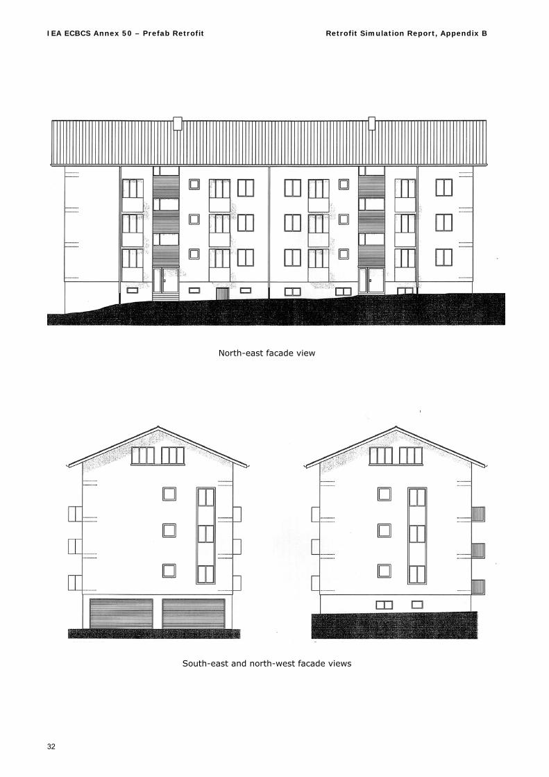
North-east facade view
South-east and north-west facade views
IEA ECBCS Annex 50 – Prefab Retrofit Retrofit Simulation Report, Appendix C
33
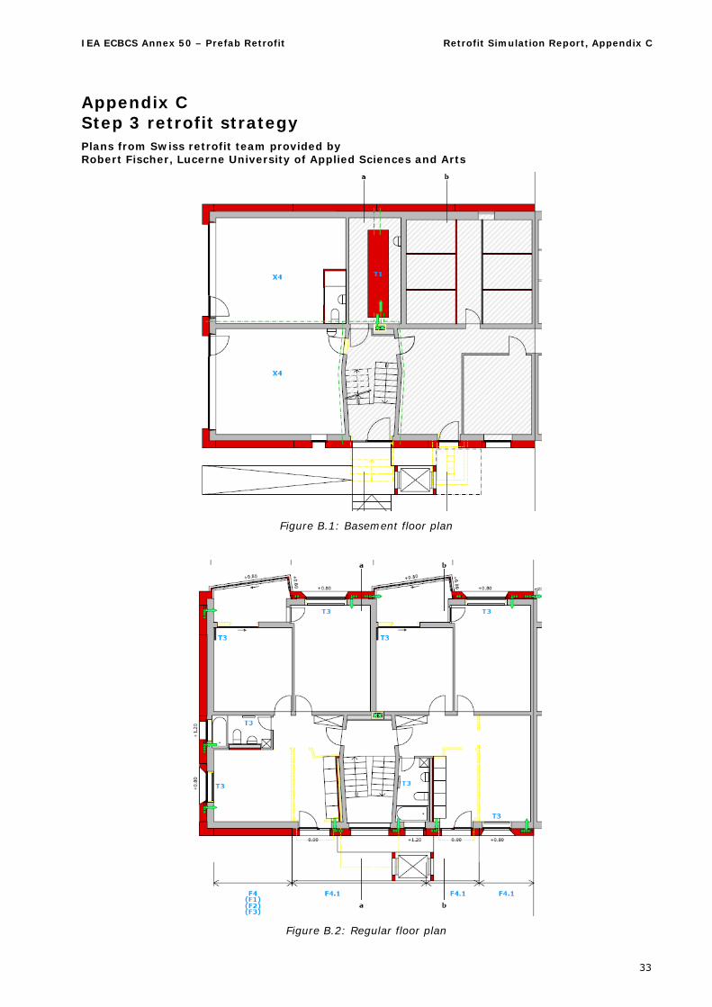
Appendix C Step 3 retrofit strategy Plans from Swiss retrofit team provided by Robert Fischer, Lucerne University of Applied Sciences and Arts
Figure B.1: Basement floor plan
Figure B.2: Regular floor plan
IEA ECBCS Annex 50 – Prefab Retrofit Retrofit Simulation Report, Appendix C
34
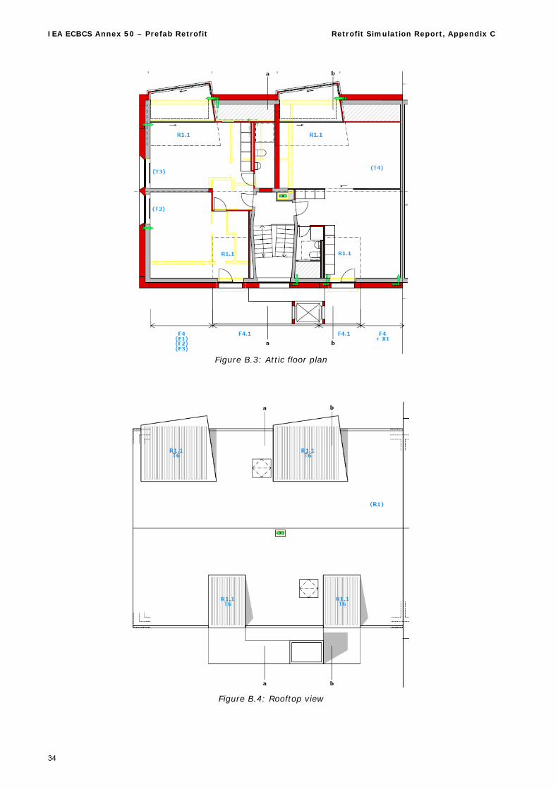
Figure B.3: Attic floor plan
Figure B.4: Rooftop view
IEA ECBCS Annex 50 – Prefab Retrofit Retrofit Simulation Report, Appendix C
35
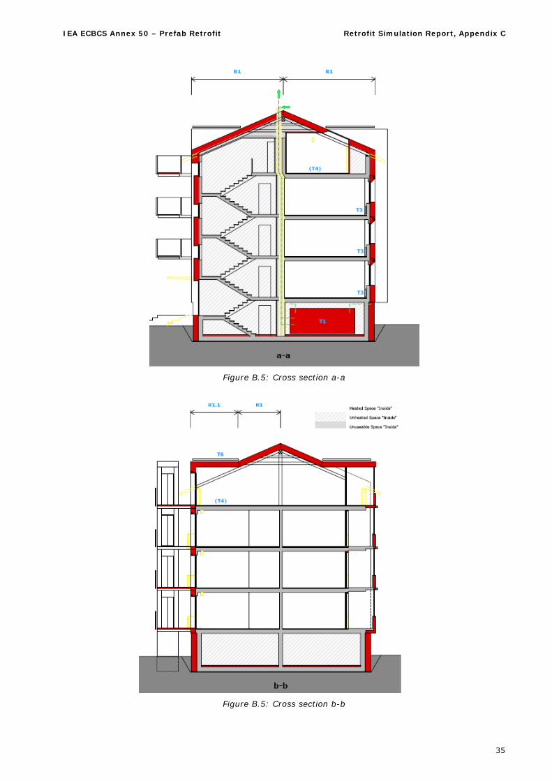
Figure B.5: Cross section a-a
Figure B.5: Cross section b-b
IEA ECBCS Annex 50 – Prefab Retrofit Retrofit Simulation Report, Appendix D
36
Appendix D Step 3 Retrofit Case - Specification
1. Building Changes
1.1. Principal changes
The principal changes at the building are
Addition of an access addition on the NE-side, consisting of a lift tower and access balconies on the floors 2 to 5.
Inclusion of the former garages in the basement as multi purpose heated spaces, with direct ac-cess from outside (or from the stair case, 1 room)
Inclusion of the former balconies on the south-west façade in the heated space by putting a new facade around. No new balconies on this side
Addition of modules with flat roof in limited areas on the attic floor
1.2. Geometry
The building geometry can be taken from the plans in Appendix C.
1.2.1. Added floor area
Due to added space areas in the attic and the basement and the inclusion of the balconies, the floor ar-eas are considerably bigger. The gross heated area given does not include the added construction thick-ness.
Building gross heated area: 782.5 m2 Net used area (staircase excluded): 635 m2
Another area depending on the added construction thickness adds to the gross heated area:
Added area = Perimeter length x added thickness.
The perimeter length is 158 m.
1.2.2. NE-Access addition
The lift tower can be seen in the b-b cut and in the floor plans level 2 to 4. On level 2 there is no access balcony for the left hand flat (seen from stair case entry) because there is the ramp.
The balconies have semi transparent balustrades.
1.2.3. Basement
The two new rooms are the size of the former garages. Their opening on the SE-side can be assumed to be of the size of the former garage doors. The rest of the basement (shaded area) is left as unheated space but despite included in the insulation perimeter.
1.2.4. SW-Balconies
The new walls around the former balconies are glazed from the top of the former balustrade to the bot-tom of the next floor. The balustrades are insulated. This is the case for the whole perimeter of the bal-conies.
Part of the former exterior wall and the balustrade below the window towards the balconies are removed and replaced by a sliding door.
1.2.5. Attic floor
Four new modules are added to the attic floor. They are indicated by the dot-and-dash lines. On the SW side they follow the shape of the balconies below.
Except for a few small areas (shaded) there are no unheated rooms on the attic floor.
IEA ECBCS Annex 50 – Prefab Retrofit Retrofit Simulation Report, Appendix D
37
1.2.6. Window sizes
The sizes of the windows are taken from the existing geometry, except for the new access doors on the NE side which are wider than the balcony doors before, including also the small strip aside which had a special construction before.
1.3. Constructions
1.3.1. Exterior walls
Insulation is added to the existing walls where there are no changes. The thickness is one of the pa-rameters to be figured out by the calculation
The new modules in the attic space are prefabricated wood frame construction with appropriate insula-tion, including the roof. The inside layer is plasterboard.
1.3.2. Roof
The sloped roof is replaced and will have an appropriate insulation layer. The inside finish can be as-sumed to be plaster board.
1.3.3. Air tightness and infiltration
The building will have an air tightness according to an n50 value of 1.0. An according air exchange rate of shall be applied for the untightness of the building shell.
The hygienic ventilation is provided by mechanical ventilation (see below).
2. Building Use The same building use shall be applied as for the step 2 calculations, adjusted to the new floor area.
3. Domestic hot water
3.1. Consumption
Same value as step 2
3.2. Distribution
Annual efficiency: 0.9
3.3. Generation
The generation of the DHW shall have a solar contribution. The new flat roof parts are foreseen for this, using vacuum tube collectors mounted flat on the roof. Building permission problems are one reason for this, therefore this may not be the solution for your countries case.
The solar contribution shall follow the possibilities of the country’s climate and regulations.
4. Ventilation system A central mechanical ventilation system is added, with the air handling unit in the basement and sup-ply/return ducts in the insulation layer of the new façade. It has a heat recovery with an annual effi-ciency of 0.8.
5. Heating system
5.1. Distribution and emission
There are radiators will remain in use, but will be operated on a lower temperature according to the new building shell.
IEA ECBCS Annex 50 – Prefab Retrofit Retrofit Simulation Report, Appendix D
38
5.2. Generation
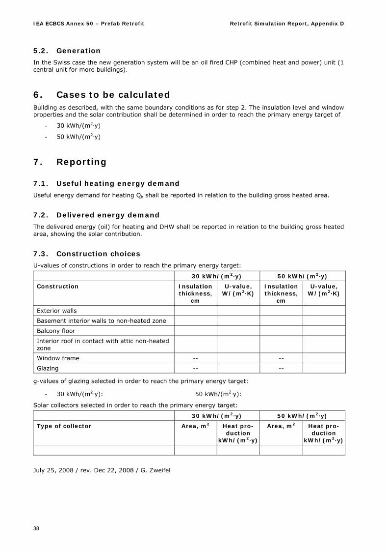
In the Swiss case the new generation system will be an oil fired CHP (combined heat and power) unit (1 central unit for more buildings).
6. Cases to be calculated Building as described, with the same boundary conditions as for step 2. The insulation level and window properties and the solar contribution shall be determined in order to reach the primary energy target of
- 30 kWh/(m2·y)
- 50 kWh/(m2·y)
7. Reporting
7.1. Useful heating energy demand
Useful energy demand for heating Qh shall be reported in relation to the building gross heated area.
7.2. Delivered energy demand
The delivered energy (oil) for heating and DHW shall be reported in relation to the building gross heated area, showing the solar contribution.
7.3. Construction choices
U-values of constructions in order to reach the primary energy target:
30 kWh/(m2·y) 50 kWh/(m2·y)
Construction Insulation thickness,
cm
U-value, W/(m2·K)
Insulation thickness,
cm
U-value, W/(m2·K)
Exterior walls
Basement interior walls to non-heated zone
Balcony floor
Interior roof in contact with attic non-heated zone
Window frame -- --
Glazing -- --
g-values of glazing selected in order to reach the primary energy target:
- 30 kWh/(m2·y): 50 kWh/(m2·y):
Solar collectors selected in order to reach the primary energy target:
30 kWh/(m2·y) 50 kWh/(m2·y)
Type of collector Area, m2 Heat pro-duction
kWh/(m2·y)
Area, m2 Heat pro-duction
kWh/(m2·y)
July 25, 2008 / rev. Dec 22, 2008 / G. Zweifel
IEA ECBCS Annex 50 – Prefab Retrofit Retrofit Simulation Report, Appendix E
39
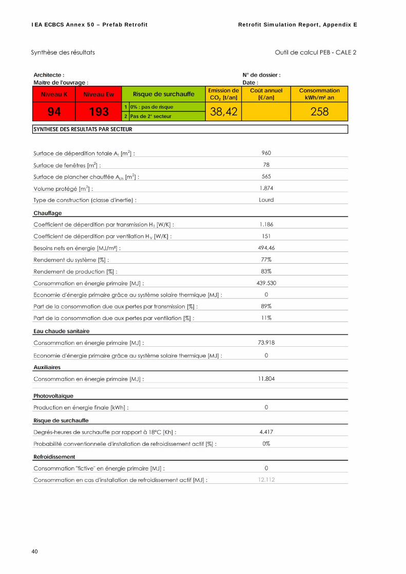
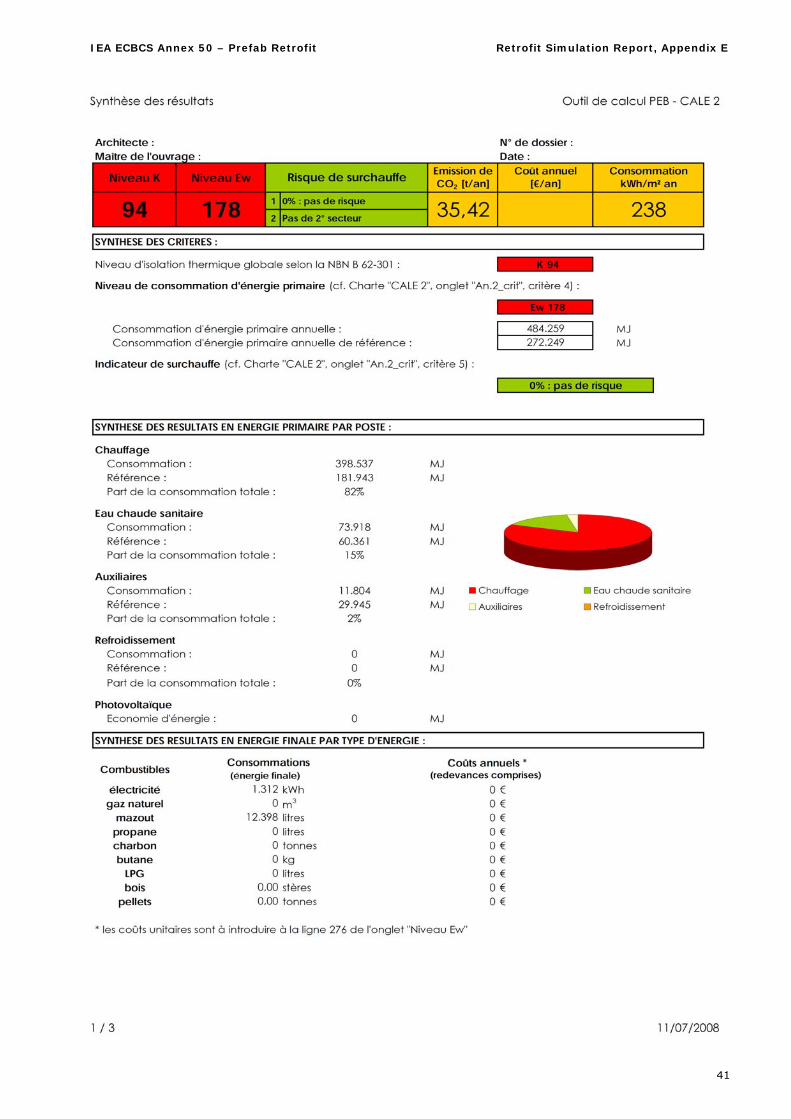
Appendix E Step 1 and 2 Calculation Reports for Simplified Calculations
1. University of Liège
IEA ECBCS Annex 50 – Prefab Retrofit Retrofit Simulation Report, Appendix E
40
IEA ECBCS Annex 50 – Prefab Retrofit Retrofit Simulation Report, Appendix E
41
IEA ECBCS Annex 50 – Prefab Retrofit Retrofit Simulation Report, Appendix E
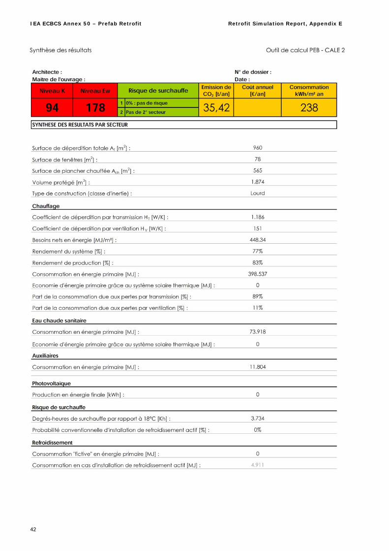
42
IEA ECBCS Annex 50 – Prefab Retrofit Retrofit Simulation Report, Appendix E
43
Additional hypotheses
1. Number of persons living in this part of the building : 14
2. Air exchange rate : 0.3 h-1 → (0.3*V)/Sheated = (0.3*1874)/959.9 = 0.6 m³/(m²·h)
3. U value: cf. attached file
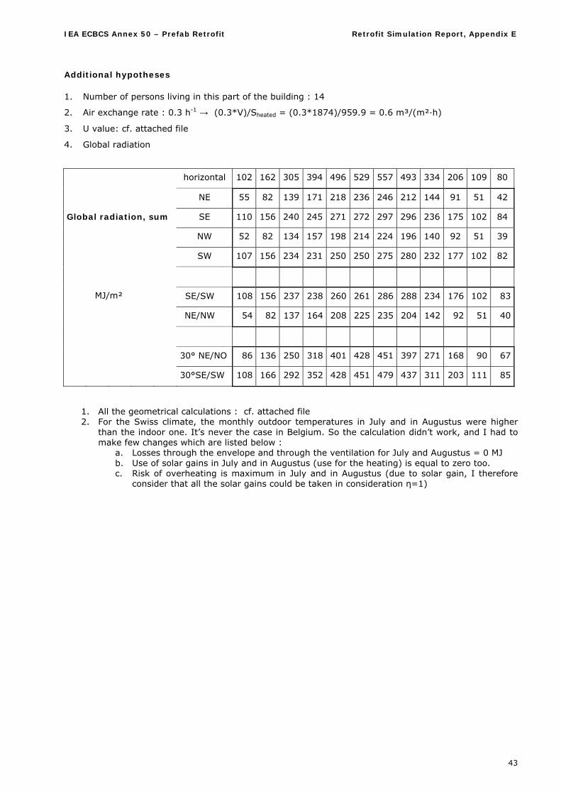
4. Global radiation
horizontal 102 162 305 394 496 529 557 493 334 206 109 80
NE 55 82 139 171 218 236 246 212 144 91 51 42
Global radiation, sum SE 110 156 240 245 271 272 297 296 236 175 102 84
NW 52 82 134 157 198 214 224 196 140 92 51 39
SW 107 156 234 231 250 250 275 280 232 177 102 82
SE/SW 108 156 237 238 260 261 286 288 234 176 102 83
NE/NW 54 82 137 164 208 225 235 204 142 92 51 40
MJ/m²
30° NE/NO 86 136 250 318 401 428 451 397 271 168 90 67
30°SE/SW 108 166 292 352 428 451 479 437 311 203 111 85
1. All the geometrical calculations : cf. attached file 2. For the Swiss climate, the monthly outdoor temperatures in July and in Augustus were higher
than the indoor one. It’s never the case in Belgium. So the calculation didn’t work, and I had to make few changes which are listed below :
a. Losses through the envelope and through the ventilation for July and Augustus = 0 MJ b. Use of solar gains in July and in Augustus (use for the heating) is equal to zero too. c. Risk of overheating is maximum in July and in Augustus (due to solar gain, I therefore
consider that all the solar gains could be taken in consideration η=1)
IEA ECBCS Annex 50 – Prefab Retrofit Retrofit Simulation Report, Appendix E
44
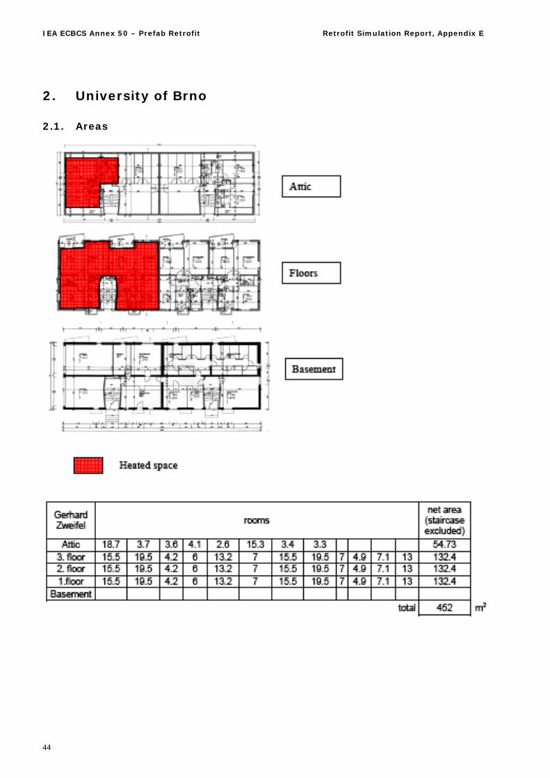
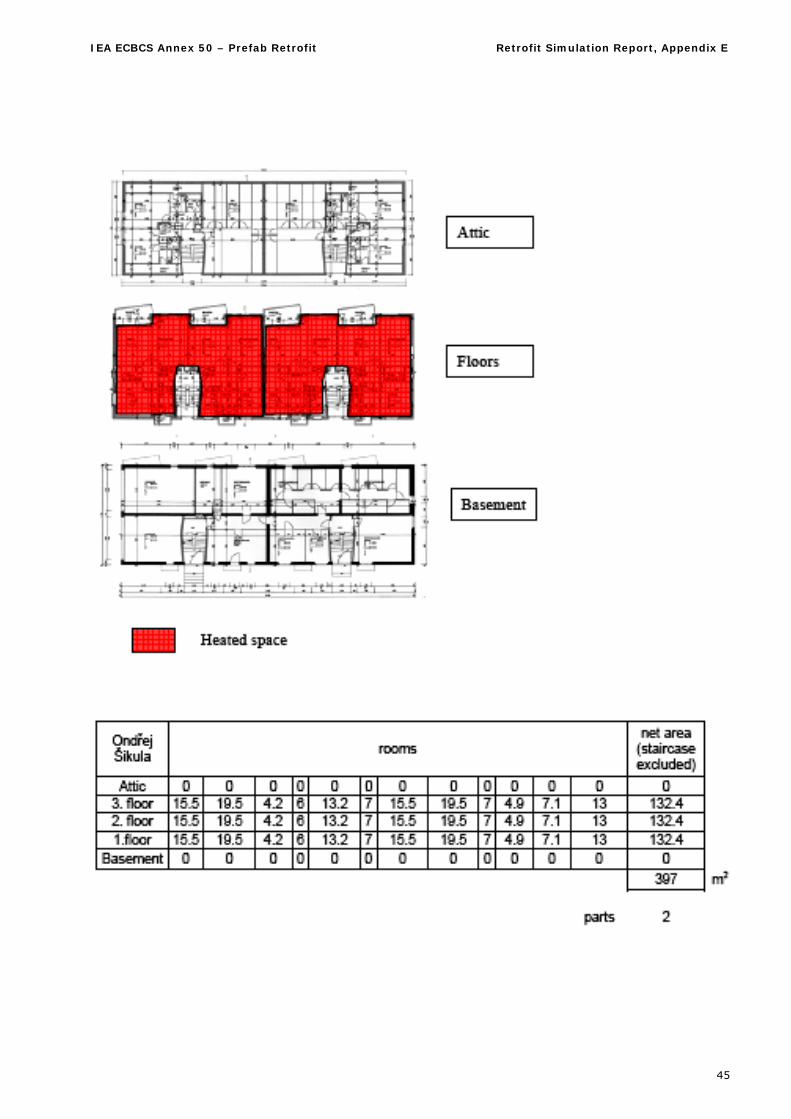
2. University of Brno
2.1. Areas
IEA ECBCS Annex 50 – Prefab Retrofit Retrofit Simulation Report, Appendix E
45
IEA ECBCS Annex 50 – Prefab Retrofit Retrofit Simulation Report, Appendix E
46
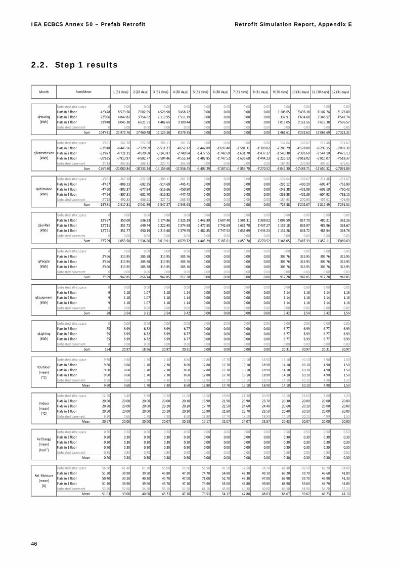
2.2. Step 1 results
Month 1 (31 days) 2 (28 days) 3 (31 days) 4 (30 days) 5 (31 days) 6 (30 days) 7 (31 days) 8 (31 days) 9 (30 days) 10 (31 days) 11 (30 days) 12 (31 days)
Unheated attic space 0 0.00 0.00 0.00 0.00 0.00 0.00 0.00 0.00 0.00 0.00 0.00 0.00
Flats in 3 floor 42'478 8'579.56 7'082.95 4'526.98 3'458.72 0.00 0.00 0.00 0.00 1'108.65 3'436.38 6'107.74 8'177.00
Flats in 2 floor 22'096 4'847.82 3'756.02 2'113.95 1'511.19 0.00 0.00 0.00 0.00 337.91 1'634.68 3'346.57 4'547.74
Flats in 1 floor 39'848 8'045.38 6'621.51 4'482.65 3'309.44 0.00 0.00 0.00 0.00 1'015.05 3'161.56 5'615.38 7'596.57
Unheated basement 0 0.00 0.00 0.00 0.00 0.00 0.00 0.00 0.00 0.00 0.00 0.00 0.00
Sum 104'421 21'472.76 17'460.48 11'123.58 8'279.35 0.00 0.00 0.00 0.00 2'461.61 8'232.62 15'069.69 20'321.31
Unheated attic space 1'661 267.38 222.98 206.11 201.75 0.00 0.00 0.00 0.00 132.64 166.67 211.48 251.67
Flats in 3 floor ‐52'918 ‐8'445.56 ‐7'329.69 ‐5'511.27 ‐4'652.17 ‐1'442.89 ‐1'697.40 ‐1'591.31 ‐1'389.02 ‐2'286.79 ‐4'178.00 ‐6'296.15 ‐8'097.39
Flats in 2 floor ‐32'877 ‐4'721.31 ‐4'020.68 ‐3'143.87 ‐2'749.04 ‐1'477.55 ‐1'742.69 ‐1'631.70 ‐1'437.27 ‐1'540.38 ‐2'393.69 ‐3'544.10 ‐4'475.13
Flats in 1 floor ‐50'635 ‐7'913.97 ‐6'882.77 ‐5'504.46 ‐4'555.24 ‐1'482.85 ‐1'747.52 ‐1'636.69 ‐1'444.23 ‐2'220.13 ‐3'918.02 ‐5'810.07 ‐7'519.37
Unheated basement 2'713 492.83 386.11 227.71 265.98 0.00 0.00 0.00 0.00 184.93 270.90 407.61 476.65
Sum ‐136'430 ‐21'080.84 ‐18'233.14 ‐14'159.60 ‐11'956.45 ‐4'403.29 ‐5'187.61 ‐4'859.70 ‐4'270.52 ‐6'047.30 ‐10'489.71 ‐15'650.32 ‐20'091.89
Unheated attic space ‐1'661 ‐267.38 ‐222.98 ‐206.11 ‐201.75 0.00 0.00 0.00 0.00 ‐132.64 ‐166.67 ‐211.48 ‐251.67
Flats in 3 floor ‐4'457 ‐808.13 ‐682.35 ‐514.69 ‐445.41 0.00 0.00 0.00 0.00 ‐235.12 ‐400.20 ‐605.47 ‐765.99
Flats in 2 floor ‐4'460 ‐802.37 ‐677.84 ‐516.66 ‐450.80 0.00 0.00 0.00 0.00 ‐248.38 ‐401.08 ‐602.10 ‐760.42
Flats in 1 floor ‐4'464 ‐807.31 ‐681.70 ‐515.92 ‐447.42 0.00 0.00 0.00 0.00 ‐239.88 ‐401.39 ‐604.92 ‐765.10
Unheated basement ‐2'713 ‐492.83 ‐386.11 ‐227.71 ‐265.98 0.00 0.00 0.00 0.00 ‐184.93 ‐270.90 ‐407.61 ‐476.65
Sum ‐13'381 ‐2'417.81 ‐2'041.89 ‐1'547.27 ‐1'343.63 0.00 0.00 0.00 0.00 ‐723.38 ‐1'202.67 ‐1'812.49 ‐2'291.51
Unheated attic space 0 0.00 0.00 0.00 0.00 0.00 0.00 0.00 0.00 0.00 0.00 0.00 0.00
Flats in 3 floor 12'367 350.00 636.33 1'174.86 1'325.19 1'442.89 1'697.40 1'591.31 1'389.02 1'099.59 817.70 480.21 362.26
Flats in 2 floor 12'711 351.73 649.74 1'222.45 1'374.98 1'477.55 1'742.69 1'631.70 1'437.27 1'137.18 835.97 485.96 363.67
Flats in 1 floor 12'721 351.77 650.19 1'213.60 1'379.55 1'482.85 1'747.52 1'636.69 1'444.23 1'131.28 833.72 485.94 363.76
Unheated basement 0 0.00 0.00 0.00 0.00 0.00 0.00 0.00 0.00 0.00 0.00 0.00 0.00
Sum 37'799 1'053.50 1'936.26 3'610.91 4'079.72 4'403.29 5'187.61 4'859.70 4'270.52 3'368.05 2'487.39 1'452.11 1'089.69
Unheated attic space 0 0.00 0.00 0.00 0.00 0.00 0.00 0.00 0.00 0.00 0.00 0.00 0.00
Flats in 3 floor 2'466 315.95 285.38 315.95 305.76 0.00 0.00 0.00 0.00 305.76 315.95 305.76 315.95
Flats in 2 floor 2'466 315.95 285.38 315.95 305.76 0.00 0.00 0.00 0.00 305.76 315.95 305.76 315.95
Flats in 1 floor 2'466 315.95 285.38 315.95 305.76 0.00 0.00 0.00 0.00 305.76 315.95 305.76 315.95
Unheated basement 0 0.00 0.00 0.00 0.00 0.00 0.00 0.00 0.00 0.00 0.00 0.00 0.00
Sum 7'399 947.85 856.14 947.85 917.28 0.00 0.00 0.00 0.00 917.28 947.85 917.28 947.85
Unheated attic space 0 0.00 0.00 0.00 0.00 0.00 0.00 0.00 0.00 0.00 0.00 0.00 0.00
Flats in 3 floor 9 1.18 1.07 1.18 1.14 0.00 0.00 0.00 0.00 1.14 1.18 1.14 1.18
Flats in 2 floor 9 1.18 1.07 1.18 1.14 0.00 0.00 0.00 0.00 1.14 1.18 1.14 1.18
Flats in 1 floor 9 1.18 1.07 1.18 1.14 0.00 0.00 0.00 0.00 1.14 1.18 1.14 1.18
Unheated basement 0 0.00 0.00 0.00 0.00 0.00 0.00 0.00 0.00 0.00 0.00 0.00 0.00
Sum 28 3.54 3.21 3.54 3.42 0.00 0.00 0.00 0.00 3.42 3.54 3.42 3.54
Unheated attic space 0 0.00 0.00 0.00 0.00 0.00 0.00 0.00 0.00 0.00 0.00 0.00 0.00
Flats in 3 floor 55 6.99 6.32 6.99 6.77 0.00 0.00 0.00 0.00 6.77 6.99 6.77 6.99
Flats in 2 floor 55 6.99 6.32 6.99 6.77 0.00 0.00 0.00 0.00 6.77 6.99 6.77 6.99
Flats in 1 floor 55 6.99 6.32 6.99 6.77 0.00 0.00 0.00 0.00 6.77 6.99 6.77 6.99
Unheated basement 0 0.00 0.00 0.00 0.00 0.00 0.00 0.00 0.00 0.00 0.00 0.00 0.00
Sum 164 20.97 18.96 20.97 20.31 0.00 0.00 0.00 0.00 20.31 20.97 20.31 20.97
Unheated attic space 9.80 0.60 1.70 7.30 8.60 12.80 17.70 19.10 18.90 14.10 10.10 4.90 1.50
Flats in 3 floor 9.80 0.60 1.70 7.30 8.60 12.80 17.70 19.10 18.90 14.10 10.10 4.90 1.50
Flats in 2 floor 9.80 0.60 1.70 7.30 8.60 12.80 17.70 19.10 18.90 14.10 10.10 4.90 1.50
Flats in 1 floor 9.80 0.60 1.70 7.30 8.60 12.80 17.70 19.10 18.90 14.10 10.10 4.90 1.50
Unheated basement 9.80 0.60 1.70 7.30 8.60 12.80 17.70 19.10 18.90 14.10 10.10 4.90 1.50
Mean 9.80 0.60 1.70 7.30 8.60 12.80 17.70 19.10 18.90 14.10 10.10 4.90 1.50
Unheated attic space 12.50 4.40 5.30 10.20 11.60 14.50 19.80 21.30 20.90 16.10 12.60 8.00 5.20
Flats in 3 floor 20.60 20.00 20.00 20.00 20.10 16.90 21.90 23.90 23.70 20.30 20.00 20.00 20.00
Flats in 2 floor 20.90 20.00 20.00 20.10 20.20 17.70 22.50 24.60 24.40 20.60 20.10 20.00 20.00
Flats in 1 floor 20.50 20.00 20.00 20.10 20.10 16.90 21.80 23.70 23.50 20.40 20.10 20.00 20.00
Unheated basement 9.80 0.60 1.70 7.30 8.60 12.80 17.70 19.10 18.90 14.10 10.10 4.90 1.50
Mean 20.67 20.00 20.00 20.07 20.13 17.17 22.07 24.07 23.87 20.43 20.07 20.00 20.00
Unheated attic space 0.30 0.50 0.50 0.50 0.50 0.00 0.00 0.00 0.00 0.50 0.50 0.50 0.50
Flats in 3 floor 0.20 0.30 0.30 0.30 0.30 0.00 0.00 0.00 0.00 0.30 0.30 0.30 0.30
Flats in 2 floor 0.20 0.30 0.30 0.30 0.30 0.00 0.00 0.00 0.00 0.30 0.30 0.30 0.30
Flats in 1 floor 0.20 0.30 0.30 0.30 0.30 0.00 0.00 0.00 0.00 0.30 0.30 0.30 0.30
Unheated basement 0.30 0.50 0.50 0.50 0.50 0.00 0.00 0.00 0.00 0.50 0.50 0.50 0.50
Mean 0.20 0.30 0.30 0.30 0.30 0.00 0.00 0.00 0.00 0.30 0.30 0.30 0.30
Unheated attic space 56.30 61.40 61.20 55.00 53.90 58.50 41.50 37.50 38.70 68.40 69.50 65.20 64.80
Flats in 3 floor 51.30 38.90 39.90 45.80 47.20 74.70 54.80 48.30 49.10 69.20 59.70 46.60 41.00
Flats in 2 floor 50.40 39.20 40.20 45.70 47.00 71.00 52.70 46.30 47.00 67.90 59.70 46.90 41.30
Flats in 1 floor 51.40 38.90 39.90 45.70 47.10 74.90 55.00 48.80 49.80 68.90 59.60 46.70 41.00
Unheated basement 53.70 52.60 54.30 55.10 51.50 61.10 45.80 40.30 40.80 66.50 64.90 56.20 55.20
Mean 51.03 39.00 40.00 45.73 47.10 73.53 54.17 47.80 48.63 68.67 59.67 46.73 41.10
Rel. Moisture
(mean)
[%]
qTransmission
[kWh]
tIndoor
(mean)
[°C]
AirChange
(mean)
[hod‐1]
Sum/Mean
qEquipment
[kWh]
qLighting
[kWh]
tOutdoor
(mean)
[°C]
qHeating
[kWh]
qInfiltration
[kWh]
qSunRad
[kWh]
qPeople
[kWh]
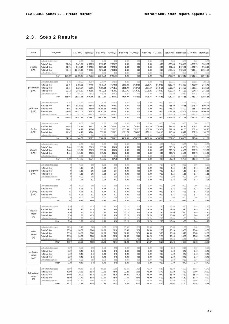
IEA ECBCS Annex 50 – Prefab Retrofit Retrofit Simulation Report, Appendix E
47
2.3. Step 2 Results
Month 1 (31 days) 2 (28 days) 3 (31 days) 4 (30 days) 5 (31 days) 6 (30 days) 7 (31 days) 8 (31 days) 9 (30 days) 10 (31 days) 11 (30 days) 12 (31 days)
Unheated attic space 0 0.00 0.00 0.00 0.00 0.00 0.00 0.00 0.00 0.00 0.00 0.00 0.00
Flats in 3 floor 51'070 9'649.75 8'392.30 7'138.42 3'876.59 0.00 0.00 0.00 0.00 1'653.88 3'948.63 6'960.76 9'449.52
Flats in 2 floor 31'374 6'110.17 5'270.27 4'235.13 1'970.36 0.00 0.00 0.00 0.00 872.66 2'372.81 4'436.74 6'106.26
Flats in 1 floor 55'415 10'439.33 9'088.64 7'676.14 4'088.06 0.00 0.00 0.00 0.00 1'879.45 4'306.68 7'615.11 10'321.38
Unheated basement 0 0.00 0.00 0.00 0.00 0.00 0.00 0.00 0.00 0.00 0.00 0.00 0.00
Sum 137'859 26'199.25 22'751.21 19'049.69 9'935.01 0.00 0.00 0.00 0.00 4'405.99 10'628.12 19'012.61 25'877.16
Unheated attic space 1'765 278.55 262.45 239.77 170.15 0.00 0.00 0.00 0.00 133.15 173.23 221.55 286.51
Flats in 3 floor ‐56'407 ‐8'758.81 ‐7'777.54 ‐7'048.59 ‐4'673.85 ‐1'561.30 ‐1'629.56 ‐1'821.76 ‐1'529.65 ‐2'510.73 ‐4'188.39 ‐6'432.99 ‐8'473.48
Flats in 2 floor ‐36'734 ‐5'228.57 ‐4'663.87 ‐4'156.18 ‐2'762.33 ‐1'555.94 ‐1'627.15 ‐1'817.69 ‐1'525.31 ‐1'728.37 ‐2'613.93 ‐3'915.21 ‐5'139.03
Flats in 1 floor ‐60'528 ‐9'545.85 ‐8'468.51 ‐7'572.53 ‐4'859.63 ‐1'521.75 ‐1'595.62 ‐1'779.21 ‐1'492.67 ‐2'723.13 ‐4'541.53 ‐7'084.52 ‐9'342.83
Unheated basement 3'426 585.06 537.70 448.72 228.25 0.00 0.00 0.00 0.00 215.29 320.12 474.26 616.24
Sum ‐153'668 ‐23'533.23 ‐20'909.92 ‐18'777.30 ‐12'295.81 ‐4'638.99 ‐4'852.33 ‐5'418.66 ‐4'547.63 ‐6'962.23 ‐11'343.85 ‐17'432.72 ‐22'955.34
Unheated attic space ‐1'765 ‐278.55 ‐262.45 ‐239.77 ‐170.15 0.00 0.00 0.00 0.00 ‐133.15 ‐173.23 ‐221.55 ‐286.51
Flats in 3 floor ‐8'682 ‐1'529.92 ‐1'364.85 ‐1'205.61 ‐744.07 0.00 0.00 0.00 0.00 ‐438.80 ‐746.18 ‐1'145.26 ‐1'507.44
Flats in 2 floor ‐8'652 ‐1'520.51 ‐1'356.56 ‐1'198.28 ‐748.83 0.00 0.00 0.00 0.00 ‐445.35 ‐745.00 ‐1'138.73 ‐1'498.55
Flats in 1 floor ‐8'684 ‐1'532.01 ‐1'366.70 ‐1'207.04 ‐742.61 0.00 0.00 0.00 0.00 ‐433.30 ‐746.05 ‐1'146.99 ‐1'509.74
Unheated basement ‐3'426 ‐585.06 ‐537.70 ‐448.72 ‐228.25 0.00 0.00 0.00 0.00 ‐215.29 ‐320.12 ‐474.26 ‐616.24
Sum ‐26'018 ‐4'582.44 ‐4'088.11 ‐3'610.93 ‐2'235.51 0.00 0.00 0.00 0.00 ‐1'317.45 ‐2'237.23 ‐3'430.98 ‐4'515.73
Unheated attic space 0 0.00 0.00 0.00 0.00 0.00 0.00 0.00 0.00 0.00 0.00 0.00 0.00
Flats in 3 floor 11'489 314.84 457.32 791.65 1'227.67 1'561.30 1'629.57 1'821.76 1'529.65 981.98 661.81 303.81 207.27
Flats in 2 floor 11'481 314.78 457.40 795.20 1'227.13 1'555.94 1'627.15 1'817.69 1'525.31 987.39 662.00 303.53 207.20
Flats in 1 floor 11'267 314.40 453.81 779.30 1'200.51 1'521.75 1'595.63 1'779.21 1'492.66 963.30 656.78 302.74 207.06
Unheated basement 0 0.00 0.00 0.00 0.00 0.00 0.00 0.00 0.00 0.00 0.00 0.00 0.00
Sum 34'236 944.02 1'368.53 2'366.15 3'655.31 4'638.99 4'852.35 5'418.66 4'547.62 2'932.67 1'980.59 910.08 621.53
Unheated attic space 0 0.00 0.00 0.00 0.00 0.00 0.00 0.00 0.00 0.00 0.00 0.00 0.00
Flats in 3 floor 2'466 315.95 285.38 315.95 305.76 0.00 0.00 0.00 0.00 305.76 315.95 305.76 315.95
Flats in 2 floor 2'466 315.95 285.38 315.95 305.76 0.00 0.00 0.00 0.00 305.76 315.95 305.76 315.95
Flats in 1 floor 2'466 315.95 285.38 315.95 305.76 0.00 0.00 0.00 0.00 305.76 315.95 305.76 315.95
Unheated basement 0 0.00 0.00 0.00 0.00 0.00 0.00 0.00 0.00 0.00 0.00 0.00 0.00
Sum 7'399 947.85 856.14 947.85 917.28 0.00 0.00 0.00 0.00 917.28 947.85 917.28 947.85
Unheated attic space 0 0.00 0.00 0.00 0.00 0.00 0.00 0.00 0.00 0.00 0.00 0.00 0.00
Flats in 3 floor 9 1.18 1.07 1.18 1.14 0.00 0.00 0.00 0.00 1.14 1.18 1.14 1.18
Flats in 2 floor 9 1.18 1.07 1.18 1.14 0.00 0.00 0.00 0.00 1.14 1.18 1.14 1.18
Flats in 1 floor 9 1.18 1.07 1.18 1.14 0.00 0.00 0.00 0.00 1.14 1.18 1.14 1.18
Unheated basement 0 0.00 0.00 0.00 0.00 0.00 0.00 0.00 0.00 0.00 0.00 0.00 0.00
Sum 28 3.54 3.21 3.54 3.42 0.00 0.00 0.00 0.00 3.42 3.54 3.42 3.54
Unheated attic space 0 0.00 0.00 0.00 0.00 0.00 0.00 0.00 0.00 0.00 0.00 0.00 0.00
Flats in 3 floor 55 6.99 6.32 6.99 6.77 0.00 0.00 0.00 0.00 6.77 6.99 6.77 6.99
Flats in 2 floor 55 6.99 6.32 6.99 6.77 0.00 0.00 0.00 0.00 6.77 6.99 6.77 6.99
Flats in 1 floor 55 6.99 6.32 6.99 6.77 0.00 0.00 0.00 0.00 6.77 6.99 6.77 6.99
Unheated basement 0 0.00 0.00 0.00 0.00 0.00 0.00 0.00 0.00 0.00 0.00 0.00 0.00
Sum 164 20.97 18.96 20.97 20.31 0.00 0.00 0.00 0.00 20.31 20.97 20.31 20.97
Unheated attic space 8.30 ‐1.50 ‐1.20 2.90 8.90 13.10 16.30 18.70 17.80 13.40 9.30 3.40 ‐1.10
Flats in 3 floor 8.30 ‐1.50 ‐1.20 2.90 8.90 13.10 16.30 18.70 17.80 13.40 9.30 3.40 ‐1.10
Flats in 2 floor 8.30 ‐1.50 ‐1.20 2.90 8.90 13.10 16.30 18.70 17.80 13.40 9.30 3.40 ‐1.10
Flats in 1 floor 8.30 ‐1.50 ‐1.20 2.90 8.90 13.10 16.30 18.70 17.80 13.40 9.30 3.40 ‐1.10
Unheated basement 8.30 ‐1.50 ‐1.20 2.90 8.90 13.10 16.30 18.70 17.80 13.40 9.30 3.40 ‐1.10
Mean 8.30 ‐1.50 ‐1.20 2.90 8.90 13.10 16.30 18.70 17.80 13.40 9.30 3.40 ‐1.10
Unheated attic space 11.20 2.40 2.80 6.20 11.30 15.40 18.10 21.30 19.90 15.40 11.80 6.60 2.90
Flats in 3 floor 20.50 20.00 20.00 20.00 20.10 17.90 20.30 24.00 22.90 20.20 20.00 20.00 20.00
Flats in 2 floor 20.70 20.00 20.00 20.00 20.20 18.80 20.90 24.90 23.80 20.30 20.10 20.00 20.00
Flats in 1 floor 20.50 20.00 20.00 20.00 20.10 18.00 20.20 24.20 22.90 20.10 20.00 20.00 20.00
Unheated basement 12.60 5.90 6.20 8.50 11.80 14.90 17.60 20.70 19.90 16.20 13.30 9.50 6.60
Mean 20.57 20.00 20.00 20.00 20.13 18.23 20.47 24.37 23.20 20.20 20.03 20.00 20.00
Unheated attic space 0.30 0.50 0.50 0.50 0.50 0.00 0.00 0.00 0.00 0.50 0.50 0.50 0.50
Flats in 3 floor 0.30 0.40 0.40 0.40 0.40 0.00 0.00 0.00 0.00 0.40 0.40 0.40 0.40
Flats in 2 floor 0.30 0.40 0.40 0.40 0.40 0.00 0.00 0.00 0.00 0.40 0.40 0.40 0.40
Flats in 1 floor 0.30 0.40 0.40 0.40 0.40 0.00 0.00 0.00 0.00 0.40 0.40 0.40 0.40
Unheated basement 0.30 0.50 0.50 0.50 0.50 0.00 0.00 0.00 0.00 0.50 0.50 0.50 0.50
Mean 0.30 0.40 0.40 0.40 0.40 0.00 0.00 0.00 0.00 0.40 0.40 0.40 0.40
Unheated attic space 58.00 59.30 60.70 56.20 55.90 63.40 53.10 43.50 47.80 65.80 62.00 66.60 62.40
Flats in 3 floor 45.50 28.80 30.40 32.90 42.40 72.20 61.90 49.30 53.40 59.10 47.60 37.90 30.30
Flats in 2 floor 44.60 29.00 30.70 33.10 42.20 68.20 59.70 46.80 50.40 58.70 47.60 38.10 30.50
Flats in 1 floor 45.40 28.70 30.40 32.90 42.40 71.30 62.40 48.90 53.10 59.30 47.60 37.80 30.20
Unheated basement 53.40 47.30 49.60 48.30 54.20 67.10 56.30 46.50 49.00 62.60 56.50 55.00 48.70
Mean 45.17 28.83 30.50 32.97 42.33 70.57 61.33 48.33 52.30 59.03 47.60 37.93 30.33
Rel. Moisture
(mean)
[%]
qTransmission
[kWh]
tIndoor
(mean)
[°C]
AirChange
(mean)
[hod‐1]
Sum/Mean
qEquipment
[kWh]
qLighting
[kWh]
tOutdoor
(mean)
[°C]
qHeating
[kWh]
qInfiltration
[kWh]
qSunRad
[kWh]
qPeople
[kWh]
IEA ECBCS Annex 50 – Prefab Retrofit Retrofit Simulation Report, Appendix E
48
3. University of Minho Results
3.1. Introduction
The Cases 1 and 2 were simulated applying the Portuguese Thermal Regulation (RCCTE) methodology, which is a steady-state calculation method based on the degree-days. Following this methodology we have calculated the useful and delivered energy needs.
As required, all the necessary inputs were the ones given to us in the Specifications Document and the climatic data necessary in case 1 was calculated using the files: Lucerne_monthly.xls; lucerne_ hour-ly.xls:
Degree-Days= 3362 K·d;
Esouth (incident south solar energy) = 1.930 kW/(m2·d);
Heating Period = 7.6 months;
Thermal Amplitude = 9.03 K
Case 2 corresponds to Guimarães, a Potuguese city located in the north of Portugal, 50 km away from the sea:
Degree-Days= 1770 K·d;
Esouth (incident south solar energy) = 3.1 kW/m2·d);
Heating Period = 7 months;
Thermal Amplitude = 14 K
3.2. Calculation procedures
Following the RCCTE calculation procedures, the energy needs of each apartment were calculated. The identification of each apartment is the following:
Legend:
B1P1_D -> B1 – Building 1; P1 – Floor 1; D – right apartment
B1P1_E -> B1 – Building 1; P1 – Floor 1; E – left apartment
B1P2_D -> B1 – Building 1; P2 – Floor 2; D – right apartment
B1P2_E -> B1 – Building 1; P2 – Floor 2; E – left apartment
B1P3_D -> B1 – Building 1; P3 – Floor 3; D – right apartment
B1P3_E -> B1 – Building 1; P3 – Floor 3; E – left apartment
B1S_E -> B1 – Building 1; S – attic; E – left apartment
B1S_F -> B1 – Building 1; S – attic; F – front apartment
B2P1_D -> B2 – Building 1; P1 – Floor 1; D – right apartment
B2P1_E -> B2 – Building 1; P1 – Floor 1; E – left apartment
B2P2_D -> B2 – Building 1; P2 – Floor 2; D – right apartment
B2P2_E -> B2 – Building 1; P2 – Floor 2; E – left apartment
B2P3_D -> B2 – Building 1; P3 – Floor 3; D – right apartment
B2P3_E -> B2 – Building 1; P3 – Floor 3; E – left apartment
B2S_E -> B2 – Building 1; S – attic; E – left apartment
B2S_F -> B2 – Building 1; S – attic; F – front apartment
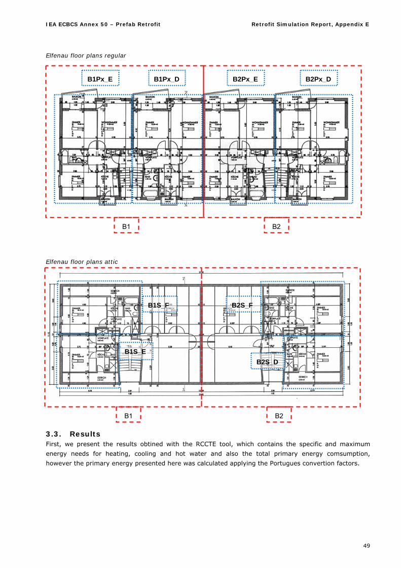
IEA ECBCS Annex 50 – Prefab Retrofit Retrofit Simulation Report, Appendix E
49
Elfenau floor plans regular
Elfenau floor plans attic
3.3. Results First, we present the results obtined with the RCCTE tool, which contains the specific and maximum
energy needs for heating, cooling and hot water and also the total primary energy comsumption,
however the primary energy presented here was calculated applying the Portugues convertion factors.
B1 B2
B1 B2
B2S_D
B2S_F
B1S_E
B1S_F
B1Px_E B1Px_D B2Px_E B2Px_D
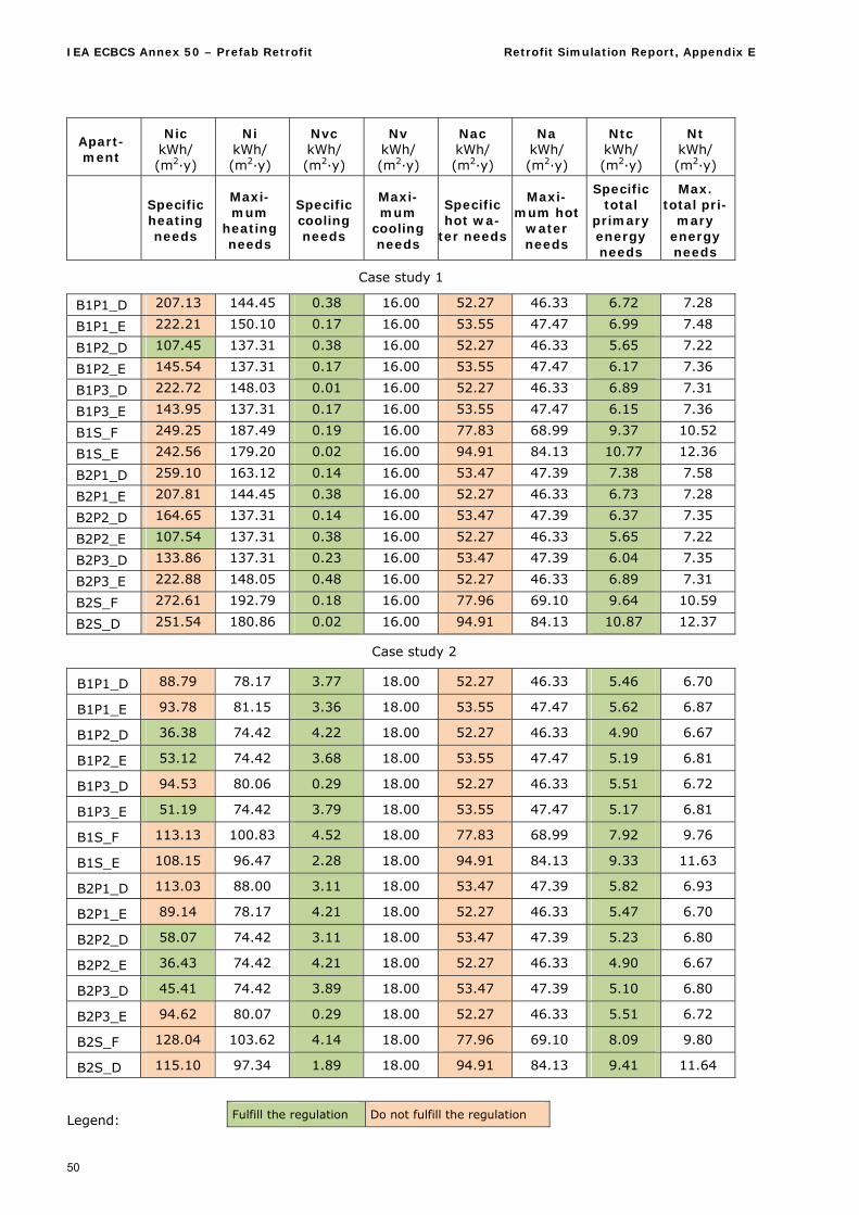
IEA ECBCS Annex 50 – Prefab Retrofit Retrofit Simulation Report, Appendix E
50
Apart-ment
Nic kWh/ (m2·y)
Ni kWh/ (m2·y)
Nvc kWh/ (m2·y)
Nv kWh/ (m2·y)
Nac kWh/ (m2·y)
Na kWh/ (m2·y)
Ntc kWh/ (m2·y)
Nt kWh/ (m2·y)
Specific heating needs
Maxi-mum
heating needs
Specific cooling needs
Maxi-mum
cooling needs
Specific hot wa-
ter needs
Maxi-mum hot
water needs
Specific total
primary energy needs
Max. total pri-
mary energy needs
Case study 1
B1P1_D 207.13 144.45 0.38 16.00 52.27 46.33 6.72 7.28
B1P1_E 222.21 150.10 0.17 16.00 53.55 47.47 6.99 7.48
B1P2_D 107.45 137.31 0.38 16.00 52.27 46.33 5.65 7.22
B1P2_E 145.54 137.31 0.17 16.00 53.55 47.47 6.17 7.36
B1P3_D 222.72 148.03 0.01 16.00 52.27 46.33 6.89 7.31
B1P3_E 143.95 137.31 0.17 16.00 53.55 47.47 6.15 7.36
B1S_F 249.25 187.49 0.19 16.00 77.83 68.99 9.37 10.52
B1S_E 242.56 179.20 0.02 16.00 94.91 84.13 10.77 12.36
B2P1_D 259.10 163.12 0.14 16.00 53.47 47.39 7.38 7.58
B2P1_E 207.81 144.45 0.38 16.00 52.27 46.33 6.73 7.28
B2P2_D 164.65 137.31 0.14 16.00 53.47 47.39 6.37 7.35
B2P2_E 107.54 137.31 0.38 16.00 52.27 46.33 5.65 7.22
B2P3_D 133.86 137.31 0.23 16.00 53.47 47.39 6.04 7.35
B2P3_E 222.88 148.05 0.48 16.00 52.27 46.33 6.89 7.31
B2S_F 272.61 192.79 0.18 16.00 77.96 69.10 9.64 10.59
B2S_D 251.54 180.86 0.02 16.00 94.91 84.13 10.87 12.37
Case study 2
B1P1_D 88.79 78.17 3.77 18.00 52.27 46.33 5.46 6.70
B1P1_E 93.78 81.15 3.36 18.00 53.55 47.47 5.62 6.87
B1P2_D 36.38 74.42 4.22 18.00 52.27 46.33 4.90 6.67
B1P2_E 53.12 74.42 3.68 18.00 53.55 47.47 5.19 6.81
B1P3_D 94.53 80.06 0.29 18.00 52.27 46.33 5.51 6.72
B1P3_E 51.19 74.42 3.79 18.00 53.55 47.47 5.17 6.81
B1S_F 113.13 100.83 4.52 18.00 77.83 68.99 7.92 9.76
B1S_E 108.15 96.47 2.28 18.00 94.91 84.13 9.33 11.63
B2P1_D 113.03 88.00 3.11 18.00 53.47 47.39 5.82 6.93
B2P1_E 89.14 78.17 4.21 18.00 52.27 46.33 5.47 6.70
B2P2_D 58.07 74.42 3.11 18.00 53.47 47.39 5.23 6.80
B2P2_E 36.43 74.42 4.21 18.00 52.27 46.33 4.90 6.67
B2P3_D 45.41 74.42 3.89 18.00 53.47 47.39 5.10 6.80
B2P3_E 94.62 80.07 0.29 18.00 52.27 46.33 5.51 6.72
B2S_F 128.04 103.62 4.14 18.00 77.96 69.10 8.09 9.80
B2S_D 115.10 97.34 1.89 18.00 94.91 84.13 9.41 11.64
Legend: Fulfill the regulation Do not fulfill the regulation
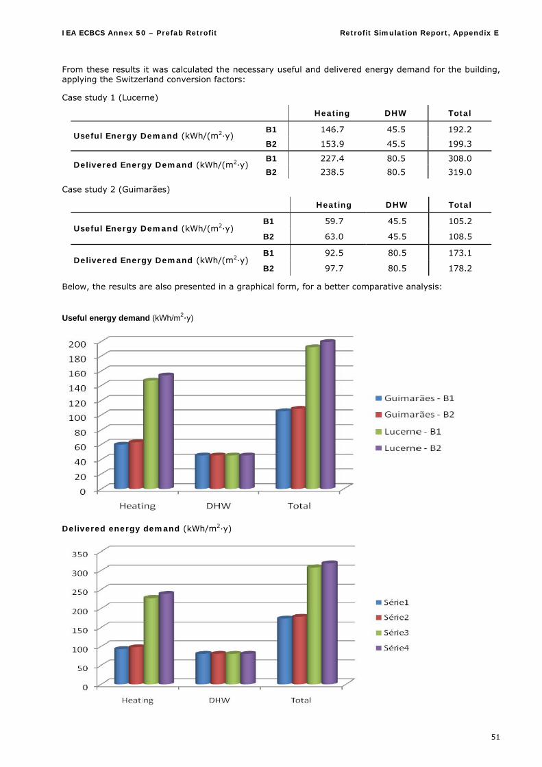
IEA ECBCS Annex 50 – Prefab Retrofit Retrofit Simulation Report, Appendix E
51
From these results it was calculated the necessary useful and delivered energy demand for the building, applying the Switzerland conversion factors:
Case study 1 (Lucerne)
Heating DHW Total
B1 146.7 45.5 192.2 Useful Energy Demand (kWh/(m2·y)
B2 153.9 45.5 199.3
B1 227.4 80.5 308.0 Delivered Energy Demand (kWh/(m2·y)
B2 238.5 80.5 319.0
Case study 2 (Guimarães)
Heating DHW Total
B1 59.7 45.5 105.2 Useful Energy Demand (kWh/(m2·y)
B2 63.0 45.5 108.5
B1 92.5 80.5 173.1 Delivered Energy Demand (kWh/(m2·y)
B2 97.7 80.5 178.2
Below, the results are also presented in a graphical form, for a better comparative analysis:
Useful energy demand (kWh/m2·y)
Delivered energy demand (kWh/m2·y)
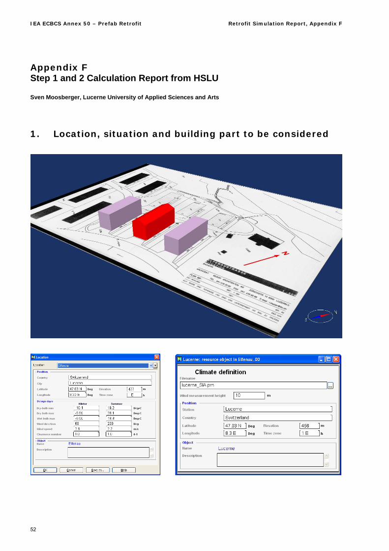
IEA ECBCS Annex 50 – Prefab Retrofit Retrofit Simulation Report, Appendix F
52
Appendix F Step 1 and 2 Calculation Report from HSLU Sven Moosberger, Lucerne University of Applied Sciences and Arts
1. Location, situation and building part to be considered
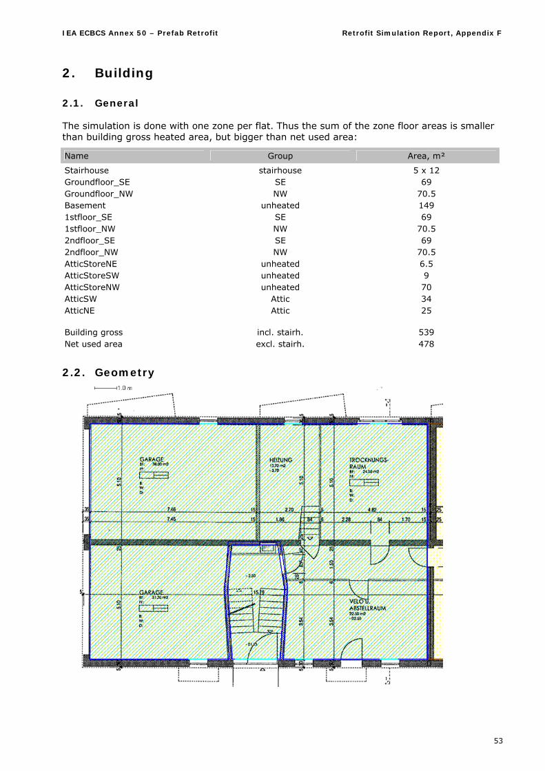
IEA ECBCS Annex 50 – Prefab Retrofit Retrofit Simulation Report, Appendix F
53
2. Building
2.1. General The simulation is done with one zone per flat. Thus the sum of the zone floor areas is smaller than building gross heated area, but bigger than net used area:
Name Group Area, m²
Stairhouse stairhouse 5 x 12 Groundfloor_SE SE 69 Groundfloor_NW NW 70.5 Basement unheated 149 1stfloor_SE SE 69 1stfloor_NW NW 70.5 2ndfloor_SE SE 69 2ndfloor_NW NW 70.5 AtticStoreNE unheated 6.5 AtticStoreSW unheated 9 AtticStoreNW unheated 70 AtticSW Attic 34 AtticNE Attic 25 Building gross incl. stairh. 539 Net used area excl. stairh. 478
2.2. Geometry
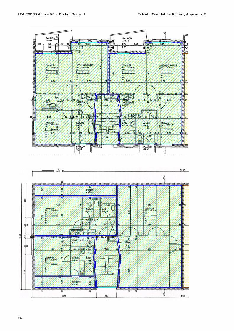
IEA ECBCS Annex 50 – Prefab Retrofit Retrofit Simulation Report, Appendix F
54
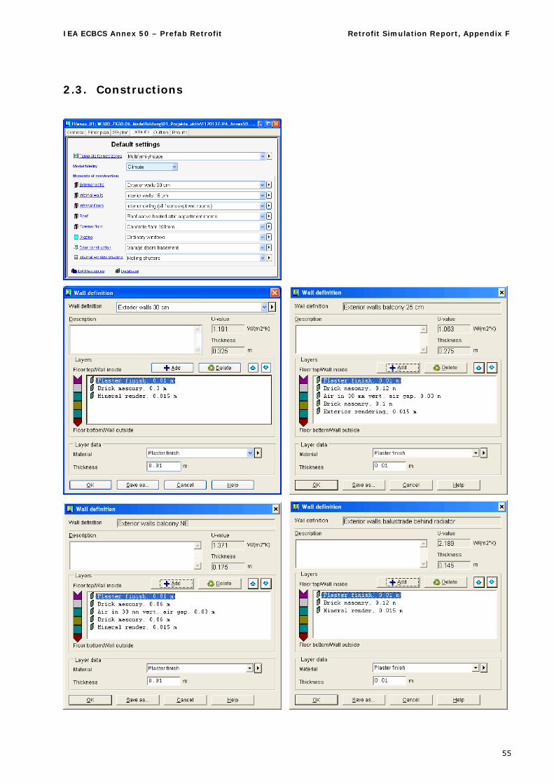
IEA ECBCS Annex 50 – Prefab Retrofit Retrofit Simulation Report, Appendix F
55
2.3. Constructions
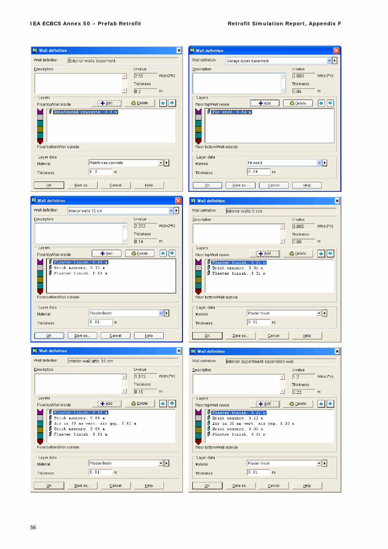
IEA ECBCS Annex 50 – Prefab Retrofit Retrofit Simulation Report, Appendix F
56
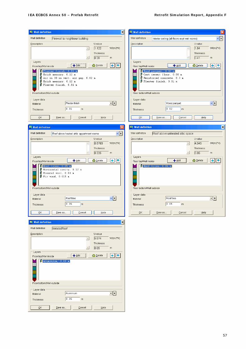
IEA ECBCS Annex 50 – Prefab Retrofit Retrofit Simulation Report, Appendix F
57
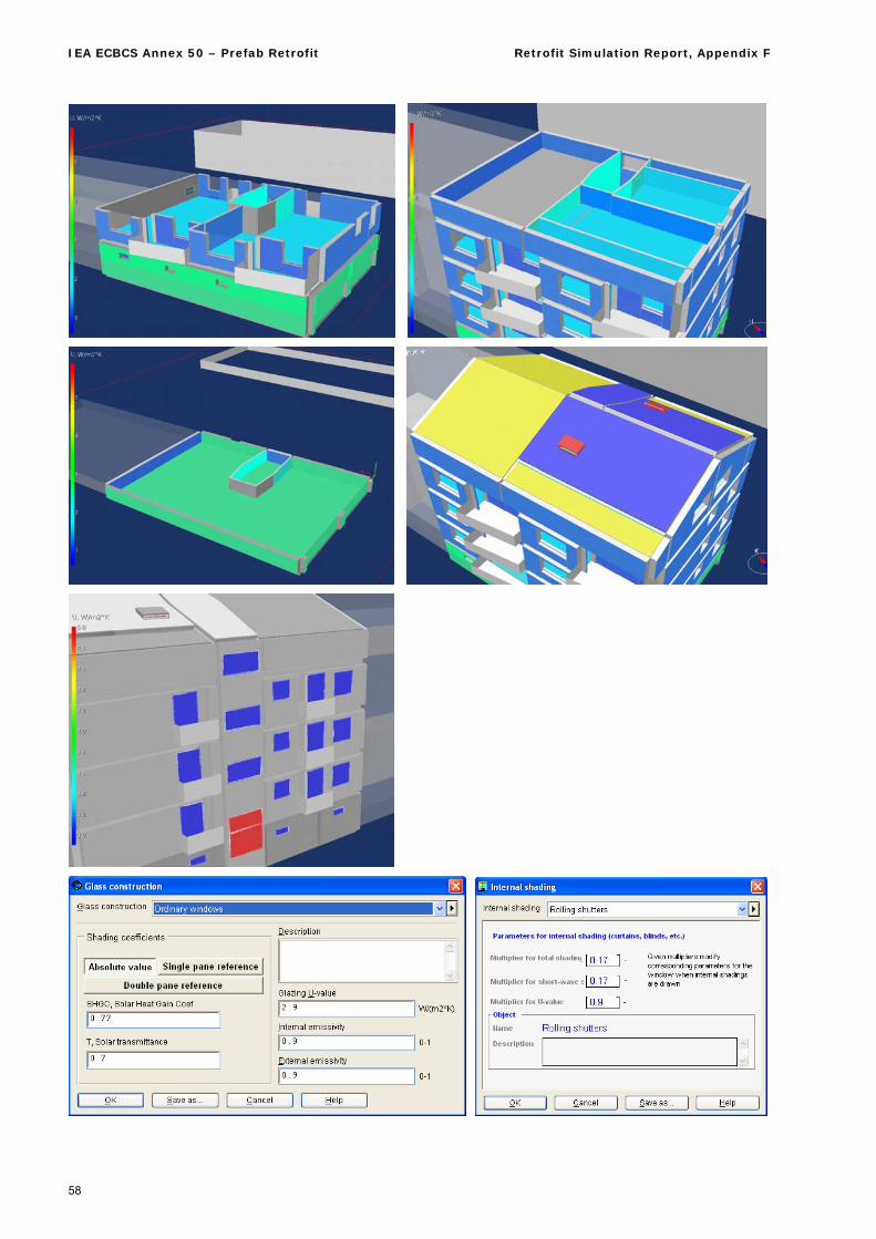
IEA ECBCS Annex 50 – Prefab Retrofit Retrofit Simulation Report, Appendix F
58
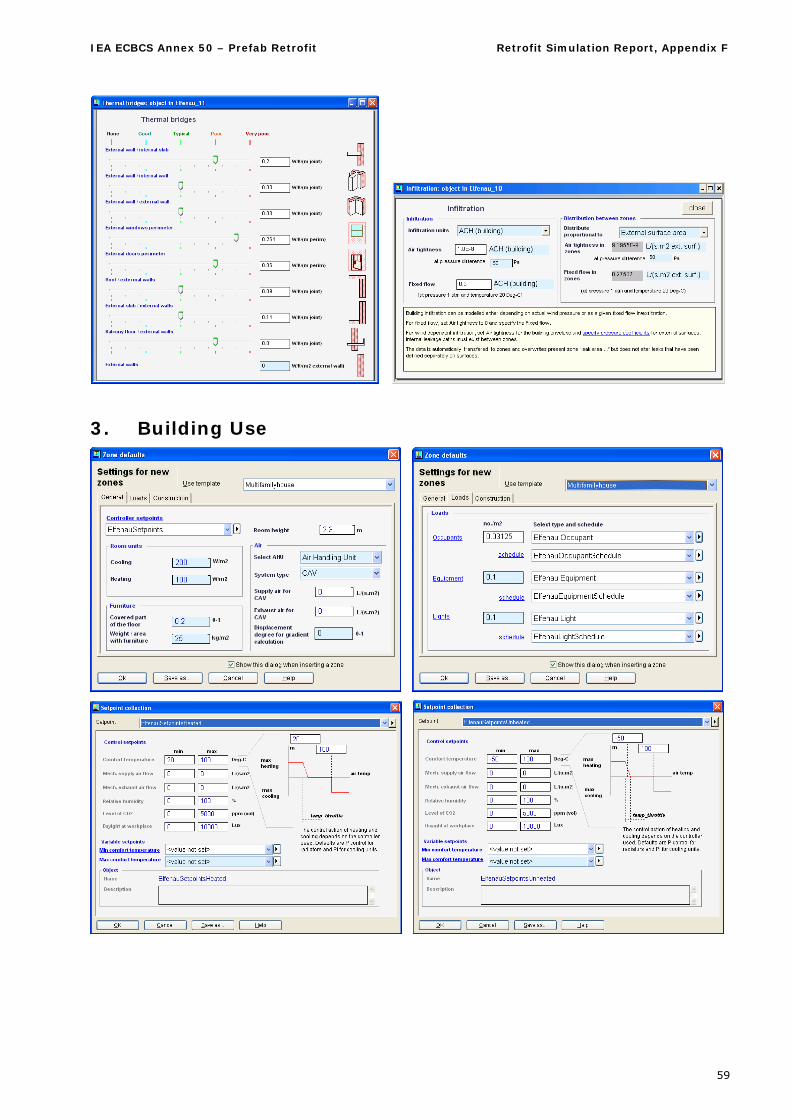
IEA ECBCS Annex 50 – Prefab Retrofit Retrofit Simulation Report, Appendix F
59
3. Building Use
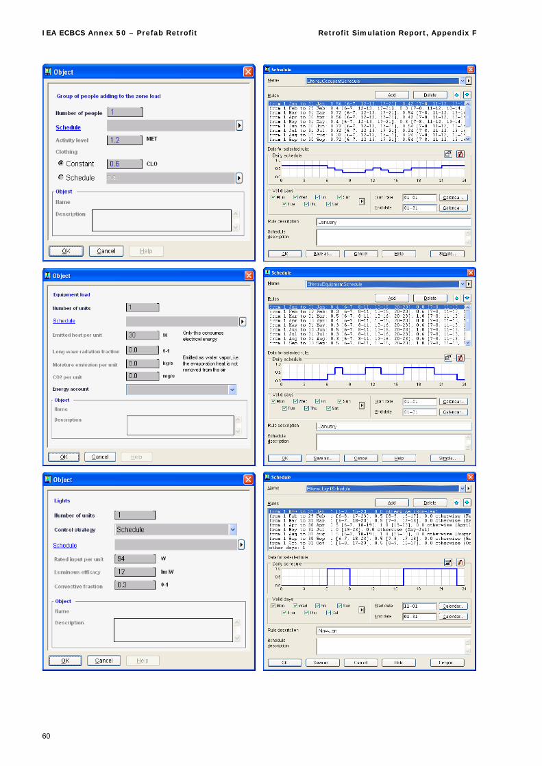
IEA ECBCS Annex 50 – Prefab Retrofit Retrofit Simulation Report, Appendix F
60
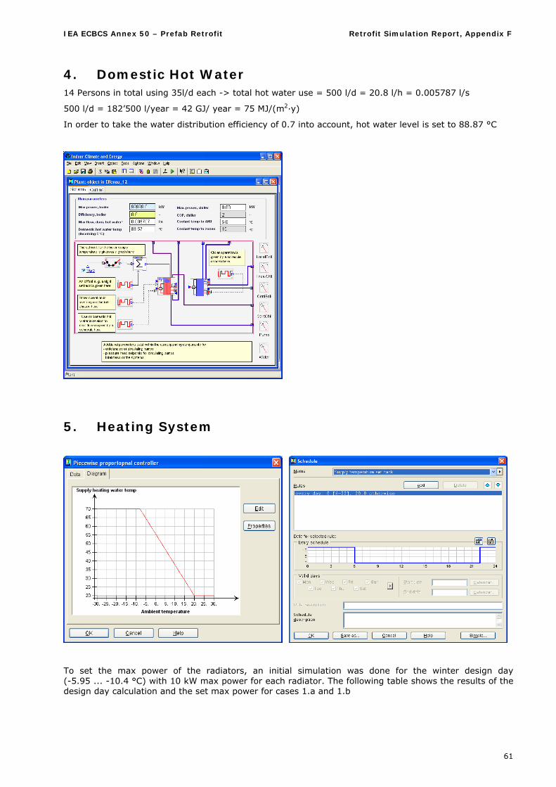
IEA ECBCS Annex 50 – Prefab Retrofit Retrofit Simulation Report, Appendix F
61
4. Domestic Hot Water 14 Persons in total using 35l/d each -> total hot water use = 500 l/d = 20.8 l/h = 0.005787 l/s
500 l/d = 182’500 l/year = 42 GJ/ year = 75 MJ/(m2·y)
In order to take the water distribution efficiency of 0.7 into account, hot water level is set to 88.87 °C
5. Heating System
To set the max power of the radiators, an initial simulation was done for the winter design day (-5.95 ... -10.4 °C) with 10 kW max power for each radiator. The following table shows the results of the design day calculation and the set max power for cases 1.a and 1.b
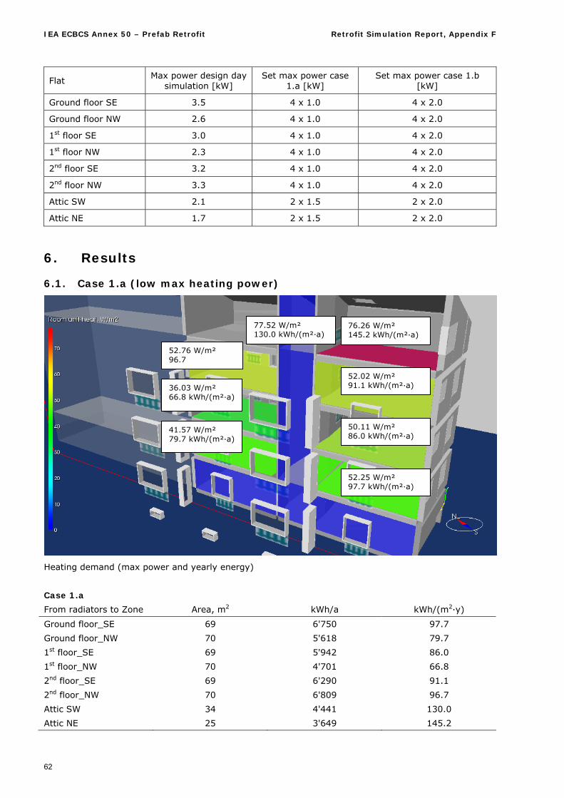
IEA ECBCS Annex 50 – Prefab Retrofit Retrofit Simulation Report, Appendix F
62
Flat Max power design day
simulation [kW] Set max power case
1.a [kW] Set max power case 1.b
[kW]
Ground floor SE 3.5 4 x 1.0 4 x 2.0
Ground floor NW 2.6 4 x 1.0 4 x 2.0
1st floor SE 3.0 4 x 1.0 4 x 2.0
1st floor NW 2.3 4 x 1.0 4 x 2.0
2nd floor SE 3.2 4 x 1.0 4 x 2.0
2nd floor NW 3.3 4 x 1.0 4 x 2.0
Attic SW 2.1 2 x 1.5 2 x 2.0
Attic NE 1.7 2 x 1.5 2 x 2.0
6. Results
6.1. Case 1.a (low max heating power)
Heating demand (max power and yearly energy)
Case 1.a
From radiators to Zone Area, m2 kWh/a kWh/(m2·y)
Ground floor_SE 69 6'750 97.7
Ground floor_NW 70 5'618 79.7
1st floor_SE 69 5'942 86.0
1st floor_NW 70 4'701 66.8
2nd floor_SE 69 6'290 91.1
2nd floor_NW 70 6'809 96.7
Attic SW 34 4'441 130.0
Attic NE 25 3'649 145.2
52.25 W/m² 97.7 kWh/(m²·a)
41.57 W/m² 79.7 kWh/(m²·a)
50.11 W/m² 86.0 kWh/(m²·a)
36.03 W/m² 66.8 kWh/(m²·a)
52.02 W/m² 91.1 kWh/(m²·a)
52.76 W/m² 96.7
77.52 W/m² 130.0 kWh/(m²·a)
76.26 W/m²
145.2 kWh/(m²·a)
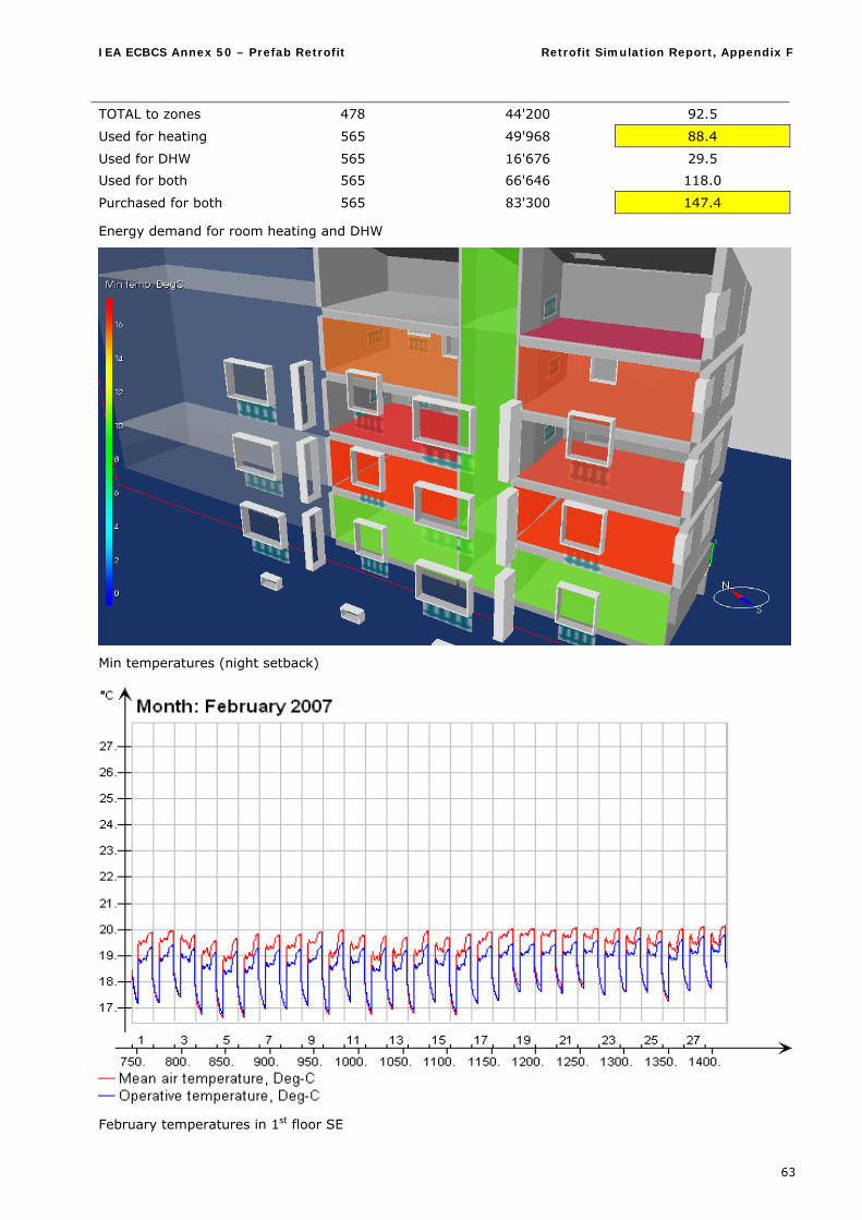
IEA ECBCS Annex 50 – Prefab Retrofit Retrofit Simulation Report, Appendix F
63
TOTAL to zones 478 44'200 92.5
Used for heating 565 49'968 88.4
Used for DHW 565 16'676 29.5
Used for both 565 66'646 118.0
Purchased for both 565 83'300 147.4
Energy demand for room heating and DHW
Min temperatures (night setback)
February temperatures in 1st floor SE
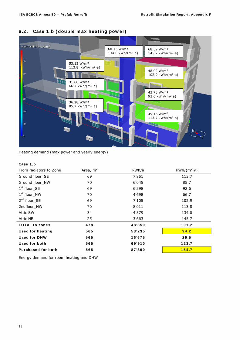
IEA ECBCS Annex 50 – Prefab Retrofit Retrofit Simulation Report, Appendix F
64
6.2. Case 1.b (double max heating power)
Heating demand (max power and yearly energy)
Case 1.b
From radiators to Zone Area, m2 kWh/a kWh/(m2·y)
Ground floor_SE 69 7'851 113.7
Ground floor_NW 70 6'045 85.7
1st floor_SE 69 6'398 92.6
1st floor_NW 70 4'698 66.7
2nd floor_SE 69 7'105 102.9
2ndfloor_NW 70 8'011 113.8
Attic SW 34 4'579 134.0
Attic NE 25 3'663 145.7
TOTAL to zones 478 48'350 101.2
Used for heating 565 53'235 94.2
Used for DHW 565 16'675 29.5
Used for both 565 69'910 123.7
Purchased for both 565 87'390 154.7
Energy demand for room heating and DHW
49.16 W/m2 113.7 kWh/(m²·a)
36.28 W/m² 85.7 kWh/(m²·a)
42.78 W/m² 92.6 kWh/(m²·a)
31.68 W/m² 66.7 kWh/(m²·a)
48.02 W/m² 102.9 kWh/(m²·a)
53.13 W/m² 113.8 kWh/(m²·a)
68.13 W/m² 134.0 kWh/(m²·a)
68.59 W/m² 145.7 kWh/(m²·a)
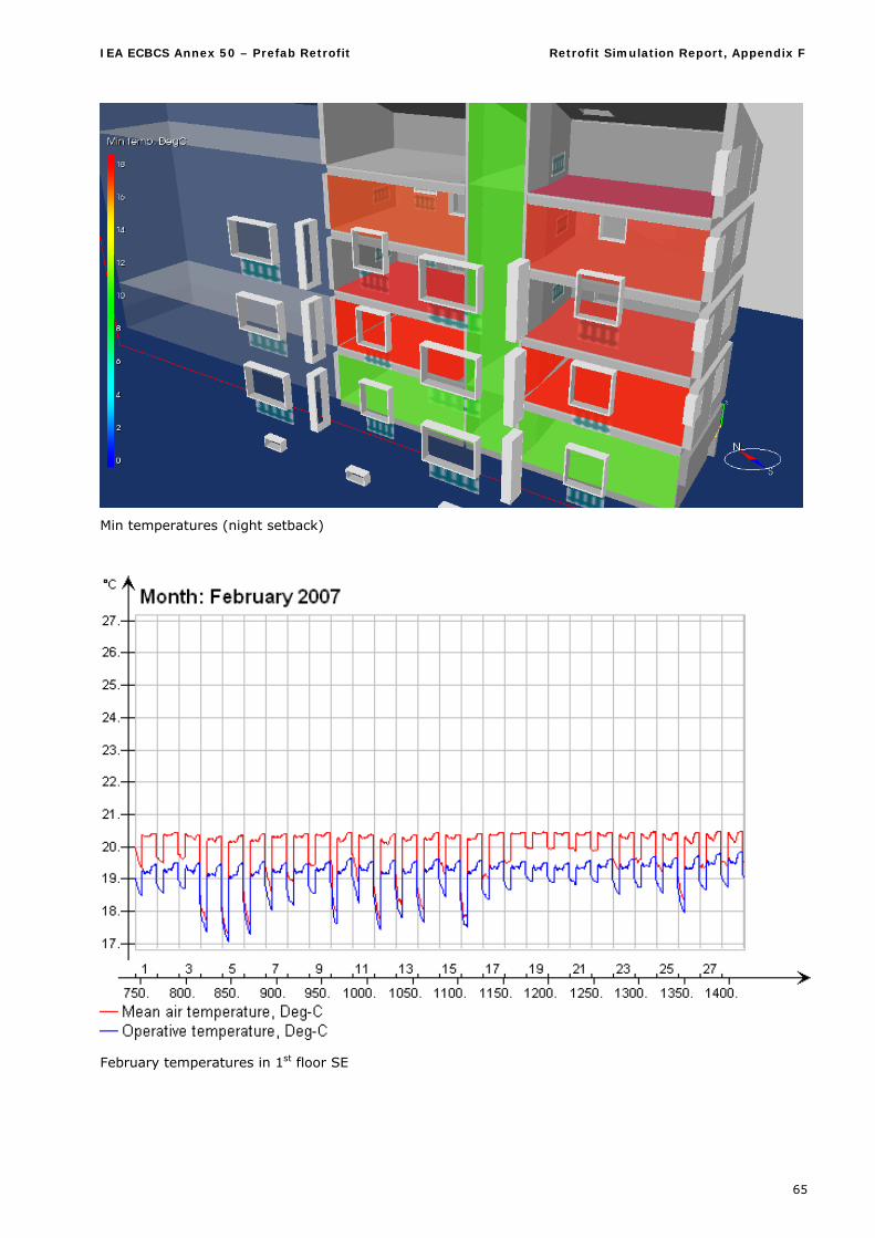
IEA ECBCS Annex 50 – Prefab Retrofit Retrofit Simulation Report, Appendix F
65
Min temperatures (night setback)
February temperatures in 1st floor SE
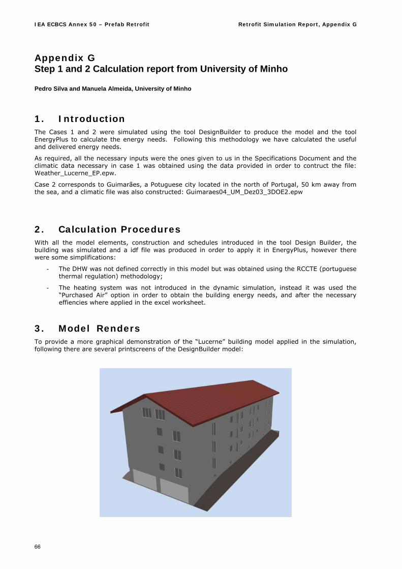
IEA ECBCS Annex 50 – Prefab Retrofit Retrofit Simulation Report, Appendix G
66
Appendix G Step 1 and 2 Calculation report from University of Minho
Pedro Silva and Manuela Almeida, University of Minho
1. Introduction The Cases 1 and 2 were simulated using the tool DesignBuilder to produce the model and the tool EnergyPlus to calculate the energy needs. Following this methodology we have calculated the useful and delivered energy needs.
As required, all the necessary inputs were the ones given to us in the Specifications Document and the climatic data necessary in case 1 was obtained using the data provided in order to contruct the file: Weather_Lucerne_EP.epw.
Case 2 corresponds to Guimarães, a Potuguese city located in the north of Portugal, 50 km away from the sea, and a climatic file was also constructed: Guimaraes04_UM_Dez03_3DOE2.epw
2. Calculation Procedures With all the model elements, construction and schedules introduced in the tool Design Builder, the building was simulated and a idf file was produced in order to apply it in EnergyPlus, however there were some simplifications:
- The DHW was not defined correctly in this model but was obtained using the RCCTE (portuguese thermal regulation) methodology;
- The heating system was not introduced in the dynamic simulation, instead it was used the “Purchased Air” option in order to obtain the building energy needs, and after the necessary effiencies where applied in the excel worksheet.
3. Model Renders To provide a more graphical demonstration of the “Lucerne” building model applied in the simulation, following there are several printscreens of the DesignBuilder model:
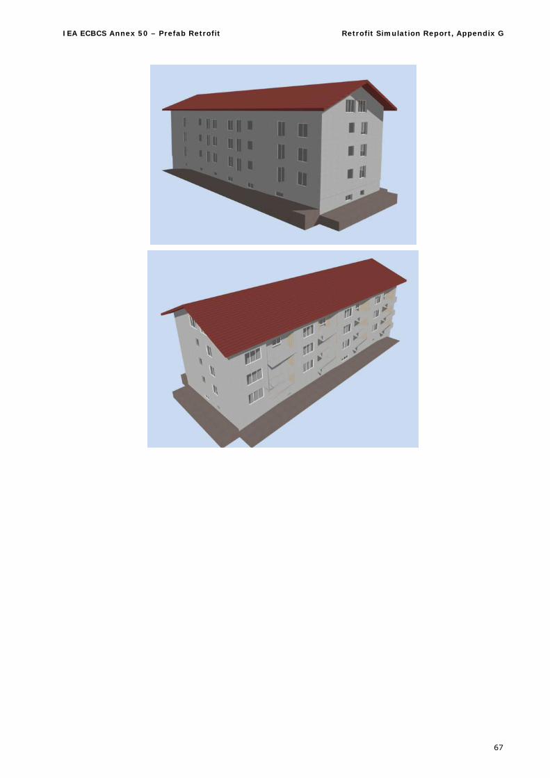
IEA ECBCS Annex 50 – Prefab Retrofit Retrofit Simulation Report, Appendix G
67
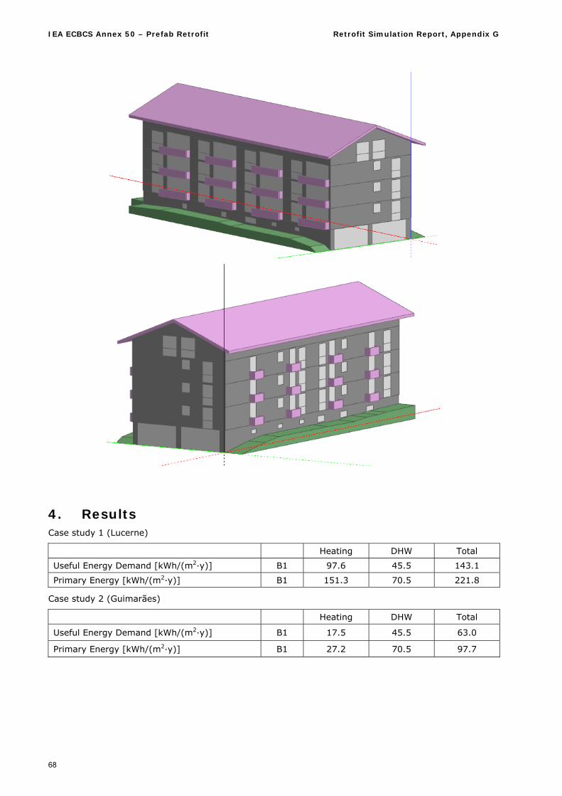
IEA ECBCS Annex 50 – Prefab Retrofit Retrofit Simulation Report, Appendix G
68
4. Results Case study 1 (Lucerne)
Heating DHW Total
Useful Energy Demand [kWh/(m2·y)] B1 97.6 45.5 143.1
Primary Energy [kWh/(m2·y)] B1 151.3 70.5 221.8
Case study 2 (Guimarães)
Heating DHW Total
Useful Energy Demand [kWh/(m2·y)] B1 17.5 45.5 63.0
Primary Energy [kWh/(m2·y)] B1 27.2 70.5 97.7
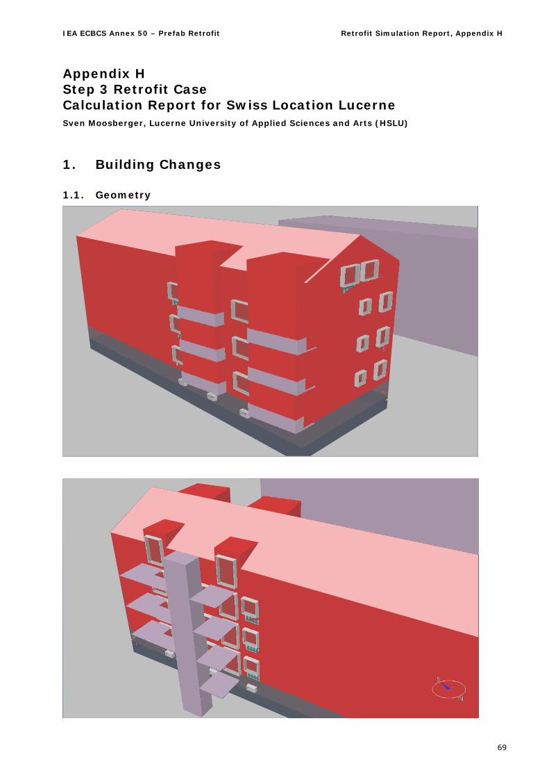
IEA ECBCS Annex 50 – Prefab Retrofit Retrofit Simulation Report, Appendix H
69
Appendix H Step 3 Retrofit Case Calculation Report for Swiss Location Lucerne Sven Moosberger, Lucerne University of Applied Sciences and Arts (HSLU)
1. Building Changes
1.1. Geometry
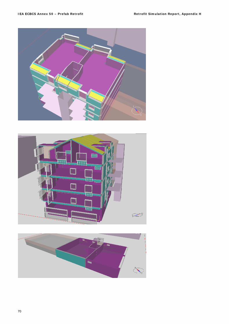
IEA ECBCS Annex 50 – Prefab Retrofit Retrofit Simulation Report, Appendix H
70
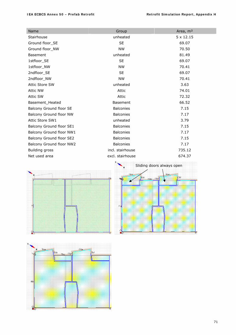
IEA ECBCS Annex 50 – Prefab Retrofit Retrofit Simulation Report, Appendix H
71
Name Group Area, m²
Stairhouse unheated 5 x 12.15
Ground floor_SE SE 69.07
Ground floor_NW NW 70.50
Basement unheated 81.49
1stfloor_SE SE 69.07
1stfloor_NW NW 70.41
2ndfloor_SE SE 69.07
2ndfloor_NW NW 70.41
Attic Store SW unheated 3.63
Attic NW Attic 74.01
Attic SW Attic 72.32
Basement_Heated Basement 66.52
Balcony Ground floor SE Balconies 7.15
Balcony Ground floor NW Balconies 7.17
Attic Store SW1 unheated 3.79
Balcony Ground floor SE1 Balconies 7.15
Balcony Ground floor NW1 Balconies 7.17
Balcony Ground floor SE2 Balconies 7.15
Balcony Ground floor NW2 Balconies 7.17
Building gross incl. stairhouse 735.12
Net used area excl. stairhouse 674.37
Sliding doors always open
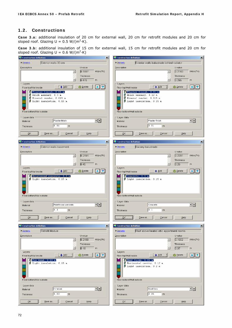
IEA ECBCS Annex 50 – Prefab Retrofit Retrofit Simulation Report, Appendix H
72
1.2. Constructions
Case 3.a: additional insulation of 20 cm for external wall, 20 cm for retrofit modules and 20 cm for sloped roof. Glazing U = 0.5 W/(m2·K).
Case 3.b: additional insulation of 15 cm for external wall, 15 cm for retrofit modules and 20 cm for sloped roof. Glazing U = 0.6 W/(m2·K)
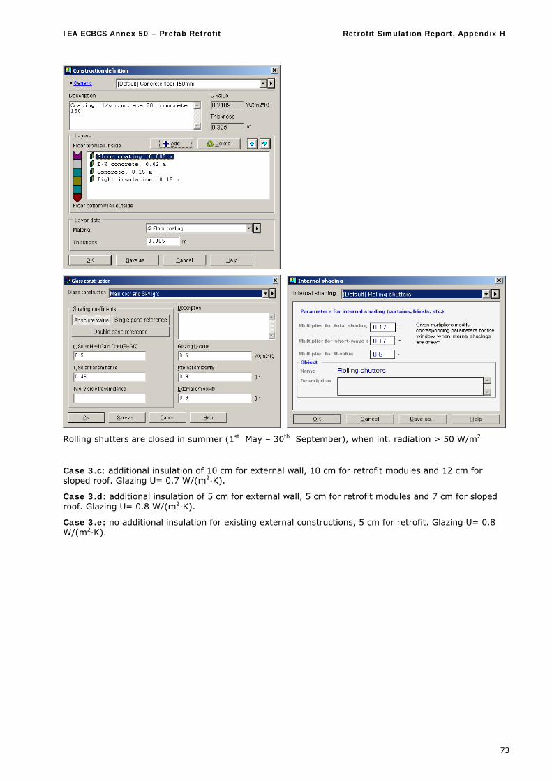
IEA ECBCS Annex 50 – Prefab Retrofit Retrofit Simulation Report, Appendix H
73
Rolling shutters are closed in summer (1st May – 30th September), when int. radiation > 50 W/m2
Case 3.c: additional insulation of 10 cm for external wall, 10 cm for retrofit modules and 12 cm for sloped roof. Glazing U= 0.7 W/(m2·K).
Case 3.d: additional insulation of 5 cm for external wall, 5 cm for retrofit modules and 7 cm for sloped roof. Glazing U= 0.8 W/(m2·K).
Case 3.e: no additional insulation for existing external constructions, 5 cm for retrofit. Glazing U= 0.8 W/(m2·K).
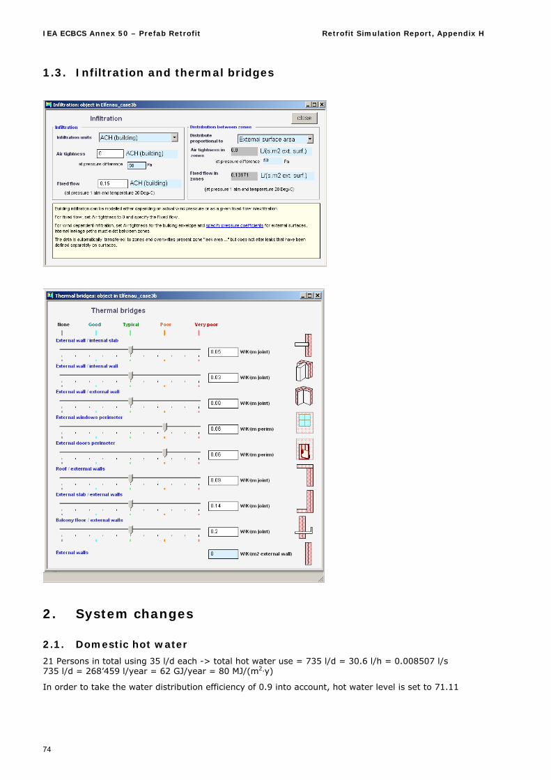
IEA ECBCS Annex 50 – Prefab Retrofit Retrofit Simulation Report, Appendix H
74
1.3. Infiltration and thermal bridges
2. System changes
2.1. Domestic hot water
21 Persons in total using 35 l/d each -> total hot water use = 735 l/d = 30.6 l/h = 0.008507 l/s 735 l/d = 268’459 l/year = 62 GJ/year = 80 MJ/(m2·y)
In order to take the water distribution efficiency of 0.9 into account, hot water level is set to 71.11
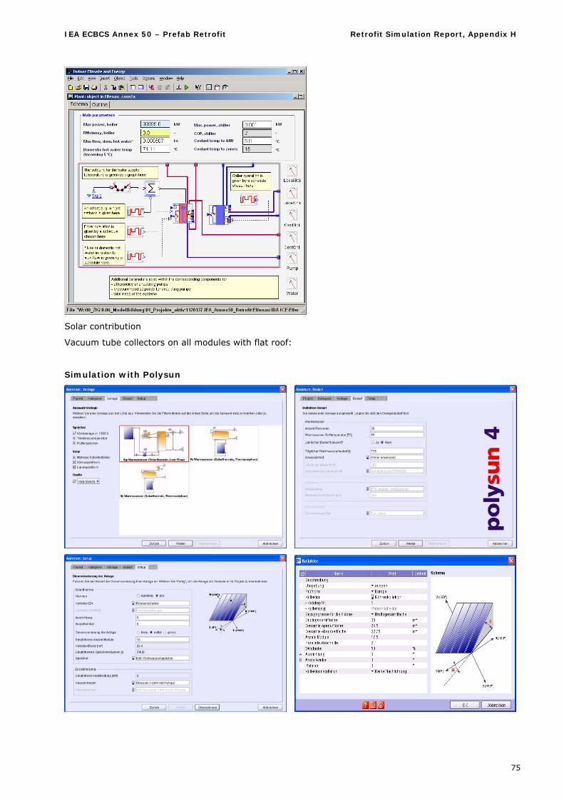
IEA ECBCS Annex 50 – Prefab Retrofit Retrofit Simulation Report, Appendix H
75
Solar contribution
Vacuum tube collectors on all modules with flat roof:
Simulation with Polysun
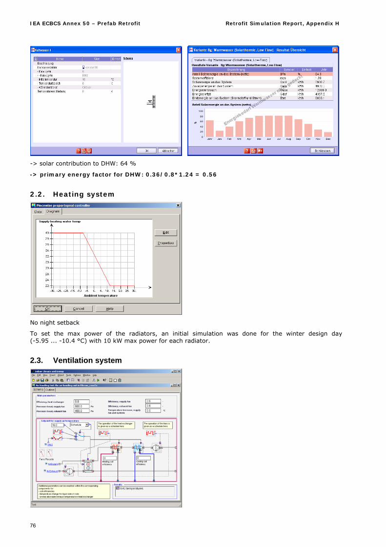
IEA ECBCS Annex 50 – Prefab Retrofit Retrofit Simulation Report, Appendix H
76
-> solar contribution to DHW: 64 %
-> primary energy factor for DHW: 0.36/0.8*1.24 = 0.56
2.2. Heating system
No night setback
To set the max power of the radiators, an initial simulation was done for the winter design day (-5.95 ... -10.4 °C) with 10 kW max power for each radiator.
2.3. Ventilation system
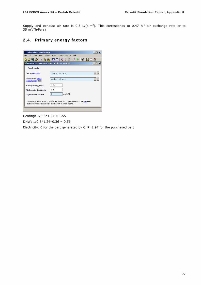
IEA ECBCS Annex 50 – Prefab Retrofit Retrofit Simulation Report, Appendix H
77
Supply and exhaust air rate is 0.3 L/(s·m2). This corresponds to 0.47 h-1 air exchange rate or to 35 m3/(h·Pers)
2.4. Primary energy factors
Heating: 1/0.8*1.24 = 1.55
DHW: 1/0.8*1.24*0.36 = 0.56
Electricity: 0 for the part generated by CHP, 2.97 for the purchased part
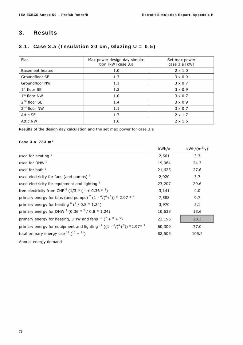
IEA ECBCS Annex 50 – Prefab Retrofit Retrofit Simulation Report, Appendix H
78
3. Results
3.1. Case 3.a (Insulation 20 cm, Glazing U = 0.5) Flat Max power design day simula-
tion [kW] case 3.a Set max power case 3.a [kW]
Basement heated 1.0 2 x 1.0
Groundfloor SE 1.3 3 x 0.9
Groundfloor NW 1.1 3 x 0.7
1st floor SE 1.3 3 x 0.9
1st floor NW 1.0 3 x 0.7
2nd floor SE 1.4 3 x 0.9
2nd floor NW 1.1 3 x 0.7
Attic SE 1.7 2 x 1.7
Attic NW 1.6 2 x 1.6
Results of the design day calculation and the set max power for case 3.a
Case 3.a 783 m2
kWh/a kWh/(m2·y)
used for heating 1 2,561 3.3
used for DHW 2 19,064 24.3
used for both 3 21,625 27.6
used electricity for fans (and pumps) 4 2,920 3.7
used electricity for equipment and lighting 5 23,207 29.6
free electricity from CHP 6 (1/3 * ( 1 + 0.36 * 2) 3,141 4.0
primary energy for fans (and pumps) 7 (1 - 6/(4+5)) * 2.97 * 4 7,588 9.7
primary energy for heating 8 (1 / 0.8 * 1.24) 3,970 5.1
primary energy for DHW 9 (0.36 * 2 / 0.8 * 1.24) 10,638 13.6
primary energy for heating, DHW and fans 10 (7 + 8 + 9) 22,196 28.3
primary energy for equipment and lighting 11 ((1 - 6/(4+5)) *2.97* 5 60,309 77.0
total primary energy use 12 (10 + 11) 82,505 105.4
Annual energy demand
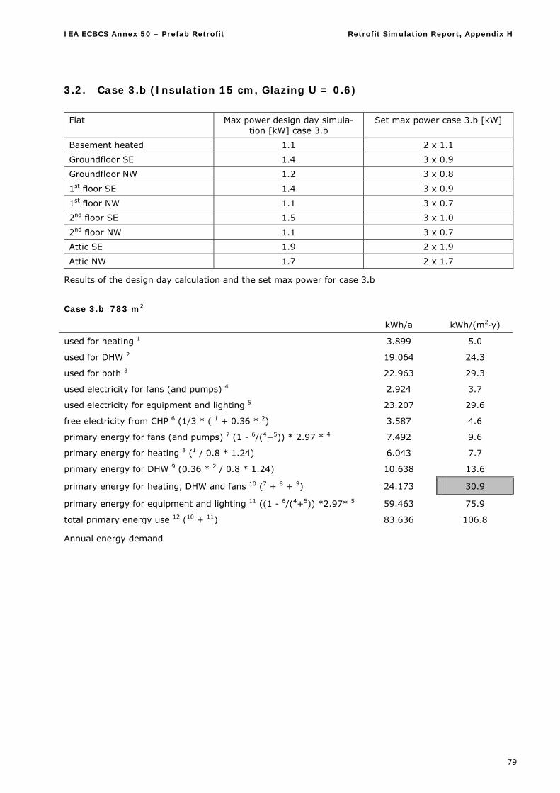
IEA ECBCS Annex 50 – Prefab Retrofit Retrofit Simulation Report, Appendix H
79
3.2. Case 3.b (Insulation 15 cm, Glazing U = 0.6)
Flat Max power design day simula-
tion [kW] case 3.b Set max power case 3.b [kW]
Basement heated 1.1 2 x 1.1
Groundfloor SE 1.4 3 x 0.9
Groundfloor NW 1.2 3 x 0.8
1st floor SE 1.4 3 x 0.9
1st floor NW 1.1 3 x 0.7
2nd floor SE 1.5 3 x 1.0
2nd floor NW 1.1 3 x 0.7
Attic SE 1.9 2 x 1.9
Attic NW 1.7 2 x 1.7
Results of the design day calculation and the set max power for case 3.b
Case 3.b 783 m2
kWh/a kWh/(m2·y)
used for heating 1 3.899 5.0
used for DHW 2 19.064 24.3
used for both 3 22.963 29.3
used electricity for fans (and pumps) 4 2.924 3.7
used electricity for equipment and lighting 5 23.207 29.6
free electricity from CHP 6 (1/3 * ( 1 + 0.36 * 2) 3.587 4.6
primary energy for fans (and pumps) 7 (1 - 6/(4+5)) * 2.97 * 4 7.492 9.6
primary energy for heating 8 (1 / 0.8 * 1.24) 6.043 7.7
primary energy for DHW 9 (0.36 * 2 / 0.8 * 1.24) 10.638 13.6
primary energy for heating, DHW and fans 10 (7 + 8 + 9) 24.173 30.9
primary energy for equipment and lighting 11 ((1 - 6/(4+5)) *2.97* 5 59.463 75.9
total primary energy use 12 (10 + 11) 83.636 106.8
Annual energy demand
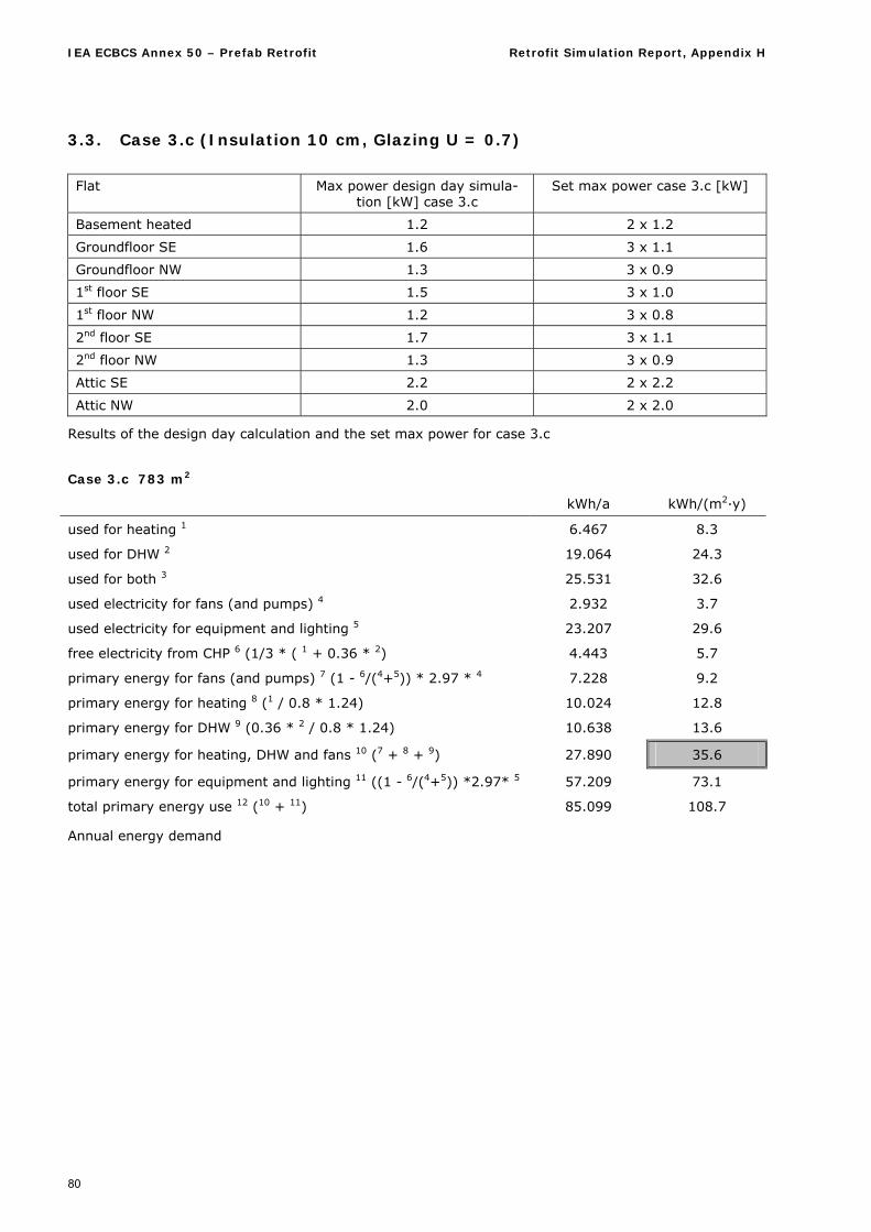
IEA ECBCS Annex 50 – Prefab Retrofit Retrofit Simulation Report, Appendix H
80
3.3. Case 3.c (Insulation 10 cm, Glazing U = 0.7)
Flat Max power design day simula-
tion [kW] case 3.c Set max power case 3.c [kW]
Basement heated 1.2 2 x 1.2
Groundfloor SE 1.6 3 x 1.1
Groundfloor NW 1.3 3 x 0.9
1st floor SE 1.5 3 x 1.0
1st floor NW 1.2 3 x 0.8
2nd floor SE 1.7 3 x 1.1
2nd floor NW 1.3 3 x 0.9
Attic SE 2.2 2 x 2.2
Attic NW 2.0 2 x 2.0
Results of the design day calculation and the set max power for case 3.c
Case 3.c 783 m2
kWh/a kWh/(m2·y)
used for heating 1 6.467 8.3
used for DHW 2 19.064 24.3
used for both 3 25.531 32.6
used electricity for fans (and pumps) 4 2.932 3.7
used electricity for equipment and lighting 5 23.207 29.6
free electricity from CHP 6 (1/3 * ( 1 + 0.36 * 2) 4.443 5.7
primary energy for fans (and pumps) 7 (1 - 6/(4+5)) * 2.97 * 4 7.228 9.2
primary energy for heating 8 (1 / 0.8 * 1.24) 10.024 12.8
primary energy for DHW 9 (0.36 * 2 / 0.8 * 1.24) 10.638 13.6
primary energy for heating, DHW and fans 10 (7 + 8 + 9) 27.890 35.6
primary energy for equipment and lighting 11 ((1 - 6/(4+5)) *2.97* 5 57.209 73.1
total primary energy use 12 (10 + 11) 85.099 108.7
Annual energy demand
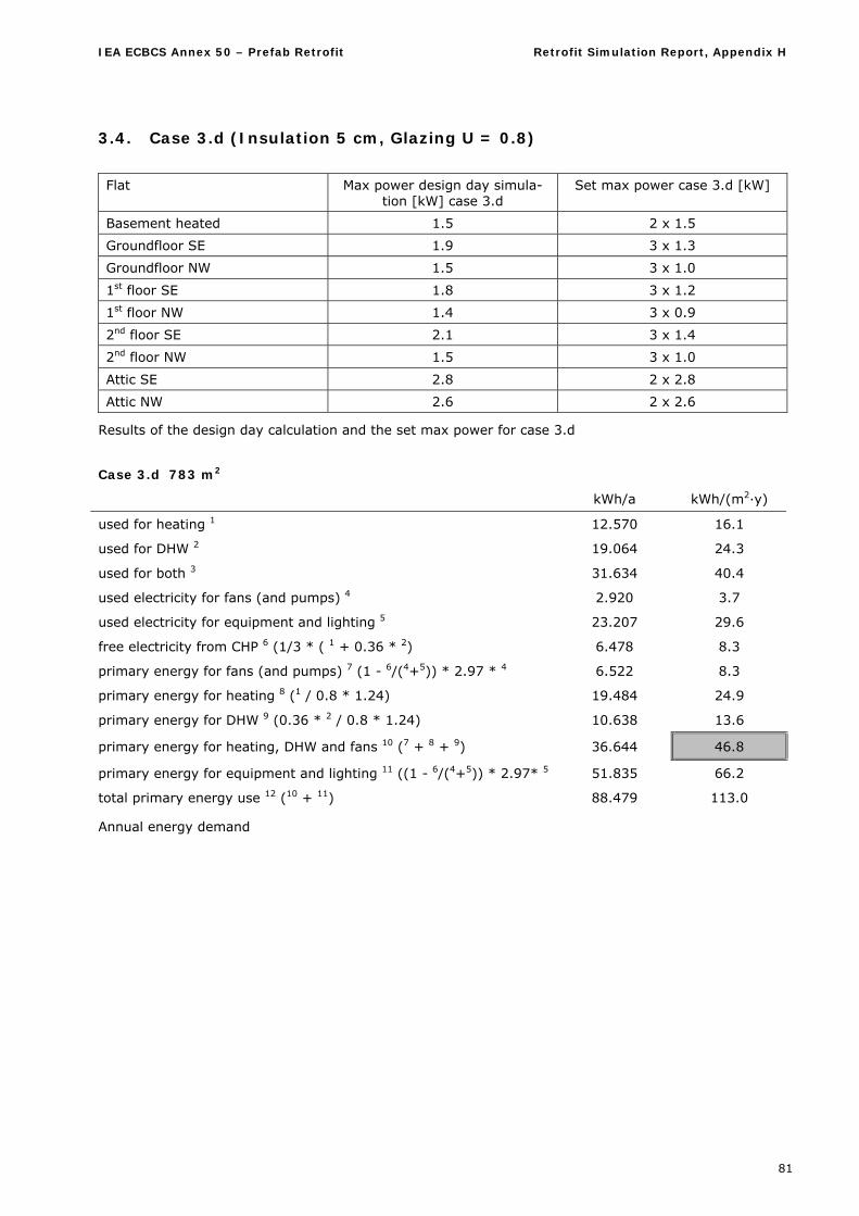
IEA ECBCS Annex 50 – Prefab Retrofit Retrofit Simulation Report, Appendix H
81
3.4. Case 3.d (Insulation 5 cm, Glazing U = 0.8)
Flat Max power design day simula-
tion [kW] case 3.d Set max power case 3.d [kW]
Basement heated 1.5 2 x 1.5
Groundfloor SE 1.9 3 x 1.3
Groundfloor NW 1.5 3 x 1.0
1st floor SE 1.8 3 x 1.2
1st floor NW 1.4 3 x 0.9
2nd floor SE 2.1 3 x 1.4
2nd floor NW 1.5 3 x 1.0
Attic SE 2.8 2 x 2.8
Attic NW 2.6 2 x 2.6
Results of the design day calculation and the set max power for case 3.d
Case 3.d 783 m2
kWh/a kWh/(m2·y)
used for heating 1 12.570 16.1
used for DHW 2 19.064 24.3
used for both 3 31.634 40.4
used electricity for fans (and pumps) 4 2.920 3.7
used electricity for equipment and lighting 5 23.207 29.6
free electricity from CHP 6 (1/3 * ( 1 + 0.36 * 2) 6.478 8.3
primary energy for fans (and pumps) 7 (1 - 6/(4+5)) * 2.97 * 4 6.522 8.3
primary energy for heating 8 (1 / 0.8 * 1.24) 19.484 24.9
primary energy for DHW 9 (0.36 * 2 / 0.8 * 1.24) 10.638 13.6
primary energy for heating, DHW and fans 10 (7 + 8 + 9) 36.644 46.8
primary energy for equipment and lighting 11 ((1 - 6/(4+5)) * 2.97* 5 51.835 66.2
total primary energy use 12 (10 + 11) 88.479 113.0
Annual energy demand
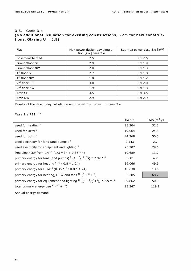
IEA ECBCS Annex 50 – Prefab Retrofit Retrofit Simulation Report, Appendix H
82
3.5. Case 3.e (No additional insulation for existing constructions, 5 cm for new construc-tions, Glazing U = 0.8)
Flat Max power design day simula-
tion [kW] case 3.e Set max power case 3.e [kW]
Basement heated 2.5 2 x 2.5
Groundfloor SE 2.9 3 x 1.9
Groundfloor NW 2.0 3 x 1.3
1st floor SE 2.7 3 x 1.8
1st floor NW 1.8 3 x 1.2
2nd floor SE 3.0 3 x 2.0
2nd floor NW 1.9 3 x 1.3
Attic SE 3.5 2 x 3.5
Attic NW 2.9 2 x 2.9
Results of the design day calculation and the set max power for case 3.e
Case 3.e 783 m2
kWh/a kWh/(m2·y)
used for heating 1 25.204 32.2
used for DHW 2 19.064 24.3
used for both 3 44.268 56.5
used electricity for fans (and pumps) 4 2.143 2.7
used electricity for equipment and lighting 5 23.207 29.6
free electricity from CHP 6 (1/3 * ( 1 + 0.36 * 2) 10.689 13.7
primary energy for fans (and pumps) 7 (1 - 6/(4+5)) * 2.97 * 4 3.681 4.7
primary energy for heating 8 (1 / 0.8 * 1.24) 39.066 49.9
primary energy for DHW 9 (0.36 * 2 / 0.8 * 1.24) 10.638 13.6
primary energy for heating, DHW and fans 10 (7 + 8 + 9) 53.385 68.2
primary energy for equipment and lighting 11 ((1 - 6/(4+5)) * 2.97* 5 39.862 50.9
total primary energy use 12 (10 + 11) 93.247 119.1
Annual energy demand
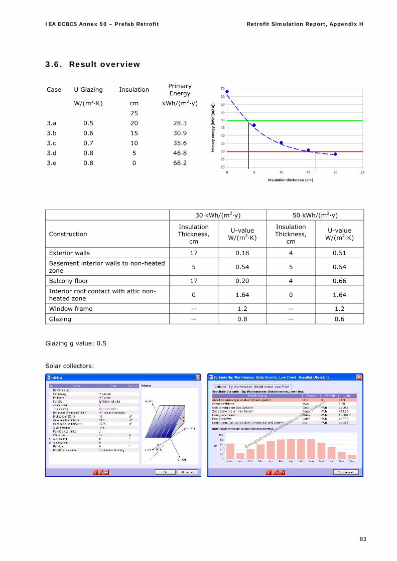
IEA ECBCS Annex 50 – Prefab Retrofit Retrofit Simulation Report, Appendix H
83
3.6. Result overview
20
25
30
35
40
45
50
55
60
65
70
0 5 10 15 20 25
Insulation thickness (cm)
Pri
mar
y en
erg
y (k
Wh
/(m
2 a)
)
30 kWh/(m2·y) 50 kWh/(m2·y)
Construction Insulation Thickness,
cm
U-value W/(m2·K)
Insulation Thickness,
cm
U-value W/(m2·K)
Exterior walls 17 0.18 4 0.51
Basement interior walls to non-heated zone
5 0.54 5 0.54
Balcony floor 17 0.20 4 0.66
Interior roof contact with attic non-heated zone
0 1.64 0 1.64
Window frame -- 1.2 -- 1.2
Glazing -- 0.8 -- 0.6
Glazing g value: 0.5
Solar collectors:
Case U Glazing Insulation Primary Energy
W/(m2·K) cm kWh/(m2·y)
25
3.a 0.5 20 28.3
3.b 0.6 15 30.9
3.c 0.7 10 35.6
3.d 0.8 5 46.8
3.e 0.8 0 68.2
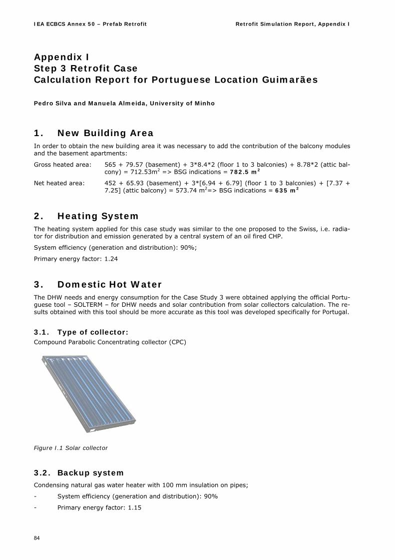
IEA ECBCS Annex 50 – Prefab Retrofit Retrofit Simulation Report, Appendix I
84
Appendix I Step 3 Retrofit Case Calculation Report for Portuguese Location Guimarães Pedro Silva and Manuela Almeida, University of Minho
1. New Building Area In order to obtain the new building area it was necessary to add the contribution of the balcony modules and the basement apartments:
Gross heated area: 565 + 79.57 (basement) + 3*8.4*2 (floor 1 to 3 balconies) + 8.78*2 (attic bal-cony) = 712.53m2 => BSG indications = 782.5 m2
Net heated area: 452 + 65.93 (basement) + 3*[6.94 + 6.79] (floor 1 to 3 balconies) + [7.37 + 7.25] (attic balcony) = 573.74 m2=> BSG indications = 635 m2
2. Heating System The heating system applied for this case study was similar to the one proposed to the Swiss, i.e. radia-tor for distribution and emission generated by a central system of an oil fired CHP.
System efficiency (generation and distribution): 90%;
Primary energy factor: 1.24
3. Domestic Hot Water The DHW needs and energy consumption for the Case Study 3 were obtained applying the official Portu-guese tool – SOLTERM – for DHW needs and solar contribution from solar collectors calculation. The re-sults obtained with this tool should be more accurate as this tool was developed specifically for Portugal.
3.1. Type of collector: Compound Parabolic Concentrating collector (CPC)
Figure I.1 Solar collector
3.2. Backup system Condensing natural gas water heater with 100 mm insulation on pipes;
- System efficiency (generation and distribution): 90%
- Primary energy factor: 1.15
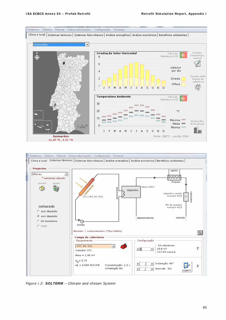
IEA ECBCS Annex 50 – Prefab Retrofit Retrofit Simulation Report, Appendix I
85
Figure I.2: SOLTERM – Climate and chosen System
IEA ECBCS Annex 50 – Prefab Retrofit Retrofit Simulation Report, Appendix I
86
3.3. Retrofit to achieve 30 kWh/(m2·y)
Area: 1.98 m2 (10 collectors) = 19.8 m2
Total solar contribution for domestic hot water obtained from SOLTERM: 9700 kWh
Table I.1: Allocation of solar gains by apartment:
Occupants per apart-
ment Total nº occupants
Solar Gains for DHW (kWh)
T0 – basement 1 2 404.167
T1 – attic 2 4 808.33
T2 – floor 1, 2 and 3 3 18 1212.15
Total _ 24 9700
3.4. Retrofit to achieve 50 kWh/(m2·y)
Area: 1.98 m2 (8 collectors) = 15.84 m2
Total solar contribution for domestic hot water obtained from SOLTERM: 8000 kWh
Table I.2: Allocation of solar gains by Apartment:
Occupants per apart-
ment Total nº occupants
Solar Gains for DHW (kWh)
T0 – basement 1 2 333.33
T1 – attic 2 4 666.67
T2 – floor 1, 2 and 3 3 18 1000
Total _ 24 8000
4. Glazings
4.1. Retrofit to achieve 30 kWh/(m2·y) Saint-Gobain Climaplus Solar Control (double glass) U-Value = 1.1 W/(m²·K)
gs = 0.45
Introduction of exterior venetian blinds gs = 0.05
4.2. Retrofit to achieve 50 kWh/(m2·y) Saint-Gobain Clima Solar Control (double glass) U-Value = 2.1 W/(m²·K)
gs = 0.45
Introduction of exterior venetian blinds gs = 0.05
5. Building Envelope
5.1. Insulation to achieve 30 kWh/(m2·y) Exterior Walls: EPS – 15cm
U-Value = 0.23 W/(m²·K)
Interior walls XPS - 4 cm
(Basement interior walls to non-heated zone): U-Value = 0.67 W/(m²·K)
Balcony floor: XPS - 4 cm
U-Value = 0.68 W/(m²·K)
IEA ECBCS Annex 50 – Prefab Retrofit Retrofit Simulation Report, Appendix I
87
Interior roof XPS - 4 cm
(in contact with attic non-heated zone): U-Value = 0.68 W/(m²·K)
5.2. Insulation to achieve 50 kWh/(m2·y)
Exterior walls: EPS – 7 cm
U-Value = 0.44 W/(m²·K)
6. Heating Needs Calculation The Case Study 3 was simulated using the DesignBuilder simulation tool to produce the model and the EnergyPlus simulation tool to calculate the energy needs. Following this methodology there were calcu-lated the useful and delivered energy needs.
As required, all the necessary inputs were the ones given to us in the Specifications Document and simulated in Guimarães, a Potuguese city located in the north of Portugal, 50 km away from the sea (GPS coordenates - latitude: 41.4418°; longitude: - 8.29563), thus a climatic file was also constructed: Guimaraes04_UM_Dez03_3DOE2.epw.
However during the simulations there were encountered some modelling difficulties:
The ventilation system modelling was very complex and several problems were found (will be discussed afterwards);
It was not possible to edit the model created during Case Study 1 and 2, due to DesignBuilder limitations, in order to introduce the proposed modifications, thus a new model had to be created;
Due to lack of input data definition, the heating system was not modelled in EnergyPlus. Instead it was used the “Purchased Air” option in order to obtain the building energy needs, and after the necessary effiencies where applied in the excel worksheet.
6.1. Ventilation system
Several problems occurred when trying to simulate the Heating Recovery Ventilation unit in the “Elf-enau” building with EnergyPlus:
Lack of input data; No defined schedules for fans or HRV unit; EnergyPlus results when including the heat recovery ventilation system simulation presented,
systematically, high values of heating needs, which were related to an improperly working system model;
Wide range of results from the simulation;
Thus, the ventilation system was calculated using the Portuguese Thermal Regulation methodology, considering 1 ACH in every heated zone, simulating a balanced ventilation system that can guarantee no infiltrations =>
( ins - ext)/V > 0.5
It was considered that the electric consumption of the ventilation system would be distributed by apartment and would count for 45W. Then, the electric consumption of each Ventilator of each apart-ment would be:
P = Pv*24h*0.03*M
With:
Pv – power – 45 W;
M – Heating or cooling season months.
Then:
PHeating Season = 45*24*0.03*7 = 226.8 kWh
PCooling Season = 45*24*0.03*4 = 129.6 kWh
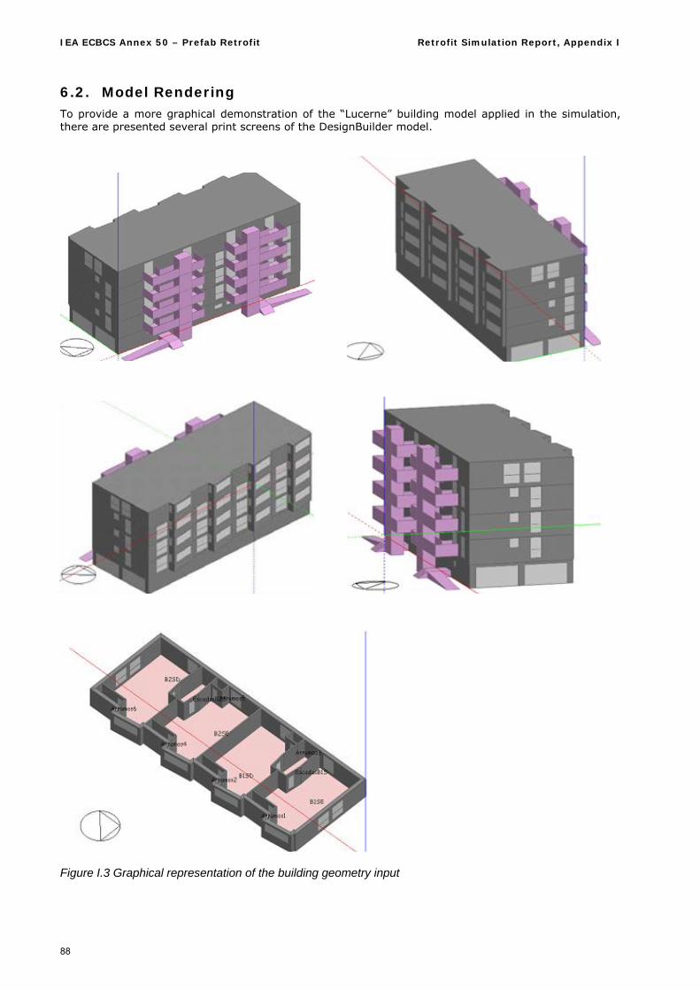
IEA ECBCS Annex 50 – Prefab Retrofit Retrofit Simulation Report, Appendix I
88
6.2. Model Rendering To provide a more graphical demonstration of the “Lucerne” building model applied in the simulation, there are presented several print screens of the DesignBuilder model.
Figure I.3 Graphical representation of the building geometry input
IEA ECBCS Annex 50 – Prefab Retrofit Retrofit Simulation Report, Appendix I
89
7. Results Case Study 3 - 30 kWh/(m2·y)
Building Useful Heating Energy Demand (including ventilators consumption):
- 9.5 kWh/(m2·y)
Building Useful DHW Energy Demand:
- 16.8 kWh/(m2·y)
Building Useful Total Energy Demand = 26.3 kWh/(m2·y)
Building Delivered Heating Energy Demand:
- 13.0 kWh/(m2·y)
Building Delivered DHW Energy Demand:
- 21.5 kWh/(m2·y)
Building Delivered Total Energy Demand = 34.5 kWh/(m2·y)
8. Results Case Study 3 - 50 kWh/(m²·y)
Building Useful Heating Energy Demand:
- 15.6 kWh/(m2·y)
Building Useful DHW Energy Demand:
- 20.5 kWh/(m2·y)
Building Useful Total Energy Demand = 36.1 kWh/(m2·y)
Building Heating Energy Demand:
- 21.5 kWh/(m2·y)
Building Delivered DHW Energy Demand:
- 26.2 kWh/(m2·y)
Building Delivered Total Energy Demand = 47.7 kWh/(m2·y)
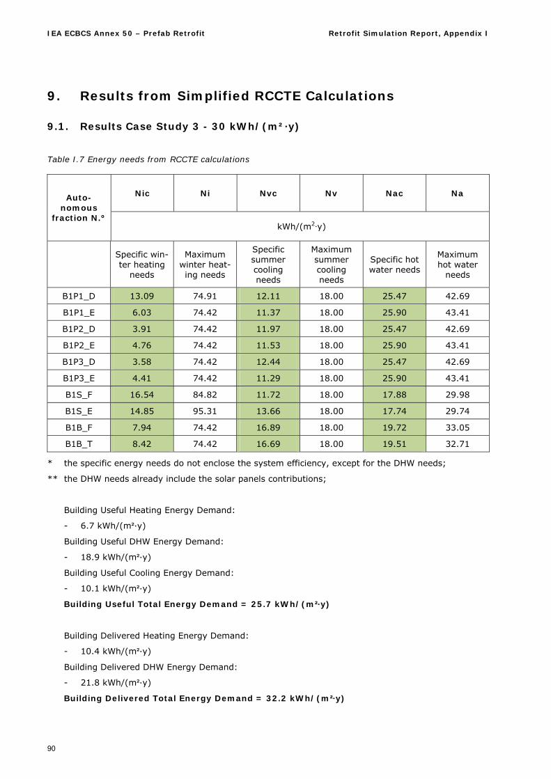
IEA ECBCS Annex 50 – Prefab Retrofit Retrofit Simulation Report, Appendix I
90
9. Results from Simplified RCCTE Calculations
9.1. Results Case Study 3 - 30 kWh/(m²·y)
Table I.7 Energy needs from RCCTE calculations
Nic Ni Nvc Nv Nac Na Auto-nomous
fraction N.º kWh/(m2·y)
Specific win-ter heating
needs
Maximum winter heat-ing needs
Specific summer cooling needs
Maximum summer cooling needs
Specific hot water needs
Maximum hot water
needs
B1P1_D 13.09 74.91 12.11 18.00 25.47 42.69
B1P1_E 6.03 74.42 11.37 18.00 25.90 43.41
B1P2_D 3.91 74.42 11.97 18.00 25.47 42.69
B1P2_E 4.76 74.42 11.53 18.00 25.90 43.41
B1P3_D 3.58 74.42 12.44 18.00 25.47 42.69
B1P3_E 4.41 74.42 11.29 18.00 25.90 43.41
B1S_F 16.54 84.82 11.72 18.00 17.88 29.98
B1S_E 14.85 95.31 13.66 18.00 17.74 29.74
B1B_F 7.94 74.42 16.89 18.00 19.72 33.05
B1B_T 8.42 74.42 16.69 18.00 19.51 32.71
* the specific energy needs do not enclose the system efficiency, except for the DHW needs;
** the DHW needs already include the solar panels contributions;
Building Useful Heating Energy Demand:
- 6.7 kWh/(m²·y)
Building Useful DHW Energy Demand:
- 18.9 kWh/(m²·y)
Building Useful Cooling Energy Demand:
- 10.1 kWh/(m²·y)
Building Useful Total Energy Demand = 25.7 kWh/(m²·y)
Building Delivered Heating Energy Demand:
- 10.4 kWh/(m²·y)
Building Delivered DHW Energy Demand:
- 21.8 kWh/(m²·y)
Building Delivered Total Energy Demand = 32.2 kWh/(m²·y)
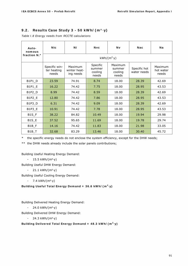
IEA ECBCS Annex 50 – Prefab Retrofit Retrofit Simulation Report, Appendix I
91
9.2. Results Case Study 3 - 50 kWh/(m²·y)
Table I.8 Energy needs from RCCTE calculations
Nic Ni Nvc Nv Nac Na Auto-nomous
fraction N.º kWh/(m2·y)
Specific win-ter heating
needs
Maximum winter heat-ing needs
Specific summer cooling needs
Maximum summer cooling needs
Specific hot water needs
Maximum hot water
needs
B1P1_D 23.59 74.91 8.74 18.00 28.39 42.69
B1P1_E 16.22 74.42 7.75 18.00 28.95 43.53
B1P2_D 8.99 74.42 8.59 18.00 28.39 42.69
B1P2_E 12.80 74.42 7.86 18.00 28.95 43.53
B1P3_D 6.31 74.42 9.09 18.00 28.39 42.69
B1P3_E 10.91 74.42 7.78 18.00 28.95 43.53
B1S_F 38.22 84.82 10.49 18.00 19.94 29.98
B1S_E 37.52 95.65 11.69 18.00 19.78 29.74
B1B_F 14.16 74.42 11.83 18.00 21.98 33.05
B1B_T 32.68 83.29 13.46 18.00 30.40 45.72
* the specific energy needs do not enclose the system efficiency, except for the DHW needs;
** the DHW needs already include the solar panels contributions;
Building Useful Heating Energy Demand:
- 15.5 kWh/(m²·y)
Building Useful DHW Energy Demand:
- 21.1 kWh/(m²·y)
Building Useful Cooling Energy Demand:
- 7.4 kWh/(m²·y)
Building Useful Total Energy Demand = 36.6 kWh/(m2·y)
Building Delivered Heating Energy Demand:
- 24.0 kWh/(m²·y)
Building Delivered DHW Energy Demand:
- 24.3 kWh/(m²·y)
Building Delivered Total Energy Demand = 48.3 kWh/(m2·y)

IEA ECBCS Annex 50Prefabricated Systems for Low Energy
Renovation of Residential Buildings
RetrofitSimulation Report
March 2011
IEA E
CBC
S A
nnex
50 -
Ret
rofi
t Si
mula
tion
Rep
ort
AEE - Institute for Sustainable Technologies (AEE-INTEC), Austria
Enviros s.r.o., Czech RepublicBrno University of Technology, Institute of Building Services, Czech Republic
Centre scientifique et technique du bâtiment CSTB, FranceSaint-Gobain Isover, E3 Performances / ArcelorMittal, FranceEDF, AETIC, ALDES, Vinci Constructions, France
Energy Research Centre of the Netherlands ECN, Netherlands
Porto University, Faculty of Engineering, PortugalUniversity of Minho, Civil Engineering Department, Construction and Technology Group, Portugal
CNA Arkitektkontor AB, SwedenEnergy and Building Design, Lund Institute of Technology, Sweden
Lucerne University of Applied Sciences and Arts, Technology and Architecture, SwitzerlandUniversity of Applied Sciences Northwestern Switzerland, School of Architecture,Civil Engineering and Geomatics, SwitzerlandSwiss Federal Laboratories for Materials Science and Technology Empa,Building Science and Technology Laboratory, Switzerland
Research Partners:
Published by: