resources/fib... · subject to priorities defined by the steering committee and the praesidium, the...
TRANSCRIPT
t: .--Q) --
Nuclear containments
Nuclear containments
State-of-art report prepared by
Task Group Containment Structures
(fomler FIP Commission 7)
June 2001
Subject to priorities defined by the Steering Committee and the Praesidium, the results of fib's work in Commissions and Task Groups are published in a continuously numbered series of technical publications called 'Bulletins'. The following categories are used:
category minimum approval procedure required prior to publication
Technical Report approved by a Task Group and the Chairpersons of the Commission State-of-Art report approved by a Commission Manual or approved by the Steering Committee offib or its Publication Board Guide (to good practice) Recommendation approved by the Council offib Model Code approved by the General Assembly of fib
Any publication not hewing met the above requirements will be clearly identified as preliminary draft.
This Bulletin N° 13 has been approved as a fib State-of-art report in autumn 2000 by fib Commission I Structures
The report \vas drafted by fib Task Group 1.3 Containment structures:
Jack Picaut* (Convenor, France)
Members: Jacques Chataigner* (France), Daniele Chauvel* (France), RUdiger Danisch* (Germany),
Sten Forstrom* (Sweden), Takashi Kuroda* (Japan), Jean-Mathieu Rambach* (France), Eric Mathet* (OECD)
Further members and invited experts: Jean-Louis Costaz (France), James Costello (USA), Luc de Mameffe (Belgium), Medhat Elgohary (Canada), Jean-Philippe Fuzier (France), Subhash Joglekar (India), Julij Klimov (Ukraine), Roger Lacroix (France), Peter Lenkei (Hungary), Alex Miller (OECD), Dan Naus (USA), Sergej Nefedov (Russia), Joseph Nemet (Austria), Umesh Rajeshirke (India), Klaus Schimmelpfennig (Germany). Claude Seni (Canada), Leslie Smith (Great Britain), Liu Wei (China)
* Main contributors to this publication (members urthe Editorial Board created \vithin TG 1.3)
Full affiliation details of Task Groups members may he found in the fib Directory.
Cover picture: Nuclear Power Plant Paluel (Normandy - France. 1300 MW PWR; photo: Pierre Beranger)
© federation internationale du beton (jib), 200 I
Although the International Federation for Structural Concrete fib - federation intcrn<.llionale du betoll - created from CEB and FIP, does its best to ensure that any infonnation given is accurate, no liability or responsibility oj' any kind (including liability for negligence) is accepted in this respect by the organisation, its members, servants or agents.
All rights reserved. No part of this publication may be reproduced, modified, translated, stored in a retrieval system, or transmitted in any form or by any means, electronic, mechanical, photocopying, recording, or otherwise, without prior written permission.
First published 2001 by the International Federation for Structural Concrete (fib) Post address: Case Postale 88, CH-l 015 Lausanne, Switzerland Street address: Federal Institute of Technology Lausanne - EPFL, Departement Genie Civil Tel (+41.21) 693 2747, Fax (+41.21) 693 5884, E-mail [email protected], web http://fib.eptl.ch
ISSN 1562-3610 ISBN 2-88394-053-3 Printed by Sprint-Digital-Druck Stuttgart
Copyright fib, all rights reserved. This PDF copy of fib Bulletin 13 is intended for use and/or distribution only by National Member Groups of fib.
FOREWORD
The former FIP (Federation Internationale de la Precontrainte) had establ ished a
specialized Comtnission 7 Concrete pressure vessels and containments. As early as 1996, the
necessity of updating the June 1978 FIP State-of-art-report on Containments fhr Nuclear
Power Plants (NPPs) had been discussed within this COlnmission.
After the merger of FIP with CEB (Comite Euro-International du Beton) into fib
(federation internationale du beton - international federation for structural concrete) had taken
place in 1998, the activities of FIP Comtnission 7 were continued by a new fib Task-Group
l.3 Containment structures of Jib Comlnission 1 Structures. The decision to update the 1978
report was kept with the intention to give a broad and well illustrated review of ex isting NPP
containments as the most characteristic and complex building of nuclear power plants.
Following the description of containments for different reactor systetns the state-of-art
report includes considerations on safety as the basic purpose of the containment, which
underlies all design and construction aspects and necessitates a strict monitoring and
inspection program during the whole life of the structure.
Regulatory requirements and their evolution as well as recent developments, conceptual
and technological, are presented.
The report is complemented by t\'\I'O annexes on CD ROM giving some general and more
detailed information on NPP containments.
This vlork has been achieved during the years 1999 and 2000 thanks to the participation of
members of fib Commission I and particularly of its Task Group 1.3, involving also further
invited experts in the nuclear field from tnany countries all over the world.
Paris, December 2000
Jack Picaut Jean-Franc;ois Klein Chairman of former FIP Commission 7 Chairman offib Commission 1 Strllctures
Convenor offib Task Group 1.3 Nllclear containments
fib Bulletin /3.· N/lc:lem' containments iii
Copyright fib, all rights reserved. This PDF copy of fib Bulletin 13 is intended for use and/or distribution only by National Member Groups of fib.
Contents
1 Introduction 1.1 General infonnation 1.2 Scope of the state-of-art report on concrete containments 1.3 Some general information on nuclear power plants (NPP)
2 Containments for different reactor types 2.1 General 2.2 The different types of recent Nuclear Power Plants (NPP) 2.3 Preliminary presentation of containments associated with the different
reactor systems
3 Description of the different types of containments 3.1 General presentation of recent containments 3.2 Detailed presentation of recent containments
4 Safety 4.1 General 4.2 Safety organization 4.3 Safety reports and regulations 4.4 The concept of "in depth defence" 4.5 The probabilistic safety approach 4.6 The observance of safety rules for the containment 4.7 Safety as a permanent quest: reassessment of the plant, Periodic Safety Reviews
(PSR) [GEeD - NEA, Jan 200 I] 4.8 Probability safety assessment of the containment
5 The execution of a project 5.1 General 5.2 The different participants in a project 5.3 The different stages in the development of a project 5.4 Design for export projects
6 The main factors governing design 6.1 The design parameters and mechanical properties of materials 6.2 The loads (or actions) exerted on the containment 6.3 The applied regulations and codes 6.4 Typical combinations of actions and design criteria 6.5 International harmonisation of general requirements, general codes and
particular codes 6.6 The impact on design of the different factors evoked previously
7 The construction materials for the containnlent 7.1 General 7.2 Concrete 7.3 The steel liner and penetrations
2 2
7 7
9
19 19
27 28 28 29 31 32
33 35
35 36 36 39
41 43 45 48
49 51
57 57 58
Copyright fib, all rights reserved. This PDF copy of fib Bulletin 13 is intended for use and/or distribution only by National Member Groups of fib.
7.4 Reinforcing steel bars 58 7.5 Prestressing 59
8 Construction methods for the containment 8.1 General 67
8.2 The basemat and foundations 67 8.3 The inner containment wall 68 8.4 The inner containment dome 73 8.5 The external containment 73 8.6 The prestressing operations 75
9 Some considerations on recent developments 9.1 Conceptual aspects 79 9.2 Some new concepts in design 80 9.3 Some technological aspects and ne\\l materials 87 9.4 Large scale models 90
to Monitoring and inspection program of containments 10.1 General 101 10.2 Codes and standards 101 10.3 Initial Structural Integrity Test (ISIT) 102 10.4 Pre-operational leakage test 105 10.5 In service surveillance of the structural integrity 107 10.6 In service surveillance leakage tests 111 10.7 Some typical results of structural deformation obtained by monitoring 112
11 Possible incidental events requiring particular care in design, construction and monitoring of NPP containnlents 11.1 Preamble 115 11.2 Change in design loads
11.3 Prestressing tendons
11.4 Liner and liner plates 11.5 Design problems 11.6 Leakage tightness of the containment 11.7 Degradation of concrete strength with tinlC
References
Annex (on CD-ROl\l 'Annex Bulletin 13' - see cover page 3)
• General data on nuclear power plant containments built since 1972
• Detailed infornlation on six typical recent containments
fib Bulletin 13
115
I IS 115 116 116 116
It7
v

Copyright fib, all rights reserved. This PDF copy of fib Bulletin 13 is intended for use and/or distribution only by National Member Groups of fib.
General
NPP
NSSS
ABBREVIATIONS
Nuclear Pov.,'er Plant
Nuclear Steam Supply System
PCCV Prestressed Concrete Containment Vessel
RCCV: Reinforced Concrete Containment Vessel
RC Reinforced Concrete
PC Prestressed concrete
Types of nuclear power plants
ABWR: Advanced Boiling Water Reactor
AGR Advanced Gas-cooled Reactor
BWR Boiling Water Reactor
EPR European Pressurized Reactor
FBR Fast Breeder Reactor
HTR High Temperature Reactor
PHWR (CANDU): Pressurized Heavy Water Reactor (Canada Deuterium UraniUln)
PWR : Pressurized Water Reactor
RBMK Channel Reactor of Large Capacity
VVER: Pressurized water Reactor
Operators and constructors
ABB Asea Brown Boveri
AECL Atomic Energy of Canada Limited
BE British Energy
EDF
KWU
NSSS
Electricite de France
Kra ftwerkun ion
Nuclear Steam System Supplier
Codes and standards, safety and regulatory organizations,
ACI Alnerican Concrete Institute
AU Architectural Institute of Japan
ASCE American Society of Civil Engineers
ASME: American Society of Mechanical Engineers
BAEL Beton anne aux Etats Limites (French code for RC)
BPEL Beton Precontraint aux Etats Limites (French code for PC)
BS British Standards
CEB Comite Europeen du Beton
CFR Code of Federal Regulations
DIN Deutsche Industrie Norm (Gennan standard)

Copyright fib, all rights reserved. This PDF copy of fib Bulletin 13 is intended for use and/or distribution only by National Member Groups of fib.
EPRI
EUR
GOST
IAEA
Electrical Power Resarch Institute (US Requirements)
European Utilities Requirements
Russian Standards fitted with PNAE
International Atomic Energy Agency (Vienna)
MITI Ministry of International Trade and Industries (Japan)
NRC Nuclear Regulatory Commission (US)
NUPEC: Nuclear Power Engineering Corporation (Japan)
PNAE Code for Nuclear Engineering Safety (Russia)
PSA Probalistic Safety Assessment
PSR Periodic Safety Reviews
RCCG: French design and construction rules for PWR
RG Regulatory Guides (from NRC)
SNIP Russian code for civil and industrial engineering
Loads acting on containment
DBA : Design Basis Accident (usually LOCA)
LOCA: Loss of Coolant Accident
NO Normal Operating
aBE Operational Basis Earthquake
Pa Pressure conditions during LaC A
SSE Safe Shutdown Earthquake
Ta Temperature conditions during LOCA
Materials (Type, strains nnd stresses)
f:k characteristic concrete compressive strength
fy tensile yield stress of reinforcing steel
fpy tensile stress of prestressing steel
it tensile strength of reinforcing steel
fpt tensile strength of prestressing steel
HPC High Performance Concrete
SLS Service Limit State
T(19T15): 19 prestressing strands 15 111111 in diameter
ULS Ultimate Limit State
UTS Ultimate Tensile Strength
Control and monitoring
1 and C: Information and Control System
lSI In Service Inspection
ISIT Initial Structural Integrity Test
fib Bulletin 13 .' Nuclear conrail/mem,,' vii
Copyright fib, all rights reserved. This PDF copy of fib Bulletin 13 is intended for use and/or distribution only by National Member Groups of fib.
1 Introduction
1.1 General Information
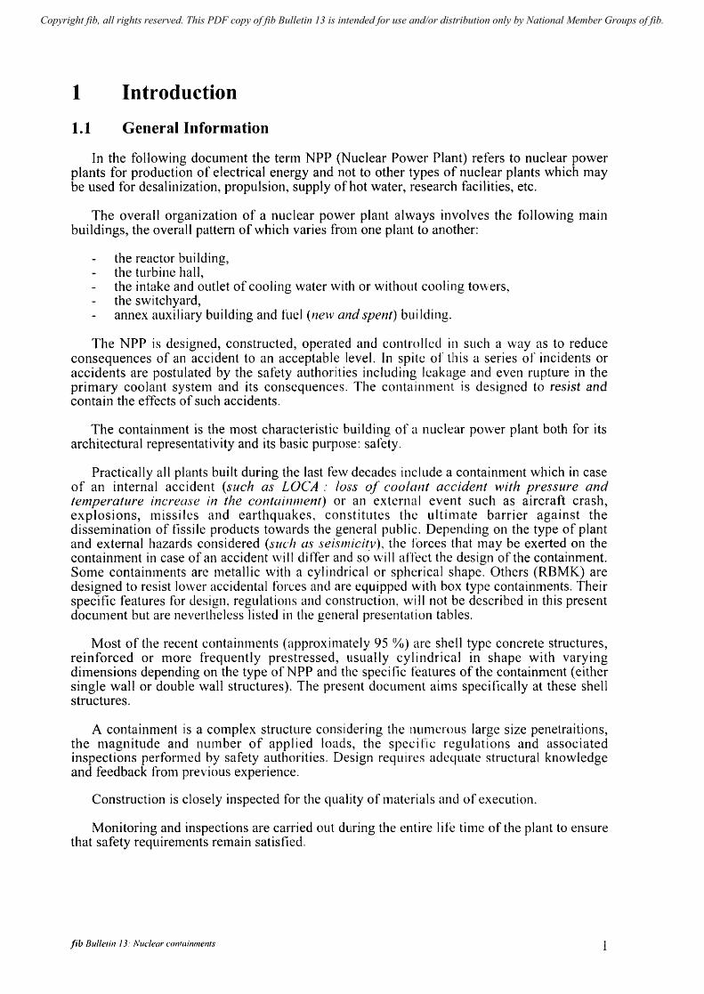
In the following document the term NPP (Nuclear Power Plant) refers to nuclear power plants for production of electrical energy and not to other types of nuclear plants which may be used for desalinization, propulsion, supply of hot water, research facilities, etc.
The overall organization of a nuclear power plant always involves the following main buildings, the overall pattern of which varies fro111 one plant to another:
the reactor building, the turbine hall, the intake and outlet of cooling water with or without cooling to\vers, the switchyard, annex auxiliary building and fuel (new and spent) building.
The NPP is designed, constructed, operated and controlled in stich a way as to reduce consequences of an accident to an acceptable level. In spite of this a series of incidents or accidents are postulated by the safety authorities including leakage and even rupture in the primary coolant system and its consequences. The containment is designed to resist and contain the effects of such accidents.
The containment is the most characteristic building of a nuclear power plant both for its architectural representativity and its basic purpose: sarety.
Practically all plants built during the last few decades include a containment which in case of an internal accident (such as LOCA .' loss of coo/ant accident with pressure and temperature increase in the containment) or an external event such as aircraft crash, ex p losi ons, miss i I es and earthquakes, consti tutes the u I ti mate barrier against the dissemination of fissile products towards the general public. Depending on the type of plant and external hazards considered (sllch as seismicity), the forces that Inay be exerted on the containment in case of an accident will differ and so \vill affect the design of the containment. Some containments are metallic \vith a cylindrical or spherical shape. Others (RBMK) are designed to resist lower accidental forces and are equipped with box type containments. Their specific features for design, regulations and construction, wi II not be described in this present docu111ent but are nevertheless listed in the general presentation tables.
Most of the recent containments (approxin1ately 95 0/0) are shell type concrete structures, reinforced or more frequently prestressed, usually cylindrical in shape with varying dimensions depending on the type ofNPP and the specific features of the containment (either single wall or double wall structures). The present document ailTIS speci fical1y at these shell structures.
A containment is a c01nplex structure considering the numerous large size penetraitions, the magnitude and number of applied loads, the speci fic regulations and associated inspections perforn1ed by safety authorities. Design requires adequate structural knowledge and feedback from previous experience.
Construction is closely inspected for the quality of materials and of execution.
Monitoring and inspections are carried out during the entire life time of the plant to ensure that safety requirements remain satistied.
fib Bulle/in 13: Nllclear l'Onfainments 1
Copyright fib, all rights reserved. This PDF copy of fib Bulletin 13 is intended for use and/or distribution only by National Member Groups of fib.
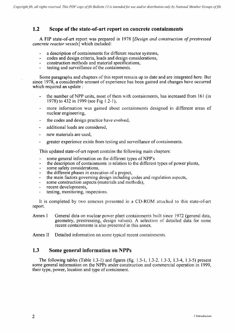
1.2 Scope of the state-of-art report on concrete containments
A FIP state-of-art report was prepared in 1978 [Design and construction of prestressed concrete reactor vessels] which included:
a description of containments for different reactor systems, codes and design criteria, loads and design considerations, construction methods and material specifications, testing and surveillance of the contaimnents.
Some paragraphs and chapters of this report renlain up to date and are integrated here. But since 1978, a considerable amount of experience has been gained and changes have occurred which required an update:
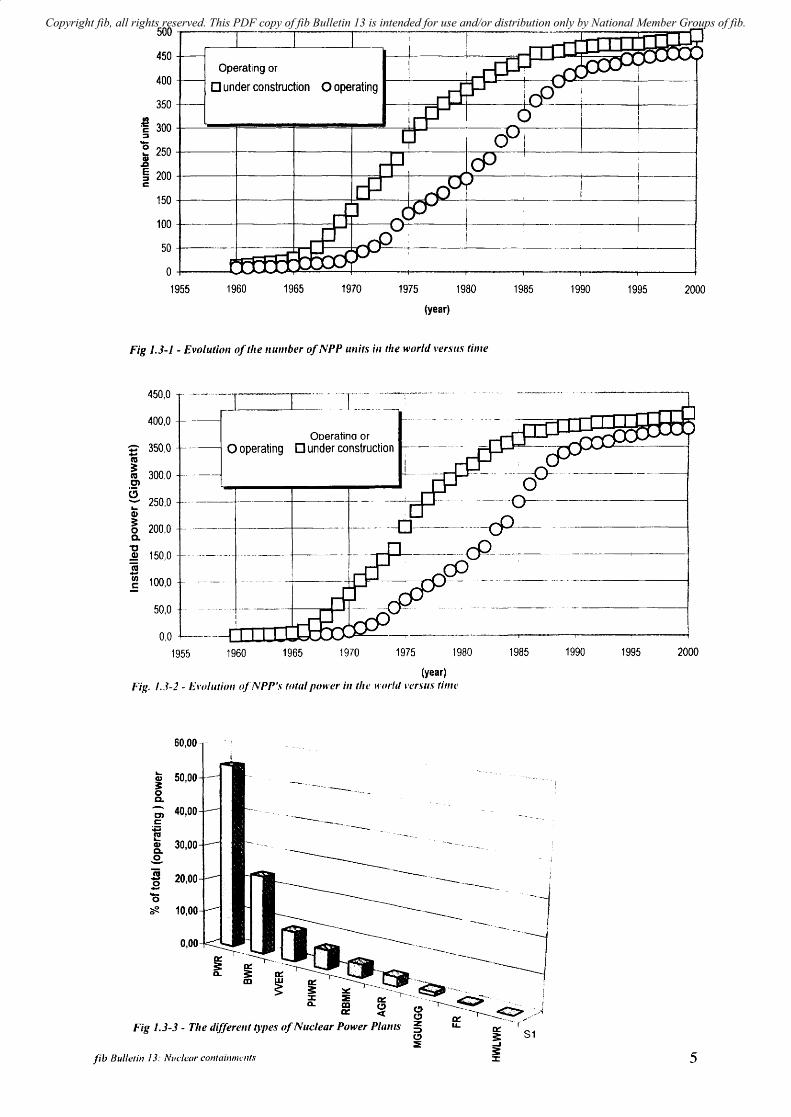
the number ofNPP units, lnost of them \\!ith contaimnents, has increased fronl 161 (in 1978) to 432 in 1999 (see Fig 1.2-1),
Inore infornlation was gained about containments designed in different areas of nuclear engineering,
the codes and design practice have evolved,
additional loads are considered,
new materials are used,
greater experience exists from testing and surveillance of containments.
This updated state-of-art report contains the following main chapters:
some general infonnation on the different types ofNPP's the description of containments in relation to the different types of power plants, some safety considerations, the different phases in execution of a project, the main factors governing design including codes and regulation aspects, some construction aspects (materials and methods), recent developlnents, testing, monitoring, inspections.
It is completed by two annexes presented in a CD-ROM attached to this state-of-art report.
Annex I General data on nuclear po\ver plant containments built since 1972 (general data, geometry, prestressing, design values). A selection of detailed data for some recent containments is also presented in this annex.
Annex II Detailed information on some typical recent containments.
1.3 Some general information on NPPs
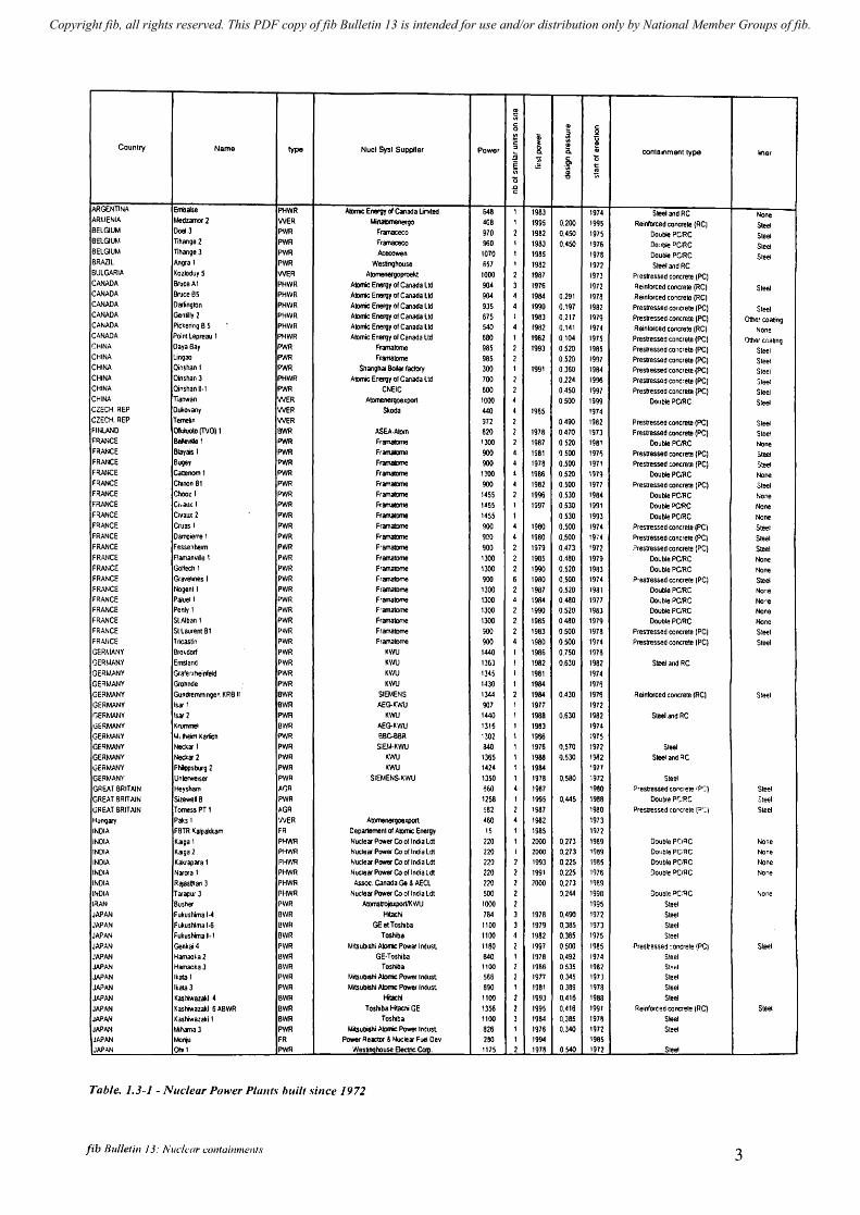
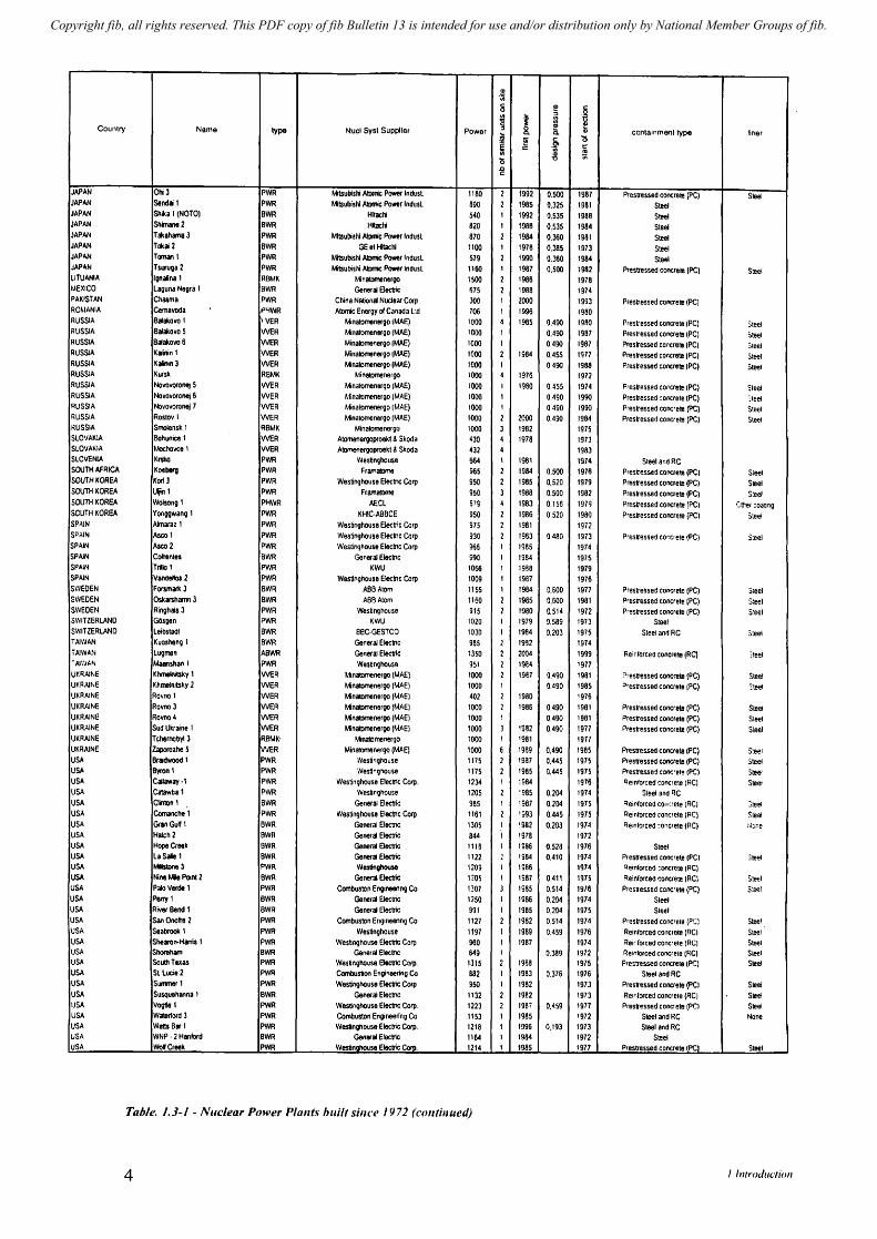
The following tables (Table 1.3-1) and figures (fig. 1.3-1, 1.3-2, 1.3-3, 1.3-4, 1.3-5) present SOlne general information on the NPPs under construction and conlmercial operation in 1999, their type, power, location and type of containment.
2 I Introduction
Copyright fib, all rights reserved. This PDF copy of fib Bulletin 13 is intended for use and/or distribution only by National Member Groups of fib.
~ c: QI
~ 0 :; .. III ~ -g § ~ [ Counlry Name type Nucl Sysl Supplier Power 8. OJ conlainmenl type liner ~ .. .6- 0
~ .= ~
!; 0
-;;;
.g
ARGENTINA Embalse PHWR AIImc Energy d Canada limited 646 1 1983 1974 Steel and RC None ARMENIA Me!Jzanor 2 WER MinaPnenerQO 408 1 1995 0.200 19'J5 Reinforced concrete IRC) SIee! BELGIUM DoeI3 PWR Framaceco 970 2 1982 0.450 1975 Double PCiRC SleeI BelGIUM Trhange 2 PWR Fr.rnaceco 960 1 1983 0.450 1976 Double PCIRC SleeI BELGIUM Trhange 3 PWR Acecowen 1070 1 1985 1978 Double PCiRC SleeI BRAZIL Angra 1 PWR Westinghouse 657 1 1982 1972 SIee! and RC BULGARIA KozJoduy 5 WER Atomenergoptoekt 1000 2 1987 1973 Prestressed concrete IPC) CANADA Bruce AI PHWR ~ic Energy of Canada Lid 904 3 1976 1912 Reinforced concrete (RC) SIee! CANADA Bruce 85 PHWR Atomic Enlll1n of Canada Lid 904 4 1984 0.291 1918 Reinforced cor.crete (RC) CANADA DiringlOn PHWR Atomic Energy of Canada Lid 935 4 1990 0.197 1982 Preslressed concrete (PC) SleeI CANADA Gen~11y 2 PHWR AIOmic Energy of Canada Lid 675 1 1983 0.217 1979 Prestressed concrete (PC) OtIler coaling CANADA PiCkering B 5 PHWR Atomic Energy of Canada Lid 540 4 1982 0.141 1974 Relnforced concrete (RC) None CANADA Point Lepreau 1 PHWR Atomic Energy of Canada ltd 680 1 1982 0.104 1975 Prestressed concrete (PC) Other ccabng CHINA Daya Bay PWR Framalome 985 2 1993 0.520 1985 Preslressed concrete (PC) Steel CHINA Lingao PWR Framatome 985 2 0.520 1997 Prestressed concrete (PC) SleeI CHINA Qinshan 1 PWR Shanghai Boiler factory 300 1 1991 0.360 1984 Prestressed concrete (PC) Sleel CHINA Oinshan 3 PHWR Ailmic Energy of Canada lid 700 2 0.224 1996 Preslressed concrete (PC) SleeI CHINA Qinshan 11·1 PWR CNEIC 600 2 0.450 1997 Preslressed concrete (PC) Slee! CHINA lianwan WER AtomellergoexDOlt 1000 4 0.500 1999 Double PClRC Steel CZECH REP Duko_any WER Skoda 440 4 1985 1974 CZECH. REP Temelin WER 972 2 0.490 1982 Prestressed concnete (PC) SleeI FINLAND (»iuolD (TVO) I BWR ASEA·AIom 820 2 1978 0.470 1973 Preslressed concnete (PC) Stei!l FIWlCE Bei'eWIe 1 PWR Ffanlaltime 1300 2 1987 0520 1981 Double PClRC None Fi~ANCE Blayais 1 PWR Fr~ 900 4 1981 0.500 197~ Prestressed concrete (PC) Steel FRANCE Sugey PWR FnwnaIcme 900 4 1978 0.500 1971 Prestressed :oncrete (PC) Steel FRANCE Cattenom1 PWR Framalllme 1300 4 1966 0.520 1979 DoublePC.~C None FRANCE Chlnon 81 PWR Framalllme 900 4 1982 0.500 1977 Presl1essed concre:e (PC) 3teeJ FRANCE Choozl PWR Framalllme 1455 2 1996 0.530 1984 Double PC;RC Nooe FRANCE Ci.aux 1 PWR Framalllme 1455 I 1997 0.530 1991 Double PCIRC None FRANCE Civaux 2 PWR FramatDme 1455 I 0.530 1993 Double PCIRC None FR,\lI/CE Cruas 1 PWR Framatome 900 .. 1980 0.500 1974 Prestressed concrete (PC) Steel FRANCE Damcierre 1 PWR Framatome 900 4 1980 0.500 19,4 Prestressed concrete (PC) Steel FRANCE Fessenhelm PWR Framatome 900 2 1979 0.473 '972 ?restressed concrele {PC) Steel FRNlCE Flaman1l111e I PWR Framatome 1300 2 1985 OA80 1979 Double PORC None FRANCE Go~ech 1 PWR F'amatome 1300 2 1990 0.520 19~3 DoublePClRC None FRANCE Gca.el'nes 1 PWR Framatome 900 6 1980 0.500 1974 Prestressed concrele (PC) SIee! FRANCE l-Iogenll PWR FramalOme 1300 2 1987 0.520 1981 OoublePCIRC None FRANCE PalueJ 1 PWR Framatome 1300 4 1984 0.480 1971 Double PORC No~e
FRANCE Penly 1 PWR Framatome 1300 2 1990 0.520 19a3 Double PCIRC None FRANCE SlAlban 1 PWR Framatome 1300 2 1985 0.480 1979 Double pClRe None FRANCE Sl Laurent 81 PWR Framatome 900 2 1983 O.SOO 1978 Prestressed concrele (PC) Steel FRANCE Tricastin PWR Frama1Dme 900 4 1980 0,500 1974 Prestressed concrete (PC) Sleel GERMANY Brol.dorl PWR KWU 1~ I 1986 0,750 1976 GER~V.NY Emsland PWR KWU 1363 1 1982 0,630 1982 SIee! and RC GERMANY Grafer.rheinfeld PWR KI'N 1345 I 1981 1974 GE'lMANY Grohnde PWR KWU 1430 1 1984 1976 GERMANY Gundremmlngen KRB II BWR SIEMENS 1344 2 1984 0.430 19~ Relnforced concrele IRC) Sleel GERt.WlY Isa- 1 BWR AEG-K'I.'U 907 1 1977 1972 GER~WlY lsar 2 PWR KWU 1~ 1 1988 0.630 1982 Steel and RC GERt.WlY KrurrvneI BWR AEG-K'v'N 1316 1 1983 1974 GERMANY MLIII6'nKat1icn PYlR BBC-8BR '302 1 1966 :975 GER/.WIY Ned<iW 1 PWR SIEJ.4-KYN a40 1 1976 0.570 1972 Steel GERt,\,\lI/Y Necl<iW2 PWR 1('''''.1 1365 1 1988 0.530 1982 Steel and RC GE;;~WIY Fhilppsbu'g 2 PWR K't'.'IJ 1424 1 1984 1971 GERMANY Unterwelser PWR SIEJAEN5-KWU 1350 1 1978 0.580 :972 SIe~
GREAT BRITAIN Heysham AGR 660 4 1987 1980 Prestressed coooere IPS) Steel GREAT BRITAIN SizeweQ 8 PWR 1258 1 1995 0.445 1988 DoublePG:RC Steel GREAT SRIT AlN Torness PT I AGR ~82 2 1987 1980 Prestressed Contrete (P':,) Steel HUl1()iI/)' Paks I WER AlDmenergoexpm 460 4 1982 1973 INDIA FBTR I(alpakkam FR Deoal1emenl of Ailn1c Energy 15 1 1985 1972 INDIA KiJga 1 PHWR Nuclear Power Co of India Ldl 220 1 2000 0.273 1989 Double PCIRC None INDIA Kilga 2 PHWR Nuclear PDWer Co of India Ldt 220 I 2000 0,273 1989 Double PCIRC None INDIA Kakrapara 1 PHWR Nuclear Power Co of India Ldt 220 2 1993 0.225 1985 D?uble PCIRC None INDIA NiWora 1 PHWR Nuclear Power Co of India Ldl 220 2 1991 0.225 1976 Double PCIRC None INDIA Rajasll1an 3 PHWR Assoc. Canada Ge & AECL 220 2 2000 0.273 1989 INDtA Tarapur J PHWR Nuclear PDWer Co of India Ldt 500 2 0.244 1998 Doubl .. pciRe ,,"one IRAN Busher PWR AIDmSIrOjeJj)ort/KWU 1000 2 1995 Steel JAPAN Fukushima 1-'1 BWR Hitachi 784 3 1978 0,490 1972 Steel JAPAN Fukushima 1·6 BWR GEetToshiba 1100 J 1979 0,385 1973 Steel JAP,\lI/ Fukushima 11·1 BWR Toshiba 1100 4 1982 0.385 1975 Steel JAPAN Genkli 4 PWR Mltsu~shi Abric Power Indust 1180 2 1997 0500 1985 Prestressed :oncrete (PC) Steel JAPAN H;wnaoka 2 BWR GE·Toshiba 840 f 1978 0.492 1974 Steel JAPAN Hamaok3 J BWR Toshiba 1100 2 1986 0.535 1982 Sleel JAPAN Ikalal PWR Mrtsubl$hi Atonic Power Indust 566 2 19n 0345 1973 Steel JAPAN Ikala 3 PWR Mrtsubislli AlDrric: Power IMust 890 1 1981 0.389 1978 Sleel JAPAN KaslWiazakl ( BWR IitacI1 1100 2 1993 0.416 1988 Steel JAPAN KaslWi3Zaij 6 ABWR BWR T os/uba Hitachi GE 1356 2 1995 0.416 1991 ReInforced concrele IRC) SIee! JAPAN KaslWi313kl1 BWR Toshiba 1100 3 1984 0.385 197& Steel JAP,\lI/ '.ihana J PWR Mitsubishi AlDrric: Power I".just 826 1 1976 0.340 1972 SleeI JAPAN Monju FR Power Reactllt & Nuclear Fuel Oev 260 1 1994 1965 JAP.\.N 0Ii 1 PWR Wennqhouse Electric Corp. 1175 2 1978 0.540 1972 Sleet
Table. 1.3-1 - Nue/ear Power PhillIs buill since 1972
fib Bulletin J 3: iVuc!i.'l7r containments 3
Copyright fib, all rights reserved. This PDF copy of fib Bulletin 13 is intended for use and/or distribution only by National Member Groups of fib.
(I)
.~
8 ~ .~ .~ I i ~
Country Name type Nucl Syst Supplier Power iii ccntainment type liner i Q.
~ c '5
~ .~ li (I) 1;; (5 '0
~
JAPAN 0Ii3 PWR Mlsublsl1i Atomic Power Indusl 1180 2 1992 0.500 1987 Prestressed concrele (PC) Steel JAPAN Sendaj I PWR MitsubisN Atomic Power Indusl 690 2 1985 0.325 1981 Steel JAPAN Shika I (NOTO) BWR Hijachl 541J I 1992 0.535 1988 Steel JAPAN Shimane 2 BWR Hllachl 820 I 1988 0.535 1984 Steel JAPAN Takahama 3 PWR Mi1sublslii AIDmIc Power Indusl 870 2 1984 0.360 1981 Steel JAPAN Tokai2 BWR GEetHtachi 1100 1 1978 0.385 1973 Steel JAPAN Tom;wi t PWR MilsubisN AIIln1c Power lodusL 579 2 1990 0.360 19M S'.eeI JAPAN TSWIIga 2 PWR Mitsubishi AIIln1c Power Indusl 1160 1 1987 0.500 1982 Prestressed coocrele (PC) Steel LITUANA Ignaina I RBMK ~tinatomellergo 1500 2 1986 1978 MEXICO Laguna Negra 1 BWR General8ec1Jic 675 2 1988 1974 PAKISTAN Chasma PWR Cliina National Nuclear COIJI. 300 I 2000 1993 Preslressed concrete (PC) ROMANIA Cema'iOda I"YWR A10mic Energy ofCanilda L:d 706 1 1996 1980 RUSSIA BaiakollO 1 'VER Minatomenergo (MAE) 1000 4 1985 0.490 1980 Pres~essed concrete (PC) Steel RUSSIA BaiakollO 5 WER Minatornenergo (MAE) 1000 I 0.490 1987 Pres~essed concrete (PC) ~teel RUSSIA BalakollO 6 WER Minalomenergo (MAE) 1000 I 0490 1987 Preslressed concrete (PC) Steel RUSSIA Kajinin 1 WER Minatomenergo (MAE) 1000 2 1984 0.455 1917 Preslressed concrete (PC) ~eel RUSSIA KaIilln3 WER l.4inaklmenergo (MAE) WOO 1 0490 1988 Pnestressed concrete (PC) Steel RUSSIA Kursk RBMK MinatomenerQO 1000 4 1976 1972 RUSSIA NollOvoronllf 5 WER Mina1omenergo IMAE) 1000 I 1980 0.455 1974 Preslressed concrete (PC) Sleet RUSSIA Nol'Ovoronej 6 WER Minatomenergo IMAE) 1000 1 0.490 1990 Presb'essed ~oncrete (PC) ,Ieel RUSSIA Novovoronej 7 WER Mina1omener90 I MAE) 1000 I 0.490 1990 Preslressed concrell! (PC) S\eel RUSSIA ROSIOY I WER Minatomenergo IMAE) 1000 2 2000 0,490 1984 Preslressed concrele (PC) Steel RUSSIA Srnotensk 1 RBMK Mlnalornenergo 1000 3 1982 1975 SLOVAKIA Bohunice I WER Atomenergoproeld & Skoda 430 4 1978 1973 SLOVAKIA Mochovce I WER A1omenergoproekl & Skoda 432 4 1983 SLOVENIA Krsko PWR Westinghouse 664 I 1981 1974 Steela".dRC SOUTH AFRICA Koeberg PWR FramalOmll 965 2 1984 0.500 1978 Prestressed concrete (PC) Sleet SOUTH KOREA KoriJ PWR Westinghouse EJectroc CoIJl 950 2 1985 0.520 1979 Preslressed concrete (PC) Sleel SQUTHKOREA lJljinl PWR Framatome 950 3 1988 0.500 1982 Presb'essed concrete (PC) S:eel SOUTH KOREA Wolsong 1 PHWR AECL 579 4 1983 0.156 1m Prestressed concrete (PC) ':1I>er :oaong SOUTH KOREA 'fonggwanq 1 PWR KHIC·ABBCE 950 2 1986 0,520 1980 Presb'essed concrete (PC) Steel SPAJN Almaraz 1 PWR Westinghouse Elei:tric COIJl 975 2 1981 1972 SPAIN Asco I PWR Westinghouse Electrlc COIJl 930 2 1983 O.4ilO 1973 Prestressed CO"."ete (PC) S:eel SPAIN Asco 2 PWR Westinghouse Elei:1I'1c COIJl g66 I 1985 1974 SPAIN CofrenleS BWR General Eie(tlc ;90 1 1984 1975 SPAIN Trillo 1 PVIR KWU 1056 I 1988 1979 SPAIN Vandeb2 PYlA Westinghouse E1ecUic CofJ) 1009 I 1987 1976 SWEDEN Forsmarll 3 BWR ABBAlom 1155 I 1984 0.600 1977 Prestressed concrete (PC) Sleel SWEDEN Oskarsh..nn 3 BWR ABBAlom 1160 2 1985 0.600 1981 Prestressed concrete (PC) S:eel SWEDEN Ringhals 3 PWR Westinghouse 915 2 1980 0.514 1972 PrestreSSed concrete (PC) S:eel SWITZERLAND GOsgen PWR KWU 1020 I 1979 0.589 1973 Steel SWITZERLAND Leibstadl BWR BBC·GESTCO 1030 1 1984 0.203 1975 Sleel and RC Steel TAIWAN Kuosheng 1 BWR General Eleclllc 985 2 1982 1974 TAlW~," Lugmen ABWR General Electic 1350 2 2004 1999 Reinforced concrete (RC) :teet ·AJ'''I~'' Malshao I PWR Westngho~se 951 2 19a4 1977 Ur.RAI~,E Khmeloitsky 1 WER Minatomenelgo (MAE) 1000 2 1987 Q.490 1981 ?restressed toncre1e (PC) Steel Ur.RAI~.E Khmelrutsky 2 WER MinatomenerQO (MAE) 1000 1 0.490 1985 Preslressed concrete (PC) "tee! UKRAINE Ro,no I WER MinatomenerQO (MAE) 402 2 1980 '976 UKRAINE Rovno J WER MinatomenerQO (MAE) lOCO 2 1986 0.490 1981 Preslressed concrete (PC) Steel UKRAINE Rovno 4 WER MinatomenerQO (MAE) 1000 1 0,490 1981 Prestressed concrete (PC) Sleel UKRAINE Sud Ukraioe I WER MinatomellerQO (MAE) 1000 J 1982 0.490 1917 Preslressed concrete (PC) Steel UKRAINE Tchemobyt 3 RBMK' Minatornenergo 1000 , 1981 1977 UKRAINE Zaporozhe 5 liVER Minatomenelgo (MAE) 1000 6 ~989 0,490 1985 Preslresse(J concrete (PC) Steel USA Brlldwood 1 PWR 'Nesting/louse 1175 2 1987 0.445 197~ Preslressed concrete (PC) Steel USA Byron I PWR ',ves1lngnouse 1175 2 1985 0.445 197~ Prestresse1 cooc'efe (PC) Steel USA CcMl2way·l PWR Westinghouse Electric COIJ!. 1234 I ~ 984 1976 qellt/orceli cOlICre~ (RCI SteeJ USA Catawba I PWR Westi"ghouse 1205 2 '985 0.204 1974 Sleet and RC USA Clin10n 1 BWR General EIec1Jic 985 1 '987 0.204 1975 qeimorced con~rete IRC! 31eel USA Comanche 1 PWR Westinghouse Electric COIJ! 1161 2 '993 0,445 1975 Reinforced contrele (PC) Sleel USA GranGu~ 1 BWR General Elecmc 1305 I '982 0.203 1974 qelnforced :oncrele IRC) II one USA Hatch 2 BWR General EIec1Jic 844 1 1978 1972 USA Hope Creek BWR General8ec1Jic 1118 I 1986 0.528 1976 Steel USA La Sale 1 BWR General8ectJic 1122 2 1964 0.410 1974 Preslressed concrete (PC) Steet USA MiIsIDne 3 PWR Wes1Ingho\lse 1209 I 1;86 1974 qeinforced :ooclete IRC) USA Nine !Me PoInt 2 BWR GeneralEltt1Jic 1,OS \ IS81 0,411 1915 qeinforced concrete (RC) S:eel USA Palo lIerde I PWR Combuston Engi.-ifl9 Co 1307 J 1585 0.514 1916 Pr~5~essed concrete (PC) S:eel USA Perry I BWR GelleraiElectric 1250 I 1986 0.204 1974 Sleet USA River Bend 1 BWR General ElectJic 991 I 1985 0.204 1975 Steel USA San Onofre 2 PWR Combuslon Engineering Co 1127 2 1982 0,514 1974 Prestressed concrele (P(;) Steel USA Seabrook 1 PYlA Westinghouse 1197 1 1989 0.459 1976 Reinlorced concrell! (RCI Steel USA Sheil'OfIoHarris 1 PWR Westinghouse Electric Corp 960 I 1987 1974 Remforced concrele (Rct Steel USA Shoraham BWR General Electnc 849 I 0.389 1972 Reinforced cOnGrete (RC) Steel USA South Texas PWR Westinghouse 8ectric CeIJl 1315 2 19Sa 1975 Prestressed concrete (PCI Steel USA Sl Lucie 2 PWR Combustion Engineering Co 882 I 1983 0.376 1976 Sleeland RC USA SLI'ImIII PWR Westinghouse Electric Corp 950 1 1982 1973 Preslressed concrete (PC) Steel USA Susquehanna 1 BWR General E1ecUic 1132 2 1982 1973 Reinrorced concrele (RC) Steel USA Vogde 1 PWR Westinghouse Electric CoIJl. 1223 2 1987 0.459 1977 Preslressed concrete (PCI Steel USA Wa1et1ord 3 PWR Combuston Engineering Co 1153 I 1985 1972 Steel and RC None USA Watts Bar 1 PWR Westinghouse EIei:1ric CoIJl. 1218 I 1996 0.193 1973 Steel and RC USA WNP·2H8I1ford BWR General ElecUic 1164 I 1984 1972 Steel USA WoffCreek PWR Westinahouse Electric Cell). 1214 1 1985 1977 Prestressed concrete (PCI Steel
Table. 1.3-1 - Nue/ear POHler Plants built since /972 (Colltillued)
4 1 Introductio/l
Copyright fib, all rights reserved. This PDF copy of fib Bulletin 13 is intended for use and/or distribution only by National Member Groups of fib.500
450 Operating or
400 o under construction o operating 350
:@ 300 c
::J -0 250 ... .! E 200 ::J c
150
100
50
0 1955 1960 1965 1970 1975 1980
(year)
Fig 1.3-1 - Evolution of tire "umber of NPP ullits ill tile world verms time
450,0 . __ .. _]
400,0 -r~ operating - 350,0 --cu ~ 300,0 cu C)
__ ~_ .. ". '.-r~._~ ... ___ .. __ ._U .....
Ooeratina or o under construction
~ 250,0 .--... CD ~ 200,0 0 Q. "C
150,0 .!! (ij -U) 100,0 E
50,0
0,0 1955 1960 1965 1970 1975 1980
(year) Fig. 1.3-2 - /;'\'0/111;011 ofNPP's tot{ll power ill tlte world verslIs time
60,00
~ 50,00
c-O) 40,00 c .. ~ CD 0. ~
30,00
20,00
'--. -._----
.---------------. "'--
1985
1985
I -------~ - -.-J 10,00 -. I -----. 0,00 f~-",C!cie. . -------=~
m ~7-f!f!~~<:>- .... ~ ~ g ;--r-.~ .. >~
Fig 1.3-3 - Tire different types of Nuclear Power Pltmls ~ u.. £r ---. r .... ~ ~ 81 ~ ~
::I: fib BulleTin 13: Nuclear containmcnts
1990 1995 2000
. " .... _-_._----,
1990 1995 2000
5

Copyright fib, all rights reserved. This PD
F copy of fib Bulletin 13 is intended for use and/or distribution only by National M
ember G
roups of fib.
0\ % of total power
..... ..... ...... % of total power 0 I\J ~ en (XI 0 I\) ~ en (XI
"'l 0 rn I\) N Co> "!l ~' 0 0 c.n 0
~' - ARGENTINA :-- KWU t.... ~
~ ARMENIA ~
~ BelGIUM
fi1 m g El m 0 El :; Atomic Energy of
"'I BRAZL to ~ ~ ::u ~ 3: ." :J: ~ Canada Ltd \")
== ::I: to (i) G') ::u
== S ~ :: BULGARIA ::u m
== 3: ::u c: r- ::::
~ ::u ::u A z :E ~ Framatome ~
CANADA (i) ;0 . ~
~ G') ~
CHINA ~ ~
S "'I ASEA·Atom
~ FINLAND .~
::' FINLAND So S ~
FRANCE S; ABBAtom ~ GERMANY ~ l:l.. "'I
~ GREAT BRITAJH ~ :: Hitachi \") GREAT BRITAJH '"
I~ fi1 m bJ El ;;; -§ I:l
~ OJ ~ -0 ::u "'I HOLLAND "ti ~ Mitsubishi Atomic :E :::I: OJ '"0 ::u ::u m :E 3: ~ HUNGARY ~ ::u
~ Power Indust. ::u ~ ~ INDIA
~
s· ~ ~
IRAN ¢ Toshiba I:l ~ ~ JAPAN ~ ::;- '" \")
KAZAKHSTAN ~ ~ GE etToshiba :: ~ :: UTUANIA ~ .s ~
MEXICO
:: Babcock & Wilcox ~
~ RUSSIA jJnn[TI Combustion !';)
~ Engineering Co ':l' SLOVAKIA ~
SLOVENIA L General Electric SOUTH KOREA
SPAIN J;;:! Westinghouse
SPAIN
SWEDEN
~ SWITZERLAND r Minatomenergo
0 SWITZERlAND
S. 3. TAIWAN t~ Atomenergoexport c :: UKRAINE
USA

Copyright fib, all rights reserved. This PDF copy of fib Bulletin 13 is intended for use and/or distribution only by National Member Groups of fib.
2 Containments for different reactor types
2.1 General
The review only addresses reactors which are in commercial operation or under constructi on.
It should be noted that no containments are completely made of prestressed concrete. The basemat is always constructed of reinforced concrete or slightly prestressed concrete.
2.2 The different types of recent Nuclear Power Plants (NPP)
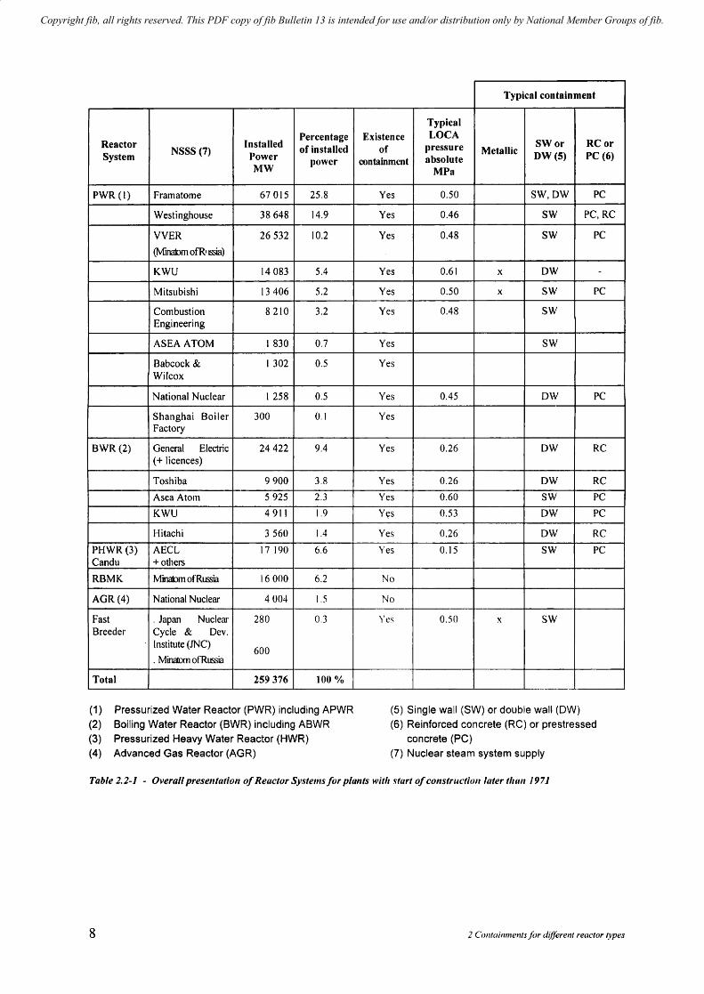
Table 2.2-1 hereafter lists the main types of recent NPP and total installed power. It also presents some preliminary information concerning the corresponding containments which varies from one reactor type to the other.
Table 2.2-1 is limited to Nuclear Power Plants in eotnlnercial operation in 1999 and for which construction started after 1971. These are referred to as recent N PPs and are assumed to be more representative of the present state of the art.
Two observations can immediately be made:
the relative importance of the PWR type of reactor \vhich represents 76 % of the total power installed since 1978 (including VVER),
the fact that all recent NPPs include a metallic, reinforced concrete or prestressed concrete containment with the exception of RBMK units and AGRs. The later are designed with a prestressed concrete pressure vessel (PCPV).
It can also be noted that the total power corresponding to the recent NPP units represents approximately 70 % of the total existing NPP power \vhieh is at present 370.000 MW.
This shows the considerable development of nuclear power supply over the last two decades.
fib Bulletin 13: Nuclear containment.\ 7
Copyright fib, all rights reserved. This PDF copy of fib Bulletin 13 is intended for use and/or distribution only by National Member Groups of fib.
Percentage Reactor Installed of installed NSSS (7) Power System power
MW
PWR (I) Framatome 67015 25.8
Westinghouse 38648 14.9
VVER 26532 10.2
(Minalom ofR.~)
KWU 14083 5.4
Mitsubishi 13406 5.2
Combustion 8210 3.2 Engineering
ASEA ATOM ) 830 0.7
Babcock & ) 302 0.5 Wilcox
National Nuclear ) 258 0.5
Shanghai Boiler 300 0.1 Factory
BWR(2) General Electric 24422 9.4 (+ licences)
Toshiba 9900 3.8
Asea Atom 5925 2.3
KWU 4911 1.9
Hitachi 3560 1.4
PHWR (3) AECL 17 190 6.6 Candu + others
RBMK Minalom of Russia 16000 6.2
AGR (4) National Nuclear 4004 1.5
Fast . Japan Nuclear 280 OJ Breeder Cycle & Oev.
Institute (JNC) 600
. Minatom of Russia
Total 259376 100 %
(1) Pressurized Water Reactor (PWR) including APWR (2) Boiling Water Reactor (BWR) including ABWR (3) Pressurized Heavy Water Reactor (HWR) (4) Advanced Gas Reactor (AGR)
Typical containment
Typical Existence LOCA
of pressure Metallic SWor RCor DW(5) PC (6) containment absolute
MPa
Yes 0.50 SW,OW PC
Yes 0.46 SW PC,RC
Yes 0.48 SW PC
Yes 0.61 x OW -
Yes 0.50 x SW PC
Yes 0.48 SW
Yes SW
Yes
Yes 0.45 OW PC
Yes
Yes 0.26 OW RC
Yes 0.26 OW RC
Yes 0.60 SW PC
Y~s 0.53 OW PC
Yes 0.26 OW RC
Yes 0.15 SW PC
No
No
Yes 0.50 x SW
M ___ ~ •
(5) Single wall (SW) or double wall (OW) (6) Reinforced concrete (RC) or prestressed
concrete (PC) (7) Nuclear steam system supply
Table 2.2-1 - Overall presentation of Reactor SJ'stems for plants witlt ... tart of cOllstructioll later tltall /97 J
8 2 CrJlltail1lllents Ii)r d!{ferent reactor types
Copyright fib, all rights reserved. This PDF copy of fib Bulletin 13 is intended for use and/or distribution only by National Member Groups of fib.
2.3 Preliminary presentation of containments associated with the different reactor types
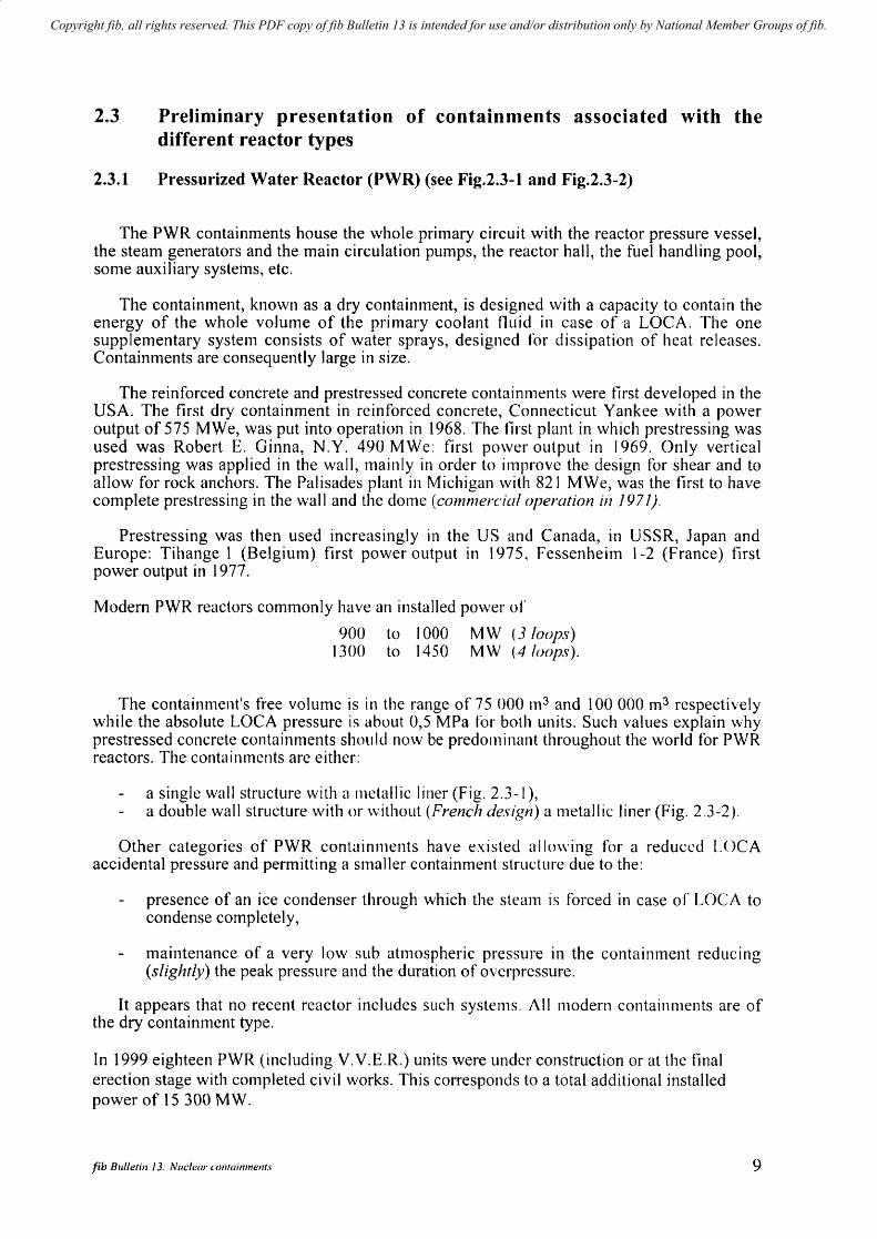
2.3.1 Pressurized Water Reactor (PWR) (see Fig.2.3-1 and Fig.2.3-2)
The PWR containments house the whole primary circuit with the reactor pressure vessel, the steam generators and the main circulation pumps, the reactor hall, the fuel handling pool, some auxiliary systems, etc.
The containment, known as a dry contaimTIent, is designed with a capacity to contain the energy of the whole volume of the primary coolant fluid in case of a LOCA. The one supplementary system consists of water sprays, designed for dissipation of heat releases. Containments are consequently large in size.
The reinforced concrete and prestressed concrete containments \vere first developed in the USA. The first dry containment in reinforced concrete, Connecticut Yankee with a power output of 575 MWe, was put into operation in 1968. The first plant in which prestressing was used was Robert E. Ginna, N.Y. 490 MWe: first power output in 1969. Only vertical prestressing was applied in the wall, mainly in order to improve the design for shear and to allow for rock anchors. The Palisades plant in Michigan with 821 MWe, was the first to have complete prestressing in the \vall and the dome (conunerch!l operation in 1971).
Prestressing was then used increasingly in the US and Canada, in USSR, Japan and Europe: Tihange 1 (Belgium) first power output in 1975. FessenheitTI 1-2 (France) first power output in 1977.
Modem PWR reactors commonly have an installed power of
900 to 1000 MW (3 loops) 1300 to 1450 MW (4 loops).
The containment's free volume is in the range of 75 000 m3 and 100 000 m3 respectively while the absolute LOCA pressure is abuut 0,5 MPa for both units. Such values explain why prestressed concrete containments should now be predominant throughout the vvorld for PWR reactors. The containments are either:
a single wall structure with a metallic liner (Fig. 2.3-1), a double wall structure with or \vithout (French design) a metallic liner (Fig. 2.3-2).
Other categories of PWR containments have existed allowing for a reduced LOCA accidental pressure and permitting a smaller containment structure due to the:
presence of an ice condenser through which the steam is forced in case of LOCA to condense completely,
maintenance of a very low sub atmospheric pressure in the containment reducing (slightly) the peak pressure and the duration of overpressure.
It appears that no recent reactor includes such systems. All modern containments are of the dry containment type.
In 1999 eighteen PWR (including V.V.E.R.) units were under construction or at the final erection stage with completed civil works. This corresponds to a total additional installed power of 15 300MW.
fib Bulletin J 3: Nue/ear containments 9
Copyright fib, all rights reserved. This PDF copy of fib Bulletin 13 is intended for use and/or distribution only by National Member Groups of fib.
0,80
090
± 0,00
-3,50
37,00 m 1. D.
38,80 m O. D.
Fig. 2.3-1 - Typical single-wall PWR COlltaillment
10 2 C ontainmellfsjor different reac:tor f)-pes

Copyright fib, all rights reserved. This PDF copy of fib Bulletin 13 is intended for use and/or distribution only by National Member Groups of fib.
Fig. 2.3-2 - Typical double-wall pn'R contaimnellt
fib Bulletin 13: lVl/de",. COI1(linmCI/!.I· 11

Copyright fib, all rights reserved. This PDF copy of fib Bulletin 13 is intended for use and/or distribution only by National Member Groups of fib.
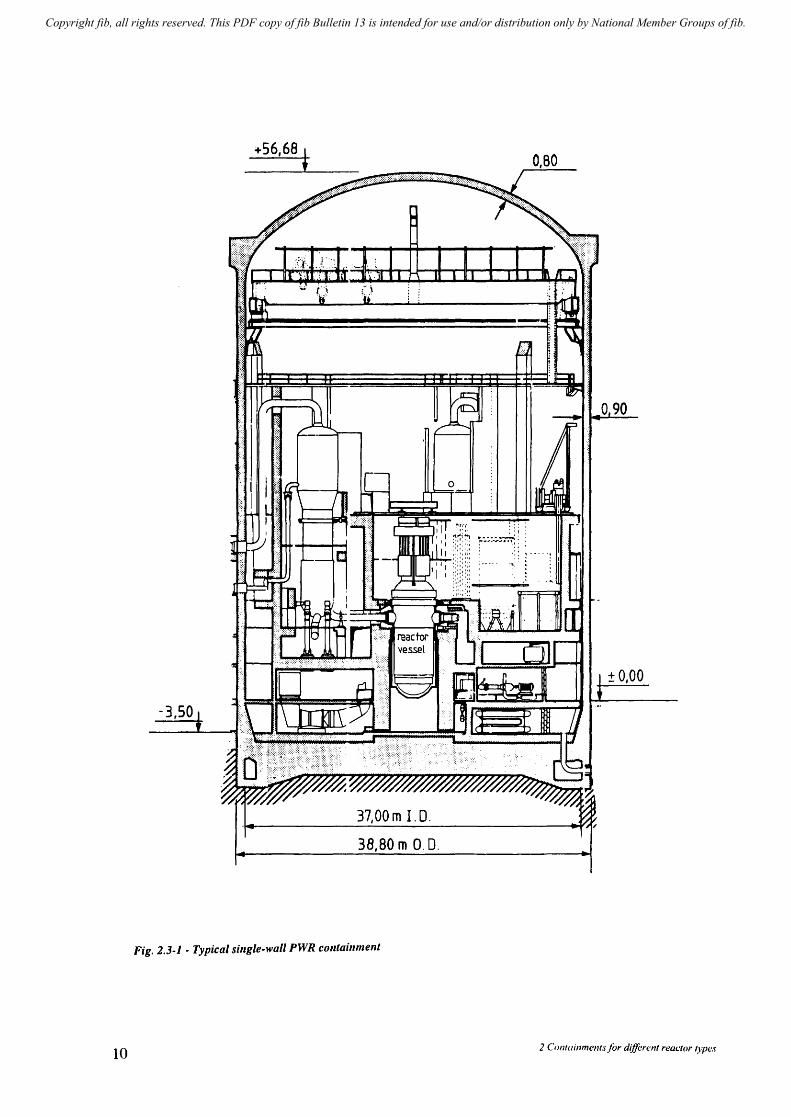
2.3.2 Boiling water reactors (BWR)
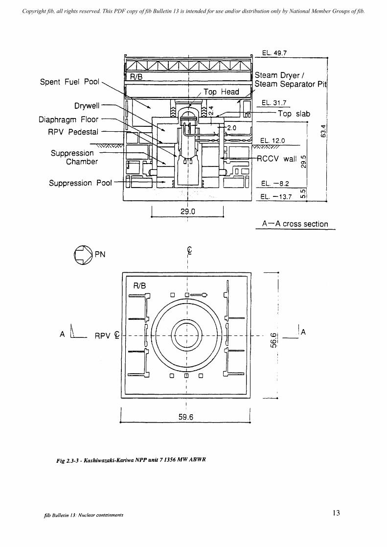
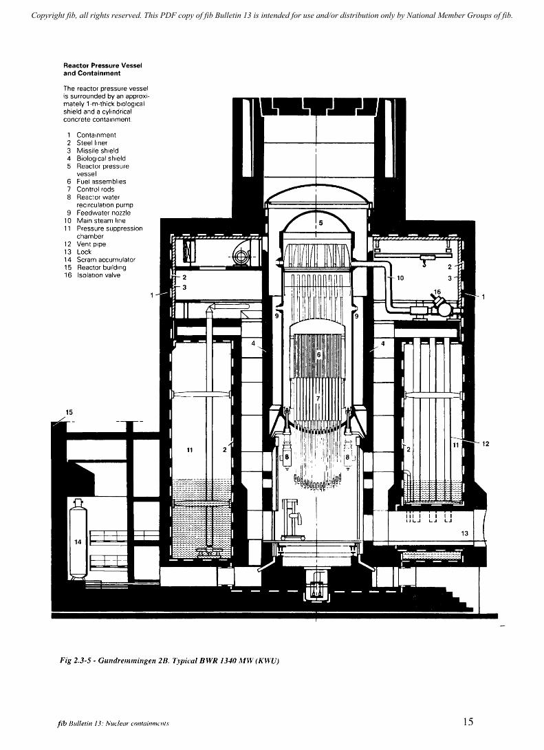
Most of the recent BWRs in operation are in the US, in Japan (General Electric and licensees) (see Fig. 2.3-3), in Sweden (Asea-Atom) (Fig. 2.3-4) or in Germany (KWU) (Fig. 2.3-5).
Boiling water reactors are all designed with a pressure suppression system (PS). The containment is divided into two main compartments, dry-well and wet-well. After a LOCA, the air and steam in the dry-well are forced through a number of down comers to a pool in the wet-well, where the steam condenses. Water spray systems are also provided. By this arrangement the containment can be kept quite small, about 116 of a dry containment for a LOCA accident in the region of 0,60 MPa absolute pressure. The auxiliary systems for the reactor are in most cases housed in a building which surrounds the containment and which is kept under slight sub-atmospheric pressure, thereby serving as a secondary containment.
In Scandinavia, two units of the Asea-Atom BWR design are in operation in Sweden, and two in Finland. They all have prestressed concrete containments, although the enclosure over the reactor vessel is a steel dome. The containment design is shown in Figure 2.3-4 (Oskarshamn 3). The basemat and the roof, which are cast integrally with the fuel handling pools, are only partly prestressed.
In Germany, the KWU reactor of the BWR type (AEG) had initially been designed with a spherical steel containment. KWU has since introduced a new design (Fig. 5) with a cylindrical containment in prestressed concrete, which has been built in Gundremmingen for a twin 1244 MWe plant.
Advanced BWR (ABWR) have be~ developed by GE and its Japanese licencees, Toshiba and Hitachi, and two ABWR unit~~ave been brought into operation in Japan in 1996 and 1997.
One of the unique features of ABWR is the use of a Reinforced Concrete Containment Vessel (RCCV) integrated with the reactor building, thereby enhancing the plant economy due to the decrease in plant size and increase of the seismic resistance capability due to lowering the centre of gravity.
Presently another two ABWR units are under construction in Lungmen, Taiwan.
12 2 Containmcnts Iii,. different reactor (}pes
Copyright fib, all rights reserved. This PDF copy of fib Bulletin 13 is intended for use and/or distribution only by National Member Groups of fib.
EL.49.7
Spent r---~----~------JI Steam Dryer / b------+------~ Steam Separator Pit
Drywell
Diaphragm Floor
R PV Pedestal ---t;=. .• ~-"';:o.,---l
Suppression Chamber
Su ppression Pool --I-+-I-I----I-t:..-..a.-=+=::::...b._-...J
A L RPV ~
RIB
i 29.0
~ I
] 0 ~=
---~ --0-J 0 ~ 0 ,
I
59.6
Fig 2.3-3 - Kashiwazaki-Kariwa NPP unit 71356 MW ABWR
fib Bulletin 13: Nuclear containments
f-t
EL. 31.7
Top slab
EL. -8.2
lC')
en N
lC')
EL. -13.7 Lri
A - A cross section
- I
CDi IA crii--l() .
--
13

Copyright fib, all rights reserved. This PDF copy of fib Bulletin 13 is intended for use and/or distribution only by National Member Groups of fib.
'Il'_ pia "" """'" PARIS
~l~ '-Z __ _
;.!W2.. • •
~-:-:---.~-:~-.. -~ '.' .
.11O.~ ~ •• ~-=--_ .12"7 ,
~72. ~-.~~---------~
'I<:
'~_L ______ ~~' ____ ~
'10 •
r'1U2. 'iL._._
7::1-1";': •. _- ..
Fig 2.3-4· Oslcarshamn unit 3 BWR
14
21.50 ..
--./
j---
I 'd,l ICP I
t--------
,ow I C \lUI
[.,.IAHi"'IO ,------
~:'. ~.
lI'P(R I'Jl'l'WlLl
'=. ------------_.-<;mqso;o<_
.'
'Il, POl
((JI''''''''NI tll[--. SIAlLtLMS .--.. ·p!asi" WAl,---···---1tllU" 11.'0 WAI' O_A&< SIAl
.~
-
2 Col1lainments for different reactor types
Copyright fib, all rights reserved. This PDF copy of fib Bulletin 13 is intended for use and/or distribution only by National Member Groups of fib.
Reactor Pressure Vessel and Containment
The reactor pressure vessel is surrounded by an approximately 1-m-thick biological shield and a cylindrical concrete containment
1 Containment 2 Steel liner 3 Missile shield 4 Biological shield 5 Reactor pressure
vessel 6 Fuel assemblies 7 Control rods 8 Reactor water
recirculation pump 9 Feedwater nozzle
10 Main steam line 11 Pressure suppression
chamber 12 Vent pipe 13 Lock 14 Scram accumulator 15 Reactor bUilding 16 Isolation valve
Fig 2.3-5 - GUlldremmillgen 2B. 1)'pical BWR 1340,un' (KWU)
fib Bulletin 13: Nuclear confainmcllls 15

Copyright fib, all rights reserved. This PDF copy of fib Bulletin 13 is intended for use and/or distribution only by National Member Groups of fib.
2.3.3 Heavy water reactors (CANDU·PHWR)
Heavy water reactors with concrete containments have been built or are under construction in Canada, India (see Fig. 3.2-7), Pakistan, South Korea (see Fig. 2.3-6), Argentina, Romania and China. There are 39 units altogether in operation and 4 under construction. They all work using pressure tubes instead of a pressure vessel.
The normal CANDU (Canada Deuterium Uranium) design is represented by Pickering 1-4 NPP each with 508 MWe power. Heavy water is used as a moderator and coolant. The four cylindrical reactor buildings are connected to a separate vacuum building with a volume of 82000 m3, which is maintained at an absolute pressure of 0.007 MPa.
The containments (reactor buildings) housing the primary systems and steam generators and the vacuum building are often cast in prestressed concrete. After a major failure in one of the reactor buildings with subsequent release of steam, duct valves would open leading to the vacuum building and the overpressure in the reactor building would be replaced by atmospheric pressure within less than 30 s, even if the reactor protective system fails to work. The system is denoted as a negative pressure containment system. The vacuum building is also provided with a water storage tank and a spray systelTI, which will operate if the absolute pressure exceeds 0.055 MPa. The reactor building is designed for an overpressure of 0.042 MPa where a vacuum building exists. If not overpressure may reach 0.19 MPa (Bruce B5).
In a more recent CANDU design, the vacuum building of the Bruce plant is prestressed. In the Pickering plant epoxy and vinyl resin reinforced by glass fibres are used as lining in the reactor buildings, while the vacuum building is unlined. A steel lining is used in the Bruce reactor buildings.
"The containment system of Indian PHWR has evolved differently from that of the CANDU System. Unlike the CANDU System the reactor building is provided with an unlined double containment and suppression pool at the bottom. The primary containment is divided into two accident based volumes, V()lume VI (dry-well) and Volume V2 (wet-well), separated by leaktight walls and floors.' During LOCA, increase of pressure in Volume V I will cause steam-air mixture to flow via the vent system to the suppression pool where steam wi 11 condense.
Rajasthan 1 & 2 was the first statio.h,'· where the wall is of R.C and the dome is prestressed. The housing system was kept unchange~ to control pressures. The next reactors at Madras 1-2, introduced pressure suppression pools,'with separate dry-well and wet-well volumes. It is designed with a "partial" double contai.nment system with inner in PC and outer in masonry with an annular space in between. A full double containment system was introduced in the next station i.e. at Narora-l & 2 with/prestressed inner wal1 & slab and reinforced outer wall and dome. For Kakrapara-l & 2, the openings in outer-domes were introduced for erection and removal of steam generators. The presently finalised system at Kaiga-1 & 2, Rajasthan-3 & 4 and Tarapur-3 & 4 is designed with a suppression pool and a double containment with two walls and domes with major openings for boiler erections in both domes.
16 2 COnfainmelllSfiJr different reactor types

Copyright fib, all rights reserved. This PDF copy of fib Bulletin 13 is intended for use and/or distribution only by National Member Groups of fib.
N
PJ
Fig. 2.3-6 - Wolsong 1
SU .... C,U .. t"AIO« .OCW
ST OftAG( T"~ IC
fib Blilletin 13: Nuclear C(}fllainmeltl,l
r
17
Copyright fib, all rights reserved. This PDF copy of fib Bulletin 13 is intended for use and/or distribution only by National Member Groups of fib.
2.3.4 Advanced gas-cooled reactor (AGR)
The reactor fuel is uranium oxide, with graphite acting as moderator and C02 coolant gas to transfer heat to the boilers. As there is a prestressed concrete pressure vessel, there is no containment. The prestressed concrete pressure vessel encloses the reactor and the pressurized primary coolant during operation of the plant. There are 7 AGR nuclear power stations in the UK (Dungeness B, Hinkley Point B, Hunterston B, Hartlepool, Heysham I, Heysham II and Torness) with a total of 14 reactors with associated pressure vessels.
2.3.5 High temperature reactors (HTR)
Such reactors, constructed mainly in Germany and the US in the sixties, have been decommissioned in the eighties and for this reason are not documented in the SOAR. The 300 MWe HTR at Schemehausen, Germany was a single barrier cylindrical building in prestressed concrete, designed for a LOCA with an overpressure of 0.47 MPa and resistance to extemaJ chemical explosion, aircraft impact, earthquake, etc.
The General Atomic designs for a number of plants in the USA, of 770 MWe and 1160 MWe types, had reinforced concrete containments in the shape of a cylinder with a domed roof. .
The containment surrounds the PCRV, which houses the reactor core, steam generators, helium circulators, etc. The design overpressure is 0.35 MPa.
2.3.6 Fast breeder reactors (FBR)
In the later design of FBRs, containments have been incorporated. The design pressures are quite low, 0.05-0.15 MPa. The containments may be in concrete or steel. This type of reactor, has not yet had considerable industrial development.
2.3.7 RBMK
This type of NPP has been developed and constructed only in the former Soviet Union and satellite countries: it uses uranium oxide within pressure tubes, graphite being the moderator.
In the case of a LOCA the steam is forced through a basin-bubbler to keep the pressure in the containing compartments rather low (0.3 MPa absolute).
No shell type containment is provided for this type of reactor. The containing compartments are in reinforced concrete and are non hermetic, the activity of the steam being comparatively low. More stringent safety standards (N.R.B.96) have been issued in Russia requiring the steam compartment to be transformed into a containment.
18 2 Containments/or different reactor types

Copyright fib, all rights reserved. This PDF copy of fib Bulletin 13 is intended for use and/or distribution only by National Member Groups of fib.
3 Description of the different types of containments
3.1 General presentation of recent containments
It appears from Table 1.3-1 and from Fig. 1.3-3 that the main recent reactor systems including a containment are the PWR, BWR and PHWR. The PWR (including VVER) is the most important in terms of installed power and of number of operational units
It must be noted that the LOCA absolute accident pressure, an important feature in design of the containment, is in the region of 0.5 MPa for a PWR with a large volume and a BWR with a smaller volume but for a PHWR the pressure region is lower (0.2 MPa in most cases), also with a large volume.
It must also be noted that for PWR and PHWR the containment lnay be double walled. It is clear, as mentioned in paragraph 3.2.1 for PWR but also valid for PHWR that the acceptable rate of leakage through the inner containment is much lower for a single-walled structure as it is not collected in an annular space and goes directly outside.
3.2 Detailed presentation of recent containments
Annex I presents individual basic data on recent containments including geometry, prestressing, design values, etc.
A selection of typical containments is presented hereafter within the following detailed presentations of PWR, BWR and PHWR containments.
The design criteria (loads, rate of leakage) are dependent on regulations which may differ somewhat from one country to another. Therefore comparison of values should be taken with caution.
It should be noted that the 40 VVER units built in Eastern Europe (in Russia, Ukraine, Slovakia, Bulgaria, Hungary) belong to the PWR series.
3.2.1 PWR
~ Typical containments
Doe14 Tricastin Civaux Sizewell B : Genkai 4 Balakovo 1
fib Bulletin 13: Nllclear containmCIIls
Framatome Framatome Framatome Westinghouse Mitsubishi Minatom Energo
PWR PWR PWR PWR PWR PWR
1 041 900
1 400 1 250 1 180 1000
MW (Belgium) MW (France) MW (France) MW (OB) MW (Japan) MW (Russia)
Fig. 3.2-1 Fig. 3.2-2 Fig. 3.2-3 Fig. 3.2-4 Fig. 3.2-5 Fig. 3.2-6
19
Copyright fib, all rights reserved. This PDF copy of fib Bulletin 13 is intended for use and/or distribution only by National Member Groups of fib.
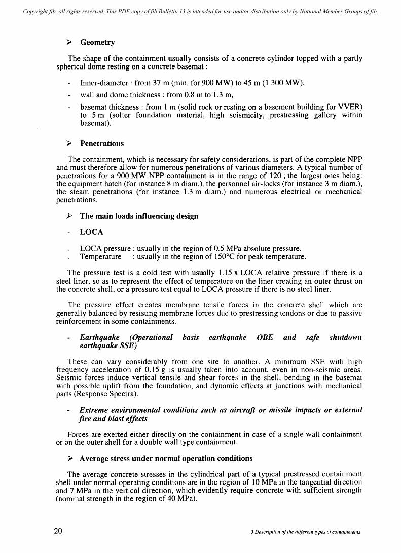
~ Geometry
The shape of the containment usually consists of a concrete cylinder topped with a partly spherical dome resting on a concrete basemat :
Inner-diameter: from 37 m (min. for 900 MW) to 45 m (1 300 MW),
wall and dome thickness: from 0.8 m to 1.3 m,
basemat thickness: from 1 m (solid rock or resting on a basement building for VVER) to 5 m (softer foundation material, high seismicity, prestressing gallery within basemat).
~ Penetrations
The containment, which is necessary for safety considerations, is part of the complete NPP and must therefore allow for numerous penetrations of various diameters. A typical number of penetrations for a 900 MW NPP containment is in the range of 120 ; the largest ones being: the equipment hatch (for instance 8 m diam.), the personnel air-locks (for instance 3 m diam.), the steam penetrations (for instance 1.3 m diam.) and numerous electrical or mechanical penetrations.
);> The main loads influencing design
LOCA
LOCA pressure: usually in the region of 0.5 MPa absolute pressure. Temperature : usually in the region of 150°C for peak temperature.
The pressure test is a cold test with usually 1.15 x LOCA relative pressure if there is a steel liner, so as to represent the effect of temperature on the liner creating an outer thrust on the concrete shell, or a pressure test equal to LOCA pressure if there is no steel1iner.
The pressure effect creates membrane tensile forces in the concrete shell which are generally balanced by resisting membrane forces due to prestressing tendons or due to passive reinforcement in some containments.
Earthquake (Operational basis earthquake OBE and ,fiafe shutdowll earthquake SSE)
These can vary considerably from one site to another. A mInImUm SSE with high frequency acceleration of 0.15 g is usually taken into account, even in non-seismic areas. Seismic forces induce vertical tensile and shear forces in the shell, bending in the basemat with possible uplift from the foundation, and dynamic effects at junctions with mechanical parts (Response Spectra).
Extreme environmental conditions such as aircraft or missile ilnpacts or external fire and blast effects
Forces are exerted either directly on the containment in case of a single wall containment or on the outer shell for a double wall type containment.
)i;> Average stress under normal operation conditions
The average concrete stresses in the cylindrical part of a typical prestressed containment shell under normal operating conditions are in the region of 10 MPa in the tangential direction and 7 MPa in the vertical direction, which evidently require concrete with sufficient strength (nominal strength in the region of 40 MPa).
20 3 Description of the d(lferent types of containments
Copyright fib, all rights reserved. This PDF copy of fib Bulletin 13 is intended for use and/or distribution only by National Member Groups of fib.
~ The main structural components
Liner
Most PWR containments have a metallic liner of about 6 mm thick on the inner face of the containment. The liner provides leak tightness whereas the concrete (reinforced or usually prestressed) ensures stability and resistance to loads. The concept is clear and satisfactory although the difficulties are numerous and require careful design and construction due to the:
amount of welding and associated weld inspections,
stresses at junctions with penetrations and at all discontinuities,
thermal effects creating additional outward forces, which are exerted on the concrete and so require a high density of connectors to concrete to prevent buckling,
avoidance of yielding in normal operating conditions which might create tensile forces in the liner after accidents.
Contaimnents with a steel liner are usually single wall structures, as imposed criteria for leakage in case of an accident are satisfied.
Single or double wall concept
The basic idea is the separation of two types of actions:
internal action (such as pressure, temperature, local forces) acting on the inner (usually prestressed) she II,
external actions or events (such as missiles), acting on the outer shell.
The double wall concept improves the control of any possible leakage through the inner containment, which would then be collected in the annulus between inner and outer shell which is maintained under slightly negative pressure. In case of an accident, any radioactive leakage would then be collected, filtered and rejected. A steel liner is no longer necessary as the limited leakage through the inner containment concrete is sufficiently lovy' to be collected without difficulty. For this reason the acceptable rate of leakage through the inner containment is higher than the acceptable rate of leakage through a single wall containment which is not collected, and goes directly into the environment.
The double wall concept also ensures better protection of the inner equipment in the case of severe environmental conditions sllch as missiles or aircraft crash.
It has, however, the inconvenience of lengthening all the pipes coming out of the containment (such as the secondary steam piping system) and also creates numerous additional penetrations through the concrete of the outer shell.
In the US, Russia, Japan and the Ukraine, the favoured concept is that of a single wall containment.
In France the double wall concept has been applied to all reactors of the 1300 and 1400 MW series accompanied by the omission of the steel liner of the inner containment. The leakage of the inner containn1ent is measured during the preoperational pressure test and also periodically tested so as to ensure that it can be collected safely in the annulus.
In Belgium, the latest containments are of the double wall design with a steel liner on the inner shell.
fib HIIlletin 13: Nudell/' ('olltailill/L'J1(1 21
Copyright fib, all rights reserved. This PDF copy of fib Bulletin 13 is intended for use and/or distribution only by National Member Groups of fib.
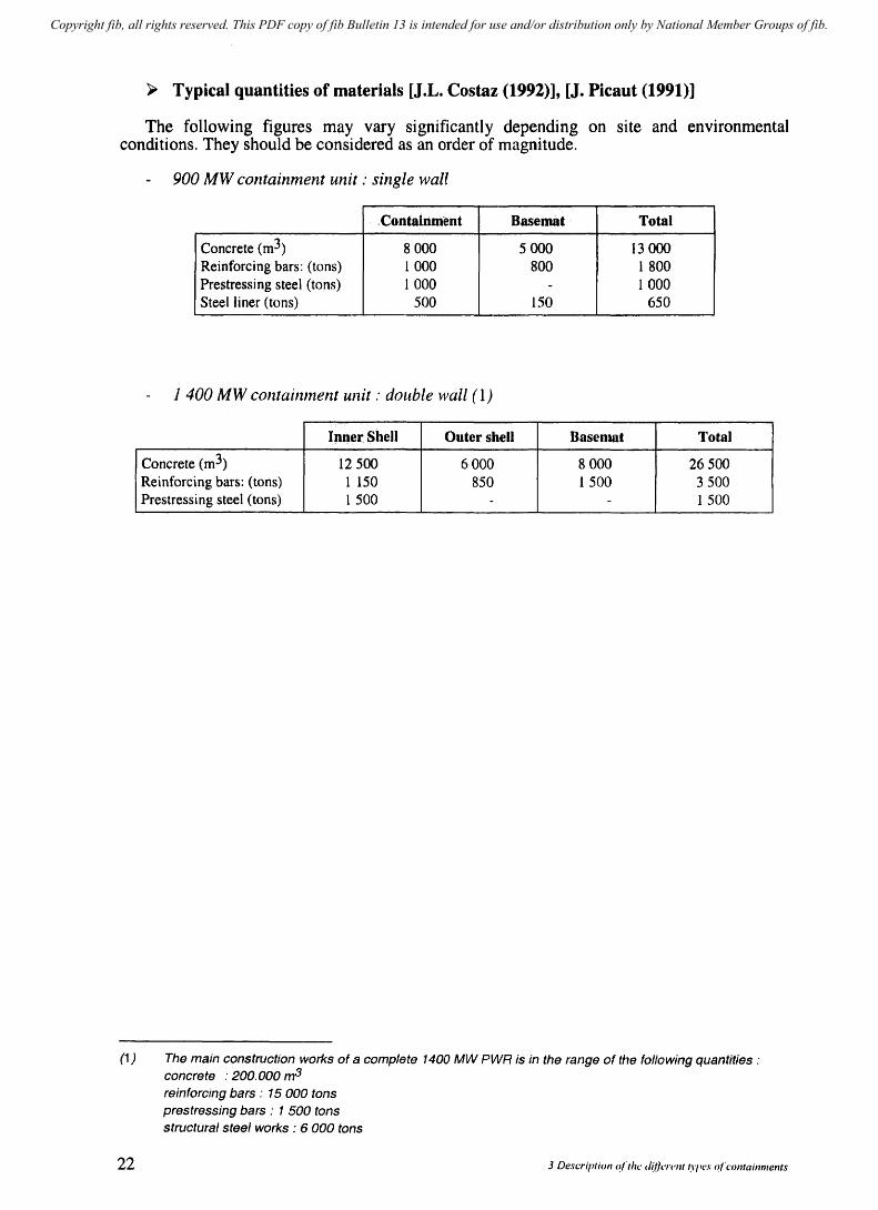
~ Typical quantities of materials [J.L. Costaz (1992)], [J. Pic aut (1991)]
The following figures may vary significantly depending on site and environmental conditions. They should be considered as an order of magnitude.
900 MW containment unit: single wall
. Containment Basemat Total
Concrete (m3) 8000 5000 13 000 Reinforcing bars: (tons) 1000 800 1 800 Prestressing steel (tons) 1 000 - 1 000 Steel liner (tons) 500 150 650
1 400 MW containment unit : double wall (1)
Ipne~ Shell Outer shell Basemat Total
Concrete (m3) 12500 6000 8 000 26500 Reinforcing bars: (tons) 1 150 850 1500 3500 Prestressing steel (tons) 1 500 - - 1 500
(1) The main construction works of a complete 1400 MW PWR is in the range of the following quantities: concrete : 200. 000 m3
reinforcing bars: 15 000 tons prestressing bars: 1 500 tons structural steel works: 6 000 tons
22 3 Description o(lhe "Wi/rl'lJ( ~I'/'('S o(containments

Copyright fib, all rights reserved. This PDF copy of fib Bulletin 13 is intended for use and/or distribution only by National Member Groups of fib.
',~ "-':I". ; "-l,j "-
-.~~.~ ---~~"-~~-.-.- ! .-~- --.-.-
fib Bulletin /3 .. Nuclear containments
0
t ~
~ ... ~
~ ~ '-
H 0
I
"? f':I ...; .~ ~
d· ..
t ~ ... j ,§J '" !! ~
\l t!
I ... I
f':I ...; .~ ~
----------j -----------
--E -tr-
lM .. ____ ...
.... .. . _--"l."" ..... --
$ ~ ~ f':I ..... ~ ~ '-c:IQ :::: '" ~ '" .!;i ~
'\ I
_..Jr.._ ,. f':I ...; .~ ~
23

Copyright fib, all rights reserved. This PDF copy of fib Bulletin 13 is intended for use and/or distribution only by National Member Groups of fib.
3.2.2 Boiling water Reactor (BWR)
~ Typical containlllents
- Kashiwazaki - Kariwa 7 ABWR 1356 MW (Japan) See Fig. 2.3-3
- Oskarshamn 3 BWR 1 160 MW (Sweden) See Fig. 2.3-4
- Gundremmi ngen 2B BWR 1 344 MW (Germany) See Fig. 2.3-5
For more detai led information see Annex 1.
~ Geometry
The general shape is again a cylinder, resting on a thick slab and topped with a prestressed slab with a metallic removable lid to enable direct access to the reactor vessel. The containment volume (in the region of 12000 m3) is much less than for the PWR system, as the only equipment within it are the reactor pressure vessel and the dry and wet well. The overall dimensions for a 1200 MW BWR unit are in the region of 26 m internal diameter and 35 m in height and for a ABWR 1350 MW unit, in the region of 29 m internal diameter and 29.5 m in height.
The containment is a single wall type but is integrated in the reactor building which provides protection from environmental loads. There is a steel liner of 6 to 10 fnm thick.
~ Penetrations
The total number of penetrations is in the order of 100. As there is more limited equipment within the containment, there is no equipment hatch. The personnel air locks are in the region of 2.5 m diameter.
~ The main loads influencing design
The same type of loads as for a PWR are taken into account. A LOCA is in the region of 0.60 MPa absolute with a temperature of 170°C.
The pressure test is run at L 15 x relative LOCA pressure. The aircraft impact is resisted by the reactor building.
24 3 Descriptioll of the different types of containments
Copyright fib, all rights reserved. This PDF copy of fib Bulletin 13 is intended for use and/or distribution only by National Member Groups of fib.
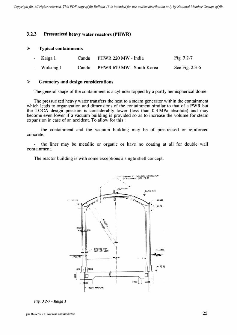
3.2.3 Pressurized heavy water reactors (PHWR)
~ Typical containments
Kaiga 1
Wolsong 1
Candu
Candu
PHWR 220 MW - India
PHWR 679 MW - South Korea
~ Geometry and design considerations
Fig. 3.2-7
See Fig. 2.3-6
The general shape of the containment is a cylinder topped by a partly hemispherical dome.
The pressurized heavy water transfers the heat to a steam generator within the containment which leads to organization and dimensions of the containment similar to that of a PWR but the LOCA design pressure is considerably lower (less than 0.3 MPa absolute) and may become even lower if a vacuum building is provided so as to increase the volume for steam expansion in case of an accident. To allow for this:
the containment and the vacuum building may be of prestressed or reinforced concrete,
the liner may be metallic or orgamc or have no coating at all for double wall containment.
The reactor building is with some exceptions a single shell concept.
200 51
~l l
Fig. 3.2-7 - Kaiga 1
fib Bulletin 13: Nuclear containments
I .,j,,,,,-
OPENING FOR MAIN AIR LOCI<
_ OPENING TO F'AC1UT"Tl INSrALLAT1QN , ''', OF EOUIPMENT (SEE FlC."
'I I
14:zej60 I
1 f!.:1 oo.c,
.,,~
---'~"I.-l --+------;-i"- d OJ
El.~?,8j
.,.-'
2000 L 1 85
25
Copyright fib, all rights reserved. This PDF copy of fib Bulletin 13 is intended for use and/or distribution only by National Member Groups of fib.
4 Safety
4.1 General [J. Libmann (1997)]
Although the main subject of this document is the containment, it is also necessary to make a brief but more general presentation of safety of NPPs, of which the containment is a very important component.
4.1.1 Definition
Safety is the set of technical and organization provisions which ensures that at all stages of the lifetime of a plant its existence and operation will limit the risks to that can be considered as acceptable for its staff, the public and the environment.
4.1.2 Safety issues for NPPs
The most important issue, the prevention of release of radioactivity, is obtained by three successive barriers:
the fuel elements cladding,
the primary circuit (core vessel + piping loops connecting pumps, steam generators and pressurizer),
the containment.
The containment is the third and last barrier. Its integrity under any normal or accidental conditions must be ensured and for this reason it is closely controlled by operators and safety organ izati ons.
4.1.3 Methods for reaching safety
- Prevention to prove the suitability of the materials to imposed conditions, the margins and technical limits during the entire operational lifetime.
- Surveillance to ensure the margins are maintained duri ng the lifetime of the plant.
- Security actions in case of an accident where the technological limits of materials are overpassed to prevent or limit radioactivity dissemination.
fib Bulletin J 3: Nuclear containmel/ts 27
Copyright fib, all rights reserved. This PDF copy of fib Bulletin 13 is intended for use and/or distribution only by National Member Groups of fib.
4.2 Safety organization
The two main actors are: the Public Authorities and the Plant Operator.
The Public Authorities and their representative organizations and technical support are known as the Safety Authorities. They define the general regulations and the objectives of safety and verify that these are met throughout the life of the plant.
The Plant Operator known also as the Licensee, assisted by the Architect Engineer and Constructor is responsible for the safety of the plant as he alone can take the necessary steps in the case of an emergency. He must obtain, prior to any operation of the plant, approval by Safety Authorities that the safety requirements are met.
Such an arrangement meets the recommendations of the International Atomic Energy Agency (lAEA) in Vienna.
The independence of the two main participants is considered as favourable to safety and does not mean the absence of technical dialogue.
4.3 Safety reports and regulations
4.3.1 Safety reports are presented by the Architect Engineer and operator to Public Authorities for approval prior to any authorization of construction, commissioning start-up, operation, closing, decommissioning and dismantling of the plant.
The safety reports based on regulation are approved and then have a regulatory value.
4.3.2 Regulations must always be approved by the Safety Authorities. They may be written by the safety authorities themselves or by the architect engineer, the operator and more generally by the nuclear industry.
28
Depending on the country's practice and specific requirements, its number of operators and nuclear suppliers, the extent of guidance by safety authorities to the nuclear industry and operators may differ. For example, although the set of regulations is complete and self supporting both in France and in the US the safety authorities are more guiding in the US where operators are more diverse. But the general organization is basically similar.
In France for instance:
- The documents written by safety authorities are:
general technical regulations with many organisational aspects, fundamental safety rules presenting clearly the goals to be achieved.
- The documents written by nuclear industry or the operators and necessarily analyzed and approved by safety authorities are:
the rules for conception and construction (RCC) relating to :
- civil works (RCC-G) - mechanics CRCC-M) - electrical CRCC-E) - fire protection CReC-I)
fuel (RCC-C)
4 Safety
Copyright fib, all rights reserved. This PDF copy of fib Bulletin 13 is intended for use and/or distribution only by National Member Groups of fib.
RCC-G which is the basic regulatory document for conception, design and construction of nuclear civil works (and especially the containment) meets the safety authorities regulations and is approved by safety authorities. RCCG refers to the different civil works codes applied in France (such as BAEL and BPEL) or internationally (model code CEB 78) and adapts and completes them where necessary.
specific documents for a particular plant (such as site conditions, seismic levels, external agression risk, etc.).
In the US the regulatory authority NRC, on the basis of the general design criteria for NPPs and 10 CFR 50, is more guiding through Reg guides and standard review plans for safety reports requirements, the basic regulatory document for design and construction being ASME Section III Division 2 and ACI 359 which complies with NRC guidelines.
In Sweden and Finland the US guides have been followed in principle.
In Japan the licensing procedures are basically not much different from other countries such as France and the USA. Although the safety of nuclear power plants are double-checked by the Japan Atomic Energy Safety Commission, the Ministry of International Trade and Industries (MITI) plays a major role in licensing review.
The regulatory documents relating to concrete containment vessels are as follows:
- Ministry of International Trade and Industries (MITI) Notice 452 "Technical Standard for Concrete Containment Vessels for Nuclear Power Plants" (1990),
- Ministry of International Trade and Industries (MITI) Notice 501 "Technical Standard for Structural Design of Mechanical Components of Nuclear Power Facilities" (1980),
- Japan Atomic Energy Safety Commission "Regulatory Guide for Aseismic Design of Nuclear Power Reactor Facilities" (1981),
- Japan Electrical Association" Technical Guidelines for Aseismic Design of Nuclear Power Plants" (1984), JEAG 4601-1987 translated as NUREG/CR-6241, BNL-NUREG-52422.
4.4 The concept of "in depth defence"
4.4.1 The different levels of accidental situations
Although the safety requirements tend to help avoid accidental situations, it is assumed that an accident may occur. The approach consists of classifying the situations into five different levels and imposing the actions aimed at limiting the consequences to one level and then avoiding them reaching the next and worse level (see INSAG 10 document by IAEA).
The successive levels are as follows:
1 st level : Prevention of failure of any component under normal operating conditions, including the most severe conditions (operational basis earthquake for instance), through prudent design and quality of construction.
2nd level Prevention of the development of accidental situations through reliable regulation systems (temperature and pressure for instance) enabling the plant to stay within operational conditions even in cases of a deviation. A progratTI for checking abnormal conditions is required (for containments: in service inspection and pressure tests).
fib Bulletin 13: Nuclear containments 29
Copyright fib, all rights reserved. This PDF copy of fib Bulletin 13 is intended for use and/or distribution only by National Member Groups of fib.
3rd level
4th level
5th level
In spite of the actions taken in view of avoiding the first two levels, a series of incidents and accidents are postulated (deterministic approach) including instantaneous and complete rupture of a primary loop (LOCA). \ '
Specific measures are taken to limit the effect of such accidents and avoid radioactive release. They include systems which are only related to safety and not to the operating capacity of the plant:
water injection systems in the primary loop and in steam generators and release of containment,
existence of a containment structure capable of withstanding the pressure and temperature effects while remaining sufficiently leak tight.
The risk of multiple failure leading to accidents which are not included in level 3 are considered, which may lead to more severe conditions such as core fusion and as a consequence a higher risk of radioactive release.
The aim of level 4 is to reduce the probability of occurrence of such failures and to maintain as high a level of radioactive confinement as possible.
As a contingency, postulated failure of the first 4 levels (including radioactive risks) is assumed, and plans for protection, information and evacuation of the public are set up.
4.4.2 Loss of coolant accident (LOCA)
This is considered as the basic accidental load for the containment whatever the initiating event to this accident. It has been seen in § 4.4.1, that LOCA is a 3rd level accident which requires a containment capable of withstanding the resulting effects. This capability is checked before start-up by the structural integrity pressure test (lSIT).
30
~ Simplified description
A simplified presentation of the postulated accident is the following:
- a complete and instantaneous piping rupture occurs in the prilnary loop connecting: vessel - steam generator-pump at the worst position (between pump and vessel: cold branch). Immediate loads (in the region of 15 MN) are applied to the reactor huilding internal structures.
- Pressure lowers rapidly in the loop while pressure and temperature increase in the containment.
- The lack of water (replaced by steam) around fuel elements reduces the nuclear chain reaction even before automatic lowering of control rods, but heat (over 800ae) and pressure increase in the fuel elements with a risk of rupture of the zircalloy sheath.
- Water from the accumulator is automatically emptied by gravity into the primary loops. The safety water injection system then comes into operation automatically and the water level increases in the core while the fuel elements stay surrounded with steam due to their temperature and are cooled progressively. The aspersion system of the containment comes into operation simultaneously. Pressure and temperature reduce progressively in the containment. The cooling by recirculating cold water may last for months.
4 Safety
Copyright fib, all rights reserved. This PDF copy of fib Bulletin 13 is intended for use and/or distribution only by National Member Groups of fib.
» The effects on the containment
The escape of steam creates a fast (but not dynamic) increase in pressure (in the region of 0,5 MPa absolute in a PWR) and simultaneously an increase in temperature (in the region of 150°C).
After the initialisation of the safety injection systems, the pressure and temperature lower gradually (see fig. 6-6.1).
>- Calculation of the loads on containment in case of LOCA
The effects of LOCA are calculated by modelling the thermo hydraulic behaviour of the system throughout the process of the accident.
The calculations are carried out with enveloping assumptions so as to reach conservative results.
The calculations are usually carried out by the supplier and strictly controlled by the safety autholities.
4.5 The probabilistic safety approach
The prohabilistic approach goes far beyond a probabilistic evaluation of seismic or aircraft crash risk.
As early as 1972 studies concerning risks induced by NPPs were undertaken by Professor N.C. Rasmussen.
The RasrTIussen reports define sequences leading to situations for which the containment is not designed such as effects which may be induced by core fusion: degradation of containment basemat, hydrogen combustion (defiagration, detonation), progressive and unlimited increase in pressure.
The Rasmussen repol1, as well as the Three Mi Ie Island and Chemobyl accidents, reinforced the conviction of the necessity for a reliable containment even in the case of what was called severe accidents not having been taken into account as design loads.
This leads to two consequences:
Measures were taken to avoid the consequences of the postulated severe accidents or discard them as of excessively low probability:
verification that combustion of hydrogen produced by core melting would not induce rupture of the containments,
verification that the probability of detonation occun"ence is very low,
measures taken to improve the integrity of the basemat (drains and instrumentation tubes in basemat suppressed, filling gap between the basemat and foundation if anti-seismic bearings exist),
ITIeaSUres taken to avoid permanent pressure increase by limiting the pressure by relief valves and using sand filters for the emitted gas.
fib Bulletin 13: Nuc/ear C01lfainments 31

Copyright fib, all rights reserved. This PDF copy of fib Bulletin 13 is intended for use and/or distribution only by National Member Groups of fib.
Studies of the sequences of accidental events leading to a catastrophic scenario, analysis of the probabilities of occurrence of the different stages in the sequence and of the methods to reduce the successive probabilities were undertaken.
Due to its consequences, the core fusion is the worst situation to encounter with initiating events such as :
LOCA, rupture of steam generator tubes, failure of the cold water cooling system, failure of water supply to steam generator, failure of electric supply, failure of the urgent stop system of the reaction.
As an example the initial event could be the failure of electrical supply which has a probability evaluated by taking into account the existence of two independent external sources as well as the existence of spare diesel generators. The consequence of this failure results among others in :
a drop of the control rods stopping the nuclear reaction (favourable), stopping of turbo pump (ASG), loss of information in the control room after one hour on batteries, etc.
Each of the resulting events and their consequences in terms of probabilities and considering the duration of the initial event (complete failure of electrical supply), is analysed to make a final probability evaluation of the severe accident (core fusion).
Such studies were undertaken as early as the late seventies to reduce risks on materials as well as on human errors during critical or accidental situations.
It is usually assumed that the reactor is safe if, all events having been taken into account, the risk per unit is less that 10-6 per year. If one assumes ten possible initiating events there is a probability in the region of 10- per year per event.
4.6 The observance of safety rules for the containment 4.6.1 Quality Assurance
Cornpliance with Quality Assurance Programs, initiated in the sixties by the nuclear industry, is now common to most industrial activities. The ISO 9000 rules for Quality Assurance concern all stages of the lifetime of the plant: conception, construction, operation, decommissioning and dismantling. For the NPP and especially the containment additional obligations or specifications have to be met such as the duration of conservation of documents, independent control, etc. The control and auditing to ensure that the QA program is strictly observed is run by independent and duly qualified organizations.
4.6.2 Design
The designer must prove by means of the safety reports that all safety regulatory requirements are met. In particular approval of the following must be obtained:
the design situations, whether accidental or normal operating, the values of design loads, the combination of loads, the design methods and calculations, the predicted design values for materials.
These may differ depending on the applied set of regulations (see chapter 6). The designer must also demonstrate the quality of his organization for performing the
design.
32 4 S4fety
Copyright fib, all rights reserved. This PDF copy of fib Bulletin 13 is intended for use and/or distribution only by National Member Groups of fib.
4.6.3 Construction
The Constructor must demonstrate:
the quality of materials, the quality of construction, the quality of works organization.
4.6.4 Structural Integrity Test (SIT)
The Operator must demonstrate the satisfactory behaviour of the containment during the pressure test both for the:
structural behaviour: . adequacy between calculated and measured strains . reversibility of deformations and limited cracking (elastic behaviour).
leaktightness The leaktightness criterion is of course different for a single wall containment with a steel liner and a double wall containment with leakage collection in the annular space.
4.6.5 During operation
The operator must demonstrate the satisfactory behaviour of the containment during its life time:
in service inspection (lSI) (all countries),
successive pressure tests for checking structural behaviour and leak tightness during the life of the containment (in some countries),
analysis of the long-term defonnations of the prestressed containment (in some countries).
4.6.6 Decommissioning and Dismantling
The operator remains responsible for the safety of the plant and must maintain adequate surveillance and control of operations (see Chapters 10.5 and 10.8).
4.7 Safety as a permanent quest: Licensing, Reassessment of the plant, Periodic Safety Reviews (PSR) [OECD - NEA, Jan. 2001]
In most countries it is a basic requirement that the operator (licensee) should carry out a continuous review of the Safety of his plant, propose to the Safety Authorities the necessary upgrades if any and after approval proceed to the upgrade.
Adequate quality systems are then necessary to ensure the completeness of the review and to check that safety upgrades are properly recorded and their impact on other safety aspects assessed.
Depending on the country, licences for operating a plant may be valid for a fixed term.
For instance in the US operating licences are limited to a fixed tenn reaching at most 40 years. The operator must demonstrate during this long term operation that the licensing
fib Bulletin 13: NlIc:lear containments 33
Copyright fib, all rights reserved. This PDF copy of fib Bulletin 13 is intended for use and/or distribution only by National Member Groups of fib.
basis is maintained. However Periodic Safety Reviews (PSR) are not requested in the US. Any renewed licence will also be issued for a fixed period not exceeding 20 years.
Fixed term licences are also applied in some other countries including Finland, Mexico, Switzerland.
In Canada operating licences are renewed every 2 years subject to proof given to the Atomic Energy Control Board (AECB) that the risk remains within the original design basis. In particular for the containment it is checked that the leak rate remains acceptable.
The other countries do not have term licences. They generally control long term operation by monitoring operational performance and by comprehensive periodic safety reviews (PSR) usually every 10 years. However reassessment may be required at any time if some changes have occurred such as:
development in codes, regulations, and safety requirements,
evolution of loads whether internal or external or in qualification of materials and their ageing,
new knowledge resulting from operating experience,
effect of changes in the installation on other parts of the plant, for instance on the containment.
The reassessment of the containment, taking into account the previous factors and the present state of the containment evaluated through monitoring measurements and if necessary new structural calculations (probabilistic safety assessment see paragraph 4.8) will enable an updated evaluation of safety margins to be reached, informed decisions of the consequences to be made and whether corrective measures should be implemented or not.
The objectives of these PSRs are:
to prove that the plant is as safe as originally designed,
to show that it will remain safe during the next 10 years,
to compare with the most recent standards and determine which safety improvements are practicable.
The PSR enables both operator and regulator to identify current technical issues and also those that are likely to arise before the next periodic review. The key technical issues are:
correcting deficiencies in the original design of the plant, correcting deficiencies in the original construction of the plant, dealing with the ageing of materials and components, dealing with obsolescent components and procedures, applying modern requirements (as far as reasonably practicable) other technical issues related to public perception.
The key technical issues are completed by general management issues.
The PSR enables to evaluate to what extent the existing plant conforms to the modern standards. But although the impact of a new rule on the plant is assessed, it is usually not required to be totally applied to the existing plant and improvements are those that are reasonably practicable in terms of safety gains and incurred costs. The basic requirement for continued operation remains that the licensing basis of the plant is maintained throughout its life.
34 4 Safety
Copyright fib, all rights reserved. This PDF copy of fib Bulletin 13 is intended for use and/or distribution only by National Member Groups of fib.
4.8 Probabilistic safety assessment of the containment (PSA)
The NPP regulations are based on deterministic engineering criteria and methods. The PSA can be considered as an additional tool for safety evaluation. The goal of a Probabilistic Safety Assessment (PSA) was initially to evaluate the probability in case of a severe accident generating high temperature and pressure inside the containment should result in a significant radioactivity release into the environment.
The analysis of the containment is performed for a number of different fracture or leak failure modes for instance in piping [Granger (1997)].
Depending on temperatures expected under accidental conditions, the pressure corresponding to failure for the different postulated failure modes is calculated taking into account the median mechanical properties of the structural materials, probability laws for variability of these characteristics, and also the reliability and precision which can be expected from the design computations. The results are presented as the median limit pressures for the different failure modes and their variability. The weakest parts of the structure are identified as well as the ratio of reliable failure pressure to design pressure.
It is nowdays considered that a PSA, as a different type of approach, may also be performed for accidents already taken into account in the design of the plant and not only for severe accidents.
PSA incorporates operating feedback and as such appears of growing interest for regulators. However at the present time licensing as well as upgrading and life extension procedures are based on the deterministic approach.
5 The execution of a project
5.1 General
The object of this chapter is to describe the general trend in the development of a new NPP project and show the integration of the containment in the overall project at different stages of the design.
As they are not covered by the technical aim of this document, Administrative procedures, Environmental Assessments and Public Hearings, preliminary site investigations, and the approval of the plant construction and site selection, are not developed hereafter despite their importance.
fib Bulletin J 3: Nuc:lear containments 35
Copyright fib, all rights reserved. This PDF copy of fib Bulletin 13 is intended for use and/or distribution only by National Member Groups of fib.
5.2 The different participants in a project
The first participant is the Utility whose objective is primarily to produce, distribute and sell electricity. He orders the plant to be designed and built.
The requirements of the utility are expressed in terms of plant power capacity, location, cost competitiveness, and schedule of works.
The other agents participating in the project already mentioned in chapter 4 are:
the Safety Authorities, representing the Public Authorities and their representative organizations, who define the safety rules and objectives and verify that they are met,
the Plant Operator (who mayor may not be part of the utilities) whose experience ensures that the plant is adequate for operation, maintenance and availability,
the Architect Engineer who designs the plant, taking into account the requirements of the other three participants. His ability encompasses all disciplines and particularly a thorough experience of the nuclear steam supply system.
5.3 The different stages in the development of a project
One may consider three successive stages:
feasibility or conceptual design phase,
basic design,
detailed design.
5.3.1 Feasibility or conceptual design phase
The aim of the feasibility stage is to produce a plant design concept that fulfi Is the requirements of the utilities, that is easy to operate and maintain, meets the safety autholities' requirements and takes into account the experience gained from previous generations of NPPs.
This stage is performed after deciding upon:
the essential design and operating data
for NSSS Power, general characteristics of the reactor coolant system and of the core,
for containment: Type of containment (concrete or steel, single or double wall),
36 5 The execution of a project
Copyright fib, all rights reserved. This PDF copy of fib Bulletin 13 is intended for use and/or distribution only by National Member Groups of fib.
the regulations, the safety requirements such as those concerning leak tightness or severe accidents, loads and imposed conditions such as at seismic level, soil conditions, external hazards, etc. At this stage the design is usually performed for a maximum enveloping seismic level and a range of soil conditions.
The feasibility study for structures includes:
a general layout and building arrangements of the plant for the complete nuclear island,
a predimensioning of the structures including the containment's main overall geometry and determination of the resulting pressure under accidental conditions. the locations and dimensions of main penetrations and buttresses in accordance with neighbouring buildings, a predimensioning of the basemat, wall and dome thicknesses and a preliminary study of the prestressing pattern to ensure its feasibility,
a preliminary cost estimate.
The type of approach for the structural design is usually at this stage mainly hand calculations, parametric studies (influence of containment radius and volume on plant layout and accidental pressure) positioning of penetrations in relation to building arrangement, optimizing the general layout in relation with seismic forces, etc.
The close interactions between the NSSS, the structural design and the inputs from all project participants lead to an extensive use of computer aided tools for solving interface problems and optimizing the design process.
5.3.2 Basic design
The duration and cost of the conceptual and then the basic design mean that the basic design can be adapted with only minor changes to any site within the chosen maximum seismic level and range of soil conditions (from soft soil to hard rock). Furthermore the cost of construction (for civil works but mainly for equipment) is considerably lowered by the effect of the economic benefit of a series of plants.
At the basic design stage the dimensions of each building are precisely defined so as to avoid later modifications which might affect the plant and prevent benefit from the series effect.
The precise definition of the structures requires the overall computations to be performed at this stage including the envelope of the general loads: earthquake, aircraft impact, accidental pressure and temperature, pressure test, severe accidents as well as the main accidental local loads which may be exerted on the structure (main piping and anchorage of heavy materials in the concrete structure).
If prestressed, the prestressing forces in the containment are introduced in the computation finite element models which requires a precise and final definition of the prestressing pattern. The basic design drawings for the containment include a complete set of formwork drawings, including main penetrations and main forces exerted at junctions with piping, a precise definition of the prestressing pattern, and local drawings of the re-bars in complex areas such as the basemat-wall junction, equipment and personnel hatch and dome junctions. It should be noted that the re-bar drawings at basic design stage are only supposed to prove the feasibility as later modifications of the reinforcement will not affect the interfaces with the equipment.
fib Bulletin J 3: Nuclear containments 37
Copyright fib, all rights reserved. This PDF copy of fib Bulletin 13 is intended for use and/or distribution only by National Member Groups of fib.
5.3.3 Detailed design and construction drawings
A precise definition of seismic and soil conditions at the construction site is now known.
The process (plant equipment) can then confirm the general internal loads and specify all local interactions with structures whether minor penetrations or local forces.
The overall static and dynamic finite element calculations are reperforrned using the site seismic and soil conditions. They are completed by all necessary detailed calculations for determination of local reinforcement.
Detailed drawings are produced lift by lift for formwork, liner, prestressing, and reinforcement so as to limit the work of the contractor and the problems of construction.
Detailed technical specifications for construction and erection sequences are established.
5.3.4 Duration of the different design phases
~ Conceptual design phase
The conceptual design phase only starts after sufficient experience has been gathered, technical progress made, and an evolution in regulations and safety requirements encountered to justify a new concept.
After a decision has been taken, two to three years can be considered as a minimum for an experienced Architect Engineer to perform the conceptual design phase.
This phase can be omitted for future projects with a similar general concept.
~ Basic design phase
A duration of two to three years can also be considered acceptable.
» Detailed design
After the decision to construct on a particular site has been made, site conditions have to be determined which requires soil testing, seismic and climatic evaluations and this phase lasts at .least a year. Detailed design can then begin. Overall calculations based on the determined site conditions and production of construction drawings for the lower parts (basemats) of the structures cannot be performed in less than one year, and should be transmitted to the contractor at least six months before construction starts for programming and planning reasons. The constructor who has, meanwhile, canied out the main site excavations can then start construction which should last on average four to five years before erection of the unit is completed.
The detailed design process for the civil works can be performed in approximately three years in total but minor modifications due to the plant or requested by the contractor usually take place until civil work construction ends.
A typical and very rough schedule for the complete process, under the very optimistic and highly improbable assumption that no delays are encountered between the different phases of design should then be as given in Table 5.3-1.
38 5 The execution of a project
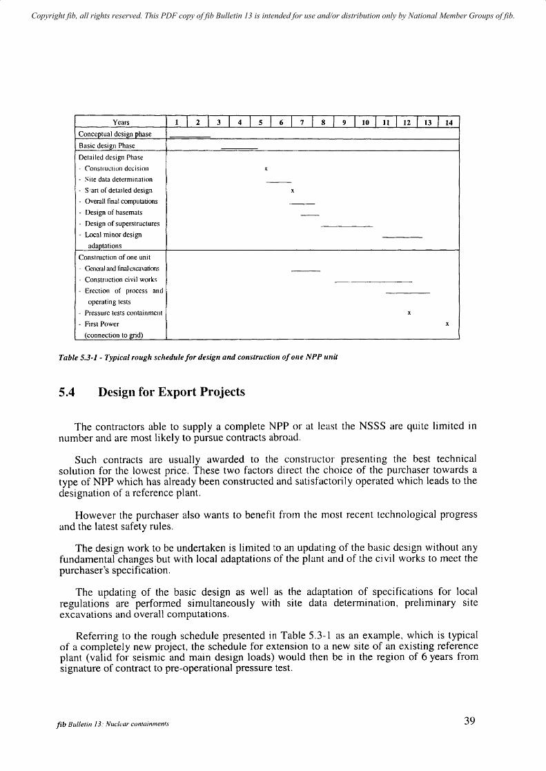
Copyright fib, all rights reserved. This PDF copy of fib Bulletin 13 is intended for use and/or distribution only by National Member Groups of fib.
Years 1 I 2 I 3 I 4 I 5 I 6 I 7 I 8 1 9 I to I ttl 12 / 13/ 14
Conceptual design phase
Basic design Phase
Detailed design Phase
- Construction decision x - Site data determination --- S'an of detailed design x
- Overall final computations --- Design of basemats --- Design of superstructures
- Local minor design
adaptations
Construction of one unit
- General and lina] excavations
- Construction civil works
- Erection of process and
operating tests
- Pressure tests containment x - First Power x
(connection to grid)
Table 5.3~1 - Typical rough schedule for design and construction of one NPP unit
5.4 Design for Export Projects
The contractors able to supply a complete NPP or at least the NSSS are quite limited in number and are most likely to pursue contracts abroad.
Such contracts are usuaIJy awarded to the constructor presenting the best technical solution for the lowest price. These two factors direct the choice of the purchaser towards a type of NPP which has already been constructed and satisfactorily operated which leads to the designation of a reference plant.
However the purchaser also wants to benefit from the most recent technological progress and the latest safety rules.
The design work to be undertaken is limited to an updating of the basic design without any fundamental changes but with local adaptations of the plant and of the civil works to meet the purchaser's specification.
The updating of the basic design as well as the adaptation of specifications for local regulations are performed simultaneously with site data determination, preliminary site excavations and overall computations.
Referring to the rough schedule presented in Table 5.3-1 as an example, which is typical of a completely new project, the schedule for extension to a new site of an existing reference plant (valid for seismic and main design loads) would then be in the region of 6 years from signature of contract to pre-operational pressure test.
fib Bulletin J 3: Nue/car containments 39
Copyright fib, all rights reserved. This PDF copy of fib Bulletin 13 is intended for use and/or distribution only by National Member Groups of fib.
6 The main factors governing design
This chapter is limited to design and does not include consideration of the specifications for construction materials.
6.1 The design parameters and mechanical properties of materials
The design parameters necessary for design are independent of the design code but specifications that are used to define the design values may vary depending on the design codes that are used. One may distinguish between:
The values imposed or proposed by regulations:
general codes and standards complemented by particular codes and specifications devoted to the design and construction of NPP when not included in general codes,
specific design criteria and specifications for one particular NPP.
The values resulting from testing
qualification tests and certifications, mainly for steel components,
laboratory and on site testing, mainly for concrete and geotechnics but also for prestressing (friction factor).
The values used for design, resulting as mentioned previously either from codes or testing but which are checked throughout construction.
The presentation in Table 6.1-1 of the origin of main design values, whether derived from regulations or tests, should in no way be considered as exhaustive but as typical. For more precise and detailed information one must refer to the different existing codes, standards, rules and specifications (see para. 6.3.2. and corresponding tables).
The design parameters that are presented in Table 6.1-1 do not include those such as aggregates, admixtures, cement, or the chemistry of water, which are necessary for specifying the concrete but are not directly used for designing the containment.
fib Bulletin 13: Nuclear containmenTS 41

Copyright fib, all rights reserved. This PDF copy of fib Bulletin 13 is intended for use and/or distribution only by National Member Groups of fib.
Materials The considered Values from regulations Values from testing Values
checked
during
design parameter General & Specific Qualification Laboratory construction
parth~ular design criteria tests and site
codes certification testing
Concrete CompressIve strength 1 2 x x
Young's moduli and Poisson ratio (a). 1 2 x x
Shrinkage I 2 x
Creep I 2 x
Thermal coefficients (b) 2
Density 2
Damping factors 2
Stress/Strain curves 2
Re bars Yield stress 2 x
Young's modulus 2
Stress/Strain curves 2
Steel liner Grade 2 x
Yield stress average 2 x
Yield stress minimum 2 x
Young's moduli & Poisson's ratio (a) 2 x
Thermal coefficients (b) 2
Stress/Strain curves 2
Prestressing Type of tendon I 2 x
Ultimate tensile stress I 2 x
Tensile yield stress I 2 x
Young's Modulus 2 x
Relaxation losses I 2 x
Max. stress at tensioning 2 x Anchorage slip I 2 x x x Friction factors 1 2 x x Dimensions of ducts 1 2 x Allowable curvatures I 2 x
Stress/strain curves 1 x Corrosion protection 1 2 x
Geotechnics Soil strata characteristics 2 x
Moduli & Poisson's ratios 2 x
Water table levels 2 x
Damping ratios I 2
Nota: (a) Young's moduli & Poisson's ratio distinguish dynamic values. short term values, long term values. and temperature effects.
(b) Thermal coefficients include: thermal expansion coef, thermal conductivity cocf. transmission coer. between air and concrete, heat capacity
Table 6.1-1 - The origin o/the main design values 1. Proposed - 2. Imposed
42 6 The main/actors governing design
Copyright fib, all rights reserved. This PDF copy of fib Bulletin 13 is intended for use and/or distribution only by National Member Groups of fib.
6.2 The loads (or actions) exerted on the containment
6.2.1 Load categories
The load categories can be classified as :
those relative to the external hazards such as wind, earthquake, explosion, missiles and aircraft crash,
those in relation to operation or accidental reactor conditions such as pressure during Structural Integrity Test (SIT) or pressure and thermal effects in the case of the design basis accident (DBA).
Depending on the overall concept of the containment (single shell or double shell), the loads may be exerted entirely on one shell (single wall containment) or separated between inner and outer shells (double wall containment).
The elementary effects to be taken into account in design are not basically dependent on the type of regulation that is applied, but the values and combination of the loads or actions and also the safety factors on loads and the stresses in materials are dependent on the applied regulations.
Depending on the regulations the loads may be classified differently (see table 6.2-1 classification of actions on containment for three different sets of regulations chosen as examples) :
ASME for containments,
RCCG (French Design and Construction rules for PWR) [EDF-RCCG (1998)],
MITI notice 4.5.2 (Japanese notice for concrete containment vessel) [T. Kuroda et al (1993)].
It should also be mentioned that depending on the code and of the countries practice, some differences may appear (see paragraph 6.3.1) as well in the loads as in the load combinations.
fib Bullefin J 3: Nuclear containments 43

Copyright fib, all rights reserved. This PDF copy of fib Bulletin 13 is intended for use and/or distribution only by National Member Groups of fib.
• 1.
ASME
Service loads Normal loads
D. Dead loads including hydrostatic and pennanent equipment.
L. Live loads including equipment
movable
RCCG
• Permanent actions
Dead weight. Weight of fixed equipment Lateral thrust of earth and table
MITI (Notice 452)
• Load Category 1 1. Normal Operating D. Dead weight including fixed
equipment.and others fixed water L. Live loads including movable
equipment and others
F. Prestress loads Thermal actions, shrinkage, creep F. Prestress loads G. Loads from relief valves or other devices
To Thennalloads during Normal Operating (N.O.) Ro Pipe reaction during N.O.
Ground reaction Prestressing
• Variable actions
Pv Pressure variation containment
inside Loads during construction
or outside Operating loads
Climatic actions Thermal actions
2. Construction loads Variation of water table D. L. F, T". applicable but with construction Pressure during SIT conditions Pressure variations during N.O.
3. Test loads • Accideluai actions D, L, F, based on test conditions SSE PI: pressure during SIT (Standard Integrity Explosion
Test) Tt : thermal effects during SIT
• Factored loads
1. Severe environmental loads w design wind En: OBE (Operational Basis earthquake)
2. Extreme environmental loads (1)
ESS : SSE (Safe Shutdown Earthquake) Wr : Tornado
3. Abnormal loads P Q : Design pressure load (Design basis accident) T E : Thermal Effects DBA Ra: Pipe reaction and local effects due to DBA
Aircraft crash Piping rupture
Site nooding
Fire DBA Internal missiles
Pl. Nonnal Operating Pressure R 1. Normal Operating Piping Loads TI. Normal Operating Thermal Loads • Load Category 11 1. Safety relief valve operating D. L. F, PI, RI, Tl.
2. Testing D, L. F.
3. Snow Snow load with Normal Operating loads
• Load Category III 1. Storm Wind loads with Normal Operating Loads
2. S 1 seismic S I seismic load with Normal Operating Loads 3. L(I)-accident (including peak
loads immediately after LOCA) D, L. F. P2 - LOCA accident pressure R2 - LOCA accident pressure T2 - LOCA accident thermal loads 4. L(2)-accident + SI Oong-sl1l)taining
loading condition lOe-l year after LOCA when combined with SI)
• Load Category IV 1. S2 seismic D. L. F, PI, R 1. S2 seismic load 2. L(3) accident D, L. F, R2. P3 1.5 times design pressure 3 .J -accident D, L, F. and Jet Force 4. L(4)-accident + SI D, L, F, P2, R2, and S) seismic load where the maximum pressure and piping loads are taken into account 5. L(5)-accident + snow D, L F. P2, R2 and Snow load 6. L(6)-accident + Storm D, L, F. P2, R2, and Wind load
Note (J )Aircraft impacts. external explosion or fire effects should be classified as Extreme ellvironmentalloads
Table 6.2-1 - Classification of actions 011 cOlltainments
44 6 The main/actors governing design
Copyright fib, all rights reserved. This PDF copy of fib Bulletin 13 is intended for use and/or distribution only by National Member Groups of fib.
6.2.2 Who defines the values of loads?
All load values and accidental scenarios have to be approved by the Safety Authorities. The different load values are defined and proposed to the Safety Authorities by the Architect Engineer (AE) :
For External hazards: existing regulations are complemented by enquiries and specific studies, investigations and evaluations
For Normal and construction loads the A.E. defines the loads on the basis of his experience as designer and user
For Abnormal loads (pressure, thermal effects, pIpe reactions), the A.E. cooperates closely with the NSSS designer.
6.3 The applied regulations and codes
The object of this report is not to provide a detailed analysis of the different existing codes, but rather to list the main codes that are used for the design of nuclear containments whether general or specific, and to present briefly trends towards harmonisation.
6.3.1 Role of the code in the design - Possible differences resulting from its application
The codes are used at different stages of design and may introduce differences at each stage of the design:
~ Evaluation of the design values and nlechanical properties of materials
Depending on the code, differences may appear:
in the precise definition of the design parameters (characteristic strength/or example),
in the testing specifications (size and shape 0/ spccinlens for example),
in the values proposed in the code and the formulae for using them (evaluation of long term defonnation of prestressed concrete for instance, or maxilnum stress at tensioning of prestressing tendons).
~ Evaluation of the loads
Differences may appear in relation to the code.
Evaluation of the environmental loads, often based on local codes and experience and dependent on probabilistic aspects,
Definition of accidental conditions, calculation methods, and margins between calculated and design values.
fib Bulletin 13: Nuclear containments 45

Copyright fib, all rights reserved. This PDF copy of fib Bulletin 13 is intended for use and/or distribution only by National Member Groups of fib.
~ Definition of the combinations of loads
Here again differences may appear in relation to:
the different combinations of loads, the definition of the safety factors on the materials, the definition of the safety factors on the forces.
This demonstrates the difficulty in comparing safety margins for two designs using different codes.
It also stresses the necessity and the value of the work which is being performed in order to harmonize the different existing codes.
6.3.2 The main existing codes
The design of a Nuclear containment requires three types of regulations:
a general code used in the country of construction,
a particular code for containments which complements the general code introducing the different additional design criteria such as particular loads or load combinations. Difficulties would occur immediately if the particular and general code did not correspond,
the specific design criteria for one particular containment, introducing the values to be introduced in the design in accordance with the general and particular code. Difficulties also occur if the design values to be used with a general and particular code result from testing standards which are not consistent with the codes.
The main general codes are the following:
General Code Origin Date
CEB-FIP Model Code International 1990 ACI United States 1992 (1) A23.3 nat. Building Code Canada BAEL-BPEL France 1991 DIN 1045-4227 Germany Code SNIP + PNAE (2) Russia, Ukraine 1984 British Standards (BS8110) Great Britain 1997 Building Standard Law Japan 1998
(1) updated every 3 years
(2.) - SNIP is a system of codes for civil and industrial engineering, including regulations for concrete constructions (SNIP 2.03.01.84) and more specific codes defining loads and actions on containments (SNIP 2.01.07.85).
46
PNAE is a system of codes of safety in nuclear engineering: - PNAE G-1-0 11-89/97 : general principles of safety - PNAE G-1 0-007-89 : concrete construction fitted with SNIP 203 01 84 - PNAE G-10-021-90 : testing including loads and periodicity - GOST presents the system of standards with which PNAE documents are fitted.
6 The main factors governing design

Copyright fib, all rights reserved. This PDF copy of fib Bulletin 13 is intended for use and/or distribution only by National Member Groups of fib.
These general codes are complemented by particular codes for containments such as :
Particular Code Origin Date Consistent Consistent with codes with standards
ASME-III Div 2 United States 1992 (1) ACI (318-349- ASTM 359)
CSA Standard N 287 Canada 1993 A23-3 RCCG French 1988 BAEL-BPEL AFNOR DIN25453 Germany 1990 ASME-ACI DIN PNAE (3) Russia 1989 SNIP GOST
2.03.01.84 MITI452 Japan 1993 Building AlJ Standard
Standard Law
( 1 ) updated every 3 years
In Canada General Requirements for concrete containment structures specific of the CANDU NPPs are published by the Canadian Standards Association. The latest edition dated July 1993 : CSA Standard N287,1 is completed by additional standards:
CAN/CSA-N287.2, Material Requirements CAN/CSA-N287.3, Design Requirements CAN/CSA-N287.4, Construction, Fabrication and Installation Requirements CAN/CSA-N287.5, Examination and Testing Requirements CAN/CSA-N287.6, Pre-operational Proof and Leakage Rate Testing Requirements and CAN/CSA-N287.7, In-Service Examination and Testing Requirements
These requirements are fitted with the more general Canadian Standards for instance CAN3-A 23-3 for material resistance factors.
Additional requirements may be imposed by the Atomic Energy control Board. One may observe that the Pressure Test is performed at 1.45 Pa.
6.3.3 Specific features of each set of regulations
A certain number of features are presented in table 6.3-1 hereafter for different sets of regulations.
USA FRENCH GERMAN SWEDISH RUSSIAN JAPM'ESE ASME- BAEL-BPEL DIN SNIP + MITI
ACI + RCCG PNAE Notice 452 Validity RC. PC RC, PC RC. PC RC. PC RC.PC RC.PC
Complete (c) or fitted with C C C ASME III C C
General Limit state or not notLS LS LS LS notLS
Validity with and without liner with liner both both with liner with liner
Structural Tensile membrane forces
allowable in SIT or DBA Yes No No
conditions
Values of SIT 1.15 1.00 1,15 1.125 1.15
pressure lest SW DW
compared wi th PeriOOic. 0.5 1.00 1.00 less than p 0.9
DBA tests SW DW Prestressing maximum 0.8 0.82 0.83 0.75
Prestn:ssing allowable stress allensioning (& 0.73 after (0.80 %ULS anchoring) after 1983)
Prestressing accepted: grouted (G) or (U) (G) (G) or (U) (G) or (U)
(G) ; unbonded (U)
Table 6.3-1 - Specificfeatures of different regulations
fib Bulletin 13: Nuclear containments 47
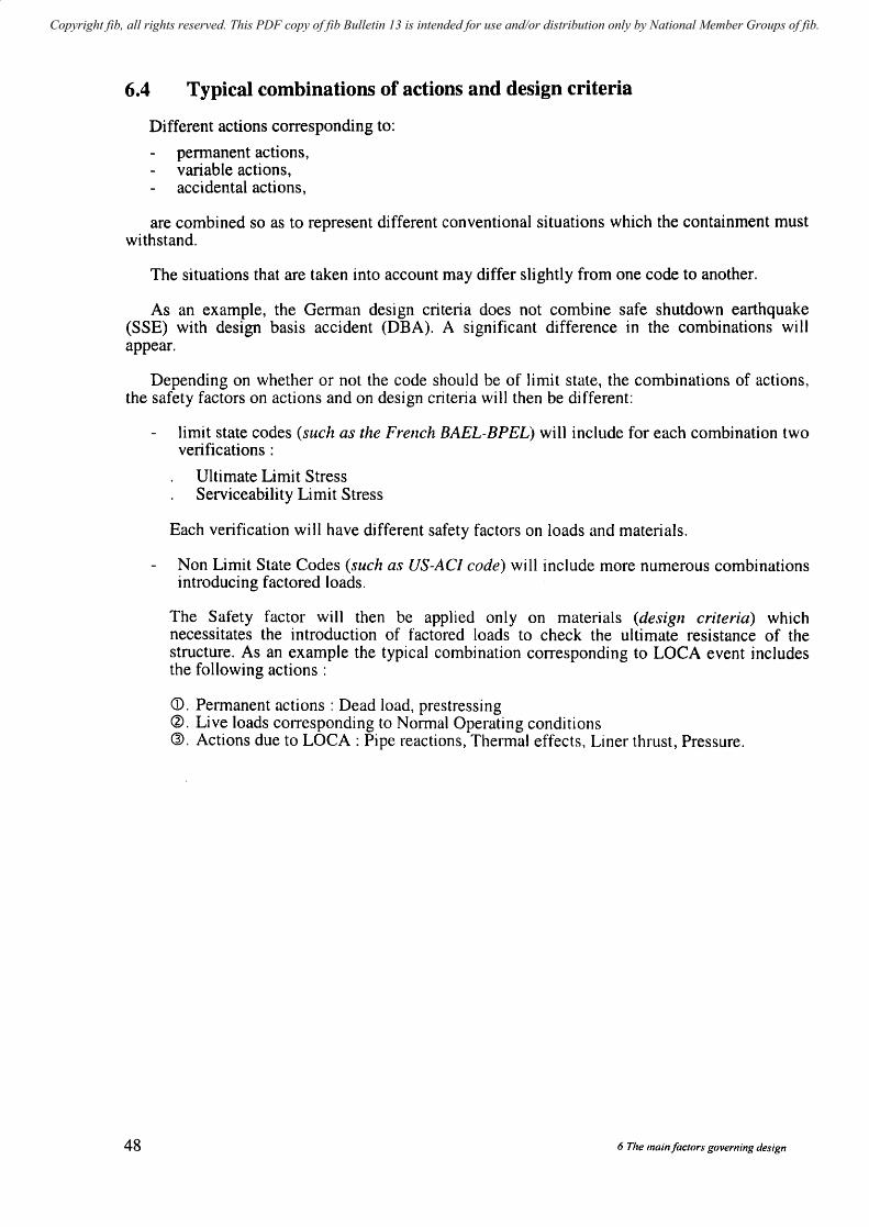
Copyright fib, all rights reserved. This PDF copy of fib Bulletin 13 is intended for use and/or distribution only by National Member Groups of fib.
6.4 Typical combinations of actions and design criteria
Different actions corresponding to:
permanent actions, variable actions, accidental actions,
are combined so as to represent different conventional situations which the containment must withstand.
The situations that are taken into account may differ slightly from one code to another.
As an example, the German design criteria does not combine safe shutdown earthquake (SSE) with design basis accident (DBA). A significant difference in the combinations will appear.
Depending on whether or not the code should be of limit state, the combinations of actions, the safety factors on actions and on design criteria will then be different:
48
limit state codes (such as the French BAEL-BPEL) will include for each combination two verifications :
Ultimate Limit Stress Serviceability Limit Stress
Each verification will have different safety factors on loads and materials.
Non Limit State Codes (such as US-ACI code) will include more numerous combinations introducing factored loads.
The Safety factor will then be applied only on materials (design criteria) which necessitates the introduction of factored loads to check the ultimate resistance of the structure. As an example the typical combination corresponding to LOCA event includes the following actions:
CD. Permanent actions: Dead load, prestressing ~. Live loads corresponding to Normal Operating conditions ®. Actions due to LOCA : Pipe reactions, Thermal effects, Liner thrust, Pressure.
6 The main jac/ors governing design
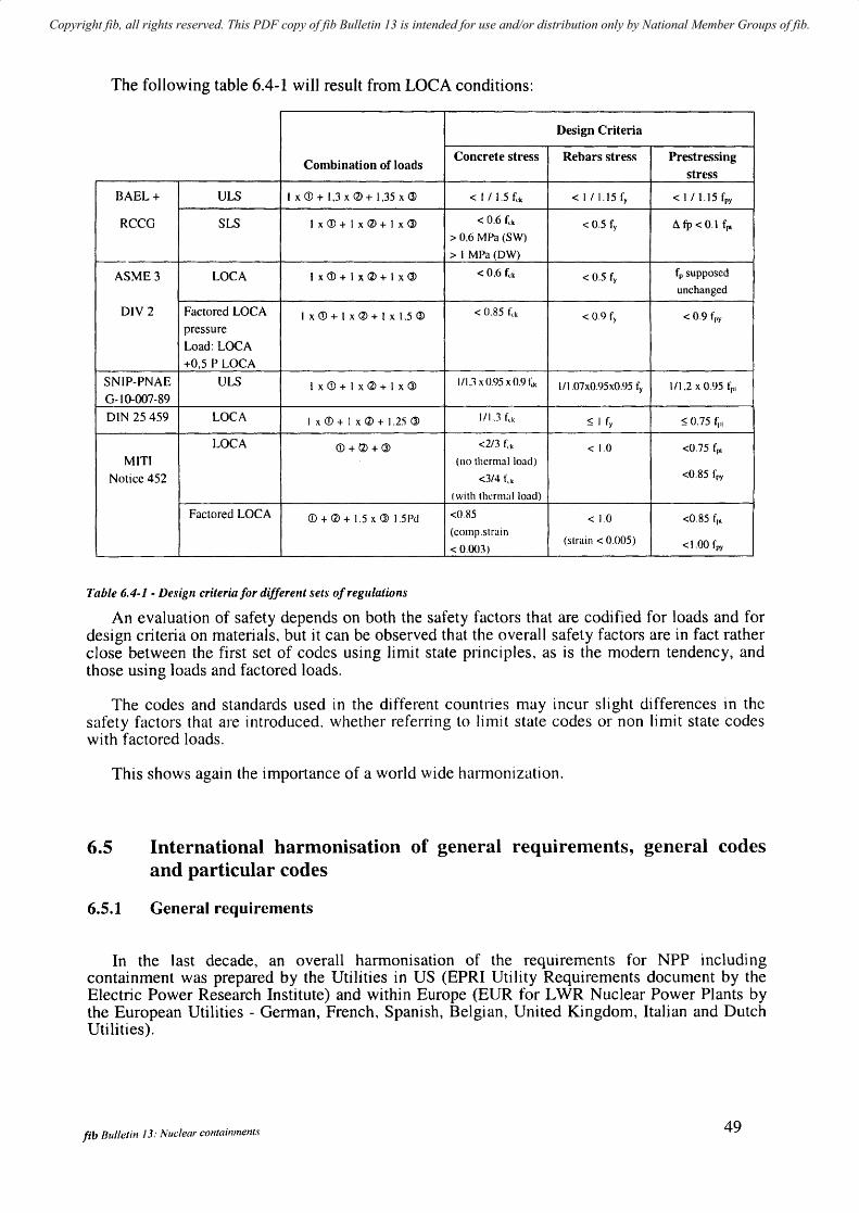
Copyright fib, all rights reserved. This PDF copy of fib Bulletin 13 is intended for use and/or distribution only by National Member Groups of fib.
The following table 6.4-1 will result from LOCA conditions:
Design Criteria
Combination of loads Concrete stress Rebars stress Prestressing
stress
BAEL+ ULS I x CD + 1,3 x <l> + 1,35 x <ll <l/l.5f~k < I 1 1.15 fy < 1/1.15 fpy
RCCG SLS IxCD+lx<l>+lxCi) < 0,6 (t < 0.5 fy ~ fp < 0.1 fpl > 0,6 MPa (SW)
> I MPa (DW)
ASME3 LOCA 1 x<D+ 1 x<l>+ I xCi) < 0.6 fck < 0.5 fy f" supposed
unchanged
DIY 2 Factored LOCA I x CD + I x <l> + 1 x 1.5 0) < 0.85 I~k < 0.9 fy < 0.9 fpy pressure Load: LOCA +0,5 P LOCA
SNIP-PNAE ULS I x<D+ I x<l>+ I x<lJ 1/13 x 0.95 xO.91:X I/l.07xO.95xO.95 fy 111,2 x 0.95 fpl G-I 0-007 -89 DIN 25459 LOCA 1 x CD + 1 x <2) + I .2:') 0> 1/1.3 t~k ::; 1 fy $ 0.75 fp,
LOCA CD+/1)+O> <2/3 f,·k < 1.0 <0.75 fpl MITI (110 thermal load)
Notice 452 <3/4 f.k <0.85 fpy
(with therrnalload)
Factored LOCA CD + <2) + 1.5 x 0> 1.5Pd <085 < 1.0 <0.85 f(ll (cornp .strain
(strain < 0.005) < 0.003) <1.00 fpy
Table 6.4-J - Design criteria for different sets of reg II latio ns
An evaluation of safety depends on both the safety factors that are codified for loads and for design criteria on materials, but it can be observed that the overall safety factors are in fact rather close between the first set of codes using limit state principles, as is the modem tendency, and those using loads and factored loads.
The codes and standards used in the different countries may incur slight differences in the safety factors that are introduced, whether referring to limit state codes or non limit state codes with factored loads.
This shows again the importance of a world wide halmonizution.
6.5 International harmonisation of general requirements, general codes and particular codes
6.5.1 General requirements
In the last decade, an overall harmonisation of the requirements for NPP including containment was prepared by the Utilities in US (EPRI Utility Requirements document by the Electric Power Research Institute) and within Europe (EUR for LWR Nuclear Power Plants by the European Utilities - German, French, Spanish, Belgian, United Kingdom, Italian and Dutch Utilities).
fib Bulletin J 3: Nuclear containments 49
Copyright fib, all rights reserved. This PDF copy of fib Bulletin 13 is intended for use and/or distribution only by National Member Groups of fib.
These documents aim at defining the general principles to be applied but must be complemented by a system of codes and criteria. They include the requirements concerning the containment system in terms of loads and load combinations and of acceptance criteria considering both structural integrity and leak-tightness, but do not define a list of codes and regulations to be applied.
In EUR, the Utilities Requirements define the typical loads to be considered in the containment design including severe accident (Design extension conditions) which have not yet been taken into account in the design of the containments such as:
hydrogen combustion, an accident without active containment heat removal for at least 12 hours, a corium collector in the containment basemat and corium cooling system.
For design basis accidents, structural integrity with a large safety factor is required and the leakage must remain low. For design extension conditions (severe accident), structural integrity with a reduced safety factor is required and a limited increase of leak rate is accepted. The load combination of the design basis accident and the design basis earthquake shall be considered as a design load but only structural integrity is required. The acceptance criteria can be defined depending on the associated code in terms of working stress and/or in terms of load factor (limit state code).
6.5.2 Harmonisation of the general codes
For concrete structures, limit state design was proposed in an international model code (FIPCEB Model Code 1978 and 1990 published in 1992). Fill developments which may also concern containments are underway for new applications and materials (for instance high performance concrete) and special structures.
The Model Code by virtue of its international character is more general than most national codes and provides basic information which is not usually provided in national codes.
In Europe, an important harmonisation is carried out in order to establish a group of standards for the structural and geotechnical design of buildings and civil engineering works (Eurocode for each structural material: concrete structures, steelwork structures, timber structures, etc). For concrete structures Eurocode n02, which follows the international model codes, will be consistent with the other Eurocodes. They should replace the different European national codes from year 2002 onwards. For materials a similar harmonisation is underway (Euronorms) which should replace the present day criteria and specifications for materials.
6.5.3 Particular codes and specific criteria
The objective of particular codes and criteria is to adapt and complement the existing codes to the general requirements set for NPP. The particular codes are either specific chapters of a general code (ACI, DIN) or a separate document consistent with the general code (RCCG).
For the future French and German project EPR, specific design criteria (ETC-CIEPR Technical Code for Civil Works) are written to be consistent with the Eurocodes principles. In the design criteria (ETC-C), the acceptance criteria are given in terms of ultimate limit states when structural integrity is required and in terms of serviceability limit state when Jeakage criteria are required. In addition it should be mentioned that the European Utilities are harmonizing their requirements with respect to the design and layout of future NPPs.
50 6 The main/actors governing design
Copyright fib, all rights reserved. This PDF copy of fib Bulletin 13 is intended for use and/or distribution only by National Member Groups of fib.
6.6 The impact on design of the different factors mentioned previously
6.6.1 General
The complexity of design is related to the number of interfaces between the reactor building within the containment and the adjacent buildings of the Nuclear Island. Justification through often complex computations is necessary for all specific areas such as penetrations, pipe reactions, and equipment loads in numerous cases whether during construction, test, normal operating or accidental situations.
However the overall design performed at the basic design stage, which includes the thickness of concrete, the typical reinforcement and the prestressing pattern will not change significantly at detailed design stages whatever the type of containment: single wall or double wall, with or without a liner. The main parameters, which are all to a certain extent dependent on regulations, are the following:
values of the loads,
the mechanical properties of the materials,
some specific regulatory aspects: combination of loads, regulatory values of paranleters and coefficients, grouted or un bonded prestressing tendons.
The impact of these different parameters are given hereafter in a synthetic approach where only the most significant items are presented.
It is to be remembered that a PWR containlnent is generally much larger than a BWR containment and that the internal pressure is higher than in a PHWR containment. In terms of civil works. the quantities of concrete, reinforcement and prestressing are for that reason larger for a PWR containment than for the other types of reactor and as a consequence the impact on design of the different parameters is particularly significant for PWR containments.
6.6.2 The impact of design loads on structural dimensioning
Table 6.6-1 summarizes schematically the parts of the structure the design of which are or nlay be influenced by some significant loading conditions.
A reminder, as previously described in paragraph 6.3.1, is that differences may appear depending on applied regulations for the definition of the loads as well as their combinations which nlakes comparisions difficult. As an example. the OBE (Operational Basis Earthquake) and 1/2 SSE (half-safe shutdown earthquake) are not directly comparable in terms of safety criteria.
Factored loads not presented in Table 6.6-1 as regulations are assumed to be of limit state category, thus including a factor on loads (ULS):
construction loads: ULS + SLS verification: mainly shrinkage and effect of successive prestressing sequences on reinforcement,
the pressure test (structural integrity test): ULS and SLS verification. Represents the maXilTIUm pressure to which the containment is subjected. Thermal accidental effects are not represented:
1.15 x design pressure if liner present (to represent outwards liner thrust due to temperature), 1.00 x design pressure if no liner present (but additional criteria on membrane compressive stress to avoid leakage).
fib Bulletin 13: lVudeal' confainmen!s 51
Copyright fib, all rights reserved. This PDF copy of fib Bulletin 13 is intended for use and/or distribution only by National Member Groups of fib.
~ Normal operation (NO): ULS and SLS verification
Verification of acceptable stresses in liner due to temperature effects and delayed deformation of concrete,
design of basemat thickness and upper reinforcement (soil reaction).
)0> Operational basis earthquake (OBE+NO) : ULS and SLS verification
Verification that the concrete and liner are not overstressed in compression, particularly in the lower part of containments,
verification of basemat reinforcement,
local reinforcement and design of the junction between mechanical parts and containment. The seismic spectra to which the mechanical parts are submitted strongly influence their dimensioning and the forces at junctions with the containment.
~ Safe shutdown earthquake (SSE + NO) : ULS verification
verification of stresses and reinforcement in basemat and lower part of containment (risk of basemat uplift),
load reinforcement and concept of junctions between mechanical parts and concrete.
)0> Design basis accident (DBA) : ULS and SLS verification
Increment with time of Pressure and Temperature (see fig. 6.6-1) for the lOner or single wall containment,
dimensioning of prestressing under pressure and liner thrust (temperature effects),
dimensioning of reinforcement in standard and local parts such as penetrations or junctions between wall, basemat, dome,
dimensioning of basemat particularly lower and shear reinforcement.
» DBA + SSE
A structural verification (ULS only) is not required by all regulations. This influences vertical prestressing and basemat wall junction as well as local parts (penetrations) and also dimensioning of basemat (possible uplift).
» Hydrogen Combustion (ULS accidental)
This load case is envisaged as a design extension condition for future projects and is a structural verification with a higher peak pressure.
52 6 The main/actors governing design

Copyright fib, all rights reserved. This PDF copy of fib Bulletin 13 is intended for use and/or distribution only by National Member Groups of fib.
~ Accident without heat removal (ULS accidental)
This load case is envisaged as a design extension condition for future projects and is a more severe DBA for Pressure and Temperature.
~ Corium spread (ULS accidental)
Another design extension condition for future projects influences mainly the basemat for thermal effects and the concept of the lower part of the internal structures.
1·--,--·---
O 9 - -- - - J __ -_ __ - ----r- - ---r--J]rll=~~l~~l--~--
--Ple~5llfe ]
. lBO
,
- - Temperalu(t: -~ .. ---.- ---I
0,8 f----- -- - __ .. ....--- - I -f-'-~ . -- r-- '- -~- ----- ---- -1-'
ni 0,7 0..
~ ~ 0,6 -_. -- -. - - -.\ --"--' -.-- ... - . ___ _
VI <1.1
0.. 4J D,S --'- ---- .'. '--" _ .. _- __ . I I /-t--r-- -- --- -- -=~ .. ra 0,4'1--- - ----- -IL..-- ---- ___ -_. ______ . ___ ~ .... ____ "
VV I "~ 1.).,1 I ""
0,3 1------17--------·--1-·-·-· ------- -- . --.---b~",.
V 0.2 . -l/- - -- --- --- -- - ----, . - --- - -- -.
'-. ---"-.---
.............
i' ~
0,1 V~, ___ _ __<---IL-..LJ....L.J..J ______ . __ . _ --.---- .. - -'-- - - ..
10 100 1000 10000
Fig. 6.6-1 - Typical Pressure and Temperature ill case of LOCA versus time (seconds)
fib Bulletin J 3: Nue/car containments
160
HO
120
I,
-1'00
I 80
60
20
o 100000
53
u
COl :; ';;j Qj a. E <1.1 ~
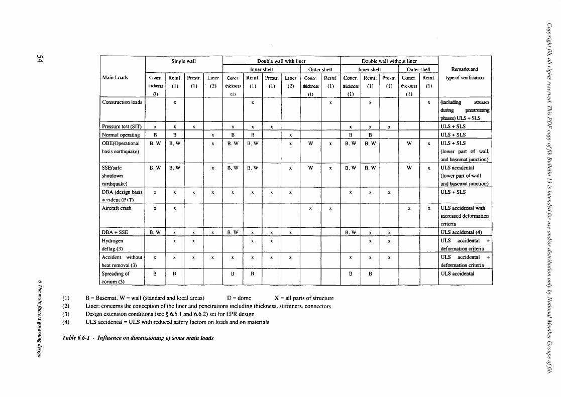
Copyright fib, all rights reserved. This PD
F copy of fib Bulletin 13 is intended for use and/or distribution only by National M
ember G
roups of fib.
Ul ~
0-
~ ~
:: §.
'i:i> ~ ~ ~ ~ ~ ~.
~ ~. :::
Single wall Double wall with liner
Inner shell Outer shell
Main Loads Coocr. Reinf. Prestr. Liner Concr. Reinf. Prestr. Liner ConeI'. Reinf
thickness (1) (1) (2) thickness (1) (I) (2) thickness (I)
(I) (1) (1)
Construction loads x x x
Pressure test (SIT) x x x x x x
Normal operating B B x B B x
OBE(Operational B.W B,W x B.W B.W x W x
basis earthquake)
SSE(safe B.W B,W x B.W B.W x W x
shutdown
earthquake)
DBA (design basis x x x x x x x x
al:l:ident (P+ n Aircraft crash x x x x
DBA + SSE B.W x x x B.W x x x
Hydrogen x x x x
deflag.(3)
Accident without x x x x x x x x
heat removal (3)
Spreading of B B 13 B
corium (3)
( 1) B = Basemat. W = wall (standard and local areas) D = dome X = all parts of structure (2) Liner: concerns the conception of the liner and penetrations including thickness. stiffeners. connectors (3) Design extension conditions (see § 6.5.1 and 6.6.2) set for EPR design (4) ULS accidental = ULS with reduced safety factors on loads and on materials
Table 6.6·1 - Injluellce Oil dimellsiollillg o/some maillioads
Double wall without liner
Inner shell Outer shell Remarks and
Concr. Reinf. Prestr. Concr. Reinf. type of verification
thickness (1 ) (1) thickness (1)
(1) (I)
x x (including stresses
during prestressing
phases) ULS + SLS
x x x ULS + SLS
B B ULS + SLS
B.W B,W W x ULS + SLS
(lower part ,of wall.
and basematjunction)
B,W B,W W x ULS accidental
(lower part of'waU
and basemat junction)
x x x ULS+SLS
x x ULS accidental with
increased deformation
criteria
B.W x x ULS accidental (4)
x x ULS accidental +
deformation criteria
x x x ULS accidental +
deformation criteria
B B ULS accidental
Copyright fib, all rights reserved. This PDF copy of fib Bulletin 13 is intended for use and/or distribution only by National Member Groups of fib.
6.6.3 The impact of design values for mechanical properties of materials on dimensioning
It has been seen previously (§ 6.1. Table 6.1-1) that the design values for mechanical properties of materials depend on regulation and on testing.
Table 6.6-2 summarizes schematically the influence of the design mechanical properties on the dimensioning of the structural components.
~ Concrete
Due to prestressing forces and to thermal effects, the compressive strength of concrete is of course important both for thickness of the structure and for reinforcement determination.
The moduli (instantaneous, or varied for thermal effects for instance) and the values of shrinkage and creep are important parameters for the determi nation of long term prestressing forces and for the determination of the long term stresses in the liner.
~ Rebars
Directly dependent on yield stress of the rebars.
~ Prestressing
The required prestressing forces:
in the short term depend on the ultimate tensile stress (UTS) and yield strength (depending on regulations adopted) and also on the friction factors along the prestressing ducts,
in the long term depend on all other values and in particular relaxation of the steel, as well as shrinkage and creep of the concrete as mentioned previously.
~ Liner
In order to avoid excessive compressive stresses in the liner which may provoke buckling even under normal operating condition, the stress value should preferably remain under yield stress which is an important parameter in the design of the liner. On the other hand a high yield stress causes a high outwards thrust on the concrete in the case of a DBA, which adversely affects reinforcement and prestressing.
~ Geotechnics
The distribution of soil reactions under the base mat depends on the soil moduli. They are very different for a relatively soft foundation and for hard rock. This has a large effect on the base mat (thickness, reinforcement) and on the lower part of the containment.
The soil moduli and damping factors are also important in the determination of the seismic forces to which the reactor building is submitted, which influences the design of the complete containment structure.
fib Bulletin 13: NlIdear cuntainments 55

Copyright fib, all rights reserved. This PDF copy of fib Bulletin 13 is intended for use and/or distribution only by National Member Groups of fib.
Mechanical properties Concrete thickness Reinforcement Prestressine Liner
Concrete Compressive strength x x A Instantaneous modulus x x x Delayed moqulus x x
Shrinkage, creep x x
Rebars Yield stress x
Prestressing Ultimate tensile stress x
Yield stress x
Relaxation value x
Friction factors x uner
Yield stress x x x
Geotechnics Soil moduli B B,W W B.W
Damping characteristics B,W B,W B,W B,W
Nota: B = Basemat W=Wall D=Dome x = all parts of structure A = anchorage zone
Table 6.6-2 - Influence of some design values for mechanical properties of materials on structural dimensioning (outer shell not considered)
6.6.4 Some specific regulatory aspects
~ Load combinations
The safety factors on loads and on stresses in materials which depend on the general and specific codes as indicated in § 6.3.1. may differ slightly from one code to another.
The load combinations themselves may not be quite the saIne (for instance DBA + SSE or not ?).
Some differences may result from the previous remarks in the design of all structural components.
» Regulatory values of some parameters and coefficients
As an example the evaluation of long term prestressing losses depends of course on the conventional test values of shrinkage, creep and relaxation, but also on the regulatory parameters which allow the evaluation of the long term values from the conventional values.
» Grouted or unbonded tendons
Some regulations, ACI for instance, consider the prestressing as either grouted or unbonded, whereas others (BPEL) consider the prestressing solely as grouted for better protection against corrosion.
The reinforcement calculations are quite different in either case, as in a cracked section the prestressing force is constant for an unbonded tendon, but increases for a grouted tendon which is locally over tensioned.
56 6 The main/actors governing design
Copyright fib, all rights reserved. This PDF copy of fib Bulletin 13 is intended for use and/or distribution only by National Member Groups of fib.
7 The construction materials for the containment
7.1 General
As mentioned in chapter 6, the quality of materials used for containment construction whether PWR and VVER, BWR, PHWR, must be strictly established through regulations, qualification tests and certification and checked throughout construction. The main design parameters and corresponding values from regulations and testing are shown in table 6.1-1. The aim of this chapter is to give a broad overview on the definition and qualification for the construction materials themselves.
7.2 Concrete
All components of the concrete are subjected to acceptance tests in relation to:
the quality of the aggregates (hard, homogeneous, clean, not subject to frost, etc.), the grain size distribution, the quality of cement (free from chlorides, from sodium sulfates or carbonates), the quality of admixtures, the properties of mixing water.
Containment structures, being most often prestressed shell structures with numerous penetrations and possibly submitted to high temperature gradients, usually require a high characteristic compressive strength (usually above 35 MPa at 28 days).
On the other hand, sufficient workability and maximum aggregate dimensions are specified considering the dense structural arrangements and conditions for workmanship.
The composition tolerances of each component of the batch of concrete must be closely controlled and is as a rule in the region of 5 % by weight for each category of aggregate and 1 % for water and cement. The capacity of the constructor to respect all specifications and the quality and precision of his batching plant are controlled by acceptance tests and checked throughout construction. Segregation must be avoided during transport or placing and adequate vibration must be provided especially when dense reinforcement or penetrations make placing difficult.
A compact and leaktight concrete is advisable in any case, but for a double contaimnent with no liner, the imperviousness of the inner shell concrete is particularly necessary, which requires special testing of the concrete for leaktightness.
As mentioned in § 6.6.3, the long-term behaviour of the concrete must be ensured by adequate testing before construction as well for long term phenomena (prediction of creep and shrinkage, heat of hydration) as for detrimental effects (such as risk of alkali reaction).
The pressure test performed at the end of the containment construction, known as the Structural Integrity Test (SIT), then gives an excellent indication of the quality of the construction as well for the compactness of the concrete itself as for possible leakages at lifts or penetrations.
fib Bulletin J 3: lVl/c:lear cOflfainments 57

Copyright fib, all rights reserved. This PDF copy of fib Bulletin 13 is intended for use and/or distribution only by National Member Groups of fib.
Special testing for frost resistance (such as freeze and thaw tests) and a concrete of excellent compaction is also required in special climatic conditions. If concreting is necessary at freezing temperatures, special construction arrangements are taken such as heating of water and aggregates and insulation after pouring the concrete.
Recent improvements in concrete mixes known as high performance concrete are presented in chapter 9.3.
7.3 The steel liner and penetrations
The steel liner ensures leak tightness in standard areas and at penetration junctions but does not contribute to the strength of the structure except for some special design loads (external impacts). The stresses in the liner are calculated by considering the strain compatibility of deformations between liner and concrete. As a consequence the stresses in the liner and the incursion into the plastic phase is dependent on concrete deformation including various deformations and temperature conditions in normal and accidental situations. As a rule it is considered preferable to avoid plasticity during normal operating conditions and for this reason a sufficient minimum yield stress is advised for instance fy> 250 MPa.
Stiffeners are provided and are particularly necessary for ensuring stiffness during construction, before and during concreting.
Studs are provided to avoid buckling and designed to prevent progressive rupture in case of a local rupture.
The grade of steel used for the liner (6 to 10 mm thick) as well as for plates, stiffeners, penetrations and hatches (from 12 to 80 mm thick) is usually in the region of fu = 420 MPa.
The plates of 16 to 20 mm thickness are.anchored by connectors to the concrete. The weldability is checked by tensile and bending ~ests. The penetrations and hatches are usua1Jy welded to the liner which is locally thickened (for instance to 10 mm) before concreting.
, ., Stresses in the concrete of prestressed containments are high around penetrations and
particularly around large penetrations. The penetration is then designed with a sufficient thickness and with sufficient reinforcement around the penetration to relieve the stresses in the concrete to acceptable values. Thickening of the concrete shell in the area of hatches may nevertheless be necessary.
In the case of containments with no steel liner, provisions are made for easy welding of the steel penetration tube to the penetration casing embedded in the concrete and preferably not protruding. On the main penetrations and hatches, radial discs are welded round the penetrations so as to improve leak tightness.
Present developments and research work on composite liners are presented in chapter 9.3.
7.4 Reinforcing steel bars
The reinforcing steel is mainly of deformed bar type with a yield stress fy in the region of 400 MPa.
In Europe the diameter of bars is usually limited to 32 mm and exceptionally 40 mm. In the US, the diameters reach 56 mm. This requires joining the bars by means of sleeves, the use of which is exceptional in Europe.
58 7 The construction materials for the containment
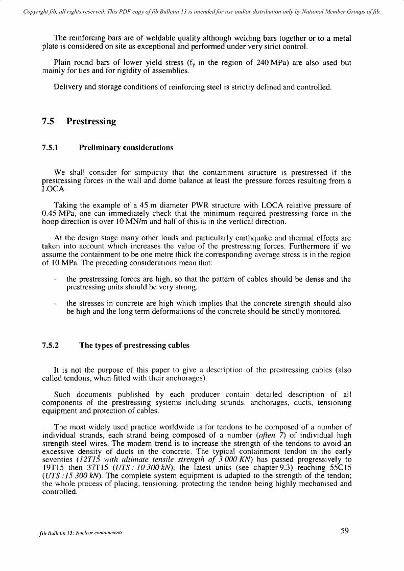
Copyright fib, all rights reserved. This PDF copy of fib Bulletin 13 is intended for use and/or distribution only by National Member Groups of fib.
The reinforcing bars are of weldable quality although welding bars together or to a metal plate is considered on site as exceptional and performed under very strict control.
Plain round bars of lower yield stress (fy in the region of 240 MPa) are also used but mainly for ties and for rigidity of assemblies.
Delivery and storage conditions of reinforcing steel is strictly defined and controlled.
7.5 Prestressing
7.5.1 Preliminary considerations
We shall consider for simplicity that the containment structure is prestressed if the prestressing forces in the wall and dome balance at least the pressure forces resulting from a LOCA.
Taking the example of a 45 m diameter P\VR structure with LOCA relative pressure of 0.45 MPa, one can immediately check that the minimum required prestressing force in the hoop direction is over 10 MN/m and half of this is in the vertical direction.
At the design stage many other loads and particularly earthquake and thermal effects are taken into account which increases the value of the prestressing forces. Furthermore if we assume the containment to be one metre thick the corresponding average stress is in the region of 10 MPa. The preceding considerations mean that:
the prestressing forces are high, so that the pattern of cables should be dense and the prestressing units should be very strong,
the stresses in concrete are high which implies that the concrete strength should also be high and the long term deformations of the concrete should be strictly monitored.
7.5.2 The types of prestressing cables
It is not the purpose of this paper to gi ve a description of the prestressing cables (also called tendons, when fitted with their anchorages).
Such documents published by each producer contain detailed description of all components of the prestressing systems including strands, anchorages, ducts, tensioning equipment and protection of cables.
The most widely used practice worldwide is for tendons to be composed of a number of individual strands, each strand being composed of a number (often 7) of individual high strength steel wires. The modern trend is to increase the strength of the tendons to avoid an excessive density of ducts in the concrete. The typical containment tendon in the early seventies (12T15 with ultimate tensile strength of 3 000 KN) has passed progressively to 19T15 then 37T15 (UTS,' 10300 kN), the latest units (see chapter 9.3) reaching 55C15 (UTS :15 300 kN). The complete system equipment is adapted to the strength of the tendon; the whole process of placing, tensioning, protecting the tendon being highly mechanised and controlled.
fib Bulletin J 3: Nuclear containments 59
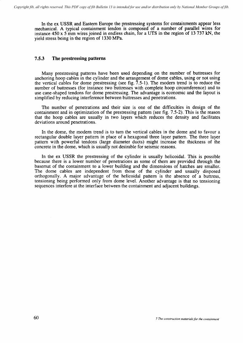
Copyright fib, all rights reserved. This PDF copy of fib Bulletin 13 is intended for use and/or distribution only by National Member Groups of fib.
In the ex USSR and Eastern Europe the prestressing systems for containments appear less mechanical. A typical containment tendon is composed of a number of parallel wires for instance 450 x 5 mm wires joined in endless chain, for a UTS in the region of 13 737 kN, the yield stress being in the region of 1330 MPa.
7.5.3 The prestressing patterns
Many prestressing patterns have been used depending on the number of buttresses for anchoring hoop cables in the cylinder and the arrangement of dome cables, using or not using the vertical cables for dome prestressing (see fig. 7.5-1). The modern trend is to reduce the number of buttresses (for instance two buttresses with complete hoop circumference) and to use cane-shaped tendons for dome prestressing. The advantage is economic and the layout is simplified by reducing interference between buttresses and penetrations.
The number of penetrations and their size is one of the difficulties in design of the containment and in optimization of the prestressing pattern (see fig. 7.5-2). This is the reason that the hoop cables are usually in two layers which reduces the density and facilitates deviations around penetrations.
In the dome, the modern trend is to turn the vertical cables in the dome and to favour a rectangular double layer pattern in place of a hexagonal three layer pattern. The three layer pattern with powerful tendons (large diameter ducts) might increase the thickness of the concrete in the dome, which is usually not desirable for seismic reasons.
In the ex USSR the prestressing of the cylinder is usually helicoidal. This is possible because there is a lower number of penetrations as some of them are provided through the basemat of the containment to a lower building and the dimensions of hatches are smaller. The dome cables are independent from those of the cylinder and usually disposed orthogonally. A major advantage of the helicoidal pattern is the absence of a buttress, tensioning being performed only from dome level. Another advantage is that no tensioning sequences interfere at the interface between the containment and adjacent buildings.
60 7 The consTruction materials for the containment
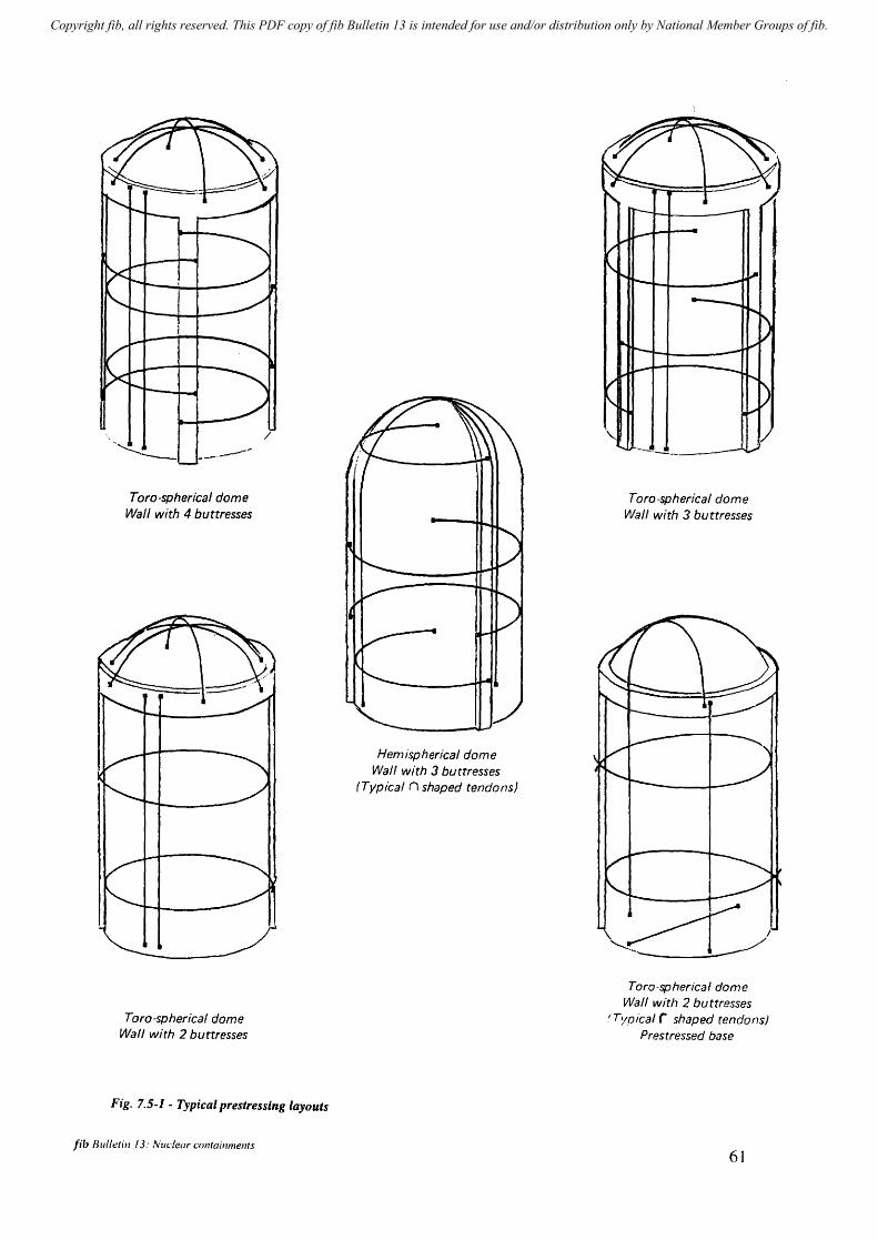
Copyright fib, all rights reserved. This PDF copy of fib Bulletin 13 is intended for use and/or distribution only by National Member Groups of fib.
Taro-spherical dome Wall with 4 buttresses
Taro-spherical dome Wall with 2 buttresses
/
Fig. 7.5-1 - Typical prestressing layouts
fib Blilletin J 3: lv'lIdear containments
Hemispherical dome Wall with 3 buttresses
(Typical n shaped tendons)
Toro-spherical dome Wall with 3 buttresses
Taro-spherical dome Wall with 2 buttresses
I Tyoical r shaped tendons) Prestressed base
61
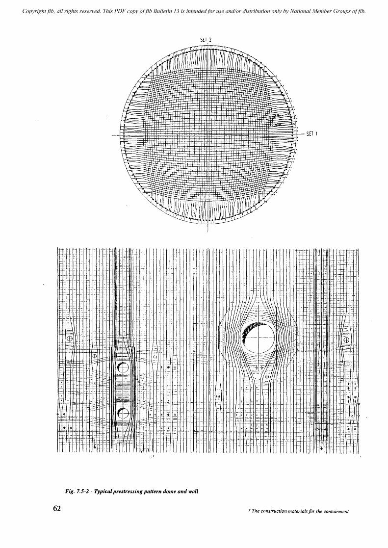
Copyright fib, all rights reserved. This PDF copy of fib Bulletin 13 is intended for use and/or distribution only by National Member Groups of fib.
- ,. - --- - .- .. - -.-
- - - - - - + + -.. - • - ••
. - - - -- -
. . - - ~
- - - ~ - -'
"I
TIll I
SCI 'L I
"I". _.
Fig. 7.5-2 - Typical prestressing pattern dome and wall
62
SET 1
II
.... .. + • - - - -~
+ ..... -- -:: - == ~.=-: .- - _." - -
7 The construction materials/or the containment
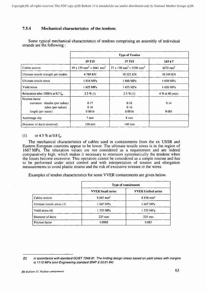
Copyright fib, all rights reserved. This PDF copy of fib Bulletin 13 is intended for use and/or distribution only by National Member Groups of fib.
7.5.4 Mechanical characteristics of the tendons
Some typical mechanical characteristics of tendons comprising an assembly of individual strands are the following:
Type of Tendon
19TIS 37 TIS 163 q,7
Cables section 19 x 139 mm2 = 2641 mm2 37 x 150 mm2 = 5550 mm2 6272 mm2
Ultimate tensile strength per tendon 4789 KN 10323 KN 10 349 KN
Ultimate tensile stress 1 814 MPa 1860 MPa 1 650 MPa
Yield stress 1625 MPa 1655 MPa J 450 MPa
Relaxation after 1000 h at 0,7 fpl 2.5 % (1) 2.5 % (1) 4 % at 40 years
Friction factor
curvature: sheaths (per radian) 0.17 0.18 0.14
tubes (per radian) 0.16 0.16
length (per meter) 0.0016 0.0016 0.001
Anchorage slip 7mm 8 mm
Diameler or ducts (external) 100mm 140mm
(1) or 4.5 % at 0.8 fpt
The mechanical characteristics of cables used in containments from the ex USSR and Eastern European countries appear to be lower. The ultimate tensile stress is in the region of 1667 MPa. The relaxation values are not considered as a requirement and are indeed comparatively high, which makes it necessary to retension systematically the tendons when the losses become excessive. This operation cannot be considered as a simple routine and has to be perfOtmed under strict control and with interpretation of tension and elongation measurements to avoid plastic strains and the risk of excessive stresses in the wires.
Examples of tendon characteristics for some VVER containments are gi ven below.
Type of containment
VVER Small series VVER Unified series
Cables section 8663 mmz 8830 mm2
Ultimate tensile stress (3) 1 667 MPa 1667 MPa
Yield stress (4) 1335 MPa 1335 MPa
Diameter of ducts 225 mm 225mm
Friction factor 0.0985 0.085
(3) in accordance with standard GOST 7348-81. The limiting design stress based on yield stress with margins is 1110 MPa (civil Engineering standard SNIP 2.03.01.84)
fib Bulletin 13: Nuclear containments 63
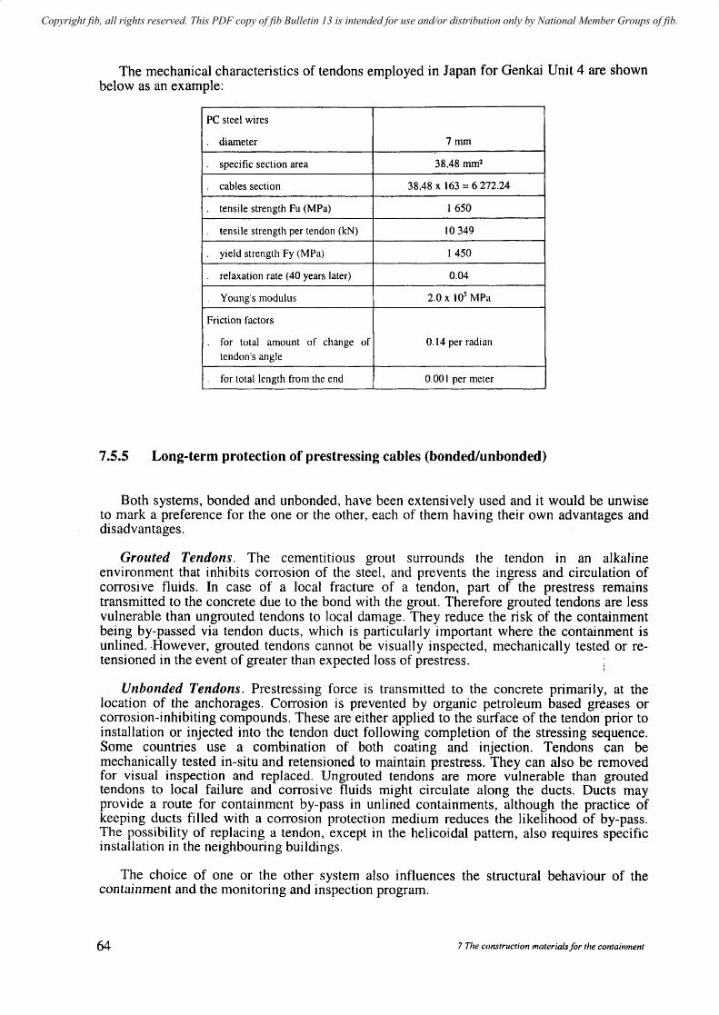
Copyright fib, all rights reserved. This PDF copy of fib Bulletin 13 is intended for use and/or distribution only by National Member Groups of fib.
The mechanical characteristics of tendons employed in Japan for Genkai Unit 4 are shown below as an example:
PC steel wires
diameter 7 mrn
specific section area 38,48 mrnl
cables section 38,48 x 163 = 6272.24
tensile strength Fu (MPa) 1650
tensile strength per tendon (kN) to 349
yield strength Fy (MPa) 1 450
relaxation rate (40 years later) 0.04
Young's modulus 2.0 x 10⁵ MPa
Friction factors
for total amount of change of 0.14 per radian
tendon's angle
for total length from the end 0.001 per meter
7.5.5 Long-term protection of prestressing cables (bondedlunbonded)
Both systems, bonded and unbonded, have been extensively used and it would be unwise to mark a preference for the one or the other, each of them having their own advantages and disadvantages.
Grouted Tendons. The cementitious grout surrounds the tendon in an alkaline environment that inhibits corrosion of the steel, and prevents the ingress and circulation of corrosi ve fluids. In case of a local fracture of a tendon, part of the prestress remains transmitted to the concrete due to the bond with the grout. Therefore grouted tendons are less vulnerable than ungrouted tendons to local damage. They reduce the risk of the containment being by-passed via tendon ducts, which is particularly important where the containment is unlined .. However, grouted tendons cannot be visually inspected, mechanically tested or retensioned in the event of greater than expected loss of prestress.
Unbonded Tendons. Prestressing force is transmitted to the concrete primarily, at the location of the anchorages. Corrosion is prevented by organic petroleum based greases or corrosion-inhibiting compounds. These are either applied to the surface of the tendon prior to installation or injected into the tendon duct following completion of the stressing sequence. Some countries use a combination of both coating and injection. Tendons can be mechanically tested in-situ and retensioned to maintain prestress. They can also be removed for visual inspection and replaced. Ungrouted tendons are more vulnerable than grouted tendons to local failure and corrosive fluids might circulate along the ducts. Ducts may provide a route for containment by-pass in unlined containments, although the practice of keeping ducts filled with a corrosion protection medium reduces the likelihood of by-pass. The possibility of replacing a tendon, except in the helicoidal pattern, also requires specific installation in the neighbouring buildings.
The choice of one or the other system also influences the structural behaviour of the containment and the monitoring and inspection program.
64 7 The construction materials/or the containment

Copyright fib, all rights reserved. This PDF copy of fib Bulletin 13 is intended for use and/or distribution only by National Member Groups of fib.
With regard to structural behaviour, grouted tendons can take variations of stress along their length by bond stresses between the steel surface and the grout. Thus the tendons contribute to the crack distribution when the internal overpressure has exceeded the value corresponding to the tensile strain capacity of the concrete. In such a case the crack widths are smaller than if the tendons were ungrouted. The probability of leakage is smaller if the crack widths are smaller. When designing for certain crack width limits, both prestressing steel and reinforcement steel are considered if the prestressing tendons are grouted, while only the reinforcement steel is considered if the prestressing tendons are ungrouted. Ungrouted tendons must be accordingly supplemented with an extra amount of reinforcing steel, to attain the same safety level against excessive crack widths.
Another structural aspect is that the grouted tendons are not entirely dependent on the end anchorages. Thus, if the end anchorages are damaged, for instance by fire, the prestressing force is still maintained along the effective length of the tendon. The same applies in the case of a local defect on the tendon, e.g., due to the impact of a missile or localised corrosion.
With regard to the inspection program, unbonded tendons undergo a systematic observation of some cables to measure their tension and observe the state of the steel and protection grease or wax. This is of course not possible with grouted tendons for which the prestressing losses with time are evaluated through the overall monitoring system of the strains in the concrete. A limited number of unbonded tendons are sometimes added to check the variation of tension in those tendons and particularly to verify the relaxation properties which are not directly accessible through the overall monitoring system.
Table 7.5-1 hereafter gives details of the types of prestressing and protection of steel normally used for recent plants in different countries.
One can observe that in the USA, Japan and the ex USSR, tendons are usually unbonded whereas in western Europe except Great Britain and also in a number of other countries they are grouted.
In countries from the ex USSR the very high relaxation observed in the prestressing steel makes it necessary that the tendons be ungrouted so that they can be retensioned periodically whereas in US and Japan the measurement of stresses in a selection of tendons is considered adequate as a control test. The tendons in ex USSR containments are unbonded but usually not grease protected although they are grease coated before installation.
In conclusion, one would consider that the choice of grouted tendons is excellent if the quality of the steel and concrete allow for low long term deformations (relaxation, creep) and if sufficient care and control is taken of the quality of the grouting so as to ensure effective long term protection.
The choice of unbonded tendons gives the advantage that the residual tensile force in the tendon may be measured directly under the surveillance program but with the disadvantage that the tendon ducts do not benefit from the excellent permanent protection provided by cementitious grout. It is for this reason that a large amount of effort has been expended on developing the long term performance of greases and duct fillers to ensure the effective protection of the steel [L.M. Smith (1997)]. Due to the inherent uncertainties and dangers during tendon stressing operations, extensive and frequent retensioning should be avoided.
fib Bulletin J 3: Nuclear containments 65
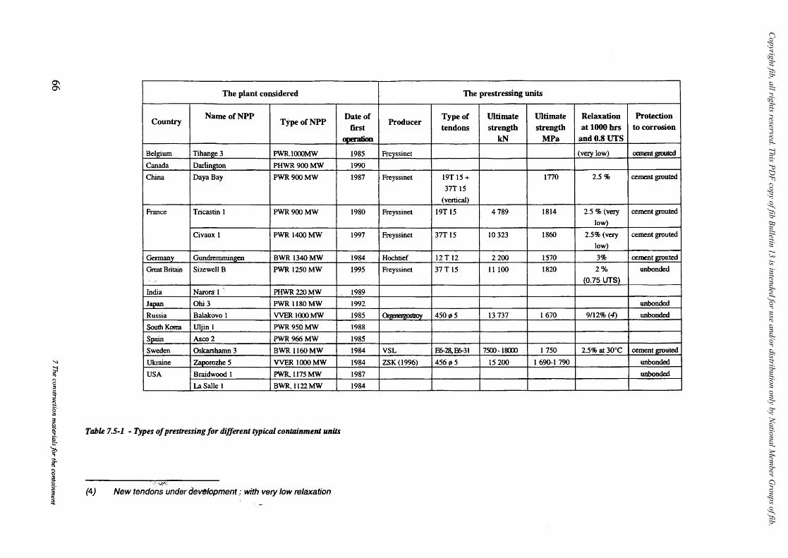
Copyright fib, all rights reserved. This PD
F copy of fib Bulletin 13 is intended for use and/or distribution only by National M
ember G
roups of fib.
0\ 0\
'I
~ ~ () o ::l :., ~
fi 0' ::s :! Q
Country
Belgium
Canada
China
France
Germany_
Great Britain , -
India
Japan
Russia
South Korea
Spain
Sweden
Ukraine
USA
The plant considered
NameofNPP TypeofNPP
Tihange 3 PWR.l000MW
Darlington PHWR900MW
DayaBay PWR900MW
Tricastin 1 PWR 900 MW
Civaux 1 PWR 1400MW
Gundremmingen BWR 1340MW
Sizewell B PWR I250MW
Naronr 1 " PHWR220MW
Ohi3 PWR 1180MW
Balakovo 1 VVER 1<XX> MW
Uljin 1 PWR 950 MW
Asco2 PWR966MW
Oskarshamn 3 BWR 1160MW
Za~rozhe5 VVER lOOOMW
Braidwood I PWR1l75MW
LaSalle I BWR, 1122MW
~ Table 7.5-1 - Types of prestressing for different typical contoinment unUs 5' 1:;-
~ ., ~ g § :1" :1 !1:l
~
~.: :..'"'Y::
(4) New tendons under ae~opment ,: with vel}' low relaxation
Date of first
1985
1990
1987
1980
1997
1984
1995
1989
1992
1985
1988
1985
1984
1984
1987
1984
The prestressing units
Type of Ultimate Ultimate Relaxation Protection Producer
tendons strength strength at 1000 hrs to corrosion kN MPa and 0.8 UTS
Freyssinet (very low) cement grouted !
Freyssinet 19T 15 + 1770 2.5% cement grouted
37T 15
(vertical)
Freyssinet 19T 15 4789 1814 2.S % (very cement grouted
low)
Freyssinet 37T 15 10323 1860 2.5% (very cement grouted
low)
Hochtief 12 T 12 2200 1570 3% cement grouted
Freyssinet 37 T 15 II 100 1820 2% unbonded
(0.75 UTS)
unbonded
450~5 13 737 1670 9112% (4) unbonded
VSL E6-28, E6-31 7SOO-1&xx> 1750 2.5% at 30°C cement grouted
ZSK(1996) 456~S IS 200 1690-1 790 unbonded
unbonded

Copyright fib, all rights reserved. This PDF copy of fib Bulletin 13 is intended for use and/or distribution only by National Member Groups of fib.
8 Construction methods for the containment
8.1 General Because the containment plays an important part in the safety of the plant, a high quality
of construction Inust be guaranteed and very stringent construction rules met.
The quality assurance program of the contractor includes:
a cOlnplete description of the contractor's resources and organization as well as the organization of controls he intends to perform,
a complete set of specifications, acceptance tests and procedures for all types of works: excavations, materials for concrete and concreting, shuttering, rebars, liner, welding, prestressing, tolerances, etc. This must also include procedures for dealing with non compliances.
All documents are submitted for approval to the engineer/architect who exerts strict control over the construction. Recording and reporting to the regulatory authorities is required.
The construction operations and tnethods depend on the contractors practice but also on the type of containment: double or single wall, liner or no liner, type of prestressing, number of penetrations, size of containnlent, etc.
8.2 The basemat and foundations
8.2.1 Type of basemat
Depending on the type of plant the basemat of the containment may either be a single slab resting directly on the foundation (most PWR and PHWR); or a sandwich type slab with an upper and lower slab (BWR) ; or rest on another low building connected to the rest of the nuclear island (VVER).
Where differential settlelnents due to foundation characteristics are expected or additional stability and reduction of displacements between adjacent buildings is required during an earthquake, a comInon basemat for Reactor building and adjacent buildings can be provided.
8.2.2 Foundation
If the bearing capacity of foundation soil is insufficient (average vertical stress under basemat around 0.5 MPa) or settlement excessive, inlprovement of soil characteristics is required: soil substitution or stabilization, grouting, construction of an underlying basemat or even piling (for example, Doel or Tihange in Belgium). In order to avoid corrosion of the dense basemat rebars at soil level, an impervious layer of material is placed under the basemat particularly when the table water level is above the foundation level of the structures.
8.2.3 Construction stages of the basemat
The simple slab is the most usual type of basemat, the tendency being to avoid a very thin baselnat even if it is structurally possible (rock foundation) for reasons of corium spread under accident conditions.
fib Bulletin /3: Nuclear containments 67
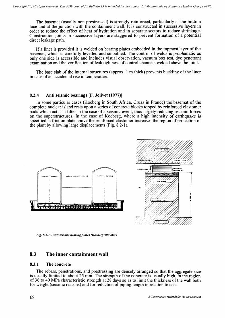
Copyright fib, all rights reserved. This PDF copy of fib Bulletin 13 is intended for use and/or distribution only by National Member Groups of fib.
The basemat (usually non prestressed) is strongly reinforced, particularly at the bottom· face and at the junction with the containment wall. It is constructed in successive layers in order to reduce the effect of heat of hydration and in separate sectors to reduce shrinkage. Construction joints in successive layers are staggered to prevent formation of a potential direct leakage path.
If a liner is provided it is welded on bearing plates embedded in the topmost layer of the basemat, which is carefully levelled and smoothed. The control of welds is problematic as only one side is accessible and includes visual observation, vacuum box test, dye penetrant examination and the verification of leak tightness of control channels welded above the joint.
The base slab of the internal structures (approx. 1 m thick) prevents buckling of the liner in case of an accidental rise in temperature.
8.2.4 Anti seismic bearings [F. Jolivet (1977)]
In some particular cases (Koeberg in South Africa, Cruas in France) the basemat of the complete nuclear island rests upon a series of concrete blocks topped by reinforced elastomer pads which act as a filter in the case of a seismic event, thus largely reducing seismic forces on the superstructures. In the case of Koeberg, where a high intensity of earthquake is specified, a friction plate above the reinforced elastomer increases the region of protection of the plant by allowing large displacements (Fig. 8.2-1).
Fig. 8.2-1 - Anti seismic bearing plates (Koeberg 900 MW)
8.3 The inner containment wall
8.3.1 The concrete
The rebars, penetrations, and prestressing are densely arranged so that the aggregate size is usually limited to about 25 mm. The strength of the concrete is usually high, in the region of 36 to 40 MPa characteristic strength at 28 days so as to limit the thickness of the wall both for weight (seismic reasons) and for reduction of piping length in relation to cost.
68 8 Construction methods/or the containment

Copyright fib, all rights reserved. This PDF copy of fib Bulletin 13 is intended for use and/or distribution only by National Member Groups of fib.
A typical mix would contain 350 kg/m3 of cement and have a water/cement ratio in the region of 0.5.
If no liner is provided, the imperviousness of the concrete has to be more strictly controlled which requires that special attention is paid to the occurrence of cracks and to the surface quality of the concrete lifts.
As mentioned in 7.2 construction must be performed and controlled in accordance with all specifications and tolerances.
8.3.2 The rebars
The rebars, normally of the deformed type are usually assembled in prefabricated panels to be fixed in place at the inner and outer face of the containment.
In very densely reinforced parts, for instance at the basemat-wall junction, mechanical splices may be used.
Welding of bars is only used in exceptional cases, when absolutely necessary, and under very strict conditions.
8.3.3 The steel-liner (when present)
As JTIentioned in chapter 7 the steel liner, usually 6 ITIITI thick, is most often a surface liner coating the inside face of the containment wall (see Fig. 8.3-1 and Fig. 8.3-2). A sufficient minimum yield stress (usually around 255 MPa) limits the risk of buckling and a good weldability is necessary. The steel liner is erected prior to concreting in the form of prefabricated panels welded to each other so as to form complete rings, several metres in height (for instance 4 m). Considering the stringent tolerances on the radius of the circular shape (± 5 cm), (for a diameter in the region of 40 m for a PWR), and the fact that the liner will be used as formwork for the concrete lifts, it is necessary for rigidity to provide stiffeners (angle bars) in the horizontal and vertical direction (for instance 120 x 80 x 10 mm) which are finally embedded in the concrete. Connector studs forn1ing a square grid ensure the connection between the liner and the concrete to prevent buckling due to long term deformation of the concrete and any rise of temperature due to accidental events.
The different penetrations, including very large penetrations such as the equipment hatch which may reach 8 m in diameter, personnel air locks, transfer tubes, batteries of small penetrations and also the brackets of the polar crane are welded on to the liner before erection. The liner stiffeners and anchor bolts to be embedded in the concrete are modified in these areas. The welds are 100 % tested by visual inspection, dye penetrant, vacuum box and partly by X-ray n1ethods and ultrasonic examination.
An alternative to the surface steel liner is a liner embedded in the concrete. This method was mainly used in Scandinavia (Sweden and Finland). The liner is then protected against buckling due to an accidental rise in temperature by the concrete protection on the inner face. Reservations in the concrete are provided just large enough for installation of ducts and their welding to the liner.
In Russia high vertical panels including the liner, reinforcement and prestressing ducts have been used.
In Japan the large block construction method has been used successfully (Kashiwazahi unit 7 RCCV). The tnodules weighing up to 460 tons are lifted with a large 925 ton capacity crawler crane.
fib Bulletin 13: Nuclear containments 69

Copyright fib, all rights reserved. This PDF copy of fib Bulletin 13 is intended for use and/or distribution only by National Member Groups of fib.
Fig. 8.3-1 - Surface steel/iner
Fig. 8.3-2 - Details of duct.'!, rebars and steel/iller
70 8 Construction methods for the containment

Copyright fib, all rights reserved. This PDF copy of fib Bulletin 13 is intended for use and/or distribution only by National Member Groups of fib.
8.3.4 The casting of the concrete
The casting method depends on the existence or not of a liner.
> Surface steel liner
The liner is usually erected much higher than the concrete so that the concrete is usually poured from the outside of the containment. The outer formwork is self-supporting and independent from the liner.
The concrete of each lift (as a rule in the region of2 to 2.5 m high) is poured in several (4 or 5) continuous layers (for instance 50 cm high) thus avoiding excessive pressure which might deform the steel liner. The time between pouring of successive layers is usually determined so as to allow vibration to bond the concrete of the new layer with that of the underlying layer and ensure continuity.
Special care is taken in areas difficult to reach or congested by reinforcing steel and penetrations, for instance under equipment or personnel hatch.
> Embedded steel liner
For Scandinavian applications an embedded liner has been provided for different applications (BWR and PWR containments). The steel liner is erected by using the same method as for an oil storage tank, i.e. steel plate rings are welded at ground level and added to the already completed part of the cylinder, which is successively jacked up. The inner and outer parts of the wall are then cast in two separate slipfonn operations. The prestressing cables or the cable ducts are tTIounted before casting. The SaIne method has also been used with the steel cylinder erected in a conventional way froln the ground level without jacking.
In Oskarshamn 3 the entire asseJTIbly of liner, rebars, ducts, etc. was prefabricated away frOln its final position to which the assembly was skidded.
> No steel liner
This type of containment which assumes a double wall containlnent has been extensively used in France for the 1 300 MW and 1 400 MW PWR series since 1977 (24 units operating) and also in India for the PHWR type containments (8 units).
The quality of concrete and particularly its degree of iJnperviousness is important to limit the volulne of air or steam to be collected in the annular space during an accident. The pressure test which verifies after construction that the leakage through the inner containment meets the regulatory requirements is also an excellent test of the quality of the construction.
The concrete is usually pumped from a mast erected in the centre of the reactor building (see Fig. 8.3-3).
The form\vork annular shuttering is bolted on the previous lift (see Fig. 8.3-4) and a working platform bears on each face of the containment enabling access and the work to be performed and controlled from both sides. The two sides of the shuttering are not connected to avoid possible leakages along the bolts. In France the climbing shuttering technique is preferred to the slipform as it allows Inore facility for placing and controlling the works and more flexibility in case of any incident.
The lifts usually in the region of 2 to 2,5 m high are poured in successive layers (for instance 50 cm thick).
Control tubes are placed at the surface of each lift enabling control of leak tightness and if necessary improvement by grouting.
fib Bulletin 13: Nue/ear containments 71

Copyright fib, all rights reserved. This PDF copy of fib Bulletin 13 is intended for use and/or distribution only by National Member Groups of fib.
72
Fig. 8.3-3 - Concreting mast/or containlllellt alld internal structures (110 liner)
HYOfIAULIC JACKS
EXTERtOR
I 0 JACIIIHC ROO$
MANOfIll MOlDS HOLE rOlit PlACING or vtRTICAl CAkU
lJ INTtRIOR
Fig. 8.3-4 - Slip/orm shutterillg - Gentilly, Callada
8 Construction methods/or the containment

Copyright fib, all rights reserved. This PDF copy of fib Bulletin 13 is intended for use and/or distribution only by National Member Groups of fib.
8.4 The inner containment dome
8.4.1 With a liner
For a PWR with a dome roof, the liner is usually assembled on the ground and hoisted (sOJl1etilnes in two adequately stiffened halves for reasons of weight), into position. This operation only takes place after erecting the polar crane. The two halves are then welded together and to the existing wall liner.
The steel liner is norn1ally used as formwork. A typical concreting sequence is shown in Figure 8.4-1 for a French containment. A thin (20 cm) layer corresponding to the load bearing capacity of the steel liner is first concreted and prestressing tendons and rebars are then installed. After the concrete has gained sufficient strength the relnaining portion of the shell is cast with construction joints as indicated in Figure 8.4-1.
A similar idea has been applied to the Scandinavian containn1ents with a roof slab and an elnbedded liner. The formwork is designed only for the concrete on the inside of the liner. When the concrete has hardened the steel liner is mounted and the inside concrete carries the load when the remaining concrete above the liner is cast. Grouting is done under the steel liner.
8.4.2 \Vithout a liner
Different techniques have been used. One of them consists of the erection at the dome apex of a concrete central block resting on the polar crane. Prefabricated thin concrete segments (see fig. 8.4-2) bridging the topmost lift of the wall and the central block are erected forming an umbrella like shuttering on which a continuous thin layer of concrete is poured. The p'lacing of rebars, prestressing tendons and pouring of concrete is then performed in a similar way to a dome with a steel liner.
The concrete segments and first layer of concrete are incorporated and linked by stirrups to the prestressed concrete above.
8.5 'fhe external contaiIuuent
A reinforced concrete external containment is automatically provided when the concrete alone ensures imperviousness but is sometilnes also pnl\"idcd when the inner containment has a steel liner (for example Tihange and Doel in Belgium),
The external containment always rests on the same basemat as the inner containment to avoid excessive shear in the penetrations particularly during a seismic event, the distance between the inner and outer shells being about 2 III to allow prestressing operations to t[lke place.
The thickness of the external containment is variable depending on the external hazard (type of aircraft impact) it will survive. As the pressure reduction maintained beh:veen the two containments is very small (in the region of 0.003 MPa) the leak tightness is a much less stringent condition.
The external containment is usually built in advance of the inner containment, thus ensuring separation from the construction of the adjacent buildings and enabling all seals to be achieved and interface problen1s solved before prestressing of the inner containment.
The construction is usually by lifts of the same height as the inner shell and the dome is often poured directly on the dome of the inner containment and then lifted into position.
fib Bulletin 13. lV'lIe/cw' COI1Win/l/('l1f.;· 73
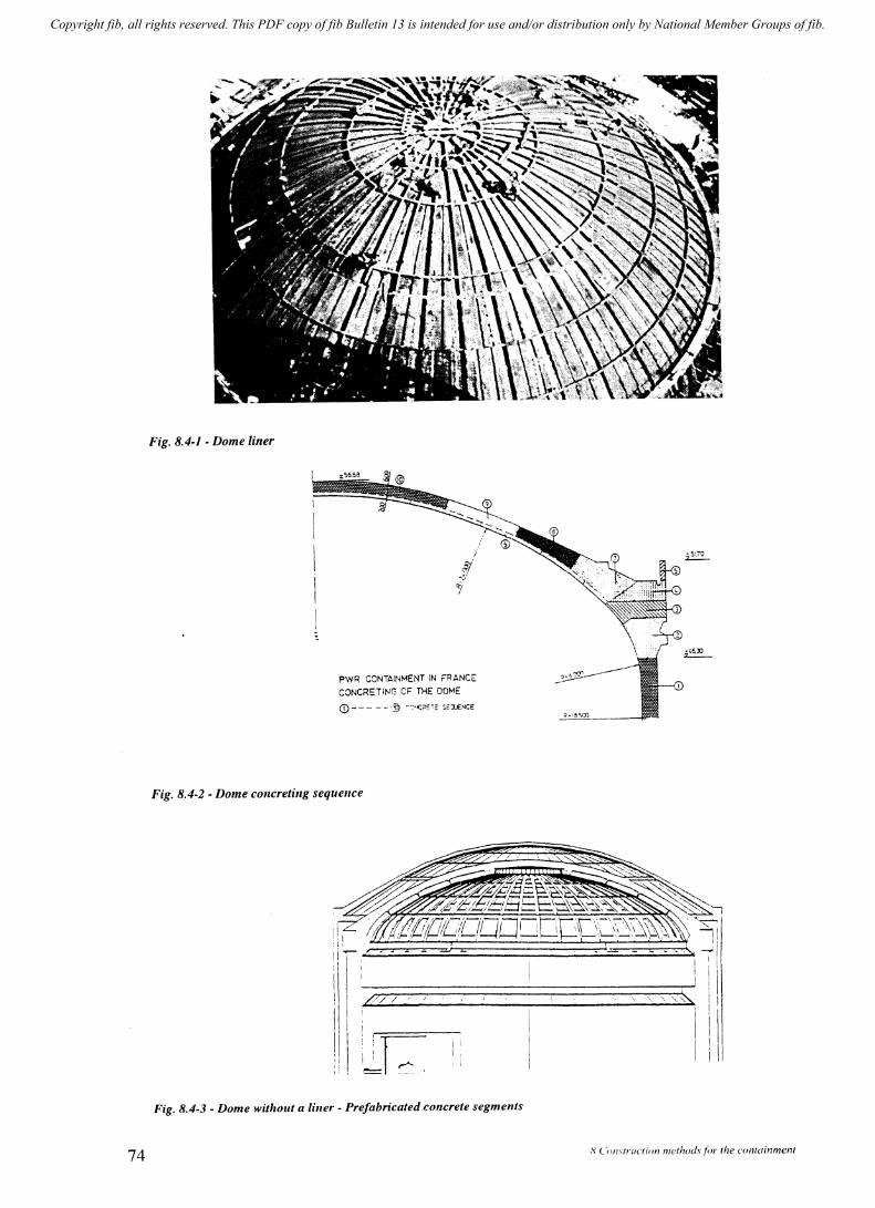
Copyright fib, all rights reserved. This PDF copy of fib Bulletin 13 is intended for use and/or distribution only by National Member Groups of fib.
74
Fig. 8.4-1 - Dome liner
PWR CONTAINMENT IN FRANCE
CONCRETiNG CF THE DOME
CD - _. - - -·9 CC·':>E'E S",-"NeE
Fig. 8.4-2 - Dome concreting sequence
/// /
i ;r ~. II
Fig. 8.4-3 - Dome without a liller - Prefabricated concrete segments
- - - .. ,'> .......
,'\ Construction ml!thod\'for the containment
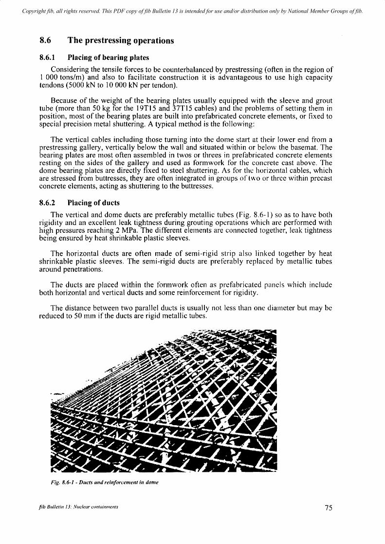
Copyright fib, all rights reserved. This PDF copy of fib Bulletin 13 is intended for use and/or distribution only by National Member Groups of fib.
8.6 The prestressing operations
8.6.1 Placing of bearing plates
Considering the tensile forces to be counterbalanced by prestressing (often in the region of 1 000 tons/m) and also to facilitate construction it is advantageous to use high capacity tendons (5000 kN to 10 000 kN per tendon).
Because of the weight of the bearing plates usual1y equipped with the sleeve and grout tube (more than 50 kg for the 19T15 and 37T15 cables) and the problems of setting them in position, most of the bearing plates are built into prefabricated concrete elements, or fixed to speciaJ precision metal shuttering. A typical method is the following:
The vertical cables including those turning into the dome start at their lower end from a prestressing gallery, vertically below the wall and situated within or belo\\-' the basemat. The bearing plates are most often assetnbled in twos or threes in prefabricated concrete elements resting on the sides of the gallery and used as formwork for the concrete cast above. The dOll1e bearing plates are directly fixed to steel shuttering. As for the horizontal cables, which are stressed from buttresses, they are often integrated in groups of two or three within precast concrete elements, acting as shuttering to the buttresses.
8.6.2 Placing of ducts
The vertical and dome ducts are preferably metallic tubes (Fig. 8.6-1) so as to have both rigidity and an excellent leak tightness during grouting operations which are performed with high pressures reaching 2 MPa. The different elements are connected together, leak tightness being ensured by heat shrinkable plastic sleeves.
The horizontal ducts are often made of semi-rigid strip also linked together by heat shrinkable plastic sleeves. The sen1i-rigid ducts are preferably replaced by metallic tubes around penetrations.
The ducts are placed within the formwork often as prefabricated panels which include both horizontal and vertical ducts and some reinforcement for rigidity.
The distance between two parallel dUdS is usually not less than one diameter but may be reduced to 50 mm if the ducts are rigid metallic tubes.
Fig. 8.6-/ - Ducts and reinforcement;11 ,lome
fib Bulletin 13: Nuclear containments 75
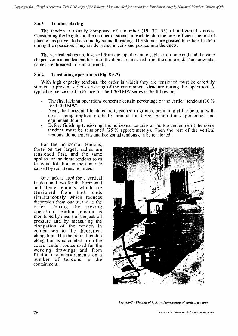
Copyright fib, all rights reserved. This PDF copy of fib Bulletin 13 is intended for use and/or distribution only by National Member Groups of fib.
8.6.3 Tendon placing
The tendon is usually composed of a number (19, 37, 55) of individual strands. Considering the length and the number of strands in each tendon the most efficient method of placing has proven to be strand by strand threading. The strands are greased to reduce friction during the operation. They are delivered in coils and pushed into the ducts.
The vertical cables are inserted from the top, the dome cables from one end and the cane shaped-vertical cables that turn into the dome are inserted from the dome end. The horizontal cables are threaded in from one end.
8.6.4 Tensioning Ol)erations (Fig. 8.6-2)
With high capacity tendons, the order in which they are tensioned must be carefully studied to prevent serious cracking of the contaimnent structure during this operation. A typical sequence used in France for the 1 300 MW series is the following:
The first jacking operations concern a cel1ain percentage of the vertical tendons (30 % for 1 300 MW). Next, the horizontal tendons are tensioned in groups, beginning at the bottom, with stress being applied gradually around the larger penetrations (personnel and equipment doors). Before finishing tensioning, the horizontal tendons at the top and some of the dome tendons must be tensioned (25 % approximately). Then the rest of the vertical tendons, dome tendons and horizontal tendons can be tensioned.
For the horizontal tendons, those on the largest radius are tensioned first, and the saIne applies for the dome tendons so as to avoid foliation in the concrete caused by radial tensi Ie forces.
One jack is used for a vertical tendon, and two for the horizontal and dome tendons which are tensioned from hoth ends sinllJltaneously which reduces dispersion from one strand to the other. During the jacking operation, tendon tension is l11onitored by means of the jack oil pressure and by nleasuring the elongation of the tendon in cOlnparison to the theoretical elongation. The theoretical tendon elongation is calculated from the coded tendon routes used for the working drawings and frol11 friction test measurelnents on a number of tendons In the containment.
76
Fig. 8.6-2 - Placillg of jack {lIId lemiollilllJ of verticallem/o",,,
8 (',)IIs(l'lI('/ioll IIIl"'lOdsfiJl' Ihe contail/ment
Copyright fib, all rights reserved. This PDF copy of fib Bulletin 13 is intended for use and/or distribution only by National Member Groups of fib.
8.6.5 Protection of prestressed tendons
> Bonded tendons
For bonded tendons grouting shall be carried out according to specifications with respect to the design and mixing of the grout and the execution of the work. Special attention should be paid to site control.
Grouting of long vertical tendons presents special problelns which have been noted equaI1y for tall structures such as television towers and concrete offshore platforms. Especially where strands are used bleeding has been observed in the topmost part of the cable. Nmnerous tests have been performed at full scale for purely vertical cables as well as for vertical cables turning into the donle.
The quality of the mix is essential with adequate retarded set grout and a thixotropic agent.
Furthermore particular nlethods are used such as installation of an extension pipe connected to the duct above the top anchor head of the vertical tendons, or grouting of ganlma shaped tendons performed in two successive stages.
The grouting of vertical tendons is performed froIn the lower anchorage at baselnat level at a grout pressure limited to 2.0 MPa.
Grouting pressure for horizontal tendons is perfonned at approxilnately 0.5 MPa.
Vents are provided at the top of horizontal cable ducts whenever they are displaced more than 1.20 m from the reference line, with drains at low points (which can also serve as grouting caps) where the difference in level is more than 1.20 m.
In order to avoid corrosion the delay behveen tensioning and grouting is strictly limited.
After the end of the grouting operations all cable anchor heads are sealed by concreting except vertical cables \vhich are otten protected with metal covers. Ho\vcver a limited number of cables are left ungrouted in order to fit them with monitoring dynamometers to check long term behaviour.
~ Unbonded tendons
For unbonded tendons corrosion protectioll is usually ensured hy injection into the ducts of a petrolatum-based cOlnpound consisting of a micro-crystalline wax with wetting agents, rust prevention additives and constituents formulated to be water displacing, self-healing and resistant to electrical conductivity. Sufticient viscosity at operating temperatures reduces the risk of outflow through loose joints behveen duct clements or through micro-cracks in the concrete.
The wax is a homogeneous compound thus avoiding the risk of separation between the different phases of the compound which could be a problem in the earlier greases in which alterations with time of the corrosion protection medium were possible due to losses of the oily (more volatile) component.
Whether the tendons are bonded or unbonded, particular care and protection or the tendons Inust be ensured by provision of protective agents during the storage stage bL:fore placing and tensioning.
fib Bulletin 13: Nue/eot' conl(lilllll(!II/.1' 77
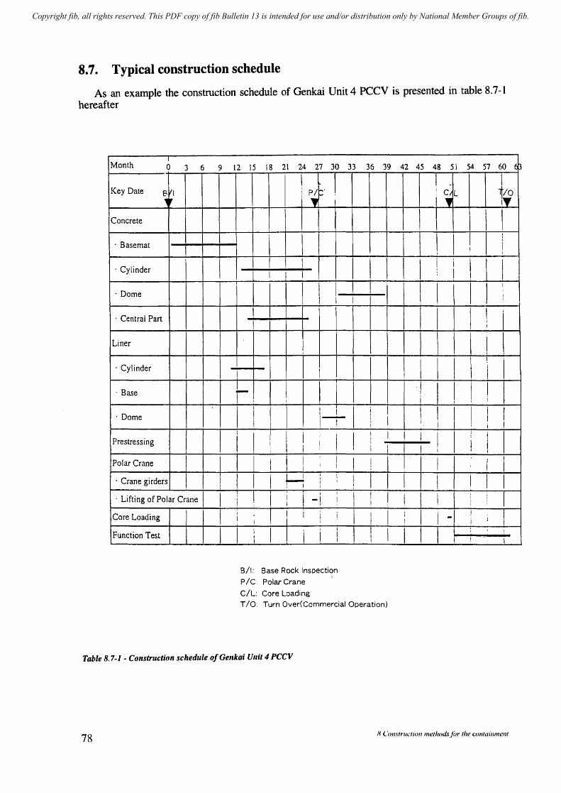
Copyright fib, all rights reserved. This PDF copy of fib Bulletin 13 is intended for use and/or distribution only by National Member Groups of fib.
8.7. Typical construction schedule
As an example the construction schedule of Genkai Unit 4 PCCV is presented in table 8.7-1 hereafter
I Month o 3 6
Key Date (3 ill
."
Concrete
· Basemat
· Cylinder I
· Dome
, Central Part
Liner
· Cylinder
, Base
· Dome
Prestressing
Polar Crane
· Crane girders I , Lifting of Polar Crane I
Core Loading
Function Test
9 12 15 18 21 24 27 30 33 36 39 42 45 48 51 54 57 60 $
I I
I , PIt:' . :, I
~/O I"
I I I I I I
I I I I I I i t I
I~I-+-I 1 I I I I
r. i t I l-r
I i I !
LJ : I
! I -i I
!
B/I: Base Rock Inspection
pic: Polar Crane
C/l: Core loading
I I I! I I \ !
I I I I I I! I ! I
I I I I I
-: ..... !---: I I I
I I
I -! I I
T 10: Turn Over(Commercial Operation)
I
I
T
Table 8.7-1 • Comtruction schedule of Genkai Unit 4 PCCV
78 R Construction methods/or the containment
Copyright fib, all rights reserved. This PDF copy of fib Bulletin 13 is intended for use and/or distribution only by National Member Groups of fib.
9 Some considerations on recent developments
9.1 Conceptual aspects
The safety approach to the next generations of NPP evaluated by IAEA includes different conceptual aspects or improvements which tnay influence the containtnent design:
in depth defence (independence of lines of defence),
active or passive systems requiring (or not) external action for overpressure protection, safety injection, emergency feed water, residual heat removal systems in the containment water storage tank, etc.
evolutionary approach (experience frolll previous plants),
I and C (information and control systems, tnan/machine interface), in view of presenting clear and appropriate information minimizing the possibilities for operator errors,
ilnprovement of plant behaviour during transients (thermal inertia and intervention delay),
severe accidents and improvetnents in containment design.
Concerning the containment:
it is in itself an in-depth defence passive systeln,
the independence and redundancy of systems and lines (active systems), influence the dimensions, geolnetry and loads on the containment for exanlple: four separate independent trains for safety systems and support functions linked to containment,
tlooding systems in accidental situations can be active or passive. The choice, which depends on reliability and experience, influences the containment design (evolutionary approach).
the thermal inertia in relation to safe delays of intervention may influence the dimensions of the core and steam generators and therefore the dimensions of the containment,
avoiding direct paths towards the environment in case of an accidental situation suggests a preference to double wall concepts,
the severe accidents including hydrogen combustion and corium spread are major design situations for future plants.
A sound design of the plant and thus of the containment, taking carefully into account the present day safety requirements but anticipating their evolution, is necessary.
Considering the volume of work and experience necessary to design an NPP, the containment being cOtTIpletely integrated within the overall design and architecture of the plant, it is practically necessary to standardise projects so that they can be adapted without major Inodifications to different enviromnental conditions: soil and SeiStllic conditions, aircraft crash, etc.
fib Bulletin 13: Nlh'lear cOlllainments 79
Copyright fib, all rights reserved. This PDF copy of fib Bulletin 13 is intended for use and/or distribution only by National Member Groups of fib.
9.2 Some new concepts in design
New concepts in design must take into consideration the previous remarks on safety, but also cost considerations including maintenance and life duration of the plant. Some of the new design concepts presently at basic design stage or advanced conceptual stage are very briefly presented hereafter.
They are limited to light water reactors whether PWR or BWR, all of them attempting to integrate the latest safety measures in an overall innovative balanced concept.
Part of the information and drawings of chapter 9.2 are from the proceedings of the International Conference on the EPR Project as published by SFEN [SFEN (1995)]
9.2.1 PWR European Pressurized Reactor (EPR)
See Fig. 9.2-1.
The European Pressurized Reactor (EPR) designed since 1992 by Framatome (France) and Siemens (Germany) takes into account:
the technological and operating experience of the two countries (evolutionary concept)~ In this aspect the safety of EPR is mainly based on active proven and redundant systems than on passive systems,
the common involvement and agreement on safety rules by the French and German Authorities,
the flexibility allowing for an easy adaptation to a range of soil conditions and internal events,
the possibility of severe accidents: hydrogen management, corium cooling,
a high availability and low maintenance cost,
a lengthened life duration of the plant (60 years).
The design of the containment resulting from the previous considerations and particularly the effect of severe accidents includes:
80
a double wall containment with no direct path for leakage. The inner containment is prestressed concrete (a synthetic liner is not excluded), the external containment is of reinforced concrete,
an increased internal volume (80000 m3) for avoiding a hydrogen concentration above 10 % in case of core melt,
a design pressure of 0.65 MPa (absolute) for the case of hydrogen combustion, higher than LOCA design pressure (0.55 MPa absolute) and as a consequence an increased prestressing force,
a thick basemat and a corium spreading room with several layers of thermal resistant materials, and a water storage facility at the bottom of containment (IRWST).
The basic design was completed in 1998.
9 Some considerations on recent developments
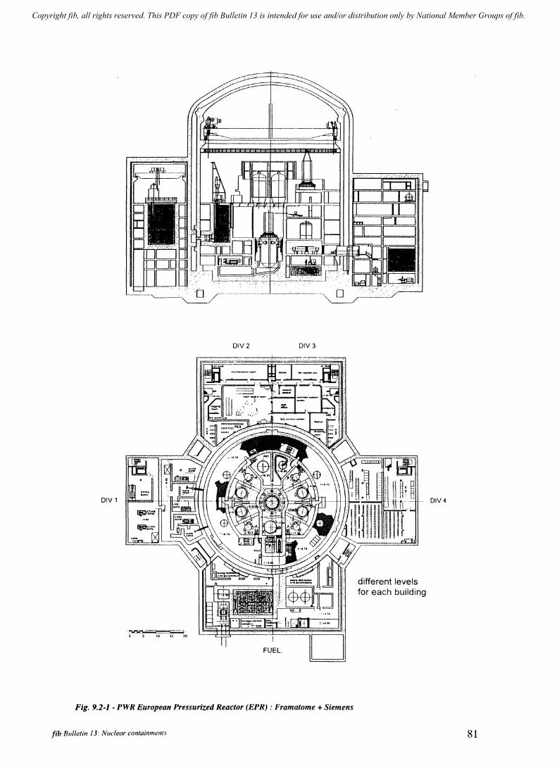
Copyright fib, all rights reserved. This PDF copy of fib Bulletin 13 is intended for use and/or distribution only by National Member Groups of fib.
DIV1
.~.--~.
o S 10 1~ 10
DIV2 DIV3
FUEl.
Fig. 9.2-1 - PWR European Pressurized Reactor (EPR) : Framatome + Siemens
fib Bulletin 13: Nuclear containments
different levels for each building
DIV4
81

Copyright fib, all rights reserved. This PDF copy of fib Bulletin 13 is intended for use and/or distribution only by National Member Groups of fib.
9.2.2 PWR system 80 (see Fig. 9.2-2)
Developed in the US by ABB combustion Engineering Nuclear Power, PWR System 80, is a 1300 MW advanced light water reactor. It has attained the final design approved stage.
The structure, a dual containment with an inner spherical steel primary containment almost 100 000 m3 in volulne and a cylindrical and dome shaped concrete shield, is similar to the containments of the Convoy PWRs designed by Siemens IKWU.
The large volume dampens the transient pressure build-up in the case of a severe accident and limits the hydrogen concentration.
System 80 + Integrated Nuclear Island Structure
Ground level - .::----1 ~ .... It' Pipe Chase -1 ! elf ~-.
Source: ABB·CE EFW Pump Compartment Safeguard Systems Reactor IRWST Access Aisle
Compartment Cavity mv· Emergency Feedwaler; IRWST 'In-Conlainmenl Refueling Waler Siorage Tank; HVAC· Healing, Venlilalion, and Air Condilioning
Fig. 9.2-2 - A.dvanced Pressure H1ater Reactors
82 9 Sume considerations on recent developments
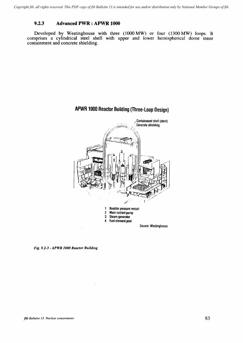
Copyright fib, all rights reserved. This PDF copy of fib Bulletin 13 is intended for use and/or distribution only by National Member Groups of fib.
9.2.3 Advanced PWR: APWR 1000
Developed by Westinghouse with three (1000 MW) or four (1300 MW) loops. It comprises a cylindrical steel shell with upper and lower hemispherical dome inner containment and concrete shielding.
APWR 1000 Reactor Building (Three-loop Design)
Fig. 9.2-3 - APWR 1000 Reactor Buildillg
fib Bulletin 13: Nuclear containments
I Containment shell (steel) " Concrete shielding
/' I'
1 Reactor pressure vessel 2 Main coolanl pump 3 Steam generalor 4 Fuel elemenl pool
Source: Westinghouse
83
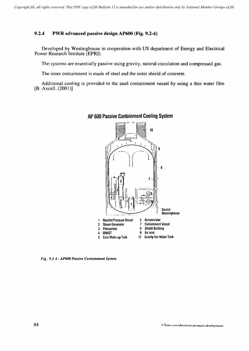
Copyright fib, all rights reserved. This PDF copy of fib Bulletin 13 is intended for use and/or distribution only by National Member Groups of fib.
9.2.4 PWR advanced passive design AP600 (Fig. 9.2-4)
Developed by Westinghouse in cooperation with US department of Energy and Electrical Power Research Institute (EPRI).
The systems are essentially passive using gravity, natural circulation and compressed gas.
The inner containment is made of steel and the outer shield of concrete.
Additional coohng is provided to the steel containment vessel by using a thin water film [B. Axcell, (2001)]
AP 600 Passive Containment Cooling System
~'-~-.•
~ ~-
"':: .. ~ .. 10 'c .. ' '~
/~ I I· ! I '~::-.... / I !
-9
If - 8
.- ~~----_.-----.
1 Reactor Pressure Vessel 6 Accumulator 2 Steam Generator 7 Containment Vessel 3 Pressurizer B Shield Building 4 IRWST 9 Air Inlet 5 Core Make-up Tank 10 Gravity-led Water Tank
Fig. 9.2-4 - AP600 Passive Colltainme,1t System
84 9 Some (.'O/l.\-;deratiolls on recent developments
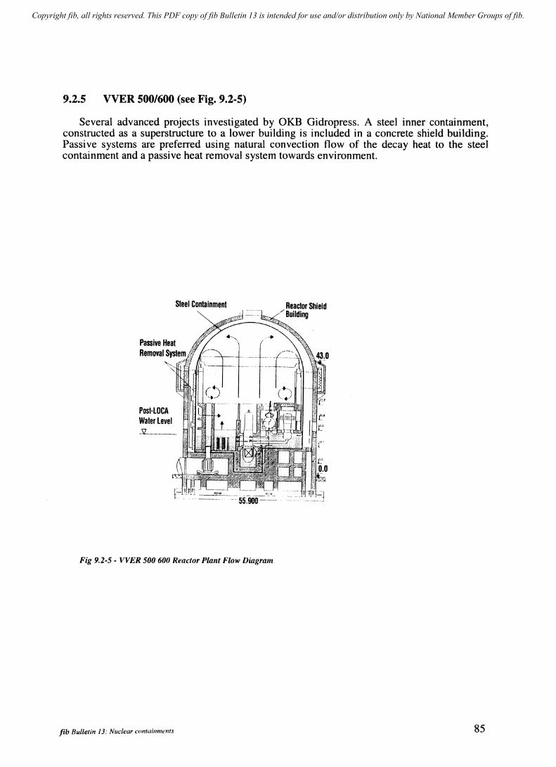
Copyright fib, all rights reserved. This PDF copy of fib Bulletin 13 is intended for use and/or distribution only by National Member Groups of fib.
9.2.5 VVER 500/600 (see Fig. 9.2-5)
Several advanced projects investigated by OKB Gidropress. A steel inner containment, constructed as a superstructure to a lower building is included in a concrete shield building. Passive systems are preferred using natural convection flow of the decay heat to the steel containment and a passive heat removal system towards environment.
PosHOCA Water level
Steel Containment
_'11-_""" "_"" __ _
Fig 9.2-5 - VVER 500 600 Reactor Plallt Flow Diagram
fib Bulletin 13: Nuclear containments
Reactor Shield Building
85
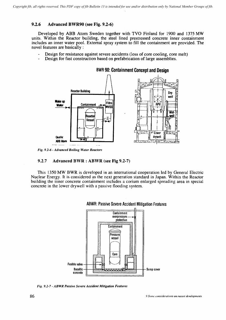
Copyright fib, all rights reserved. This PDF copy of fib Bulletin 13 is intended for use and/or distribution only by National Member Groups of fib.
9.2.6 Advanced BWR90 (see Fig. 9.2-6)
Developed by ABB Atom Sweden together with Tva Finland for 1900 and 1375 MW units. Within the Reactor building, the steel lined prestressed concrete inner containment includes an inner water pool. External spray system to fill the containment are provided. The novel features are basicall y :
Design for resistance against severe accidents (loss of core cooling, core melt) Design for fast construction based on prefabrication of large assemblies.
Makeup Wiler
QueUe: ABBAIom
BWR 90: Containment Concept and Design
Reactor Building
Containment
Fig. 9.2-6 - Advanced Boiling Water Reactors
9.2.7 Advanced BWR : ABWR (see Fig 9.2-7)
This 1350 MW BWR is developed in an international cooperation led by General Electric Nuclear Energy. It is considered as the next generation standard in Japan. Within the Reactor building the inner concrete containment includes a corium enlarged spreading area in special concrete in the lower drywell with a passive flooding system.
86
A8WR: Passive Severe Accident Mitigation Features
Fusible valve Basaltic
concrete
~.
Containment ~
overpressure _ protection
/I:~/////.. '////. ///. '/
;~ Containment ~ ~
~ I:
/ Pressure vessel
/
~
[;; -v; Core %
~-/, - 7~ ~ ~
r-
.A. I: ~ I: ,....
I:W Y/////////////-,/,:: ~
Fig. 9.2-7 - ABWR Passive Severe Accident Mitigation Features
Sump cover
9 Some considerations on recent developments
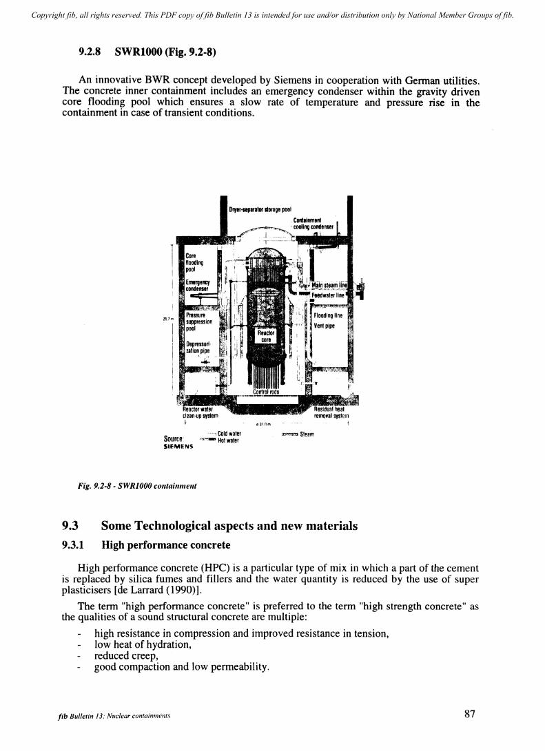
Copyright fib, all rights reserved. This PDF copy of fib Bulletin 13 is intended for use and/or distribution only by National Member Groups of fib.
9.2.8 SWRI000 (Fig. 9.2-8)
An innovative BWR concept developed by Siemens in cooperation with German utilities. The concrete inner containment includes an emergency condenser within the gravity driven core flooding pool which ensures a slow rate of temperature and pressure rise in the containment in case of transient conditions.
Dryer·nparator lIoraoe pool
PUm
Core flooding pool
Source' S'FMFN~
.• 1 Cold water ",...".,., Hot water
Fig. 9.2-8 - SWRIOOO colltaillmellt
a310m
..,..".,..", Steam
9.3 Some Technological aspects and new materials
9.3.1 High performance concrete
High performance concrete (HPC) is a particular type of mix in which a part of the cement is replaced by silica fumes and fillers and the water quantity is reduced by the use of super plasticisers [de Larrard (1990)].
The term "high performance concrete" is preferred to the term "high strength concrete" as the qualities of a sound structural concrete are multiple:
high resistance in compression and improved resistance in tension, low heat of hydration, reduced creep, good compaction and low permeability.
fib Bulletin 13: Nuclear containments 87
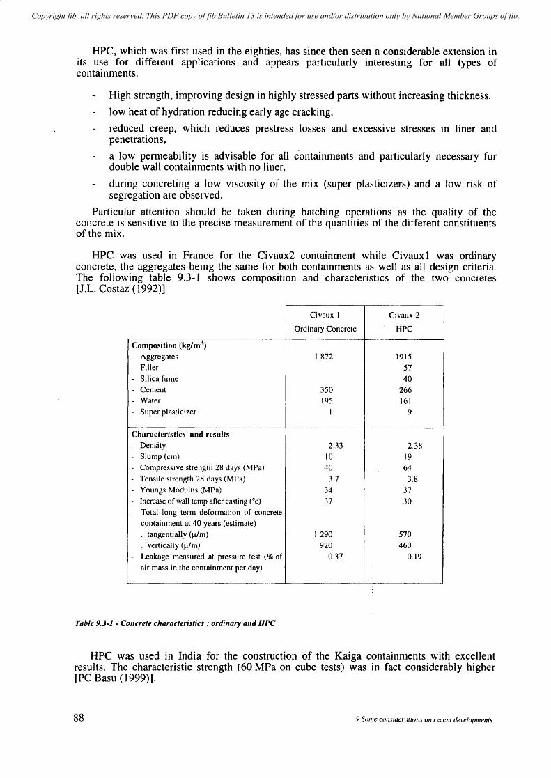
Copyright fib, all rights reserved. This PDF copy of fib Bulletin 13 is intended for use and/or distribution only by National Member Groups of fib.
HPC, which was first used in the eighties, has since then seen a considerable extension in its use for different applications and appears particularly interesting for all types of containments.
High strength, improving design in highly stressed parts without increasing thickness,
low heat of hydration reducing early age cracking,
reduced creep, which reduces prestress losses and excessive stresses in liner and penetrations,
a low permeability is advisable for all containments and particularly necessary for double wa) I containments with no liner,
during concreting a low viscosity of the mix (super plasticizers) and a low risk of segregation are observed.
Particular attention should be taken during batching operations as the quality of the concrete is sensitive to the precise measurement of the quantities of the different constituents of the mix.
HPC was used in France for the Civaux2 containment while Civaux 1 was ordinary concrete, the aggregates being the same for both containments as well as all design criteria. The following table 9.3-1 shows composition and characteristics of the two concretes [J.L. Costaz (1992)]
Civaux I Civaux 2
Ordinary Concrete HPC
Composition (kglm3)
- Aggregates t 872 1915 - Filler 57
- Silica fume 40 - Cement 350 266 - Water 195 161 - Super plasticizer I 9
Characteristics and results - Density 2.33 2.38 - Slump (em) 10 19
- Compressive strength 28 days (MPa) 40 64 - Tensile strength 28 days (MPa) 3.7 3.8
- Youngs Modulus (MPa) 34 37 - Increase of wall temp after casting (Oc) 37 30 - Total long term deformation of concrete
containment at 40 years (estimate)
. tangentially (1J/m) 1290 570
. vertically (1J/m) 920 460
- Leakage measured at pressure test (% of 0.37 0.19
air mass in the containment per day)
Table 9.3-1 - Concrete characteristics: ordinary and HPC
HPC was used in India for the construction of the Kaiga containments with excellent results. The characteristic strength (60 MPa on cube tests) was in fact considerably higher [PC Basu (1999)].
88 9 Some consideratiol/S on recent developments
Copyright fib, all rights reserved. This PDF copy of fib Bulletin 13 is intended for use and/or distribution only by National Member Groups of fib.
9.3.2 High capacity prestressing units
High capacity prestressing tendons have existed for many years. As early as 1939 prestressing tendons of 1000 tons effective force were placed to reinforce and pin-down to the foundation the gravity dam of Cheurfas in Algeria. In the late fifties the concrete pressure vessels of Marcoule in France were prestressed with tendons also of 1000 tons effective force, each tendon being made of a number of parallel wires 5 mm in diameter and protected by a bituminous coating. The anchorage heads of large dimensions were lifted using several jacks and transferred on to large resting blocks. Both examples were successful but reflect clever craftmanship well-adapted to some specific projects rather than advanced technology.
The tendency developed over the last few decades by the specialized process companies is to propose a complete set of products including all suitable equipment for the prestressing process: anchorage components, ducts, tensioning equipment, injection (cement grout or wax) and sealing off. The different companies have globally converged towards the use of strands (usually 15 to 16 mm in diameter) rather than paralJel wires and towards the individual anchoring of strands by a wedge system.
The experience gained by the extensive use of such tendons for many types of structures (bridges, containments, buildings, etc.) and the strict requirements which the complete process must meet in order to be commercialized is undoubtedly a factor of safety.
For many structures a limited tendon strength is sufficient, but for containments where high levels of bi-axial prestressing forces are required and space for the ducts in the concrete is limited due to the density of reinforcement and number of discontinuities, the optimum unit tendon strength should be high.
In the seventies, the ultimate load of the tendons did not exceed 3000 kN whereas in the nineties. a typical tendon for containments has a capacity of 10 000 kN and even 15 000 kN is possible. Such tendons and all corresponding equipnlent seem, as far as load capacity is concerned, best adapted to containments particularly of the PWR series where prestressing forces are high.
Typical of such tendons is the 55 strand unit with an ultimate load of 14 300 kN with standard strands and 15 345 kN with super strands, while the UTS in both cases remains 1860 MPa.
Such tendons have been used experimentally in the Civaux2 containment.
9.3.3 Composite liner
The use of a composite liner has also been investigated. It is a coating system of fibregla~s which can improve the function of leaktight barrier if no steel liner is provided [R. Danisch (1999)].
Resin based on vinyl-ester or epoxy resin are most suitable for use as a coating system. The typical layer build-up of a coating system consists of the primer coat, a filler layer, one or more laminates and a sealant. The layer thickness totals about 3 to 8 mm depending on the design.
The coating system must be capable of safely guaranteeing a leaktight function over the entire service life of a power plant under normal operating conditions as well as during and subsequent to accidents. On the basis of laboratory tests, it is considered that this requirement can be met even at high temperature (I50°C).
fib Bulletin 13: Nuclear contail/lITcnt.l· 89
Copyright fib, all rights reserved. This PDF copy of fib Bulletin 13 is intended for use and/or distribution only by National Member Groups of fib.
9.4 Large scale models
9.4.1 General
One may distinguish different types of models, the aim of which are different.
Fundamental models which test the behaviour of a structure or material, for instance behaviour of shear walls submitted to seismic conditions.
Their scope, however useful for containment design, can be extended to any type of structure, and their results integrated within general regulations. The results of such models are often compared to those obtained from analytical models.
Specific models such as shear and pull out capacity of liner studs embedded in concrete.
The results in terms of structural deformations and leakage performed during the Structural Integrity Tests (SIT), and the observations and measure,ments performed during the entire life of each containment can be considered as the testing of full scale models. The performance of such tests are developed in chapter 10.
Large scale models which aim at representing the behaviour of a containment under different types of loads and in particular beyond design loads and rupture conditions.
Examples of such large scale models are presented hereafter.
9.4.2 Large scale EDF (France) test at Civaux (MAEVA mock-up) (Fig. 9.4-1)
90
The aim of the MAEV A mock-up constructed by Freyssinet is to study the mechanical and leak-tightness behaviour of a prestressed double wall containment without liner for loads corresponding to design conditions and extending to beyond design conditions and up to rupture [L. Granger (1997)], [Po Guinet (1997)].
A series of tests are performed successively with air and with steam for varying pressure and temperature so as to take into account the thermal effects and the propagation of the steam through the concrete as such conditions are not represented during SIT.
The mock-up consists in a 5 m high prestressed high performance concrete cylinder with an internal radius of 8 m (scale 1/3 for mechanical behaviour) and 1.2 m thickness (full scale for leak-tightness behaviour).
The cylinder is closed by two leak-tight slabs linked together by the vertical prestressing. Half of the internal surface of the cylinder is covered with a composite liner to study its behaviour under pressure and steam conditions.
The tests have and will be performed during years 1999 and 2001. The large amount of collected data including the thermal propagation through the concrete, the steam and water migration through the concrete, and the mechanical behaviour in relation to pressure and temperature will be compared with the values resulting from predictive computations, analyzed and be useful for future projects.
9 Some considerations on recent developments
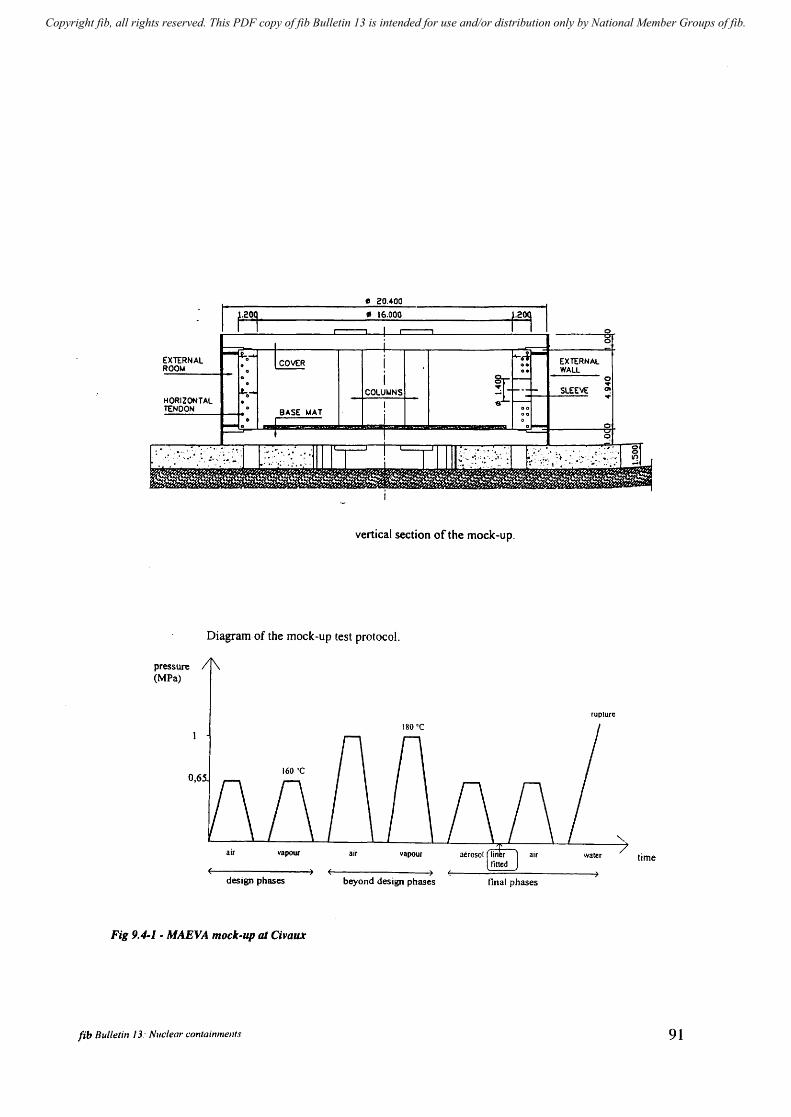
Copyright fib, all rights reserved. This PDF copy of fib Bulletin 13 is intended for use and/or distribution only by National Member Groups of fib.
EXTERNAL ROOI.A
.~." .
vertical section of the mock-up.
Diagram of the mock-up test protocol.
pressure (MPa)
0,6
design phases
Fig 9.4-1 - MAEVA mock-up at Civaur
fib Bulletin 13: Nuclear containments
beyond design phases final phases
rupture
time
91
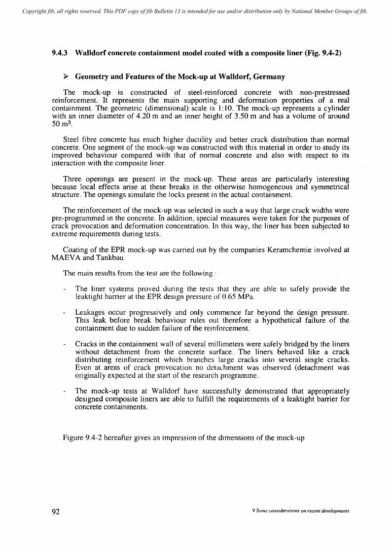
Copyright fib, all rights reserved. This PDF copy of fib Bulletin 13 is intended for use and/or distribution only by National Member Groups of fib.
9.4.3 Walldorf concrete containment model coated with a composite liner (Fig. 9.4-2)
~ Geometry and Features of the Mock-up at Walldorf, Germany
The mock-up is constructed of steel-reinforced concrete with non-prestressed reinforcement. It represents the main supporting and deformation properties of a real containment. The geometric (dimensional) scale is 1: 10. The mock-up represents a cylinder with an inner diameter of 4.20 m and an inner height of 3.50 m and has a volume of around 50m3 .
Steel fibre concrete has much higher ductility and better crack distribution than normal concrete. One segment of the mock-up was constructed with this material in order to study its improved behaviour compared with that of normal concrete and also with respect to its interaction with the composite liner.
Three openings are present in the mock-up. These areas are particularly interesting because local effects arise at these breaks in the otherwise homogeneous and symmetrical structure. The openings simulate the locks present in the actual containment.
The reinforcement of the mock-up was selected in such a way that large crack widths were pre-programmed in the concrete. In addition, special measures were taken for the purposes of crack provocation and deformation concentration. In this way, the liner has been subjected to extreme requirements during tests.
Coating of the EPR mock-up was carried out by the companies Keramchemie involved at MAEV A and Tankbau.
92
The main results from the test are the following:
The liner systems proved during the tests that they are able to safely provide the leaktight barrier at the EPR design pressure of 0.65 MPa.
Leakages occur progressively and only commence far beyond the design pressure. This leak before break behaviour rules out therefore a hypothetical failure of the containment due to sudden failure of the reinforcement.
Cracks in the containment wall of several mi lIimeters were safely bridged by the liners without detachment from the concrete surface. The liners behaved like a crack distributing reinforcement which branches large cracks into several single cracks. Even at areas of crack provocation no detachment was observed (detachment was originally expected at the start of the research programme.
The mock-up tests at Walldorf have successfully demonstrated that appropriately designed composite liners are able to fulfill the requirements of a leaktight barrier for concrete containments.
Figure 9.4-2 hereafter gives an impression of the dimensions of the mock-up
9 Some cOl1side,.af ions on recent developments
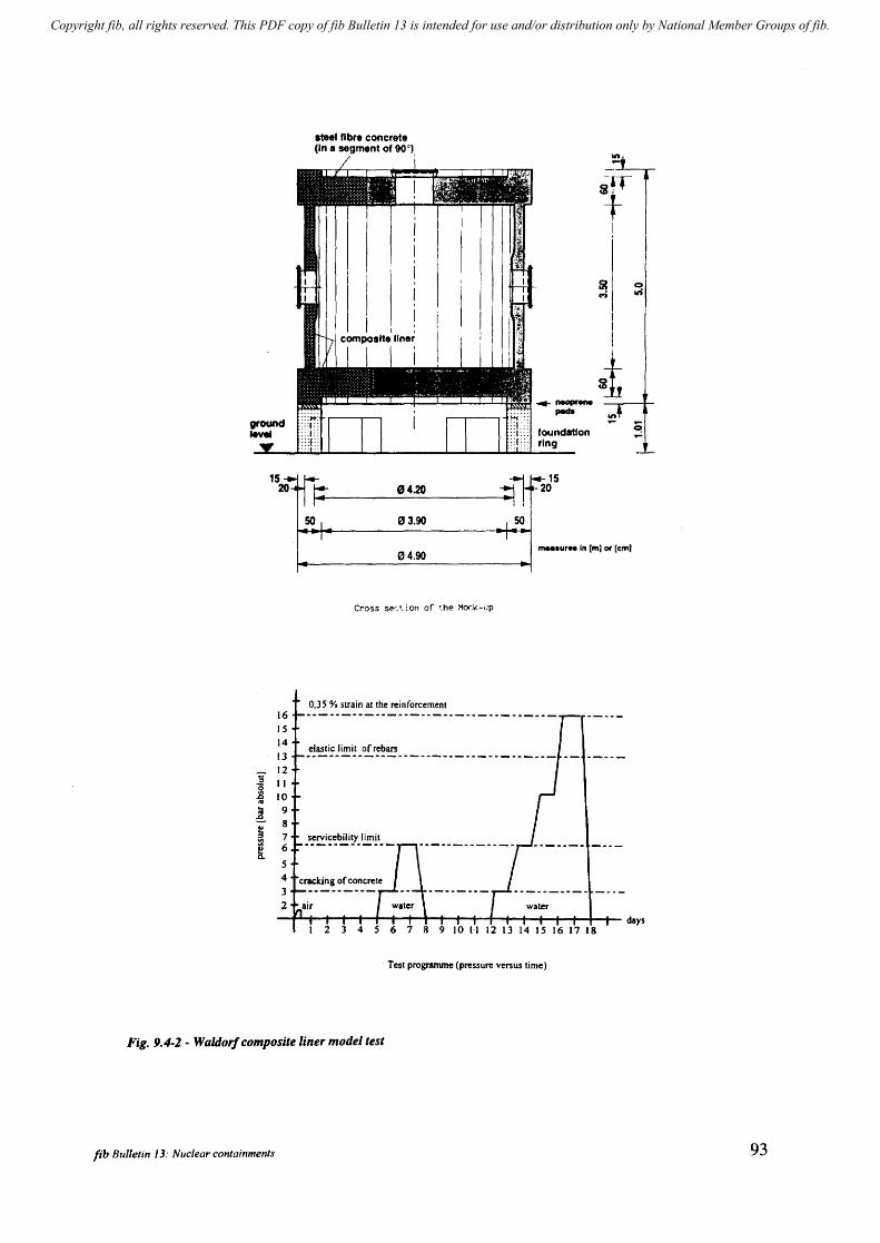
Copyright fib, all rights reserved. This PDF copy of fib Bulletin 13 is intended for use and/or distribution only by National Member Groups of fib.
'3 "0 ~ ftI
! ~ [
15 20
16 15 14
13
12 II 10 9 8 7 6
5 4
3 2
11'" fibre concrete (In a segment of 90°),
" 4.20
SO " 3.90
" 4.90
Cross SE'r.t. ion or ".he Mor.k-.:p
0,35 % strain at the reinforcement
eiastic limit ofrebars
~ c-;
I I
I
~ ~ neopreM
peda ~
foundatlon ring
15
-=1, 20
SO
"...ur .. In [m) Of [em'
14 15 16 17 18
Test prognunme (pressure versus time)
Fig. 9.4-2 - Waldorf composite liner model test
fib BlIlIetin J 3: Nuclear containments
~ 1ft
~
93

Copyright fib, all rights reserved. This PDF copy of fib Bulletin 13 is intended for use and/or distribution only by National Member Groups of fib.
9.4.4 NUPEC and NRC model of a PCCV at Sandia National Laboratories (Fig. 9.4-3)
94
Sandia National Laboratories is constructing a 1:4 scale prestressed concrete containment vessel as part of a containment research program co-sponsored by the Nuclear Power Engineering Corporation (NUPEC) of Japan and the US Nuclear Regulatory Commission (NRC) [Hessheimer (1997)].
The model represents the containment of a PWR with a steel liner constructed in Japan (Ohi PWR) and represents both prestressing and reinforcement. The testing program incl udes several pressure tests at design pressure and one test to rupture. The temperature effects are not represented.
The objectives of the test are to provide information on the failure modes such as : free-field liner tearing, tearing at a discontinuity, shear failure in junction zones, leakages, tendon failures.
The extensive monitoring system will enable comparison with the effective SIT performed in 1992 on the constructed containment in Japan, and also serve as a validation to the numerical predictive computations which were performed.
The dimensions of the model (16.4 m high from base liner, 10.75 m diameter and several hatches and penetrations represented) are shown on the following figure.
The Structural Integrity Test (SIT) and Limit State Test (LST) were completed in late 2000 and publication of the results is expected during 2001.
9 Some considerations on recent developments
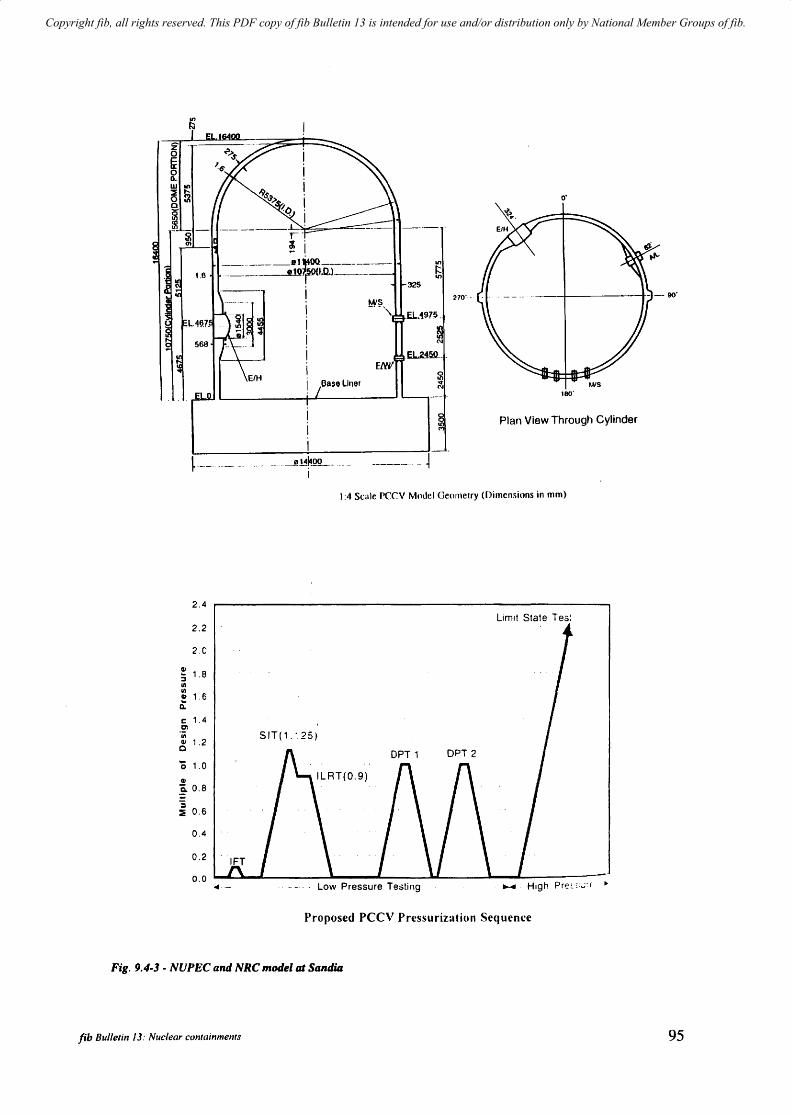
Copyright fib, all rights reserved. This PDF copy of fib Bulletin 13 is intended for use and/or distribution only by National Member Groups of fib.
i i i i i
. __ ._. ____ ..L:~ . ...::::::---== r~ . ... I
==~-,~~~)-==~-1.6 325
~--.- ----
i i i i i I i Bas, Lin"
EfH
.... _ .. _"l~~_Q~L .. __ ._i
---- - ~
o·
270' -
180'
Plan View Through Cylinder
1:4 Scale PCCV Model Gcornclry (Dimen.<;ions in mm)
2.4
limit State Tes! 2.2
2.C
G> 1.B :;
III III
1.6 G> Q:
c 1.4 Ol u; SIT('.~25) ell 1.2
Q
'0 1.0
G>
~ 0.8
:i :ii 0.6
0.4
0.2
0.0 ... - Low Pressure Testing .... High Pre~ c";: t ~
Proposed pee" Pressurization Sequence
Fig. 9.4-3 - NUPEC and NRC model at Sandia
fib Bulletin 13: Nllelear containments 95
Copyright fib, all rights reserved. This PDF copy of fib Bulletin 13 is intended for use and/or distribution only by National Member Groups of fib.
9.4.5 Hualien mock-up
The mock-up built in Taiwan at Hualien by the end of 1992 is a cylindrical concrete containment scaled 1/4 aimed to obtain earthquake induced soil-structure interaction (SSI), data for a stiff soil site having similar prototypical NPP soil conditions and aimed at evaluating methodologies and computer codes used in SSI analysis of NPP structures.
9.4.6 Experimental studies on RCCV for ABWR in Japan (see Fig. 9.4-4)
Adoption of a reinforced concrete containment vessel (RCCV) is one of the unique features of ABWR, because RCCV is the first structure of its kind in the sense that it is structurally combined with the reactor building.
Therefore a series of experimental studies were undertaken as shown in Fig. 9.4-4 which consists of basic study aiming at accumulating design data, verification studies by partial structural element models and an entire scaled model intended to verify the structural characteristics and integrity of RCCV.
A large-scale test was conducted by a l/6th scale entire model simulated to RCCV which is combined with reactor building through building slabs, pool girders and so on.
As a result of testing by internal pressure, temperature and seismic loadings to determine the structural behaviour of RCCV, it was found that under design loading conditions no excessive cracks were observed in concrete, deformations indicated that the vessel behaved in an elastic manner, and strains observed in rebars were within the allowable elastic limits.
In addition it was confirmed that an FEM elastic analysis method is capable of determining the structural behaviour of concrete vessels. A final test by horizontal loading up to failure proved that the model possesses the ultimate strength equivalent to 3.6 times the design loading.
96 9 Some considerations on recent developments
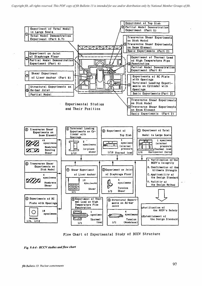
Copyright fib, all rights reserved. This PDF copy of fib Bulletin 13 is intended for use and/or distribution only by National Member Groups of fib.
Experiment of Top Slab ICD Partial Nodel Demonstration Experiment of Total Nodel
/ Experl"ent (Part 5) kD In lJrge Scale
Total Model Demonstration Transverse Shear Experiments Experiment (Part 6.7) on 01 sk Mode I ~ ~ Transverse Shear Experiments
:'~/f~.J,ll"t,l"I/"'I7"J.;"": on Beam'Element
I / Basic Experiments ~Pnrt 2) Experiment on Joint
~ or Diaphragm Floor , t-"i..;---------f-l--~, Experiment of Thermal load ~ Partial Nodel Demonstrallo~~ ~l.l/lGl 1 01 HI&h Te"peratpre Pipe Experiment (Part 4) I - - kB: Penetration
I N : ........ IIT~'" ~ Partial Model Demonstration
Shear Experiment ~ 0: ~ ~ ./'" I Experiment (Part 8)
~ ~ : ~; r-'l' Experiments of RC Plate of liner Anchor (Part 8) I ~;' . .wlth Open I ngs
~ LLlL r-- ~F- UiE 11/7'1 Torsionel londing Experi-~: ~ TIl! ments on Cylinder with Structural Experiments on : 1--: 1 I@ Re-bar Joint .:b. ... :.:.:.:.:.:.:.:;;.;:.;: .. "::' ./ Open I ngs \.. t----~;~~~........... -- Basic Experiments (Part 3) Parti a I Mode 1
~ Transverse Shear Experiments Experimental Studies on Disk Model
~ Transverse Shear Experlme~ts and Their Position on Beam Element Basic Experiments <Part 2)
® Transverse Shear <!> Tors I ona I Load I n& CD Experiment of " CD Experiment of Total Experllllenls on Experiments on Cy-
Bealll Element llnder vllh Top Slab Model In Lar,e Scale Openln,s
4S ~ m 1 . ~. I specl.en
~ specimens 2
~ specimen Inlernal specimens Internal pressure Membrane
In-plane pressure I Thermal load tZJ CZJ Bendin& shear 1/10
- 1/6 Horizontal force Shear 1/12 Thermal load
+ J A. Verification of the
® Transverse Shear t t RCCY's lnte,rlty Experiments on
@Experllllent B,. Can fl rma tl on 0 f the
Disk Model (i) Shear Experiment on Joint UlllDate Stren&lh
.. ~ of Liner Anchor of Dlaphra,m Floor C.Appllcabllltyof specimens the Desl,n Standard
~ 10
~ .. n. valid ~ lr of IoIelibrane SpE:(;ilnt;ns sp£:\:!lIIens
Shear ~4.{i$ the Desl~n Method
Tension Shear Shear U 1/1 113
~ Experllllents of RC (IDExperllllen t 0 f Ther- ® Struc tural .Experl-Plate with Openln,s .at Load on Hl,h ments on Re-bar
Temperature Pipe Joint pYerlflcatlon of
@] r+ Pene ira t 1 on 18 .. the RCCV's Safely
~I specllllcns . specilllen -r: i~ spcclaens
pEstabllshlllent of a:::::JC ... ..,. ~
Tension the Desl,n Standard ... -...... Theraal 1/6. 1112
1/1 load III (MeSllbrane)
Flow Chart of Experimental study of RCCV structure
Fig. 9.4-4 - RCCV studies and flow chart
fib Bulletin J 3: Nuclear COl1tainments 97
Copyright fib, all rights reserved. This PDF copy of fib Bulletin 13 is intended for use and/or distribution only by National Member Groups of fib.
9.4-7 SIZEWELL B 1/10TH SCALE MODEL PCCV TEST IN THE UK (SEE FIG. 9.4-5)
~ Introduction
Sizewell B is the first, and at present the only, commercial PWR station to be built in the UK and is owned and operated by British Energy. In order to broaden the understanding of the structural behaviour of the Sizewell B primary containment building and to fulfil a commitment to HM Nuclear Installations Inspectorate (NIl), the former Centra] Electricity Generating Board commissioned the design, construction and testing to failure of a representative prestressed concrete III oth scale model.
~ Aims of the Model Test
The aims of the Model Test were to provide:
Additional validation of the load analysis methods in the linear and non-linear structural response ranges, including local behaviour of major penetrations.
Assessment of the ultimate structural capability of the model and its relationship to the full scale containment.
Assessment of the likely failure mode of the full-scale containment.
Evidence of near elastic response in the model at ISIT pressure, which reaches approximately 0.5 MPa absolute at 1.15 DBA.
~ Model Characteristics
The model represented a scaled version of the full size structure. The main differences between the model and the full scale containment were as follows:
no steel liner
thickened base slab
hydraulic loading.
» Construction & Testing
The model was constructed under a strict quality control regime between May 1988 and June 1989 and was tested in July 1989. Over 400 built-in strain gauges and 220 externally fitted measuring devices and tendon anchorage load cells were provided. The model was subjected to three short cycles and one with a 24 h duration at ISIT pressure, to check the response and assess the creep characteristics of the model. The ultimate load test involved raising the pressure steadily until gross and inelastic deformation occurred.
Results and Analysis
~ Elastic Tests
The elastic behaviour of the wall and dome was assessed until 0.5 MPa absolute pressure (IS IT pressure).
98 9 Some considerations on recent developments
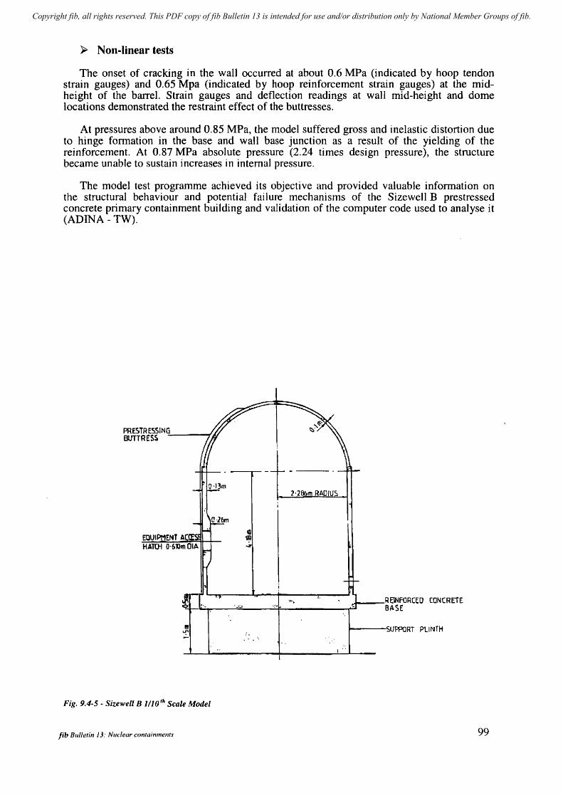
Copyright fib, all rights reserved. This PDF copy of fib Bulletin 13 is intended for use and/or distribution only by National Member Groups of fib.
~ Non-linear tests
The onset of cracking in the wall occurred at about 0.6 MPa (indicated by hoop tendon strain gauges) and 0.65 Mpa (indicated by hoop reinforcement strain gauges) at the midheight of the barrel. Strain gauges and deflection readings at wall mid-height and dome locations demonstrated the restraint effect of the buttresses.
At pressures above around 0.85 MPa, the model suffered gross and inelastic distortion due to hinge fonnation in the base and wall base junction as a result of the yielding of the reinforcement. At 0.87 MPa absolute pressure (2.24 times design pressure), the structure became unable to sustain increases in internal pressure.
The model test programme achieved its objective and provided valuable information on the structural behaviour and potential failure mechanisms of the Sizewell B prestressed concrete primary containment building and validation of the computer code used to analyse it (ADINA - TW).
PRESTREs:SING=--__ ~ BUTTRESS
2'2Bbm RADIUS
......... __ RElNfORCEO CONCREiE 9-.~------~-~---~~--------~~ BASE
.,..,
I----SUPPORT PLINTH
Fig. 9.4-5 - Sizewell B 11lO,h Scale Model
fib Bulletin J 3: Nuclear containments 99

Copyright fib, all rights reserved. This PDF copy of fib Bulletin 13 is intended for use and/or distribution only by National Member Groups of fib.
10 Monitoring and inspection program of containments
10.1 General (L.M. Smith, (2000) I
As a common practice, it is required that a containn1ent vessel shall be tested after construction and periodically during operation, in order to demonstrate that the intended performance of the vessel has been initially attained and further maintained.
An acceptance test denominated Initial Structural Integrity Test (lSIT) is performed to verify that the containment is able to withstand satisfactorily the specified design basis pressure Pa. A pre-operational pressure test is also specified which is performed after piping is in place to check the leak-tightness of the confinement. The plants may then start to operate.
The i tl-service surveillance (I S I) program veri lies at specii1ed intervals and during the entire life of the plant that the structure is sound and the design margins maintained. The lSI program includes pressure tests during which leakage ratc is controlled. The SIT protocol and lSI program will depend on the specincities of the containmcnt:
grouted or non grouted tendons, liner or no liner, prototype or reconduction of an existing plant.
The testing or the contail1lnent requires adequate instrumentation of the structure to check the strains and stresses in the structure and in the prestressing tendons, and to evaluate the deferred effects due to shrinkage, creep, and relaxation.
The test conditions and schedules, the measurements to he performed, and the acceptance criteria are defined in different codes and standards for different countries and practice.
10.2 Codes and standards
Comprehensive requirements on test procedures and on acceptance criteria have been issued in different countries, for the initial structural integrity test (ISIT) which is usually also the initial test for verification of leakage, as well as for the In Service Inspection (lSI).
The first codification \\'as American and was issued by the National Regulatory Commission and some other institutions in the USA. Those basic rules have been systematically applied in the USA and also in nU01erous other countries world wide and have been updated progressively. They cover all types of prestressed containments with a steel liner for unbonded tendons as well as for grouted tendons but have been mainly implemented for unbonded tendons which are used quite systematically for contaimnent tendons in USA.
It is for this reason that in France, where the more recent units are double walled with no I iner, and where the containment tendons are systematically grouted, a new set of regulations (RCCG 88) was established in the early eighties and practiced for all containments tested in France since, whether 900 MW (34 units) or 1300 and 1400 MW (24 units).
lib Blllletin 13: Nuclcal" mllf"inmcllf,1 tOl
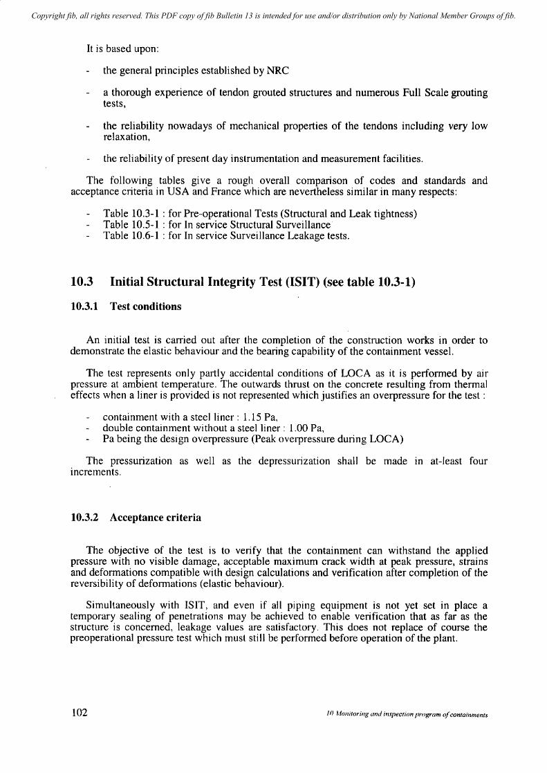
Copyright fib, all rights reserved. This PDF copy of fib Bulletin 13 is intended for use and/or distribution only by National Member Groups of fib.
It is based upon:
the general principles established by NRC
a thorough experience of tendon grouted structures and numerous Full Scale grouting tests,
the reliability nowadays of mechanical properties of the tendons including very low relaxation,
the reliability of present day instrumentation and measurement facilities.
The following tables give a rough overall comparison of codes and standards and acceptance criteria in USA and France which are nevertheless similar in many respects:
Table 10.3-1 : for Pre-operational Tests (Structural and Leak tightness) Table 10.5-1 : for In service Structural Surveillance Table 10.6-1 : for In service Surveillance Leakage tests.
10.3 Initial Structural Integrity Test (ISIT) (see table 10.3-1)
10.3.1 Test conditions
An initial test is carried out after the completion of the construction works in order to demonstrate the elastic behaviour and the bearing capability of the containment vessel.
The test represents only partly accidental conditions of LOCA as it is performed by air pressure at ambient temperature. The outwards thrust on the concrete resulting from thermal effects when a liner is provided is not represented which justifies an overpressure for the test:
containment with a steel liner: 1.15 Pa, double containment without a steel liner : 1.00 Pa, Pa being the design overpressure (Peak overpressure during LOCA)
The pressurization as well as the depressulization shall be made in at-least four increments.
10.3.2 Acceptance criteria
The objective of the test is to verify that the containment can withstand the applied pressure with no visible damage, acceptable maximum crack width at peak pressure, strains and deformations compatible with design calculations and verification after completion of the reversibility of deformations (elastic behaviour).
Simultaneously with ISIT, and even if all piping equipment is not yet set in place a temporary sealing of penetrations may be achieved to enable verification that as far as the structure is concerned, leakage values are satisfactory. This does not replace of course the preoperational pressure test which must still be performed before operation of the plant.
102 f(} Monitoring and inspection program of containments

Copyright fib, all rights reserved. This PDF copy of fib Bulletin 13 is intended for use and/or distribution only by National Member Groups of fib.
USA USA French French
Type of containment - Liner - Liner - Liner - no Liner
- Ungrouted - Grouted - Grouted - grouted - double wall
Initial Structural Integrity Test (l8IT) * Applied codes - 10 CFR50
- NRC Reg -RCCG 1998 Tome 2 guide 1.18 realisation - ASME-ACI 6000
Pressure I DBA pressure 1.15 1.15 1.15 1.00 (PA)
Concrete strains and temp-readings comparison with predicted values - Prototype
· Strains yes yes · Displacements yes yes
- Non Prototype · Strains no (or only if requested by yes (in standard areas)
designer) · Displacements yes yes
Acceptance criteria - elastic behaviour (90% recovery) - no visible damage yes yes
acceptable max crack width
- prestressing tendons force variation
no measurements -
Pre-operational Leakage Test
RCCG 1988 Tome 2 Applied code 10 CFR 50 Appendix J
realisation
Pressure value for leakage Pa Pa
rneasurementIDBA(Pa)
Acceptance lotal leakage 0,75 x 0,1 % for PWR 0,75 x 0,1 % 1%
rale in percentage of contained air per 24 h 0,75 x 0,5 % for BWR (+ leakage
(direct leakage) (direct test on outer containment)
leakage) (indirect leakage)
Table 10.3-1 - Initial structural Integrity Test (ISIT) and pre-operational pressure test Comparison of US, French and Japanese regulations
fib Bulletin 13: Nuclear containments
Japan
- Liner - Ungrouted
- - MITI Ordinance 62
1.125
yes yes
yes
yes
yes
-
MITI Ordinance 62 JEAG 4203
0.9 Pa
0.950.1 for PWR
0.9504-0.5% for BWR (direct leakage)
103
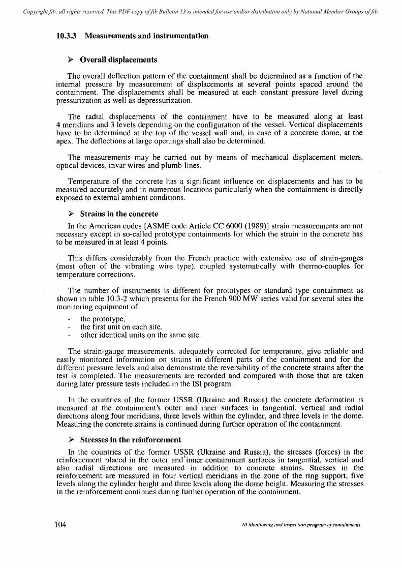
Copyright fib, all rights reserved. This PDF copy of fib Bulletin 13 is intended for use and/or distribution only by National Member Groups of fib.
10.3.3 Measurements and instrumentation
)0> Overall displacements
The overall deflection pattern of the containment shall be determined as a function of the internal pressure by measurement of displacements at several points spaced around the containment. The displacements shall be measured at each constant pressure level during pressurization as well as depressurization.
The radial displacements of the containment have to be measured along at least 4 meridians and 3 levels depending on the configuration of the vessel. Vertical displacements have to be determined at the top of the vessel wall and, in case of a concrete dome, at the apex. The deflections at large openings shall also be determined.
The measurements may be carried out by means of mechanical displacement meters, optical devices, invar wires and plumb-lines.
Temperature of the concrete has a significant influence on displacements and has to be measured accurately and in numerous locations particularly when the containment is directly exposed to external ambient conditions.
)0> Strains in the concrete
In the American codes [ASME code Article CC 6000 (1989)] strain measurements are not necessary except in so-called prototype containments for which the strain in the concrete has to be measured in at least 4 points.
This differs considerably from the French practice with extensive use of strain-gauges (most often of the vibrating wire type), coupled systematically with thermo-couples for temperature corrections.
The number of instruments is different for prototypes or standard type containment as shown in table 10.3-2 which presents for the French 900 MW series valid for several sites the monitoring equipment of:
the prototype, the first unit on each site, other identical units on the same site.
The strain-gauge measurements, adequately corrected for temperature, give reliable and easily monitored infolmation on strains in different parts of the containment and for the different pressure levels and also demonstrate the reversibility of the concrete strains after the test is completed. The measurements are recorded and compared with those that are taken during later pressure tests included in the lSI program.
In the countries of the former USSR (Ukraine and Russia) the concrete deformation is measured at the containment's outer and inner surfaces in tangential, vertical and radial directions along four meridians, three levels within the cylinder, and three levels in the dome. Measuring the concrete strains is continued during further operation of the containment.
)0> Stresses in the reinforcement
In the countries of the former USSR (Ukraine and Russia), the stresses (forces) in the reinforcement placed in the outer and t inner containment surfaces in tangential, vertical and also radial directions are measured in addition to concrete strains. Stresses in the reinforcement are measured in four vertical meridians in the zone of the ring support, five levels along the cylinder height and three levels along the dome height. Measuring the stresses in the reinforcement continues during further operation of the containment.
104 10 Monitoring and inspection program of containments
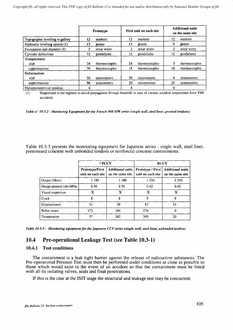
Copyright fib, all rights reserved. This PDF copy of fib Bulletin 13 is intended for use and/or distribution only by National Member Groups of fib.
Prototype First unit on each site Additional units on the same site
Topographic levelling in gallery 12 markers 12 markers 12 markers
Hydraulic levelling system (1) 13 points 13 points 9 J)oints
Foundation slab diameter (1) 2 invar wires 2 invar wires 2 invar wires
Cylinder deflections 12 pendulums 12 pendulums 12 pendulums
Temperature
slab 24 thermocouples 24 thermocouples 3 thermocouples
superstructure 70 thermocouples 18 thermocouples 18 thermocouples
Deformation slab 50 strain meters 50 strai n meters 4 strainmeters
superstructure 96 strainmeters 20 strai nmeters 20 strainmeters
Dynamometers on tendons 4 4 0 (1) Suppressed in the eighties to avoid propagation through baseslab in case of corium accident (experience from TMI
accident)
Table flO 10.3-2 - Monitoring Equipment/or the French 900 MW series (sillgle wall, steel liller, grouted tendons)
Table 10.3-3 presents the monitoring equipment for Japanese series: single wall, steel liner, prestressed concrete with unbonded tendons or reinforced concrete containments.
~PCCV RCCV
Prototype/First Additional units Prototype I First Additional units unit on each site on the same site unit on each site on the same site
Output (Mwe) 1.180 1.180 1.356 1.356
Design pressure (abs MPa) 0.50 0.50 0.42 0.42
Visual inspection X X X X
Crack 8 8 9 9
Displacement 51 59 87 53
Rebar strain 172 184 276 0
Temperature 57 242 309 20
Table 10.3-3 - Monitoring equipment/or the Japallese CCV series (single wall, stee/liner, unbonded telldo,,)
10.4 Pre-operational Leakage Test (see Table 10.3-1)
10.4.1 Test conditions
The containment is a leak tight barrier against the release of radioacti ve substances. The Pre-operational Pressure Test must then be performed under conditions as close as possible to those which would exist in the event of an accident so that the containment must be fitted with all its isolating valves, seals and final penetrations.
If this is the case at the ISIT stage the structural and leakage test may be concurrent.
fib Bulletin 13: Nuc:lear containmellts 105
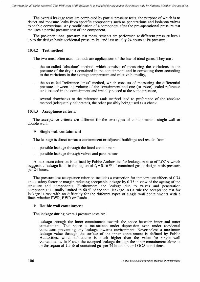
Copyright fib, all rights reserved. This PDF copy of fib Bulletin 13 is intended for use and/or distribution only by National Member Groups of fib.
The overall leakage tests are completed by partial pressure tests, the purpose of which is to detect and measure leaks from specific components such as penetrations and isolation valves to enable corrections. Any modification of a component after the pre-operational pressure test requires a partial pressure test of the component.
The pre-operational pressure test measurements are performed at different pressure levels up to the design basic accidental pressure Pa, and last usually 24 hours at Pa pressure.
10.4.2 Test method
The two most often used methods are applications of the law of ideal gases. They are:
the so-called "absolute" method, which consists of measuring the variations in the pressure of the dry air contained in the containment and in correcting them according to the variations in the average temperature and relative humidity,
the so-called "reference tanks" method, which consists of measuring the differential pressure between the volume of the containment and one (or more) sealed reference tank located in the containment and initially placed at the same pressure,
several drawbacks to the reference tank method lead to preference of the absolute method (adequately calibrated), the other possibly being used as a check.
10.4.3 Acceptance criteria
The acceptance criteria are different for the two types of containments: single wall or double wall.
~ Single wall containnlent
The leakage is direct towards environment or adjacent buildings and results from
possible leakage through the lined containment,
possible leakage through valves and penetrations.
A maximum criterion is defined by Public Authorities for leakage in case of LOCA which suggests a leakage limit in the region of fa = O. J 6 % of contained gas at design basis pressure per 24 hours.
The pressure test acceptance critelion includes a correction for temperature effects of 0.74 and a safety factor or margin reducing acceptable leakage by 0.75 in view of the ageing of the structure and components. Furthermore, the leakage due to valves and penetration components is usually limited to 60 % of the total leakage. As a rule the acceptance test for leakage is met with no difficulty for the different types of single wall containments with a liner. whether PWR, BWR or Candu.
~ Double wall containment
The Jeakage during overall pressure tests are:
106
leakage through the inner containment· towards the space between inner and outer containment. This space is maintained under depression even under accidental conditions preventing any leakage towards environment. Nevertheless a maximum leakage value through the surface of the inner containment is defined by Public Authorities, which of course is much higher than the value for single wall containments. In France the accepted leakage through the inner containment alone is in the region of 1.5 % of contained gas per 24 hours under LOCA conditions,
J 0 Monitoring and inspection program of containments
Copyright fib, all rights reserved. This PDF copy of fib Bulletin 13 is intended for use and/or distribution only by National Member Groups of fib.
possible direct leakage through valves and penetrations, which in France is limited to around 10 % of the total leakage.
The correction of 0.74 for temperature is applied to the direct leakage, but not for leakage through the concrete structure as condensation of the steam through the concrete in case of an accident is an important safety factor.
However the additional safety factor reducing by 0.75 the accepted leakage during test is maintained for both types of leakages in view of ageing of the structures.
In the case of a double containment, testing of the external containment is permanently checked by the ventilation system ensuring a slight negative pressure between inner and outer containments.
It is observed that for the double-wall containments with no liner from the French PWR program, the criteria have systematically been met, but a significant variation in leakage rate through the containment is observed depending on the concrete composition.
10.5 In service Surveillance of the structural Integrity (see table 10.5-1)
10.5.1 The objective of in-service surveillance: Ageing management
The objective of in-service surveillance is to provide sufficient information during the entire operational life of the plant to ensure that ageing does not adversely affect the plant's ability to withstand conditions, nonnal, accidental, or extreme, to which it may be subjected.
With regard to the civil works and particularly the containment, the main degradation process concerns:
the concrete: cracking, spalling, excessive strains, lowering of resistance. These factors are in relation with the stresses in the concrete, the quality of the work, the chemical and physico-chemical process in the concrete, and the environmental conditions,
the metallic parts: liner, reinforcement, prestressing, penetrations for which the main degradation mechanism is corrosion, related to wetting or chemical agents.
The in-service surveillance includes visual inspection, monitoring, testing of the materials and pressure tests.
The Ageing Management System (AMS) will collect all the obtained information, evaluate the effects of degradation, propose specific monitoring and testing in relation with observed degradation and propose maintenance and remedial actions.
The knowledge of the rate of evolution of the ageing process and possible remedial actions obtained from AMS is necessary to predict the life duration of the plant and its possible extension [J.P. Mc Fariane (1999)].
Important aspects of AMS for concrete containment buildings are covered in technical documents published by IAEA [IAEA - TECDOC - 1025 (1998)]
As prestressing is an important and sensitive component for concrete containments, the following two paragraphs present the specifics of lSI for unbonded and cement grouted tendons.
fib Bulletin 13: Nuclear containments 107
Copyright fib, all rights reserved. This PDF copy of fib Bulletin 13 is intended for use and/or distribution only by National Member Groups of fib.
10.5.2 Prestressed concrete containments with unbonded tendons
The main justification for the use of unbonded tendons rather than tendons which are cement-grouted has been that there is the possibility of a direct in-service examination of the tendons.
In addition ungrouted tendons can be replaced if they are found to be defective on examination.
In the USA, where ungrouted tendons have been used for most prestressed concrete containments, the inservice inspection of the ungrouted tendons is carried out in accordance with the NRC Regulatory Guide 1.35 In-service inspection of ungrouted tendons in prestressed concrete containment structures (January 1976).
As stated in the Regulatory Guide 1.35 the in-service inspection of ungrouted tendons includes the following:
1) Selected tendons should be periodically subjected to lift-off or other equivalent tests to monitor loss of prestress.
2) The physical condition of the tendon material should be checked on some tendons removed for testing.
3) Tendon anchorage assemblies of all tendons examined in accordance with 1 and 2 should be visually examined.
The guide specifies in great detail the number of tendons to be inspected and the procedure for testing.
The in-service structural Integrity Surveillance program according to NRC regulations does not require any particular structural observation or measurement during the in-service pressure tests perfonned solely to control leak-tightness.
In the Ukraine, according to standard documents, in-service inspection of ungrouted tendons is executed as follows.
Every year, during the first three years of operation, the following measures are carried out:
visual inspection: moisture control of tendons and anchor blocks enclosure, lubrication layer continuity control, break control of wires, corrosion control of anchor's elements and wires,
control of tension force on 20 tendons in the cylinder and 8 tendons in the dome,
full unloading followed by prestressing of 2 tendons in the cylinder and one tendon in the dome, in which the tension force was controlled.
After four years of operation and in addition to these measures, at four yearly intervals the dismantling of 2 tendons in the cylinder and one tendon in the dome shall be carried out.
The extent of this work must be increased if defects or average losses of tension force of more than 15% take place. If additional control data corresponds with such results, it is necessary to test 100% of tendons. After re-tensioning the tendons with force loss more than 15%, control will be repeated. If a tension loss over 10% is observed within 24 hours, the tendon must be replaced.
In the U.K. the extensive experience gained from PCPVs has been reviewed and adapted for PCCVs [J.P. Me Farlane (1996)].
108 /0 Monitoring and inspection program of containments

Copyright fib, all rights reserved. This PDF copy of fib Bulletin 13 is intended for use and/or distribution only by National Member Groups of fib.
10.5.3. Prestressed concrete containments with cement-grouted tendons
When cement-grouted tendons are chosen, priority has been given to the best possible corrosion protection of the tendons and the best possible structural behaviour of the containment, (especially for overloading conditions) with respect to size of cracks and consequently to safety against leakage. On the other hand, there is no possibility of a direct inservice examination of the tendons.
The in-service inspection of prestressed containments with cement-grouted tendons has to be done indirectly by measurements and observations, which includes the following:
1) Inspection including crack observation in connection with periodical pressure testing. Particular attention is given to stress concentration at penetrations, comers, etc. Substantial loss of prestress could be expected to lead to local cracks at such locations in case of pressurization.
2) Strain gauges (usually vibrating wire type) embedded in concrete and associated with temperature sensors are used extensively and have proved to be reliable, precise and very informative for evaluation of the creep strains in concrete and the corresponding losses in prestressing force.
The monitoring data processing system and corresponding results are automatized in the latest French containments enabling information on strains in numerous parts of the containment to be obtained from the time of the installation of the strain gauges in a clear graphical format.
3) Deformation and strain measurements in conjunction with periodic pressure testing are systematical in the French practice in accordance with RCCG (1988). This method enables verification of the elastic behaviour of the containment in the course of the pressure loading, and comparison of the Ineasurenlents during sLlccessive pressure tests.
This is unusual in the American practice where structural deformation measurements and visual inspection during pressure tests are prescribed only if data from embedded instrumentation are questionable, in accordance with USNRC Reg. Guide 1.90 (August 1977).
fib Bul/etin 13: Nudear containments 109

Copyright fib, all rights reserved. This PD
F copy of fib Bulletin 13 is intended for use and/or distribution only by National M
ember G
roups of fib.
_ I Origin of code o Type of containment I -with liner
USA - with liner
- un grouted tendons - grouted tendons Applied code I - 10 CFR 50 - IO CFR 50
- NRC Reg Guide 1.35 - NRC Reg Guide 1.90
France - liner or no liner -Nouted tendons RCCG 88 Tome 2 (Realisation)
Japan - with liner - ungrouted tendons Guideline for assurance of structural integrity of concrete vessel and in-service inspection during plant life (tentative) JEAG4203
Inspection methods Based on inspection of a I Two possible alternatives depending on the reliability of I Based on :
~ >
[ 3. ~
Frequency of tests
~ I Acceptance criteria
~. ;:;: 3. ~ ::: ~ ~ ~ ~ 8 ~ e. ::: :: § ~
selection of tendons of each type (about 4% of total number) - visual (anchorage)
I instrumentation I - Measurement by
- lift off or equivalent - removal of one tendon of
each type for testing steel and grease
Alternative A Alternative B
- Monitoring by strain Pressure tests at least at DBA metres and temp. sensors level (Pa) and comparison of to predict losses 111 tendon the deformations of the force containment with ISIT
- completed hy visual measurements inspection and lift off tests on some tendons left ungrouted.
instrumentation of strains in concrete and evaluation of the reSUlting losses in prestressing force.
- Periodical pressure tests at DBA level (Pa) induding complete instrumentation measurements and visual inspection.
- Monitoring of some tendons left ungrouted (on prototypes only)
Concrete: - Visual inspection of overall vessel with respect to
cracks, degradation and defect. - detailed visual inspection for selected areas with
respect to crack length, extent and circumstance of degradation and defect,
- corrosion of rebar
Tendon: - Visual inspection of tendon and anchorage lift off
or equivalent - Removal of sample tendon for testing tensile
strength, ~ding~treng1h and elongation. I, 3 and then every five years Instrumentation readings - I year after ISIT: no I - _Frequent instrumentation Basically 1,3,5 year after ISIT, and after that
conduct on-need-to-do-basis in view of previous test results. frequency can be reduced if the same type of plant exists on the same site.
after IS IT. eveiy 2 months from pressure. No pressure test associated installation to first - 6 and I 1 years after IS IT :
1.15 Pa. with the structural inspections. surveillance tests. Then every 6 months. - Every 5 years at Pa.
- Prestress force within the predicted limits
- Not more than one tendon defecti ve in total sample popllation as long as adjacent tendons acceptable
- Tensile failure tests on removed tendon higher than UTS
Inspection tests at I, 3 and every 5 years after ISIT. No pressure test associated. Verification that the During pressure tests: evaluated prestress forces arc - limited increase of within the predicted region. deformations- compared as well as the forces of with ISIT (less than 5%) tendons left ungrouted. - limited increase of cracks.
Verification that the forces in tendons left ungrouted are acceptable.
measurements (continuous since installation for the latest containments)
- Pressure tests at : . first shut-down for refueling . every 10 years
- Permanent observation of Concrete: instrumentation measurements - If newly developed cracks, degradation and to check that with time : defects are found., the structural integrity of vessel
no abnormal strain is must be assured by investigating the cause and observed. taking proper remedial actions if required reSUlting prestress forces are Tendon: within predicted values. - Prestressing force beyond the effective design
- Observation of elastic force. Tendon free from corrosion and no physical behaviour during pressure defect, and mechanical properties satisfy the tests and limited change in specified values. deformations. Anchorage free from corrosion, no local damage
and no unusual cracks observed in its peripheral concrete.
Table 10.5-1 -In service structural surveillance: comparison 0/ USA, French and Japanese regulations
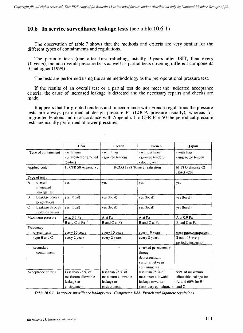
Copyright fib, all rights reserved. This PDF copy of fib Bulletin 13 is intended for use and/or distribution only by National Member Groups of fib.
10.6 In service surveillance leakage tests (see table 10.6-1)
The observation of table 7 shows that the methods and criteria are very similar for the different types of containments and regulations.
The periodic tests (one after first refueling, usually 3 years after ISIT, then every 10 years), include overall pressure tests as well as partial tests covering different components [Chataigner (1999)].
The tests are performed using the same methodology as the pre-operational pressure test.
If the results of an overall test or a partial test do not meet the indicated acceptance criteria, the cause of increased leakage is detected and the necessary repairs and checks are made.
It appears that for grouted tendons and in accordance with French regulations the pressure tests are always peJformed at design pressure Pa (LOCA pressure usually), whereas for ungrouted tendons and in accordance with Appendix I to CFR Part 50 the periodical pressure tests are usually performed at lower pressures.
USA French French J~.pan
Type of containment - with liner - with liner - without liner - with liner
- ungrouted or grouted - grouted tendons - grouted tendons - ungrouted tendon
tendons - double wa11
Applied code 10 eFR 50 Appendix J ReCG 1988 Tome 2 realisation M ITI Ordinance 62
JEAG 4203
Type of test:
A overall yes yes yes yes
integrated
leakage test
B Leakage across yes (local) yes (loral) yes (local) yes (local)
penetrations
e : Leakage through yes (local) yes (local) yes (local) yes (local)
isolation valves
Maximum pressure A at 0.5 Pa A at Pa A at Pa A at 0.9 Pa
Band C at Pa Band C at Pa Band C at Pa Band C at Pa
Frequency
- overall tests every 10 years every 10 years every 10 years every periodic inspection
- type Band e every 2 years every 2 years every 2 years 2 out of 3 every
periodic inspection
- secondary -- -- checked permanently
containment through
depressurization
systems between
containments
Acceptance criteria Less than 75 % of less than 75 % of less than 75 % of 95% of maximum
maximum allowable maximum allowable maximum allowable allowable leakage for
leakage to leakage to leakage towards A, and 60% for B
environment environment secondary containment andC
Table 10.6-1 - In service .wrveillance leakage tests - Comparison USA, French and Japanese regulations
fib Bulletin 13: Nuclear containments 111
Copyright fib, all rights reserved. This PDF copy of fib Bulletin 13 is intended for use and/or distribution only by National Member Groups of fib.
10.7 Some typical results of structural deformation obtained by monitoring
10.7.1 Strain measurements during construction and prestressing
» The strains and deformations in the structure during the construction phase and before prestressing result from:
- shrinkage, whether thermal or hygral, - strains due to stresses resulting from the dead load of structures, - deformations and subsidence of the basemat due to soil reactions and settlement, - tilting due to differential soil settlement.
The overall defOImations and settlements are measured mainly by topography and pendulum measurements while the strains are measured usually by strain gauges embedded in the concrete.
~ The prestressing forces to which the structure is progressively subjected to during the prestressing phase are internal forces and membrane forces for standard sections but with bending effects in junction areas and close to penetrations. The strains resulting from direct stresses and from the Poisson effects are measured mainly by strain gauges embedded in the concrete or fixed on re-bars both in standard areas and in particular parts of the containment but especially in the vicinity of large penetrations (equipment hatch).
The strain gauges are associated with thermocouples so as to allow the necessary temperature corrections to be made. "
Some results from an automatic remote monitoring system in Civaux2 unit used since the beginning of pouring of the concrete [Roy (1997)] show the precision and the reliability of the system.
In order to enable a correct interpretation of results during the entire life of the plant it is preferable to perfOIm the first monitoring measurements as early as possible during the construction stage (initial measurement).
10.7.2 Strain measurements during ISIT
During pressure tests (for instance at IS IT) deformations of the structure are measured continuously as the pressure increases and then decreases, the duration of the test being approximately one week.
It is regularly observed, for instance [Setogawa (1993)] and also [T. Kuroda (1999)], that in standard areas the reversibi lity of strains is practically complete showing an elastic behaviour of the prestressed structures. A very limited residual strain due to reverse creep during unloading and reloading may be observed. It also appears that for reinforced concrete containments [Kituchi (1997)], the strains are also perfectly reversible which is in line with the design criteria requiring stresses in rebars to remain within the elastic limit. After adjustment of the modulus of elasticity to that measured, the deformations measured and calculated are nearly always in excellent agreement.
112 10 Monito/'iny, and inspection program oj containments
Copyright fib, all rights reserved. This PDF copy of fib Bulletin 13 is intended for use and/or distribution only by National Member Groups of fib.
10.7.3 Modulus of elasticity of the concrete measured from pressure tests
The modulus of elasticity of the concrete is usually estimated from code rules and controlled by testing both before construction starts and also during construction. The ISIT pressure test can be considered as a full-scale measurement of the modulus of the concrete and of the Poisson ratio by interpretation of deformations in standard sections in the tangential and vertical directions. The modulus measured during the pressure test is close to a short-term modulus but usually considered slightly lower than the instantaneous modulus adopted, for instance in seismic design.
One may observe [F. Martinet, (1997)], that between successive pressure tests for each containment usually at ISIT, 3 years after ISIT and then 10 years later, the elastic moduli vary very little which indicates the absence of degradation of the structure and prestressing with time.
The calculated moduli for the 34 identical containment units presented in the quoted document correspond to a concrete with a specified characteristic compression strength at 28 days of 36 MPa. One can observe a variation in elastic moduli from 28 000 MPa to 44 000 MPa depending on the type of mix and aggregates. It is quite clear that the stresses in the liner and penetrations in relation to short term and long term concrete deformations as well as the losses in tendon forces will vary slightly from one unit to the other. .
The stresses in the concrete will only differ very little from one containment to the other as the difference will mainly result from different losses in prestressing force due to elastic deformation of the concrete and later to creep and shrinkage effects.
It is nevertheless advisable to test the mechanical properties of the concrete from the very beginning of construction for sholt term modulus as a minimum as short and long term modulus are inter-related.
10.7.4 Long term strain measurements
Strains in concrete are usually measured regularly by strain gauges:
to check the prestressing losses due to long term concrete deformation so as to ensure that adequate margins are maintained throughout the life of the containment,
to check that no abnormal result is observed which could show a degradation of the concrete, for instance an increase in the rate of creep, whether local or general or conversely expansion of the concrete.
Several articles have presented examples of long term strain measurements [Costaz (1989)] or [Tamura (1991)] and also the consequences on the prestressing force losses: [XU Yao Zhang (997)], [E. Martinet (1997)].
When tendons are unbonded, the losses in prestressing are directly measured (for instance by lift-off) but the information is complemented by the strain measurements in concrete in order to obtain a better understanding of the respective effects of concrete deformations and steel relaxation on the prestressing losses [V. Maliavine (1997)], [Yo Klymov (1997), Y. Klymov (2000)].
fib Bulletin 13: Nuc:/ear containments 113
Copyright fib, all rights reserved. This PDF copy of fib Bulletin 13 is intended for use and/or distribution only by National Member Groups of fib.
10.8 Ageing Management after decommissioning - Dismantling
As mentioned in paragraph 4.6.6, adequate surveillance must be maintained after decommissioning of the plant.
As a rule, dismantling is not performed shortly after decommissioning because operations are simplified and it is advantageous if work is deferred until the radioactivity of the most irradiative radio-elements inside the containment or inside circuits and main components in the containment are allowed to decay naturally with time. The containment is generally used as a temporary waste area so that a specific surveillance program (which will include visual inspection, monitoring and testing of materials) should be maintained until dismantling. Repair work is performed when necessary.
DismantJing of the containment is performed under strict control. For prestressed containments, detensioning in particular has to be carefully processed in order to release progressively the elastic energy stored in the un bonded tendons.
114 10 Monitoring and inspection program of the containment

Copyright fib, all rights reserved. This PDF copy of fib Bulletin 13 is intended for use and/or distribution only by National Member Groups of fib.
11 Possible incidental events requiring particular care in design, construction and monitoring of NPP containments
11.1 Preamble Two major NPP accidents have occurred in the past:
Three Mile Island PWR in 1979 in Pennsylvania (USA) Chernobyl RBMK in 1986 in Ukraine
Such accidents resulting mainly from deficiencies in equipment aggravated by human operating errors have led to an in-depth international analysis leading to a reconsideration of all safety aspects related to NPP's. These considerations are beyond the scope of this state-ofart report although it may be stressed that the Three Mile Island containment acted perfectly throughout the accident avoiding any release of radioactivity into the environment. The Chemobyl incident is different as an overall leak tight containment did not exist (which in this particular accidental case might anyway not have been sufficient to avoid dramatic consequences). The object of this chapter is limited to listing some events or minor incidents in relation to the containment structures which have been observed during construction, inspections or assessments of the plant and have been satisfactorily taken care of (upgrading of the containment).
11.2 Change in design loads Re-evaluation of seistnic input -+ verification that design remains adequate Re-evaluation of risks due to flooding -+ veri tication that the possible water inlets
can be adequately sealed after closing the plant
Re-evaluation of effects of freezing on water inlet flow and insulation.
11.3 Prestressing tendons Losses of prestressing force higher than expected:
result usually from excessive steel relaxation which is practically never the case in today's very low relaxation wires. They may also be due to higher than expected long term deformations of concrete (high stresses, particular nature of aggregates)
o when unbonded tendons are used, it may be necessary to resort to retensioning, o when tendons are grouted, it is preferable to provide very low relaxation
prestressing steel and to check and evaluate the modulus and creep in concrete, and to design the prestressing with adequate margins prior to construction.
Local failures (most often on older prestressing systenls)
o anchor head failures due to deficiencies in design of the head, o broken wires due to corrosion and in particular hydrogen stress cracking (for
instance due to electric cell between steel and zinc of the sheathes), o corrosion of tendon due to ageing of the grease protection.
11.4 Liner and liner plates
Corrosion has been observed and repair has been necessary on several containment liners, due to degraded coatings, particularly most often in specific zones SUbjected to condensation such as transition zones between metal and concrete.
Buckling of the liner in relation to the anchorage with the concrete.
fib Bulletin J 3: NlIclear containments 115
Copyright fib, all rights reserved. This PDF copy of fib Bulletin 13 is intended for use and/or distribution only by National Member Groups of fib.
11.5 Design problems Leak tightness in junction areas with main penetrations (such as the equipment hatch) and design of the leak tight joint,
specific design incidents observable during construction or initial pressure test of the containment with regard to high stresses and high strength prestressing tendons in a thin shell structure such as :
o cracks in areas of discontinuity visible during the pressure test or appearing during the prestressing sequences,
o exfoliation in the shell (dome) due to insufficient shear re-bars in the concrete [Y.Klymov (2000)]
o local failures in compression (for instance in anchorage zone).
Differential settlement of foundations with effects on piping connections.
11.6 Leak tightness of the containment Where a steel liner exists, the leak tightness is dependent on the imperviousness of the 1 iner which may be affected by:
o corrosion, o faults in the welding between plates (to be controlled);
when the containment is double-walled with no liner, although any leakage is collected between inner and outer containment, the leak tightness of the inner containment is specified and pressure tested.
It may be affected by:
o the porosity of the concrete (minor effect), o local cracks due to shrinkage during construction between areas of different
rigidity, o reduction of leak tightness between successive concrete lifts (taken care of by
grouting during construction), o local cracks in areas of discontinuity for instance close to the equipment hatch
(local coating can be applied to this particular area if required).
11.7 Evolution of concrete with time Although it is extremely rare considering the care involved in ensuring the quality of the mix, alkali-reaction or other phenomena leading to concrete expansion with time which may be accompanied by a degradation of concrete strength has been observed in some nuclear power plant buildings. This does not appear to have affected any containment to our knowledge.
Evolution of deformations
In some prestressed containlnents creep has appeared higher than expected from regulations and on site testing. This required checking that design criteria remained satisfied.
116 I J Possible incidental events requiring parTicular care
Copyright fib, all rights reserved. This PDF copy of fib Bulletin 13 is intended for use and/or distribution only by National Member Groups of fib.
References
ASME code Section 3 Division 2 (1989). ACI code for PCCV and PCRV. Article CC 6000
Axcell, 2001, Containment cooling by water film, The Nuclear Engineer, Vol. 42, Number 1
Basu, 1999, Containment construction using HPC (AEB) India. Proceedings of seminar on containments of nuclear reactors in conjunction with ISth SMIRT, Seoul.
Chataigner, Granger, Touret, 1999. Containlnent leakage under accident conditions. Proceedings of seminar on containment of Nuclear Reactors in conjunction with ISth SMIRT, Seoul.
Costaz, 1992, Le beton hautes performances (HPC), RON N° 4 Costaz, (EDF Septen), IS-22 Nov. 1992, Infrastructures for energy, Keynote, 1FT A -
Seminar on Civil Engineering and Architecture. Costaz, Picaut, Chataigner, 1989. Delayed Phenomena Analysis froln French PWR
900 MW containment. Monitoring comparison with foreseen design values. SMIRT 10. Danish, Hansen, Liersch, Peter, 1997- Testing of a concrete containment model coated
with a composite liner. SMIRT 14 - Vol. S Div. H concrete structures. HW/2. Danisch, Hansen, 1999, Status report on German containment composite liner research.
Proceedings of seminar on containment of Nuclear Reactor in conjunction with ISth SMIRT, Seoul.
De Larrare, Ithuralde, Acker, Chauvel, 1990 HPC for NPP, 2nd int. conf. on utilisation of HSC, Berkeley, ACISP.
FIP - Federation Internationale de la Precontrainte, state-of-art report: Design and construction of prestressed concrete reactor vessels, June 1978.
Granger, Labbe, 1997. Mechanical and leak tightness behaviour of a containment mock-up under severe accident - SMIRT 14 - Vol. S Div. H concrete structures. HW/l
Guinet, Decelle, Lancia, Barre, 1997. Design and erection of a large mock-up of containment under severe accident conditions - SMIRT 14 - Vol. S Div. H concrete structures. HW/3.
Hessheilner, Pace, Klamerus, Matsumoto, Costello, 1997. Instrumentation and testing of a PCCV model -. SMIRT 14 - Vol. S Div. H concrete structures. H03/4.
IAEA - TECDOC-J 02S, June 1998. Assessment and management of ageing of major nuclear power plant components important to safety: concrete containment buildings
Irving, Hinley, and Palfrey: The Design, Analysis and Testing of the 1110 Scale Model of the Sizewell B Containment Building, International Conference on Structural Design For Hazardous Loads, Institution of Structural Engineers, Brighton, UK, 17-19 April 1991.
Jolivet, Richli, 1977. A Seismic Foundation Systetn for Nuclear Power Stations, SMIRT 4, vol. K (b).
Kikuchi, Kobanashi, Ichizono, 1997. SIT -Kashiwazahi Kariwa - RCCV. Structural Integrity test of reinforced concrete containment at Kashiwazaki-Kariwa. SMIRT 14. Vol. S Div. H concrete structures. H03/S - H03/6.
Klynl0v, (State Research Institute of Building Construction, Kiev), 1997. Monitoring of stressed-strained state and forces in cables of prestressed containment shells of NPPs. Joint Wano/OECD-NEA. Workshop, Civaux, Poitiers, France.
KlytTIov, 2000 (State Research Institute of Building Construction). Results and Problems of Monitoring of Prestressed Containment of Nuclear Power Plants. OECD-NEA. Workshop, Tractebel-Brussels, Belgium.
Kuroda et aI, 1993. Recent advances in concrete containnlent vessels in Japan, Nuclear Engineering and Design 140.
Kuroda, Hasegawa, 1999. Recent topics on concrete containtnent vessels in Japan verification of SIT and assurance of safety margins
h Japan Proceedings of seminar on
contail11nent of Nuclear Reactors in conjunction with 1St SMIRT, Seoul. Libmann, 1997. Elements de SGrete Nucleaire - IPSN. Published by Lavoisier, France.
fib Bulletin 13: Nudea,. containments 117
Copyright fib, all rights reserved. This PDF copy of fib Bulletin 13 is intended for use and/or distribution only by National Member Groups of fib.
Maliavine, 1997. Atom Energoproject Russian Federation. Prestress losses in containments of VVER 1000 Units. Joint Wano/OECD-NEA. Workshop, Civaux, Poitiers, France.
McFarlane, Smith, Davies, Millustry. In-service monitoring of AGR and PWR Nuclear Safety related Structures in the UK, Institution of Nuclear Engineers, September 1996, Cambridge, UK.
McFarlane, Smith. Plant Life Management. European Commission, Directorate General, FISA 99 Symposium, Luxembourg.
Martinet, Guinet, Roussel, Granger, 1997. Prestress losses in NPP containments: the EDF experience. Joint Wano/OECD-NEA. Workshop, Civaux, Poitiers, France.
OECD-NEA Nuclear Regulation, January 200 1-: Regulatory aspects of life extension and upgrading of MPPs. CNRA Special Issues Meeting 2000 Report.
Picaut, Sidaner, Pastor, Lorteau, 1991, The dome of Daya Bay containment, design and construction, SMIRT 11.
Proceedings of seminar on containtnent of Nuclear Reactor in conjunction with 15th SMIRT, Seoul.
RCCG - Design and construction rules for civil works of PWR Nuclear Islands Roy, Guinet, Barre, 1997. Concrete monitoring analysis during the prestressing of a
containment and comparison with foreseen design values - SMIRT 14. Vol. 5 Div. H concrete structures. HOI 12.
Saito, H. et aI, 1989, Experimental study on RCCV of ABWR plant. SMIRT 10. Setogawa, Sakarai, Funokoshi, Yemaguchi, Koike, Kamei and Hagro, 1993. Structural
Integrity tests of prestressed concrete containment vessels at Ohi NPP. SMIRT 12. Vol H. SFEN - November 1995, Proceedings on International Conference on the EPR Project SMIRT 14 - August 97 Vol. 5 Div. H concrete structures. - H 04/3 PSA of typical
900 MW French nuclear containment. Grangier, Chataigner. Smith L.M., Taylor M.F., 1997, The Long term In-Service Performance of Corrosion
Protection to Prestressing Tendons in AGR PCPVs, Joint Wano / OECD-NEA Workshop, Civaux, Poitiers, France.
Smith, De Marneffe, Mathet, Contri, November 2000, civil Engineering Instrumentation on Nuclear Power Plants - An International Perspective, Institution of Nuclear Engineers
Tamura, Watanabe, Kato, Yamaguchi, Koike, Komatsu, 199]. A delayed Phenomena evaluation of prestressed concrete containment vessel at Tsuruga Unit 2 power station. SMIRT 11.
UNSRC Reg. guide 1.35 lSI ungrouted tendons Jan. 76 USNRC Reg. guide 1.90 lSI grouted tendons Aug. 77
Xu Yao Zhang, 1997. Containment structure monitoring and prestress losses. Experience from Daya Bay NPP. Joint Wano/OECD-NEA. Workshop, Civaux, Poitiers, France.
118 References
Copyright fib, all rights reserved. This PDF copy of fib Bulletin 13 is intended for use and/or distribution only by National Member Groups of fib.
Annex
to Bulletin 13
(CD-ROM 'Annex Bulletin 13')
General data on nuclear power plant containments built since 1972
• List of main data for some 160 NPPs • Data sheets ( and 'mostly sketches)
Detailed information on some typical recent containments
• Type PWR: Tricastin, Civaux and Genkai • Type BWR/ABWR: Oskarshamn, Kashiwazaki
• Type PHWR: Kaiga
June 2001

Copyright fib, all rights reserved. This PDF copy of fib Bulletin 13 is intended for use and/or distribution only by National Member Groups of fib.
The general data on nuclear power plant containments built since 1972 are presented in the attached CD-ROM (' Annex Bulletin 13 ') in form of
120
a table of data for some 160 NPPs: Country - Name ofNPP - Type -Nuclear system supplier - Power - Number of units - First Power - Begin of construction - Design pressure - Containment type - Liner (as table 1.3-1 on pages 3-4)
data sheets an example of which is presented on page 121. The information specifies for each containment: the name, country, owner and supplier of the plant, the type and power of the plant, the construction and first power dates, and a description of the main characteristics of the containment: • dimensions and type of containment • construction materials • prestressing characteristics • main design values Where available a sketch of the containment is also given on the data sheet.
a further file presents detailed information on six containments considered as representative for different types of nuclear power plants. The information includes for each of these NPP the following fields: generalities - geometry of containment -constitutive materials - main design loads - codes, standards and criteria -instrumentation. Presented are
• three PWR containments: Tricastin (France), Civaux (France), Genkai (Japan) • two BWR / ABWR containments: Oskarshamn (Sweden), Kashiwazaki (Japan) • one PHWR containment: Kaiga (India)
Annex: General data rill 1I1'{J containments
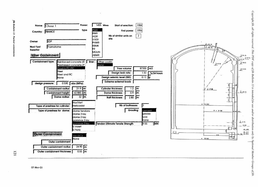
Copyright fib, all rights reserved. This PD
F copy of fib Bulletin 13 is intended for use and/or distribution only by National M
ember G
roups of fib.
'::h a-bo .,
~ .... ~ , I· ~
...... N ......
Name IChooz 1 Power: I 1455 Mwe Start 01 erection: 119841
Country: IFRANCE type ~ First power 119961
IT] Owner IEDF
Nucl5yst Supplier
IFromotome
~lql1~r.··~tiJ~lqml"!·1
L
Containment type:] IReinforCed concrete (R l!!n~r: Prestressed concrete P Ie _.
,teel ,teel ond RC
None
design pressure:' r--O.530'( abs (MPa);
I Coo~""""ad,,,1 I '. 2 .... 1 .... 9 .. i.~ .. i i Con,alnrnent h~lgt'!t. 16:?8~q; m
i , Dome radius:. .~? m,
Type of prestress for cyUnder:·
Type of prestress for dome:
, rp. ______ 1II!'
11-'t"(:.j~'"taln'\W'inl~ ~
711!J-"::~::nmenl' j"" • Outer containment radius I 24.90 F
Outer containment thickness I 0.55 F
OHevr-Ol
Nb 01 similar units on site
ther cootin Q1i-r.~·
Free volume J'873OO I m3
DeSign leak rate: ~ '~%~/~24~h-o-ur-s
DeSign seismic level (SSE) I 0.12 g'
I Extreme external loads I Cylinder thickness! ~.2. F
Dome thickness ~ F Raft thickness rm F
Nb of buHresses
I Grouting
-.J~t6 6~
1U6~
__ ~L..1?~
------------------_·~I~
R - 21.90 )11'.!'!I!lL
o
I I I r-' -. -._. _. -. hlJ:-i f·
It ~O.90
. .k..vo ~--
.!I::.o..l.!L