research article modeling and simulation of flexible...
TRANSCRIPT
Research ArticleModeling and Simulation of Flexible TransmissionMechanism with Multiclearance Joints for UltrahighVoltage Circuit Breakers
Fangang Meng Shijing Wu Fan Zhang Zenglei Zhang Jicai Hu and Xiaoyong Li
School of Power and Mechanical Engineering Wuhan University Wuhan 430072 China
Correspondence should be addressed to Shijing Wu 76811886qqcom
Received 20 April 2015 Accepted 3 August 2015
Academic Editor Salvatore Strano
Copyright copy 2015 Fangang Meng et al This is an open access article distributed under the Creative Commons Attribution Licensewhich permits unrestricted use distribution and reproduction in any medium provided the original work is properly cited
The transmission mechanism of which the dynamic characteristics determine the reliability of the circuit breaker is the principalcomponent of the ultrahigh voltage (UHV) circuit breaker The characteristics of transmission mechanism are quick motion highsensibility and high reliability The transmission mechanism with multiclearance joints present strong no-linear vibration featurewhich strongly affects the reliability of the UHV circuit breaker In this investigation a planar rigid-flexible coupling model of thetransmissionmechanism considering the clearance joints and the flexibility of components is established by usingADAMS softwareThe dynamic contactmodel in clearance joints is performed based on clearance vectormodel of clearance jointThen the reliabilityof the model is proved bymeans of comparing the results of experimentsThe simulation results show that the dynamic response ofthe mechanism is greatly influenced by the clearance and the flexibility of components has a role of suspension for the mechanismMoreover the influence of the clearance size input speed and number of clearance joints on the dynamic characteristics of themechanism are also investigated
1 Introduction
The ultrahigh voltage (UHV) circuit breaker is a device forprotecting and controlling UHV transmission and distribu-tion network The main function of the UHV circuit breakeris that when the signal of opening or closing is received itdisconnects or connects circuit with accuracy efficiency andstability in order to control and protect the grid The trans-mission mechanism of which the dynamic characteristicsdetermine the reliability of the circuit breaker is the principalcomponent of the UHV circuit breaker Compared with thedrivingmechanism of a low voltage circuit breaker the trans-mission mechanism has a more complicated process suffersheavier loads and has a higher speed of moving contactAccording to statistics themechanical failure of transmissionmechanism accounted for 638 of all high voltage circuitbreaker failures [1] Therefore the operation stability andreliability of UHV circuit breaker are directly determined bythe performances of the transmission mechanism
Lots of research works have been done on the circuitbreaker by many domestic and foreign scholars mainlyfocusing on the broken arc the power source (hydraulicsystem and spring system) and the simulation research of thecontrol circuit [2ndash6] while little attention had been paid tothe dynamic characteristics of the transmission mechanismThe components of the transmission mechanism are mostlyconnected by hinges while the clearance of the articulatedkinematic pair is inevitable due to the assembling manufac-turing error and wear and so forth [7ndash9] The impact andcollision caused by the clearance can result in vibration andnoise of the mechanism exacerbating mechanism wear andreducing mechanism kinematic accuracy efficiency and ser-vice life especially for high speed heavy haul mechanism [10]
Dynamic characteristic of mechanism is becoming onekey concern of domestic and abroad mechanical engineering[11 12] Over the last few decades there are many scholarswho have done a great deal of researches on the dynamic anal-ysis of slider-crank or four-bar mechanisms with imperfect
Hindawi Publishing CorporationShock and VibrationVolume 2015 Article ID 392328 17 pageshttpdxdoiorg1011552015392328
2 Shock and Vibration
joints by using theoretical and experimental approaches Flo-res et al studied the influence of different contact force lawsin the revolute joint with clearance on the dynamic responsesof mechanism [12 13] Khemili and Romdhane were inter-ested in the study of the dynamic behavior of a planarflexible slider-crank mechanism with clearance simulationand experimental tests were carried out for this goal [14]Thesimulation and experimental result show that in the presenceof clearance the coupler flexibility has role of suspension forthe mechanism Muvengei et al numerically investigated theparametric effects of differently located frictionless revoluteclearance joints on the overall dynamic characteristics of atypical slider-crank mechanism [15] The simulation resultsreveal that the dynamic behavior of one clearance revolutejoint cannot be used as a general case for amechanical systemMegahed and Haroun established a model for a slider-crankmechanism considering multiple clearance joints whichwas incorporated into ADAMS for conducting the dynamicsimulation [16] Bauchau and Rodriguez investigated thedynamic characteristics of clearance and flexibility on thedynamic response of the mechanism by establishing thedynamic equations based on the nonlinear dynamic theory[17] Tian et al studied the elasticity of the connectinglinks in mechanisms with clearance using all absolute nodalcoordinate formulation based on Lankarani and Nikraveshrsquoscontinuous force law and Coulombrsquos friction law [18 19]
In most of previous works the research object was onlya simple slider-crank mechanism or four-bar mechanismAlso the dynamic model of a mechanism with clearance hasalways considered one revolute clearance joint and neglectedthe flexibility of components because considering more thanone clearance joint and the flexibility of mechanism willmake the dynamic analysis more complex In this worka planar rigid-flexible coupling dynamic model of highspeed multilink transmission mechanisms with clearance forultrahigh voltage circuit breaker (1100 kv) is proposed usingADAMS software based on the nonlinear continuous contacttheory and the modified Coulomb friction model Moreoverthe elastic behavior of the collided bodies also is considered
After an introduction this paper is organized as followsThe physical structure and principle of the transmissionmechanism with multiclearance joint for UHV are describedbriefly in Section 2 A contact forcemodel based on clearancevector model of clearance joint is established in Section 3The dynamic model of the transmission mechanism withmulticlearance joint is established and the reliability of themodel under ADAMS is validated by experimental test inSection 4 Numerical simulations of the dynamic model aredescribed and detailed discussion of the obtained results ispresented in Section 5 Finally the rigid-flexible model forthe transmission mechanism of UHV is summarized and theconclusions are also outlined in Section 6
2 Description of the Transmission Mechanism
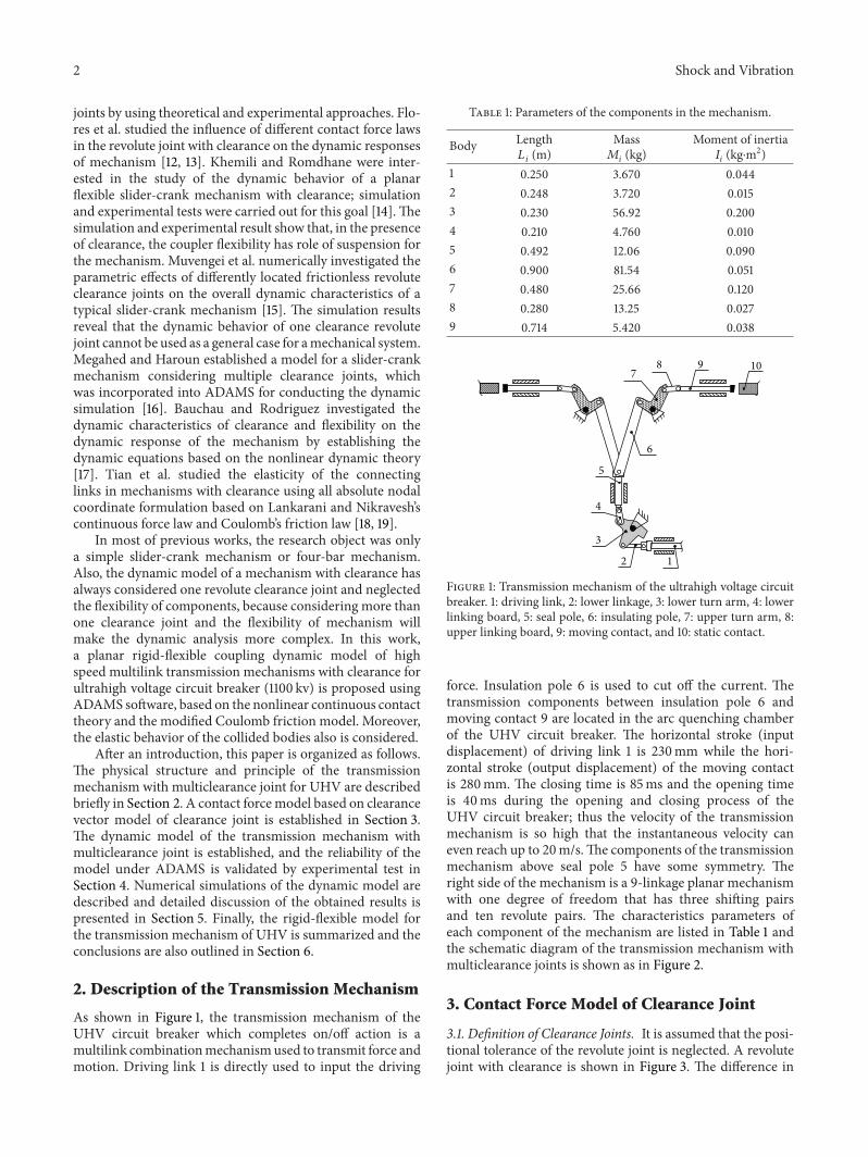
As shown in Figure 1 the transmission mechanism of theUHV circuit breaker which completes onoff action is amultilink combinationmechanismused to transmit force andmotion Driving link 1 is directly used to input the driving
Table 1 Parameters of the components in the mechanism
Body Length119871119894(m)
Mass119872119894(kg)
Moment of inertia119868119894(kgsdotm2)
1 0250 3670 00442 0248 3720 00153 0230 5692 02004 0210 4760 00105 0492 1206 00906 0900 8154 00517 0480 2566 01208 0280 1325 00279 0714 5420 0038
109
2
3
4
5
6
78
1
Figure 1 Transmission mechanism of the ultrahigh voltage circuitbreaker 1 driving link 2 lower linkage 3 lower turn arm 4 lowerlinking board 5 seal pole 6 insulating pole 7 upper turn arm 8upper linking board 9 moving contact and 10 static contact
force Insulation pole 6 is used to cut off the current Thetransmission components between insulation pole 6 andmoving contact 9 are located in the arc quenching chamberof the UHV circuit breaker The horizontal stroke (inputdisplacement) of driving link 1 is 230mm while the hori-zontal stroke (output displacement) of the moving contactis 280mm The closing time is 85ms and the opening timeis 40ms during the opening and closing process of theUHV circuit breaker thus the velocity of the transmissionmechanism is so high that the instantaneous velocity caneven reach up to 20msThe components of the transmissionmechanism above seal pole 5 have some symmetry Theright side of the mechanism is a 9-linkage planar mechanismwith one degree of freedom that has three shifting pairsand ten revolute pairs The characteristics parameters ofeach component of the mechanism are listed in Table 1 andthe schematic diagram of the transmission mechanism withmulticlearance joints is shown as in Figure 2
3 Contact Force Model of Clearance Joint
31 Definition of Clearance Joints It is assumed that the posi-tional tolerance of the revolute joint is neglected A revolutejoint with clearance is shown in Figure 3 The difference in
Shock and Vibration 3
AB
CD
E
FF998400
G
H
I J
G998400
H998400
I998400J998400
Figure 2 Schematic diagram of the transmission mechanism withmulticlearance joints
RB
RJc Bearing
Journal
X
Y
O
Figure 3 Schematic diagram of revolute joint with clearance
radius between the bearing and the journal represents the sizeof the radial clearance
Although a revolute joint with clearance does not con-strain any degree of freedom from the mechanism it intro-duces some kinematic constraints This limits the journalto move within the bearing boundaries Therefore twokinematic constraints are removed and two extra degrees offreedom are introduced instead in a revolute clearance joint
The difference in radius between the bearing and thejournal is as follows
119888 = 119877119861minus 119877119869 (1)
where 119877119861and 119877
119869represent the radius of bearing and journal
Figure 4 depicts the three different types of motionbetween the bearing and journal during dynamics of therealistic revolute joint with clearance (a) free flight mode
in which the journal and bearing are not in contact andthe journal moves freely within the bearing boundaries (b)impact mode which presents at the end of the free flightmode and (c) continuous contact mode that is contactis always maintained despite the relative penetration depthbetween the bearing and journal
Where 119874119894and 119874
119895are the centers of bearing and journal
ri and rj represent the position vectors of bearing and journalin the global inertia coordinateThus clearance vector can begiven by
eij = ri minus rj (2)
where eij represents the eccentric vector of journal relativeto bearing So the eccentricity of bearing and journal can bedescribed as
119890119894119895= radic1198902119909+ 1198902119910 (3)
The unit normal vector at the contact point of the bearingand journal is represented as
n =
eij119890119894119895
(4)
Figure 4(c) describes the relative penetration depthbetween the bearing and journal which are represented inglobal coordinate system The penetration depth caused bycollision between bearing and journal can be stated as follows
120575 = 119890119894119895minus 119888 (5)
32 Normal Force Model of Clearance Joint For the modelingof the contact the contact method based on the INPACTfunction is used to model In this method the contact forcefrom the INPACT function is calculated by theADAMS func-tion libraryThe contact force is essentially modeled as a non-linear spring-damper From the simulations ADAMSSolvercan give a continuous flow of responses including accelera-tions velocities positions and forces from all the elementsand points of contact This continuous contact force model iswidely used for contact-impact process of mechanism systemwith joint clearance [10 14]
It is clear that the normal contact model in ADAMS canbe expressed as
119865119899=
0 120575 le 0
119870120575119899+ 119863 120575 120575 gt 0
(6)
where 119870120575119899 represents the elastic deformation force 119863(120575) 120575
represents the energy dissipation 120575 is the penetration depthand 120575 is the relative impact velocityThe exponent of the forcedeformation characteristic 119899 depends on the material of thecontact surfaces (119899 is set to 15 formetallicmaterial) [20]119863(120575)
4 Shock and Vibration
RB
ex
ey
Y
RJ
O
X
rirj
eij
(a) Free light mode
tFnFt
Oi
Collision plane
Bearing
Journal
X
Y
Oi+1
RB
RJ
O
ri rj
eij
n
(b) Impact mode
120575i
RJ
RB
X
Y
O
ri
rj
eij
(c) Contact mode
Figure 4 Realistic revolute joint with clearance
is the instantaneous damping coefficient which can be givenby
119863 (120575)
=
0 120575 le 0
119863max (120575
119889max)
2
(3 minus 2120575
119889max) 0 lt 120575 le 119889max
119863max 120575 gt 119889max
(7)
where119863max is themaximumvalue of the damping coefficient119889max is the maximum value of penetration depth and 119863(120575)
is a function with respect to 119863max 120575 and 119889max as shown inFigure 5 One has
119867avg =2119870 (1 minus 119903
2)
4120575∙minus
119863max = 119867avg119889119899
max
(8)
0dmax penetration 120575
Dmax
D(120575) function
Damping coefficient D
Figure 5119863(120575) function
The maximum damping coefficient 119863max is calculatedusing (8) and more accurate values of 119863max can be obtainedby updating the values of 119863max and 120575
∙minus using numericaliteration till the value of119863max is stabilized
Shock and Vibration 5
Coe
ffici
ent o
f fric
tion
minussminusd
s d
120583s
120583d
minus120583s
minus120583d
0
Slip velocity
Figure 6 Coefficient of friction versus slip velocity
The stiffness parameter 119870 can be calculated as follows
119870 =4
3 (1205901+ 1205902)[
11987711198772
1198771+ 1198772
]
12
120590119894=
(1 minus V2119894)
119864119894
(119894 = 1 2)
1
119864lowast=
(1 minus V21)
1198641
+
(1 minus V22)
1198642
(9)
where 1198771and 119877
2represent respectively the radii of bearing
and journal V119894is Poissonrsquos ratio and 119864
119894is Yongrsquos modulus for
element 119894
The expression of nonlinear continuous contact forcemodel is expressed as follows
119865119899=
0 120575 le 0
119870120575119899+ 119863 120575 120575 gt 0
(10)
33 Friction Force Model of Clearance Joint In this paper thetangential contact force of clearance is calculated using themodified Coulomb friction model [21] Friction coefficientof the modified Coulomb friction model is function of tan-gential sliding velocity which can avoid the abrupt change offriction in the course of numerical calculating as the change ofvelocity direction And also the modified Coulomb frictioninduces the viscous and microslip phenomenon in relativemotion more accurately
The tangential contact forcesmodel can be represented by
119865119905= minus120583 (V
119905) 119865119899
V119905
1003816100381610038161003816V1199051003816100381610038161003816
(11)
where V119905is sliding velocity in tangential direction at the
collision point of journal and bearing that is the velocitycomponent in tangential direction
120583(V119905) is friction coefficient which can be expressed as
120583 (V119905) =
minus120583119889sign (V
119905) for 1003816100381610038161003816V119905
1003816100381610038161003816 gt V119889
minus120583119889+ (120583119904minus 120583119889) (
1003816100381610038161003816V1199051003816100381610038161003816 minus V119904
V119889minus V119904
)
2
[3 minus 2(
1003816100381610038161003816V1199051003816100381610038161003816 minus V119904
V119889minus V119904
)] sign (V119905) for V
119904lt1003816100381610038161003816V1199051003816100381610038161003816 lt V119889
minus120583119904minus 2120583119904(V119905+ V119904
2V119904
)
2
(3 minusV119905+ V119904
V119904
) for 1003816100381610038161003816V1199051003816100381610038161003816 lt V119904
(12)
where V119889is maximum critical velocity of the kinetic friction
V119904is critical velocity of static friction 120583
119889is kinetic friction
coefficient and 120583119904is static friction coefficient The function
curve of kinetic friction coefficient can be described as inFigure 6
4 Modeling of the Mechanism with Clearanceand Experimental Verification
41 Dynamic Model of Transmission Mechanism of UHV withClearance The high speed multilink transmission mech-anism of UHV with multiclearance joint was establishedunder ADAMS as shown in Figure 7 During the dynamicsimulation of ADAMS it is assumed that the revolute jointswith clearance are studied under the condition of dry lubri-cation and no wear occurs at the joints The insulating poleupper turn arm upper linking board and 119905 moving contact
are flexible which are established under the finite elementsoftware HYPERMESH for obtaining their eigenfrequenciesand eigenmodes (Figure 8) The material properties of theflexible components are presented in Table 2 Moreover thefirst twelvemodeswith corresponding natural frequencies arechosen for the simulation of dynamics of the rigid-flexiblecoupling mechanism with clearance The modal neutral files(mnf) of flexible components are exported into the ADAMSto connect with other rigid components of the mechanismThe rigid-flexible coupling model of transmission mecha-nism with multiclearance joints under ADAMS can obtainmore accurate dynamic responses of the mechanism
In order to obtain the best numerical results the GearStiff (GSTIFF) integrator is chosen which uses a backwardsdifferentiation formula (BDF) to integrate differential andalgebraic standard index-three equations It provides goodsolutions for simulations of stiffmodels (models with amix ofhigh and low frequencies) using modified Newton-Raphson
6 Shock and Vibration
The transmission mechanism of UHV with multiclearance joint modeled under ADAMS
Closing position Opening position
Figure 7 Transmission mechanism modeled in ADAMS
Natural frequency 5645Hz
Undeformed flexible element
Natural frequency 15608Hz Natural frequency 27486Hz
First mode
Natural frequency 9718Hz
Undeformed flexible element
Natural frequency 11948Hz Natural frequency 16074Hz
Natural frequency 9214Hz
Undeformed flexible element
Natural frequency 10557Hz Natural frequency 13095Hz
Second mode Third mode Second mode Third mode
Natural frequency 2661Hz
Undeformed flexible element
Natural frequency 5732Hz Natural frequency 7134Hz
Second mode Third mode Second mode Third mode
Upper turn arm Insulating pole
Moving contact Upper linking board
First mode
First mode First mode
Figure 8 Flexible coupler eigenfrequencies and eigenmodes computation
Shock and Vibration 7
(a) Magnetic railings ruler (b) The installation of sensor
(c) ACTAS tester (d) Test interface
Figure 9 Experimental test system
Table 2 The material properties of the flexible components
Flexible components Modulus ofelasticity (Pa)
Poissonrsquosration
Density(kgm3)
Insulating pole 103 times 1012 03 7600Upper turn arm 211 times 1012 025 7850Upper linking board 211 times 1012 0277 7850Moving contact 213 times 1012 0286 7870
iterative algorithm in the numerical integrating of the differ-ence equation [22] The maximum number of the iterationsallowed for the solution of the nonlinear equations usingNewton-Raphson method to converge is ten The integratorformulation (SI1) has been chosen for the selected integrationmethod (GSTIFF) since it takes the constraint derivativesinto account when solving the equations of motion andmonitors the integration error on the impulse of the LagrangeMultipliers in the system The contact model of Section 3 isincorporated into ADAMS which is used to simulate theclearance joint The simulation characteristics are listed inTable 3
42 Experimental Verification The experimental test sys-tem is shown in Figure 9 The displacement of seal poleis measured by using magnetic railings ruler which canreduce the negative impact of mechanical vibration on theexperimental test The rotational angular velocity of lowerturn arm is measured by using ROS Photoelectric Rotating-Speed Sensor which can avoid the influence of extra load on
Table 3 Simulation characteristics
Stiffness coefficients 119870 (Nm) 381 times 107
Force exponent 119899 15Damping coefficient119863 (Nsdotsm) 381 times 105
Normal maximum penetration 120575max (m) 10 times 10minus5
Static friction coefficient 120583119904
02Dynamic friction coefficient 120583
119889016
Stiction translation velocity V119904(ms) 10 times 10minus4
Friction translation velocity V119889(ms) 10 times 10minus2
Radius of the solids in contact 119877 (m) 005Modulus of elasticity 119864 (Pa) 207 times 1011
Poissonrsquos ratio 120583 03Density 120588 (kgm3) 78 times 103
Max number of iteration 100Initial time step 10 times 10minus7
Max time step 10 times 10minus3
Min time step 10 times 10minus9
Accuracy 10 times 10minus7
Jacobian pattern 100
the experimental testThen Germanrsquos ACTAS tester was usedfor treatment of experimental data which can confirm highaccuracy and reliability on the treatment of experimental datafor its high accuracy and linear frequency responses undervarious complex electromagnetic environments
Figure 11 shows a comparison between the experimentaland the simulation results During the dynamic simulation
8 Shock and Vibration
0 50 100 150 200
minus3
minus2
minus1
0
1times105
Displacement (mm)
Forc
e (N
)
ClosingOpening
(a) Driving force of the driving link
0 50 100 150 2000
1
2
3
4
5
6
7
8times104
Displacement (mm)
Forc
e (N
)
ClosingOpening
(b) Load force of the moving contact
Figure 10 Driving force and load force
the driving force of the driving link and the load force of themoving contact can be expressed as in Figure 10The revolutejoints 119860 and 119861 (Figure 2) of the rigid-flexible couplingmodel were modeled as clearance joints and others are idealrevolute joints The clearance size of the revolute joint is setto be 01mm for the present work which is supported bymanufacturing error and assemblage It is shown that thesimulation and experimental results are in good agreement
5 Result and Discussion
In order to study the dynamic characteristics of transmissionmechanism with multiclearance joints the STEP5 functionin ADAMS is selected as input function of motion TheSTEP5 function provides approximation to the Heavisidestep function with a quintic polynomial which can meetthe requirements for input displacement and closing time oftransmission mechanism
The format defining the STEP5 function is
STEP5 (119909 1199090 ℎ0 1199091 ℎ1) (13)
where 119909 is the independent variable 1199090and 119909
1are real
variables that specify the 119909 value at which the STEP5 functionbegins and ends respectively and ℎ
0and ℎ1are the initial and
final value of the stepThe equation defining the STEP5 function is
120572 = ℎ1minus ℎ0
Δ =(119909 minus 119909
0)
(1199091minus 1199090)
STEP5
=
ℎ0
119909 le 1199090
ℎ0+ 120572Δ3[10 minus 15Δ + 6Δ
2] 1199090lt 119909 le 119909
1
ℎ1
119909 gt 1199091
(14)
During the dynamic simulation the motion time ofthe mechanism is 0085 s and the input stroke is 230mmtherefore the input function STEP5 can be set as
STEP5 (time 0 0 0085 230) (15)
The input displacement of motion and correspondinginput velocity can be described as in Figure 12
51 Dynamic Responses Based on the RigidModel of the Trans-mission Mechanism with Clearance During the dynamicsimulation the revolute joints 119860 and 119869 (Figure 2) of therigid-flexible coupling model are modeled as clearance jointsand others are ideal revolute joints The clearance size ofthe revolute joint is set to 01mm while the simulationtime duration is 0085 s The displacement velocity andacceleration of the moving contact for rigid model are shownin Figure 13
As can be observed fromFigure 13 the effects of clearanceon acceleration of transmission mechanism are severer thanthe effects of clearance on displacement and velocity Thedisplacement and velocity of the transmission mechanismwith clearance are generally consistent with those withoutclearance The deviation value of the output stroke of themoving contact is 01mm The existence of clearance leadsto oscillating and time delay of the velocity Remarkably theexistence of clearance induces the high-frequency shake of
Shock and Vibration 9
0 001 002 003 004 005 006 007 0080
50
100
150
200
250
300
Disp
lace
men
t (m
ms
)
Time (s)
SimulationExperimental
(a) Displacement of moving contact in the closing process
0 0005 001 0015 002 0025 003 0035 0040
50
100
150
200
250
300
Disp
lace
men
t (m
ms
)
Time (s)
SimulationExperimental
(b) Displacement of moving contact in the opening process
0005 001 0015 002 0025 003 00350
2000
4000
6000
8000
10000
12000
14000
16000
Velo
city
(mm
s)
Time (s)
SimulationExperimental
(c) Velocity of moving contact in the opening process
001 002 003 004 005 006 007 008500
1000
1500
2000
2500
3000
3500
4000
4500
5000
Velo
city
(mm
s)
Time (s)
SimulationExperimental
(d) Velocity of moving contact in the opening process
Figure 11 Simulation and experimental results
acceleration and the maximum value of acceleration of themechanism is 229 times more than that of the mechanismwithout clearance It is clear that the existence of the clearancejoint has an important effect on the dynamic response of themechanism and the clearance joint must be considered forreliable analysis of the mechanisms
52 Dynamic Responses Based on the Rigid-Flexible CouplingModel of Transmission Mechanism with Clearance In orderto highlight the effect of flexibility the same simulation char-acteristics as in the case of the rigid transmission mechanismare chosenThedisplacement velocity and acceleration of themoving contact for rigid-flexible coupling model are shownin Figure 14
As can be seen from Figure 14 the displacement andvelocity of the transmission mechanism with clearance are
Disp
lace
men
t (m
m)
Velo
city
(mm
s)
Time (s)0 001 002 003 004 005 006 007 008
0
2000
4000
6000
0
100
200
300
VelocityDisplacement
Figure 12 Characteristics of the input displacement and velocity(STEP5)
10 Shock and VibrationD
ispla
cem
ent (
mm
)
Time (s)001 002 003 004 005 006 007 008
0
50
100
150
200
250
300
Without clearanceWith clearance
(a)
00849 008527995
280
28005
2801
28015
2802
Disp
lace
men
t (m
m)
Time (s)
Without clearanceWith clearance
(b)
0 001 002 003 004 005 006 007 0080
1000
2000
3000
4000
5000
6000
7000
Velo
city
(mm
s)
Time (s)
Without clearanceWith clearance
(c)
0 1 2 3 4 5
times10minus3
0
50
100
150
200
250
300
350
400Ve
loci
ty (m
ms
)
Time (s)
Without clearanceWith clearance
(d)
0 001 002 003 004 005 006 007 0080
1
2
3
4
5
6times105
Acce
lera
tion
(mm
s2)
Time (s)
Without clearanceWith clearance
(e)
Figure 13 Responses based on the rigid model with clearance (a) displacement (b) enlarged drawing of displacement (c) velocity(d) enlarged drawing of velocity and (e) acceleration
Shock and Vibration 11D
ispla
cem
ent (
mm
)
Time (s)001 002 003 004 005 006 007 008
0
50
100
150
200
250
300
Without clearanceWith clearance
(a)
00849 00852799
27995
280
28005
2801
Disp
lace
men
t (m
m)
Time (s)
Without clearanceWith clearance
(b)
0 001 002 003 004 005 006 007 0080
1000
2000
3000
4000
5000
6000
Velo
city
(mm
s)
Time (s)
Without clearanceWith clearance
(c)
0 2 4 6 8 10
times10minus3
0
100
200
300
400
500
600
700
800Ve
loci
ty (m
ms
)
Time (s)
Without clearanceWith clearance
(d)
001 002 003 004 005 006 007 0080
1
2
3
4
5
6
7times105
Acce
lera
tion
(mm
s2)
Time (s)
Without clearanceWith clearance
(e)
Figure 14 Responses based on the rigid-flexible coupling model with clearance (a) displacement (b) enlarged drawing of displacement(c) velocity (d) enlarged drawing of velocity and (e) acceleration
12 Shock and Vibration
0 001 002 003 004 005 006 007 0080
50
100
150
200
250
300
c = 005mmc = 01mm
c = 02mm
Time (s)
(a)
00849 0085280
28005
2801
28015
2802
28025
2803
c = 005mmc = 01mm
c = 02mm
Time (s)
(b)
Velo
city
(mm
s)
0 001 002 003 004 005 006 007 0080
1000
2000
3000
4000
5000
6000
7000
c = 005mmc = 01mm
c = 02mm
Time (s)
(c)
0 1 2 3 4 5
times10minus3
0
50
100
150
200
250
300
350
400
c = 005mmc = 01mm
c = 02mm
Time (s)
Velo
city
(mm
s)
(d)
0 001 002 003 004 005 006 007 0080
1
2
3
4
5
6
7times105
Acce
lera
tion
(mm
s2)
c = 005mmc = 01mm
c = 02mm
Time (s)
(e)
0 001 002 003 004 005 006 007 0080
1000
2000
3000
4000
Con
tact
forc
e (N
)
c = 005mmc = 01mm
c = 02mm
Time (s)
(f)
Figure 15 Responses for different clearance sizes (a) displacement (b) enlarged drawing of displacement (c) velocity (d) enlarged drawingof velocity (e) acceleration and (f) contact force
Shock and Vibration 13
0 001 002 003 004 005 006 007 0080
5
10
15
0
5
10
Upper linking boardUpper turn armMoving contact
Insulating pole
Von
Mise
s stre
ss (M
Pa)
Time (s)
(a)
0 001 002 003 004 005 006 007 0080
5
10
15
20
0
5
10
15
c = 005mmc = 01mm
c = 02mm
Time (s)
Von
Mise
s stre
ss (M
Pa)
(b)
Figure 16 Dynamic stress for different clearance sizes (a) Von Mises stress of the components and (b) Von Mises stress of upper turn arm
generally consistent with those without clearance The devia-tion value of the output stroke is 008mmComparedwith therigid model without clearance velocity and acceleration ofthe rigid-flexible coupling model without clearance producelarge amplitude vibration in the starting stage of motionthe reason is that the high speed moving of transmissionmechanism causes the excessive deformation of the flexiblecomponents especially for the moving contact restrictedby shifting pairs which leads to clamping stagnation inthe transmission motion As can be seen from Figure 14(e)the existence of clearance can highly reduce the impactand vibration of the transmission mechanism That is theexistence of clearance acts as the suspension for the rigid-flexible coupling model
Compared with the acceleration of rigid model withclearance themaximumvalue of acceleration of rigid-flexiblecoupling model with clearance is reduced from 5635ms2to 4602ms2 Therefore for the case of the rigid-flexiblecoupling model the maximum value of acceleration andimpacts are dramatically reduced and the elastic componentsact as a suspension for the mechanism
53 Influence of the Clearance Size The effect of the clearancesize on the dynamic responses of the rigid-flexible couplingmodel of the mechanism is investigated During the dynamicsimulation the revolute joints119860 and 119869 (Figure 2) aremodeledas clearance joints Three case studies are implementedfor the different clearance sizes of 005mm 01mm and02mm The displacement vibration displacement velocityand acceleration of themoving contact for different clearancesizes are shown in Figure 15
It is clear that the effects of the clearance sizes for revolutejoint on the displacement and velocity of moving contactare slight since the displacement and the velocity of movingcontact without clearance are generally consistent with thoseof moving contact with different clearance sizes However
with the increase in clearance size the deviation value of theoutput stroke the fluctuation frequency and the hystereticnature of velocity in time domain are more obvious Whenthe clearance size increases from 005mm to 02mm thecorresponding deviation value of the output stroke increasesfrom 004mm to 017mm Particularly the time delay ofvelocity in the starting stage ofmotion increases from00015 sto 00044 s Although the time is very short it will lead toa kinematic error of about 78 percent for the transmissionmechanismwith characteristics of high speed and heavy haulwhich causes a huge negative effect for transmission motioneven a serious Power Grid Accident
The simulation results also verify that the effects ofclearance size on contact force at the joint and acceleration oftransmission mechanism are severer than those on displace-ment and velocity especially for the high speed mechanismRemarkably the maximum value of acceleration increasesfrom 3455ms2 to 6122ms2 the maximum value of contactforce in joint (119869) increases from 20324N to 36806N Theexcessive contact force of the joints will greatly reduce thelifespan and dynamic performance of the mechanism
As can be seen from Figure 16 during the simulation themaximum dynamic stress of transmissionmechanism occursat the chamfer of upper turn arm The reason is that it isconstrained to the fixed axis rotation and has thin-walledstructure in chamfer zone which leads to bending momentsand stress concentration It can be seen that with theincrease in the clearance size the maximum dynamic stressof upper turn arm increases from 1363MPa to 1871MPaThesimulation results indicate that the increase of the clearancesize increases the level of dynamic stress of mechanismobviously
In addition the simulation results are compared toother studies form previous literature [23ndash25] in whichthe research results also revealed that clearance size playedimportant roles in the dynamic performance of mechanical
14 Shock and Vibration
Disp
lace
men
t (m
m)
Input displacement (mm)0 50 100 150 200
0
50
100
150
200
250
300
004 s006 s
0085 s
(a)
Velo
city
(mm
s)
0 50 100 150 2000
2000
4000
6000
8000
10000
12000
14000
Input displacement (mm)
004 s006 s
0085 s
(b)
0 50 100 150 2000
2
4
6
8
10
12
14
16
18
times105
Acce
lera
tion
(mm
s2)
Input displacement (mm)
004 s006 s
0085 s
(c)
0 50 100 150 2000
2000
4000
6000
8000
10000
12000C
onta
ct fo
rce (
N)
Input displacement (mm)
004 s006 s
0085 s
(d)
Figure 17 Responses for different input speeds (a) displacement (b) velocity (c) acceleration and (d) contact force
system It also represented that clearance leads to oscillationsof mechanism and higher size of clearance leads to largeramplitude of the acceleration of mechanism So the simula-tion results are validated by other data published on the fieldon dynamics of mechanism with clearance joints
54 Influence of the Input Speed The influence of the inputspeed of driving link on the dynamic responses of the rigid-flexible coupling transmission mechanism is investigated inthis section Again in the simulation of transmission mech-anism the revolute joints 119860 and 119869 (Figure 2) are modeled asclearance jointsThe clearance size of the revolute joints is setto 01mm
When driving linkrsquos stroke is 230mm the time durationof the simulation of transmission mechanism was 004 s
006 s and 0085 s respectively That is the input func-tion of motion is respectively step5(time 0 0 004 230)step5(time 0 0 006 230) and step5(time 0 0 0085 230)The displacement velocity acceleration and contact forceof the rigid-flexible coupling transmission mechanism withclearance are shown in Figure 17
As can be seen from Figure 17 the different input speedsof driving link do not affect the displacement of movingcontact in a significant way In sharp contrast the velocityacceleration and contact force ofmoving contact are stronglyaffected by input speed of driving link With the increase ininput speed of driving link the maximum value of velocity ofmoving contact increases from 621ms to 1331ms the valueof contact force in clearance joint (119869) increases from 3820N to9754N and that of acceleration increases from 4602mms2
Shock and Vibration 15
0 001 002 003 004 005 006 007 0080
50
100
150
200
250
300
Disp
lace
men
t (m
m)
11 clearance joints15 clearance joints3 clearance joints
1 clearance joint
Time (s)
(a)
Disp
lace
men
t (m
m)
00849 0085280
2801
2802
2803
2804
2805
2806
2807
2808
Time (s)
11 clearance joints15 clearance joints3 clearance joints
1 clearance joint
(b)
Velo
city
(mm
s)
0 001 002 003 004 005 006 007 008 0090
1000
2000
3000
4000
5000
6000
7000
Time (s)
11 clearance joints15 clearance joints3 clearance joints
1 clearance joint
(c)
Velo
city
(mm
s)
1 2 3 4 5 6
times10minus3
0
50
100
150
200
250
300
350
400
Time (s)
11 clearance joints15 clearance joints3 clearance joints
1 clearance joint
(d)
001 002 003 004 005 006 007 0080
1
2
3
4
times106
Acce
lera
tion
(mm
s2)
Time (s)
11 clearance joints15 clearance joints3 clearance joints
1 clearance joint
(e)
Figure 18 Responses for different number of clearance joints (a) displacement (b) enlarged drawing of displacement (c) velocity(d) enlarged drawing of velocity and (e) acceleration
16 Shock and Vibration
to 16256ms2 It indicates the higher input speed the higheracceleration and contact force Therefore as the input speedincreases the effects of clearance on dynamic response of themechanism are more obvious
55 Influence of the Number of Clearance Joints The sim-ulation of transmission mechanism is performed with onefour eleven and fifteen clearance joints In the simulationthe clearance size of revolute joint is set to be 01mm andthe simulation time duration is 0085 s the displacementvelocity and acceleration of the moving contact for differentnumber of clearance joints are shown in Figure 18
As can be seen from Figure 18 an increase in numberof clearance joints causes the enhancement of the dynamicresponse of transmission mechanism When the number ofclearance joints increases from 1 to 15 the correspondingdeviation value of the output stroke increases from 008mmto 054mm the time delay of velocity in the starting stageof motion increases from 00015 s to 00044 s and themaximum value of acceleration increases from 3315ms2 to42606ms2 With the increase of the number of clearancejoints the impact strength and vibration frequency will bestronger and higher Therefore the dynamic responses oftransmission mechanism are affected tremendously by thenumber of clearance joints As the number of clearance jointsincreases the dynamic responses of the mechanism are moresevere
6 ConclusionIn this work a planar rigid-flexible coupling model ofthe transmission mechanism of (UHV) with multiclearancejoints is established using ADAMS software The dynamiccontact model in clearance joints is performed in whichthe normal force is considered using nonlinear continuouscontact force model and tangential force is considered usingmodified Coulombrsquos friction model The reliability of themodel is proved by means of comparing the results of experi-ments Moreover drawing into calculator simulationmethodfor supplement because of the limitations on experiment ithas greater applicable scope
The simulation results show that the dynamic responseof the mechanism is influenced greatly by the clearance andcomponents flexibility Comparedwith the rigidmodel in thecase of flexible model the maximum value of acceleration ishighly reduced to about 15 times and flexible componentsact as a suspension for the mechanism Furthermore theinfluences of clearance size input speed and number ofclearance joints on the dynamic response of the mechanismare also investigated It can be included that the increasedclearance size number of clearance joints and input speedmake the dynamic responses of mechanism worse whichleads to the destruction and failure of components andperforms as more obvious motion lag and impact In addi-tion this work provides a practical method to analyze thedynamics characteristics of transmission mechanism withclearance joints and can predict the effects of clearanceon transmission mechanism preferably which is the basisfor precision analysis optimization design of transmissionmechanism and reliability operation of breaker circuit
Conflict of Interests
The authors declare that there is no conflict of interestsregarding the publication of this paper
Acknowledgment
The authors would like to express sincere gratitude to thePinggao Technology for the financial and technologicalsupport given to this study through the project ldquoHigh VoltageCircuit Breaker Hydraulic Operating Mechanism Character-istic Researchrdquo (Project no 208239881)
References
[1] G Song J Cui andD Yuan ldquoOperating analysis of high voltagecircuit breaker in 1999ndash2003rdquo Electrical Equipment vol 6 no 2pp 6ndash13 2005
[2] A Ziani and H Moulai ldquoHybrid model of electric arcs in highvoltage circuit breakersrdquo Electric Power Systems Research vol92 pp 37ndash42 2012
[3] W Liu and B Xu ldquoCharacteristic analysis of high voltagecircuit breaker with hydraulic operating mechanismrdquo Journalof Mechanical Engineering vol 46 no 10 pp 148ndash155 2010
[4] F-C Chen and Y-F Tzeng ldquoOn the dynamics of spring-typeoperating mechanism for 69 KV SF6 gas insulated circuitbreaker in open operationrdquo Computers and Structures vol 80no 22 pp 1715ndash1723 2002
[5] F-C Chen ldquoDynamic response of spring-type operatingmech-anism for 69 kV SF6 gas insulated circuit breakerrdquo Mechanismand Machine Theory vol 38 no 2 pp 119ndash134 2003
[6] T-M Lyu and J-P Tao ldquoCalculation and improvement of springoperating mine-used device for vacuum circuit breakerrdquo CoalMine Machinery vol 35 no 9 pp 34ndash36 2012
[7] P Flores ldquoAparametric study on the dynamic response of planarmultibody systems with multiple clearance jointsrdquo NonlinearDynamics vol 61 no 4 pp 633ndash653 2010
[8] S Erkaya and I Uzmay ldquoA neural-genetic (NN-GA) approachfor optimisingmechanisms having joints with clearancerdquoMulti-body System Dynamics vol 20 no 1 pp 69ndash83 2008
[9] Q Tian Y Zhang L Chen and P Flores ldquoDynamics ofspatial flexiblemultibody systems with clearance and lubricatedspherical jointsrdquoComputers and Structures vol 87 no 13-14 pp913ndash929 2009
[10] E Zheng and X Zhou ldquoModeling and simulation of flexibleslider-crank mechanism with clearance for a closed high speedpress systemrdquo Mechanism and Machine Theory vol 74 pp 10ndash30 2014
[11] Z-F Bai Y Zhao and H Tian ldquoDynamics simulation ofdeployment for solar panels with hinge clearancerdquo Journal ofHarbin Institute of Technology vol 41 no 3 pp 11ndash14 2009
[12] P Flores J Ambrosio and J P Claro ldquoDynamic analysis forplanar multibody mechanical systems with lubricated jointsrdquoMultibody System Dynamics vol 12 no 1 pp 47ndash74 2004
[13] P Flores J Ambrosio J C P Claro and H M LankaranildquoInfluence of the contact-impact force model on the dynamicresponse of multi-body systemsrdquo Proceedings of the Institutionof Mechanical Engineers Part K vol 220 no 1 pp 21ndash34 2006
[14] I Khemili and L Romdhane ldquoDynamic analysis of a flexibleslider-crank mechanism with clearancerdquo European Journal ofMechanicsmdashASolids vol 27 no 5 pp 882ndash898 2008
Shock and Vibration 17
[15] O Muvengei J Kihiu and B Ikua ldquoNumerical study of para-metric effects on the dynamic response of planar multi-bodysystems with differently located frictionless revolute clearancejointsrdquoMechanism andMachineTheory vol 53 pp 30ndash49 2012
[16] S M Megahed and A F Haroun ldquoAnalysis of the dynamicbehavioral performance of mechanical systems with multi-clearance jointsrdquo Journal of Computational and NonlinearDynamics vol 7 no 1 Article ID 011002 11 pages 2012
[17] O A Bauchau and J Rodriguez ldquoModeling of joint clearancesand joint flexibility effects in multibody systems dynamicsrdquoInternational Journal of Solids and Structures no 39 pp 41ndash632002
[18] Q Tian Y Zhang L Chen and J Yang ldquoSimulation ofplanar flexible multibody systems with clearance and lubricatedrevolute jointsrdquoNonlinear Dynamics vol 60 no 4 pp 489ndash5112010
[19] Q Tian C Liu M MacHado and P Flores ldquoA new model fordry and lubricated cylindrical joints with clearance in spatialflexible multibody systemsrdquo Nonlinear Dynamics vol 64 no 1-2 pp 25ndash47 2011
[20] A L Schwab J P Meijaard and P Meijers ldquoA comparisonof revolute joint clearance models in the dynamic analysis ofrigid and elastic mechanical systemsrdquoMechanism and MachineTheory vol 37 no 9 pp 895ndash913 2002
[21] Z F Bai and Y Zhao ldquoA hybrid contact force model ofrevolute joint with clearance for planar mechanical systemsrdquoInternational Journal of Non-Linear Mechanics vol 48 pp 15ndash36 2013
[22] D-Y Yu and Y-J Qian ldquoParameter-settings for the dynamicsimulation based on ADAMSrdquo Computer Simulation no 9 pp103ndash107 2006
[23] S Erkaya ldquoInvestigation of joint clearance effects on weldingrobot manipulatorsrdquo Robotics and Computer-Integrated Manu-facturing vol 28 no 4 pp 449ndash457 2012
[24] K-L Ting J Zhu and D Watkins ldquoThe effects of jointclearance on position and orientation deviation of linkages andmanipulatorsrdquo Mechanism and Machine Theory vol 35 no 3pp 391ndash401 2000
[25] A Kote K Balaji B S Nataraju and V C Aralimatti ldquoEffectof solar array deployment on spacecraft attituderdquo Journal ofSpacecraft Technology vol 17 no 2 pp 1ndash8 2007
International Journal of
AerospaceEngineeringHindawi Publishing Corporationhttpwwwhindawicom Volume 2014
RoboticsJournal of
Hindawi Publishing Corporationhttpwwwhindawicom Volume 2014
Hindawi Publishing Corporationhttpwwwhindawicom Volume 2014
Active and Passive Electronic Components
Control Scienceand Engineering
Journal of
Hindawi Publishing Corporationhttpwwwhindawicom Volume 2014
International Journal of
RotatingMachinery
Hindawi Publishing Corporationhttpwwwhindawicom Volume 2014
Hindawi Publishing Corporation httpwwwhindawicom
Journal ofEngineeringVolume 2014
Submit your manuscripts athttpwwwhindawicom
VLSI Design
Hindawi Publishing Corporationhttpwwwhindawicom Volume 2014
Hindawi Publishing Corporationhttpwwwhindawicom Volume 2014
Shock and Vibration
Hindawi Publishing Corporationhttpwwwhindawicom Volume 2014
Civil EngineeringAdvances in
Acoustics and VibrationAdvances in
Hindawi Publishing Corporationhttpwwwhindawicom Volume 2014
Hindawi Publishing Corporationhttpwwwhindawicom Volume 2014
Electrical and Computer Engineering
Journal of
Advances inOptoElectronics
Hindawi Publishing Corporation httpwwwhindawicom
Volume 2014
The Scientific World JournalHindawi Publishing Corporation httpwwwhindawicom Volume 2014
SensorsJournal of
Hindawi Publishing Corporationhttpwwwhindawicom Volume 2014
Modelling amp Simulation in EngineeringHindawi Publishing Corporation httpwwwhindawicom Volume 2014
Hindawi Publishing Corporationhttpwwwhindawicom Volume 2014
Chemical EngineeringInternational Journal of Antennas and
Propagation
International Journal of
Hindawi Publishing Corporationhttpwwwhindawicom Volume 2014
Hindawi Publishing Corporationhttpwwwhindawicom Volume 2014
Navigation and Observation
International Journal of
Hindawi Publishing Corporationhttpwwwhindawicom Volume 2014
DistributedSensor Networks
International Journal of
2 Shock and Vibration
joints by using theoretical and experimental approaches Flo-res et al studied the influence of different contact force lawsin the revolute joint with clearance on the dynamic responsesof mechanism [12 13] Khemili and Romdhane were inter-ested in the study of the dynamic behavior of a planarflexible slider-crank mechanism with clearance simulationand experimental tests were carried out for this goal [14]Thesimulation and experimental result show that in the presenceof clearance the coupler flexibility has role of suspension forthe mechanism Muvengei et al numerically investigated theparametric effects of differently located frictionless revoluteclearance joints on the overall dynamic characteristics of atypical slider-crank mechanism [15] The simulation resultsreveal that the dynamic behavior of one clearance revolutejoint cannot be used as a general case for amechanical systemMegahed and Haroun established a model for a slider-crankmechanism considering multiple clearance joints whichwas incorporated into ADAMS for conducting the dynamicsimulation [16] Bauchau and Rodriguez investigated thedynamic characteristics of clearance and flexibility on thedynamic response of the mechanism by establishing thedynamic equations based on the nonlinear dynamic theory[17] Tian et al studied the elasticity of the connectinglinks in mechanisms with clearance using all absolute nodalcoordinate formulation based on Lankarani and Nikraveshrsquoscontinuous force law and Coulombrsquos friction law [18 19]
In most of previous works the research object was onlya simple slider-crank mechanism or four-bar mechanismAlso the dynamic model of a mechanism with clearance hasalways considered one revolute clearance joint and neglectedthe flexibility of components because considering more thanone clearance joint and the flexibility of mechanism willmake the dynamic analysis more complex In this worka planar rigid-flexible coupling dynamic model of highspeed multilink transmission mechanisms with clearance forultrahigh voltage circuit breaker (1100 kv) is proposed usingADAMS software based on the nonlinear continuous contacttheory and the modified Coulomb friction model Moreoverthe elastic behavior of the collided bodies also is considered
After an introduction this paper is organized as followsThe physical structure and principle of the transmissionmechanism with multiclearance joint for UHV are describedbriefly in Section 2 A contact forcemodel based on clearancevector model of clearance joint is established in Section 3The dynamic model of the transmission mechanism withmulticlearance joint is established and the reliability of themodel under ADAMS is validated by experimental test inSection 4 Numerical simulations of the dynamic model aredescribed and detailed discussion of the obtained results ispresented in Section 5 Finally the rigid-flexible model forthe transmission mechanism of UHV is summarized and theconclusions are also outlined in Section 6
2 Description of the Transmission Mechanism
As shown in Figure 1 the transmission mechanism of theUHV circuit breaker which completes onoff action is amultilink combinationmechanismused to transmit force andmotion Driving link 1 is directly used to input the driving
Table 1 Parameters of the components in the mechanism
Body Length119871119894(m)
Mass119872119894(kg)
Moment of inertia119868119894(kgsdotm2)
1 0250 3670 00442 0248 3720 00153 0230 5692 02004 0210 4760 00105 0492 1206 00906 0900 8154 00517 0480 2566 01208 0280 1325 00279 0714 5420 0038
109
2
3
4
5
6
78
1
Figure 1 Transmission mechanism of the ultrahigh voltage circuitbreaker 1 driving link 2 lower linkage 3 lower turn arm 4 lowerlinking board 5 seal pole 6 insulating pole 7 upper turn arm 8upper linking board 9 moving contact and 10 static contact
force Insulation pole 6 is used to cut off the current Thetransmission components between insulation pole 6 andmoving contact 9 are located in the arc quenching chamberof the UHV circuit breaker The horizontal stroke (inputdisplacement) of driving link 1 is 230mm while the hori-zontal stroke (output displacement) of the moving contactis 280mm The closing time is 85ms and the opening timeis 40ms during the opening and closing process of theUHV circuit breaker thus the velocity of the transmissionmechanism is so high that the instantaneous velocity caneven reach up to 20msThe components of the transmissionmechanism above seal pole 5 have some symmetry Theright side of the mechanism is a 9-linkage planar mechanismwith one degree of freedom that has three shifting pairsand ten revolute pairs The characteristics parameters ofeach component of the mechanism are listed in Table 1 andthe schematic diagram of the transmission mechanism withmulticlearance joints is shown as in Figure 2
3 Contact Force Model of Clearance Joint
31 Definition of Clearance Joints It is assumed that the posi-tional tolerance of the revolute joint is neglected A revolutejoint with clearance is shown in Figure 3 The difference in
Shock and Vibration 3
AB
CD
E
FF998400
G
H
I J
G998400
H998400
I998400J998400
Figure 2 Schematic diagram of the transmission mechanism withmulticlearance joints
RB
RJc Bearing
Journal
X
Y
O
Figure 3 Schematic diagram of revolute joint with clearance
radius between the bearing and the journal represents the sizeof the radial clearance
Although a revolute joint with clearance does not con-strain any degree of freedom from the mechanism it intro-duces some kinematic constraints This limits the journalto move within the bearing boundaries Therefore twokinematic constraints are removed and two extra degrees offreedom are introduced instead in a revolute clearance joint
The difference in radius between the bearing and thejournal is as follows
119888 = 119877119861minus 119877119869 (1)
where 119877119861and 119877
119869represent the radius of bearing and journal
Figure 4 depicts the three different types of motionbetween the bearing and journal during dynamics of therealistic revolute joint with clearance (a) free flight mode
in which the journal and bearing are not in contact andthe journal moves freely within the bearing boundaries (b)impact mode which presents at the end of the free flightmode and (c) continuous contact mode that is contactis always maintained despite the relative penetration depthbetween the bearing and journal
Where 119874119894and 119874
119895are the centers of bearing and journal
ri and rj represent the position vectors of bearing and journalin the global inertia coordinateThus clearance vector can begiven by
eij = ri minus rj (2)
where eij represents the eccentric vector of journal relativeto bearing So the eccentricity of bearing and journal can bedescribed as
119890119894119895= radic1198902119909+ 1198902119910 (3)
The unit normal vector at the contact point of the bearingand journal is represented as
n =
eij119890119894119895
(4)
Figure 4(c) describes the relative penetration depthbetween the bearing and journal which are represented inglobal coordinate system The penetration depth caused bycollision between bearing and journal can be stated as follows
120575 = 119890119894119895minus 119888 (5)
32 Normal Force Model of Clearance Joint For the modelingof the contact the contact method based on the INPACTfunction is used to model In this method the contact forcefrom the INPACT function is calculated by theADAMS func-tion libraryThe contact force is essentially modeled as a non-linear spring-damper From the simulations ADAMSSolvercan give a continuous flow of responses including accelera-tions velocities positions and forces from all the elementsand points of contact This continuous contact force model iswidely used for contact-impact process of mechanism systemwith joint clearance [10 14]
It is clear that the normal contact model in ADAMS canbe expressed as
119865119899=
0 120575 le 0
119870120575119899+ 119863 120575 120575 gt 0
(6)
where 119870120575119899 represents the elastic deformation force 119863(120575) 120575
represents the energy dissipation 120575 is the penetration depthand 120575 is the relative impact velocityThe exponent of the forcedeformation characteristic 119899 depends on the material of thecontact surfaces (119899 is set to 15 formetallicmaterial) [20]119863(120575)
4 Shock and Vibration
RB
ex
ey
Y
RJ
O
X
rirj
eij
(a) Free light mode
tFnFt
Oi
Collision plane
Bearing
Journal
X
Y
Oi+1
RB
RJ
O
ri rj
eij
n
(b) Impact mode
120575i
RJ
RB
X
Y
O
ri
rj
eij
(c) Contact mode
Figure 4 Realistic revolute joint with clearance
is the instantaneous damping coefficient which can be givenby
119863 (120575)
=
0 120575 le 0
119863max (120575
119889max)
2
(3 minus 2120575
119889max) 0 lt 120575 le 119889max
119863max 120575 gt 119889max
(7)
where119863max is themaximumvalue of the damping coefficient119889max is the maximum value of penetration depth and 119863(120575)
is a function with respect to 119863max 120575 and 119889max as shown inFigure 5 One has
119867avg =2119870 (1 minus 119903
2)
4120575∙minus
119863max = 119867avg119889119899
max
(8)
0dmax penetration 120575
Dmax
D(120575) function
Damping coefficient D
Figure 5119863(120575) function
The maximum damping coefficient 119863max is calculatedusing (8) and more accurate values of 119863max can be obtainedby updating the values of 119863max and 120575
∙minus using numericaliteration till the value of119863max is stabilized
Shock and Vibration 5
Coe
ffici
ent o
f fric
tion
minussminusd
s d
120583s
120583d
minus120583s
minus120583d
0
Slip velocity
Figure 6 Coefficient of friction versus slip velocity
The stiffness parameter 119870 can be calculated as follows
119870 =4
3 (1205901+ 1205902)[
11987711198772
1198771+ 1198772
]
12
120590119894=
(1 minus V2119894)
119864119894
(119894 = 1 2)
1
119864lowast=
(1 minus V21)
1198641
+
(1 minus V22)
1198642
(9)
where 1198771and 119877
2represent respectively the radii of bearing
and journal V119894is Poissonrsquos ratio and 119864
119894is Yongrsquos modulus for
element 119894
The expression of nonlinear continuous contact forcemodel is expressed as follows
119865119899=
0 120575 le 0
119870120575119899+ 119863 120575 120575 gt 0
(10)
33 Friction Force Model of Clearance Joint In this paper thetangential contact force of clearance is calculated using themodified Coulomb friction model [21] Friction coefficientof the modified Coulomb friction model is function of tan-gential sliding velocity which can avoid the abrupt change offriction in the course of numerical calculating as the change ofvelocity direction And also the modified Coulomb frictioninduces the viscous and microslip phenomenon in relativemotion more accurately
The tangential contact forcesmodel can be represented by
119865119905= minus120583 (V
119905) 119865119899
V119905
1003816100381610038161003816V1199051003816100381610038161003816
(11)
where V119905is sliding velocity in tangential direction at the
collision point of journal and bearing that is the velocitycomponent in tangential direction
120583(V119905) is friction coefficient which can be expressed as
120583 (V119905) =
minus120583119889sign (V
119905) for 1003816100381610038161003816V119905
1003816100381610038161003816 gt V119889
minus120583119889+ (120583119904minus 120583119889) (
1003816100381610038161003816V1199051003816100381610038161003816 minus V119904
V119889minus V119904
)
2
[3 minus 2(
1003816100381610038161003816V1199051003816100381610038161003816 minus V119904
V119889minus V119904
)] sign (V119905) for V
119904lt1003816100381610038161003816V1199051003816100381610038161003816 lt V119889
minus120583119904minus 2120583119904(V119905+ V119904
2V119904
)
2
(3 minusV119905+ V119904
V119904
) for 1003816100381610038161003816V1199051003816100381610038161003816 lt V119904
(12)
where V119889is maximum critical velocity of the kinetic friction
V119904is critical velocity of static friction 120583
119889is kinetic friction
coefficient and 120583119904is static friction coefficient The function
curve of kinetic friction coefficient can be described as inFigure 6
4 Modeling of the Mechanism with Clearanceand Experimental Verification
41 Dynamic Model of Transmission Mechanism of UHV withClearance The high speed multilink transmission mech-anism of UHV with multiclearance joint was establishedunder ADAMS as shown in Figure 7 During the dynamicsimulation of ADAMS it is assumed that the revolute jointswith clearance are studied under the condition of dry lubri-cation and no wear occurs at the joints The insulating poleupper turn arm upper linking board and 119905 moving contact
are flexible which are established under the finite elementsoftware HYPERMESH for obtaining their eigenfrequenciesand eigenmodes (Figure 8) The material properties of theflexible components are presented in Table 2 Moreover thefirst twelvemodeswith corresponding natural frequencies arechosen for the simulation of dynamics of the rigid-flexiblecoupling mechanism with clearance The modal neutral files(mnf) of flexible components are exported into the ADAMSto connect with other rigid components of the mechanismThe rigid-flexible coupling model of transmission mecha-nism with multiclearance joints under ADAMS can obtainmore accurate dynamic responses of the mechanism
In order to obtain the best numerical results the GearStiff (GSTIFF) integrator is chosen which uses a backwardsdifferentiation formula (BDF) to integrate differential andalgebraic standard index-three equations It provides goodsolutions for simulations of stiffmodels (models with amix ofhigh and low frequencies) using modified Newton-Raphson
6 Shock and Vibration
The transmission mechanism of UHV with multiclearance joint modeled under ADAMS
Closing position Opening position
Figure 7 Transmission mechanism modeled in ADAMS
Natural frequency 5645Hz
Undeformed flexible element
Natural frequency 15608Hz Natural frequency 27486Hz
First mode
Natural frequency 9718Hz
Undeformed flexible element
Natural frequency 11948Hz Natural frequency 16074Hz
Natural frequency 9214Hz
Undeformed flexible element
Natural frequency 10557Hz Natural frequency 13095Hz
Second mode Third mode Second mode Third mode
Natural frequency 2661Hz
Undeformed flexible element
Natural frequency 5732Hz Natural frequency 7134Hz
Second mode Third mode Second mode Third mode
Upper turn arm Insulating pole
Moving contact Upper linking board
First mode
First mode First mode
Figure 8 Flexible coupler eigenfrequencies and eigenmodes computation
Shock and Vibration 7
(a) Magnetic railings ruler (b) The installation of sensor
(c) ACTAS tester (d) Test interface
Figure 9 Experimental test system
Table 2 The material properties of the flexible components
Flexible components Modulus ofelasticity (Pa)
Poissonrsquosration
Density(kgm3)
Insulating pole 103 times 1012 03 7600Upper turn arm 211 times 1012 025 7850Upper linking board 211 times 1012 0277 7850Moving contact 213 times 1012 0286 7870
iterative algorithm in the numerical integrating of the differ-ence equation [22] The maximum number of the iterationsallowed for the solution of the nonlinear equations usingNewton-Raphson method to converge is ten The integratorformulation (SI1) has been chosen for the selected integrationmethod (GSTIFF) since it takes the constraint derivativesinto account when solving the equations of motion andmonitors the integration error on the impulse of the LagrangeMultipliers in the system The contact model of Section 3 isincorporated into ADAMS which is used to simulate theclearance joint The simulation characteristics are listed inTable 3
42 Experimental Verification The experimental test sys-tem is shown in Figure 9 The displacement of seal poleis measured by using magnetic railings ruler which canreduce the negative impact of mechanical vibration on theexperimental test The rotational angular velocity of lowerturn arm is measured by using ROS Photoelectric Rotating-Speed Sensor which can avoid the influence of extra load on
Table 3 Simulation characteristics
Stiffness coefficients 119870 (Nm) 381 times 107
Force exponent 119899 15Damping coefficient119863 (Nsdotsm) 381 times 105
Normal maximum penetration 120575max (m) 10 times 10minus5
Static friction coefficient 120583119904
02Dynamic friction coefficient 120583
119889016
Stiction translation velocity V119904(ms) 10 times 10minus4
Friction translation velocity V119889(ms) 10 times 10minus2
Radius of the solids in contact 119877 (m) 005Modulus of elasticity 119864 (Pa) 207 times 1011
Poissonrsquos ratio 120583 03Density 120588 (kgm3) 78 times 103
Max number of iteration 100Initial time step 10 times 10minus7
Max time step 10 times 10minus3
Min time step 10 times 10minus9
Accuracy 10 times 10minus7
Jacobian pattern 100
the experimental testThen Germanrsquos ACTAS tester was usedfor treatment of experimental data which can confirm highaccuracy and reliability on the treatment of experimental datafor its high accuracy and linear frequency responses undervarious complex electromagnetic environments
Figure 11 shows a comparison between the experimentaland the simulation results During the dynamic simulation
8 Shock and Vibration
0 50 100 150 200
minus3
minus2
minus1
0
1times105
Displacement (mm)
Forc
e (N
)
ClosingOpening
(a) Driving force of the driving link
0 50 100 150 2000
1
2
3
4
5
6
7
8times104
Displacement (mm)
Forc
e (N
)
ClosingOpening
(b) Load force of the moving contact
Figure 10 Driving force and load force
the driving force of the driving link and the load force of themoving contact can be expressed as in Figure 10The revolutejoints 119860 and 119861 (Figure 2) of the rigid-flexible couplingmodel were modeled as clearance joints and others are idealrevolute joints The clearance size of the revolute joint is setto be 01mm for the present work which is supported bymanufacturing error and assemblage It is shown that thesimulation and experimental results are in good agreement
5 Result and Discussion
In order to study the dynamic characteristics of transmissionmechanism with multiclearance joints the STEP5 functionin ADAMS is selected as input function of motion TheSTEP5 function provides approximation to the Heavisidestep function with a quintic polynomial which can meetthe requirements for input displacement and closing time oftransmission mechanism
The format defining the STEP5 function is
STEP5 (119909 1199090 ℎ0 1199091 ℎ1) (13)
where 119909 is the independent variable 1199090and 119909
1are real
variables that specify the 119909 value at which the STEP5 functionbegins and ends respectively and ℎ
0and ℎ1are the initial and
final value of the stepThe equation defining the STEP5 function is
120572 = ℎ1minus ℎ0
Δ =(119909 minus 119909
0)
(1199091minus 1199090)
STEP5
=
ℎ0
119909 le 1199090
ℎ0+ 120572Δ3[10 minus 15Δ + 6Δ
2] 1199090lt 119909 le 119909
1
ℎ1
119909 gt 1199091
(14)
During the dynamic simulation the motion time ofthe mechanism is 0085 s and the input stroke is 230mmtherefore the input function STEP5 can be set as
STEP5 (time 0 0 0085 230) (15)
The input displacement of motion and correspondinginput velocity can be described as in Figure 12
51 Dynamic Responses Based on the RigidModel of the Trans-mission Mechanism with Clearance During the dynamicsimulation the revolute joints 119860 and 119869 (Figure 2) of therigid-flexible coupling model are modeled as clearance jointsand others are ideal revolute joints The clearance size ofthe revolute joint is set to 01mm while the simulationtime duration is 0085 s The displacement velocity andacceleration of the moving contact for rigid model are shownin Figure 13
As can be observed fromFigure 13 the effects of clearanceon acceleration of transmission mechanism are severer thanthe effects of clearance on displacement and velocity Thedisplacement and velocity of the transmission mechanismwith clearance are generally consistent with those withoutclearance The deviation value of the output stroke of themoving contact is 01mm The existence of clearance leadsto oscillating and time delay of the velocity Remarkably theexistence of clearance induces the high-frequency shake of
Shock and Vibration 9
0 001 002 003 004 005 006 007 0080
50
100
150
200
250
300
Disp
lace
men
t (m
ms
)
Time (s)
SimulationExperimental
(a) Displacement of moving contact in the closing process
0 0005 001 0015 002 0025 003 0035 0040
50
100
150
200
250
300
Disp
lace
men
t (m
ms
)
Time (s)
SimulationExperimental
(b) Displacement of moving contact in the opening process
0005 001 0015 002 0025 003 00350
2000
4000
6000
8000
10000
12000
14000
16000
Velo
city
(mm
s)
Time (s)
SimulationExperimental
(c) Velocity of moving contact in the opening process
001 002 003 004 005 006 007 008500
1000
1500
2000
2500
3000
3500
4000
4500
5000
Velo
city
(mm
s)
Time (s)
SimulationExperimental
(d) Velocity of moving contact in the opening process
Figure 11 Simulation and experimental results
acceleration and the maximum value of acceleration of themechanism is 229 times more than that of the mechanismwithout clearance It is clear that the existence of the clearancejoint has an important effect on the dynamic response of themechanism and the clearance joint must be considered forreliable analysis of the mechanisms
52 Dynamic Responses Based on the Rigid-Flexible CouplingModel of Transmission Mechanism with Clearance In orderto highlight the effect of flexibility the same simulation char-acteristics as in the case of the rigid transmission mechanismare chosenThedisplacement velocity and acceleration of themoving contact for rigid-flexible coupling model are shownin Figure 14
As can be seen from Figure 14 the displacement andvelocity of the transmission mechanism with clearance are
Disp
lace
men
t (m
m)
Velo
city
(mm
s)
Time (s)0 001 002 003 004 005 006 007 008
0
2000
4000
6000
0
100
200
300
VelocityDisplacement
Figure 12 Characteristics of the input displacement and velocity(STEP5)
10 Shock and VibrationD
ispla
cem
ent (
mm
)
Time (s)001 002 003 004 005 006 007 008
0
50
100
150
200
250
300
Without clearanceWith clearance
(a)
00849 008527995
280
28005
2801
28015
2802
Disp
lace
men
t (m
m)
Time (s)
Without clearanceWith clearance
(b)
0 001 002 003 004 005 006 007 0080
1000
2000
3000
4000
5000
6000
7000
Velo
city
(mm
s)
Time (s)
Without clearanceWith clearance
(c)
0 1 2 3 4 5
times10minus3
0
50
100
150
200
250
300
350
400Ve
loci
ty (m
ms
)
Time (s)
Without clearanceWith clearance
(d)
0 001 002 003 004 005 006 007 0080
1
2
3
4
5
6times105
Acce
lera
tion
(mm
s2)
Time (s)
Without clearanceWith clearance
(e)
Figure 13 Responses based on the rigid model with clearance (a) displacement (b) enlarged drawing of displacement (c) velocity(d) enlarged drawing of velocity and (e) acceleration
Shock and Vibration 11D
ispla
cem
ent (
mm
)
Time (s)001 002 003 004 005 006 007 008
0
50
100
150
200
250
300
Without clearanceWith clearance
(a)
00849 00852799
27995
280
28005
2801
Disp
lace
men
t (m
m)
Time (s)
Without clearanceWith clearance
(b)
0 001 002 003 004 005 006 007 0080
1000
2000
3000
4000
5000
6000
Velo
city
(mm
s)
Time (s)
Without clearanceWith clearance
(c)
0 2 4 6 8 10
times10minus3
0
100
200
300
400
500
600
700
800Ve
loci
ty (m
ms
)
Time (s)
Without clearanceWith clearance
(d)
001 002 003 004 005 006 007 0080
1
2
3
4
5
6
7times105
Acce
lera
tion
(mm
s2)
Time (s)
Without clearanceWith clearance
(e)
Figure 14 Responses based on the rigid-flexible coupling model with clearance (a) displacement (b) enlarged drawing of displacement(c) velocity (d) enlarged drawing of velocity and (e) acceleration
12 Shock and Vibration
0 001 002 003 004 005 006 007 0080
50
100
150
200
250
300
c = 005mmc = 01mm
c = 02mm
Time (s)
(a)
00849 0085280
28005
2801
28015
2802
28025
2803
c = 005mmc = 01mm
c = 02mm
Time (s)
(b)
Velo
city
(mm
s)
0 001 002 003 004 005 006 007 0080
1000
2000
3000
4000
5000
6000
7000
c = 005mmc = 01mm
c = 02mm
Time (s)
(c)
0 1 2 3 4 5
times10minus3
0
50
100
150
200
250
300
350
400
c = 005mmc = 01mm
c = 02mm
Time (s)
Velo
city
(mm
s)
(d)
0 001 002 003 004 005 006 007 0080
1
2
3
4
5
6
7times105
Acce
lera
tion
(mm
s2)
c = 005mmc = 01mm
c = 02mm
Time (s)
(e)
0 001 002 003 004 005 006 007 0080
1000
2000
3000
4000
Con
tact
forc
e (N
)
c = 005mmc = 01mm
c = 02mm
Time (s)
(f)
Figure 15 Responses for different clearance sizes (a) displacement (b) enlarged drawing of displacement (c) velocity (d) enlarged drawingof velocity (e) acceleration and (f) contact force
Shock and Vibration 13
0 001 002 003 004 005 006 007 0080
5
10
15
0
5
10
Upper linking boardUpper turn armMoving contact
Insulating pole
Von
Mise
s stre
ss (M
Pa)
Time (s)
(a)
0 001 002 003 004 005 006 007 0080
5
10
15
20
0
5
10
15
c = 005mmc = 01mm
c = 02mm
Time (s)
Von
Mise
s stre
ss (M
Pa)
(b)
Figure 16 Dynamic stress for different clearance sizes (a) Von Mises stress of the components and (b) Von Mises stress of upper turn arm
generally consistent with those without clearance The devia-tion value of the output stroke is 008mmComparedwith therigid model without clearance velocity and acceleration ofthe rigid-flexible coupling model without clearance producelarge amplitude vibration in the starting stage of motionthe reason is that the high speed moving of transmissionmechanism causes the excessive deformation of the flexiblecomponents especially for the moving contact restrictedby shifting pairs which leads to clamping stagnation inthe transmission motion As can be seen from Figure 14(e)the existence of clearance can highly reduce the impactand vibration of the transmission mechanism That is theexistence of clearance acts as the suspension for the rigid-flexible coupling model
Compared with the acceleration of rigid model withclearance themaximumvalue of acceleration of rigid-flexiblecoupling model with clearance is reduced from 5635ms2to 4602ms2 Therefore for the case of the rigid-flexiblecoupling model the maximum value of acceleration andimpacts are dramatically reduced and the elastic componentsact as a suspension for the mechanism
53 Influence of the Clearance Size The effect of the clearancesize on the dynamic responses of the rigid-flexible couplingmodel of the mechanism is investigated During the dynamicsimulation the revolute joints119860 and 119869 (Figure 2) aremodeledas clearance joints Three case studies are implementedfor the different clearance sizes of 005mm 01mm and02mm The displacement vibration displacement velocityand acceleration of themoving contact for different clearancesizes are shown in Figure 15
It is clear that the effects of the clearance sizes for revolutejoint on the displacement and velocity of moving contactare slight since the displacement and the velocity of movingcontact without clearance are generally consistent with thoseof moving contact with different clearance sizes However
with the increase in clearance size the deviation value of theoutput stroke the fluctuation frequency and the hystereticnature of velocity in time domain are more obvious Whenthe clearance size increases from 005mm to 02mm thecorresponding deviation value of the output stroke increasesfrom 004mm to 017mm Particularly the time delay ofvelocity in the starting stage ofmotion increases from00015 sto 00044 s Although the time is very short it will lead toa kinematic error of about 78 percent for the transmissionmechanismwith characteristics of high speed and heavy haulwhich causes a huge negative effect for transmission motioneven a serious Power Grid Accident
The simulation results also verify that the effects ofclearance size on contact force at the joint and acceleration oftransmission mechanism are severer than those on displace-ment and velocity especially for the high speed mechanismRemarkably the maximum value of acceleration increasesfrom 3455ms2 to 6122ms2 the maximum value of contactforce in joint (119869) increases from 20324N to 36806N Theexcessive contact force of the joints will greatly reduce thelifespan and dynamic performance of the mechanism
As can be seen from Figure 16 during the simulation themaximum dynamic stress of transmissionmechanism occursat the chamfer of upper turn arm The reason is that it isconstrained to the fixed axis rotation and has thin-walledstructure in chamfer zone which leads to bending momentsand stress concentration It can be seen that with theincrease in the clearance size the maximum dynamic stressof upper turn arm increases from 1363MPa to 1871MPaThesimulation results indicate that the increase of the clearancesize increases the level of dynamic stress of mechanismobviously
In addition the simulation results are compared toother studies form previous literature [23ndash25] in whichthe research results also revealed that clearance size playedimportant roles in the dynamic performance of mechanical
14 Shock and Vibration
Disp
lace
men
t (m
m)
Input displacement (mm)0 50 100 150 200
0
50
100
150
200
250
300
004 s006 s
0085 s
(a)
Velo
city
(mm
s)
0 50 100 150 2000
2000
4000
6000
8000
10000
12000
14000
Input displacement (mm)
004 s006 s
0085 s
(b)
0 50 100 150 2000
2
4
6
8
10
12
14
16
18
times105
Acce
lera
tion
(mm
s2)
Input displacement (mm)
004 s006 s
0085 s
(c)
0 50 100 150 2000
2000
4000
6000
8000
10000
12000C
onta
ct fo
rce (
N)
Input displacement (mm)
004 s006 s
0085 s
(d)
Figure 17 Responses for different input speeds (a) displacement (b) velocity (c) acceleration and (d) contact force
system It also represented that clearance leads to oscillationsof mechanism and higher size of clearance leads to largeramplitude of the acceleration of mechanism So the simula-tion results are validated by other data published on the fieldon dynamics of mechanism with clearance joints
54 Influence of the Input Speed The influence of the inputspeed of driving link on the dynamic responses of the rigid-flexible coupling transmission mechanism is investigated inthis section Again in the simulation of transmission mech-anism the revolute joints 119860 and 119869 (Figure 2) are modeled asclearance jointsThe clearance size of the revolute joints is setto 01mm
When driving linkrsquos stroke is 230mm the time durationof the simulation of transmission mechanism was 004 s
006 s and 0085 s respectively That is the input func-tion of motion is respectively step5(time 0 0 004 230)step5(time 0 0 006 230) and step5(time 0 0 0085 230)The displacement velocity acceleration and contact forceof the rigid-flexible coupling transmission mechanism withclearance are shown in Figure 17
As can be seen from Figure 17 the different input speedsof driving link do not affect the displacement of movingcontact in a significant way In sharp contrast the velocityacceleration and contact force ofmoving contact are stronglyaffected by input speed of driving link With the increase ininput speed of driving link the maximum value of velocity ofmoving contact increases from 621ms to 1331ms the valueof contact force in clearance joint (119869) increases from 3820N to9754N and that of acceleration increases from 4602mms2
Shock and Vibration 15
0 001 002 003 004 005 006 007 0080
50
100
150
200
250
300
Disp
lace
men
t (m
m)
11 clearance joints15 clearance joints3 clearance joints
1 clearance joint
Time (s)
(a)
Disp
lace
men
t (m
m)
00849 0085280
2801
2802
2803
2804
2805
2806
2807
2808
Time (s)
11 clearance joints15 clearance joints3 clearance joints
1 clearance joint
(b)
Velo
city
(mm
s)
0 001 002 003 004 005 006 007 008 0090
1000
2000
3000
4000
5000
6000
7000
Time (s)
11 clearance joints15 clearance joints3 clearance joints
1 clearance joint
(c)
Velo
city
(mm
s)
1 2 3 4 5 6
times10minus3
0
50
100
150
200
250
300
350
400
Time (s)
11 clearance joints15 clearance joints3 clearance joints
1 clearance joint
(d)
001 002 003 004 005 006 007 0080
1
2
3
4
times106
Acce
lera
tion
(mm
s2)
Time (s)
11 clearance joints15 clearance joints3 clearance joints
1 clearance joint
(e)
Figure 18 Responses for different number of clearance joints (a) displacement (b) enlarged drawing of displacement (c) velocity(d) enlarged drawing of velocity and (e) acceleration
16 Shock and Vibration
to 16256ms2 It indicates the higher input speed the higheracceleration and contact force Therefore as the input speedincreases the effects of clearance on dynamic response of themechanism are more obvious
55 Influence of the Number of Clearance Joints The sim-ulation of transmission mechanism is performed with onefour eleven and fifteen clearance joints In the simulationthe clearance size of revolute joint is set to be 01mm andthe simulation time duration is 0085 s the displacementvelocity and acceleration of the moving contact for differentnumber of clearance joints are shown in Figure 18
As can be seen from Figure 18 an increase in numberof clearance joints causes the enhancement of the dynamicresponse of transmission mechanism When the number ofclearance joints increases from 1 to 15 the correspondingdeviation value of the output stroke increases from 008mmto 054mm the time delay of velocity in the starting stageof motion increases from 00015 s to 00044 s and themaximum value of acceleration increases from 3315ms2 to42606ms2 With the increase of the number of clearancejoints the impact strength and vibration frequency will bestronger and higher Therefore the dynamic responses oftransmission mechanism are affected tremendously by thenumber of clearance joints As the number of clearance jointsincreases the dynamic responses of the mechanism are moresevere
6 ConclusionIn this work a planar rigid-flexible coupling model ofthe transmission mechanism of (UHV) with multiclearancejoints is established using ADAMS software The dynamiccontact model in clearance joints is performed in whichthe normal force is considered using nonlinear continuouscontact force model and tangential force is considered usingmodified Coulombrsquos friction model The reliability of themodel is proved by means of comparing the results of experi-ments Moreover drawing into calculator simulationmethodfor supplement because of the limitations on experiment ithas greater applicable scope
The simulation results show that the dynamic responseof the mechanism is influenced greatly by the clearance andcomponents flexibility Comparedwith the rigidmodel in thecase of flexible model the maximum value of acceleration ishighly reduced to about 15 times and flexible componentsact as a suspension for the mechanism Furthermore theinfluences of clearance size input speed and number ofclearance joints on the dynamic response of the mechanismare also investigated It can be included that the increasedclearance size number of clearance joints and input speedmake the dynamic responses of mechanism worse whichleads to the destruction and failure of components andperforms as more obvious motion lag and impact In addi-tion this work provides a practical method to analyze thedynamics characteristics of transmission mechanism withclearance joints and can predict the effects of clearanceon transmission mechanism preferably which is the basisfor precision analysis optimization design of transmissionmechanism and reliability operation of breaker circuit
Conflict of Interests
The authors declare that there is no conflict of interestsregarding the publication of this paper
Acknowledgment
The authors would like to express sincere gratitude to thePinggao Technology for the financial and technologicalsupport given to this study through the project ldquoHigh VoltageCircuit Breaker Hydraulic Operating Mechanism Character-istic Researchrdquo (Project no 208239881)
References
[1] G Song J Cui andD Yuan ldquoOperating analysis of high voltagecircuit breaker in 1999ndash2003rdquo Electrical Equipment vol 6 no 2pp 6ndash13 2005
[2] A Ziani and H Moulai ldquoHybrid model of electric arcs in highvoltage circuit breakersrdquo Electric Power Systems Research vol92 pp 37ndash42 2012
[3] W Liu and B Xu ldquoCharacteristic analysis of high voltagecircuit breaker with hydraulic operating mechanismrdquo Journalof Mechanical Engineering vol 46 no 10 pp 148ndash155 2010
[4] F-C Chen and Y-F Tzeng ldquoOn the dynamics of spring-typeoperating mechanism for 69 KV SF6 gas insulated circuitbreaker in open operationrdquo Computers and Structures vol 80no 22 pp 1715ndash1723 2002
[5] F-C Chen ldquoDynamic response of spring-type operatingmech-anism for 69 kV SF6 gas insulated circuit breakerrdquo Mechanismand Machine Theory vol 38 no 2 pp 119ndash134 2003
[6] T-M Lyu and J-P Tao ldquoCalculation and improvement of springoperating mine-used device for vacuum circuit breakerrdquo CoalMine Machinery vol 35 no 9 pp 34ndash36 2012
[7] P Flores ldquoAparametric study on the dynamic response of planarmultibody systems with multiple clearance jointsrdquo NonlinearDynamics vol 61 no 4 pp 633ndash653 2010
[8] S Erkaya and I Uzmay ldquoA neural-genetic (NN-GA) approachfor optimisingmechanisms having joints with clearancerdquoMulti-body System Dynamics vol 20 no 1 pp 69ndash83 2008
[9] Q Tian Y Zhang L Chen and P Flores ldquoDynamics ofspatial flexiblemultibody systems with clearance and lubricatedspherical jointsrdquoComputers and Structures vol 87 no 13-14 pp913ndash929 2009
[10] E Zheng and X Zhou ldquoModeling and simulation of flexibleslider-crank mechanism with clearance for a closed high speedpress systemrdquo Mechanism and Machine Theory vol 74 pp 10ndash30 2014
[11] Z-F Bai Y Zhao and H Tian ldquoDynamics simulation ofdeployment for solar panels with hinge clearancerdquo Journal ofHarbin Institute of Technology vol 41 no 3 pp 11ndash14 2009
[12] P Flores J Ambrosio and J P Claro ldquoDynamic analysis forplanar multibody mechanical systems with lubricated jointsrdquoMultibody System Dynamics vol 12 no 1 pp 47ndash74 2004
[13] P Flores J Ambrosio J C P Claro and H M LankaranildquoInfluence of the contact-impact force model on the dynamicresponse of multi-body systemsrdquo Proceedings of the Institutionof Mechanical Engineers Part K vol 220 no 1 pp 21ndash34 2006
[14] I Khemili and L Romdhane ldquoDynamic analysis of a flexibleslider-crank mechanism with clearancerdquo European Journal ofMechanicsmdashASolids vol 27 no 5 pp 882ndash898 2008
Shock and Vibration 17
[15] O Muvengei J Kihiu and B Ikua ldquoNumerical study of para-metric effects on the dynamic response of planar multi-bodysystems with differently located frictionless revolute clearancejointsrdquoMechanism andMachineTheory vol 53 pp 30ndash49 2012
[16] S M Megahed and A F Haroun ldquoAnalysis of the dynamicbehavioral performance of mechanical systems with multi-clearance jointsrdquo Journal of Computational and NonlinearDynamics vol 7 no 1 Article ID 011002 11 pages 2012
[17] O A Bauchau and J Rodriguez ldquoModeling of joint clearancesand joint flexibility effects in multibody systems dynamicsrdquoInternational Journal of Solids and Structures no 39 pp 41ndash632002
[18] Q Tian Y Zhang L Chen and J Yang ldquoSimulation ofplanar flexible multibody systems with clearance and lubricatedrevolute jointsrdquoNonlinear Dynamics vol 60 no 4 pp 489ndash5112010
[19] Q Tian C Liu M MacHado and P Flores ldquoA new model fordry and lubricated cylindrical joints with clearance in spatialflexible multibody systemsrdquo Nonlinear Dynamics vol 64 no 1-2 pp 25ndash47 2011
[20] A L Schwab J P Meijaard and P Meijers ldquoA comparisonof revolute joint clearance models in the dynamic analysis ofrigid and elastic mechanical systemsrdquoMechanism and MachineTheory vol 37 no 9 pp 895ndash913 2002
[21] Z F Bai and Y Zhao ldquoA hybrid contact force model ofrevolute joint with clearance for planar mechanical systemsrdquoInternational Journal of Non-Linear Mechanics vol 48 pp 15ndash36 2013
[22] D-Y Yu and Y-J Qian ldquoParameter-settings for the dynamicsimulation based on ADAMSrdquo Computer Simulation no 9 pp103ndash107 2006
[23] S Erkaya ldquoInvestigation of joint clearance effects on weldingrobot manipulatorsrdquo Robotics and Computer-Integrated Manu-facturing vol 28 no 4 pp 449ndash457 2012
[24] K-L Ting J Zhu and D Watkins ldquoThe effects of jointclearance on position and orientation deviation of linkages andmanipulatorsrdquo Mechanism and Machine Theory vol 35 no 3pp 391ndash401 2000
[25] A Kote K Balaji B S Nataraju and V C Aralimatti ldquoEffectof solar array deployment on spacecraft attituderdquo Journal ofSpacecraft Technology vol 17 no 2 pp 1ndash8 2007
International Journal of
AerospaceEngineeringHindawi Publishing Corporationhttpwwwhindawicom Volume 2014
RoboticsJournal of
Hindawi Publishing Corporationhttpwwwhindawicom Volume 2014
Hindawi Publishing Corporationhttpwwwhindawicom Volume 2014
Active and Passive Electronic Components
Control Scienceand Engineering
Journal of
Hindawi Publishing Corporationhttpwwwhindawicom Volume 2014
International Journal of
RotatingMachinery
Hindawi Publishing Corporationhttpwwwhindawicom Volume 2014
Hindawi Publishing Corporation httpwwwhindawicom
Journal ofEngineeringVolume 2014
Submit your manuscripts athttpwwwhindawicom
VLSI Design
Hindawi Publishing Corporationhttpwwwhindawicom Volume 2014
Hindawi Publishing Corporationhttpwwwhindawicom Volume 2014
Shock and Vibration
Hindawi Publishing Corporationhttpwwwhindawicom Volume 2014
Civil EngineeringAdvances in
Acoustics and VibrationAdvances in
Hindawi Publishing Corporationhttpwwwhindawicom Volume 2014
Hindawi Publishing Corporationhttpwwwhindawicom Volume 2014
Electrical and Computer Engineering
Journal of
Advances inOptoElectronics
Hindawi Publishing Corporation httpwwwhindawicom
Volume 2014
The Scientific World JournalHindawi Publishing Corporation httpwwwhindawicom Volume 2014
SensorsJournal of
Hindawi Publishing Corporationhttpwwwhindawicom Volume 2014
Modelling amp Simulation in EngineeringHindawi Publishing Corporation httpwwwhindawicom Volume 2014
Hindawi Publishing Corporationhttpwwwhindawicom Volume 2014
Chemical EngineeringInternational Journal of Antennas and
Propagation
International Journal of
Hindawi Publishing Corporationhttpwwwhindawicom Volume 2014
Hindawi Publishing Corporationhttpwwwhindawicom Volume 2014
Navigation and Observation
International Journal of
Hindawi Publishing Corporationhttpwwwhindawicom Volume 2014
DistributedSensor Networks
International Journal of
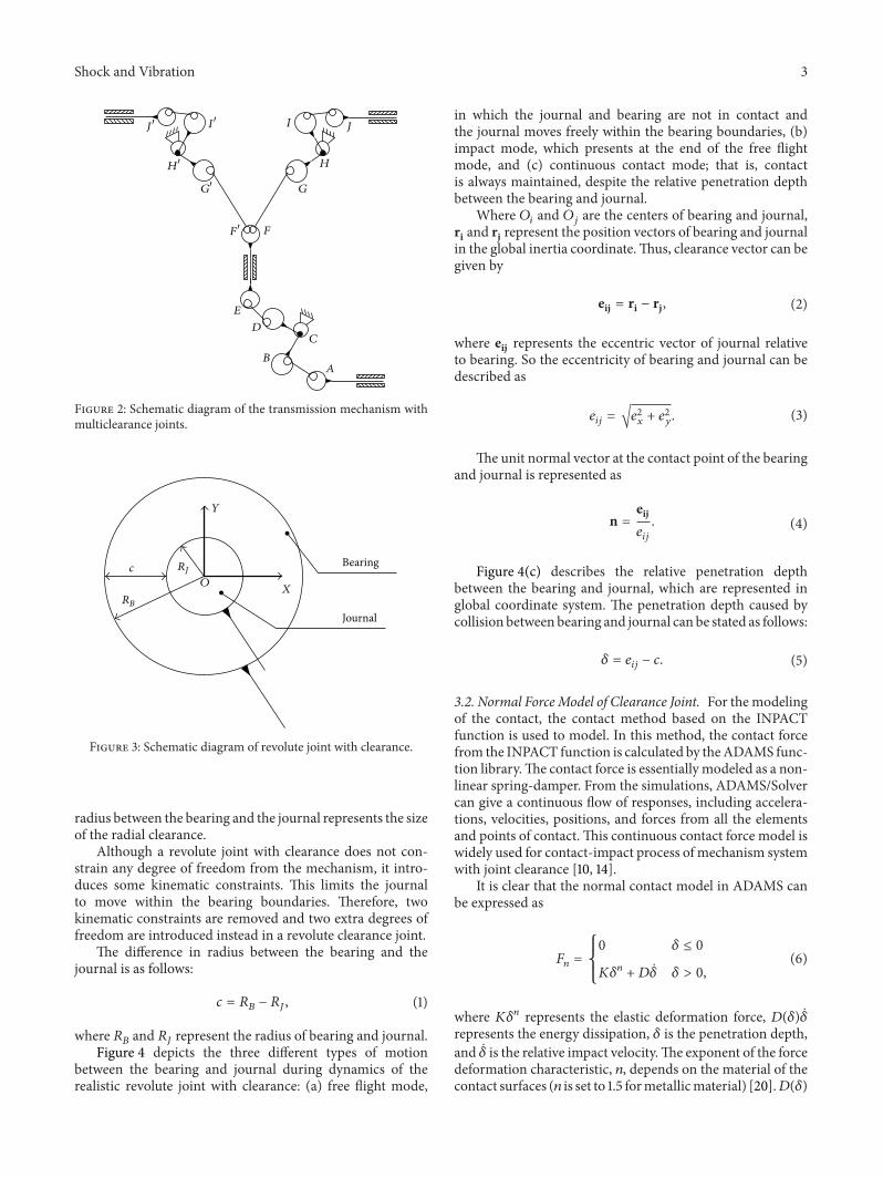
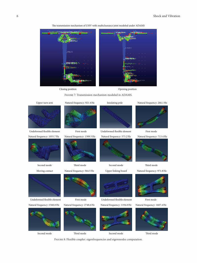
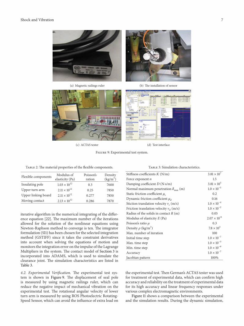
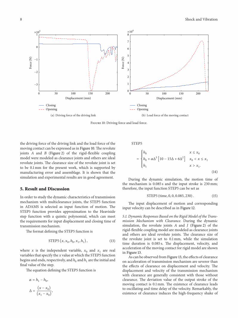
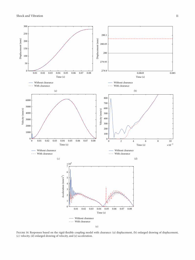
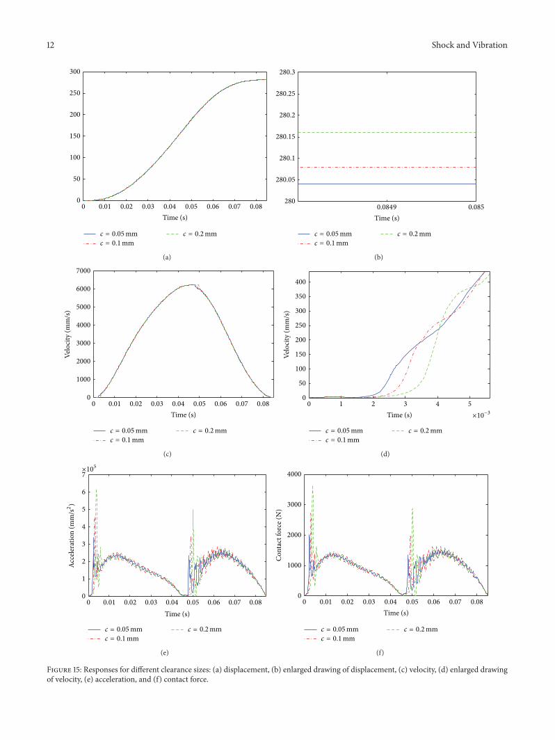

International Journal of
AerospaceEngineeringHindawi Publishing Corporationhttpwwwhindawicom Volume 2014
RoboticsJournal of
Hindawi Publishing Corporationhttpwwwhindawicom Volume 2014
Hindawi Publishing Corporationhttpwwwhindawicom Volume 2014
Active and Passive Electronic Components
Control Scienceand Engineering
Journal of
Hindawi Publishing Corporationhttpwwwhindawicom Volume 2014
International Journal of
RotatingMachinery
Hindawi Publishing Corporationhttpwwwhindawicom Volume 2014
Hindawi Publishing Corporation httpwwwhindawicom
Journal ofEngineeringVolume 2014
Submit your manuscripts athttpwwwhindawicom
VLSI Design
Hindawi Publishing Corporationhttpwwwhindawicom Volume 2014
Hindawi Publishing Corporationhttpwwwhindawicom Volume 2014
Shock and Vibration
Hindawi Publishing Corporationhttpwwwhindawicom Volume 2014
Civil EngineeringAdvances in
Acoustics and VibrationAdvances in
Hindawi Publishing Corporationhttpwwwhindawicom Volume 2014
Hindawi Publishing Corporationhttpwwwhindawicom Volume 2014
Electrical and Computer Engineering
Journal of
Advances inOptoElectronics
Hindawi Publishing Corporation httpwwwhindawicom
Volume 2014
The Scientific World JournalHindawi Publishing Corporation httpwwwhindawicom Volume 2014
SensorsJournal of
Hindawi Publishing Corporationhttpwwwhindawicom Volume 2014
Modelling amp Simulation in EngineeringHindawi Publishing Corporation httpwwwhindawicom Volume 2014
Hindawi Publishing Corporationhttpwwwhindawicom Volume 2014
Chemical EngineeringInternational Journal of Antennas and
Propagation
International Journal of
Hindawi Publishing Corporationhttpwwwhindawicom Volume 2014
Hindawi Publishing Corporationhttpwwwhindawicom Volume 2014
Navigation and Observation
International Journal of
Hindawi Publishing Corporationhttpwwwhindawicom Volume 2014
DistributedSensor Networks
International Journal of