modeling and simulation of a flexible path generation for
TRANSCRIPT
HAL Id: hal-02120830https://hal.utc.fr/hal-02120830
Submitted on 6 May 2019
HAL is a multi-disciplinary open accessarchive for the deposit and dissemination of sci-entific research documents, whether they are pub-lished or not. The documents may come fromteaching and research institutions in France orabroad, or from public or private research centers.
L’archive ouverte pluridisciplinaire HAL, estdestinée au dépôt et à la diffusion de documentsscientifiques de niveau recherche, publiés ou non,émanant des établissements d’enseignement et derecherche français ou étrangers, des laboratoirespublics ou privés.
Modeling and simulation of a flexible path generationfor an electromagnetic smart conveyance surface
T. Dang, M. Bosch-Mauchand, Christine Prelle
To cite this version:T. Dang, M. Bosch-Mauchand, Christine Prelle. Modeling and simulation of a flexible path generationfor an electromagnetic smart conveyance surface. 2016 11th France-Japan & 9th Europe-Asia Congresson Mechatronics (MECATRONICS) /17th Internationall Conference on Research and Education inMechatronics (REM), Jun 2016, Compiègne, France. pp.308-313. �hal-02120830�

Modeling and simulation of a flexible path generation for an electromagnetic smart conveyance surface
T.A.T Dang, M. Bosch-Mauchand, C.Prelle Sorbonne Universités, Université de Technologie de Compiègne
Laboratoire Roberval, UMR UTC-CNRS 7337 Compiègne, France
Abstract— This article presents the modeling of an electromagnetic smart surface and the simulation of the pallets displacement on this smart surface. This smart surface is a conveyance system that consists of a fixed coils platform and moving pallets. The platform is composed of a coil cells matrix, where each cell is independently supplied. It allows to independently move several pallets within the platform on a planar surface along flexible paths. The behavior of the smart conveyance surface is analyzed by the simulation of the dedicated model. This model uses an algorithm developed in order to generate pallet paths even when some disturbances occur such as failure of elementary cells or potential collision of pallets. The simulation of the pallet displacement with disturbance cases is realized to valid this algorithm.
Keywords—smart surface, electromagnetic actuators, modeling and simulation, pallet displacement.
I. INTRODUCTION
Recently, a very active topic has emerged on distributed manipulation surface, often called Smart Surface, used for conveying and positioning micro components with high flexibility. Many researchers have developed different types of distributed manipulation surfaces answering requirements of flexibility and scalability to extend their dimensions [1]. A wide variety of actuation principles for arrayed systems has been proposed including electromagnetic actuators [2], pneumatic actuators [3], and electrostatic actuators [4], etc.
Hence, Nakazawa et al. [2] developed a conveyance pallet with two degrees of freedom moving on a planar coils array thanks to electromagnetic forces. Yahiaoui et al. [3] designed a pneumatic micro conveyor array composed of micro-actuators which can generate oriented air-jets in four directions. The micro conveyor moves an object to a desired position on a planar surface using four electrovalves, each electrovalve being independently controlled. Another two-dimensional micro-conveyor utilizing electrostatic force is proposed by Edo et al. [4]. This conveyor is able to convey an object weighting several milligrams with a pitch of several micrometers.
A smart surface consists of a two dimensional array of elementary cells, these ones being controlled either globally under the control of a centralized supervisor [5-6], or locally in a distributed manner [7-8]. The elementary cells collectively convey several objects in cooperation with each other. As these elementary cells can work independently and simultaneously, a
new reconfiguration of the smart surface is facilitated [1]. The design of a smart surface as defined by [7] [9] is suited for building the conveyance system of the microfactory [10].
At the Roberval Laboratory of the Université de Technologie de Compiègne, different planar displacement systems based on electromagnetic actuation have been developed in order to move micro-objects using pallets [11], [12]. The advantages of such a principle consist in high speed, simple design and low cost. The main idea is to develop flexible transfer system (smart conveyance surface) for microfactory. The smart conveyance surface is based on a matrix structure that allows local activation to ensure low energy consumption. In addition, it allows to simultaneously and independently control several pallets on the same conveyance surface.
The smart conveyance system presented in this paper is composed of several physical elements such as elementary cells and mobile pallets and a control system able to manage flexible trajectories of the pallets. In this paper, we present a model enabling to simulate the behavior of the smart conveyance surface. An algorithm that synthesizes strategies for controlling and coordinating the behavior of pallets is proposed. In particular, a methodology enabling pallets to avoid certain disturbances (i.e. faulty cells or collisions) is presented. Two simulation cases are detailed for illustrating the capability of interacting automatically without any human intervention.
II. ELECTROMAGNETIC SMART CONVEYANCE SURFACE
A. Actuation principe The planar conveyance system presented in this paper
is based on a micro electromagnetic positioning device previously developed and described in [13]. The conveyor surface owns a matrix configuration where each cell of the matrix is a two-dimension layer coils cell, printed on a four layers Printed Circuit Board (PCB) (see Fig.1). The first two layers (layer 1 and layer 2, see Fig.1) of the PCB integrate the two fixed Planar Electric Drive Coils (PEDCs) and layers 3 and 4 are used for the routing and the connections to the external power source as described in [11]. The layer 1 of the elementary coil cell is superimposed to the layer 2 in order to form a two-dimension orthogonal coil cell as shown in Fig.2.
MECATRONICS - REM 2016 June 15-17, 2016
978-1-5090-1787-4/16/$31.00 ©2016 IEEE 308
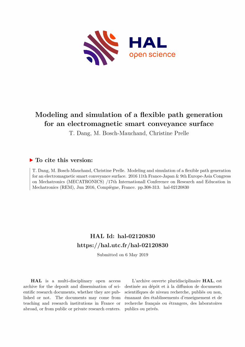
As shown in Fig.1, the pallet is a cross shaped structure with four linear motors (LMs) embedded at the four extremities of the cross structure. The LMs work on the electromagnetic actuation principle based on generation of the Lorentz force. Each LM consists of a Permanent Magnet Array (PMA) made of 14 identical Permanent Magnets (PM) with periodically inverted magnetization oriented along z-axis. Confer to [13] for more details about LM’s design and working principle.
Each elementary coil cell of the matrix can be managed and controlled independently by activating the required coils depending on the position of the pallet. When a PMA is placed
above a powered cell, an electromagnetic force appears due to the magnetic field from the PMA and magnetic field generated from the current crossing the cell. When two sinusoidal currents I1 and I2, with a relative phase shift of π/2, are supplied into the layer 1 of the cells situated underneath the PMAs of the pallets, the pallet translates along x-axis. When the layer 2 of the cells is powered, the pallet moves along y-axis. According to the way the cells are supplied, the pallets can experience a translation or a rotation on the planar surface.
B. Modeling The aim of this section is to state a realistic model of
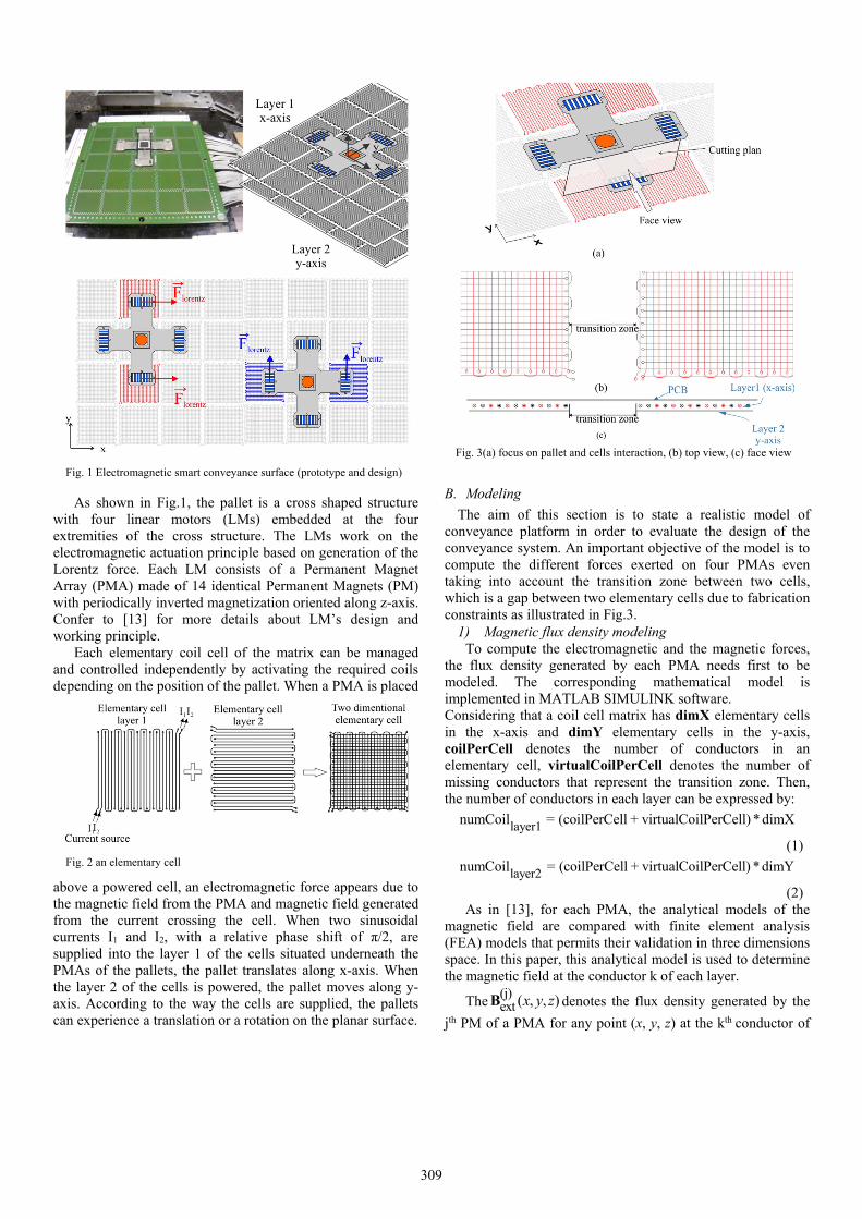
conveyance platform in order to evaluate the design of the conveyance system. An important objective of the model is to compute the different forces exerted on four PMAs even taking into account the transition zone between two cells, which is a gap between two elementary cells due to fabrication constraints as illustrated in Fig.3.
1) Magnetic flux density modeling To compute the electromagnetic and the magnetic forces,
the flux density generated by each PMA needs first to be modeled. The corresponding mathematical model is implemented in MATLAB SIMULINK software. Considering that a coil cell matrix has dimX elementary cells in the x-axis and dimY elementary cells in the y-axis, coilPerCell denotes the number of conductors in an elementary cell, virtualCoilPerCell denotes the number of missing conductors that represent the transition zone. Then, the number of conductors in each layer can be expressed by:
layer1numCoil = (coilPerCell + virtualCoilPerCell) * dimX
(1)
layer2numCoil = (coilPerCell + virtualCoilPerCell) *dimY
(2) As in [13], for each PMA, the analytical models of the
magnetic field are compared with finite element analysis (FEA) models that permits their validation in three dimensions space. In this paper, this analytical model is used to determine the magnetic field at the conductor k of each layer.
The(j)ext ( , , )x y zB denotes the flux density generated by the
jth PM of a PMA for any point (x, y, z) at the kth conductor of
Fig. 1 Electromagnetic smart conveyance surface (prototype and design)
Fig. 2 an elementary cell
Fig. 3(a) focus on pallet and cells interaction, (b) top view, (c) face view
309
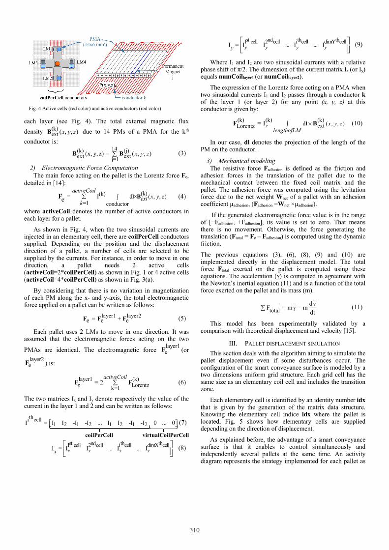
each layer (see Fig. 4). The total external magnetic flux
density (k)ext ( , , )x y zB due to 14 PMs of a PMA for the kth
conductor is:
14(k) (j)
extext j=1(x, y, z) = ( , , )x y zB B (3)
2) Electromagnetic Force Computation The main force acting on the pallet is the Lorentz force Fe,
detailed in [14]:
(k)(k)I d × ( , , )1 conductor
=eactiveCoil
x y zextk =
l BF (4)
where activeCoil denotes the number of active conductors in each layer for a pallet.
As shown in Fig. 4, when the two sinusoidal currents are injected in an elementary cell, there are coilPerCell conductors supplied. Depending on the position and the displacement direction of a pallet, a number of cells are selected to be supplied by the currents. For instance, in order to move in one direction, a pallet needs 2 active cells (activeCoil=2*coilPerCell) as shown in Fig. 1 or 4 active cells (activeCoil=4*coilPerCell) as shown in Fig. 3(a).
By considering that there is no variation in magnetization of each PM along the x- and y-axis, the total electromagnetic force applied on a pallet can be written as follows:
layer1 layer2= +e e eF F F (5)
Each pallet uses 2 LMs to move in one direction. It was assumed that the electromagnetic forces acting on the two
PMAs are identical. The electromagnetic force layer1eF (or
layer2eF ) is:
layer1 (k)e Lorentzk=1
= 2activeCoil
F F (6)
The two matrices Ix and Iy denote respectively the value of the current in the layer 1 and 2 and can be written as follows:
thi cell1 2 1 2 1 2 1 2I = I I -I -I ... I I -I -I 0 ... 0 (7)
coilPerCell virtualCoilPerCell
st nd th th1 cell 2 cell i cell dimX cellI = I I ... I ... Ix x x xx
(8)
st nd th th1 cell 2 cell i cell dimY cellI = I I ... I ... Iy y y yy
(9)
Where I1 and I2 are two sinusoidal currents with a relative phase shift of π/2. The dimension of the current matrix Ix (or Iy) equals numCoillayer1 (or numCoillayer2).
The expression of the Lorentz force acting on a PMA when two sinusoidal currents I1 and I2 passes through a conductor k of the layer 1 (or layer 2) for any point (x, y, z) at this conductor is given by:
(k) (k) (k)d ( , , )extLorentz = Ix x y z
lengthofLM× lF B (10)
In our case, dl denotes the projection of the length of the PM on the conductor.
3) Mechanical modeling The resistive force Fadhesion is defined as the friction and adhesion forces in the translation of the pallet due to the mechanical contact between the fixed coil matrix and the pallet. The adhesion force was computed using the levitation force due to the net weight Wnet of a pallet with an adhesion coefficient µadhesion, (Fadhesion =Wnet ×µadhesion).
If the generated electromagnetic force value is in the range of [−Fadhesion, +Fadhesion], its value is set to zero. That means there is no movement. Otherwise, the force generating the translation (Ftotal = Fe – Fadhesion) is computed using the dynamic friction.
The previous equations (3), (6), (8), (9) and (10) are implemented directly in the displacement model. The total force Ftotal exerted on the pallet is computed using these equations. The acceleration (γ) is computed in agreement with the Newton’s inertial equation (11) and is a function of the total force exerted on the pallet and its mass (m).
total
dvF = mγ = m
dt
(11)
This model has been experimentally validated by a comparison with theoretical displacement and velocity [15].
III. PALLET DISPLACEMENT SIMULATION
This section deals with the algorithm aiming to simulate the pallet displacement even if some disturbances occur. The configuration of the smart conveyance surface is modeled by a two dimensions uniform grid structure. Each grid cell has the same size as an elementary coil cell and includes the transition zone.
Each elementary cell is identified by an identity number idx that is given by the generation of the matrix data structure. Knowing the elementary cell indice idx where the pallet is located, Fig. 5 shows how elementary cells are supplied depending on the direction of displacement.
As explained before, the advantage of a smart conveyance surface is that it enables to control simultaneously and independently several pallets at the same time. An activity diagram represents the strategy implemented for each pallet as
Fig. 4 Active cells (red color) and active conductors (red color)
310
shown in Fig. 6. In this algorithm, an autonomous pallet has 5
main functions with its activities as below:
• getDirection() function: gets the list of indexed cells where the pallet center will pass by. By searching the actual cell index idx where the pallet is located in the list, the next cell is determined. Therefore, if the next cell is idx +1 or idx -1, the pallet will move in the x direction, if the next cell is idx +dimX or idx-dimX, the pallet will move to the y direction. In case that the next cell is idx+dimX+1 (or idx+dimX-1 or idx-dimX+1 or idx-dimX-1), the pallet will move in diagonal direction. Knowing the direction allows determining the elementary cells that needs to be supplied in order to move pallets along a desired
trajectory.
• getSpeed() function gets the amplitude, frequency and phase shift of the two currents that will be sent to an elementary cell.
• cellCommand() function sends command to the cells in the selected direction (e.g.: move forward/ move back in the x or y direction).
• convert2CellIndex() function: converts the coordinates x and y of the pallet center to index idx of the actual cell on which pallet is moving. Due to the matrix configuration of platform, each elementary cell can be identified by the index in the column indxXth and row indxYth of the matrix. The dimensions of matrix are dimX × dimY. Therefore, idx equals indxYth+ indxXth × dimX.
• calculPath() calculates the new path when some disturbances occur such as faulty cells or collisions.
At a given position, each pallet needs to find the shortest path to go to its desired destination. If the pallet detects faulty cells on its trajectory, a new path will be recalculated in order to avoid its LMs passing over faulty cells. Each pallet has a list of elementary cells called security zone. This zone includes all cells locating around the pallet. Two pallets that have at least a common elementary cell in their security zone, will collide or being collided. Therefore, a function “check Collision” allows pallet to predict the collision with other pallets. In order to avoid collision, two pallets first check whether they have the same destination. Then the pallet without priority will change its destination.
IV. TESTING AND VALIDATION
The control algorithms were extensively tested through simulations and evaluated using a Matlab/Simulink model. The two study cases simulate the control of a pallet that moves straight forward from a given initial position to a destination point. For simplification purpose, we consider that rotations are avoided and there is only translation. The desired displacement is achieved by changing the frequency ω of the currents.
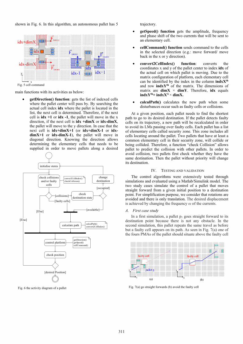
A. First case study In a first simulation, a pallet p1 goes straight forward to its destination point because there is not any obstacle. In the second simulation, this pallet repeats the same travel as before but a faulty cell appears on its path. As seen in Fig. 7(a) one of the fours PMAs of the pallet should situate above the faulty cell
Fig. 6 the activity diagram of a pallet
initialise states
check collisions and/or faulty
cells
change destination
calculate path
check destination state
[occupied]
[collisions]
control platform
[faulty cells]
[available][Else]
check position
[desired Position]
[Else]
getDirection()getSpeed()cellCommand()
calculPath()convert2CellIndex()
conver2CellIndex()checkCollision()
Fig. 5 cell command
Fig. 7(a) go straight forwards (b) avoid the faulty cell
311
if pallet continues moving straight forward. That means there are only 3 LMs working. Therefore it would introduce the dysfunction in the pallet control such as an undesired rotation. Considering that the forces generated by each coil of layer 1 (or layer 2) for moving in the x (y) direction are identical, the velocity of the pallet in the x direction is kept unchanged during the translation. The velocity in the y direction is determined in function of the travel distance and the velocity in the x direction. In the chosen scenario, a faulty cell (identified by a red square) appears on its trajectory. The pallet is capable to detect a faulty cell by asking information of each cell state during its displacement. The aim of this simulation is to verify whether the pallet is able to find a trajectory imposing that a LM, used to move the pallet, never cross the faulty cell and that the pallet reaches the destination point.
Figure 7(b) shows the simulation result. The blue line denotes the position center of the pallet during the displacement. When a faulty cell is detected, the path of the pallet is recalculated to avoid its LMs crossing the faulty cell. In our case, the only possibility to go through the faulty cell is moving in the x direction. Many algorithms exist for graph shortest path identification like Dijkstra’s algorithm, A*, Floyd-Warshall algorithm, etc. The Floyd-Warshall algorithm is used to calculate the new path in this simulation thanks to its rapid deployment in Matlab and the matrix calculation. Finally, the new pallet trajectory finds the shortest paths to reach the destination. The simulated displacement times in Fig. 7(a) and Fig. 7(b) are respectively 6.141s (without faulty cell) and 6.970 s (with faulty cell) to reach the desired destination.
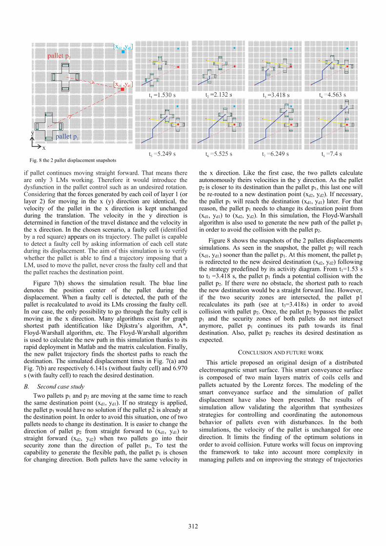
B. Second case study Two pallets p1 and p2 are moving at the same time to reach the same destination point (xd1, yd1). If no strategy is applied, the pallet p1 would have no solution if the pallet p2 is already at the destination point. In order to avoid this situation, one of two pallets needs to change its destination. It is easier to change the direction of pallet p2 from straight forward to (xd1, yd1) to straight forward (xd2, yd2) when two pallets go into their security zone than the direction of pallet p1, To test the capability to generate the flexible path, the pallet p1 is chosen for changing direction. Both pallets have the same velocity in
the x direction. Like the first case, the two pallets calculate autonomously theirs velocities in the y direction. As the pallet p2 is closer to its destination than the pallet p1, this last one will be re-routed to a new destination point (xd2, yd2). If necessary, the pallet p1 will reach the destination (xd1, yd1) later. For that reason, the pallet p1 needs to change its destination point from (xd1, yd1) to (xd2, yd2). In this simulation, the Floyd-Warshall algorithm is also used to generate the new path of the pallet p1 in order to avoid the collision with the pallet p2.
Figure 8 shows the snapshots of the 2 pallets displacements simulations. As seen in the snapshot, the pallet p2 will reach (xd1, yd1) sooner than the pallet p1. At this moment, the pallet p1 is redirected to the new desired destination (xd2, yd2) following the strategy predefined by its activity diagram. From t1=1.53 s to t3 =3.418 s, the pallet p1 finds a potential collision with the pallet p2. If there were no obstacle, the shortest path to reach the new destination would be a straight forward line. However, if the two security zones are intersected, the pallet p1 recalculates its path (see at t3=3.418s) in order to avoid collision with pallet p2. Once, the pallet p2 bypasses the pallet p1 and the security zones of both pallets do not intersect anymore, pallet p1 continues its path towards its final destination. Also, pallet p2 reaches its desired destination as expected.
CONCLUSION AND FUTURE WORK
This article proposed an original design of a distributed electromagnetic smart surface. This smart conveyance surface is composed of two main layers matrix of coils cells and pallets actuated by the Lorentz forces. The modeling of the smart conveyance surface and the simulation of pallet displacement have also been presented. The results of simulation allow validating the algorithm that synthesizes strategies for controlling and coordinating the autonomous behavior of pallets even with disturbances. In the both simulations, the velocity of the pallet is unchanged for one direction. It limits the finding of the optimum solutions in order to avoid collision. Future works will focus on improving the framework to take into account more complexity in managing pallets and on improving the strategy of trajectories
Fig. 8 the 2 pallet displacement snapshots
312
determination. The minimization of the energy consumption could be also a criterion to optimize the control for each pallet.
ACKNOWLEDGMENT
This work is realized under the MICROCOSM project and supported by the Picardie region and co-financed by Europe/FEDER with the European funds for regional developments at the Picardie region of France.
REFERENCES [1] D. El-baz, “A Distributed Algorithm for a Reconfigurable Modular
Surface,” pp. 1591–1598, 2014.
[2] H. Nakazawa , Y. Watanabe and O. Morita, "The two-dimensional micro conveyor: Principles and fabrication process of the actuator", Transducers Digest Int. Conf. on Solid-State Sensors and Actuators, vol. 1, pp. 33-36, 1997
[3] R. Yahiaoui, R. Zeggari, J. Malapert, and J. F. Manceau, “A MEMS-based pneumatic micro-conveyor for planar micromanipulation,” Mechatronics, vol. 22, no. 5, pp. 515–521, 2012.
[4] M. Edo; Y. Watanabe; O. Morita; H. Nakazawa; E. Yonezawa, “Two-dimensional micro conveyer with integrated electrostatic actuators,” IEEE International Conference on Micro Electro Mechanical Systems, pp. 43-48, 1999.
[5] K.F. Böhringer, B.R. Donald and N.C. MacDonald, “Programmable vector fields for distributed manipulation, with applications to MEMS actuator arrays and vibratory parts feeders,” International Journal of Robotics Research 18(2), pp. 168-200,1999.
[6] D.R.W. Barr, D. Walsh, P. Dudek, "A Smart Surface Simulation Environment," IEEE International Conference on Systems, Man, and Cybernetics (SMC), pp.4456,4461, Manchester, 13-16 Oct. 2013.
[7] K. Boutoustous, G. J. Laurent, E. Dedu, L. Matignon, J. Bourgeois, and N. L. Fort-Piat, “Distributed control architecture for smart surfaces,” in
IEEE/RSJ International Conference on Intelligent Robots and Systems, pp.2018–2024 Taipei, Taiwan, October 2010.
[8] Y. Fukuta, Y.A. Chapuis, Y. Mita, H. Fujita, “Design, fabrication, and control of MEMS-based actuator arrays for air-flow distributed micromanipulation,” Journal of Microelectromechanical Systems, VOL. 15, NO. 4, 2006, Pages 912-926
[9] B. Piranda, G. Laurent, J. Bourgeois, C. Clévy, S. Möbesb, N. Fort-Piat, “ A new concept of planar self-reconfigurable modular robot for conveying microparts,” Mechatronics, 23 (October (7)) (2013), pp. 906–915
[10] N. Arora, T. A. T. Dang, L. Petit, M. Bosch-Mauchand, J. Daaboul and C. Prelle, “Contribution to microfactory technologies: A flexible conveyor and its dedicated control system,” 9th International workshop on microfactories, Honolulu, U.S.A, October 5-8, 2014.
[11] N. Arora, M. U. Khan, L. Petit, C. Prelle, “A planar electromagnetic actuator based on two layer coil assembly for micro applications,” IEEE/ASME conference on Advanced Intelligent Mechatronics, Besançon, France, 6 pages, July 8-11,2014.
[12] P. Huyan, J. Xu, L. Petit and C. Prelle, "Modeling and optimization of a digital electromagnetic actuators array," Advanced Intelligent Mechatronics (AIM), 2014 IEEE/ASME International Conference on, Besacon, 2014, pp. 50-55.
[13] M.U. Khan, N. Bencheikh, C. Prelle, F. Lamarque, T. Beutel, S. Büttgenbach, “A long stroke electromagnetic XY positioning stage for micro applications,” IEEE/ASME Transactions on Mechatronics, Vol. 17, Issue 5, pp 866-875, 2012
[14] E. P. Furlani, “Permanent Magnet and Electromechanical Devices Materials, Analysis and Applications,” San Diego, CA: Academic, 2001.
[15] T. A. T. Dang, M. Bosch-Mauchand, N. Arora, C. Prelle, and J. Daaboul, “Electromagnetic modular Smart Surface architecture and control in a microfactory context,” Comput. Ind., 2016, doi:10.1016/j.compind.2016.02.003, in press.
313