research and verification of key techniques in the
TRANSCRIPT
Research ArticleResearch and Verification of Key Techniques in the Simulation ofSpace Extremely Rapid Decompression in Millisecond
Junwei Wang , Lei Zhang , Guohua Li, Ran Liu, Juan Ning, Xiao Han, and Xin He
Beijing Institute of Spacecraft Environment Engineering, Beijing 100094, China
Correspondence should be addressed to Junwei Wang; [email protected]
Received 10 October 2020; Revised 9 February 2021; Accepted 20 March 2021; Published 5 April 2021
Academic Editor: Giovanni Palmerini
Copyright © 2021 Junwei Wang et al. This is an open access article distributed under the Creative Commons Attribution License,which permits unrestricted use, distribution, and reproduction in any medium, provided the original work is properly cited.
The research of rapid decompression with its effect assessment and protection technology is the problem that must be faced by thefuture exploration projects such as near space exploration, deep space exploration, and long-term lunar or Mars base. A newreusable quick opening mechanism which can be opened in millisecond is designed to meet the testing requirement of groundsimulator for extremely rapid decompression, and the testing results show that the quick opening mechanism can be openedwithin 0.1 s. The mathematical formulation is also developed, and the comparisons with the results from the literaturedemonstrate its validity. The CFD simulation and the verification system are established for the airflow in the rapiddecompression process under different opening degrees. The simulation results show that the effect of the opening on thedecompression process is very obvious and the decompression time corresponding to 50%, 75%, and 100% opening is 479.1ms,320.7ms, and 290.1ms, respectively. The testing results also show a consistent trend which is 583ms, 450ms, and 384ms,respectively, to reach the equilibrium state.
1. Introduction
The current research on the rapid decompression focuses onthe aeronautics and astronautics field. The research emphasisin the aviation field mainly is the verification of design, per-formance, and reliability for aircraft and airborne equipmentunder high altitude decompression environment. In thespace field, research institutions represented by NASA havecarried out a lot of studies on the rapid decompression thatmay occur in the space environment, such as the space shut-tle and the space station, and guided the design and verifica-tion of spacecraft, spacesuit, and Environmental Control andLife Support System (ECLSS) for astronaut [1–7].
The rarefied gas flow in space decompression process canbe studied by approximate simplified calculation or numeri-cal simulation. Eoffrey established a numerical model for thepressure drop process of exposed vacuum [8]. Pagani andCarrera developed a zero-dimensional mathematical formu-lation for rapid and explosive decompression analyses ofpressurized aircraft. The numerical procedure based on Eulerintegration scheme had also been discussed for multicom-partment aircraft analysis [9]. Bréard et al. modeled and ana-
lyzed the sudden decompression of an airliner cockpit with ahardened cockpit door installed using the CFD code [10].Gao et al. from Beijing University of Aeronautics and Astro-nautics put forward the technology of prevacuum chamber torealize the simulated rapid decompression and deduced themathematical equation of the airflow balance between theprevacuum chamber and testing chamber combining withthe flow conduction equation and gas thermodynamicstheory [11].
Many kinds of facility have been built for the groundsimulation of rapid decompression in China and otherresearch institutions. The Johnson Space Center in theUnited States designed an additional chamber as a rapiddecompression chamber next to its 20-foot diameter thermalvacuum chamber and completed the product verificationtesting such as high-pressure tank and airbag [12]. Theresearch institutions such as the Institute of Aviation Medi-cine and Astronaut Training Center in China have also builtsimilar rapid decompression facility. The rapid decompres-sion system of the Astronaut Training Center consists ofthe main chamber and the auxiliary chamber. The length ofthe cylinder of the main chamber is 3m, and its volume is
HindawiInternational Journal of Aerospace EngineeringVolume 2021, Article ID 6634468, 11 pageshttps://doi.org/10.1155/2021/6634468

about 50m3. The length of the auxiliary chamber is 2m, andthe volume is 12.5m3. During the testing of rapid decompres-sion, the main chamber is prevacuum chamber and aDN320mm vacuum pipeline is used for releasing channel withfour DN150mm electromagnetic valves. The rapid decom-pression rate of the system is better than that of 13.3 kPa/s.Yi Dongchen from the Institute of Aviation Medicine hasdeveloped a compound environment facility with the functionof rapid decompression, which is used for the evaluation ofaeronautic equipment and the scientific research training ofaviation medicine. The quick opening mechanism adoptedcompressed air as the power, and the pneumatic power is con-verted to hydraulic power through the accumulator to pushthe motion of piston rod in hydraulic cylinder [13]. In cooper-ation with the Beijing Institute of Spacecraft EnvironmentalEngineering, Harbin Institute of Technology completed abrand-new principle design of the quick opening mechanism,which is realized by utilizing a spring-based release mecha-nism to instantly convert large amounts of elastic potentialenergy into kinetic energy [14, 15].
Based on the investigation of the research status, consider-ing the further improvement of the requirements for accuratesimulation of space extremely rapid decompression, it is inurgent need of a reusable quick opening mechanism with highreliability that can be opened within the range of millisecondsto meet the research and verification requirements of spaceextremely rapid decompression process. The research hasbeen presented in Section 2. The methods of calculation andnumerical simulation also need further study in order to getmore accurate results, which are discussed in Sections 3 and4. The testing verification is shown in Section 5, and theconclusions are summarized at the end of the paper.
2. Design of the Quick Opening Mechanism
Quick opening mechanism is the key equipment for theground simulation of extremely rapid decompression environ-ment. The design of the mechanismmainly faces the followingdifficulties:
(1) Quick opening speed: for the extremely rapid decom-pression, the whole time is 0.1 s generally to finish thewhole decompression process, so it requires that themechanism should achieve the full opening within0.1 s or even faster
(2) Vacuum sealing: the quick opening mechanism isinstalled between the high-pressure chamber and thelow-pressure chamber. The mechanism should be ableto withstand huge reverse pressure difference beforethe test, especially to the large quick openingmechanism
(3) Reusable and reliable: due to the huge pressure differ-ence and the extremely fast opening speed, the partsof the quick opening mechanism will bear a greatimpact force, so the mechanism design should bewith high reliability even after multiple uses
For the requirement of extremely rapid decompressionenvironment on ground, a new type of reusable quick open-
ing mechanism is designed in the paper which can achieveinstantaneous open between the prevacuum chamber andtesting chamber. The mechanism comprises a valve unit, areleasing unit, a closing unit, and an energy storage unit;the specific structure of which is shown in Figure 1.
When the mechanism is closing, the traction cylinder ofthe closing unit moves downward to push the ejector rodand the trailed disc moving downward in a straight line.Meanwhile, the spring of the energy storage unit achievesstretching energy storage. After the traction cylinder movesdownward in place, the cover plate can be rotated to theclosed position so that the bearing of the releasing unit ispressed above the cover plate. At this time, the bearing,cover plate, ejector rod, and sealing plate are transferred tothe downward force to realize the closure of the mechanism.The pretightening force of sealing plate can be adjusted byrotating the hand wheel until the mechanism is completelyclosed and then lift the traction cylinder of the closing unitupward to its original position. When the mechanism needsto be opened, the electromagnetic actuator drives the bearingto retract at tremendous speed so that the bearing no longerexerts pressure on the cover plate. At this time, the ejectorrod and the sealing plate lose the pressure of the cover plate.Due to the superposition of atmospheric pressure on thesealing plate and the stretching energy storage of springs,the sealing plate can complete the upward movement andachieve open in milliseconds. When the trailed disc movesto the damping block, the resistance stops to complete theopening action of the whole mechanism.
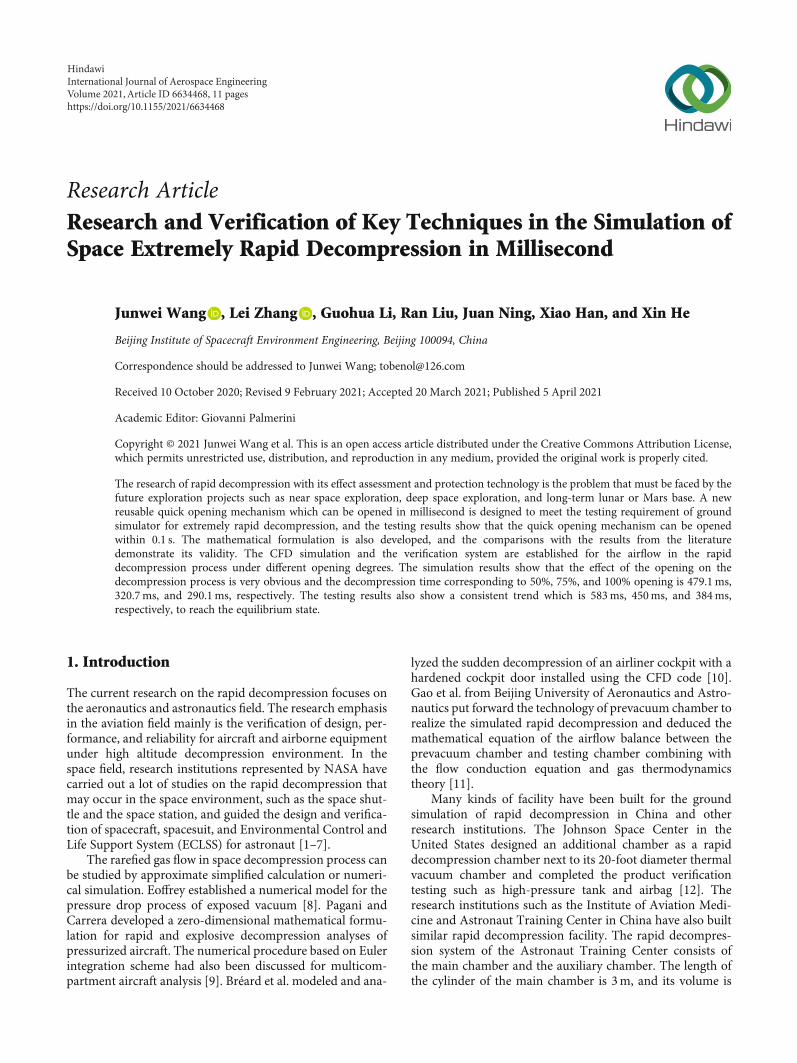
The strength of the mechanism was analyzed by finiteelement method using ANSYS. The input parameters of thesimulation are shown in Table 1, and the force analysis ofthe quick opening mechanism is shown in Figure 2. Theresults indicated that the von Mises stress did not exceedthe maximum tension value, and the structure of the mecha-nism met the safety requirements.
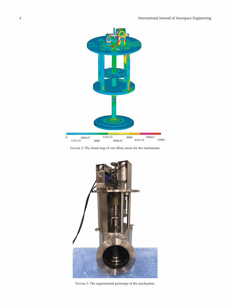
The prototype of the mechanism is shown in Figure 3.Before the testing of the rapid decompression, two connect-ing flanges of the quick opening mechanism are, respectively,installed on the testing chamber and prevacuum chamber.Close the mechanism according to the above operationsequence, pump the testing chamber and prevacuum reservechamber to the required pressure, and then open the quickopening mechanism to achieve the rapid decompression.
The designed quick opening mechanism has the follow-ing beneficial characteristics:
(1) Due to the superposition of atmospheric pressure onthe sealing plate and the stretching energy storage ofsprings, the mechanism can be opened within themagnitude of milliseconds
(2) In addition, the strength can be changed through thereplacement of spring strength subsequently, so as toachieve the function of adjusting the opening time
(3) The welded bellows are used to complete the sealingof shaft, and the whole mechanism has no dynamicsealing structure
2 International Journal of Aerospace Engineering

(4) The cylinder is equipped to complete the auxiliaryclosing of the mechanism, and electromagnetic actu-ator is used to complete the opening action of themechanism with high degree of automation
(5) The linear motion mode of the sealing plate of themechanism is more reliable, simpler in structure,and more powerful in function
3. Mathematical Model
Rapid decompression is a typical problem of inflating anddeflating for rigid chambers. The process of inflating anddeflating is rapid, and the heat exchange between the systemand the outside world can be ignored. The temperature vari-ation and the nonuniformity of pressure and temperature ofeach module are also ignored. The calculation formula of air-flow through the quick opening mechanism is
m⋅ = CdAp1ffiffiffiffiffiffiffiffi
RT1p f p1, p2ð Þ, ð1Þ
where
f p1, p2ð Þ =
ffiffiffiffiffiffiffiffiffiffiffiffiffiffiffiffiffiffiffiffiffiffiffiffiffiffiffiffiffiffiffiffiffiffiffiffiffiffiffiffiffiffiffiffiffiffiffiffiffiffiffiffiffiffiffiffiffiffiffiffi2γγ − 1
p2p1
� �2/γ−
p2p1
� � γ+1ð Þ/γ" #
,
vuut p2p1
> 2γ + 1
� �γ/ γ−1ð Þ,
ffiffiffiffiffiffiffiffiffiffiffiffiffiffiffiffiffiffiffiffiffiffiffiffiffiffiffiffiffiffiffiffiffiffiffiffi
γ2
γ + 1
� � γ+1ð Þ/ γ−1ð Þs
, p2p1
≤2
γ + 1
� �γ/ γ−1ð Þ:
8>>>>>><
>>>>>>:
ð2Þ
The calculation of the pressure and temperature of thetesting chamber can be obtained from the first law of thermo-dynamics and the Ideal Gas Equation as follows.
The pressure variation formula of the testing chamber
dp1dt
= −γRT1m
⋅1
V1: ð3Þ
The temperature variation formula of the testing chamber
T1T1,0
= p1p1,0
� � γ−1ð Þ/γ: ð4Þ
The lumped parameter method was used to model theconnecting pipeline for decompression, and the heat transferof gas flow in the process was not considered. Assuming thatthe velocity, pressure, and temperature of the connecting pipe-line were uniformly distributed, the calculation formula of thepressure variation with time of the connecting pipeline in theprocess of decompression was as follows:
dp2dt
=γRT1 m
⋅1 −m
⋅2
� �
V2, ð5Þ
where m⋅1 and m2
⋅ are the mass flow rates of the inflow andoutflow pipelines, respectively.
Valve unit
Releasing unit
Closing unit &
Energy storageunit
Traction cylinder
Ejector rodTrailed disc
Spring
Cover plate
Bearing
Sealing plate
Hand wheel
Electromagneticactuator
Damping block
Connectingflange
Figure 1: The specific structure of quick opening mechanism.
Table 1: List of input parameters.
Input parameters Value
Atmospheric pressure 101.3 kPa
Pressure of O-ring 200.0 kPa
Vacuum pressure 1.0 kPa
Traction of single spring 100N
Friction coefficient 0
Mesh quantity 1225469
3International Journal of Aerospace Engineering
01333.33
2666.674000
5333.336666.67
80009333.33
10666.712000
Figure 2: The cloud map of von Mises stress for the mechanism.
Figure 3: The experimental prototype of the mechanism.
4 International Journal of Aerospace Engineering
Similarly, the calculation formula of the pressure andtemperature of the prevacuum chamber can be obtained asfollows.
The pressure variation formula of the prevacuum chamber
dp3dt
= γRT1 m2⋅
V3: ð6Þ
The temperature variation formula of the prevacuumchamber
T3,t+1T3,t
= γ
T3,t/T1,t+1ð Þ + γ − T3,t/T1,t+1ð Þð Þ p3,t/p3,t+1� � : ð7Þ
The rapid decompression process can be calculated andanalyzed through the above calculation formula. This paper
0 10 20 30 40 50 60 70
0
20000
40000
60000
80000
100000
2.9in.3.8in.5.0in.
6.5in.9.0in.24.0in.
Decompression time (s)
Pres
sure
of t
he C
rew
Mod
ule (
Pa)
Figure 4: The decompression time under different hole size for Crew Module.
0.0 0.1 0.2 0.3 0.4 0.5 0.6 0.7
0
20000
40000
60000
80000
100000
50%
100%75%
Decompression time (s)
Pres
sure
of t
he te
sting
cham
ber (
Pa)
Figure 5: The pressure variation of testing chamber under different openings.
5International Journal of Aerospace Engineering

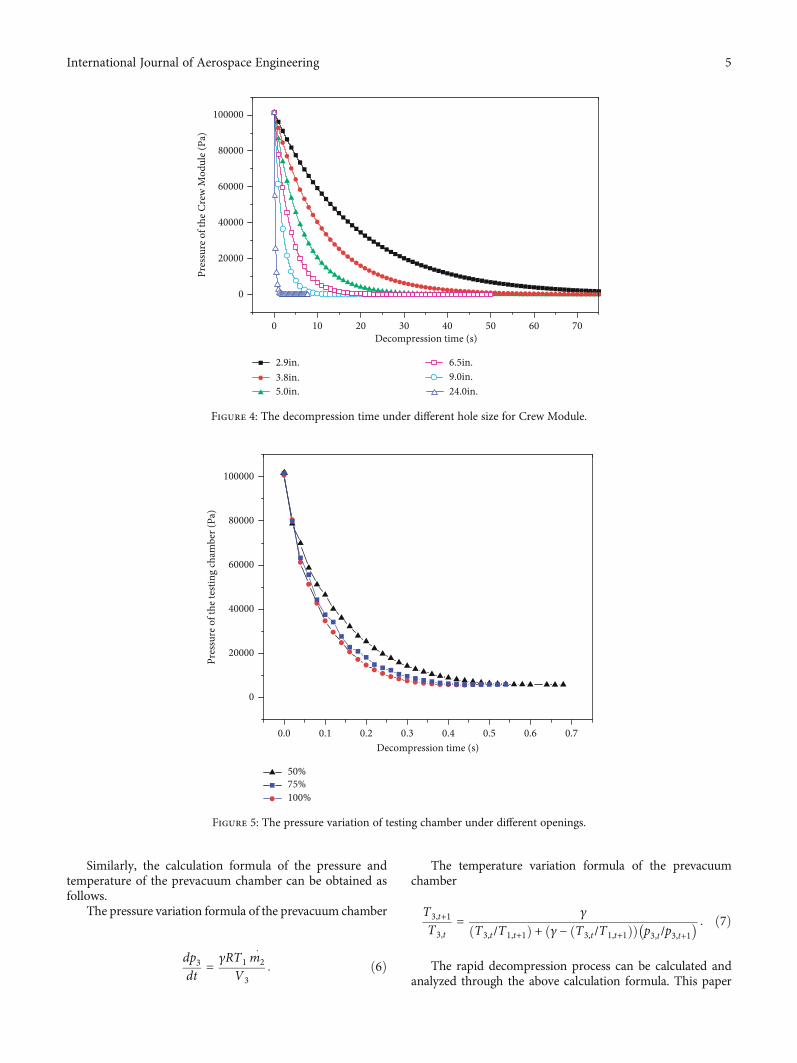
verifies the validity of the calculation through similar literaturecases. In reference [16], NASA studied the safety assessment ofthe next-generation Multipurpose Crew Vehicle (MPCV)under the different decompression processes and summarizedthe estimated time for Crew Module depressurization as afunction of the effective hole size. The formula in this paperis used to recalculate and verify the decompression time underthe same conditions with a 550 ft3 cabin volume at standardatmospheric pressure. The specific calculation results are
shown in Figure 4. The comparisons with the results fromthe literature demonstrate the validity of the calculationmethod, which can be also applied, with no lack of accuracy,to the decompression analysis of spacecraft.
4. CFD Simulation
In order to study the airflow characteristics in the rapiddecompression process more intuitively, the FLUENT which
0.0 0.1 0.2 0.3 0.4 0.5 0.6
0
100
200
300
400
500
600
Time (s)
0
100
200
300
400
500
600
Exit
velo
city
of t
estin
g ch
ambe
r (m
/s)
Inle
t vel
ocity
of p
re-v
acuu
m ch
ambe
r (m
/s)
50%75%100%
(a)
0.000 0.001 0.002 0.003 0.004 0.005 0.006 0.007 0.008 0.009
0
100
200
300
400
500
600
700
50%75%100%
Time (s)
Exit
velo
city
of t
estin
g ch
ambe
r (m
/s)
Inle
t vel
ocity
of p
re-v
acuu
m ch
ambe
r (m
/s)
0
100
200
300
400
500
600
700
(b)
Figure 6: The change of average velocity under different openings.
6 International Journal of Aerospace Engineering
(a) The distribution of flow field under 100% opening of gate valve (30ms)
(b) The distribution of flow field under 100% opening of gate valve (290ms)
(c) The distribution of flow field under 75% opening of gate valve (30ms)
(d) The distribution of flow field under 75% opening of gate valve (321ms)
(e) The distribution of flow field under 50% opening of gate valve (30ms)
(f) The distribution of flow field under 50% opening of gate valve (479ms)
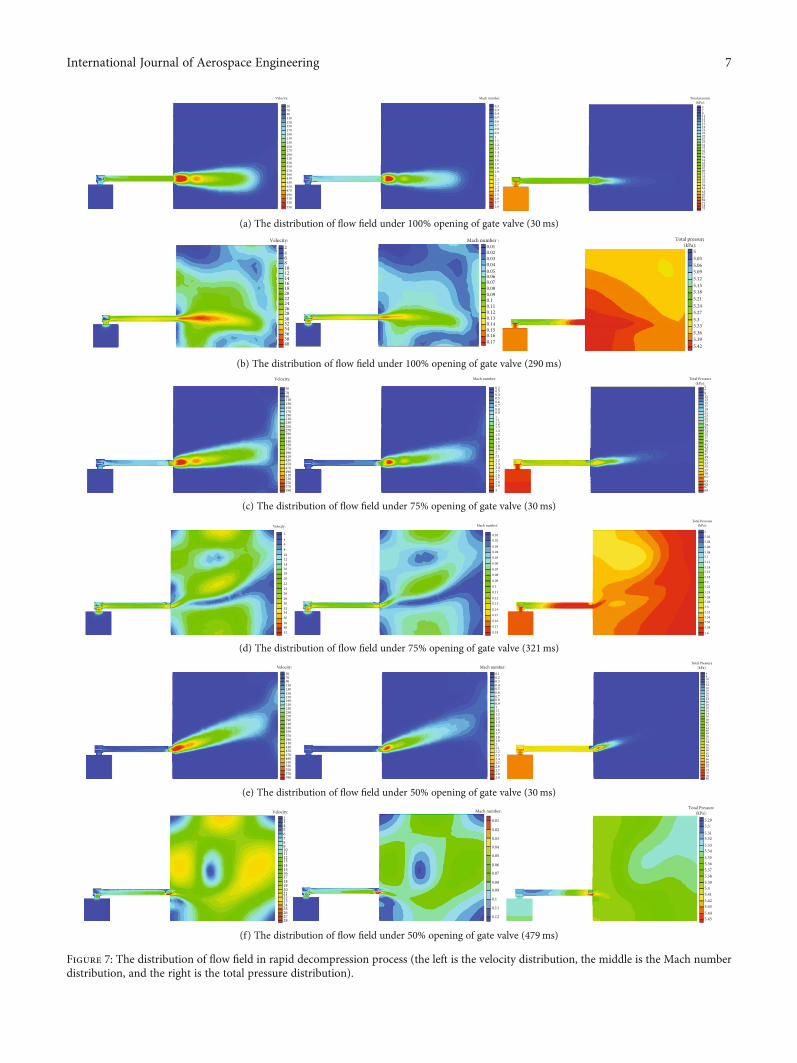
Figure 7: The distribution of flow field in rapid decompression process (the left is the velocity distribution, the middle is the Mach numberdistribution, and the right is the total pressure distribution).
7International Journal of Aerospace Engineering
is a commercial CFD software is used to simulate the pres-sure changes in chambers. The model was divided into twochambers with a volume of 0.2m3 and 14m3, respectively.The DN150 decompression pipeline with a length of 1mwas equipped with a quick opening mechanism and aDN150mm vacuum gate valve that can be opened under100%, 75%, and 50% opening, respectively. The details suchas the sealing plate of the mechanism and the valve plate ofthe gate valve also are modeled considering the flow coeffi-cient to get the better simulation accuracy.
The model structure discretizes the calculation area withpolyhedral unstructured grids, sets boundary layer grids forthe inside of the pipeline. Discrete RANS (Reynolds AverageNavier-Stokes) equation based on finite volume method andk - ω turbulence model is adopted. The initial value of thetesting chamber pressure is 101.325 kPa, and the initial valueof the prevacuum chamber pressure is set as 4 kPa.
4.1. The Pressure Change of Testing Chamber. The variationtrend of pressure in the testing chambers is shown inFigure 5, where the pressure is the absolute pressure at thegeometric center point of each chamber. It can be seen thatdifferent valve openings have a significant influence on thedecompression process, and the smaller the opening is, themore obvious it is. Decompression time corresponding to50%, 75%, and 100% opening degree is 479.1ms, 320.7ms,and 290.1ms, respectively.
4.2. The Velocity Change of Testing Chamber. More detailscan be obtained through analysis of decompression velocity.Take the average velocity of the exit section of the testingchamber and the inlet section of the prevacuum chamber,and observe the variation trend of these two average veloci-ties, as shown in Figure 6, where Figure 6(a) is the overallvariation trend and Figure 6(b) is the velocity variation detailof the first 9ms. The line with the same symbol in the figurerepresents the working condition of the valve under the sameopening. The black line is the average outlet velocity of the
testing chamber, the blue line is the average inlet velocity ofthe prevacuum chamber, and the red dotted line is zero.
As shown in Figure 6(a), the smaller the valve opening is,the corresponding exit velocity of testing chamber is smaller,and the inlet velocity of prevacuum chamber is greater. Thereason for this is that the baffle of valve increases the flowresistance, increases the expansion ratio, and reduces theentrance density of the prevacuum chamber, which leads tothe decrease of the outlet velocity of the testing chamberand the increase of the inlet velocity of the prevacuum cham-ber at the same time. All the curves on the right of the figuredrop below the red dotted line and show negative values,indicating that there is a phenomenon of reverse flow at thistime, and there is a slight iteration when the flow reaches theequilibrium state. It can be seen from Figure 6(b) that theflow velocity curve at the outlet of the testing chamber almostcoincides at the initial stage. This is due to the fact that theback of the quick opening mechanism in the pipeline is insupersonic flow, and the flow state is only related to theparameters of inlet flow, and the opening of the gate valvehas no influence on it. The inlet velocity of the prevacuumchamber remains zero at the first 3ms. This is because theincoming flow propagates in the pipeline in the form of shockwave. However, it reaches a high velocity immediately with thehighest points being 634.8m/s, 547.7m/s, and 458.6m/s,respectively.
4.3. The Distribution of Flow Field. The opening of gate valvehas an obvious influence on the flow field. Figure 7 shows thedistribution of flow field under the different opening condi-tions. It can be seen that the sealing plate of the quick open-ing mechanism bears the impact of air flow, and there is acertain pressure difference on both sides. However, the totalpressure drop of the pipeline is close to the ideal state anddoes not increase significantly. There is turbulence aroundthe quick opening mechanism, and the flow field is complex.The flow is fully developed after a long pipeline. Under thecondition of 75% opening of the gate valve, there is a signif-icant pressure difference between the front and back of thevalve and a significant change in the direction of jet flowand the flow field of the gate valve is obviously influenced.The influence of flow field is more obvious under the condi-tion of 50% opening. The pressure difference before and afterthe gate valve becomes the most important pressure dropinside the pipeline. The gas appears obvious step-downexpansion here, and the deflection of jet direction is veryobvious.
5. Testing Verification
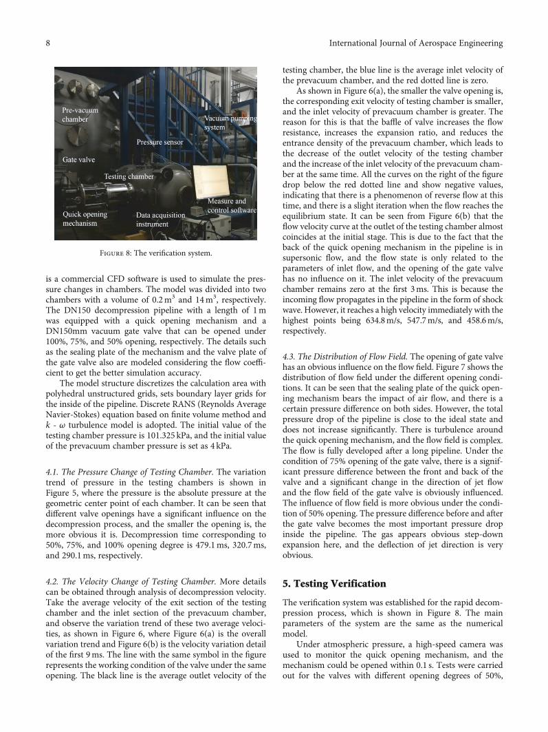
The verification system was established for the rapid decom-pression process, which is shown in Figure 8. The mainparameters of the system are the same as the numericalmodel.
Under atmospheric pressure, a high-speed camera wasused to monitor the quick opening mechanism, and themechanism could be opened within 0.1 s. Tests were carriedout for the valves with different opening degrees of 50%,
Figure 8: The verification system.
8 International Journal of Aerospace Engineering

Pres
sure
of t
he te
sting
cham
ber (
Pa)
Testing dataSimulation data
0.0 0.1 0.2 0.3 0.4
0
20000
40000
60000
80000
100000
Decompression time (s)
(a) 100% opening of gate valve
Testing dataSimulation data
Pres
sure
of t
he te
sting
cham
ber (
Pa)
0.0 0.1 0.2 0.3 0.4 0.5
0
20000
40000
60000
80000
100000
Decompression time (s)
(b) 75% opening of gate valve
Figure 9: Continued.
9International Journal of Aerospace Engineering
75%, and 100%, respectively, which needs 583ms, 450ms,and 384ms, respectively, to reach the equilibrium state.
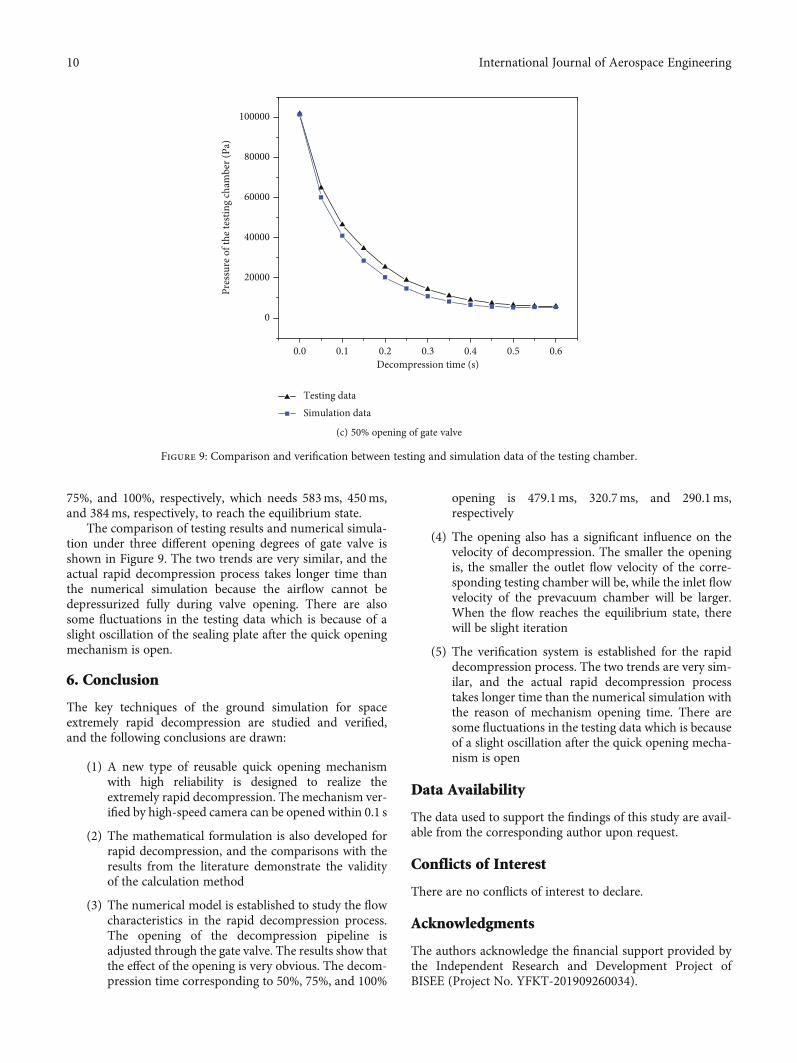
The comparison of testing results and numerical simula-tion under three different opening degrees of gate valve isshown in Figure 9. The two trends are very similar, and theactual rapid decompression process takes longer time thanthe numerical simulation because the airflow cannot bedepressurized fully during valve opening. There are alsosome fluctuations in the testing data which is because of aslight oscillation of the sealing plate after the quick openingmechanism is open.
6. Conclusion
The key techniques of the ground simulation for spaceextremely rapid decompression are studied and verified,and the following conclusions are drawn:
(1) A new type of reusable quick opening mechanismwith high reliability is designed to realize theextremely rapid decompression. The mechanism ver-ified by high-speed camera can be opened within 0.1 s
(2) The mathematical formulation is also developed forrapid decompression, and the comparisons with theresults from the literature demonstrate the validityof the calculation method
(3) The numerical model is established to study the flowcharacteristics in the rapid decompression process.The opening of the decompression pipeline isadjusted through the gate valve. The results show thatthe effect of the opening is very obvious. The decom-pression time corresponding to 50%, 75%, and 100%
opening is 479.1ms, 320.7ms, and 290.1ms,respectively
(4) The opening also has a significant influence on thevelocity of decompression. The smaller the openingis, the smaller the outlet flow velocity of the corre-sponding testing chamber will be, while the inlet flowvelocity of the prevacuum chamber will be larger.When the flow reaches the equilibrium state, therewill be slight iteration
(5) The verification system is established for the rapiddecompression process. The two trends are very sim-ilar, and the actual rapid decompression processtakes longer time than the numerical simulation withthe reason of mechanism opening time. There aresome fluctuations in the testing data which is becauseof a slight oscillation after the quick opening mecha-nism is open
Data Availability
The data used to support the findings of this study are avail-able from the corresponding author upon request.
Conflicts of Interest
There are no conflicts of interest to declare.
Acknowledgments
The authors acknowledge the financial support provided bythe Independent Research and Development Project ofBISEE (Project No. YFKT-201909260034).
0.0 0.1 0.2 0.3 0.4 0.5 0.6
0
20000
40000
60000
80000
100000
Decompression time (s)
Pres
sure
of t
he te
sting
cham
ber (
Pa)
Testing dataSimulation data
(c) 50% opening of gate valve
Figure 9: Comparison and verification between testing and simulation data of the testing chamber.
10 International Journal of Aerospace Engineering

References
[1] N. E. Daidzic and M. P. Simones, “Aircraft decompressionwith installed cockpit security door,” Journal of Aircraft,vol. 47, no. 2, pp. 490–504, 2010.
[2] K. Curry and K. Prokhorov, “International Space Station (ISS)responses to rapid depressurization,” in Proceedings of the32nd International Conference on Environmental Systems,2002-01-2493, San Antonio, Texas, July 2002.
[3] J. D. Pratt, “Rapid decompression of pressurized aircraft fuse-lages,” Journal of Failure Analysis and Prevention, vol. 6,pp. 70–74, 2006.
[4] J. F. Lu, L. Li, and L. Chen, “Study on the decompression timeof the hypobaric rapid decompression chamber,” InternationalJournal of Heat and Technology, vol. 33, no. 2, pp. 75–78, 2015.
[5] G. Cable, “In-flight hypoxia incidents in military aircraft:causes and implications for training,” Aviation, Space, andEnvironmental Medicine, vol. 74, no. 2, pp. 169–172, 2003.
[6] J. Bai, X. Chen, J. Yang, and S. Yang, “Simulation of aircraftcabin pressure loss,” Journal of Civil Aviation University ofChina, vol. 32, no. 6, pp. 1–6, 2014.
[7] X. Song and B. Zai, “Low pressure test standard and test tech-nical analysis,” Environmental Technology, vol. 6, pp. 94–97,2014.
[8] A. Eoffrey, “Mathematical model research of human exposureto vacuum,” Journal of the British Interplanetary Society,vol. 29, no. 2, pp. 148–154, 2008.
[9] A. Pagani and E. Carrera, “Gas dynamics of rapid and explo-sive decompressions of pressurized aircraft including activeventing,” Advances in Aircraft and Spacecraft Science, vol. 3,no. 1, pp. 77–93, 2016.
[10] C. Bréard, D. Lednicer, N. Lachendro, and E. Murvine, “ACFD analysis of sudden cockpit decompression,” in 42ndAIAA Aerospace Science Meeting and Exhibit, AIAA-2004-0054, Reno, USA, January 2004.
[11] H. Gao, M. Liu, and J. Wang, “Novel technique to rapidlypump spacecraft cabin with negatively pressured cabin andits theoretical basis,” Journal of Vacuum Science and Technol-ogy, vol. 33, no. 12, pp. 1191–1198, 2013.
[12] S. E. Jacobs, “Quantification of the dynamic pressure responsein a pressure suit during a rapid cabin decompression,” in 43rdInternational Conference on Environmental Systems, AIAA2013-3397, Vail, CO, July 2013.
[13] D. Yin, H. Xiao, and B. Zhang, “Development of experimentchambers of complex low-pressure environment,” ChineseMedical Equipment Journal, vol. 42, no. 1, pp. 6–12, 2011.
[14] L. Zhang, X. Han, X. B. Zhang, and J. H. Yan, “Door-triggeringmechanism for large-scale rapid-decompression experiments,”International Journal of Aerospace Engineering, vol. 2020, Arti-cle ID 6841651, 9 pages, 2020.
[15] X. Han, W. Leng, and S. Z. Lv, “Design of fast pressure reliefmechanism for fast pressure relief environment simulationequipment,” Spacecraft Environment Engineering, vol. 36,no. 4, pp. 387–392, 2019.
[16] M. J. Sargusingh, “MPCV flight suit performance after anuncontrolled crew cabin depressurization event,” in 42ndInternational Conference on Environmental Systems, AIAA2012-3644, San Diego, California, July 2012.
11International Journal of Aerospace Engineering