refining technology presentation
TRANSCRIPT
8/8/2019 Refining Technology Presentation
http://slidepdf.com/reader/full/refining-technology-presentation 1/41
Introduction toPetroleum Refinery
Processing
Dr.G.Balachandran
1
8/8/2019 Refining Technology Presentation
http://slidepdf.com/reader/full/refining-technology-presentation 2/41
Course outliney 1.Introduction to the Refinery Flow sheet
y
2.Hydrocarbon chemistry y 3.Crude oil:Properties,tests,sources,Assays
y 4.Fuel ProductsMTBE
y 5.Atmospheric and vaccum distillation
y
6.FCC(Fluid catalytic cracking)y 7.Catalytic Reforming and aromatics recovery
y 8.Isomerisation,Alkylation and Polymerisation
y 9.Hydroprocessing of sulfur,nitrogen and aromatics
reductiony 10.Sweetening and sulphur recovery.
y 11.Residual processing.Coking,Hydrocracking etc,.
y 12.Refinery operations for tomorrows fuel.
y 13.Future Refinery configurations. 2

8/8/2019 Refining Technology Presentation
http://slidepdf.com/reader/full/refining-technology-presentation 3/41
1.Introduction to the Refinery Flow sheet
3

8/8/2019 Refining Technology Presentation
http://slidepdf.com/reader/full/refining-technology-presentation 4/41
8/8/2019 Refining Technology Presentation
http://slidepdf.com/reader/full/refining-technology-presentation 5/41
5
8/8/2019 Refining Technology Presentation
http://slidepdf.com/reader/full/refining-technology-presentation 6/41
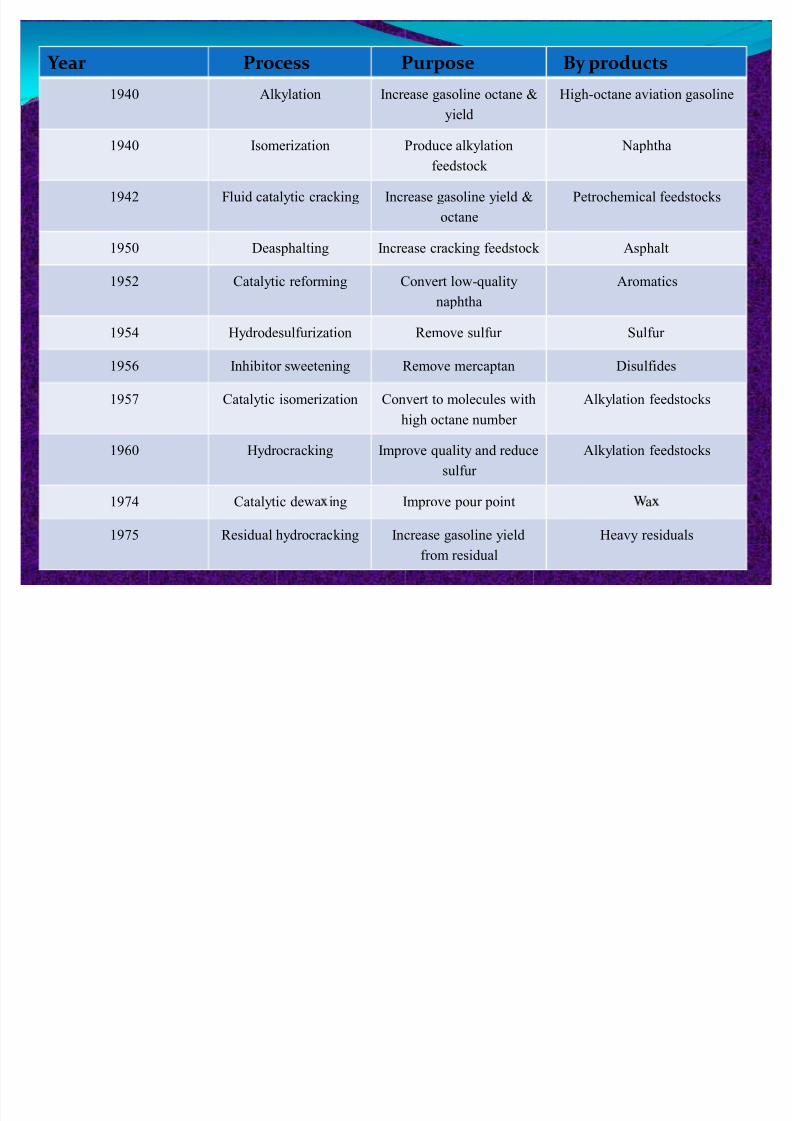
Y ear Process Purpose By products
1940 Alkylation Increase gasoline octane &
yield
High-octane aviation gasoline
1940 Isomerization Produce alkylation
feedstock
Naphtha
1942 Fluid catalytic cracking Increase gasoline yield &
octane
Petrochemical feedstocks
1950 Deasphalting Increase cracking feedstock Asphalt
1952 Catalytic reforming Convert low-quality
naphtha
Aromatics
1954 Hydrodesulfurization Remove sulfur Sulfur
1956 Inhibitor sweetening Remove mercaptan Disulfides
1957 Catalytic isomerization Convert to molecules with
high octane number
Alkylation feedstocks
1960 Hydrocracking Improve quality and reduce
sulfur
Alkylation feedstocks
1974 Catalytic dewa ing Improve pour point a
1975 Residual hydrocracking Increase gasoline yield
from residual
Heavy residuals
6
8/8/2019 Refining Technology Presentation
http://slidepdf.com/reader/full/refining-technology-presentation 7/41
y Crude oil is a mixture of hydrocarbon molecules, which are organic compounds of carbon and hydrogenatoms that may include from one to 60 carbon atoms.
y The properties of hydrocarbons depend on thenumber and arrangement of the carbon and hydrogenatoms in the molecules.
y The simplest hydrocarbon molecule is one carbonatom linked with four hydrogen atoms: methane. Allother variations of petroleum hydrocarbons evolvefrom this molecule.
y Hydrocarbons containing up to four carbon atoms areusually gases, those with 5 to 19 carbon atoms areusually liquids and those with 20 or more are solids.
2.Hydrocarbon chemistry
7
8/8/2019 Refining Technology Presentation
http://slidepdf.com/reader/full/refining-technology-presentation 8/41
Hydrocarbon chemistry-Cont.y The refining process uses chemicals, catalysts, heat,
and pressure to separate and combine the basic typesof hydrocarbon molecules naturally found in crude oil
into groups of similar molecules.y The refining process also rearranges their structures
and bonding patterns into different hydrocarbonmolecules and compounds.
y
Therefore it is the type of hydrocarbon (paraffinic,naphthenic, or aromatic) rather than its specificchemical compounds that is significant in the refiningprocess.
8
8/8/2019 Refining Technology Presentation
http://slidepdf.com/reader/full/refining-technology-presentation 9/41
Hydrocarbon chemistry-Conty Principal Groups of Hydrocarbon-
y Paraffins - The paraffinic series of hydrocarbon
compounds found in crude oil have the generalformulaCnH2n+2 and can be either straight chains(normal) or branched chains (isomers) of carbonatoms. The lighter, straight chain paraffin molecules
are found in gases and paraffin waxesy Aromatics - Aromatics. are unsaturated ring-type
(cyclic) compounds which react readily because they have carbon atoms that are deficient in hydrogen.
9

8/8/2019 Refining Technology Presentation
http://slidepdf.com/reader/full/refining-technology-presentation 10/41
Hydrocarbon chemistry-Conty Example of simple aromatic compound: Benzene (C6H6),Examples of simple double-ring aromatic compound:Naphthalene (C
10
H8
)
y Naphthenes - Naphthenes are saturated hydrocarbongroupings with the general formula CnH2n, arranged inthe form of closed rings (cyclic) and found in allfractions of crude oil except the very lightest.
y Example of typical single-ring naphthene: C yclohexane(C6H12), Examples of naphthene with same chemicalformula (C6H12) but different molecular structure: Methylcyclopentane (C6H12).
10

8/8/2019 Refining Technology Presentation
http://slidepdf.com/reader/full/refining-technology-presentation 11/41
3.Cru e oi properties-tests,assaysCrude
source
(% vol)
Paraffin
s (%
vol)
Aromati
cs (%
vol)
Naphth
enes (%
wt)
Sulfur
(approx.)
API
gravity
(% vol)
Naphtha
Yield
(typical)
Octane No
Nigerian-
Light
37 9 54 0.2 36 28 60
Saudi-
Light
63 19 18 2 34 22 40
Saudi-
Heavy
60 15 25 2.1 28 23 35
Venezuel
a-Heavy
35 12 53 2.3 30 2 60
Venezuel
a-Light
52 14 34 1.5 24 18 50
USA-
Midcont.
Sweet
- - - 0.4 40 - -
USA -W.
Texas
Sour
46 22 32 1.9 32 33 55
North
Sea-
50 16 34 0.4 37 31 50
11
8/8/2019 Refining Technology Presentation
http://slidepdf.com/reader/full/refining-technology-presentation 12/41
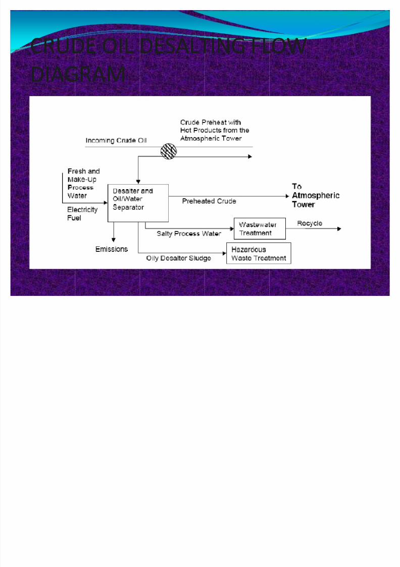
CRUDE OIL DESALTING FLOW
DIAGRAM
12
8/8/2019 Refining Technology Presentation
http://slidepdf.com/reader/full/refining-technology-presentation 13/41
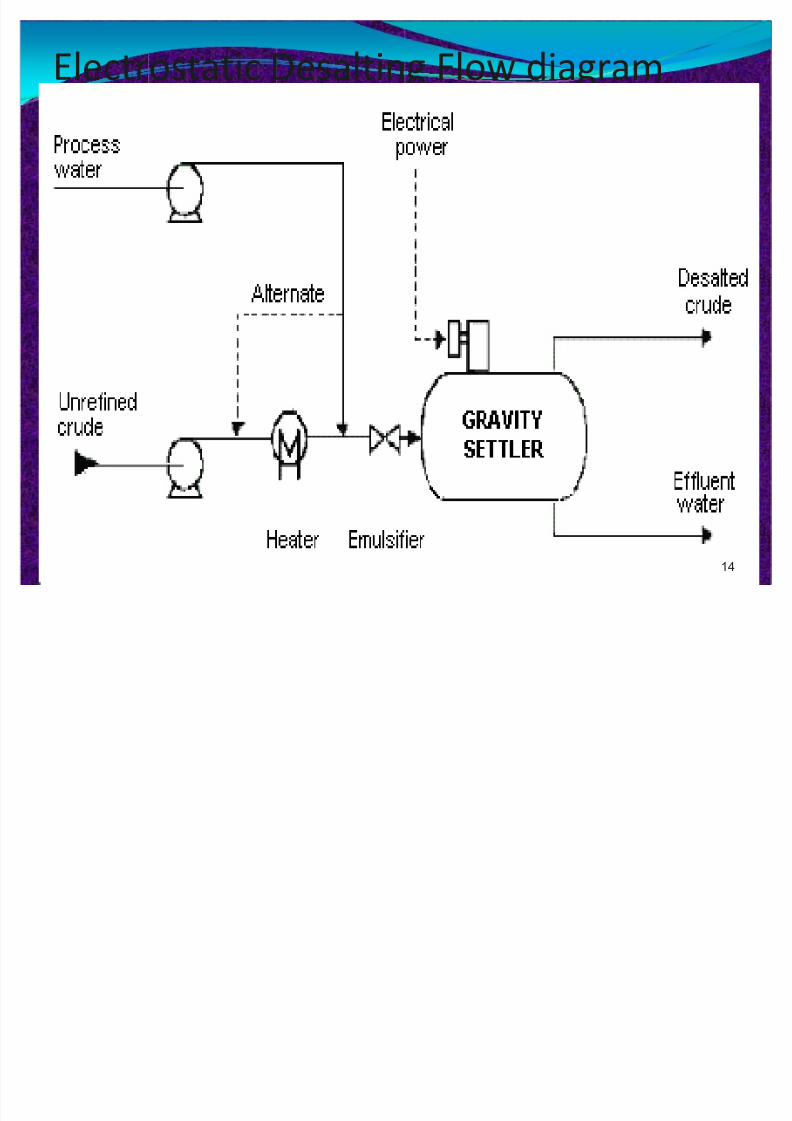
CRUDE OIL DESALTINGy Crude oil often contains water, inorganic salts, suspended
solids, and water-soluble trace metals.
y The two most typical methods of crude-oil desalting,chemical and electrostatic separation, use hot water as the
extraction agent.y In chemical desalting, water and chemical surfactant
(demulsifiers) are added to the crude, heated so that saltsand other impurities dissolve into the water or attach to the
water, and then held in a tank where they settle out.y Electrical desalting is the application of high-voltage
electrostatic charges to concentrate suspended waterglobules in the bottom of the settling tank.
13
8/8/2019 Refining Technology Presentation
http://slidepdf.com/reader/full/refining-technology-presentation 14/41
Electrostatic Desalting Flow diagram
14

8/8/2019 Refining Technology Presentation
http://slidepdf.com/reader/full/refining-technology-presentation 15/41
Desalting Process
Feedstock From Process Typical products-to-Unit
Crude oil Storage treating Desalted crude to Atmosphericdistillation tower Waste water toTreatment
15

8/8/2019 Refining Technology Presentation
http://slidepdf.com/reader/full/refining-technology-presentation 16/41
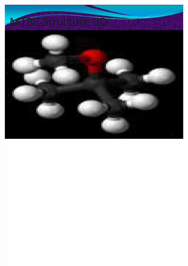
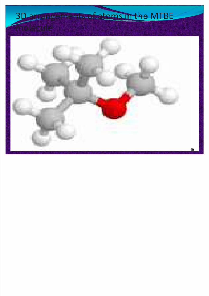
4.Fuel products-MTBEy Methyl tert-butyl ether, also known as methyl
tertiary butyl ether and MTBE, is a chemical
compound with molecular formulaC
5H12O.y MTBE is a volatile, f lammable and colorless liquid that
is immiscible with water.
y MTBE has a minty odor vaguely reminiscent of diethyl
ether, leading to unpleasant taste and odor in water.y MTBE is a gasoline additive, used as an oxygenate and
to raise the octane number.
16
8/8/2019 Refining Technology Presentation
http://slidepdf.com/reader/full/refining-technology-presentation 17/41
MTBE-Structure-3D
17

8/8/2019 Refining Technology Presentation
http://slidepdf.com/reader/full/refining-technology-presentation 18/41
MTBE-Chemical structural formula
18
8/8/2019 Refining Technology Presentation
http://slidepdf.com/reader/full/refining-technology-presentation 19/41
3D arrangements of atoms in the MTBE
molecule
19
8/8/2019 Refining Technology Presentation
http://slidepdf.com/reader/full/refining-technology-presentation 20/41
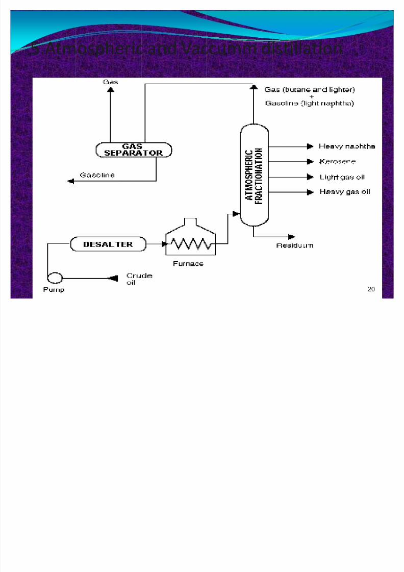
5.Atmospheric and Vaccumm distillation
20
8/8/2019 Refining Technology Presentation
http://slidepdf.com/reader/full/refining-technology-presentation 21/41
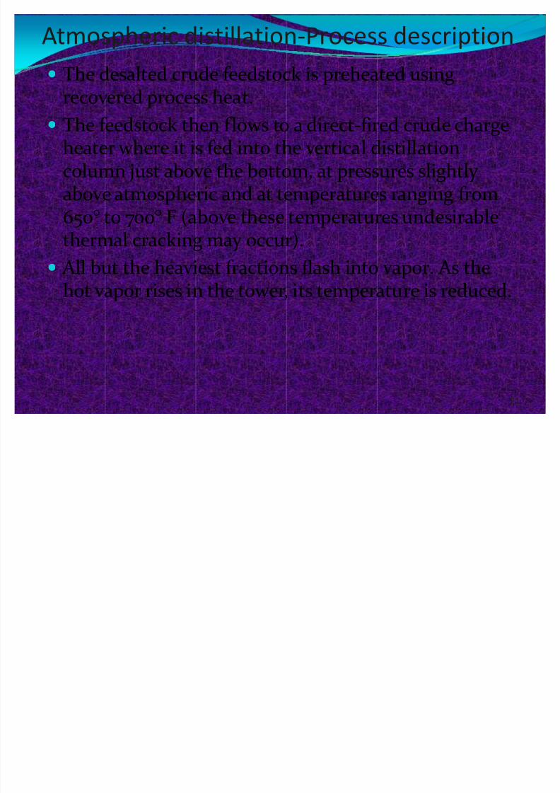
Atmospheric distillation-Process description
y The desalted crude feedstock is preheated using
recovered process heat.y The feedstock then flows to a direct-fired crude charge
heater where it is fed into the vertical distillationcolumn just above the bottom, at pressures slightly
above atmospheric and at temperatures ranging from650° to 700° F (above these temperatures undesirablethermal cracking may occur).
y All but the heaviest fractions flash into vapor. As the
hot vapor rises in the tower, its temperature is reduced.
21
8/8/2019 Refining Technology Presentation
http://slidepdf.com/reader/full/refining-technology-presentation 22/41
Atmospheric distillationy Heavy fuel oil or asphalt residue is taken from the
bottom. At successively higher points on the tower, the
various major products including lubricating oil,heating oil, kerosene, gasoline, and uncondensedgases (which condense at lower temperatures) aredrawn off.
22
8/8/2019 Refining Technology Presentation
http://slidepdf.com/reader/full/refining-technology-presentation 23/41
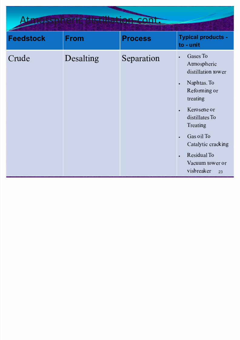
Atmosspheric distillation-cont.
Feedstock From Process Typical products -
to - unit
Cr e esalti e arati y Gases
t s eric
istillati t er
y
a tas.ef r i r
treati
y Ker se e r
istillates
reati
y Gas il
Catal tic crac i
y esi al
ac t er r
is rea er 23
8/8/2019 Refining Technology Presentation
http://slidepdf.com/reader/full/refining-technology-presentation 24/41
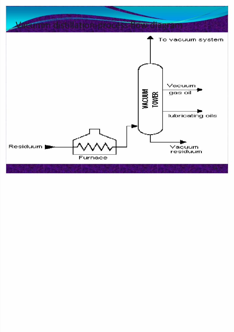
Vacumm distillation-process flow diagram
24
8/8/2019 Refining Technology Presentation
http://slidepdf.com/reader/full/refining-technology-presentation 25/41
Vacuum distillation process
y The process takes place in one or more vacuum distillationtowers.
y The principles of vacuum distillation resemble those of fractional distillation except that larger diameter columns areused to maintain comparable vapor velocities at the reducedpressures.
y A typical first-phase vacuum tower may produce gas oils,lubricating-oil base stocks, and heavy residual for propanedeasphalting.
y . second-phase tower operating at lower vacuum may distillsurplus residuum from the atmospheric tower, which is notused for lube-stock processing, and surplus residuum fromthe first vacuum tower not used for deasphalting.
25
8/8/2019 Refining Technology Presentation
http://slidepdf.com/reader/full/refining-technology-presentation 26/41
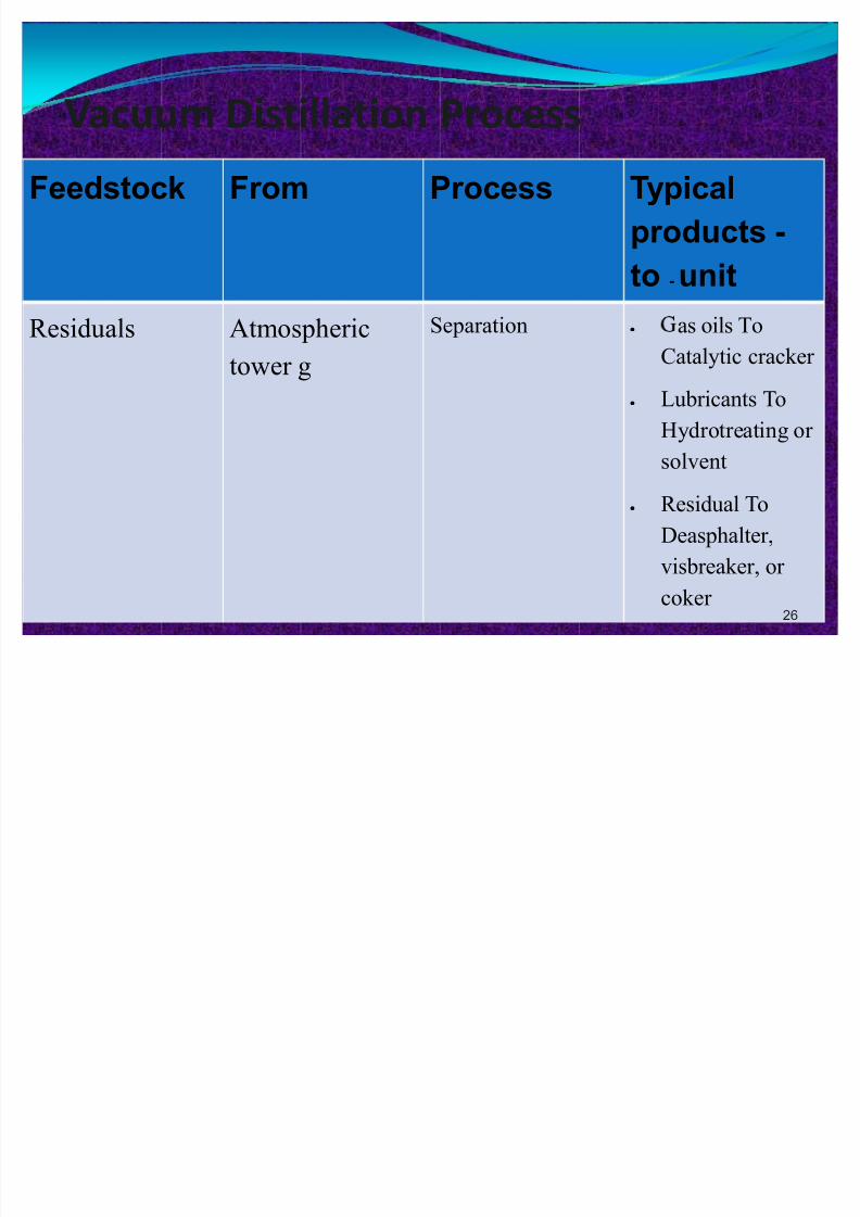
Vacuum Distillation Process
Feedstock From Process Typical
products -
to - unit
Residuals Atmospheric
tower g
Separation y as oils To
Catalytic cracker
y Lubricants To
Hydrotreating or
solvent
y Residual To
Deasphalter,
visbreaker, or
coker 26

8/8/2019 Refining Technology Presentation
http://slidepdf.com/reader/full/refining-technology-presentation 27/41
FLUID CATALYTIC CRACKING
FLOW DIAGRAM
27
8/8/2019 Refining Technology Presentation
http://slidepdf.com/reader/full/refining-technology-presentation 28/41
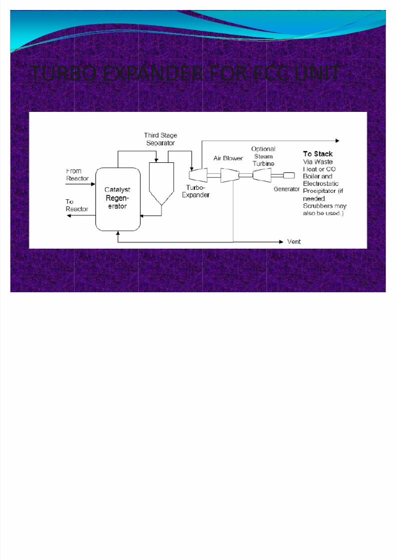
TURBO EXPANDER FOR FCC UNIT
28
8/8/2019 Refining Technology Presentation
http://slidepdf.com/reader/full/refining-technology-presentation 29/41
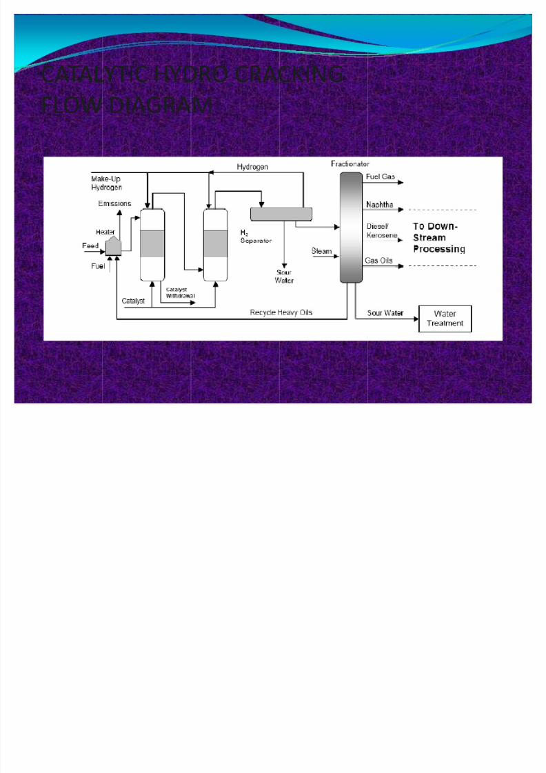
CATALYTIC HYDRO CRACKING
FLOW DIAGRAM
29
8/8/2019 Refining Technology Presentation
http://slidepdf.com/reader/full/refining-technology-presentation 30/41
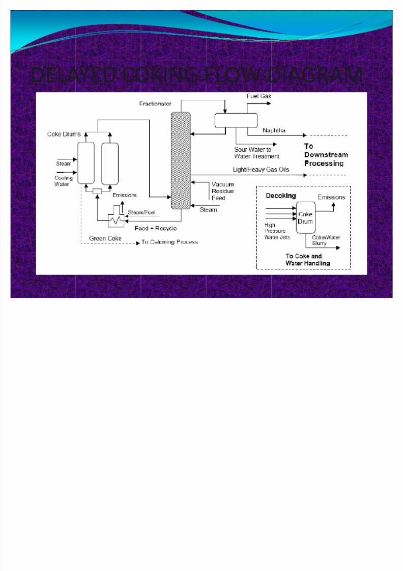
DELAYED COKING FLOW DIAGRAM
30
8/8/2019 Refining Technology Presentation
http://slidepdf.com/reader/full/refining-technology-presentation 31/41
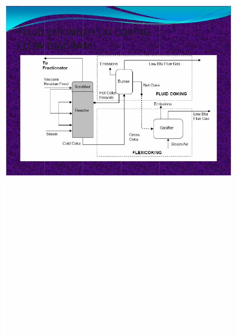
FLUID COKING/FLEXI COKING
FLOW DIAGRAM
31
8/8/2019 Refining Technology Presentation
http://slidepdf.com/reader/full/refining-technology-presentation 32/41
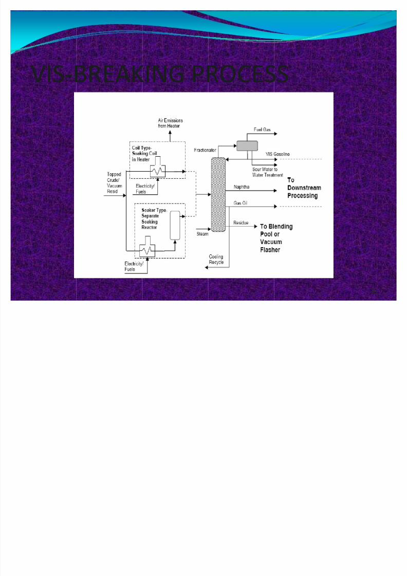
VIS-BREAKING PROCESS
32
8/8/2019 Refining Technology Presentation
http://slidepdf.com/reader/full/refining-technology-presentation 33/41
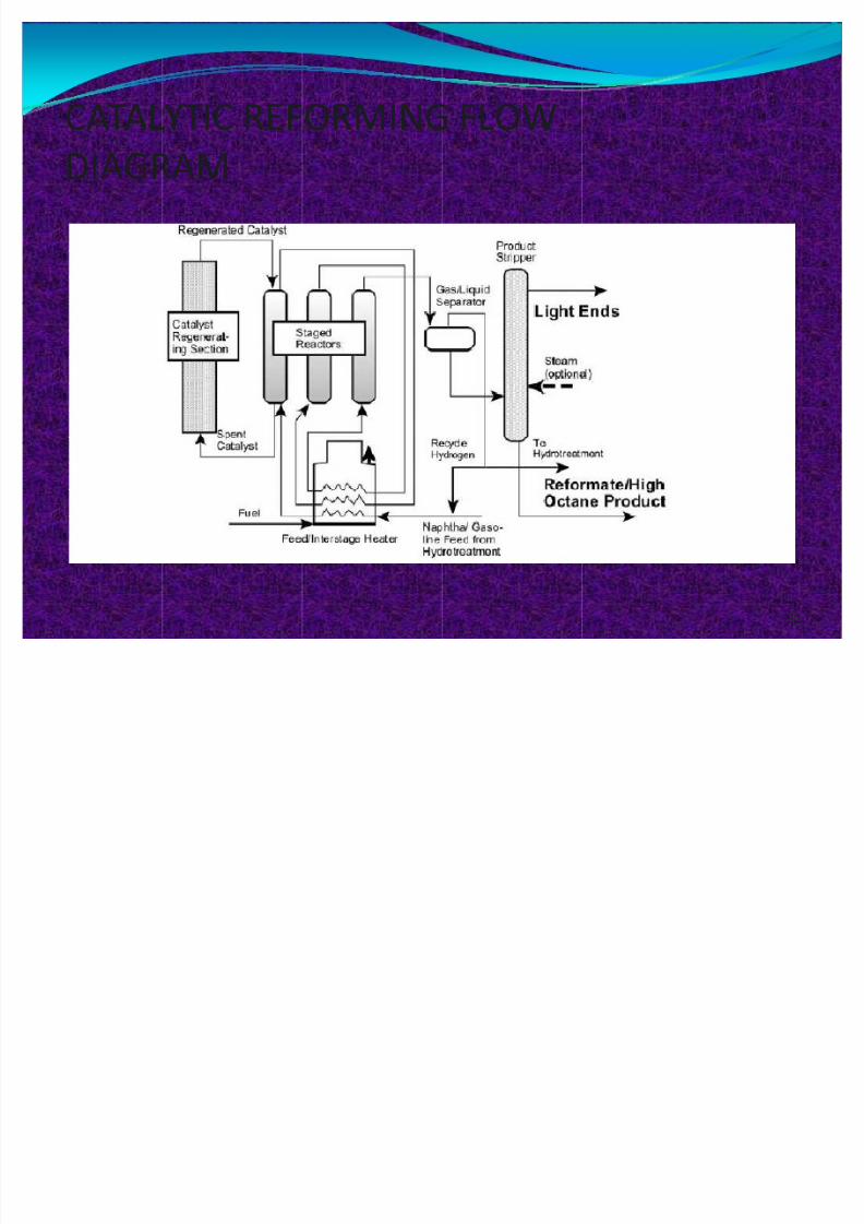
CATALYTIC REFORMING FLOW
DIAGRAM
33

8/8/2019 Refining Technology Presentation
http://slidepdf.com/reader/full/refining-technology-presentation 34/41
DELAYED COKING HARDWARE UNIT
34
8/8/2019 Refining Technology Presentation
http://slidepdf.com/reader/full/refining-technology-presentation 35/41
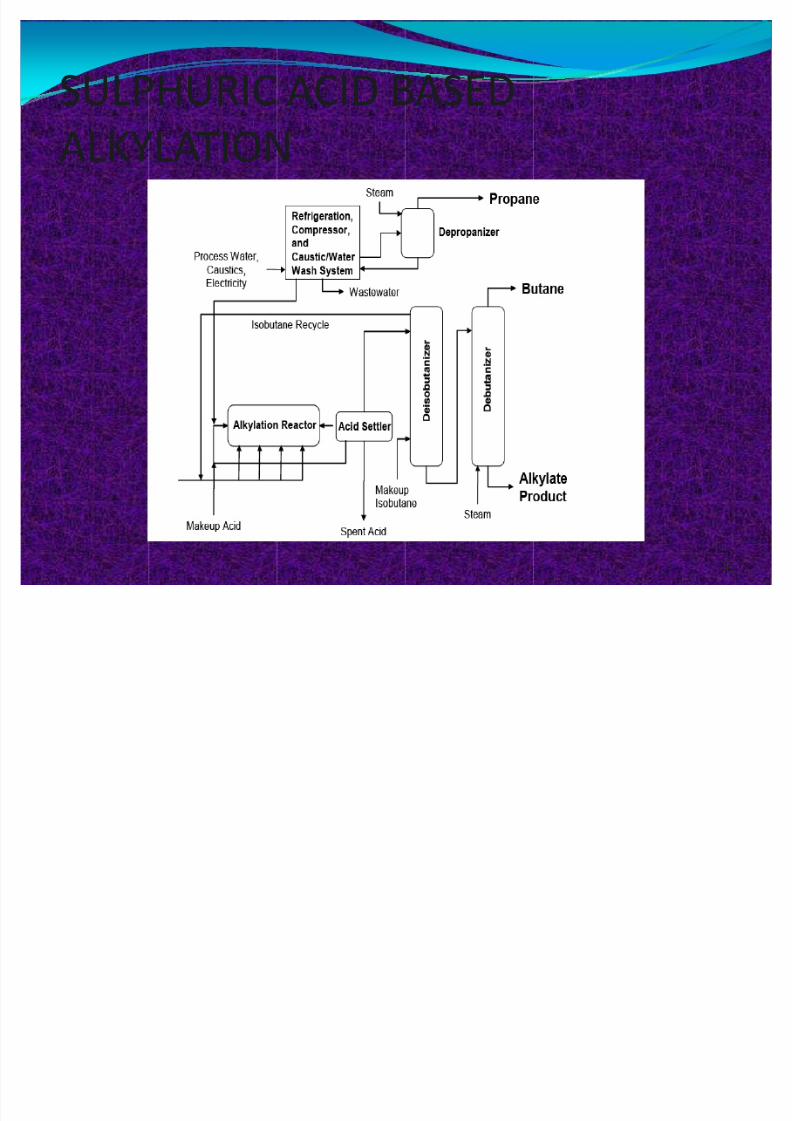
SULPHURIC ACID BASED
ALKYLATION
35
8/8/2019 Refining Technology Presentation
http://slidepdf.com/reader/full/refining-technology-presentation 36/41
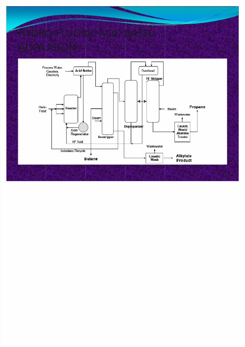
HYDRO-FLUORIC ACID BASED
ALKYLATION
36
8/8/2019 Refining Technology Presentation
http://slidepdf.com/reader/full/refining-technology-presentation 37/41
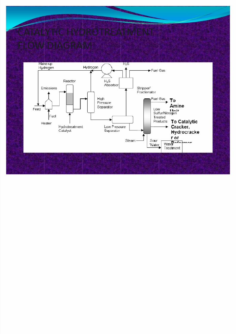
CATALYTIC HYDROTREATMENT
FLOW DIAGRAM
37
8/8/2019 Refining Technology Presentation
http://slidepdf.com/reader/full/refining-technology-presentation 38/41
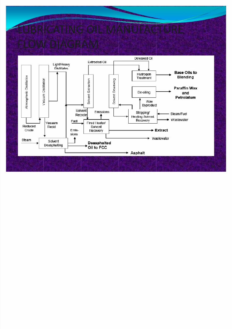
LUBRICATING OIL MANUFACTURE
FLOW DIAGRAM
38

8/8/2019 Refining Technology Presentation
http://slidepdf.com/reader/full/refining-technology-presentation 39/41
SULFUR MANAGEMENT IN
REFINERY
39
8/8/2019 Refining Technology Presentation
http://slidepdf.com/reader/full/refining-technology-presentation 40/41
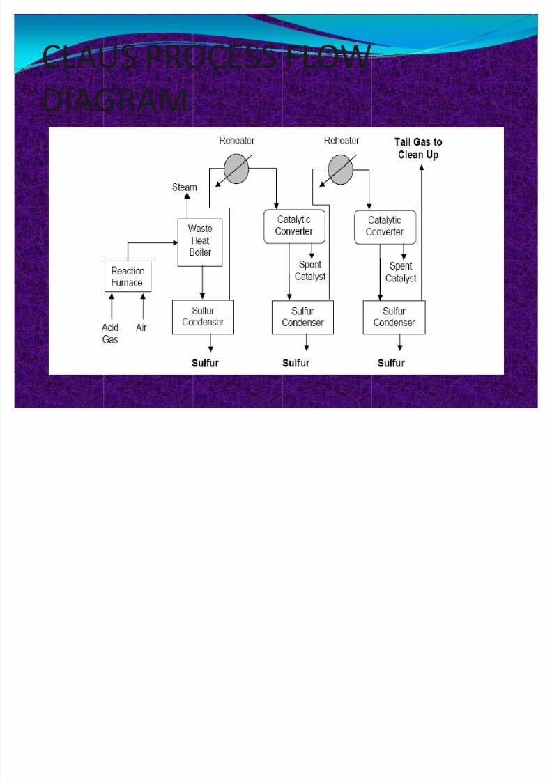
CLAUS PROCESS FLOW
DIAGRAM
40
8/8/2019 Refining Technology Presentation
http://slidepdf.com/reader/full/refining-technology-presentation 41/41
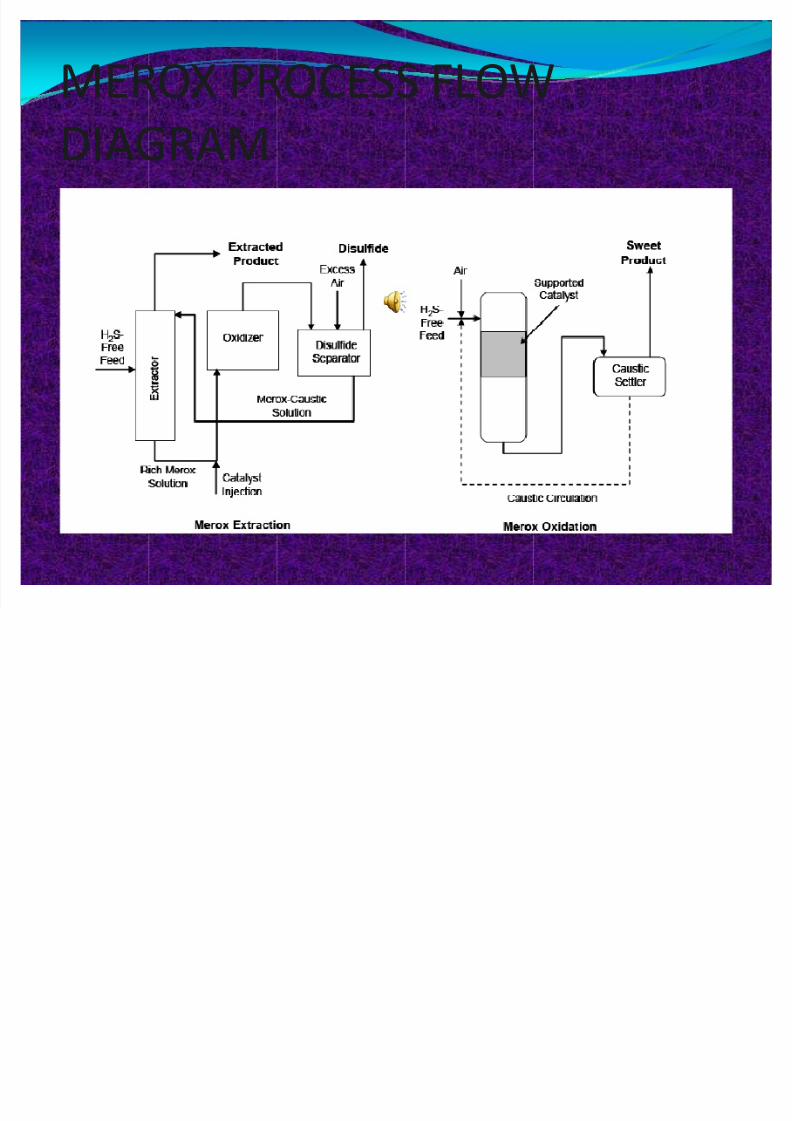
MEROX PROCESS FLOW
DIAGRAM
41