reedjet 100cc -tag
TRANSCRIPT

MAN-86 - USA
overhaul MANUAL
REEDJET 100cc -TaG

MAN-86 - USA
INDEX
ENGINE DISASSEMBLY 1
CRANKSHAFT DISASSEMBLY/ ASSEMBLY 7
CRANKSHAFT DISASSEMBLY OPERATIONS 7
CRANKSHAFT ASSEMBLY OPERATIONS 8
ENGINE ASSEMBLY 10
ATTACHMENTS
- FASTENER TORQUE VALUE 20
- CROSS PATTERN LOCKING ORDER ON CRANKCASE 20
- MAIN PRESCRIPTIONS 21
- WEAR STATUS EVALUATION TABLE FOR BEARING AND
CRANKSHAFT
22
- LITTLE/BIG END CONROD BEARING CLEARANCE
- OVERHAUL TOOLS LIST
- FIXING TOOL ON BENCH VISE
- DRAWING S725/1
- WIRING DIAGRAM
23
24
25
26
27
MAN-86 - USA
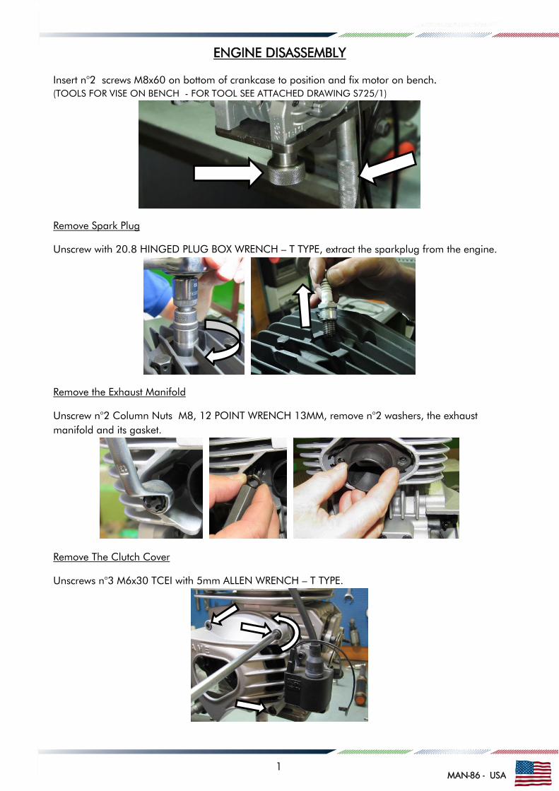
ENGINE DISASSEMBLY
Insert n°2 screws M8x60 on bottom of crankcase to position and fix motor on bench.
(TOOLS FOR VISE ON BENCH - FOR TOOL SEE ATTACHED DRAWING S725/1)
Remove Spark Plug
Unscrew with 20.8 HINGED PLUG BOX WRENCH – T TYPE, extract the sparkplug from the engine.
Remove the Exhaust Manifold
Unscrew n°2 Column Nuts M8, 12 POINT WRENCH 13MM, remove n°2 washers, the exhaust
manifold and its gasket.
Remove The Clutch Cover
Unscrews n°3 M6x30 TCEI with 5mm ALLEN WRENCH – T TYPE.
1

MAN-86 - USA
Remove The Clutch
Unscrew the Bendix cover with 5mm ALLEN WRENCH – T TYPE and remove it.
Insert the ATT.037 – STARTER WHEEL LOOKING TOOL for blocking the crankshaft rotation.
Remove the retain M10 Nut with RING WRENCH 17mm and remove subsequently the external
washer, the complete drum with the roller cage, the internal washer.
With the starter wheel locking tool and ALLEN WRENCH 27mm, remove the M20x1 clutch hub nut.
WARNING: USCREW CLOCKWISE AS THE NUT HAS LEFT-HAND THREAD.
2

MAN-86 - USA
Remove the clutch hub and the starter wheel from the crankshaft through ATT.026 CLUTCH PULLER
and extract the Bendix.
Remove the starter wheel, unscrew n°3 M6 TCEI with ALLEN WRENCH 5mm – T TYPE
Remove The Ignition
If you have to disassemble only the ignition, is possible remove only the Bendix cover on the clutch
side as in photo. The important is that the ATT.037 STARTER WHEEL LOCKING TOOL is on the
place of the crankcase.
Remove the ignition retain Nut M10 with the Ring Wrench 17mm. Remove the Rotor.
3

MAN-86 - USA
Remove the Stator, unscrew n° 2 TCEI M5x25 and remove its washers. Remove ATT.037
Remove the Carburettor Manifold, Outer Reed Pack Gasket, Reed Pack and Inner Reed Pack Gasket.
Remove the Carburettor gasket, unscrews n°4 TCEI M6x25 with ALLEN WRENCH 5mm T TYPE.
Remove the other component of inlet system as in picture.
Remove the Cylinder Head
Unscrew Head Nuts, n°2 Nuts M8 and n°2 Column nuts with SOCKET WRENCH 13MM T-TYPE
4

MAN-86 - USA
Remove Cylinder O-Ring Ø60mm , remove de Spring Cable, remove Cylinder and its gasket.
Remove the Circlips from Piston
Use a Screwdriver with rounded edges.
ATTENTION: DO NOT SCRATCH PISTON OR CIRCLIP SEATS.
Remove Piston Pin, Piston and Cage
Using the PISTON PIN PUNCH - P.N.10200
5

MAN-86 - USA
Remove Starter Group
Untighten the screws that fix the starter support to the engine. Unscrew also the other screws that
fixing the Bendix support to the engine.
Opening The Crankcase
Remove 7 fixing Screws (n°5 M6x45 n°3 M6x60), unscrew with ALLEN WRENCH 5mm.
Open the crankcase using a PLASTIC MALLET.
Remove Oil Seals / Bearing if necessary
Use a SCREWDRIVER for Seals. For the bearing, heat half crankcase at 70° or use press and
special pusher as in picture S725/1.
N.B. Remove and preserve Shims
6

MAN-86 - USA
CRANKSHAFT DISASSEMBLY / ASSEMBLY
ATTENTION:
THE DISASSEMBLY/ASSEMBLY OPERATIONS ON THE CRANKSHAFT, MUST BE PERFORMED ONLY
BY AN AUTHORIZED SERVICE CENTER USING THE SPECIALLY DESIGNED TOOLS.
USE OF UNFITTED TOOLS OR PERFORMED OPERATIONS BY UNSKILLED PERSONNEL MAY
DAMAGE THE CRANKSHAFT BEYOND REPAIR.
TOOLS DESCRIPTION N° PART
CRANKSHAFT ASSEMBLY KIT 10110A
CRANKPIN BUSH ( INCLUDED IN 10110A) 10150A
CRANKSHAFT DISASSEMBLY KIT INCLUDES 10100-C2
- CRANKSHAFT SUPPORT/ DISASSEMBLY TOOL 10100
- CRANKSHAFT PLATE / DISASSEMBLY TOOL 10104A
- CRANKSHAFT INSERT 10106
- CRANKPIN PUSHER 10107
CRANKSHAFT DISASSEMBLY OPERATIONS
Place the disassembly tool under the press (5 MeT PRESS and disassembly KIT P.N. 10100).
Place the crankshaft plate (P.N. 10104A) between the crankshaft halves. After insert the crankshaft
insert (P.N. 10106) and using the crankpin pusher (P.N. 10107) press the crankpin out.
Disassemble the complete conrod with washers. Repeat the operations to extract the crankpin from
the other half crankshaft.
BEFORE REASSEMBLING, WASH ALL PARTS WITH KEROSENE
IMPORTANT: IF THE DISASSEMBLED PARTS AREN’T BRAND NEW AND WILL BE REASSEMBLED WITHOUT
SUBSTITUTION, THEY MUST BE PLACED IN THE SAME SENSE / POSITION AS BEFORE.
WE SUGGEST TO MARK CONROD AND WASHES BEFORE DISASSEMBLE, AND PARTICULAR ATTENTION
HAS TO BE PAID TO THE ROLLER CAGE, WHOSE ROLLERS CAN FALL IF CRANKPIN OR SOMETHING
SIMILAR IS NOT PRESENT INSIDE CAGE ITSELF.
FOLLOW ATTACHED TABLE FOR MAX. CLEARANCE FOR CON-ROD, CRANKPIN, CAGE.
a) CHECK STATUS OF CONROD-TOP AND BOTTOM. IF OVALIZATION EXCEEDS 0.01mm. REPLACE CONROD.
-0.01 centesimal micrometre (21/50) -0.001 bore gauge with check ring ø 24 and ø18 diam.
b) CHECK STATUS OF ROLLER CAGE (BIG END) VISUAL CHECK – REPLACE IF NECESSARY BUT ALWAYS AFTER 30 HEURES OF WORKING REPLACING CAGE WITH PIN AND WASHERS.
c) CHECK STATUS OF CRANKSHAFT HALVES. REPLACE IF BEARING SEAT DIAMETER IS BELOW 0.030mm VS. NEW.
d) CHECK STATUS OF SILVER WASHERS VISUAL CHECK – REPLACE IF NECESSARY.
7

MAN-86 - USA
CRANKSHAFT ASSEMBLY OPERATIONS
Place the crankshaft assembly tool P.N. 10110A under the press (5MeT Press), vertically.
Place the half crankshaft into the assembly tool. Oil Crankpin and crankpin hole on
crankshaft.
Place crankpin with crankpin bush (P.N. 10150A) on half crankshaft.
BE SURE THAT CRANKPIN IS WELL CENTERED INTO ITS HOLE ON CRANKSHAFT.
Bring upper plate of tool in contact with crankpin.
Progressively press until crankpin is completely driven in. After extract bush from crankpin
and put in horizontal position.
After have lubricated crankpin, insert the silver washer, the conrod with roller cage and the
other silver washer.
ATTENTION:
ROLLERS ARE FREE IN THE CAGE, PREVENT ROLLERS FROM FALLING WHEN INSERTING
ON CRANKPIN
8

MAN-86 - USA
Place second half crankshaft in the seat of the counter plate. Bring the two plates close until
the tool is hand pressed.
BE SURE THAT CRANKPIN IS WELL CENTERED INTO ITS HOLE ON CRANKSHAFT
Oil crankpin and crankpin hole on half crankshaft. Put tool in vertical position. Progressively
press the two crankshaft halves together. Open the tool, put it in horizontal position and
extract the crankshaft.
Check the axial clearance of the conrod, it must be MIN. 0.4mm / MAX. 0.6mm
IF CLEARANCE IS HIGHER OR LOWER, REBUILD THE CRANKSHAFT
AFTER ASSEMBLING, THE CRANKSHAFT MUST BE ALIGNED. OTHERWISE RESULT
EXCESSIVE VIBRATION, HARD STARTING OR POOR ACCELERATION.
Place the crankshaft between the centres with dial gauges indicators reading on left and
right bearing seats. Use the copper hammer to align the crankshaft (if necessary).
Rotate crankshaft and look at deflection of gauge needles. The deflection must be, after
centring, MAX. 0,01mm.
9
MAN-86 - USA
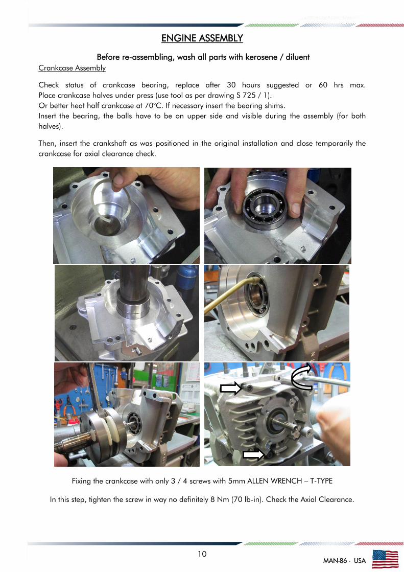
ENGINE ASSEMBLY
Before re-assembling, wash all parts with kerosene / diluent
Crankcase Assembly
Check status of crankcase bearing, replace after 30 hours suggested or 60 hrs max.
Place crankcase halves under press (use tool as per drawing S 725 / 1).
Or better heat half crankcase at 70°C. If necessary insert the bearing shims.
Insert the bearing, the balls have to be on upper side and visible during the assembly (for both
halves).
Then, insert the crankshaft as was positioned in the original installation and close temporarily the
crankcase for axial clearance check.
Fixing the crankcase with only 3 / 4 screws with 5mm ALLEN WRENCH – T-TYPE
In this step, tighten the screw in way no definitely 8 Nm (70 lb-in). Check the Axial Clearance.
10
MAN-86 - USA
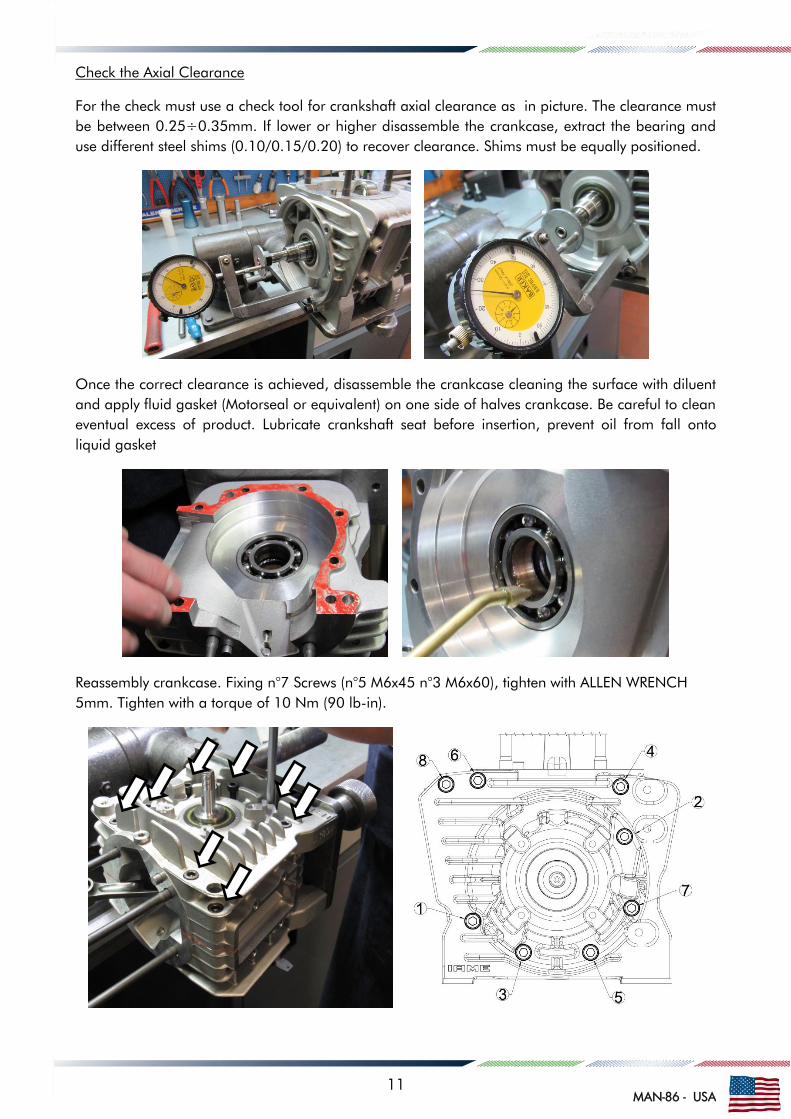
Check the Axial Clearance
For the check must use a check tool for crankshaft axial clearance as in picture. The clearance must
be between 0.25÷0.35mm. If lower or higher disassemble the crankcase, extract the bearing and
use different steel shims (0.10/0.15/0.20) to recover clearance. Shims must be equally positioned.
Once the correct clearance is achieved, disassemble the crankcase cleaning the surface with diluent
and apply fluid gasket (Motorseal or equivalent) on one side of halves crankcase. Be careful to clean
eventual excess of product. Lubricate crankshaft seat before insertion, prevent oil from fall onto
liquid gasket
Reassembly crankcase. Fixing n°7 Screws (n°5 M6x45 n°3 M6x60), tighten with ALLEN WRENCH
5mm. Tighten with a torque of 10 Nm (90 lb-in).
11

MAN-86 - USA
Where is necessary change the oil seal, apply special grease on lips before the insert (mark on seal
to be outside), use special tool as in drawing S 725 / 1.
ATTENTION:
THE OIL SEAL SHOULD BE REPLACED AFTER MAX 10 HEURES AND ALWAYS WHEN DISASSEMBLED
Install Piston
Check status of roller cage, the cage must be replaced after use of 160 litres or 20 hours.
Check status of piston pin, must be replaced every replacing piston or 10÷20 hours.
SEE ATTACHMENT ON MATCHING SELECTIONS
ATTENTION
CHECK FIRST THE PISTON RING END GAP USING A THICKNESS GAUGE. MEASURE THE END
GAP OF THE PISTON RING WHEN INSERTED IN THE CYLINDER GAP SHOULD BE 0.15÷0.40
REPLACED THE PISTON RING IF THE END GAP EXCEEDS 0.50mm
After install ring on the piston
ATTENTION
CLEARANCE BETWEEN PISTON AND LINER MUST BE 0.090÷0.095mm, IF CLEARANCE IS HIGHER
THAN 0.14mm THE PISTON MUST BE REPLACED (AN INSPECTION MUST BE CARRIED OUT AFTER
ABOUT A USE OF 45 LITERS OR 5 HOURS OF USE, AND THE PISTONS ARE MEASURED AT
17.5mm FROM BOTTOM.
ALWAYS REPLACE PISTON COMPLETE WITH THE RING.
12

MAN-86 - USA
Match piston, pin, cage is the same as shown on the attachment, insert pin and cage on the piston.
Lubricate any components. Make sure that the arrow on top of the piston is towards the exhaust. As
general rule, the pin must be inserted in the hole with a little forced coupling. If coupling is slack,
replaced it with a higher diameter pin. Using piston pin punch as guide.
Position Circlip On Tool
Grease tool to keep circlip in place, use TOOL P.N. 10120, insert circlips and check that both the
circlips are correctly in seat.
Install a New Cylinder Gasket and Cylinder
Lubricate the cylinder and piston, install cylinder.
13

MAN-86 - USA
Check status of cylinder head, clean from deposits, do not scratch combustion chamber.
After the check, install O-Ring and cylinder head. Install n°4 head washer, then tighten n°2 Nuts M8
and n°2 Column nuts M8 with SOCKET WRENCH 13mm T-TYPE (18÷22Nm – 160÷190lb-in).
Re-Assembly of The Clutch
Before assembling the clutch, wash with the diluent: the shaft cone, the starter wheel and the clutch
drum.
Assemble the starter wheel on the clutch hub, tighten n°3 M6 TCEI with ALLEN WRENCH 5mm – T
TYPE (10÷12 Nm – 90÷110 lb-in) and the dragging pin. Apply “Loctite” thread locker on screws.
ATTENTION:
IT’S NECESSARY TO ALWAYS INSTALL Ø7mm PIN, EVENTUAL KICKS COULD SHEAR THE SCREWS
Apply “Loctite 641” for coaxial locking. Place the clutch hub and the starter wheel on the shaft.
Insert on the crankshaft and position the ATT.037 STARTER WHEEL LOCKING TOOL.
14

MAN-86 - USA
Apply the “Loctite” thread locker. Assemble fixing nut, clutch hub and starter wheel, thought the
STARTER WHEEL LOCKING TOOL and ALLEN WRENCH 27mm (torque 100÷110 Nm – 900÷990).
WARNING: SCREW COUNTER CLOCKWISE AS THE NUT HAS LEFT-HAND THREAD.
Assemble the internal washer (the bevel of the washer hole must be towards the shaft). Install the
O-Ring. Clean the roller cage and grease it before assembling it on the shaft.
Mount the clutch drum and external washer (the bevel of the washer hole must be towards the shaft).
With the ATT.037 STARTER WHEEL LOCKING TOOL, tighten the drum retain nut (nut M10).
Use RING WRENCH 17mm (torque at 30÷40 Nm – 270÷360 lb-in).
15

MAN-86 - USA
Installation Bendix Support
Fixing n°4 Screw M6x45 use 5mm ALLEN WRENCH – T TYPE (torque at 8÷10 Nm – 70÷90 lb-in).
Grease the Bendix cage, after insert the Bendix and fixing the cover, n°3 M6x25 with 5mm ALLEN
WRENCH – T TYPE (torque at 6÷8 Nm – 55÷70 lb-in).
Installation of the Starter Support
Place the support on the crankcase and tighten the n°3 M6x25 and n°1 M6x30, use 5mm ALLEN
WRENCH – T TYPE (torque at 8÷10 Nm – 70÷90 lb-in).
16

MAN-86 - USA
Re-Assembly The Ignition
Install ignition rotor on shaft, the spacer-washer , the knurled washer and the nut M10. Remove the
Bendix cover if was installed. Tighten all with a 12 POINT WRENCH 17mm and ATT.037 STARTER
WHEEL LOCKING TOOL in position.
After remove ATT.037 STARTER WHEEL LOCKING TOOL, and install the Bendix cover.
Tighten n°3 M6x25 with 5mm ALLEN WRENCH – T TYPE (torque at 6÷8 Nm – 55÷70 lb-in).
Install the stator ignition on the crankcase, position the washer and tighten but not in way definitely
n°2 M5x25 screws and. Use 4mm ALLEN WRENCH – T TYPE.
17
MAN-86 - USA
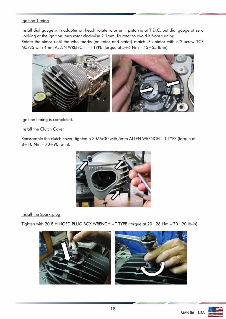
Ignition Timing
Install dial gauge with adapter on head, rotate rotor until piston is at T.D.C. put dial gauge at zero.
Looking at the ignition, turn rotor clockwise 2.1mm, fix rotor to avoid it from turning.
Rotate the stator until the who marks (on rotor and stator) match. Fix stator with n°2 screw TCEI
M5x25 with 4mm ALLEN WRENCH – T TYPE (torque at 5÷6 Nm – 45÷55 lb-in).
Ignition timing is completed.
Install the Clutch Cover
Reassemble the clutch cover, tighten n°3 M6x30 with 5mm ALLEN WRENCH – T TYPE (torque at
8÷10 Nm – 70÷90 lb-in).
Install the Spark-plug
Tighten with 20.8 HINGED PLUG BOX WRENCH – T TYPE (torque at 20÷26 Nm – 70÷90 lb-in).
18
MAN-86 - USA
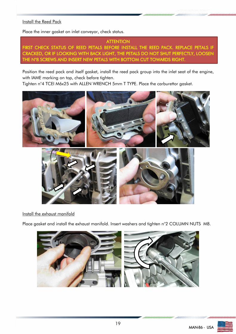
Install the Reed Pack
Place the inner gasket on inlet conveyor, check status.
ATTENTION
FIRST CHECK STATUS OF REED PETALS BEFORE INSTALL THE REED PACK. REPLACE PETALS IF
CRACKED, OR IF LOOKING WITH BACK LIGHT, THE PETALS DO NOT SHUT PERFECTLY, LOOSEN
THE N°8 SCREWS AND INSERT NEW PETALS WITH BOTTOM CUT TOWARDS RIGHT.
Position the reed pack and itself gasket, install the reed pack group into the inlet seat of the engine,
with IAME marking on top, check before tighten.
Tighten n°4 TCEI M6x25 with ALLEN WRENCH 5mm T TYPE. Place the carburettor gasket.
Install the exhaust manifold
Place gasket and install the exhaust manifold. Insert washers and tighten n°2 COLUMN NUTS M8.
19
MAN-86 - USA
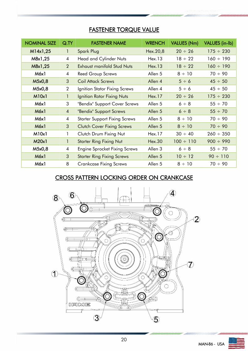
FASTENER TORQUE VALUE
CROSS PATTERN LOCKING ORDER ON CRANKCASE
NOMINAL SIZE Q.TY FASTENER NAME WRENCH VALUES (Nm) VALUES (in-lb)
M14x1,25 1 Spark Plug Hex.20,8 20 ÷ 26 175 ÷ 230
M8x1,25 4 Head and Cylinder Nuts Hex.13 18 ÷ 22 160 ÷ 190
M8x1,25 2 Exhaust manifold Stud Nuts Hex.13 18 ÷ 22 160 ÷ 190
M6x1 4 Reed Group Screws Allen 5 8 ÷ 10 70 ÷ 90
M5x0,8 3 Coil Attack Screws Allen 4 5 ÷ 6 45 ÷ 50
M5x0,8 2 Ignition Stator Fixing Screws Allen 4 5 ÷ 6 45 ÷ 50
M10x1 1 Ignition Rotor Fixing Nuts Hex.17 20 ÷ 26 175 ÷ 230
M6x1 3 "Bendix" Support Cover Screws Allen 5 6 ÷ 8 55 ÷ 70
M6x1 4 "Bendix" Support Screws Allen 5 6 ÷ 8 55 ÷ 70
M6x1 4 Starter Support Fixing Screws Allen 5 8 ÷ 10 70 ÷ 90
M6x1 3 Clutch Cover Fixing Screws Allen 5 8 ÷ 10 70 ÷ 90
M10x1 1 Clutch Drum Fixing Nut Hex.17 30 ÷ 40 260 ÷ 350
M20x1 1 Starter Ring Fixing Nut Hex.30 100 ÷ 110 900 ÷ 990
M5x0,8 4 Engine Sprocket Fixing Screws Allen 3 6 ÷ 8 55 ÷ 70
M6x1 3 Starter Ring Fixing Screws Allen 5 10 ÷ 12 90 ÷ 110
M6x1 8 Crankcase Fixing Screws Allen 5 8 ÷ 10 70 ÷ 90
20

MAN-86 - USA
MAIN PRESCRIPTIONS
ENGINE CRANKSHAFT MATCHING THE PISTON
Bearing seat diameter on new engine
Refer to the attached table to define the state of wear
of the drive shafts.
Replace when size is lower than 0.03mm vs. original.
The replacement operation must be carried out
after about a use of 60 hours.
ATTENTION:
Clearance between piston and liner must be:
0.090 / 0.095mm.
If clearance is higher than 0.14mm, must be
replaced the piston.
MAX ALLOWED OVALIZATION ON
CONROD
Max. allowed ovalization between A and B on new
conrod: 0.002mm
Max. allowed ovalization between A and B on used
conrod: 0.01mm
An inspection must be carried out after about
30 hours use. When ovalization reaches 0,01mm
(the difference between the measured diameter in the
positions shown below “A” and “B”) the conrod must
be replaced.
The replacement operation must be carried out about
a use of 60 hours.
An inspection must be carried out after about a
use of 45 litres or 5 hours of use, and the pistons are
measured at 17.5mm from bottom.
The replacement operation must be carried out about
a use of 10 hours or 80 litres.
Size of the liner to be matched with piston is
marked on top of piston.
Allowed ring gap 0.15÷0.40 mm.
ESTIMATED AVERAGE LIFE OTHER
COMPONENTS
Big End Conrod Roller
Bearing + Crankpin
+ silver washers
= 30 hours
Little End Conrod
Roller Bearing + Piston
Pin
= 10 to 20 hours
21
MAN-86 - USA
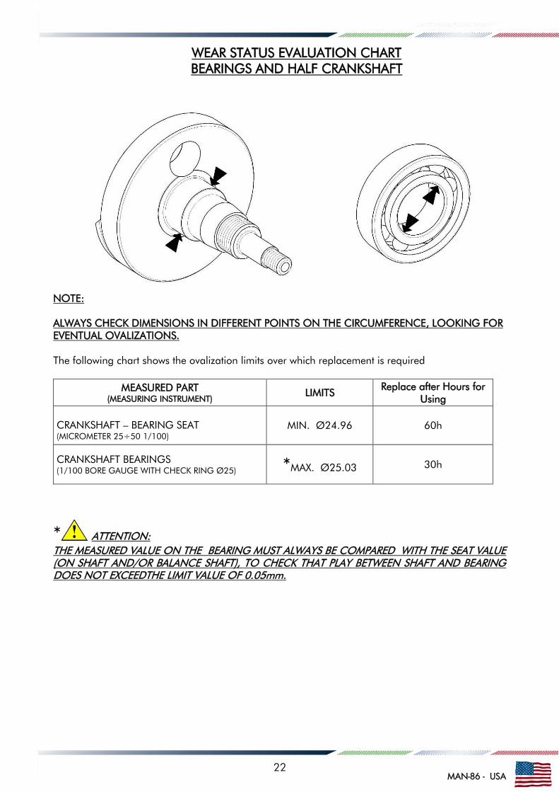
WEAR STATUS EVALUATION CHART
BEARINGS AND HALF CRANKSHAFT
NOTE:
ALWAYS CHECK DIMENSIONS IN DIFFERENT POINTS ON THE CIRCUMFERENCE, LOOKING FOR
EVENTUAL OVALIZATIONS.
The following chart shows the ovalization limits over which replacement is required
MEASURED PART
(MEASURING INSTRUMENT)
LIMITS Replace after Hours for
Using
CRANKSHAFT – BEARING SEAT
(MICROMETER 25÷50 1/100)
MIN. Ø24.96 60h
CRANKSHAFT BEARINGS
(1/100 BORE GAUGE WITH CHECK RING Ø25) *MAX. Ø25.03
30h
* ATTENTION:
THE MEASURED VALUE ON THE BEARING MUST ALWAYS BE COMPARED WITH THE SEAT VALUE
(ON SHAFT AND/OR BALANCE SHAFT), TO CHECK THAT PLAY BETWEEN SHAFT AND BEARING
DOES NOT EXCEEDTHE LIMIT VALUE OF 0.05mm.
22

MAN-86 - USA
LITTLE / BIG END CONROD BEARINGS CLEARANCE
23

MAN-86 - USA
OVERHAUL TOOL LIST
SPECIFIC TOOLS AVAILABLE AT IAME
DESCRIPTION P.N.
PISTON STROKE LOCKER 10271
SPROCKET PULLER 10612
ROTOR PULLER ATT.026
PISTON PIN PUNCH 10200
PISTON CIRCLIP ASSEMBLY TOOL 10120
CRANKSHAFT ASSEMBLY KIT
it includes:
- crankpin bush
10110-A
10150A
KIT CRANKSHAFT DISASSEMBLY KIT
it includes:
- Crankshaft plate
- Crankshaft support
- Crankpin pusher
- crankshaft insert
10100 – C2
10104A
10100
10107
10106
TIMING CHECK TOOL
VOLUMETER
10192
ATT.063 / 2
SPECIFIC TOOLS – DRAWINGS ONLY – Draw. S725/1
ENGINE FIXING TOOL
BEARING DISASSEMBLY TOOL
BEARING ASSEMBLY TOOL
CIRCLIP ASSEMBLY TOOL
STANDARD TOOLS
ALLEN WRENCH T TYPE 4mm
ALLEN WRENCH T TYPE 5mm
SOCKET WRENCH T TYPE 10mm
SOCKET WRENCH T TYPE 13mm
12 POINT WRENCH
13mm
12 POINT WRENCH 17mm
12 POINT WRENCH 27mm
HINGED PLUG BOX WRENCH – T TYPE 20.8mm
SCREWDRIVER WITH ROUNDED EDGES
PLASTIC MALLET
SOCKET TYPE-DYNAMOMETRIC
5 MeT PRESS
13mm / 10mm
24

MAN-86 - USA
FIXING TOOL ON BENCH VISE
MATERIAL: Steel Fe 50 UNI 5332
25

MAN-86 - USA
Drawing S725/1
26

MAN-86 - USA
WIRING DIAGRAM
1- Sta
rt &
Sto
p button
2- Battery
3- Ig
nitio
n adapte
r
4- Sta
rte
r
5- H
.T. C
oil
6- Ig
nitio
n
27