mx-100cc installation & operations...
TRANSCRIPT
MX-100CC Installation & Operations Manual
Software Revision 1.17.3
West Pond Enterprises, LLC
6/28/2018
Confidential Page 1
Contents Revision History ............................................................................................................................................ 3
Related documentation ................................................................................................................................ 3
Terms and terminology ................................................................................................................................. 3
MX-100CC ..................................................................................................................................................... 3
MX-100CC Hardware................................................................................................................................. 5
MX-100CC Software .................................................................................................................................. 5
Setting up the system ................................................................................................................................... 5
Unpacking the unit .................................................................................................................................... 5
Installing .................................................................................................................................................... 6
Making the connections ............................................................................................................................ 6
Power On .................................................................................................................................................. 6
Configuring the system ................................................................................................................................. 6
Accessing the WebUI ................................................................................................................................ 6
Getting familiar with the MX-100 ................................................................................................................. 8
Overview ................................................................................................................................................... 9
Sources .................................................................................................................................................... 10
Network Sources ................................................................................................................................. 10
Video Server ........................................................................................................................................ 10
Video Wrapper .................................................................................................................................... 11
Outputs ................................................................................................................................................... 14
Modulated RF Output ......................................................................................................................... 15
Program Mapping ............................................................................................................................... 15
Oversubscribing the Transport ........................................................................................................... 16
Display Controls ...................................................................................................................................... 17
Monitor ................................................................................................................................................... 17
System ..................................................................................................................................................... 18
Settings ................................................................................................................................................ 18
Accounts .............................................................................................................................................. 19
Log ....................................................................................................................................................... 19
Info ...................................................................................................................................................... 19
Tools .................................................................................................................................................... 20

Confidential Page 2
Appendix A – Quick Start Help .................................................................................................................... 21
Appendix B – FAQs ...................................................................................................................................... 22
How do I create a TV channel from a video file? ................................................................................ 22
Confidential Page 3
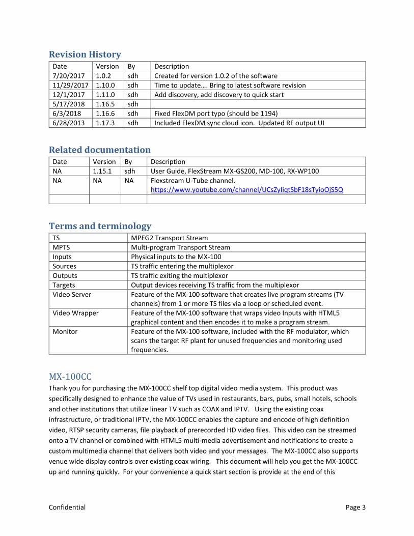
Revision History Date Version By Description
7/20/2017 1.0.2 sdh Created for version 1.0.2 of the software
11/29/2017 1.10.0 sdh Time to update…. Bring to latest software revision
12/1/2017 1.11.0 sdh Add discovery, add discovery to quick start
5/17/2018 1.16.5 sdh
6/3/2018 1.16.6 sdh Fixed FlexDM port typo (should be 1194)
6/28/2013 1.17.3 sdh Included FlexDM sync cloud icon. Updated RF output UI
Related documentation Date Version By Description
NA 1.15.1 sdh User Guide, FlexStream MX-GS200, MD-100, RX-WP100
NA NA NA Flexstream U-Tube channel. https://www.youtube.com/channel/UCsZyIiqtSbF18sTyioOjS5Q
Terms and terminology TS MPEG2 Transport Stream
MPTS Multi-program Transport Stream
Inputs Physical inputs to the MX-100
Sources TS traffic entering the multiplexor
Outputs TS traffic exiting the multiplexor
Targets Output devices receiving TS traffic from the multiplexor
Video Server Feature of the MX-100 software that creates live program streams (TV channels) from 1 or more TS files via a loop or scheduled event.
Video Wrapper Feature of the MX-100 software that wraps video Inputs with HTML5 graphical content and then encodes it to make a program stream.
Monitor Feature of the MX-100 software, included with the RF modulator, which scans the target RF plant for unused frequencies and monitoring used frequencies.
MX-100CC Thank you for purchasing the MX-100CC shelf top digital video media system. This product was
specifically designed to enhance the value of TVs used in restaurants, bars, pubs, small hotels, schools
and other institutions that utilize linear TV such as COAX and IPTV. Using the existing coax
infrastructure, or traditional IPTV, the MX-100CC enables the capture and encode of high definition
video, RTSP security cameras, file playback of prerecorded HD video files. This video can be streamed
onto a TV channel or combined with HTML5 multi-media advertisement and notifications to create a
custom multimedia channel that delivers both video and your messages. The MX-100CC also supports
venue wide display controls over existing coax wiring. This document will help you get the MX-100CC
up and running quickly. For your convenience a quick start section is provide at the end of this

Confidential Page 4
document. See Appendix A – Quick Start Help. For more information please contact West Pond
Enterprises sales or support.
The single system provides features that normally require a collection of rack mounted equipment, set
top boxes, and media servers. Integrating these components together not only reduces the cost and
space required to host the system, it enables advanced features and simplifies overall operation. A
single UI allows you to manage the entire system. Here’s a list of standard equipment the MX-100CC
replaces.
Video Server / Streamer
o Load up to 30 hours of video files onto the MX-100CC and create custom TV channels via
our built in video server. Create a looping playlist or schedule playback at specific times.
Video Encoder - HDMI / Component / Composite
o Capture video and audio from the HD video port and encoded it to broadcast quality
standards. This box supports h.264 and MPEG2 video and a variety of audio formats.
Digital Signage Player
o The HTML5 video wrapper combines video streams with HTML5 media to create a
dynamic multi-media experience on one or more TVs without a digital signage player.
This powerful tool is made simple through presentation templates provided by West
Pond. See http://www.westpond.com/templates for a list of recent templates.
Demux – Remux Multichannel Multiplexer
o Our integrated scalable multiplexer replaces the need for external rack mounted
devices.
Multi-channel modulator
o 1 multi-channel, frequency and modulation agile modulator.
RF Monitor (optional)
o Scanning of broadcast and cable TV channels to discover new channels and
identify/resolve issues is now automated. TV no longer required.
Display controller
o Every display on your linear TV network can now be controlled via the integrated display
control system. Just register the West Pond display control device with the MX-100CC
and set its state.
Confidential Page 5
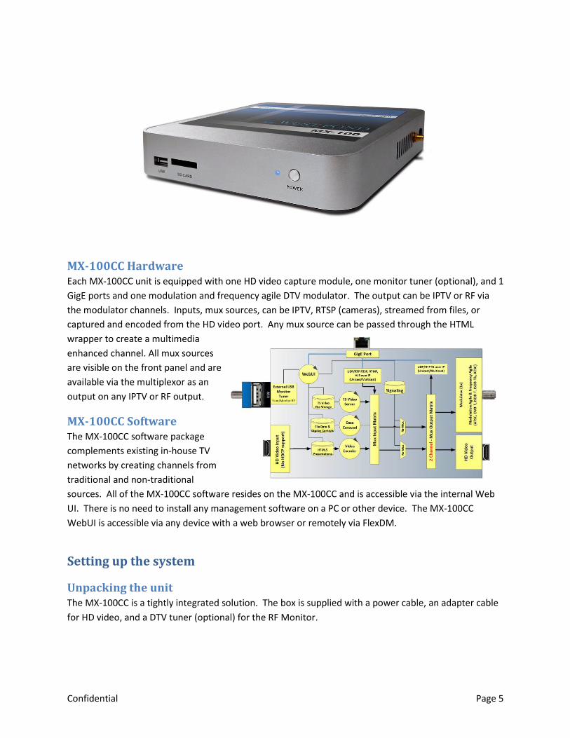
MX-100CC Hardware Each MX-100CC unit is equipped with one HD video capture module, one monitor tuner (optional), and 1
GigE ports and one modulation and frequency agile DTV modulator. The output can be IPTV or RF via
the modulator channels. Inputs, mux sources, can be IPTV, RTSP (cameras), streamed from files, or
captured and encoded from the HD video port. Any mux source can be passed through the HTML
wrapper to create a multimedia
enhanced channel. All mux sources
are visible on the front panel and are
available via the multiplexor as an
output on any IPTV or RF output.
MX-100CC Software The MX-100CC software package
complements existing in-house TV
networks by creating channels from
traditional and non-traditional
sources. All of the MX-100CC software resides on the MX-100CC and is accessible via the internal Web
UI. There is no need to install any management software on a PC or other device. The MX-100CC
WebUI is accessible via any device with a web browser or remotely via FlexDM.
Setting up the system
Unpacking the unit The MX-100CC is a tightly integrated solution. The box is supplied with a power cable, an adapter cable
for HD video, and a DTV tuner (optional) for the RF Monitor.
Confidential Page 6
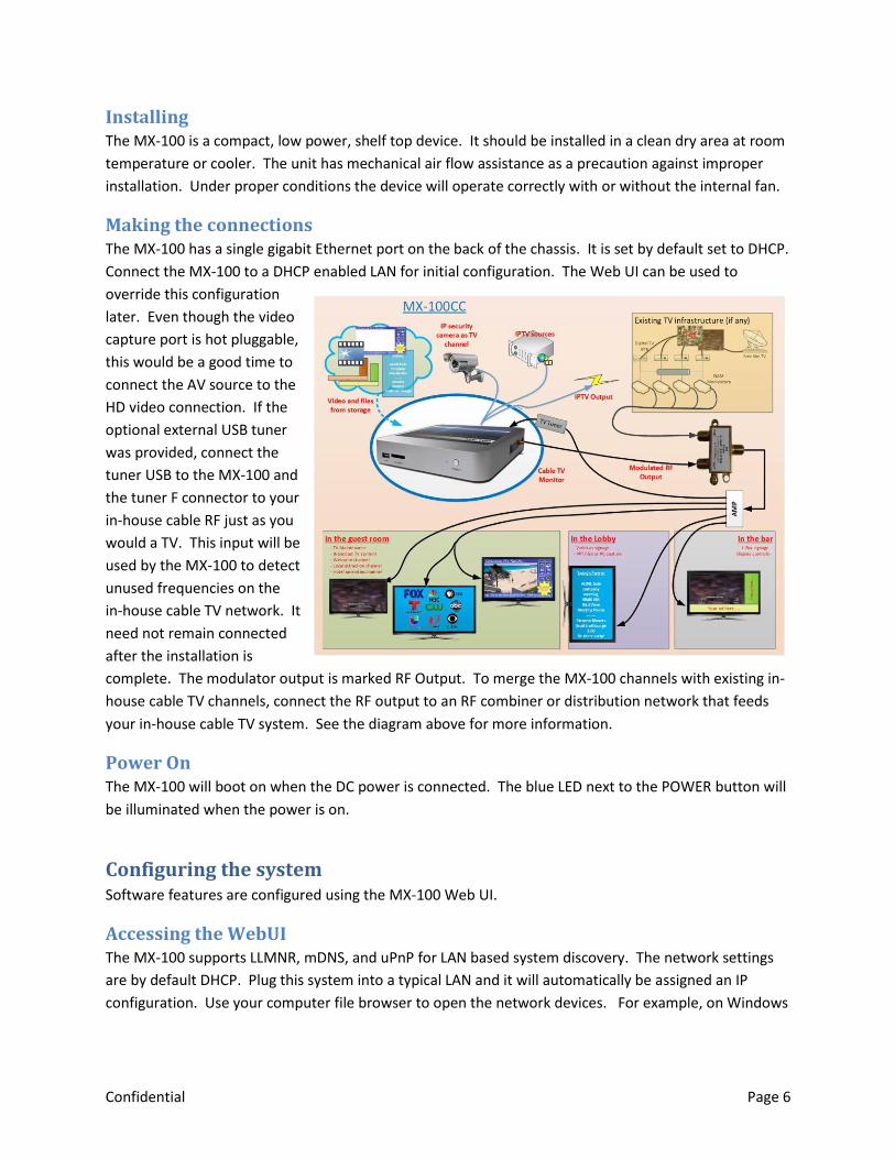
Installing The MX-100 is a compact, low power, shelf top device. It should be installed in a clean dry area at room
temperature or cooler. The unit has mechanical air flow assistance as a precaution against improper
installation. Under proper conditions the device will operate correctly with or without the internal fan.
Making the connections The MX-100 has a single gigabit Ethernet port on the back of the chassis. It is set by default set to DHCP.
Connect the MX-100 to a DHCP enabled LAN for initial configuration. The Web UI can be used to
override this configuration
later. Even though the video
capture port is hot pluggable,
this would be a good time to
connect the AV source to the
HD video connection. If the
optional external USB tuner
was provided, connect the
tuner USB to the MX-100 and
the tuner F connector to your
in-house cable RF just as you
would a TV. This input will be
used by the MX-100 to detect
unused frequencies on the
in-house cable TV network. It
need not remain connected
after the installation is
complete. The modulator output is marked RF Output. To merge the MX-100 channels with existing in-
house cable TV channels, connect the RF output to an RF combiner or distribution network that feeds
your in-house cable TV system. See the diagram above for more information.
Power On The MX-100 will boot on when the DC power is connected. The blue LED next to the POWER button will
be illuminated when the power is on.
Configuring the system Software features are configured using the MX-100 Web UI.
Accessing the WebUI The MX-100 supports LLMNR, mDNS, and uPnP for LAN based system discovery. The network settings
are by default DHCP. Plug this system into a typical LAN and it will automatically be assigned an IP
configuration. Use your computer file browser to open the network devices. For example, on Windows
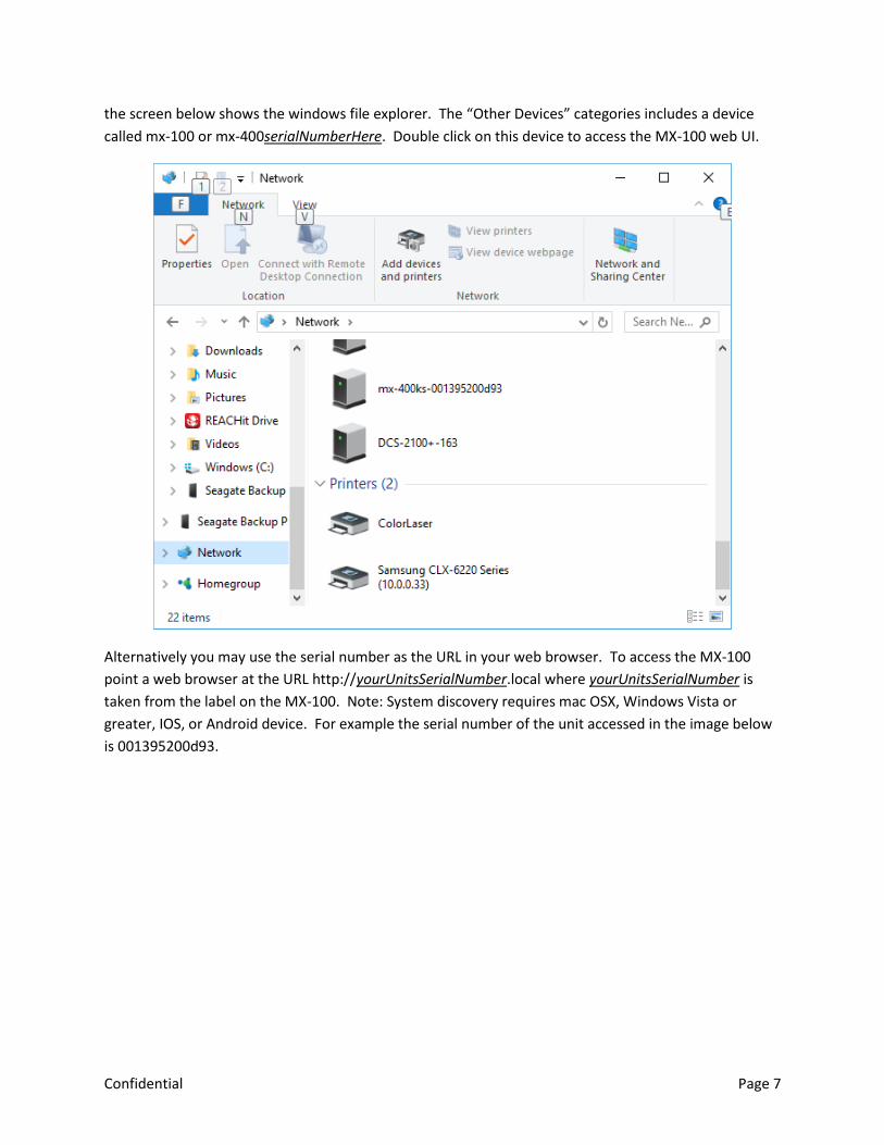
Confidential Page 7
the screen below shows the windows file explorer. The “Other Devices” categories includes a device
called mx-100 or mx-400serialNumberHere. Double click on this device to access the MX-100 web UI.
Alternatively you may use the serial number as the URL in your web browser. To access the MX-100
point a web browser at the URL http://yourUnitsSerialNumber.local where yourUnitsSerialNumber is
taken from the label on the MX-100. Note: System discovery requires mac OSX, Windows Vista or
greater, IOS, or Android device. For example the serial number of the unit accessed in the image below
is 001395200d93.

Confidential Page 8
Once connected, you will be prompted to login. Use the administrator credentials
User: Administrator Password: admin
Note: Firefox and Chrome preferred.
There are three built-in users. The passwords for these users can be set by the administrator.
Administrator: Used by installer to configure and manage the system. This user has access to all
controls and settings.
Operator: Used by less technical personal to access and change the video wrapper content. This
user can view nearly all settings but can only control those features that need to be changed during
a game or event.
Monitor: Read only access. Used by anyone who has an interest in the technology but should not be
making any configuration changes to the system.
Getting familiar with the MX-100 The West Pond product team may preconfigure your device to provide a head start for your particular
application. This may include the installation of template presentations, test videos, and the
configuration of input and output streams. The IP addresses used for IP inputs and outputs are likely

Confidential Page 9
inappropriate for your installation and may need reconfiguring. In this section we will review how to
make small changes to these settings to get your system running as quickly as possible.
Overview The top level page of the WebUI provides an
overview of the MX-100 scalable multiplexor.
The multiplexor combines digital AV streams
from a variety of sources into groups and
transmits them with the correct signaling and
timing to the appropriate output. Outputs
may have constraints, such as bitrate and
signaling, that must be configured to operate
correctly. To preserve resources, inputs are
only processed if enabled. A mapping
between inputs and outputs is shown in the
overview menu of the MX-400 WebUI. The
sources (aka enabled inputs) are shown on the left, outputs are shown on the right. The sources tab
groups the source transports by the input while the output tab shows this mapping grouped by
destination (output). There is a variety of information on these pages that can be valuable when trying
to diagnose a problem. Error indicators are shown when a problem has been detected with a
particular input or output stream. On the screen image above there is an error showing that the
output transport is oversubscribed. i.e. Utilization is over 100%. This should be rectified to avoid video
artifacts.
Fingernail images captured from the video are periodically updated next to each input/output. This
helps to provide context when configuring your system. These update slowly so as to ensure they do
not steal any computational resources from the system.
Confidential Page 10
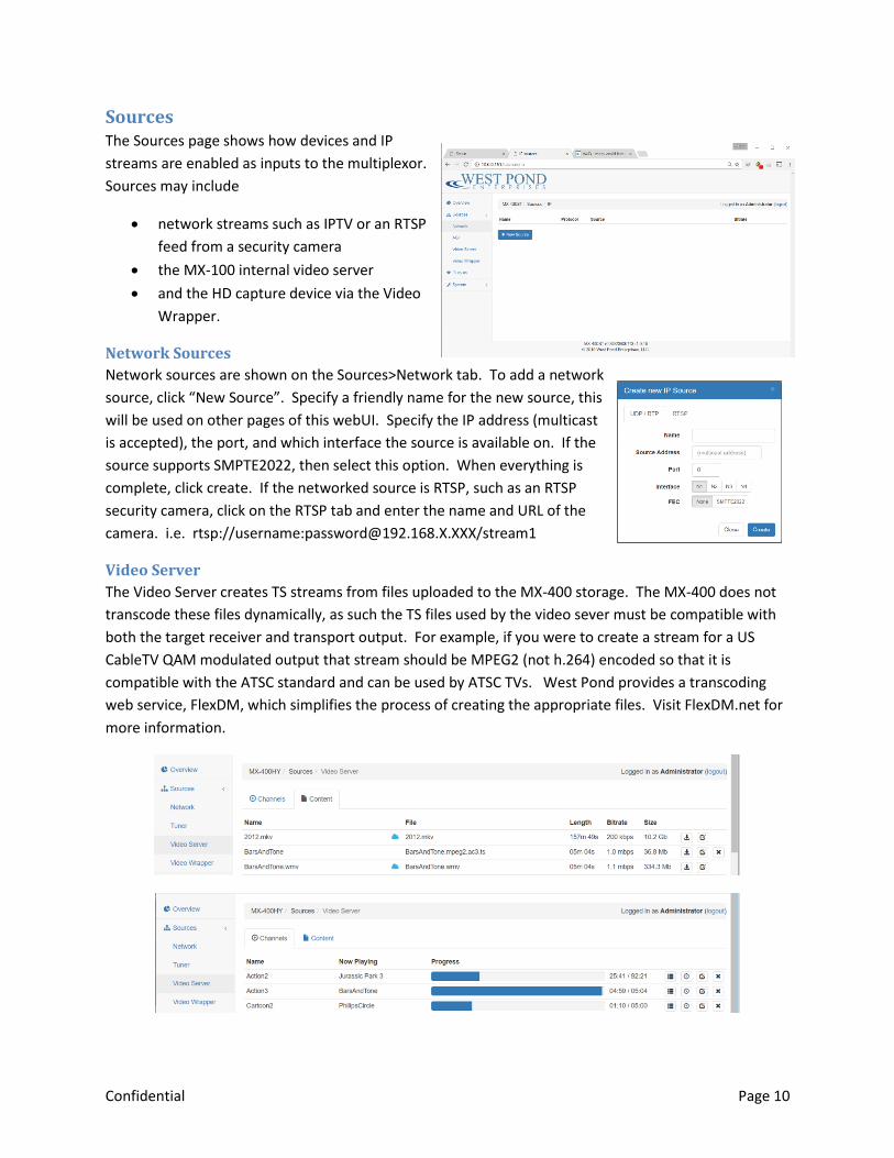
Sources The Sources page shows how devices and IP
streams are enabled as inputs to the multiplexor.
Sources may include
network streams such as IPTV or an RTSP
feed from a security camera
the MX-100 internal video server
and the HD capture device via the Video
Wrapper.
Network Sources
Network sources are shown on the Sources>Network tab. To add a network
source, click “New Source”. Specify a friendly name for the new source, this
will be used on other pages of this webUI. Specify the IP address (multicast
is accepted), the port, and which interface the source is available on. If the
source supports SMPTE2022, then select this option. When everything is
complete, click create. If the networked source is RTSP, such as an RTSP
security camera, click on the RTSP tab and enter the name and URL of the
camera. i.e. rtsp://username:[email protected]/stream1
Video Server
The Video Server creates TS streams from files uploaded to the MX-400 storage. The MX-400 does not
transcode these files dynamically, as such the TS files used by the video sever must be compatible with
both the target receiver and transport output. For example, if you were to create a stream for a US
CableTV QAM modulated output that stream should be MPEG2 (not h.264) encoded so that it is
compatible with the ATSC standard and can be used by ATSC TVs. West Pond provides a transcoding
web service, FlexDM, which simplifies the process of creating the appropriate files. Visit FlexDM.net for
more information.

Confidential Page 11
The “Content” tab shows the files that have been uploaded and may be used in any channel playlist.
Content with the icon are managed by the FlexDM service. The Channels tab shows the channels
created and the status of their playback. Create channels and upload content using the appropriate
buttons at the bottom of the screen. Once created TS files are assigned to a channel using the
button for looping playlists and the icon for scheduled content.
Video Wrapper
The Video Wrapper is a multiplexer input created
by combining captured (HDMI or HD-SDI) video
with HTML5 graphics. This resulting video is
prepared for cable TV broadcast or IPTV
distribution using mpeg2 or h.264 encoding.
Video Wrapper “Sources”, usually two, are
automatically created by the MX-100. However,
the configuration for these sources may still need
to be tweaked to meet the needs of your output.
More on this topic later. There are three tabs on
the Video Wrapper page: Channels, Playlists, and
Presentations. Presentations are HTML5 sources that are included in
playlists. Playlist are a sequence of 0 or more presentations to be fed as
content input to the HTML5 browser for rendering. Channels are the
result of a playlist applied to a capture module input.
Presentations
Video Wrapper presentations are java script animated HTML5 web pages that define how the resulting
TV channel screen is partitioned into video, advertisements, score, social media photos, date/time,
temperature, menu boards, logos, and any other media you might want to present in the TV channel.
Choose from West Pond’s collection of Presentation Templates or modify one to create your own.
Templates can be very simple, for example overlaying a logo on the video, or complex such as a score
board with dynamic advertisements, logos, game score and clock. Most templates can be used without
making any HTML or java script changes.
This is done by replacing the presentation
template sample images with your own,
or using the presentation configuration
page to select a new image. Clicking on
launches the presentation
configuration web page specific to that
presentation. Use these web pages to
change the characteristics of the
Confidential Page 12
presentation. A help system is included. The MX-100CC system will be preloaded with a few useful
templates. More are available at http://www.westpond.com/templates
The best way to learn about this is to click on a few and see what can be done.
The presentations tab also allows you to:
Delete a presentation
Browse and modify files within a presentation (drag and drop)
Create a new presentation by copying an existing presentation
Download a presentation to your PC to edit it. (Zip file)
Preview a presentation in your browser (sans video)
Configure a presentation using the presentation specific configuration tool
Create a new presentation by uploading a Zip file with the appropriate files
The presentation preview launches the presentation in a browser window. This is a good way to
test your presentation changes. Run time errors, if there are any with your content as it is run in a
playlist, will be reported in the system log. This is also available in the webUI.
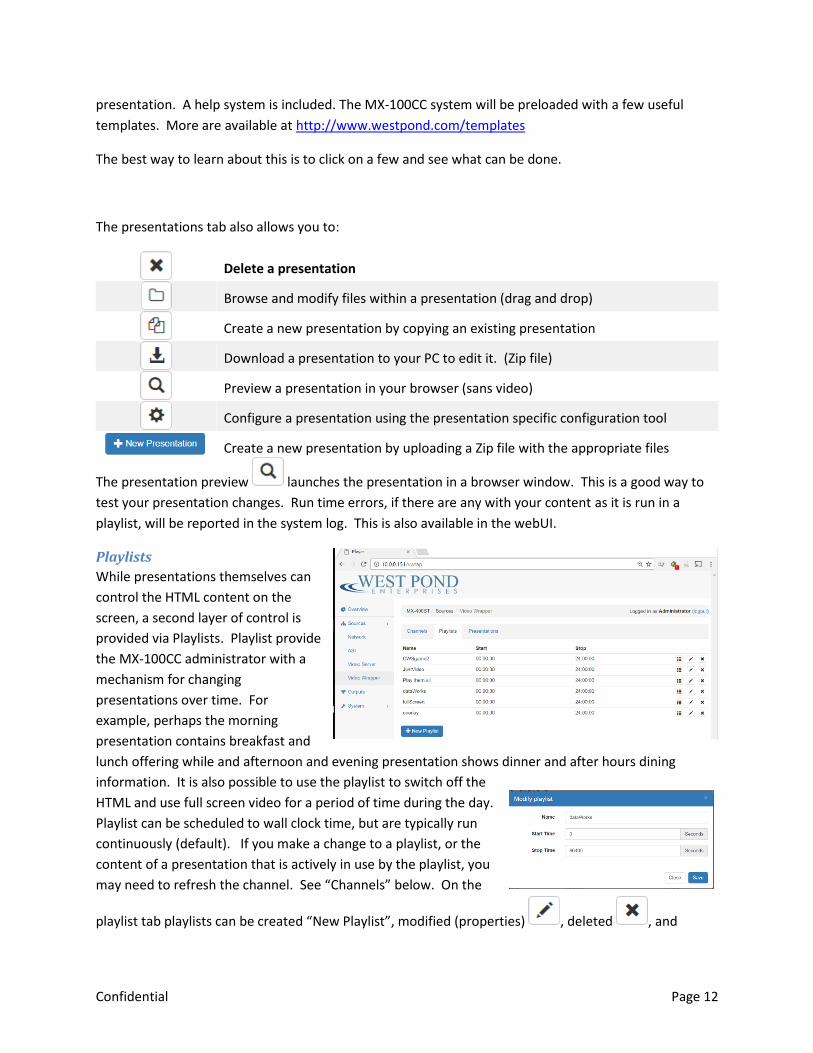
Playlists
While presentations themselves can
control the HTML content on the
screen, a second layer of control is
provided via Playlists. Playlist provide
the MX-100CC administrator with a
mechanism for changing
presentations over time. For
example, perhaps the morning
presentation contains breakfast and
lunch offering while and afternoon and evening presentation shows dinner and after hours dining
information. It is also possible to use the playlist to switch off the
HTML and use full screen video for a period of time during the day.
Playlist can be scheduled to wall clock time, but are typically run
continuously (default). If you make a change to a playlist, or the
content of a presentation that is actively in use by the playlist, you
may need to refresh the channel. See “Channels” below. On the
playlist tab playlists can be created “New Playlist”, modified (properties) , deleted , and
Confidential Page 13
edited (content) . Modifying a playlist allows the user to change the playlist name, start time (in
seconds where 0 is midnight) and stop time. The default settings, 0 and 86400 Seconds, will allow the
playlist to be active continuously.
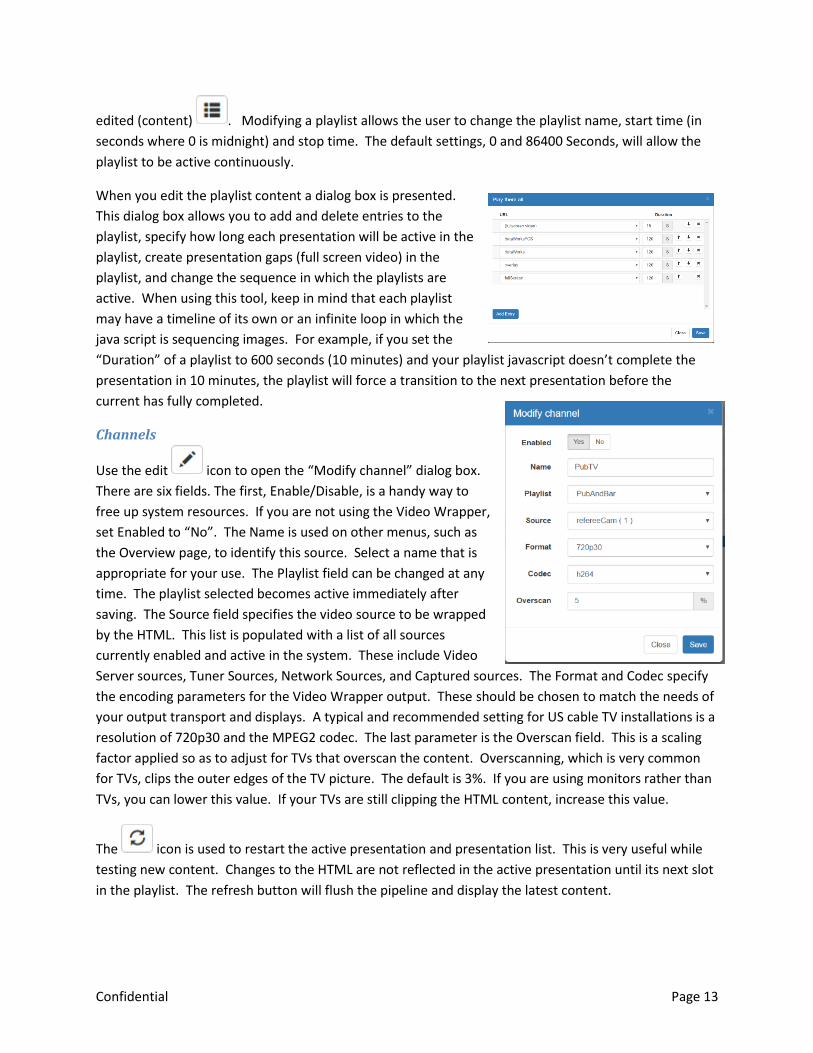
When you edit the playlist content a dialog box is presented.
This dialog box allows you to add and delete entries to the
playlist, specify how long each presentation will be active in the
playlist, create presentation gaps (full screen video) in the
playlist, and change the sequence in which the playlists are
active. When using this tool, keep in mind that each playlist
may have a timeline of its own or an infinite loop in which the
java script is sequencing images. For example, if you set the
“Duration” of a playlist to 600 seconds (10 minutes) and your playlist javascript doesn’t complete the
presentation in 10 minutes, the playlist will force a transition to the next presentation before the
current has fully completed.
Channels
Use the edit icon to open the “Modify channel” dialog box.
There are six fields. The first, Enable/Disable, is a handy way to
free up system resources. If you are not using the Video Wrapper,
set Enabled to “No”. The Name is used on other menus, such as
the Overview page, to identify this source. Select a name that is
appropriate for your use. The Playlist field can be changed at any
time. The playlist selected becomes active immediately after
saving. The Source field specifies the video source to be wrapped
by the HTML. This list is populated with a list of all sources
currently enabled and active in the system. These include Video
Server sources, Tuner Sources, Network Sources, and Captured sources. The Format and Codec specify
the encoding parameters for the Video Wrapper output. These should be chosen to match the needs of
your output transport and displays. A typical and recommended setting for US cable TV installations is a
resolution of 720p30 and the MPEG2 codec. The last parameter is the Overscan field. This is a scaling
factor applied so as to adjust for TVs that overscan the content. Overscanning, which is very common
for TVs, clips the outer edges of the TV picture. The default is 3%. If you are using monitors rather than
TVs, you can lower this value. If your TVs are still clipping the HTML content, increase this value.
The icon is used to restart the active presentation and presentation list. This is very useful while
testing new content. Changes to the HTML are not reflected in the active presentation until its next slot
in the playlist. The refresh button will flush the pipeline and display the latest content.
Confidential Page 14
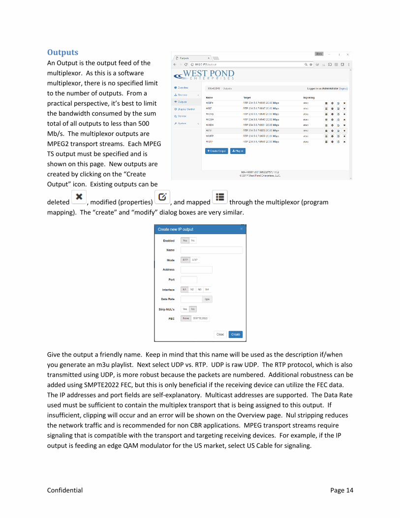
Outputs An Output is the output feed of the
multiplexor. As this is a software
multiplexor, there is no specified limit
to the number of outputs. From a
practical perspective, it’s best to limit
the bandwidth consumed by the sum
total of all outputs to less than 500
Mb/s. The multiplexor outputs are
MPEG2 transport streams. Each MPEG
TS output must be specified and is
shown on this page. New outputs are
created by clicking on the “Create
Output” icon. Existing outputs can be
deleted , modified (properties) , and mapped through the multiplexor (program
mapping). The “create” and “modify” dialog boxes are very similar.
Give the output a friendly name. Keep in mind that this name will be used as the description if/when
you generate an m3u playlist. Next select UDP vs. RTP. UDP is raw UDP. The RTP protocol, which is also
transmitted using UDP, is more robust because the packets are numbered. Additional robustness can be
added using SMPTE2022 FEC, but this is only beneficial if the receiving device can utilize the FEC data.
The IP addresses and port fields are self-explanatory. Multicast addresses are supported. The Data Rate
used must be sufficient to contain the multiplex transport that is being assigned to this output. If
insufficient, clipping will occur and an error will be shown on the Overview page. Nul stripping reduces
the network traffic and is recommended for non CBR applications. MPEG transport streams require
signaling that is compatible with the transport and targeting receiving devices. For example, if the IP
output is feeding an edge QAM modulator for the US market, select US Cable for signaling.

Confidential Page 15
A playlist.m3u file that describes all of the multicast outputs can be downloaded by
clicking on the playlist icon. For IPTV networks, session announcement protocol
(SAP RFC 2974 ) is supported and included in the stream when enabled.
Modulated RF Output
The modulator hardware is automatically detected and a list of available modulators is shown on the
Output page of the WebUI. All modulators are expected to transmit over the same cable network, as
such it is not necessary to identify how a modulator maps to a particular F connector.
To edit an RF output click on the associated config icon. Select the Channel from the list. It’s best to
be sure that the channel selected is not in use. If the
Channel/Frequency you wish to use is not on the list, you
may need to change the channel map. Select the Modulator,
the modulation standard, and the modulation type. The
power level should remain at 1 for most cabled
environments. If a value greater than 1 is required,
attenuators may be necessary for TVs that are receiving high
power signals. Attenuators or amplifiers should be used to
achieve optimal power within the cable distribution
network. Use this field post install to make minor power
level adjustments if required.
Program Mapping
Program Mapping is the heart of the multiplexor.
Clicking on the icon for a specific output will switch the Outputs page to a program mapping view
for that output. Mapping an input to an output can be done at the program level, or at the PID level. If
you are not intimately familiar with transport stream anatomy, stick with the program level and use the
default setting whenever they are provided.
Once in the Program Mapping view, all of the available multiplexor sources are listed on the left, each
with a mapping icon to the right. Click on the mapping icon and edit the mapping
appropriately for each program you would like included in this output. Programs included in the

Confidential Page 16
transport are highlighted with a green background and a green arrow. On the “Modify program
mapping” dialog box, select “Yes” if you wish this
source to be included in the output. Be mindful
of the bandwidth limitations of your chosen
output transport. If you oversubscribe, artifacts
may occur on any program in that transport.
More on this topic below. The Program Number
field is used when you wish to manually set the
program number for this program use this field.
If not using the “auto” selection for this field, be
sure to choose the program number carefully,
there cannot be any duplicate program numbers
in a given transport. The PMT pid and Elements
are for expert use only and should almost always
be “auto”. If the output is configured for US
Cable or ATSC, there are additional fields for PSIP
information. These fields contain data that is
often displayed on the TV when the channel is
first tuned. The Short Name can be up to 7
characters. i.e. WXYZ-12. The Virtual Channel information will typically override the Physical Channel
information when displayed on a TV. The Virtual Channel can be a single digit integer or hyphenated if
supplying both a major and minor channel number. You can return to this dialog later and modify these
fields at any time. All changes will take effect immediately. You may need to retune the TV to see the
results.
Oversubscribing the Transport
If the sum total bit rate for all the programs included the output multiplex is more than the specified
maximum bitrate for that transport, clipping will occur to ensure the output does not exceed the
maximum bitrate. Clipping means some packets are not transmitted. Missing packets will cause audio
and video artifacts in one or more of the programs included in that output transport. After selecting and
saving the programs that will be included in your output transport it is best to return to the Outputs tab
of the Overview page to see if the “Utilization” for that output is more than 100%. If it is, then the
number or mix of programs in that multiplex should be trimmed. At times, since video encoding is a
variable bitrate, these errors will be intermittent. To be save, it’s best not to exceed 90% of the
available bandwidth (“utilization”).
Confidential Page 17
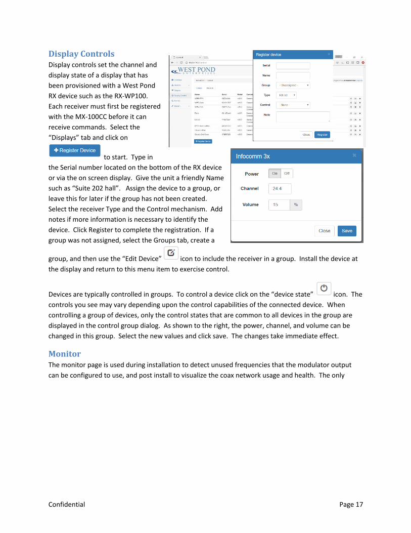
Display Controls Display controls set the channel and
display state of a display that has
been provisioned with a West Pond
RX device such as the RX-WP100.
Each receiver must first be registered
with the MX-100CC before it can
receive commands. Select the
“Displays” tab and click on
to start. Type in
the Serial number located on the bottom of the RX device
or via the on screen display. Give the unit a friendly Name
such as “Suite 202 hall”. Assign the device to a group, or
leave this for later if the group has not been created.
Select the receiver Type and the Control mechanism. Add
notes if more information is necessary to identify the
device. Click Register to complete the registration. If a
group was not assigned, select the Groups tab, create a
group, and then use the “Edit Device” icon to include the receiver in a group. Install the device at
the display and return to this menu item to exercise control.
Devices are typically controlled in groups. To control a device click on the “device state” icon. The
controls you see may vary depending upon the control capabilities of the connected device. When
controlling a group of devices, only the control states that are common to all devices in the group are
displayed in the control group dialog. As shown to the right, the power, channel, and volume can be
changed in this group. Select the new values and click save. The changes take immediate effect.
Monitor The monitor page is used during installation to detect unused frequencies that the modulator output
can be configured to use, and post install to visualize the coax network usage and health. The only

Confidential Page 18
configuration setting is the channel
map chosen. The default is US
Cable TV. The monitor will tune to
each of the frequencies in the
chosen channel map and report the
status. An empty row indicates an
unused frequency. The caution icon
indicates the presence of
some signal, perhaps noise or an
unknown modulation. A used
frequency band will have a green
signal icon. Frequency bands
that are in use may also have additional information if such information is available on the frequency.
When selecting a frequency band for the output modulator you will achieve the best results if you
choose one that has no signal at all. If none are available, one of the caution bands may be acceptable.
System The System page is used for
configuring and monitoring system
level features of the MX-100
system.
Settings
This page provides a more
comprehensive view into the
system configuration of the MX-
100.
Network: The network
configuration is shown both here and on the front panel. Changes may be made on either UI. Click on
the gear icon to configure any one of the four network ports. Ports configured and linked will have
a green icon. Red icons indicate an error. No icon indicates the port is disabled.
NTP: Use the icon to configure the network time server.
System Name: Use the icon to set the system name. This name will be displayed on the front panel
and on the webUI.
Timezone: Use the icon to set the timezone in which the server is being used. This is very
important when scheduling playback and other time critical WebUI features.
Confidential Page 19
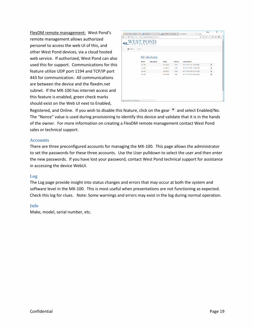
FlexDM remote management: West Pond’s
remote management allows authorized
personel to access the web UI of this, and
other West Pond devices, via a cloud hosted
web service. If authorized, West Pond can also
used this for support. Communications for this
feature utilize UDP port 1194 and TCP/IP port
443 for communication. All communications
are between the device and the flexdm.net
subnet. If the MX-100 has internet access and
this feature is enabled, green check marks
should exist on the Web UI next to Enabled,
Registered, and Online. If you wish to disable this feature, click on the gear and select Enabled/No.
The “Nonce” value is used during provisioning to identify this device and validate that it is in the hands
of the owner. For more information on creating a FlexDM remote management contact West Pond
sales or technical support.
Accounts
There are three preconfigured accounts for managing the MX-100. This page allows the administrator
to set the passwords for these three accounts. Use the User pulldown to select the user and then enter
the new passwords. If you have lost your password, contact West Pond technical support for assistance
in accessing the device WebUI.
Log
The Log page provide insight into status changes and errors that may occur at both the system and
software level in the MX-100. This is most useful when presentations are not functioning as expected.
Check this log for clues. Note: Some warnings and errors may exist in the log during normal operation.
Info
Make, model, serial number, etc.
Confidential Page 20
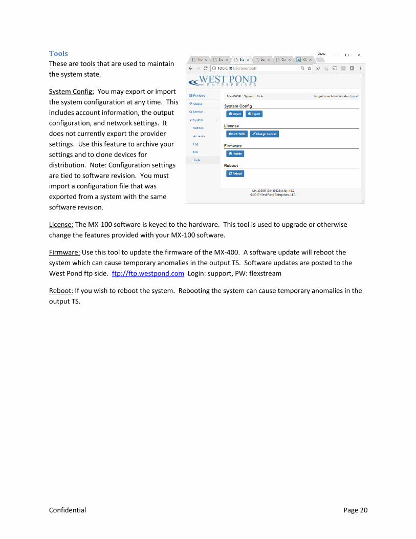
Tools
These are tools that are used to maintain
the system state.
System Config: You may export or import
the system configuration at any time. This
includes account information, the output
configuration, and network settings. It
does not currently export the provider
settings. Use this feature to archive your
settings and to clone devices for
distribution. Note: Configuration settings
are tied to software revision. You must
import a configuration file that was
exported from a system with the same
software revision.
License: The MX-100 software is keyed to the hardware. This tool is used to upgrade or otherwise
change the features provided with your MX-100 software.
Firmware: Use this tool to update the firmware of the MX-400. A software update will reboot the
system which can cause temporary anomalies in the output TS. Software updates are posted to the
West Pond ftp side. ftp://ftp.westpond.com Login: support, PW: flexstream
Reboot: If you wish to reboot the system. Rebooting the system can cause temporary anomalies in the
output TS.

Confidential Page 21
Appendix A – Quick Start Help This section is provided to enable installers with a check list of things to do when installing the system.
1) Mount the device and make all the required connections. Power the system on. For more
information follow the instruction above in the section: Setting up the system.
2) Using Window File explorer, or equivalent, and select Network to find the MX-100. There will be
a device in “other devices” that has the same name as the model number. Double click on the
icon to access the WebUI. See Accessing the WebUI for more information on this topic
3) Enable and configure Sources to the multiplexer. You need not configure them all at this point.
You can easily add more later.
a. Sources may include Tuners, IPTV, RTSP cameras, Video Capture, or the Video Server
b. Details for each are provide in the Sources section of the main document.
c. When configuring a tuner source you will need information about the broadcast before
configuring.
i. Cheat: Attach the antenna wire to the M1 monitor input and watch the monitor
results to find tunable frequencies. This will likely require a channel map change
in the monitor configuration. Remember to reconfigure M1 to monitor your
outputs before completing the setup of your system.
d. When configuring the Video Server, be sure that your TS files are compatible with the
devices receiving the output of the MX-100CC. For example, if using and ATSC
modulated output you must use MPEG2 encoded files. ATSC devices will not decode
h.264 video.
e. If enabling the Video Server source, try one of the preloaded MPEG2 or h.264 files
before loading your own.
f. If enabling the Video Wrapper source, try one of the preloaded presentations and
playlists before testing your own.
g. All of the enabled multiplexer inputs can be viewed on the front panel. Use this to
verify you have correctly configured your inputs.
4) Enable and configure Outputs of the multiplexer.
a. Outputs may include IPTV or RF.
b. Create Outputs first, then select the “Program Mapping” icon to configure their
contents.
c. When creating an RF output, utilize the Monitor page to find unused carrier frequencies.
d. When selecting the “Program Mapping” be sure of the following:
i. All of the sources selected are compatible with the receiving device. i.e. If ATSC,
all of the included program streams should be MPEG2 encoded video.
ii. The sum of all enabled sources should not exceed the maximum bitrate of the
Output transport. i.e. If ATSC 8-VSB do not exceed 19.39 Mb/s. Check the
outputs tab of the overview page to see signs of over subscription.
5) Check the results
a. All multiplexer video sources should be visible on the front panel.
b. Have a receiving device ready to test the results.
Confidential Page 22
Appendix B – FAQs
How do I create a TV channel from a video file?
Video files can be transcoded into TS files that can then be sources to the MX-xxx multiplexor and
transmitted over any of the multiplexor outputs. The steps to creating a channel from a video files are:
1) Transcode the video file into a TS file that is suitable for your output transport and receiving
devices. (bitrate, encoding, resolution)
2) Download the file to the MX-xxx storage
3) Create a Video Server streaming video channel
4) Include the transcoded file in the channel playlist
5) Modify the multiplexor Output to include the Video Server channel
Step 1 & 2: Transcode
Transcoding is the most complicated step toward creating your own video server channel. We strongly
encourage using the FlexDM service to ensure that the resulting file is both compatible and optimal for
the chosen transport and receivers. The FlexDM.net web service allows you to manage devices and
upload videos that will be transcoded and downloaded to the device directly. Log in to FlexDM.net to
create an account and start managing your video streams. Then skip to Step 3.
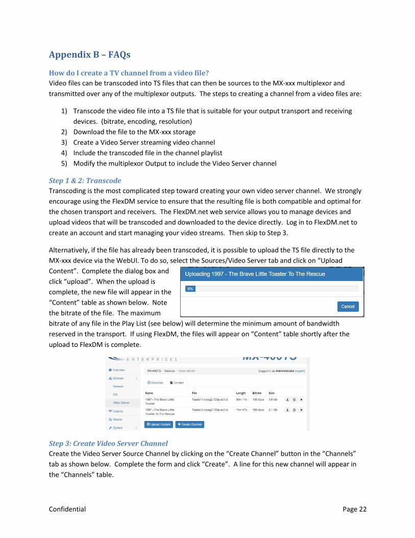
Alternatively, if the file has already been transcoded, it is possible to upload the TS file directly to the
MX-xxx device via the WebUI. To do so, select the Sources/Video Server tab and click on “Upload
Content”. Complete the dialog box and
click “upload”. When the upload is
complete, the new file will appear in the
“Content” table as shown below. Note
the bitrate of the file. The maximum
bitrate of any file in the Play List (see below) will determine the minimum amount of bandwidth
reserved in the transport. If using FlexDM, the files will appear on “Content” table shortly after the
upload to FlexDM is complete.
Step 3: Create Video Server Channel
Create the Video Server Source Channel by clicking on the “Create Channel” button in the “Channels”
tab as shown below. Complete the form and click “Create”. A line for this new channel will appear in
the “Channels” table.
Confidential Page 23
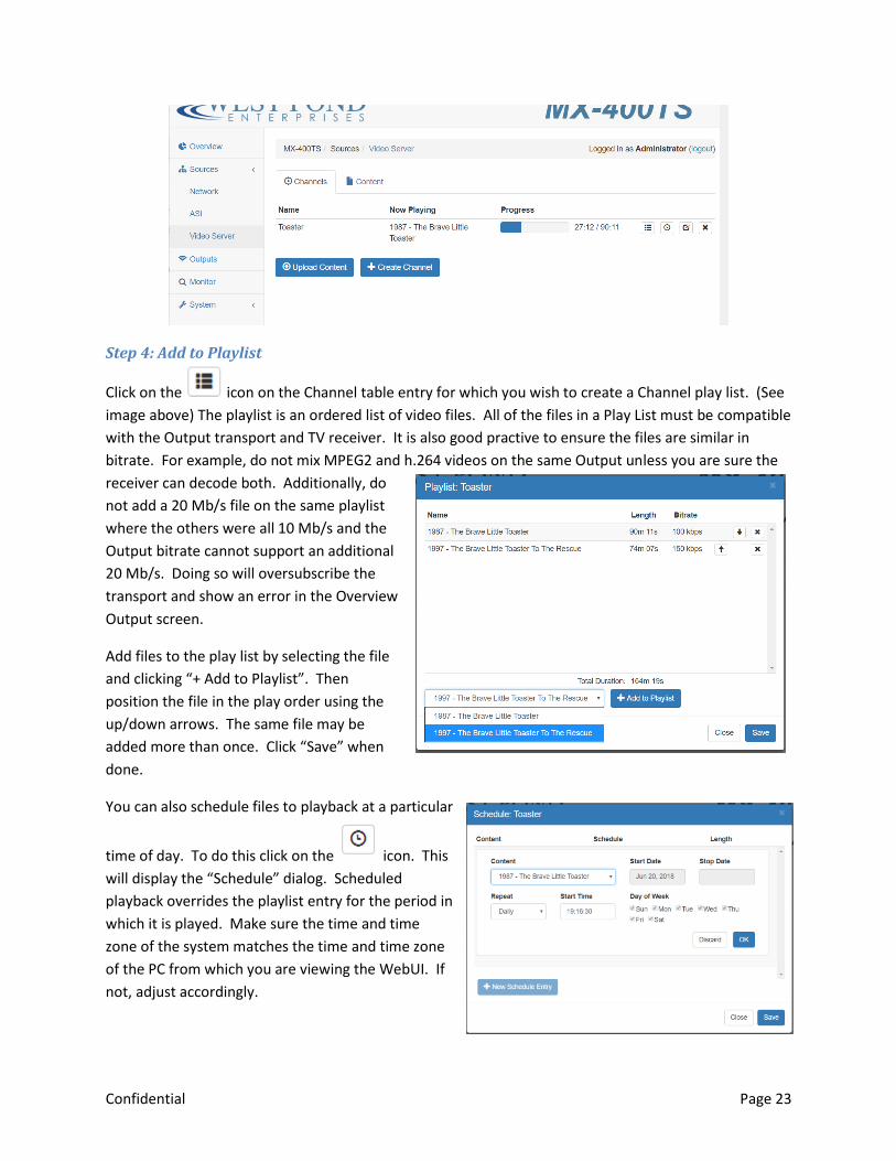
Step 4: Add to Playlist
Click on the icon on the Channel table entry for which you wish to create a Channel play list. (See
image above) The playlist is an ordered list of video files. All of the files in a Play List must be compatible
with the Output transport and TV receiver. It is also good practive to ensure the files are similar in
bitrate. For example, do not mix MPEG2 and h.264 videos on the same Output unless you are sure the
receiver can decode both. Additionally, do
not add a 20 Mb/s file on the same playlist
where the others were all 10 Mb/s and the
Output bitrate cannot support an additional
20 Mb/s. Doing so will oversubscribe the
transport and show an error in the Overview
Output screen.
Add files to the play list by selecting the file
and clicking “+ Add to Playlist”. Then
position the file in the play order using the
up/down arrows. The same file may be
added more than once. Click “Save” when
done.
You can also schedule files to playback at a particular
time of day. To do this click on the icon. This
will display the “Schedule” dialog. Scheduled
playback overrides the playlist entry for the period in
which it is played. Make sure the time and time
zone of the system matches the time and time zone
of the PC from which you are viewing the WebUI. If
not, adjust accordingly.
Confidential Page 24
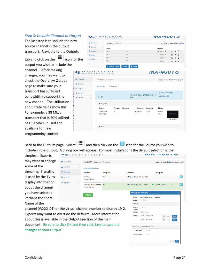
Step 5: Include Channel in Output
The last step is to include the new
source channel in the output
transport. Navigate to the Outputs
tab and click on the icon for the
output you wish to include the
channel. Before making
changes, you may want to
check the Overview Output
page to make sure your
transport has sufficient
bandwidth to support the
new channel. The Utilization
and Bitrate fields show this.
For example, a 38 Mb/s
transport that is 50% utilized
has 19 Mb/s unused and
available for new
programming content.
Back to the Outputs page. Select and then click on the icon for the Source you wish to
include in the output. A dialog box will appear. For most installations the default selection is the
simplest. Experts
may want to change
some of the
signaling. Signaling
is used by the TV to
display information
about the channel
you have selected.
Perhaps the short
Name of the
channel (WXXX-DT) or the virtual channel number to display 19-2.
Experts may want to override the defaults. More information
about this is available in the Outputs section of the main
document. Be sure to click OK and then click Save to save the
changes to your Output.