recombination models a. the holliday junction model
TRANSCRIPT

Recombination Models A. The Holliday Junction Model
Fig. 1 illustrates the formation of a Holliday junction (I) and its branch migration (II). The branch point (the blue ‘X’) at the left in I has moved towards its right to give II. Note that symmetric heteroduplex (red/ green) is formed during branch migration. The Holliday junction in III is identical to that in II, except that it is in the antiparallel geometry. In II, A-b and a-B are in the left to right orientation. In III, a-B is in the right to left orientation. This can be done by rotating the bottom DNA through 180 degrees about an axis at the junction, and in the plane of the paper. This operation changes the ‘X’ form junction in II to an ‘H’ form junction in III. Color codes: Parental DNA molecules, Red and Green.

The Top strands (one pair of equivalent strands in the red and green DNA)
are shown by thick lines. The complementary strands (the second pair of
equivalent strands) are drawn as thin lines. The blue lines are phosphodiester
bonds. Each blue line is a single phopshodiester bond regardless of how long
or short it appears in the diagrams.
B. Structural Manipulations of the Holliday Junction
Fig. 2 Let us take junction III from Fig. 1 (top panel in Fig. 2), and stack the arms
differently. Pull up arms A and b, and pull down arms B and a. The

junction will now take up the form shown in the middle panel of Fig. 2. Arm
A is stacked over arm B; arm b is stacked over arm a. If you like, rotate
the whole junction through 90 degrees clockwise, so that it looks more like
the junction at the top.
Notice that it is the thin strands that are crossed in the junction at the
top; and it is the thick strands that are crossed in the junction at the
bottom.
Resolve the junction at the top by cutting the crossed thin strands (or
the phosphodiester bonds indicated by the long blue lines). Notice that
each DNA product carries the heteroduplex (symmetric), and each has the
flanking markers in the parental configuration (A over b and a over B).
Now, resolve the junction at the bottom, also by cutting the crossed
(thick) strands (or the phosphodiester bonds indicated by the long blue
lines). Each product has the same symmetric heteroduplex as before.
However, the flanking markers are in the crossed-over or recombined
configuration (A over B and a over b). Here is a common sense rule:
If you form the Holliday junction by crossing one pair of strands (say, the thin strands in the diagrams), and if you resolve the junction by cutting the same pair of strands (again the thin strands), there will be no cross-over of the flanking markers. Remember, each DNA partner has two strands, and you have to cross both of them to get recombination (or all four strands for two duplexes involved in genetic exchange). If you cross a pair of strands (for Holliday formation), and cross the same pair again (for Holliday resolution), you have reversed the effect of the first crossing. Or, you go back to the parental state.
If you first cross the thin strands and then resolve the junction by
crossing the thick strands, you get cross-over of the flanking markers.
Notice that you have now crossed all four strands: first the two thin
strands, and then the two thick strands.
C. One last gyration of the Holliday junction Let us take the branch-migrated ‘X-form’ junction (II in Fig. 1) and place it
alongside its isomerized H form at the bottom of Fig. 2 (see Fig. 3). Let us rotate
the a-b cylinder (the bottom duplex) through 180 degrees about an axis at the

junction and in the plane of the paper. The resulting Holliday junction has now
the ‘X-form’. Let us call this junction IV.
Junction IV
Notice that the ‘X’ is formed by the thick strands in IV, whereas it is
formed by the thin strands in II. Also, the flanking markers in the top duplex in
II are A and b; they are A and B in II. Similarly, the flanking markers for the
bottom duplex in II (B and a) have now switched to a and b in IV.

D. The Meselson-Radding Model
Fig. 4 illustrates the model. The strand nick is made in one of the two duplexes. The nicked strand (green), the donor of genetic information, is used to invade the red partner, resulting in a D-loop in the recipient duplex. With extension of the heteroduplex, the D loop is expanded. The gap in the green DNA is filled by repair synthesis. The D-loop is chewed away (black slashes), and the nicks are closed. A Holliday junction is formed at the end point of the heteroduplex. Note that the heteroduplex (red/green) is present only on one duplex but not the other (or it is asymmetric).
Note that branch migration of the Holliday junction can generate
symmetric heteroduplex on either side of the Meselson-Radding region
(asymmetric heteroduplex).

E. The Double Strand Gap Repair Model
The model is diagrammed in Fig. 5. The green DNA, which is the recipient of information, is broken and gapped. Unequal DNA degradation in the two strands generate 3’ extensions which can invade the red duplex. The extruded strand (thin red) is a D-loop. Repair synthesis (dashed lines) and end joining results in two Holliday junctions. Since the missing green information is replaced by using the intact red DNA as template, the genetic information is all red in the gap-repair region. The borders of this region are
indicated by the vertical dashed black lines.
Between the right border of gap repair and the right Holliday junction,
you can see asymmetric heteroduplex (red/green on the top duplex).
Similarly, between the left border of gap repair and the left Holliday junction,
there is asymmetric heteroduplex (red/green on the bottom duplex).
Note that this model is inclusive of the Meselson-Radding model
(asymmetric heteroduplex) and the Holliday model (symmetric heteroduplex).

F. Recombination Models and Segregation Patterns
Apply the models to the four chromatid stage of the meiotic cell. Remember
that there are two chromosomes with red DNA in the region of interest to us,
and two chromosomes with green DNA in the same region. We consider
exchange between a red DNA duplex and a green DNA duplex as
diagrammed in the models, and arrive at the consequences of the exchange
on the segregation pattern.
1. Holliday model----------> Symmetric heteroduplex --------- > Two colonies
with half-sectors in yeast by germination of the four spores from a meiotic
event; two pairs of non-identical sister spores in Ascobolus. 4: 4 aberrant
segregation.
2. Meselson-Radding model ----- Asymmetric heteroduplex------ One half-sectored colony in yeast; One pair of non-identical sister spores in Ascobolus. 5:3 segregation 3. Double Strand Break Repair model----- Conversion of green DNA to red DNA in the gap repaired region----- 6:2 segregation.

Single Strand Annealing
When a double strand is made between two repeated sequences oriented in the same
direction, degradation of DNA from the ends will generate single stranded extensions
containing the homologous regions, now as complementary regions. They can anneal
by base-pairing, and repair of extra DNA by nucleases and gap filling by DNA synthesis
will restore the DNA duplex.
In budding yeast, S. cerevisiae, a double strand break in a chromosome or plasmid
can be delivered at a particular locus using the endonuclease called HO. [HO is a yeast
coded protein, which triggers a recombination/repair event responsible for switching the
mating type of an ‘a’ cell to ‘alpha’ or vice versa. HO = homothallic switching].

In an experimental set up, one can place the URA3 gene between two directly
repeated loci. After inducing the double strand break between the two loci, the repair by
the SSA pathway predicts that the URA 3 gene will be lost during processing and repair.
The ura-minus phenotype can be revealed on 5-FOA (5-fluoro-orotic acid) plates. 5-
FOA kills cells containing the URA3 gene. [Ask me how; I shall explain in class]. The
fulfillment of the predicted URA3 deletion supports the SSA model.
Another test for the predicted processing of ends by the SSA model is to place three copies
of the DNA cassette A, B and C as direct repeats, and induce the double strand break
between B and C, as shown in the diagram here. One can then ask how often B was used
as the template for repair compared to A. That is, was the DNA between B and C was deleted or the DNA between A and C (including B) was deleted. The experimental
observation was that the repair shown at the right was much more frequent than the repair
shown at the left. In other words, when the deletion exposes the complementary strands,
they anneal and trigger downstream events for the repair to be completed.

Genetic Requirements for SSA in budding yeast
(you need not remember all the genetic requirements for SSA)
RAD52. Rad52 protein is required for nearly all types of recombination/repair, including
SSA. It is a DNA binding protein that promotes annealing of single stranded DNA in
vitro. The requirement for Rad52 can be partially alleviated when the repeated
sequence is present in multiple copies (thus increasing the amount of DNA homology).
RAD59. A homolog of RAD52, RAD59, is also required for SSA. Purified Rad59 protein
possesses DNA binding properties and strand annealing activity.
RPA. Rpa is a protein that binds single stranded DNA, and is also required for SSA. RAD50, MRE11, XRS2. Rad50 protein forms a complex with two other proteins
involved in double strand break-repair, Mre11 and Xrs2. In the absence of Rad50 or
Xrs2, the repair takes longer and the amount of the repaired product is reduced.
Recombination genes not required for SSA RAD51, RAD54, RAD55 and RAD57. Rad51 is the homolog of the bacterial recA
protein, and is involved in the pairing of homologous DNA. It is required for double
strand break repair using a homologous template (a homologous chromosome or a
sister chromatid). Rad54, Rad55 and Rad57 are also required for homology-dependent
double strand break repair. None of these proteins are required for SSA.
Mismatch Repair Proteins and RAD1-RAD10. The mismatch repair proteins Msh2 and
Msh3 as well as Rad1 and Rad10 are required for efficient SSA and appear to be needed
to remove the non-homologous 3' tails from the annealed intermediate. Msh2 and Msh3
form a complex in vivo and have a strong preference for recognizing "loop-out" structures
such as those formed by frame shift replication errors. Msh2 and Msh3 probably bind to

the branched junction between the single and double stranded DNA. The complex
stabilizes the annealed intermediate and/or signals the Rad1-Rad10 endonuclease to
cleave the single stranded tail.
Biological Role. A DNA repair mechanism that deletes chromosomal DNA, which is what
occurs in the case of SSA, would not seem to be selectively advantageous. Removal of
essential loci would be lethal in a haploid organism and either lethal or detrimental in a
diploid organism. Perhaps, SSA is a useful mode of repair when the double strand break

12
occurs within a repeated array of genes such as the cluster of ribosomal DNA repeats. It
may also provide an alternative repair mechanism, albeit a risky one, if the more faithful
mechanisms of repair (double strand break repair) fail to occur for one reason or the other.
Synthesis Dependent
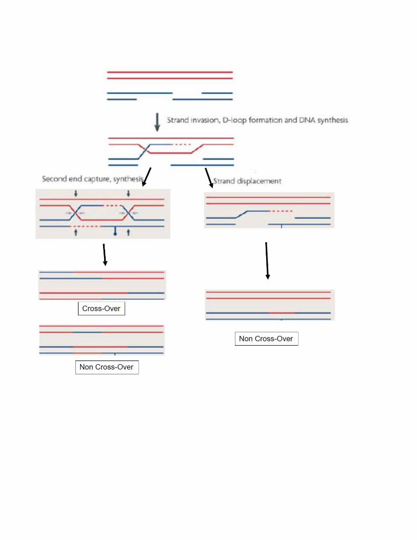
Strand Annealing
This pathway for repair of double strand breaks closely parallels that proposed by Rothstein-Szostak-Stahl (which we already discussed). The difference between the two
is that in synthesis dependent strand annealing (SDSA), the double Holliday junction is
not formed. The cross-over (CO in the figure below) of flanking markers during repair is
most easily explained by how the Holliday junctions are resolved. If there are no
Holliday junctions to resolve, the simple prediction is that there will be no cross-over
(NCO in the figure below) of flanking markers.
As shown in the diagram, the gapping of the double strand break and the
initiation of repair are similar for the classical double strand break repair (DSBR) and
the SDSA pathways. The difference comes after part of the gap has been repaired
using the intact duplex as the template. The extended strand is expelled and the D-
loop collapses. The overlapping regions of the gapped DNA anneal, and the remaining
gaps are filled by repair synthesis. At the end of repair, the flanking markers remain in
their parental configuration. Furthermore, hetero-duplex DNA (red/blue) flanking the
region of repair is not shared by both the duplexes after they are resolved (as in the
DSBR model). The repaired region, present only in the DNA that is the recipient of
information, can be homo-duplex (red/red) or hetero-duplex (red/blue), depending on
the extent of primed DNA synthesis on the two stands of the recipient duplex.