reactive energy managementtechmech.yolasite.com/resources/schneider meher reactive ene… ·...
TRANSCRIPT
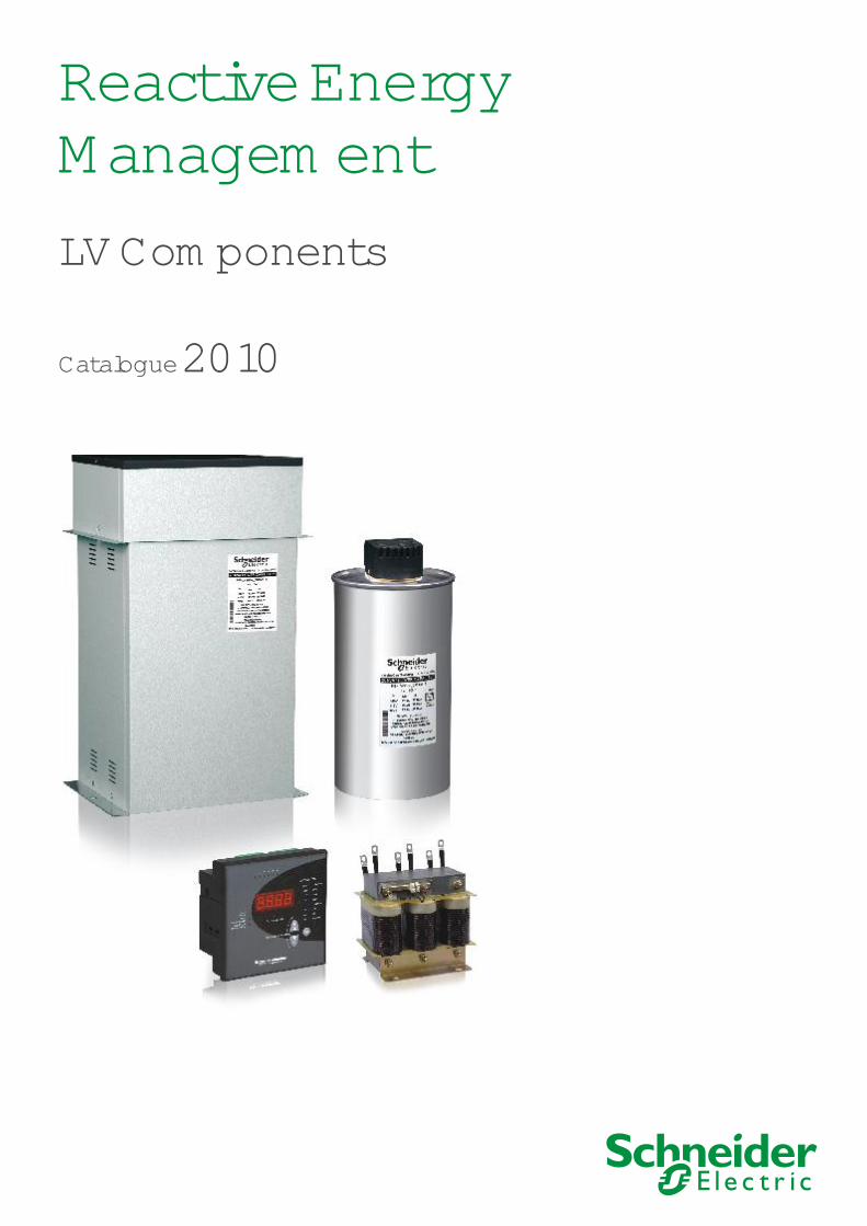
Reactive Energy ManagementLV Components
Catalogue 2010
Reduce energy cost and Improve your business performance
Ensure reliability and safety on installations Thanks to the know-how developed over the last 50 years, Schneider Electric is placed as the global specialist in Energy management providing a unique and comprehensive portfolio.
Schneider Electric helps you to make the most of your energy with innovative, reliable and safe solutions with:
Quality and reliability
l
l
l
Efficiency and productivityl
l
l
l
l
l
Continuity of service thanks to the high performance and long life expectancy of capacitors100% tested in manufacturing plant at BangaloreDesigned and engineered with the highest international standards
Tested safety features integrated on each phase. Over-pressure detection system for safe disconnection at the end of lifeAll the materials and components are non PCB pollutants
Product development includes innovation in ergonomics and ease of installation and connectionSpecially designed components to save time on installation and maintenanceAll the components and solutions are available through a network of distributors and partners in more than 100 countries
Safety
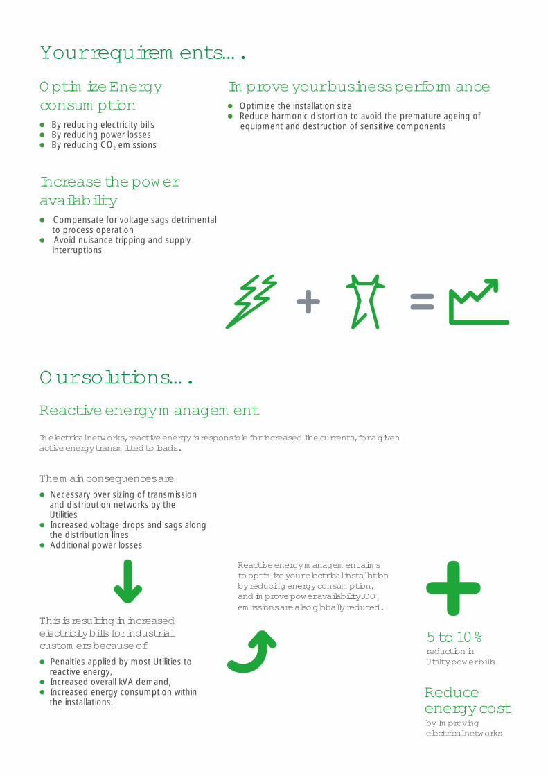
Your requirements….Optimize Energy consumption
Increase the power availability
l
l
l
l
l
By reducing electricity billsBy reducing power lossesBy reducing CO emissions2
Compensate for voltage sags detrimental to process operation Avoid nuisance tripping and supply interruptions
Our solutions….
In electrical networks, reactive energy is responsible for increased line currents, for a given active energy transmitted to loads.
Reactive energy management
Improve your business performancel
l
Optimize the installation sizeReduce harmonic distortion to avoid the premature ageing of equipment and destruction of sensitive components
The main consequences areNecessary over sizing of transmission and distribution networks by the UtilitiesIncreased voltage drops and sags along the distribution linesAdditional power losses
l
l
l
This is resulting in increased electricity bills for industrial customers because of
Penalties applied by most Utilities to reactive energy,Increased overall kVA demand,Increased energy consumption within the installations.
l
l
l
5 to 10%reduction inUtility power bills
by Improving electrical networks
Reduce energy cost
Reactive energy management aims to optimize your electrical installation by reducing energy consumption, and improve power availability. CO 2
emissions are also globally reduced.

Principle of Reactive Energy Management
Benefits of Reactive Energy Management
Types of compensation
Modes of compensation
Calculation of Capacitor ratings - kvar
Influence of harmonics in electrical Network
Capacitor Selection guidelines
Types
Harmonic Capacitors for Detuned Filter Application
Detuned Reactors
Thyristor switch
Contactors
Power Factor Controller
Reference number structure
Drawings
. . . . . . . . . . . . . . . . . . . . . . . . . . . . . . . . . . . . . . . . . . . . . . . . . . . . . . . . . . . . . . . . . . . 1Effects of Reactive EnergyPower FactorPower Factor correction
. . . . . . . . . . . . . . . . . . . . . . . . . . . . . . . . . . . . . . . . . . . . . . . . . . . . . . . . . . . . . . . . . . . . 2
. . . . . . . . . . . . . . . . . . . . . . . . . . . . . . . . . . . . . . . . . . . . . . . . . . . . . . . . . . . . . . . . . . . . . . . . . . . . . . . . . . . . . 5Fixed compensationVariable compensation
. . . . . . . . . . . . . . . . . . . . . . . . . . . . . . . . . . . . . . . . . . . . . . . . . . . . . . . . . . . . . . . . . . . . . . . . . . . . . . . . . . . . . 5CentralGroupIndividual
. . . . . . . . . . . . . . . . . . . . . . . . . . . . . . . . . . . . . . . . . . . . . . . . . . . . . . . . . . . . . . . . . . . . . . . 6For motorsFor industrial NetworksFor transformers
. . . . . . . . . . . . . . . . . . . . . . . . . . . . . . . . . . . . . . . . . . . . . . . . . . . . . . . . . . . . . . . . . . 8DefinitionEffectsSolution
. . . . . . . . . . . . . . . . . . . . . . . . . . . . . . . . . . . . . . . . . . . . . . . . . . . . . . . . . . . . . . . . . . . . . . . . . . . . . . 10Capacitor selection Capacitor operating conditionsRated voltage and current
. . . . . . . . . . . . . . . . . . . . . . . . . . . . . . . . . . . . . . . . . . . . . . . . . . . . . . . . . . . . . . . . . . . . . . . . . . . . . . . . . . . . . . . . . . . . . . . . . . . . . . 12 VarplusCan Standard Duty
VarplusCan Heavy DutyVarplusCan Gas Heavy Duty VarplusCan Energy (MD-XL) VarplusBox Standard DutyVarplusBox Heavy DutyVarplusBox Energy (MD-XL)VarplusBox APP Super Heavy Duty
. . . . . . . . . . . . . . . . . . . . . . . . . . . . . . . . . . . . . . . . . . . . . . . . . . . . . . . . . . 20VarplusCan Harmonic Heavy Duty VarplusCan Harmonic Gas Heavy DutyVarplusCan Harmonic Energy (MD-XL)VarplusBox Harmonic Heavy Duty VarplusBox Harmonic Energy (MD-XL)VarplusBox Harmonic APP Super Heavy Duty
. . . . . . . . . . . . . . . . . . . . . . . . . . . . . . . . . . . . . . . . . . . . . . . . . . . . . . . . . . . . . . . . . . . . . . . . . . . . . . . . . . . . . . . . . . . 25
. . . . . . . . . . . . . . . . . . . . . . . . . . . . . . . . . . . . . . . . . . . . . . . . . . . . . . . . . . . . . . . . . . . . . . . . . . . . . . . . . . . . . . . . . . . . . 27
. . . . . . . . . . . . . . . . . . . . . . . . . . . . . . . . . . . . . . . . . . . . . . . . . . . . . . . . . . . . . . . . . . . . . . . . . . . . . . . . . . . . . . . . . . . . . . . . . 28
. . . . . . . . . . . . . . . . . . . . . . . . . . . . . . . . . . . . . . . . . . . . . . . . . . . . . . . . . . . . . . . . . . . . . . . . . . . . . . . . . . . . . 29
. . . . . . . . . . . . . . . . . . . . . . . . . . . . . . . . . . . . . . . . . . . . . . . . . . . . . . . . . . . . . . . . . . . . . . . . . . . . . . . . 31
. . . . . . . . . . . . . . . . . . . . . . . . . . . . . . . . . . . . . . . . . . . . . . . . . . . . . . . . . . . . . . . . . . . . . . . . . . . . . . . . . . . . . . . . . . . . . . . . . . . 31
Contents
All electrical loads which operate by means of magnetic fields/electromagnatic field effects, such as motors, transformers, fluorescent lighting etc., basically consume two types of power, namely, active power and reactive power.
It is the power used by the loads to meet the functional output requirements.
It is the power used by the load to meet its magnetic field equipments and the requirements of magnetic losses.
0The reactive power is always 90 out of phase with respect to the active power.
The unit normally used to express the reactive power is VAr (in practical usage kvar)
The apparent power kVA is the vector sum of active and reactive power.
It is now obvious that both active and reactive energy are necessary inputs in all electrical systems. However the flow of reactive power has certain negative aspects which result in increased cost of electrical systems and also drop in the efficiency of system operations.
The increased flow of reactive power results in the following adverse conditions
Overloading of Transformers
Higher voltage drop throughout the system2Increased I R losses leading to additional heating and loss of
energyIncrease in the rating of switch gear, cables and other protective devicesReduction of voltage at the load end
Active Power ( kW)
Reactive Power(kvar)
Effects of Reactive Energy
l
l
l
l
l
l
Higher kVA demand on the system
Principle of reactive energy management
Power Factor The power factor is the cosine of the angle between Active power and Apparent power.
Power Factor (cos l
l
l
l
ϕ) =
2kVA = kW + kvar
kW = kVA x cos ϕ
tan ϕ =
2
Active power (kW)Apparent power(kVA)
kvarkW
ϕ kW(Active Power)
kVA (Apparant Power)kvar
(Reactive power)
Active energy
Reactive energy
Power Generation
Transmissionnetwork Motor
Active energy
Reactive energy
1
Capacitors are most cost effective and reliable static devices which can generate and supply reactive power(energy). Capacitors consume virtually negligible active power and able to produce reactive power locally, thus enabling Power Factor Correction for inductive loads.
The vector diagram given aside summarize the concept of power factor correction/improvement by reactive power compensation with capacitors.
cos ϕ= Initial power factor 1
cos ϕ= Target power factor2
kVA < kVA 2 1
Power Factor Correction
ϕ 1 ϕ 2 kvar 2
kvar CkVA 1
kVA 2
kW
kvar (leading)c
Benefits of reactive energy management By providing proper Reactive Energy Management system, the adverse effects of flow of reactive energy can be minimized.
Following table provides some of the benefits of Reactive Energy Management.
Reduction in kvar Demand
Reduction in Transformer RatingReduction in Transformer RatingReduced Loading on TransformerReduction in Line Current
Reduction in electricity bill
Reduction in kVA Demand
Reduction in Switchgear rating
Reduction in Line losses / Cable losses
Improvement in voltage regulations
Active energyPower Generation
Transmissionnetwork Motor
Active energy
Capacitors
kvar 1
2
Savings on the electricity billl
l
l
Decrease in kVA demandEliminate penalties on reactive energyReduce power loss in transformers
Example:Loss reduction in a 630 kVA transformerPW = 6,500 W(assumed) with an initial Power Factor = 0.7.With power factor correction, we obtain a final Power Factor = 0.98The losses become: 3,316 W, i.e. a reduction of 49%.
A high power factor optimizes an electrical installation.
The table shows the increased available power at the transformer output by improving Power Factor from 0.7 to 1.
Fitting PFC equipment on Low Voltage side of transformers increases available power at secondary of LV transformers.
ExampleCalculation for additional load in kW that can be connected by improving Power FactorLoad = 500 kVA Initial PF(cosϕ) = 0.71
Target PF (cosϕ) = 0.952
cosϕ = kW / kVA1 1
kW = kVA x cosϕ1 1
= 350 kWkW2 = kVA x cosϕ2
= 475 kW
Additional kW that can be connected = 475 - 350
= 125 kW% of additional load = 125 / 350 x 100
= 36%
Increase in available power
Power factor Additional available power(kW)
0.7 0%
0.8 +14%
0.85 +21%
0.90 +29%
0.95 +36%
1.00 +43%
Copper loss = PF1
PF2
2
x Full load copper loss
= 0.7
0.98
2
x Full load copper loss
= 0.7
0.98
2
x 6500 W
= 3316 W
6500W - 3316WSavings =
3183W =
3
Installing PFC equipment increases the voltage at the point of connection, which compensates the fall in voltage due to poor Power Factor
Improvement in voltage regulation
V =Voltage ImprovementV = System Voltage Without CapacitorsQ = Capacitors Rating in MVArS = System Fault Level In MVA
Example:For a 150 kvar, 440V capacitor & System fault level of 15 MVA.
Installation of PFC equipment results in,
Reduction in conductor cross section and reduced losses
The table shows the Multiplying Factor(MF) for the conductor cross-section increase for fall in power factor.
l
l
Reduction in current drawn from source
ExampleCalculation of reduction of line current if PF improved from 0.60 to 1.00Load = 350 kW1. kVA1 = kW/PF1
= 350 / 1.00 = 350 kVA
I1 = kVA x 1000 / 3 x V= 583 x 1000 / 3 x 440= 765 A (Before PF compensation)
2. kVA2 = kW/PF2 = 350/0.60 = 583 kVA
I2 = kVA x 1000 / 3 x V= 350 x 1000 / 3 x 440= 459 A (After PF compensation)
Savings in line current Multiplying Factor
= I1 / I2= 765 / 459= 1.67
Reduction in line current
VV
= QS
VV
= QS
V = 440 x 0.1515
V = 4.4 Volts
Power factor MF1 1
0.80 1.25
0.60 1.67
0.40 2.50
4
Modes of compensation The selection of the Power Factor Correction equipment can follow 3 - levels of compensation
Central compensation Group compensationIndividual compensation
l
l
l
CC=Central CompensationGC=Group CompensationIC = Individual CompensationM = Motor Load
Supply Bus
Transformer
Circuit Breaker
CC
GC
IC IC
GC
IC IC
MMMM
Fixed compensation
l
l
l
l
l
This arrangement uses one or more capacitors to provide a constant level of compensation. Control may be
Manual: by circuit-breaker or load-break switchSemi-automatic: by contactorDirect connection to an appliance and switched with it
These capacitors are applied:At the terminals of inductive loads (mainly motors), at bus bars connecting numerous small motors and inductive appliances for which individual compensation would be too costlyIn cases where the load factor is reasonably constant
Types of compensation Broadly, there are two types of compensation:
Fixed compensationVariable compensation
l
l
Variable compensation- APFC panelsContactor / Thyristor based
- ePFCElectronic VAr compensator with IGBT
The primary reason for Variable compensation is the variation of loads in the network. In many applications the process are not constant through out the day, hence the reactive energy required varies as per the load profile, to eliminate the risk of leading power factor and to optimize the kVA demand, the variable compensation techniques are used.
5
Calculation of Capacitor ratings - kvar
INITIAL PF
TARGET PF
0.84
0.92 1.865 1.735 1.615
0.000
1.504 1.402 1.306 1.217 1.133 1.053 0.979 0.907 0.839 0.775 0.712 0.652 0.594 0.538 0.483 0.456 0.429 0.376 0.324 0.272 0.220 0.194 0.167 0.141 0.114 0.086 0.058 0.030
0.94
0.44
0.40.42
0.460.48
0.50.520.540.560.58
0.60.620.640.660.68
0.70.720.740.750.760.78
0.80.82
0.850.860.870.880.89
0.90.910.920.93
0.95
1.807 1.676 1.557 1.446 1.343 1.248 1.158 1.074 0.995 0.920 0.849 0.781 0.716 0.654 0.594 0.536 0.480 0.425 0.398 0.371 0.318 0.266 0.214 0.162 0.135 0.109 0.082 0.055 0.028 0.000
0.9
0.000
0.95 1.963 1.832 1.712 1.602 1.499 1.403 1.314 1.230 1.151 1.076 1.005 0.937 0.872 0.810 0.750 0.692 0.635 0.580 0.553 0.526 0.474 0.421 0.369 0.317 0.291 0.265 0.238 0.211 0.184 0.156 0.127 0.097 0.067 0.034
0.96 2.000 1.869 1.749 1.639 1.536 1.440 1.351 1.267 1.188 1.113 1.042 0.974 0.909 0.847 0.787 0.729 0.672 0.617 0.590 0.563 0.511 0.458 0.406 0.354 0.328 0.302 0.275 0.248 0.221 0.193 0.164 0.134 0.104 0.071 0.037
0.97 2.041 1.910 1.790 1.680 1.577 1.481 1.392 1.308 1.229 1.154 1.083 1.015 0.950 0.888 0.828 0.770 0.713 0.658 0.631 0.605 0.552 0.499 0.447 0.395 0.369 0.343 0.316 0.289 0.262 0.234 0.205 0.175 0.145 0.112 0.078
0.98 2.088 1.958 1.838 1.727 1.625 1.529 1.440 1.356 1.276 1.201 1.130 1.062 0.998 0.935 0.875 0.817 0.761 0.706 0.679 0.652 0.599 0.547 0.495 0.443 0.417 0.390 0.364 0.337 0.309 0.281 0.253 0.223 0.192 0.160 0.126
0.91 1.836 1.705 1.585 1.475 1.372 1.276 1.187 1.103 1.024 0.949 0.878 0.810 0.745 0.683 0.623 0.565 0.508 0.453 0.426 0.400 0.347 0.294 0.242 0.190 0.164 0.138 0.111 0.084 0.057 0.029 0.000
0.93 1.896 1.766 1.646 1.535 1.432 1.337 1.247 1.163 1.084 1.009 0.938 0.870 0.805 0.743 0.683 0.625 0.569 0.514 0.487 0.460 0.407 0.355 0.303 0.251 0.225 0.198 0.172 0.145 0.117 0.089 0.060 0.031 0.000
0.94 1.928 1.798 1.678 1.567 1.465 1.369 1.280 1.196 1.116 1.042 0.970 0.903 0.838 0.775 0.715 0.657 0.601 0.546 0.519 0.492 0.439 0.387 0.335 0.283 0.257 0.230 0.204 0.177 0.149 0.121 0.093 0.063 0.032 0.000
0.99 2.149 2.018 1.898 1.788 1.685 1.590 1.500 1.416 1.337 1.262 1.191 1.123 1.058 0.996 0.936 0.878 0.821 0.766 0.739 0.713 0.660 0.608 0.556 0.503 0.477 0.451 0.424 0.397 0.370 0.342 0.313 0.284 0.253 0.220 0.186
In electrical installations, the operating load kW and its average power factor (PF) can be ascertained from electricity bill. Alternatively it can be easily evaluated by formula
Average PF = KWh/kVAhOperating load kW = kVA demand x Average PFThe average PF is considered as the initial PF and final PF can be suitably assumed as target PF.
l
l
l
For Industrial / Distribution NetworksThe required Capacitor kvar can be calculated as shown in example. Example:Initial PF 0.85,Target PF 0.98 kvar = kW X Multiplying factor
from Table = 800 x 0.417 = 334 kvar required.
Multiplication Factor table
6
Capacitor rating in kVAr when motor speed (RPM) is
2.545.56.591214.5172125283134374043464952545556575960616263656770
500rpm
23.54.55.57.5910.5121518202224262830323436373839404142434445454760
750rpm
1.52.53.54.5679101316182022242628303234353637383940414243434555
1000rpm
123456781012.514.516.519212325272931323334353637383940404250
1500rpm
122.534567911131517192123252729303132333435363738384045
3000rpm
2.557.51015202530405060708090100110120130140145150155160165170175180185190200250
MotorRating in HP
Recommended kvar for 3 Phase AC Induction Motors
kvar for Transformers for no load compensation The transformer works on the principle of Mutual Induction. The transformers will consume reactive power for magnetizing purpose.
Following equivalent circuit of transformer provides the details of reactive power demand inside the transformer:
kvar required forNo-Load compensation
kVA rating ofTransformerUp to and including2000 KVA
2% of KVA rating
Note: In general the capacitor current should be less than or equal to 90% of no load current of the motor.
Transformer
No Load reactivePower = 2% of Transformer rating
Xo Ro
Leakage reactancereactive power = Z % x Transformer rating
Load
Xo1 Ro1
7
Influence of harmonics in electrical network
Effect on CapacitorsCapacitors are in particular highly sensitive to the presence of Harmonics due to the fact that capacitive reactance, namely Xc is inversely proportional to the frequency of the harmonics present. As a result of this, the likely hood of amplification of Harmonic currents is very high when the natural resonance frequency of the capacitor and the network combined happens to be close to any of the harmonic frequencies present .
If the harmonic power is substantial ie.. greater than 10% , this situation could result in severe over voltages and overloads which will lead to premature failure of capacitors and the equipments. (refer calculation of non-linear load)
Effects of HarmonicsEquipment Nature of ill effect.Motor Over heating, production of non-uniform torque, increased vibration.Transformer Over heating and insulation failure, noise.Switchgear and cables Neutral link failure, Increased losses due to skin effect and over heating of cables.Capacitors Life reduces drastically due to harmonic overloading.Protective Relays Mal-operation and nuisance tripping.Power electronic equipment Mis-firing of Thyristors and failure of semiconductor devices.Control and instrumentation electronic equipment Erratic operation followed by nuisance tripping and breakdown.Communication equipment / PC’s Interference and noise.Neutral Cable Higher Neutral current with 150 Hz frequency, Neutral over heating and /or open
neutral condition.Telecommunication equipment Telephonic Interference, Mal-function of the sensitive electronics used, Failure of
Telecom hardware.
Harmonics are sinusoidal current whose frequency is Integral multiple of fundamental frequency.
Harmonic currents are caused due to wave modification techniques used in non-linear loads. The flow of harmonic currents through system impedances in turn creates voltage harmonics; the presence of voltage harmonics will alter the incoming Sinusoidal voltage waveform.
A few Harmonic load generating devices areVFD’s, UPS, DC Drives, Battery Charger, Welding loads, Electric Furnace, etc.
Definition of Harmonics
8
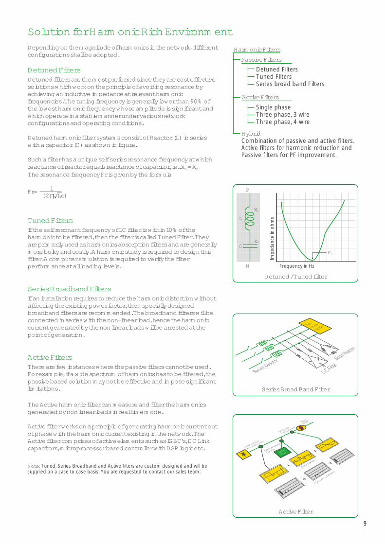
Depending on the magnitude of harmonics in the network, different configurations shall be adopted.
Detuned filters are the most preferred since they are cost effective solutions which work on the principle of avoiding resonance by achieving an inductive impedance at relevant harmonic frequencies. The tuning frequency is generally lower than 90% of the lowest harmonic frequency whose amplitude is significant and which operate in a stable manner under various network configurations and operating conditions.
Detuned harmonic filter systems consist of Reactor (L) in series with a capacitor (C) as shown in figure.
Such a filter has a unique self series resonance frequency at which reactance of reactor equals reactance of capacitor, ie.. X = XL C.
The resonance frequency Fr is given by the formula
If the self resonant frequency of LC filter is within 10% of the harmonic to be filtered, then the filter is called Tuned Filter. They are primarily used as harmonics absorption filters and are generally more bulky and costly. A harmonic study is required to design this filter. A computer simulation is required to verify the filter performance at all loading levels.
If an installation requires to reduce the harmonic distortion without affecting the existing power factor, then specially designed broadband filters are recommended. The broadband filters will be connected in series with the non-linear load, hence the harmonic current generated by the non linear loads will be arrested at the point of generation.
There are few instances where the passive filters cannot be used. For example, if a wide spectrum of harmonics has to be filtered, the passive based solution may not be effective and impose significant limitations.
The Active harmonic filter can measure and filter the harmonics generated by non linear loads in real time mode.
Active filter works on a principle of generating harmonic current out of phase with the harmonic current existing in the network. The Active filter comprises of active elements such as IGBT’s, DC Link capacitors, microprocessor based controller with DSP logic etc.
Note: Tuned, Series Broadband and Active filters are custom designed and will be supplied on a case to case basis. You are requested to contact our sales team.
Detuned Filters
Tuned Filters
Series Broadband Filters
Active Filters
Solution for Harmonic Rich Environment
Fr= 1( 2 ∏ Lc)
Harmonic Filters
Series broad band Filters
Detuned FiltersTuned Filters
Single phaseThree phase, 3 wireThree phase, 4 wire
Hybrid
Active Filters
Passive Filters
Combination of passive and active filters.Active filters for harmonic reduction and Passive filters for PF improvement.
P
N
XL
XC
Impe
danc
e in
ohm
sFrequency in Hz
Fr
L
C
Detuned / Tuned filter
Series Broad Band Filter
Active Filter
9
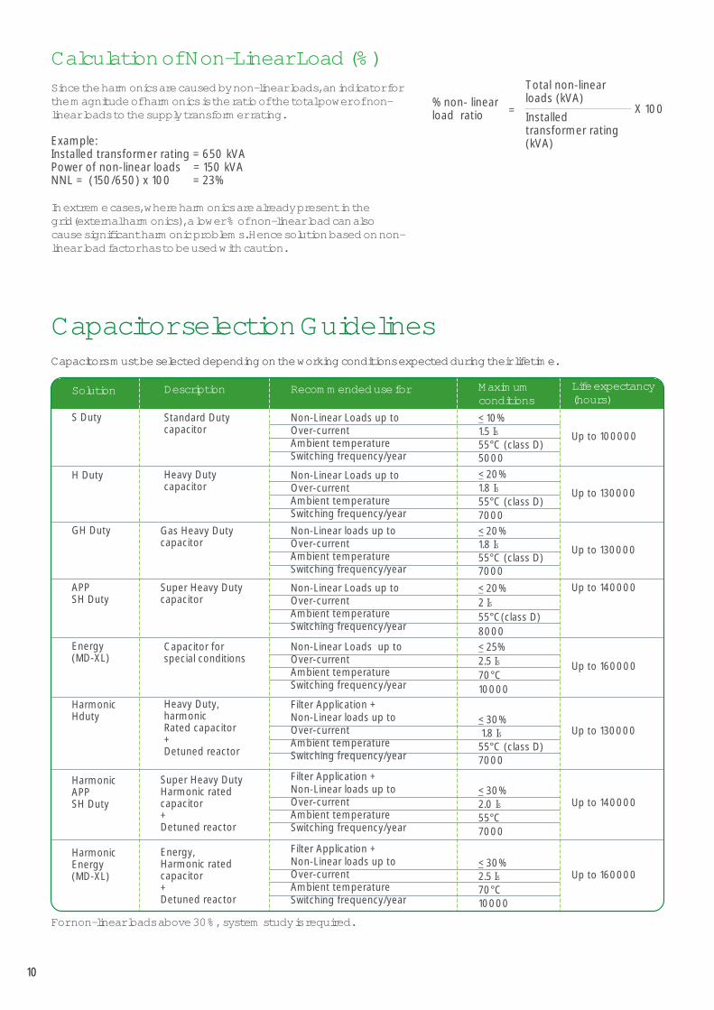
Capacitors must be selected depending on the working conditions expected during their lifetime.
Non-Linear Loads up to Over-currentAmbient temperatureSwitching frequency/year
Recommended use for
Non-Linear Loads up toOver-current
temperatureSwitching frequency/yearAmbient
Non-Linear Loads up toOver-currentAmbient temperatureSwitching frequency/year
Filter Application +Non-Linear loads up to Over-currentAmbient temperatureSwitching frequency/year
Standard Duty capacitor
Description
Heavy Duty capacitor
Capacitor for special conditions
Heavy Duty,harmonic Rated capacitor+ Detuned reactor
Super Heavy DutyHarmonic rated capacitor+ Detuned reactor
S Duty
Solution
Energy(MD-XL)
H Duty
Harmonic Hduty
Harmonic
APP SH Duty
Up to 100000
Life expectancy(hours)
Up to 140000
Up to 160000
Up to 130000
Maximum conditions< 10%1.5 S I55°C (class D)5000< 20%1.8 S I55°C (class D)7000
< 25%2.5 IS70°C10000
Filter Application +Non-Linear loads up to Over-currentAmbient temperatureSwitching frequency/year
Up to 130000< 30% 1.8 IS55°C (class D)7000
< 30%2.0 IS55°C7000
Non-Linear loads up toOver-currentAmbient temperatureSwitching frequency/year
Non-Linear Loads up toOver-currentAmbient temperatureSwitching frequency/year
Gas Heavy Dutycapacitor
Super Heavy Duty capacitor
GH Duty
APPSH Duty
Up to 140000
Up to 130000
< 20%1.8 IS55°C (class D)7000< 20%2 IS55°C(class D)8000
Filter Application +Non-Linear loads up to Over-currentAmbient temperatureSwitching frequency/year
Energy, Harmonic rated capacitor+ Detuned reactor
Harmonic Energy(MD-XL) Up to 160000
< 30%2.5 IS70°C10000
For above 30%, non-linear loads system study is required.
Capacitor selection Guidelines
Since the harmonics are caused by non-linear loads, an indicator for the magnitude of harmonics is the ratio of the total power of non-linear loads to the supply transformer rating.
Example: Installed transformer rating = 650 kVAPower of non-linear loads = 150 kVANNL = (150/650) x 100 = 23%
In extreme cases, where harmonics are already present in the grid(external harmonics), a lower % of non-linear load can also cause significant harmonic problems. Hence solution based on non-linear load factor has to be used with caution.
Calculation of Non-Linear Load (%)
% non- linear =load ratio
Total non-linear loads (kVA)
Installed transformer rating (kVA)
X 100
10

Rated voltage and currentCapacitors must be designed and selected according to the service voltage of the network (US) on which they will operate, taking account of voltage fluctuations, including long duration operating at a supply voltage up to (1.1 x US).
According to IEC 60681-1 standard, the rated voltage (UN) of a capacitor is defined as the continuously admissible operating voltage.
The rated current (IN) of a capacitor is the current flowing through the capacitor when the rated voltage (UN) is applied at its terminals, supposing a purely sinusoidal voltage and the exact value of reactive power (kvar) generated. Capacitor units shall be suitable for continuous operation at an r.m.s. current of (1.3 x IN). The service current (IS) of a capacitor is defined here as the current flowing through the capacitor when the service voltage (US) is applied at its terminals, supposing a purely sinusoidal voltage and the exact value of reactive power (kvar) generated.
In order to operate safely in real conditions, the rated voltage (UN) of capacitors must be higher than the service voltage (US) of the network on which they will operate.
Standard DutyHeavy DutyEnergyHarmonic Heavy DutyHarmonic Energy
Network servicevoltage (U )S
50 Hz230
250260
400
440460460500500
440
480500500530580
The following table gives the design rated voltage (UN), as defined per IEC 61831-1, suitable for different network service voltages, for the different construction technologies.
Life expectancy is given considering standard operating conditions: service voltage (US), service current (IS), 25°C ambient temperature.
CAUTION: The life expectancy will be reduced if capacitors are used exceeding the maximum level of conditions indicated in the selection table.
11
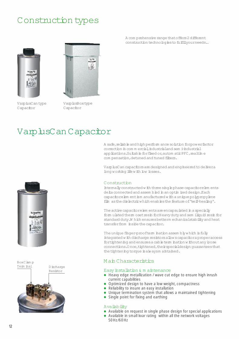
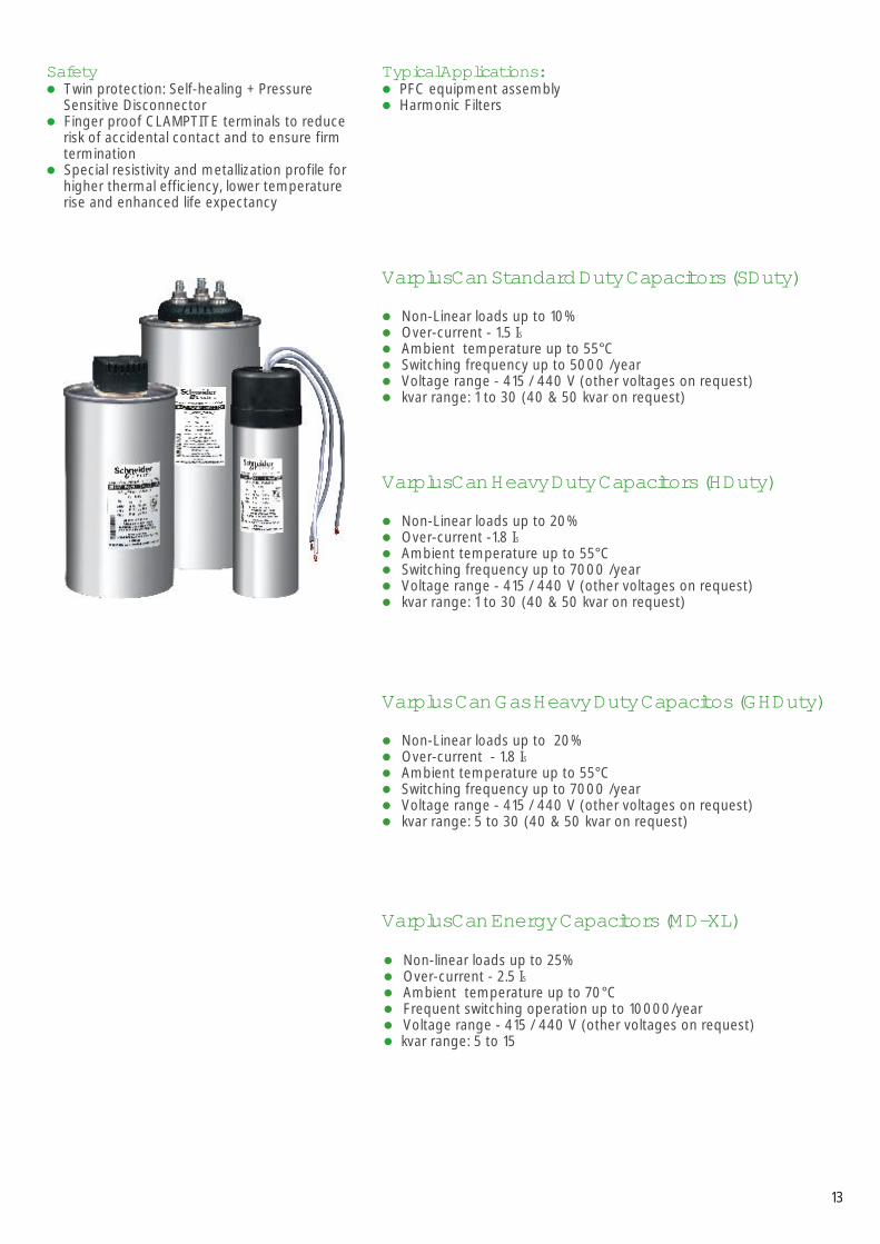
VarplusCan CapacitorA safe, reliable and high performance solution for power factor correction in commercial, industrial and semi-industrial applications. Suitable for fixed or, automatic PFC, real time compensation, detuned and tuned filters.
VarplusCan capacitors are designed and engineered to deliver a long working life with low losses.
ConstructionInternally constructed with three single phase capacitor elements delta connected and assembled in an optimized design. Each capacitor element is manufactured with a unique polypropylene film as the dielectric which enables the feature of “self-healing".
The active capacitor elements are encapsulated in a specially formulated thermoset resin for Heavy duty and semi liquid resin for standard duty. Which ensures better mechanical stability and heat transfer from inside the capacitor.
The unique finger-proof termination assembly which is fully integrated with discharge resistors allows capacitor a proper access for tightening and ensures a cable termination without any loose connections. Once, tightened, their special design guarantees that the tightening torque is always maintained.
Easy installation & maintenancel
l
l
l
l
l
l
Heavy edge metallization / wave cut edge to ensure high inrush current capabilitiesOptimized design to have a low weight, compactness Reliability to insure an easy installation Unique termination system that allows a maintained tightening Single point for fixing and earthing
Available on request in single phase design for special applications Available in small kvar rating within all the network voltages 50Hz/60Hz
Availability
Box Clamp Terminal Discharge
Resistor
Construction types
A comprehensive range that offers 2 different construction technologies to fulfill your needs.…
VarplusBox typeCapacitor
VarplusCan typeCapacitor
12
Main Characteristics
l
l
l
l
l
Non-linear loads up to 25%Over-current - Ambient temperature up to 70°CFrequent switching operation up to 10000/year
2.5 IS
Voltage range - 415 / 440 V (other voltages on request)kvar range: 5 to 15l
VarplusCan Energy Capacitors (MD-XL)
VarplusCan Standard Duty Capacitors (SDuty)
l
l
l
l
l
l
Non-Linear loads up to 10%
(other voltages on request)kvar range: 1 to 30 (
Over-current - 1.5 ISAmbient temperature up to 55°CSwitching frequency up to 5000 /yearVoltage range - 415 / 440 V
40 & 50 kvar on request)
VarplusCan Heavy Duty Capacitors (HDuty)
l
l
l
l
l
l
Non-Linear loads up to 20%Over-current -1.8 ISAmbient temperature up to 55°CSwitching frequency up to 7000 /yearVoltage range - 415 / 440 V (other voltages on request)kvar range: 1 to 30 (40 & 50 kvar on request)
Varplus Can Gas Heavy Duty Capacitos (GHDuty)
l
l
l
l
l
l
Non-Linear loads up to 20%Over-current - 1.8 Ambient temperature up to 55°CSwitching frequency up to 7000 /year
IS
Voltage range - 415 / 440 V (other voltages on request)kvar range: 5 to 30 (40 & 50 kvar on request)
Typical Applications:l
l
PFC equipment assemblyHarmonic Filters
Safetyl
l
l
Twin protection: Self-healing + Pressure Sensitive Disconnector Finger proof CLAMPTITE terminals to reduce risk of accidental contact and to ensure firm terminationSpecial resistivity and metallization profile for higher thermal efficiency, lower temperature rise and enhanced life expectancy
13
Rated VoltageFrequency Power rangeLosses(Dielectrical)Losses (Total)Peak inrush currentOver voltageOver currentMean life expectancyCapacitance toleranceVoltage testBetween terminalsBetween earth & terminals Discharge resistorsSafetyProtectionCasingDielectric
Impregnation
Ambient temperatureHumidityAltitude
Mounting
Connection
Standards IS 13340-1993/IS13341-1992, IEC 60831-1/-2
VarplusCan Standard Duty Capacitors (SDuty)
VarplusCan Heavy Duty Capacitors (HDuty)
VarplusCan Gas Heavy DutyCapacitors (GH Duty)
VarplusCan Energy (MD-XL)
415 /440V (other voltage on request)
50 Hz
1 to 30 kvar (other kvar on request) 5 to 15 kvar < 0,2 watt/kvar < 0,5 watt/kvar < 0,45 watt/kvar
1.1 U continuousS
Up to 200 x IN Up to 250 x IN Up to 250 x IN Up to 350 x IN
1.5 x I S 1.8 x I S 1.8 x I S 2.5 x I S
Up to 160,000 HrsUp to 130,000 HrsUp to 130,000 HrsUp to 100,000 Hrs-5%, +10%
2.15x U (AC), 2 secN
< 660V, 3000V (AC) 10 sec & >660V, 6000V (AC), 10sec
Fitted: standard discharge time 60 secondsSelf healing + pressure sensitive disconnector + discharge deviceIP30 (IP54 on request)Extruded aluminum can
Metallized Polypropylene film with Zn/Al alloy
Metallized Polypropylene film with Zn/Al alloy, special resistivity & profile, special edge (wave cut)
Double metallized paper + Polypropylene film
Metallized Polypropylene film with Zn/Al alloy, special resistivity & profile, special edge (wave cut)
Non - PCB, Bio degradable resin
Non - PCB, Dry resinBio-
degradable Inert gas impregnated, Bio-degradable Dry resin
Non-PCB, oil
Environmental conditions
-25 / + 55°C (Class D) °C -25 / +70°C°C
95%4000 m above sea level
Installation featuresIndoor, vertical position
Indoor, any position
Indoor, any position
Indoor, vertical position
Three phase delta connection (Single phase on request)Threaded M12 stud at bottomFixing and earthing
Terminals CLAMPTITE - Three phase terminal with electric shock protection (finger proof), designed for up to 16sq.mm cable termination, Double fast-on with cable ( <4kVAr)
5 to 30 kvar
Technical Details
14
US = Service voltageUN = Rated voltageIS = Service currentIN = Rated current
Rated KVAr
Rated Current(Amps)
Rated capacitanceµF (x 3)
Dimension (mm)Dia Height
Net Weight (kg)
Ordering reference no
Reference Drawing no.
1 1.3 5.5 63 90 0.4 MEH_VCSDY_010A44_3 Drawing A2 2.6 11 63 115 0.5 MEH_VCSDY_020A44_33 3.9 16.4 50 195 0.5 MEH_VCSDY_030A44_34 5.2 21.9 50 195 0.6 MEH_VCSDY_040A44_35 6.6 33 50 195 0.7 MEH_VCSDY_050A44_37.5 9.8 50 63 195 0.9 MEH_VCSDY_075A44_310 13.1 55 70 195 1.0 MEH_VCSDY_100A44_312.5 12.5 69 75 278 1.2 MEH_VCSDY_125A44_315 19.7 82 75 278 1.3 MEH_VCSDY_150A44_320 26.2 110 90 278 2.1 MEH_VCSDY_200A44_325 32.8 137 90 278 2.2 MEH_VCSDY_250A44_330 39.4 164 90 278 2.3 MEH_VCSDY_300A44_340 52.4 220 116 278 3.8 MEH_VCSDY_400A44_3
Drawing B
Drawing C
Drawing E50 65.6 274 136 278 4.9 MEH_VCSDY_500A44_3
VarplusCan Standard Duty Capacitors (SDuty)
1 1.3 5.5 63 90 0.5 MEH_VCHDY_010A44_3 Drawing A 2 2.6 11 50 195 0.6 MEH_VCHDY_020A44_33 3.9 16.4 50 195 0.6 MEH_VCHDY_030A44_34 5.2 21.9 50 195 0.7 MEH_VCHDY_040A44_35 6.6 33 63 195 0.8 MEH_VCHDY_050A44_37.5 9.8 50 63 195 1 MEH_VCHDY_075A44_310 13.1 55 75 203 1.1 MEH_VCHDY_100A44_3 Drawing B 12.5 12.5 69 90 212 1.5 MEH_VCHDY_125A44_3 Drawing C15 19.7 82 90 212 1.6 MEH_VCHDY_150A44_320 26.2 110 116 212 2.4 MEH_VCHDY_200A44_3 Drawing D25 32.8 137 116 212 2.5 MEH_VCHDY_250A44_330 39.4 164 136 212 3.1 MEH_VCHDY_300A44_340 52.4 220 136 278 3.4 MEH_VCHDY_400A44_3 Drawing E 50 65.6 274 136 278 4.6 MEH_VCHDY_500A44_3
VarplusCan Heavy Duty capacitors (HDuty)
5 6.6 33 63 195 0.9 MEH_VCGSF_050A44_3 Drawing A 7.5 9.8 50 63 195 1 MEH_VCGSF_075A44_310 13.1 55 75 203 1.1 MEH_VCGSF_100A44_3 Drawing B 12.5 12.5 69 90 212 1.5 MEH_VCGSF_125A44_3 Drawing C 15 19.7 82 90 212 1.6 MEH_VCGSF_150A44_320 26.2 110 116 212 2.4 MEH_VCGSF_200A44_3 Drawing D25 32.8 137 116 212 2.5 MEH_VCGSF_250A44_330 39.4 164 136 212 3.1 MEH_VCGSF_300A44_340 52.4 220 136 278 3.4 MEH_VCGSF_400A44_3 Drawing E 50 65.6 274 136 278 4.6 MEH_VCGSF_500A44_3
Varplus Can Gas Heavy Duty capacitor (GH Duty)
5 6.6 33 75 203 1.2 MEH_VCENY_050A44_3 Drawing B7.5 9.8 50 90 212 1.4 MEH_VCENY_075A44_310 13.1 55 90 278 2.3 MEH_VCENY_100A44_3 Drawing C 12.5 12.5 69 90 278 2.6 MEH_VCENY_125A44_315 19.7 82 116 278 3.3 MEH_VCENY_150A44_3 Drawing D
VarplusCan Energy (MD-XL)
Note: 40 & 50 kVAr on request
Note: 40 & 50 kvar on request
Note: 40 & 50 kVAr on request
440V Capacitor ordering reference nos.
15
Refer Drawings in page no. 31
VarplusBox Capacitor
Varplus Box capacitors deliver reliable performance in most of the fixed applications such as Fixed & Automatic PFC systems and in networks with frequently switched loads & harmonic disturbances.
The design is specially adapted for mechanical stability. The enclosure is designed to ensure reliable operation of the capacitors in hot and humid conditions, without any additional ventilation louvers.
Heavy edge metallization / wave cut edge to ensure high inrush current capabilitiesSpecial resistivity and profile metallization for enhanced life
It’s unique safety feature PSD, electrically disconnects the capacitors safely at the end of their life.
Easily mountable inside panels or in a stand- alone configurationSuitable for flexible bank configuration
Pre coated Metal box Higher ratings up to 100kvarEasy repair and maintenance
Stand alone PFC equipmentFixed bankDirect connection to a machine, in hostile environment conditions
Construction
Main Characteristics / High performance
Safety
Flexibility
Additional Features
Typical Applications
l
l
l
l
l
l
l
l
l
l
l
16
Varplus Box Energy Capacitors (MD-XL)
l
l
l
l
l
Non-linear loads up to 25%Over-current - Ambient temperature up to 70°CFrequent switching operation up to 10000/year
2.5 IS
Voltage range - 415 / 440 V (other voltages on request)kvar range: 5 to 100 (40, 50, 75 and 100 kvar on request)l
Varplus Box Heavy Duty Capacitors (HDuty)
l
l
l
l
l
l
Non-Linear loads up to 20%Over-current -1.8 ISAmbient temperature up to 55°CSwitching frequency up to 7000 /yearVoltage range - 415 / 440 V (other voltages on request)kvar range: 5 to 100 (40, 50, 75 and 100 kvar on request)
Varplus Box APP Super Heavy Duty Capacitors (SHDuty)
l
l
l
l
l
Non-linear loads up to 20%Over-current - Ambient temperature up to 70°CFrequent switching operation up to 10000/year
2.0 IS
Voltage range - 415 / 440 V (other voltages on request)kvar range: 5 to 100 (40, 50, 75 and 100 kvar on request)
l
VarplusBox Standard Duty Capacitors (SDuty)
l
l
l
l
l
l
Non-Linear loads up to 10%Over-current - 1.5 ISAmbient temperature up to 55°CSwitching frequency up to 5000 /yearVoltage range - 415 / 440 V (other voltage on request)kvar range: 1 to 100 (40, 50, 75 and 100 kvar on request)
17
Rated VoltageFrequency Power rangeLosses(Dielectrical)Losses (Total)Peak inrush currentOver voltageOver currentMean life expectancyCapacitance toleranceVoltage testBetween terminalsBetween earth & terminals Discharge resistorsSafetyProtectionCasingDielectric
Impregnation
Standards 13340-1993, IS 13341-1992, IEC 60831-1/-2
VarplusBox Standard DutyCapacitors (SDuty)
VarplusBox Heavy DutyCapacitors (HDuty)
Varplus BoxEnergyCapacitors (MD-XL)
Varplus Box APP Super Heavy DutyCapacitors (SHDuty)
IS 13585-1994,IEC 60834-1/-2
IS 13340-1993, IS 13341-1992, IEC 60831-1/-2
IS 13340-1993, IS 13341-1992, IEC 60831-1/-2
415 /440V (other voltage on request)
50 Hz
From 1 to 100 kvar From 5 to 100 kvarFrom 5 to 100 kvar From 5 to 100 kvar
Ambient temperatureHumidityAltitude
MountingConnectionFixing and earthingTerminals
< 0,2 watt/kvar < 0,5 watt/kvar
1.1 U continuous S
Up to 150 x IN Up to 250 x IN Up to 400 x IN Up to 350 x IN
1.5 x IS 1.8 x IS 2.5 x IS 2.0 x ISUp to 140,000 HoursUp to 160,000 HoursUp to 130,000 HoursUp to 100,000 Hours
-5%, +10%
2.15x UN (AC), 2 sec
< 660V, 3000V (AC) 10 sec & >660V, 6000V (AC), 10sec
Fitted: standard discharge time 60 secondsSelf healing + pressure sensitive disconnector for every phase + discharge deviceIP20 (IP54 on request)Sheet steel enclosure
Metallised Polypropylene film
Zn/Al alloy, flatmetallization with
Double metallized paper + Polypropylene film
Aluminum foil +PP film
Metallised Polypropylene film with Zn/Al alloy, special resistivity & profile, special edge (wave cut)
Non - PCB, Bio- degradable PUR resin
Non - PCB,Dry ResinBio-degradable
Non-PCB, oil Non-PCB, oil
Environmental conditions
-25 +55°C (Class D)°C /
95%4000m above sea level
Installation featuresIndoor, vertical positionThree phase (delta connection)
Mounting cleatsBushing terminals designed for large cable termination and direct bus bar mounting for banking
-25 +55°C (Class D) °C /-25 +70°C (Class D) °C /
Technical Details
18
Rated KVAr
Rated Current(Amps)
Rated capacitanceµF (x 3)
Dimension (mm)W1 W2 D H
Net Weight (kg)
Ordering reference no.
Reference Drawing nos.
1 1.3 7 115 95 55 117 0.55 MEH_VBSDY_010A44_3 Drawing 10 2 2.6 13 115 95 55 148 0.65 MEH_VBSDY_020A44_33 3.9 20 144 125 55 121 0.75 MEH_VBSDY_030A44_34 5.2 27 144 55 152 0.95 MEH_VBSDY_040A44_35 6.6 33 144 55 152 0.95 MEH_VBSDY_050A44_36 7.9 40 144 55 162 1.1 MEH_VBSDY_060A44_37.5 10 50 263 243 97 260 3 MEH_VBSDY_075A44_3 Drawing 110 13 55 263 97 260 3.5 MEH_VBSDY_100A44_312.5 16 69 263 97 260 3.6 MEH_VBSDY_125A44_315 20 82 263 97 355 4.7 MEH_VBSDY_150A44_320 26 110 263 97 355 4.8 MEH_VBSDY_200A44_325 33 137 263 97 355 5.1 MEH_VBSDY_250A44_330 39 164 309 289 153 455 7.7 MEH_VBSDY_300A44_3 40 52 219 309 153 455 7.8 MEH_VBSDY_400A44_350 66 274 309 153 455 8 MEH_VBSDY_500A44_375 98 411 435 280 270 455 21.3 MEH_VBSDY_750A44_3 Drawing 4100 131 548 545 390 270 455 27 MEH_VBSDY_X00A44_3 Drawing 5
125125125
243243243243243
289289
VarplusBox Standard Duty Capacitors (SDuty)
5 6.6 33 263 243 97 260 0.95 MEH_VBHDY_050A44_3 Drawing 1 7.5 10 50 263 243 97 260 3 MEH_VBHDY_075A44_310 13 55 263 243 97 355 3.5 MEH_VBHDY_100A44_312.5 16 69 263 243 97 355 3.6 MEH_VBHDY_125A44_315 20 82 263 243 97 355 4.7 MEH_VBHDY_150A44_320 26 110 309 289 153 355 4.8 MEH_VBHDY_200A44_325 33 137 309 289 153 355 5.1 MEH_VBHDY_250A44_330 39 164 309 289 224 497 7.7 MEH_VBHDY_300A44_3 Drawing 240 52 219 309 289 224 497 7.8 MEH_VBHDY_400A44_350 66 274 309 289 224 497 8 MEH_VBHDY_500A44_375 98 411 625 460 315 455 21.3 MEH_VBHDY_750A44_3 Drawing 4100 131 548 795 630 315 455 27 MEH_VBHDY_X00A44_3 Drawing 5
Varplus Box Heavy Duty Capacitors (HDuty)
5 6.6 33 263 243 97 260 3.5 MEH_VBENY_050A44_3 Drawing 17.5 10 50 263 243 97 355 4.7 MEH_VBENY_075A44_310 13 55 263 243 97 355 5 MEH_VBENY_100A44_312.5 16 69 263 243 97 355 5.4 MEH_VBENY_125A44_315 20 82 309 289 153 355 8 MEH_VBENY_150A44_320 26 110 309 289 153 355 8.7 MEH_VBENY_200A44_325 33 137 309 289 153 355 9.4 MEH_VBENY_250A44_330 39 164 309 289 224 497 11.3 MEH_VBENY_300A44_3 Drawing 2 40 52 219 309 289 224 497 12.2 MEH_VBENY_400A44_350 66 274 309 289 224 497 13 MEH_VBENY_500A44_375 98 411 625 460 315 455 38 MEH_VBENY_750A44_3 Drawing 4 100 131 548 795 630 315 455 50 MEH_VBENY_X00A44_3 Drawing 5
Varplus Box Energy Capacitors (MD-XL)
5 6.6 33 260 250 123 165 5.3 MEH_VBAPP_050A44_3 Drawing 11 7.5 10 50 260 250 123 185 6.4 MEH_VBAPP_075A44_310 13 55 260 250 123 210 7.4 MEH_VBAPP_100A44_312.5 16 69 260 250 123 230 8.6 MEH_VBAPP_125A44_315 20 82 260 250 123 250 9.6 MEH_VBAPP_150A44_320 26 110 383 370 123 250 13.8 MEH_VBAPP_200A44_325 33 137 383 370 123 277 15.8 MEH_VBAPP_250A44_330 39 164 405 263 383 367 28.6 MEH_VBAPP_300A44_3 Drawing 12 40 52 219 405 230 383 367 37 MEH_VBAPP_400A44_350 66 274 405 230 383 395 42 MEH_VBAPP_500A44_375 98 411 560 385 383 395 59 MEH_VBAPP_750A44_3 Drawing 13 100 131 548 715 540 383 395 77.2 MEH_VBAPP_X00A44_3 Drawing 14
Varplus Box APP Super Heavy Duty Capacitors (SHDuty)
440V Capacitor ordering reference nos.
19
Refer Drawings in page no. 32 and 33. Drawing 11 & 12 on request.
Harmonic Capacitors for Detuned Filter application
Reactors have to be associated to capacitor banks for Power Factor Correction in systems with significant non-linear loads generating harmonics.
Capacitors and reactors are configured in a series resonant circuit, tuned so that the series resonant frequency is below the lowest harmonic frequency present in the system. This configuration is called "Detuned Capacitor Bank", and the reactors referred as "Detuned Reactors".
The tuning frequency can be expressed by the relative impedance of the reactor (in %), or by the tuning order, or directly in Hz.
The most common values of relative impedance are 5.67%, 7% and 14% (14% is used with high level of 3rd harmonic voltages).
Presence of zero-sequence harmonics (3, 9, …)Need for reduction of the harmonic distortion levelOptimization of the capacitor and reactor componentsFrequency of ripple control system if any*
*To prevent disturbances of the remote control installation, the tuning frequency has to be selected at a lower value than the ripple control frequency.
In the Detuned filter application the voltage across the capacitors is higher than the nominal system voltage.
Therefore capacitors have been designed to withstand higher voltages. The table provides the details of Capacitor voltage applicable for different tuning factors:
The use of Detuned reactors prevents harmonic resonance problems, avoids the risk of overloading capacitors and leads to reduction in voltage harmonic distortion in the network.
The selection of the tuning frequency of the reactor capacitor depends on multiple factors:
And also the presence of series reactor will increase the voltage across the capacitor due to Ferranti effect.
l
l
l
l
Tuning Factor P (%)
Tuning order (Fh/F1)
Tuning frequency @50Hz (Hz)
5.67 4.2 2107 3.8 18914 2.67 134
5.67 440 4807 440 48014 440 525
Tuning Factor P (%)
Bus Voltage
Minimum Capacitor Voltage
20
VarplusCan Harmonic CapacitorsHarmonic capacitor is specifically designed to carry wide spectrum of harmonic and fundamental currents without overloading
It is designed for higher voltage capacitor to allow increased voltage due to introduction of series reactor
The kvar of the capacitor is suitably designed to deliver the rated kvar of the filter at the bus voltage.
VarplusCan Harmonic Heavy Duty CapacitorsFor use with detuned reactor
l
l
Non-Linear loads upto 30%Switching frequency up to 7000 /year
VarplusCan Harmonic Gas Heavy Duty CapacitorsFor use with detuned reactor
l
l
Non-Linear loads upto 30%Switching frequency up to 7000 /year
Varplus Can Harmonic Energy CapacitorsFor use with detuned reactorl
l
Non-Linear loads upto 30%Switching frequency up to 10000 /year
Net work Voltage
440V 5.67% 5 63 195 MEH_VCHH1_050A44_3 17.5 70 195 MEH_VCHH1_075A44_3 110 75 203 MEH_VCHH1_100A44_3 112.5 90 212 MEH_VCHH1_125A44_3 115 90 212 MEH_VCHH1_150A44_3 120 116 212 MEH_VCHH1_200A44_3 125 136 212 MEH_VCHH1_250A44_3 150 136 212 MEH_VCHH1_250A44_3 275 136 212 MEH_VCHH1_250A44_3 3100 136 212 MEH_VCHH1_250A44_3 4
440V 7% 5 63 195 MEH_VCHH1_050A44_3 17.5 70 195 MEH_VCHH1_075A44_3 110 75 203 MEH_VCHH1_100A44_3 112.5 90 212 MEH_VCHGH1_125A44_3 115 90 212 MEH_VCHH1_150A44_3 120 116 212 MEH_VCHH1_200A44_3 125 136 212 MEH_VCHH1_250A44_3 150 136 212 MEH_VCHH1_250A44_3 275 136 212 MEH_VCHH1_250A44_3 3100 136 212 MEH_VCHH1_250A44_3 4
440V 14% 5 63 195 MEH_VCHH2_050A44_3 17.5 70 195 MEH_VCHH2_075A44_3 110 90 212 MEH_VCHH2_100A44_3 112.5 90 212 MEH_VCHH2_125A44_3 115 116 212 MEH_VCHH2_150A44_3 120 116 212 MEH_VCHH2_200A44_3 125 136 212 MEH_VCHH2_250A44_3 150 136 212 MEH_VCHH2_250A44_3 275 136 212 MEH_VCHH2_250A44_3 3100 136 212 MEH_VCHH2_250A44_3 4
Drawing A
Drawing BDrawing C
Drawing D
Drawing A
Drawing BDrawing C
Drawing D
Drawing A
Drawing C
Drawing D
Detuning Factor (%)
Rated kvar@ 440V
Harmonic Capacitor ordering reference No.
Capacitor Dimension (mm)D H
Reference Drawing Nos.
CapQty.
VarplusCan Harmonic Heavy Duty Capacitors (H Duty)Harmonic Capacitor ordering reference nos.
21Refer Drawings in page no. 31
VarplusCan Harmonic Gas Heavy Duty Capacitors (GH Duty)
440V 5.67% 5 63 195 MEH_VCGH1_050A44_3 1 Drawing A7.5 70 195 MEH_VCGH1_075A44_3 110 75 203 MEH_VCGH1_100A44_3 112.5 90 212 MEH_VCGH1_125A44_3 115 90 212 MEH_VCGH1_150A44_3 120 116 212 MEH_VCGH1_200A44_3 125 136 212 MEH_VCGH1_250A44_3 150 136 212 MEH_VCGH1_250A44_3 275 136 212 MEH_VCGH1_250A44_3 3100 136 212 MEH_VCGH1_250A44_3 4
440V 7% 5 63 195 MEH_VCGH1_050A44_3 17.5 70 195 MEH_VCGH1_075A44_3 110 75 203 MEH_VCGH1_100A44_3 112.5 90 212 MEH_VCGH1_125A44_3 115 90 212 MEH_VCGH1_150A44_3 120 116 212 MEH_VCGH1_200A44_3 125 136 212 MEH_VCGH1_250A44_3 150 136 212 MEH_VCGH1_250A44_3 275 136 212 MEH_VCGH1_250A44_3 3100 136 212 MEH_VCGH1_250A44_3 4
440V 14% 5 63 195 MEH_VCGH2_050A44_3 17.5 70 195 MEH_VCGH2_075A44_3 110 90 212 MEH_VCGH2_100A44_3 112.5 90 212 MEH_VCGH2_125A44_3 115 116 212 MEH_VCGH2_150A44_3 120 116 212 MEH_VCGH2_200A44_3 125 136 212 MEH_VCGH2_250A44_3 150 136 212 MEH_VCGH2_250A44_3 275 136 212 MEH_VCGH2_250A44_3 3100 136 212 MEH_VCGH2_250A44_3 4
Drawing BDrawing C
Drawing D
Drawing A
Drawing BDrawing C
Drawing D
Drawing A
Drawing C
Drawing D
Net work Voltage
Detuning Factor (%)
Rated kvar@ 440V
Harmonic Capacitor ordering reference No.
Capacitor DimensionD H
Reference Drawing Nos.
CapQty.
Varplus Can Harmonic Energy Capacitor (MD-XL)
440V 5.67% 5 75 203 MEH_VCEH1_050A44_3 Drawing B7.5 75 278 MEH_VCEH1_075A44_310 90 278 MEH_VCEH1_100A44_312.5 90 278 MEH_VCEH1_125A44_315 116 278 MEH_VCEH1_150A44_3
440V 7% 5 75 203 MEH_VCEH1_050A44_37.5 75 278 MEH_VCEH1_075A44_310 90 278 MEH_VCEH1_100A44_312.5 90 278 MEH_VCEH1_125A44_315 116 278 MEH_VCEH1_150A44_3
440V 14% 5 75 278 MEH_VCEH2_050A44_37.5 75 278 MEH_VCEH2_075A44_310 90 278 MEH_VCEH2_100A44_312.5 116 278 MEH_VCEH2_125A44_315 116 278 MEH_VCEH2_150A44_3
Drawing C
Drawing DDrawing B
Drawing C
Drawing DDrawing C
Drawing D
Net work Voltage
Detuning Factor (%)
Rated kvar@ 440V
Harmonic Capacitor ordering reference No.
Capacitor DimensionD H
Reference Drawing Nos.
22
Note: H1 = Rated voltage 480H2 = Rated voltage 525
Refer Drawings in page no. 31
VarplusBox Harmonic Capacitors
VarplusBox Harmonic Heavy Duty CapacitorsFor use with detuned reactorl
l
Non-Linear loads upto 30%Switching frequency up to 7000 /year
Varplus Box Harmonic Energy Capacitors For use with detuned reactorl
l
Non-Linear loads upto 30%Switching frequency up to 10000 /year
VarplusBox Harmonic APP Super Heavy Duty CapacitorFor use with detuned reactor
l
l
Non-Linear loads upto 30%Switching frequency up to 8000 /year
Varplus Box Harmonic Heavy Duty Capacitors (HDuty)Net work Voltage
440V 5.67% 5 263 243 97 260 MEH_VBHH1_050A44_3 1 Drawing 17.5 263 243 97 355 MEH_VBHH1_075A44_3 110 263 243 97 355 MEH_VBHH1_100A44_3 112.5 263 243 97 355 MEH_VBHH1_125A44_3 115 309 289 153 355 MEH_VBHH1_150A44_3 120 309 289 153 355 MEH_VBHH1_200A44_3 125 309 289 153 355 MEH_VBHH1_250A44_3 150 309 289 153 355 MEH_VBHH1_250A44_3 275 309 289 153 355 MEH_VBHH1_250A44_3 3100 309 289 153 355 MEH_VBHH1_250A44_3 4
440V 7% 5 263 243 97 260 MEH_VBHH1_050A44_3 17.5 263 243 97 355 MEH_VBHH1_075A44_3 110 263 243 97 355 MEH_VBHH1_100A44_3 112.5 263 243 97 355 MEH_VBHH1_125A44_3 115 309 289 153 355 MEH_VBHH1_150A44_3 120 309 289 153 355 MEH_VBHH1_200A44_3 125 309 289 153 355 MEH_VBHH1_250A44_3 150 309 289 153 355 MEH_VBHH1_250A44_3 275 309 289 153 355 MEH_VBHH1_250A44_3 3100 309 289 153 355 MEH_VBHH1_250A44_3 4
440V 14% 5 263 243 97 260 MEH_VBHH2_050A44_3 17.5 263 243 97 355 MEH_VBHH2_075A44_3 110 263 243 97 355 MEH_VBHH2_100A44_3 112.5 309 289 97 355 MEH_VBHH2_125A44_3 115 309 289 153 355 MEH_VBHH2_150A44_3 120 309 289 153 355 MEH_VBHH2_200A44_3 125 309 289 153 355 MEH_VBHH2_250A44_3 150 309 289 224 497 MEH_VBHH2_250A44_3 275 309 289 153 355 MEH_VBHH2_250A44_3 3100 309 289 153 355 MEH_VBHH2_250A44_3 4
Detuning Factor (%)
Rated kvar@ 440V
Harmonic Capacitor ordering reference No.
Capacitor Dimension (mm)W1 W2 D H
Reference Drawing Nos.
CapQty
Harmonic Capacitor ordering reference nos.
23Refer Drawings in page no. 32
Varplus Box Harmonic Energy Capacitors (MD-XL)Net work Voltage
440V 5.67% 5 263 243 97 260 MEH_VBEH1_050A44_3 1 Drawing 17.5 263 243 97 355 MEH_VBEH1_075A44_3 110 263 243 97 355 MEH_VBEH1_100A44_3 112.5 263 243 97 355 MEH_VBEH1_125A44_3 115 309 289 153 355 MEH_VBEH1_150A44_3 120 309 289 153 355 MEH_VBEH1_200A44_3 125 309 289 153 355 MEH_VBEH1_250A44_3 150 309 289 224 497 MEH_VBEH1_500A44_3 275 309 289 153 355 MEH_VBEH1_250A44_3 3100 309 289 153 355 MEH_VBEH1_250A44_3 4
440V 7% 5 263 243 97 260 MEH_VBEH1_050A44_3 17.5 263 243 97 355 MEH_VBEH1_075A44_3 110 263 243 97 355 MEH_VBEH1_100A44_3 112.5 263 243 97 355 MEH_VBEH1_125A44_3 115 309 289 153 355 MEH_VBEH1_150A44_3 120 309 289 153 355 MEH_VBEH1_200A44_3 125 309 289 153 355 MEH_VBEH1_250A44_3 150 309 289 224 497 MEH_VEHH1_500A44_3 275 309 289 153 355 MEH_VBEH1_250A44_3 3100 309 289 153 355 MEH_VBEH1_250A44_3 4
440V 14% 5 263 243 97 260 MEH_VBEH2_050A44_3 17.5 263 243 97 355 MEH_VBEH2_075A44_3 110 263 243 97 355 MEH_VBEH2_100A44_3 112.5 309 289 97 355 MEH_VBEH2_125A44_3 115 309 289 153 355 MEH_VBEH2_150A44_3 120 309 289 153 355 MEH_VBEH2_200A44_3 125 309 289 153 355 MEH_VBEH2_250A44_3 150 309 289 153 355 MEH_VBEH2_250A44_3 275 309 289 153 355 MEH_VBEH2_250A44_3 3100 309 289 153 355 MEH_VBEH2_250A44_3 4
Detuning Factor (%)
Rated kvar@ 440V
Harmonic Capacitor ordering reference No.
Capacitor Dimension (mm)W1 W2 D H
Reference Drawing Nos.
CapQty
VarplusBox Harmonic APP Super Heavy Duty Capacitor (SHDuty)
Net work Voltage
440V 5.67% 5 383 370 123 160 MEH_VBAH1_050A44_3 1 Drawing 117.5 383 370 123 170 MEH_VBAH1_075A44_3 110 383 370 123 190 MEH_VBAH1_100A44_3 112.5 383 370 123 205 MEH_VBAH1_125A44_3 115 383 370 123 220 MEH_VBAH1_150A44_3 120 383 370 123 255 MEH_VBAH1_200A44_3 125 383 370 123 285 MEH_VBAH1_250A44_3 150 383 370 123 285 MEH_VBAH1_250A44_3 275 383 370 123 285 MEH_VBAH1_250A44_3 3100 383 370 123 285 MEH_VBAH1_250A44_3 4
440V 7% 5 383 370 123 160 MEH_VBAH1_050A44_3 17.5 383 370 123 170 MEH_VBAH1_075A44_3 110 383 370 123 190 MEH_VBAH1_100A44_3 112.5 383 370 123 205 MEH_VBAH1_125A44_3 115 383 370 123 220 MEH_VBAH1_150A44_3 120 383 370 123 255 MEH_VBAH1_200A44_3 125 383 370 123 285 MEH_VBAH1_250A44_3 150 383 370 123 285 MEH_VBAH1_250A44_3 275 383 370 123 285 MEH_VBAH1_250A44_3 3100 383 370 123 285 MEH_VBAH1_250A44_3 4
440V 14% 5 383 370 123 170 MEH_VBAH2_050A44_3 17.5 383 370 123 180 MEH_VBAH2_075A44_3 110 383 370 123 210 MEH_VBAH2_100A44_3 112.5 383 370 123 230 MEH_VBAH2_125A44_3 115 383 370 123 255 MEH_VBAH2_150A44_3 120 383 370 123 295 MEH_VBAH2_200A44_3 125 383 370 123 335 MEH_VBAH2_250A44_3 150 383 370 123 335 MEH_VBAH2_250A44_3 275 383 370 123 335 MEH_VBAH2_250A44_3 3100 383 370 123 335 MEH_VBAH2_250A44_3 4
Detuning Factor (%)
Rated kvar@ 440V
Harmonic Capacitor ordering reference No.
Capacitor Dimension (mm)W1 W2 D H
Reference Drawing Nos.
CapQty
24Drawing 11 on request
Detuned Reactors The detuned reactors (DR) are designed to mitigate harmonics, improve power factor and avoid electrical resonance in low voltage electrical networks.
Operating conditionsl
l
l
l
l
l
l
Indoor applicationStorage temperature: - 40°C, + 60°CRelative humidity in operation: 20- 80%Saline mist withstand: 250 hoursOperating temperature / Altitude:
< 1000 m: Min = 0°C,Max=55°C,highest average over 1 year= 40°C, 24 hours = 50°C < 2000m: Min = 0°C, Max = 50°C, highest average over 1 year= 35°C, 24hours = 45°C
Standards IEC 60076-6, IS 5553Description Three phase, dry type Rated voltage 440V , 50Hz
(Other voltages on request)De-tuning Factor (P) 5.67% (210 Hz),
7% (189 Hz), 14%(134Hz)Insulation class F / HInductance tolerance + 3 % Harmonic Levels U3 = 0.5% x US
U5 = 6.0% x US
U7 = 5.0% x US
U11 = 3.5% x US
U13 = 3.0% x US
Fundamental Current (Max) I1 = 1.06 x In (rated cap current)Duty cycle (Irms) 100%Limit of Linearity L > 0.95 x LN upto 1.74 x I1Insulation level 1.1 kVDielectric test 50Hz between 3 kV, 1 min windings and windings/earthDegree of protection IP00Thermal protection Micro switch on terminal
block 250 V, AC, 2 A (NC)Winding material CopperCore High grade CRNGO
Technical Details
25
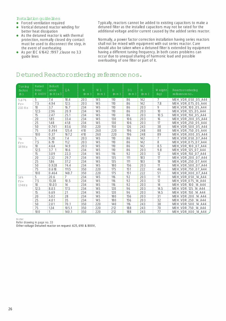
5 7.4 18.4 203 145 110 86 142 7 MEH_VDR_050_05_A447.5 4.94 12.5 203 145 110 86 142 7.8 MEH_VDR_075_05_A4410 3.7 16.7 234 145 110 86 203 9 MEH_VDR_100_05_A4412.5 2.96 20.9 234 145 110 86 203 10 MEH_VDR_125_05_A4415 2.47 25.1 234 145 110 86 203 10.5 MEH_VDR_150_05_A4420 1.85 33.4 234 145 130 106 203 16 MEH_VDR_200_05_A4425 1.48 41.8 234 145 130 106 203 17 MEH_VDR_250_05_A4450 0.741 83.6 350 220 150 126 243 38 MEH_VDR_500_05_A4475 0.494 125.4 410 260 220 196 248 88 MEH_VDR_750_05_A44100 0.37 167.2 410 260 220 196 248 89 MEH_VDR_X00_05_A445 9.28 7.4 203 145 110 86 142 7 MEH_VDR_050_07_A44
7.5 6.19 11.2 203 145 110 86 142 8 MEH_VDR_075_07_A4410 4.64 14.9 203 145 110 86 142 8.5 MEH_VDR_100_07_A4412.5 3.7 1 18.6 234 145 110 86 203 9.8 MEH_VDR_125_07_A4415 3.09 22.3 234 145 116 92 203 12 MEH_VDR_150_07_A4420 2.32 29.7 234 145 135 111 183 17 MEH_VDR_200_07_A4425 1.86 37.2 234 145 135 111 183 18 MEH_VDR_250_07_A4450 0.928 74.4 234 145 180 156 203 11 MEH_VDR_500_07_A4475 0.618 111.5 350 220 175 151 222 46 MEH_VDR_750_07_A44100 0.464 148.7 350 220 175 151 222 51 MEH_VDR_X00_07_A445 20.6 7 234 145 116 92 203 11 MEH_VDR_050_14_A447.5 13.38 10.5 234 145 116 92 203 12 MEH_VDR_075_14_A4410 10.03 14 234 145 116 92 203 14 MEH_VDR_100_14_A4412.5 8.03 17.5 234 145 120 96 203 14.5 MEH_VDR_125_14_A4415 6.69 21 234 145 120 96 203 14.5 MEH_VDR_150_14_A4420 5.02 28 234 145 180 156 203 31 MEH_VDR_200_14_A4425 4.01 35 234 145 180 156 203 32 MEH_VDR_250_14_A4450 2.01 70.1 350 220 140 116 243 38 MEH_VDR_500_14_A4475 1.34 105.1 350 220 212 188 243 70 MEH_VDR_750_14_A44100 1 140.1 350 220 212 188 243 77 MEH_VDR_X00_14_A44
Tuningfactor (%)
Rated kvar@ 440V
Inductance(mH) x 3
W(mm)
W1(mm)
D(mm)
D1 (mm)
H(mm)
Weight (kg)
I AN Reactor orderingreference no.
5.67%Fr = 210 Hz
7%Fr = 189Hz
14%Fr = 134Hz
Note:Refer drawing in page no. 33 Other voltage Detuned reactor on request :625, 690 & 800V,
Typically, reactors cannot be added to existing capacitors to make a detuned filter as the installed capacitors may not be rated for the additional voltage and/or current caused by the added series reactor.
Normally, a power factor correction installation having series reactors shall not be mixed with equipment with out series reactor. Care should also be taken when a detuned filter is extended by equipment having a different tuning frequency. In both cases problems can occur due to unequal sharing of harmonic load and possible overloading of one filter or part of it.
Detuned Reactor ordering reference nos.
26
Installation guidelinesl
l
l
l
Forced ventilation requiredVertical detuned reactor winding for better heat dissipationAs the detuned reactor is with thermal protection, normally closed dry contact must be used to disconnect the step, in the event of overheatingAs per IEC 61642 :1997 ,clause no 3.3 guide lines
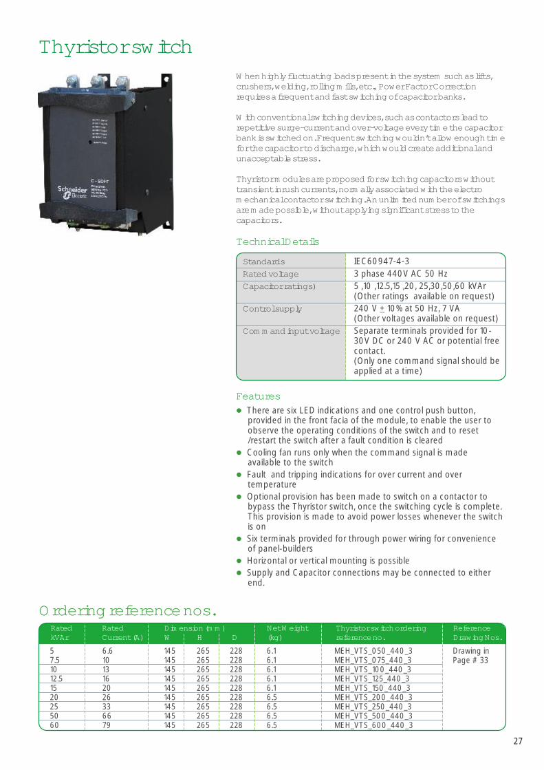
When highly fluctuating loadscrushers, welding, rolling mills, etc., Power Factor Correction requires a frequent and fast switching of capacitor banks.
With conventional switching devices, such as contactors lead to repetitive surge-current and over-voltage every time the capacitor bank is switched on. Frequent switching wouldn’t allow enough time for the capacitor to discharge, which would create additional and unacceptable stress.
Thyristor modules are proposed for switching capacitors without transient inrush currents, normally associated with the electro mechanical contactor switching. An unlimited number of switchings are made possible, without applying significant stress to the capacitors.
present in the system such as lifts,
Thyristor switch
RatedkVAr
5 6.6 145 265 228 6.1 MEH_VTS_050_440_3 Drawing in7.5 10 145 265 228 6.1 MEH_VTS_075_440_3 Page # 3310 13 145 265 228 6.1 MEH_VTS_100_440_312.5 16 145 265 228 6.1 MEH_VTS_125_440_315 20 145 265 228 6.1 MEH_VTS_150_440_320 26 145 265 228 6.5 MEH_VTS_200_440_325 33 145 265 228 6.5 MEH_VTS_250_440_350 66 145 265 228 6.5 MEH_VTS_500_440_360 79 145 265 228 6.5 MEH_VTS_600_440_3
RatedCurrent (A)
Net Weight(kg)
Dimension (mm)W H D
Reference Drawing Nos.
Thyristor switch orderingreference no.
Ordering reference nos.
Standards IEC60947-4-3Rated voltage 3 phase 440V AC 50 HzCapacitor ratings) 5 ,10 ,12.5,15 ,20, 25,30,50,60 kVAr
(Other ratings available on request)Control supply 240 V + 10% at 50 Hz, 7 VA
(Other voltages available on request) Command input voltage Separate terminals provided for 10-
30V DC or 240 V AC or potential free contact.(Only one command signal should be applied at a time)
Technical Details
l
l
l
l
l
l
l
There are six LED indications and one control push button, provided in the front facia of the module, to enable the user to observe the operating conditions of the switch and to reset /restart the switch after a fault condition is clearedCooling fan runs only when the command signal is made available to the switchFault and tripping indications for over current and over temperatureOptional provision has been made to switch on a contactor to bypass the Thyristor switch, once the switching cycle is complete. This provision is made to avoid power losses whenever the switch is onSix terminals provided for through power wiring for convenience of panel-buildersHorizontal or vertical mounting is possibleSupply and Capacitor connections may be connected to either end.
Features
27

ContactorsSpecial contactors LC1 D•K are designed for switching 3-phase, single or multiple-step capacitor banks. They conform to standards IEC 60070 and 60831, NFC 54-100, VDE 0560, UL and CSA.
These contactors are fitted with a block of early make poles and damping resistors, limiting the value of the current on closing to 60 IN max. This current limitation increases the life of all the components of the installation, in particular that of the fuses and capacitors.
Ordering Reference Nos.
440V 12.5 LC1DFK11**50 Hz 16.7 LC1DGK11**
20 LC1DLK11**25 LC1DMK11**C33.3 LC1DPK12**C40 LC1DTK12**C60 LC1DWK12**C
Voltage kVAr Contactor Ordering reference no.
*.Other voltages are available on request 400, 660, 690V contactor** COIL Voltage code
LC1-DFK….. DMK50/60HZ F7 M7 N7LC1-DPK…… DWK 50HZ F5 M5 N5
Voltage 110 220 415
28
Features
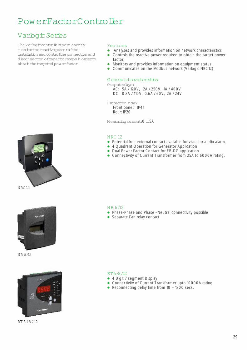
General characteristics
NRC 12l
l
l
l
NR 6/12l
l
RT6/8/12l
l
l
l
l
l
l
Analyses and provides information on network characteristicsControls the reactive power required to obtain the target power factor. Monitors and provides information on equipment status.Communicates on the Modbus network (Varlogic NRC12)
Output relays:AC: 5A / 120V, 2A / 250V, 1A / 400VDC: 0.3A / 110V, 0.6A / 60V, 2A / 24V
Protection IndexFront panel: IP41Rear: IP20
Measuring current: 0 … 5A
Potential free external contact available for visual or audio alarm.4 Quadrant Operation for Generator ApplicationDual Power Factor Contact for EB-DG applicationConnectivity of Current Transformer from 25A to 6000A rating.
Phase-Phase and Phase –Neutral connectivity possibleSeparate Fan relay contact
4 Digit 7 segment DisplayConnectivity of Current Transformer upto 10000A ratingReconnecting delay time from 10 – 1800 secs.
Power Factor ControllerVarlogic Series
NRC12
NR 6/12
RT 6 / 8 / 12
The Varlogic controllers permanently monitor the reactive power of the installation and control the connection and disconnection of capacitor steps in order to obtain the targeted power factor
29
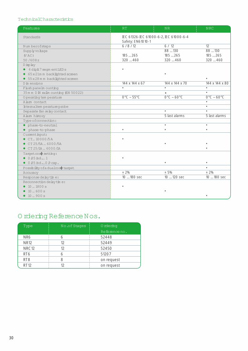
Technical Characteristics
Standards IEC 61326-IEC 61000-6-2, IEC 61000-6-4Safety: EN61010-1
Number of steps 6 / 8 / 12 6 / 12 12Supply voltage 88 … 130 88 … 130(V AC) 185 … 265 185 … 265 185 … 26550 / 60Hz 320 … 460 320 … 460 320 … 460Display
4 digit 7 segment LEDs •65 x 21 mm backlighted screen •55 x 28 mm backlighted screen •
Dimensions 144 x 144 x 67 144 x 144 x 70 144 x 144 x 80Flush panel mounting • • •35 mm DIN rail mounting (EN 50022) • •Operating temperature 0°C – 55°C 0°C – 60°C 0°C – 60°CAlarm contact •Internal temperature probe •Separate fan relay contact • •Alarm history 5 last alarms 5 last alarmsType of connection:
phase-to-neutral • •phase-to-phase • • •
Current input:CT… 10000/5 A •CT 25/5A … 6000/5A • •CT 25/1A … 6000/1A •
Target cos setting:0.85 ind. … 1 •0.85 ind. …0.9 cap. • •
Possibility of a dual cos target •Accuracy + 2% + 5% + 2%Response delay time: 10 … 180 sec 10 … 120 sec 10 … 180 secReconnection delay time:
10 … 1800 s •10 … 600 s •10 … 900 s •
l
l
l
l
l
l
l
l
l
l
l
l
l
ϕ
ϕ
Features RT NR NRC
Ordering Reference Nos.Type No. of Stages Ordering
Reference no.NR6 6 52448NR12 12 52449NRC12 12 52450RT6 6 51207RT8 8 on requestRT12 12 on request
30
Capacitors
1. ConstructionB= BoxC= Can
Reference Number Structure
1. kvar Example:
25 = 25 kvarX00= 100 kvar
Detuned reactors
M E H _ V B S D Y _ 1 2 5 A 4 4 _ 31 2 4 5 6 7
M E H _ V D R _ 2 5 0 _ 0 5 _ A 4 421 43
2. RangeSDY = Standard DutyHDY = Heavy Duty
GSF = Gas Heavy DutyENY = Energy
APP = Super Heavy Duty
3. Harmonic Duty RangeHH1 Harmonic HD 5.67 or 7%, 480VGH1 Harmonic GH 5.67 or 7%, 480VEH1 Harmonic Energy 5.67 or 7%, 480VGH2 Harmonic GH 14%, 525VHH2 Harmonic HD 14%, 525VEH2 Harmonic Energy 14%, 525VAH1 Harmonic APP 5.67 or 7%, 480VAH2 Harmonic APP 14%, 525V
4. kvar range Example:
125 = 12.5 kvarX00 = 100 kvar
2. Tuning05 = 5.67%07 = 7%14 = 14%
3. FrequencyA = 50HzB = 60Hz
4. Voltage44 = 440V
Mechanical DrawingsDrawing A Drawing B Drawing C Drawing D Drawing E
31
5. FrequencyA = 50HzB = 60Hz
6. Rated Voltage 41 = 415 V44 = 440 V
M E H _ V B E H 1 _ 0 5 0 A 4 4 _31 4 5 7 83
7. Network Voltage41 = 415V44 = 440V
H +
3 H
+3 +
t(t
)
D +1 + 5
D +1
H +
3
H +3
+ t
(t)
D +1 + 5
D +1
Finger proofClamptite Terminalin-built resistor type
D +1 + 5
H +
3 H
+3 +
t(t
)
D +1
Termination Cable
H +
2
H +2
+ (t
)
DischargeResistor
D +1
H +3
+ t
H +3
D +1 + 6
(t)
D +1
8. Number of phases1 = single phase3 = three-phase
Harmonic Capacitors
Drawing 1 Drawing 2
Drawing 4
32
H
W1 W3
D
Creepage Distance : 30mm
ClearancePhase to phase:25mm (min)Phase to earth :19mm (min)
Mounting DetailsMounting Screw M6 - 2 nos.
W2
Creepage Distance : 30mm
ClearancePhase to phase:25mm (min)Phase to earth :19mm (min)
Mounting DetailsMounting Screw M6 - 2 nos.
H
W3W1
W2
D
W1
W2
W3
Unit 1 Unit 2 Unit 3
D
H
Creepage Distance : 30mm
ClearancePhase to phase: 25mm (min)Phase to earth : 19mm (min)
Mounting DetailsMounting Screw M6 - 4 nos.
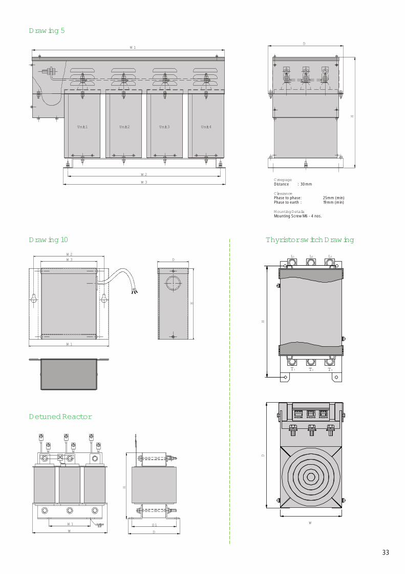
Drawing 5
Detuned Reactor
Thyristor switch Drawing
L1 L2 L3
T1 T2 T3
H
W
D
33
Unit 1 Unit 2 Unit 3 Unit 4
W1
W2
W3
D
H
Creepage Distance : 30mm
ClearancePhase to phase: 25mm (min)Phase to earth : 19mm (min)
Mounting DetailsMounting Screw M6 - 4 nos.
Drawing 10W2W3 D
H
W1
W1
WD1
D
H


For more information visit our website at: www.schneider-electric.co.in Schneider Electric India Pvt. Ltd. (A 100% subsidiary of Schneider Electric Industries SAS)
Corporate office: A-29, Mohan Co-operative Industrial Estate, New Delhi-110 044. Tel: 011-3940 4000. Fax: 4167 8010/11 Customer Care Centre: Toll Free: 1800 111 341 (BSNL/MTNL). 1800 1030 011 (Airtel) Phone: +91 11 4168 2434/35,
email: [email protected], website: www.schneider-electric.co.in
Global specialist in Energy Management
Visit us at: www.schneider-electric.co.in
For queries contact us at: Toll Free: 1800 111 341 (BSNL/MTNL) 1800 103 00 11 (Airtel) Phone: +91 11 4168 2434/35
SEI\P
FC\L
VC -C
AT\0
310\
V1