radar level transmitter - tek-trol
TRANSCRIPT
Technology Solutions
TEK-W AVE 4300ARadar Level Transmitter
Instruction ManualDocument Number: IM-4300A
www.tek-trol.com
© COPYRIGHT Tek-Trol LLC 2016
NOTICERead this manual before working with the product. For personal and system safety, and for optimumproduct performance, make sure you thoroughly understand the contents before installing, using, ormaintaining this product.For technical assistance, contactCustomer Support796 Tek-DriveCrystal Lake, IL 60014USATel: +1 847 857 6076, +1 847 655 7428
www.tek-trol.com
No part of this publication may be copied or distributed, transmitted, transcribed, stored in a retrieval system, or translated into any human or computer language, in any form or by any means, electronic, mechanical, manual, or otherwise, or disclosed to third parties without the express written permission. The information contained in this manual is subject to change without notice.
Table of Contents
1 Safety Instructions .................................................................................................... 2 1.1 Intended Use ............................................................................................................... 2 1.2 Safety Instructions from the Manufacturer ................................................................... 2
1.2.1 Disclaimer .......................................................................................................................... 2 1.2.2 Product Liability and Warranty ......................................................................................... 2 1.2.3 Information Concerning the Documentation .................................................................... 2
1.3 Safety Precautions ....................................................................................................... 2 1.4 Packaging, Transportation and Storage ......................................................................... 4
1.4.1 Packaging ........................................................................................................................... 4 1.4.2 Transportation................................................................................................................... 4 1.4.3 Storage .............................................................................................................................. 4 1.4.4 Nameplate ......................................................................................................................... 5
2 Product Description .................................................................................................. 6 2.1 Introduction ................................................................................................................ 6 2.2 Measuring Principle ..................................................................................................... 6 2.3 Specifications ............................................................................................................... 7 2.4 Dimensional Drawing ................................................................................................... 9
3 Installation.............................................................................................................. 10 3.1 Mounting................................................................................................................... 10 3.2 Distance from Tank’s Wall .......................................................................................... 11 3.3 Installation on Tanks with Domed Top ........................................................................ 12 3.4 Installation on Tanks with Obstruction ....................................................................... 12 3.5 Installation on Stilling Well and Stand Pipe ................................................................. 13
4 Electrical Installation ............................................................................................... 15 4.1 Wiring Information .................................................................................................... 16 4.2 2-Wire Sensor Wiring Connection ............................................................................... 16
5 Configuration .......................................................................................................... 17 5.1 Inside Tank Calibration ............................................................................................... 17 5.2 Outside Tank Calibration ............................................................................................ 19
6 Maintenance ........................................................................................................... 20
7 Troubleshooting ...................................................................................................... 21 7.1 Metal Stand Pipe Mounting ........................................................................................ 21 7.2 Multiple Reflections ................................................................................................... 21 7.3 False Level of Low Dielectric Materials ........................................................................ 22 7.4 Empty Tank with Coned Bottom ................................................................................. 22 7.5 Low Output Current and No Communication to PC...................................................... 23 7.6 Two Radar Units Close to Each Other .......................................................................... 23 7.7 Loss of Calibration...................................................................................................... 24
Instruction ManualTek-Wave 4300A
1
1 Safety Instructions 1.1 Intended Use
Tek-Wave 4300A is a radar level transmitter used for continuous and contactless level measurement of liquids. The device can only be mounted on closed metal tanks.
1.2 Safety Instructions from the Manufacturer
1.2.1 Disclaimer The manufacturer will not be held accountable for any damage that happens by using its product, including, but not limited to direct, indirect, or incidental and consequential damages. Any product purchased from the manufacturer is warranted in accordance with the relevant product documentation and our Terms and Conditions of Sale. The manufacturer has the right to modify the content of this document, including the disclaimer, at any time for any reason without prior notice, and will not be answerable in any way for the possible consequence of such changes
1.2.2 Product Liability and Warranty The operator shall bear authority for the suitability of the device for the specific application. The manufacturer accepts no liability for the consequences of misuse by the operator. Wrong installation or operation of the devices (systems) will cause the warranty to be void. The respective Terms and Conditions of Sale, which forms the basis for the sales contract shall also apply.
1.2.3 Information Concerning the Documentation To prevent any injury to the operator or damage to the device it is essential to read the information in this document and the applicable national standard safety instructions. This operating manual contain all the information that is required in various stages, such as product identification, incoming acceptance and storage, mounting, connection, operation and commissioning, troubleshooting, maintenance, and disposal.
1.3 Safety Precautions You must read these instructions carefully prior to installing and commissioning the device. These instructions are an important part of the product and must be kept for future reference. Only by observing these instructions, optimum protection of both personnel and the environment, as well as safe and fault-free operation of the device can be ensured.
Instruction ManualTek-Wave 4300A
2
For additional information that are not discussed in this manual, contact the manufacturer
Warnings and Symbols Used The following safety symbol marks are used in this operation manual and on the instrument.
WARNING
Indicates a potentially hazardous situation which, if not avoided, could result in death or serious injury
CAUTION
Indicates a potentially hazardous situation which, if not avoided, may result in minor or moderate injury. It may also be used to alert against unsafe practices.
NOTE
Indicates that operating the hardware or software in this manner may damage it or lead to system failure.
Instruction ManualTek-Wave 4300A
3
1.4 Packaging, Transportation and Storage
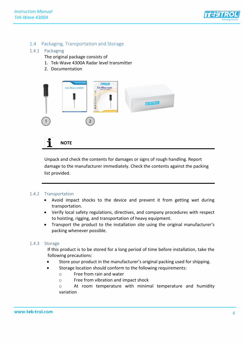
1.4.1 Packaging The original package consists of 1. Tek-Wave 4300A Radar level transmitter2. Documentation
NOTE
Unpack and check the contents for damages or signs of rough handling. Report damage to the manufacturer immediately. Check the contents against the packing list provided.
1.4.2 Transportation
• Avoid impact shocks to the device and prevent it from getting wet duringtransportation.
• Verify local safety regulations, directives, and company procedures with respectto hoisting, rigging, and transportation of heavy equipment.
• Transport the product to the installation site using the original manufacturer’spacking whenever possible.
1.4.3 Storage If this product is to be stored for a long period of time before installation, take the following precautions: • Store your product in the manufacturer’s original packing used for shipping.• Storage location should conform to the following requirements:
o Free from rain and watero Free from vibration and impact shocko At room temperature with minimal temperature and humidityvariation
Instruction ManualTek-Wave 4300A
4
• Before storing a used flowmeter remove any fluid from the flowmeter linecompletely. Properties of the instrument can change when stored outdoors.
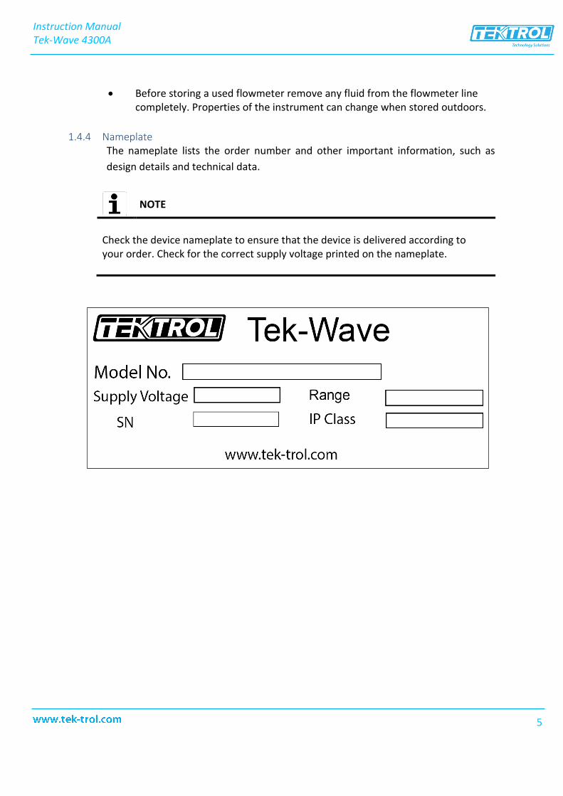
1.4.4 Nameplate The nameplate lists the order number and other important information, such as design details and technical data.
NOTE
Check the device nameplate to ensure that the device is delivered according to your order. Check for the correct supply voltage printed on the nameplate.
Instruction ManualTek-Wave 4300A
5
2 Product Description This section covers the reference and specification data, as well as ordering information.
2.1 Introduction Tek-Wave 4300A Radar level transmitter is a device for continuous level measurement that uses radar technology to measure the level of different types of media. The key advantage of this device is its ability to take reliable and accurate measurements even under extreme temperature and pressure conditions. It is not affected by the density, viscosity or the conductivity of the medium. Furthermore, since it does not come in contact with the media, it can also be used to measure levels of corrosive, viscous and abrasive materials without any damage.
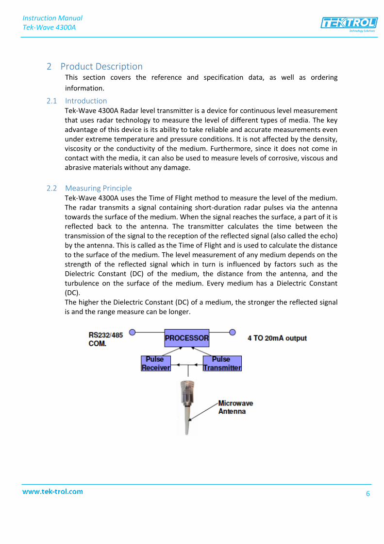
2.2 Measuring Principle Tek-Wave 4300A uses the Time of Flight method to measure the level of the medium. The radar transmits a signal containing short-duration radar pulses via the antenna towards the surface of the medium. When the signal reaches the surface, a part of it is reflected back to the antenna. The transmitter calculates the time between the transmission of the signal to the reception of the reflected signal (also called the echo) by the antenna. This is called as the Time of Flight and is used to calculate the distance to the surface of the medium. The level measurement of any medium depends on the strength of the reflected signal which in turn is influenced by factors such as the Dielectric Constant (DC) of the medium, the distance from the antenna, and the turbulence on the surface of the medium. Every medium has a Dielectric Constant (DC). The higher the Dielectric Constant (DC) of a medium, the stronger the reflected signal is and the range measure can be longer.
Instruction ManualTek-Wave 4300A
6
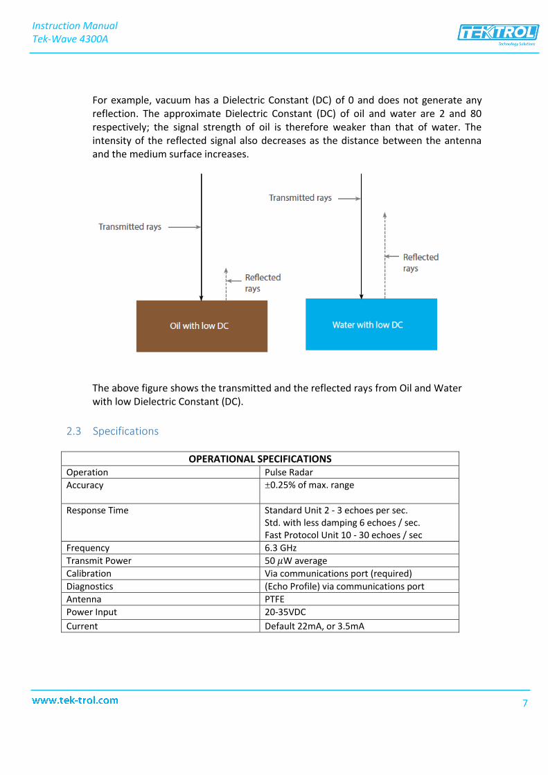
For example, vacuum has a Dielectric Constant (DC) of 0 and does not generate any reflection. The approximate Dielectric Constant (DC) of oil and water are 2 and 80 respectively; the signal strength of oil is therefore weaker than that of water. The intensity of the reflected signal also decreases as the distance between the antenna and the medium surface increases.
The above figure shows the transmitted and the reflected rays from Oil and Water with low Dielectric Constant (DC).
2.3 Specifications
OPERATIONAL SPECIFICATIONS Operation Pulse RadarAccuracy ±0.25% of max. range
Response Time Standard Unit 2 - 3 echoes per sec. Std. with less damping 6 echoes / sec. Fast Protocol Unit 10 - 30 echoes / sec
Frequency 6.3 GHzTransmit Power 50 𝜇W averageCalibration Via communications port (required)Diagnostics (Echo Profile) via communications portAntenna PTFEPower Input 20-35VDCCurrent Default 22mA, or 3.5mA
Instruction ManualTek-Wave 4300A
7
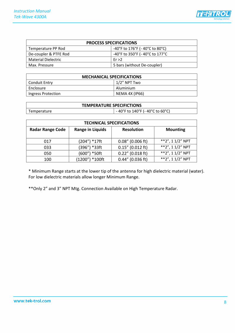
PROCESS SPECIFICATIONS Temperature PP Rod -40°F to 176°F (- 40°C to 80°C)De-coupler & PTFE Rod -40°F to 350°F (- 40°C to 177°CMaterial Dielectric Er >2 Max. Pressure 5 bars (without De-coupler)
MECHANICAL SPECIFICATIONS Conduit Entry 1/2” NPT Two Enclosure Aluminium Ingress Protection NEMA 4X (IP66)
TEMPERATURE SPECIFICTIONS Temperature - 40°F to 140°F (- 40°C to 60°C)
TECHNICAL SPECIFICATIONS
Radar Range Code Range in Liquids Resolution Mounting
017 (204”) *17ft 0.08” (0.006 ft) **2”, 1 1/2” NPT
033 (396”) *33ft 0.15” (0.012 ft) **2”, 1 1/2” NPT
050 (600”) *50ft 0.22” (0.018 ft) **2”, 1 1/2” NPT
100 (1200”) *100ft 0.44” (0.036 ft) **2”, 1 1/2” NPT
* Minimum Range starts at the lower tip of the antenna for high dielectric material (water).For low dielectric materials allow longer Minimum Range.
**Only 2” and 3” NPT Mtg. Connection Available on High Temperature Radar.
Instruction ManualTek-Wave 4300A
8
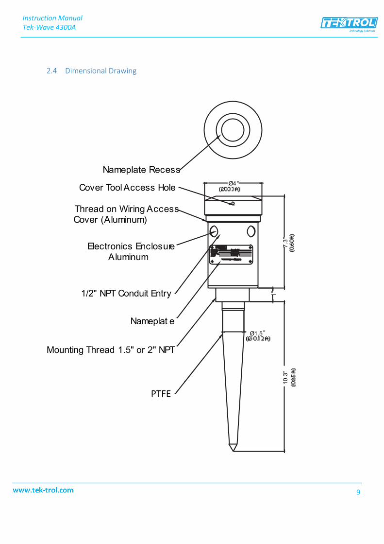
2.4 Dimensional Drawing
Instruction ManualTek-Wave 4300A
9
PTFE
3 Installation
This section covers instructions on installation and commissioning. Installation of the device must be carried out by trained, qualified specialists authorized to perform such works.
CAUTION
• When removing the instrument from hazardous processes, avoid direct contactwith the fluid and the meter
• All installation must comply with local installation requirements and localelectrical code
3.1 Mounting • The Tek-Wave 4300A has to be directed straight down to a discharge hole, even if
the material is not flat (sloped). This is typical for pellets/powder applications; thedevices will still receive an echo.
• When installed properly, the Tek-Wave 4300A transmit electromagnetic pulses downto the material (liquids or solids).
• During installation make sure that you do not have any large objects in front oftransducer or antenna.
• Reflected pulses from materials are received and processed to obtain correctdistances.
• Due to very narrow and uniform polar patterns (directivity) and signal processing ofultrasonic/ microwave devices, small unwanted echoes from tanks walls, ladders,filling pipes, etc. can be ignored or cancelled.
NOTE
The Tek-Wave 4300A can be used only in metal tanks
Instruction ManualTek-Wave 4300A
10
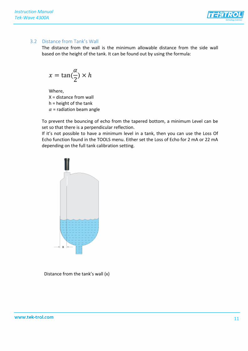
3.2 Distance from Tank’s Wall The distance from the wall is the minimum allowable distance from the side wall based on the height of the tank. It can be found out by using the formula:
𝑥 = tan(𝛼
2) × ℎ
Where, X = distance from wall h = height of the tank 𝛼 = radiation beam angle
To prevent the bouncing of echo from the tapered bottom, a minimum Level can be set so that there is a perpendicular reflection. If it’s not possible to have a minimum level in a tank, then you can use the Loss Of Echo function found in the TOOLS menu. Either set the Loss of Echo for 2 mA or 22 mA depending on the full tank calibration setting.
Distance from the tank’s wall (x)
Instruction ManualTek-Wave 4300A
11
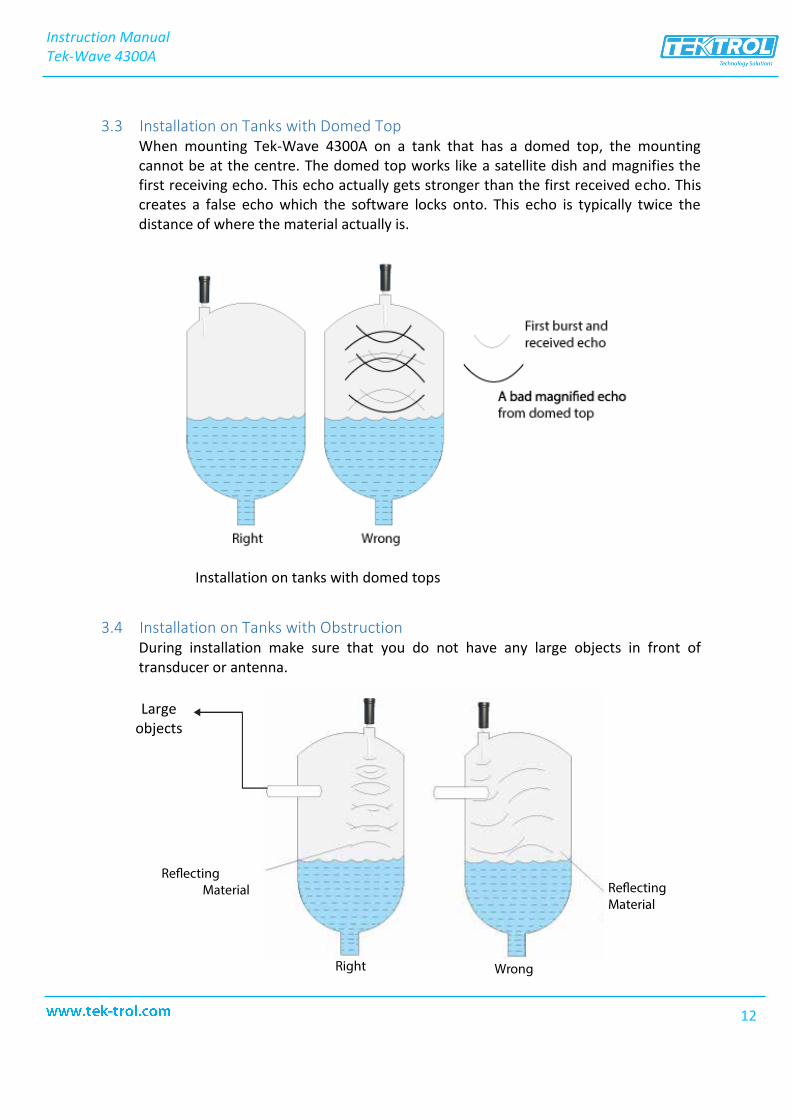
3.3 Installation on Tanks with Domed Top When mounting Tek-Wave 4300A on a tank that has a domed top, the mounting cannot be at the centre. The domed top works like a satellite dish and magnifies the first receiving echo. This echo actually gets stronger than the first received echo. This creates a false echo which the software locks onto. This echo is typically twice the distance of where the material actually is.
Installation on tanks with domed tops
3.4 Installation on Tanks with Obstruction During installation make sure that you do not have any large objects in front of transducer or antenna.
Instruction ManualTek-Wave 4300A
12
Right Wrong
MaterialMaterial
Large objects
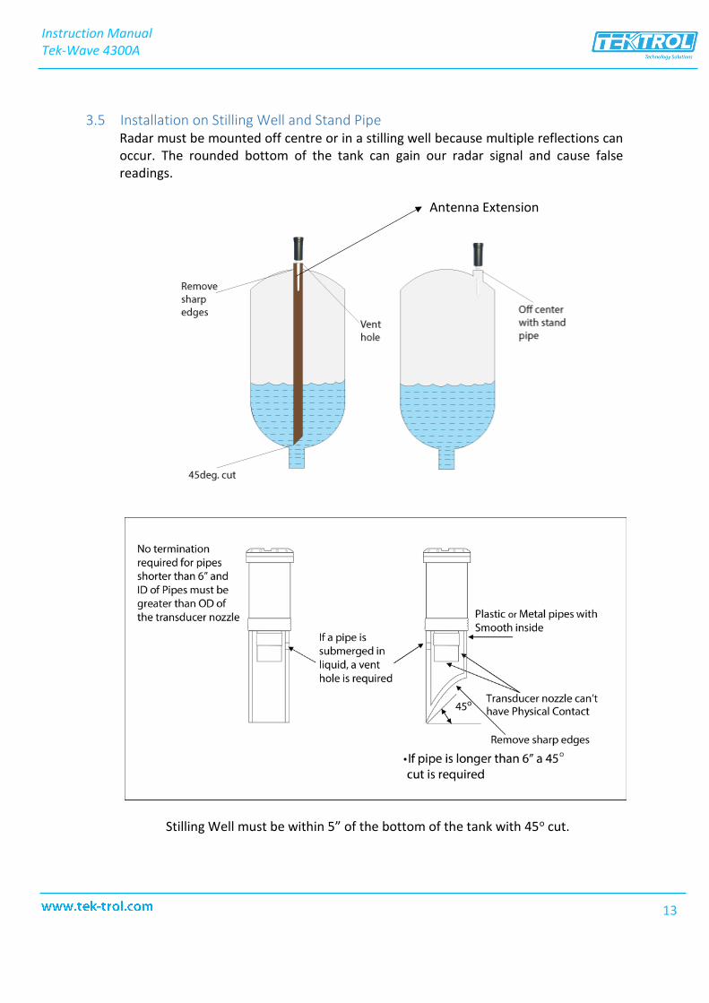
3.5 Installation on Stilling Well and Stand Pipe Radar must be mounted off centre or in a stilling well because multiple reflections can occur. The rounded bottom of the tank can gain our radar signal and cause false readings.
Stilling Well must be within 5” of the bottom of the tank with 45o cut.
Antenna Extension
Instruction ManualTek-Wave 4300A
13
4 Electrical Installation This section covers the all electrical connection requirement. Electrical connection of the device must be carried out by trained, qualified specialists authorized to perform such work by the installation site.
WARNING
• Connect all electrical cables when the power is switched off. If the device doesnot have switch-off elements, then, overcurrent protection devices, lightningprotection and/or energy isolating devices must be provided by the customer.
• The device must be grounded to a spot in accordance with regulations in orderto protect personnel against electric shocks.
NOTE
• When using the measuring device in hazardous areas, installation mustcomply with the corresponding national standards and regulations and theSafety Instructions or Installation or Control Drawings.
Instruction ManualTek-Wave 4300A
14
CAUTION
• Never mount the sensor at the center without stilling well. The stilling wellmust be within 5” of the bottom of the tank with 45o cut
• Stilling well must be made up of metal pipes• The sensor can’t have a physical contact with the stilling well• No metal caps should be there at the end of stilling well• The antenna extension is to ensure that the antenna exceeds the mounting• Match extensions with Teflon antenna only• 45o cut helps medium to make it into the stilling well• A vent hole is required at the top of the pipe
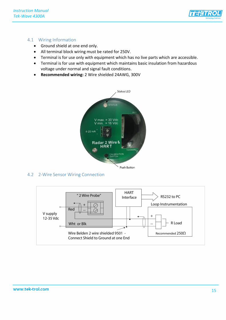
4.1 Wiring Information • Ground shield at one end only.• All terminal block wiring must be rated for 250V.• Terminal is for use only with equipment which has no live parts which are accessible.• Terminal is for use with equipment which maintains basic insulation from hazardous
voltage under normal and signal fault conditions.• Recommended wiring: 2 Wire shielded 24AWG, 300V
4.2 2-Wire Sensor Wiring Connection
Instruction ManualTek-Wave 4300A
15
5 Configuration This section covers the configuration and calibration of Tek-Wave 4300A Radar Level Transmitter.
NOTE
Calibrate the instrument according the instructions given in this section, otherwise there would be a measurement error
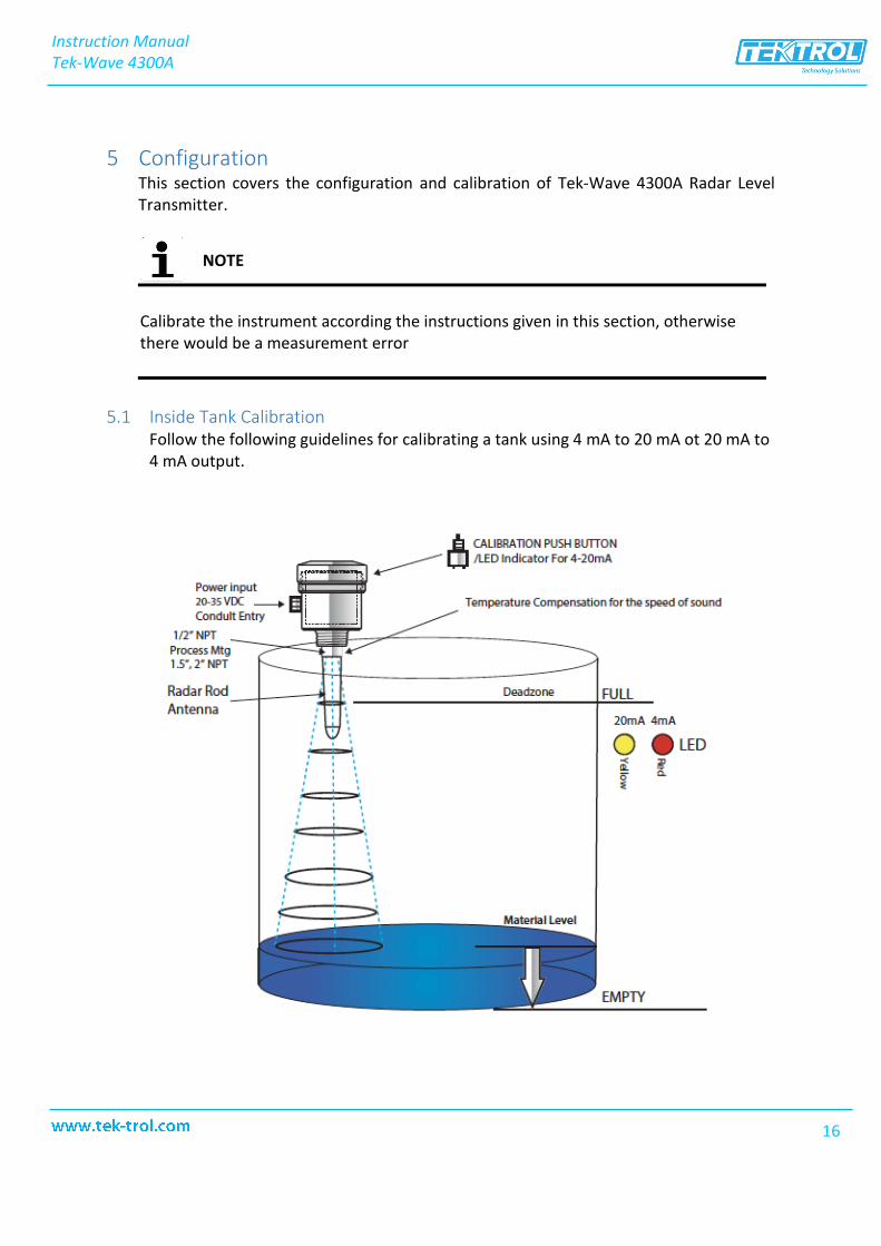
5.1 Inside Tank Calibration Follow the following guidelines for calibrating a tank using 4 mA to 20 mA ot 20 mA to 4 mA output.
Instruction ManualTek-Wave 4300A
16
FULL — Calibrate 20 mA or 4mA (Set Near Target) 1. Calibration mode LED color is blinking Green (for Radar, Low Dielectric Materials
has to be off).2. Push button and hold until LED turns Yellow (20 mA) or push button and hold
until LED turns Red (4 mA).3. Release button at Yellow or Red and observe LED flashes to acknowledge the
calibration.
EMPTY— Calibrate 4 mA or 20 mA (Set Far Target) 1. Calibration mode LED color is blinking Green (for Radar Low Dielectric Materials
has to be off).2. Push button and hold until LED turns Red (4 mA) or push button and hold until
LED turns Yellow (20 mA).3. Release button at Yellow or Red and observe LED flashes to acknowledge the
calibration.
For Radar in order to turn the low dielectric materials operation mode ON and OFF follow the following instructions
1. To turn the Low Dielectric Materials ON. Push button and hold until LED goesOFF after the sequence of Yellow, Red and turns Off. The Low Dielectric Materialoperation is on when the LED’S Green light gives two short blinks.
2. To turn the Low Dielectric Materials OFF. Push button and hold until LED goesOFF after the sequence of Yellow, Red and Turns OFF. The Low DielectricMaterial operation is OFF when LED is blinking Green.
3. Or use HART 7 communication software
NOTE
This mode is recommended for materials with dielectric materials lower than 4 and also to eliminate multiple reflections
Instruction ManualTek-Wave 4300A
17

5.2 Outside Tank Calibration • For calibration of an Empty Tank (4 mA calibration), position the level device at a
distance to a target equal to your empty tank level.• For Full Tank Calibration (20mA Calibration) place the level device at a distance equal
to a full tank.• In case of the radar do the positioning for a full tank when the radar is off. Make sure
the antenna is perpendicular to the metal target. After that, turn the unit on andwait a few seconds until the GREEN light is ON.
• The push button operation is explained in the Inside Tank Calibration (Section 5.1).
NOTE
For Radar, use a conductive (metallic) surface. Use 3 ft. x 3 ft. or larger target
Instruction ManualTek-Wave 4300A
18
6 Maintenance This section covers maintenance techniques and guidelines.
Occasionally check the transmitter face to ensure it remains clean and check that the cover seal, wiring, and cable glands are in good condition.
Instruction ManualTek-Wave 4300A
19
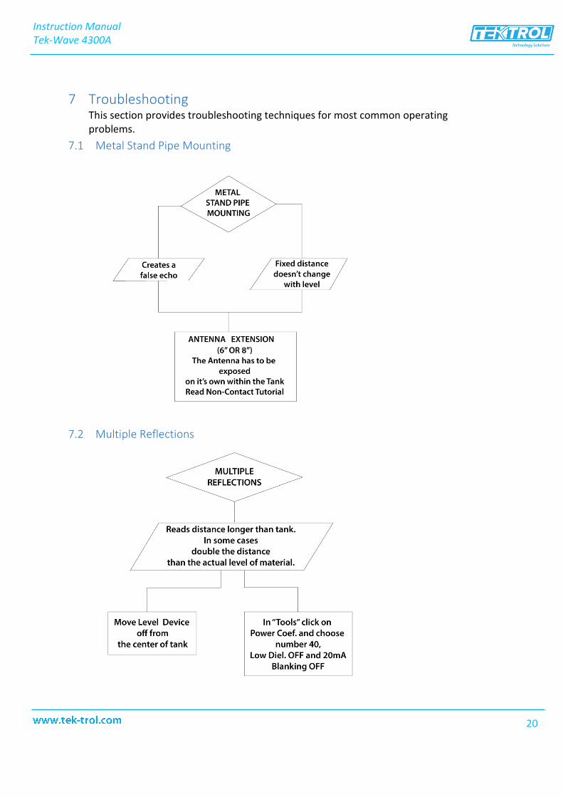
7 Troubleshooting This section provides troubleshooting techniques for most common operating problems.
7.1 Metal Stand Pipe Mounting
7.2 Multiple Reflections
Instruction ManualTek-Wave 4300A
20
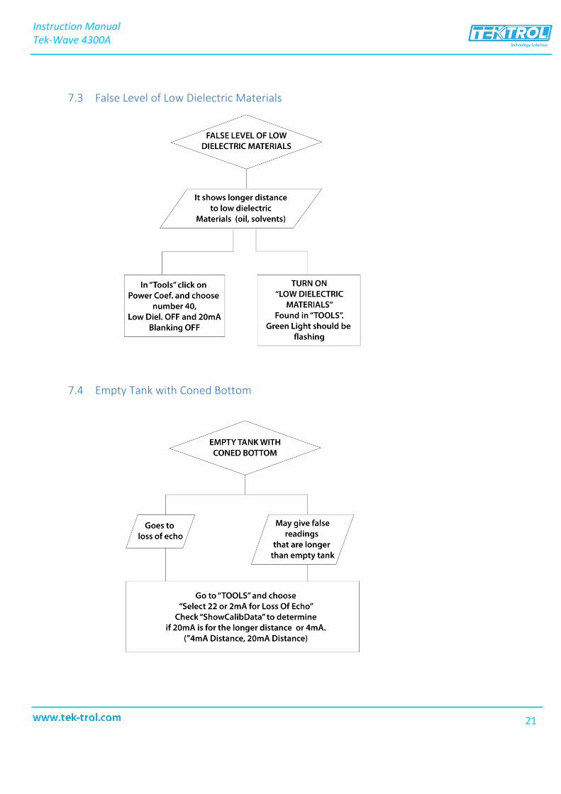
7.3 False Level of Low Dielectric Materials
7.4 Empty Tank with Coned Bottom
Instruction ManualTek-Wave 4300A
21

7.5 Low Output Current and No Communication to PC
7.6 Two Radar Units Close to Each Other
Instruction ManualTek-Wave 4300A
22
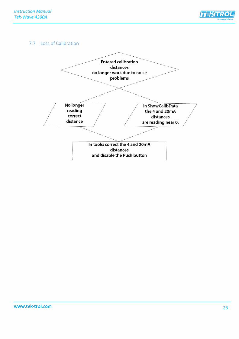
7.7 Loss of Calibration
Instruction ManualTek-Wave 4300A
23

TEKM
ATI
ON
LLC
rese
rves
the
right
to c
hang
e th
e de
sign
s an
d/or
mat
eria
ls o
f its
pro
duct
s w
ithou
t not
ice.
The
con
tent
s of
this
pub
licat
ion
are
the
prop
erty
of
TEK
MA
TIO
N a
nd c
anno
t be
repr
oduc
ed b
y an
y ot
her p
arty
with
out w
ritte
n pe
rmis
sion
. All
right
s re
serv
ed. C
opyr
ight
© 2
016
TEKM
ATI
ON
LLC
TEKM
ATI
ON
LLC
DO
C#TE
K/PO
/MN
L/20
0213
/430
0A/r
01
Tek-Trol LLC
www.tek-trol.com
Flow | Level | Temperature | Pressure | Valves | Analyzers | Accessories | TekValSys
Tek-Trol is a fully owned subsidiary of TEKMATION LLC. We o�er our customers a comprehensive range of products and solutionsfor process, power and oil & gas industries. Tek-Trol provides process measurement and control products for Flow, Level,
Temperature & Pressure Measurement, Control Valves & Analyzer systems. We are present in 15 locations globally and are knownfor our knowledge, innovative solutions, reliable products and global presence.
796 Tek Drive Crystal Lake, IL 60014 USATel.: +1 847 857 6076 , +1 847 655 7428 Fax: +1 847 655 6147
Email: [email protected]