quick start guide - jester's...
TRANSCRIPT
©2013 Taranis World Publications and Digital Media Products, a not for profit entity. FrSKY TARANIS is a trademark of FrSky
Electronics Co., Ltd and www.frsky-rc.com. FrSKY logo used with permission of FrSKY Electronics Co., Ltd.
Quick Start Guide Dec. 8, 2013
Understanding the Controls, Display Screens and Setup Menus
“Welcome to Taranis.” You’ve likely already powered up your Taranis and probably are a little bit
overwhelmed by all the screens and programming features. This quick start guide is meant to provide
new users of the Taranis, like yourself, with an introduction to the display screen views and methods for
navigating them using the menu buttons.
For each display screen graphic presented, this guide provides a brief description of the view’s features
and function. Also associated with each graphic is a menu button key which describes the button
presses required to access the screens and to change parameter settings for radio and model setups.
To supplement the brief screen descriptions, a glossary of terms, functions, and parameter labels is
provided. There’s also a flow chart that maps out how to navigate between the various screens.
Finally, as a foundation for model programming, a few flowcharts are provide to show programmatically
how inputs like gimbal sticks, switches, weights and limits are applied to functions and mixes, and in
which order, to compute the receiver channel outputs. Let’s get started!

©2013 Taranis World Publications and Digital Media Products, a not for profit entity. FrSKY TARANIS is a trademark of FrSky
Electronics Co., Ltd and www.frsky-rc.com. FrSKY logo used with permission of FrSKY Electronics Co., Ltd.
Credits:
I want to offer profound appreciation to all that volunteered to bring this project to fruition
Despite the best efforts the people that have reviewed the document there are certainly errors and
ambiguities,. Please send corrections to [email protected] for incorporation in future
editions.
Appreciation to Alofthobbies.com for hosting this document on their server.
3
Introduction
This document provides a broad overview of Taranis’s control hardware and firmware features.
Background information on the transmitters controls, battery charging, and receiver binding is
discussed. More detailed information may be provided in the Taranis X9D Manual by FrSKY or by the
openTx web page for Taranis.
One especially nice feature of Taranis is its USB port and the ability to connect to a PC for firmware
updates, transferring data files, and model programming. A mini-B USB cable and the openTx open
source software Companion9x provide this capability. However, Companion9x is not necessary for
model setup and programming. For some, model programming will be easier when done directly on
the Taranis, while for others not. Regardless, in the field, it may not be practical make adjustments by a
PC, so learning the screens and menus directly from Taranis is essential. This document does not
discuss setting up or using Companion9x on a PC.
This document is based on the latest firmware at the time of the writing, so screens presented may be
slightly different on your radio due to the firmware version installed. The intent is to update this guide
periodically or when reasonable. The user should also update their own firmware as the releases
become available to take advantage of the new features and firmware fixes.
Familiarity with the Transmitter Layout and Controls
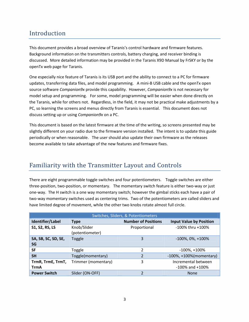
There are eight programmable toggle switches and four potentiometers. Toggle switches are either
three-position, two-position, or momentary. The momentary switch feature is either two-way or just
one-way. The H switch is a one way momentary switch; however the gimbal sticks each have a pair of
two-way momentary switches used as centering trims. Two of the potentiometers are called sliders and
have limited degree of movement, while the other two knobs rotate almost full circle.
Switches, Sliders, & Potentiometers
Identifier/Label Type Number of Positions Input Value by Position
S1, S2, RS, LS Knob/Slider (potentiometer)
Proportional -100% thru +100%
SA, SB, SC, SD, SE, SG
Toggle 3 -100%, 0%, +100%
SF Toggle 2 -100%, +100%
SH Toggle(momentary) 2 -100%, +100%(momentary)
TrmR, TrmE, TrmT, TrmA
Trimmer (momentary) 3 Incremental between -100% and +100%
Power Switch Slider (ON-OFF) 2 None
4
The power switch is also a slider switch, but not programmable. All other switches, sliders and knobs
are fully programmable and can be used for a variety of tasks. A typical use of switches is for changing
flight modes which alter the model’s control surfaces for a variety of performance characteristics, such
as for taking off, cruising, or landing. Switches can also be used to start and stop timers, trigger
playback of audio recordings, and to announce telemetry values sent back as data from the model’s
sensors.
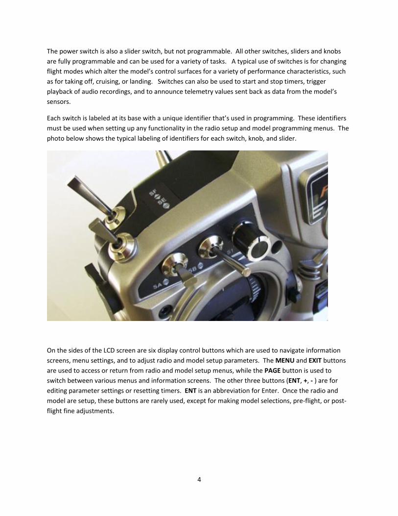
Each switch is labeled at its base with a unique identifier that’s used in programming. These identifiers
must be used when setting up any functionality in the radio setup and model programming menus. The
photo below shows the typical labeling of identifiers for each switch, knob, and slider.
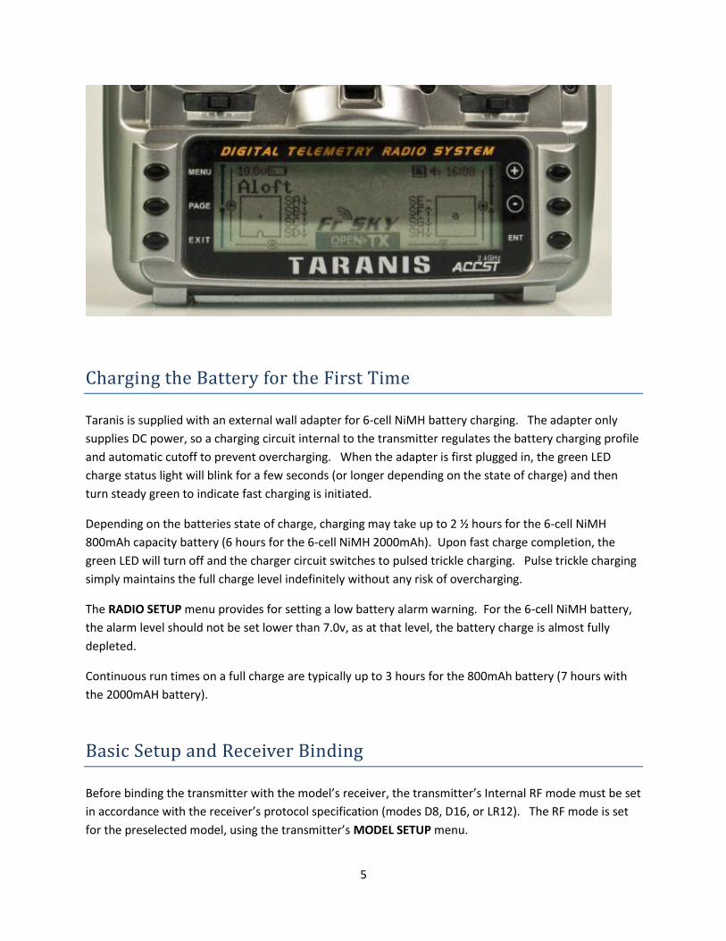
On the sides of the LCD screen are six display control buttons which are used to navigate information
screens, menu settings, and to adjust radio and model setup parameters. The MENU and EXIT buttons
are used to access or return from radio and model setup menus, while the PAGE button is used to
switch between various menus and information screens. The other three buttons (ENT, +, - ) are for
editing parameter settings or resetting timers. ENT is an abbreviation for Enter. Once the radio and
model are setup, these buttons are rarely used, except for making model selections, pre-flight, or post-
flight fine adjustments.
5
Charging the Battery for the First Time
Taranis is supplied with an external wall adapter for 6-cell NiMH battery charging. The adapter only
supplies DC power, so a charging circuit internal to the transmitter regulates the battery charging profile
and automatic cutoff to prevent overcharging. When the adapter is first plugged in, the green LED
charge status light will blink for a few seconds (or longer depending on the state of charge) and then
turn steady green to indicate fast charging is initiated.
Depending on the batteries state of charge, charging may take up to 2 ½ hours for the 6-cell NiMH
800mAh capacity battery (6 hours for the 6-cell NiMH 2000mAh). Upon fast charge completion, the
green LED will turn off and the charger circuit switches to pulsed trickle charging. Pulse trickle charging
simply maintains the full charge level indefinitely without any risk of overcharging.
The RADIO SETUP menu provides for setting a low battery alarm warning. For the 6-cell NiMH battery,
the alarm level should not be set lower than 7.0v, as at that level, the battery charge is almost fully
depleted.
Continuous run times on a full charge are typically up to 3 hours for the 800mAh battery (7 hours with
the 2000mAH battery).
Basic Setup and Receiver Binding
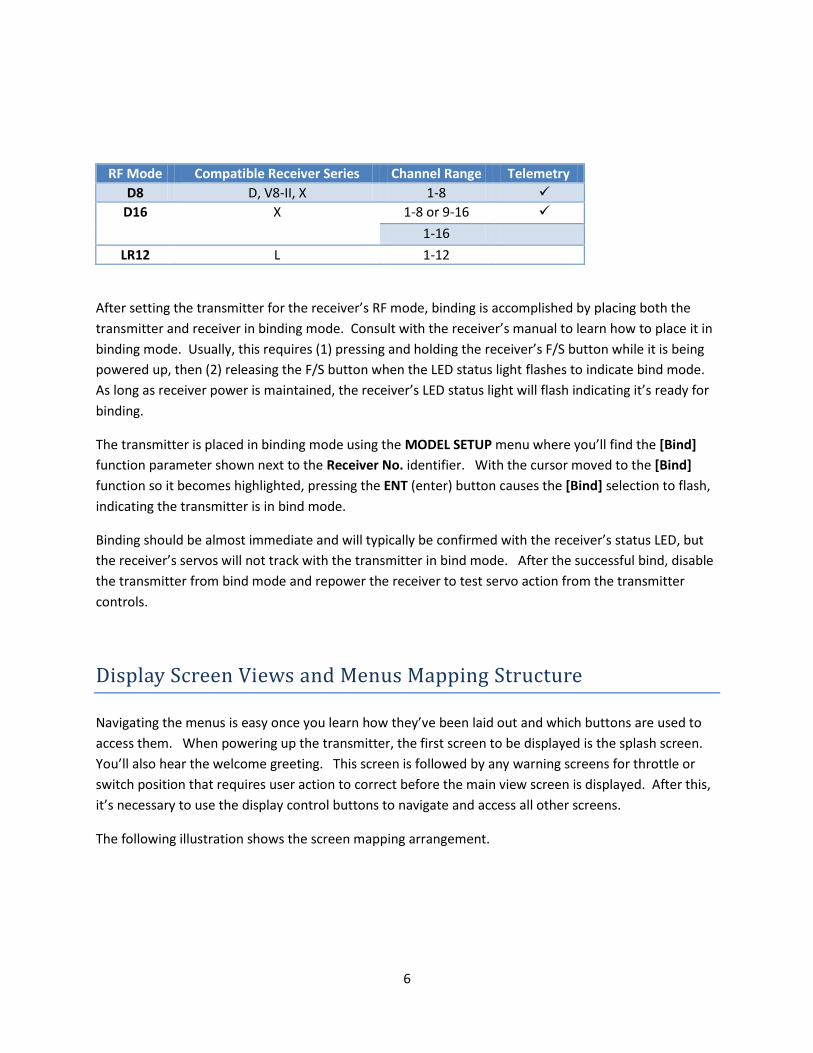
Before binding the transmitter with the model’s receiver, the transmitter’s Internal RF mode must be set
in accordance with the receiver’s protocol specification (modes D8, D16, or LR12). The RF mode is set
for the preselected model, using the transmitter’s MODEL SETUP menu.
6
RF Mode Compatible Receiver Series Channel Range Telemetry
D8 D, V8-II, X 1-8
D16 X 1-8 or 9-16
1-16
LR12 L 1-12
After setting the transmitter for the receiver’s RF mode, binding is accomplished by placing both the
transmitter and receiver in binding mode. Consult with the receiver’s manual to learn how to place it in
binding mode. Usually, this requires (1) pressing and holding the receiver’s F/S button while it is being
powered up, then (2) releasing the F/S button when the LED status light flashes to indicate bind mode.
As long as receiver power is maintained, the receiver’s LED status light will flash indicating it’s ready for
binding.
The transmitter is placed in binding mode using the MODEL SETUP menu where you’ll find the [Bind]
function parameter shown next to the Receiver No. identifier. With the cursor moved to the [Bind]
function so it becomes highlighted, pressing the ENT (enter) button causes the [Bind] selection to flash,
indicating the transmitter is in bind mode.
Binding should be almost immediate and will typically be confirmed with the receiver’s status LED, but
the receiver’s servos will not track with the transmitter in bind mode. After the successful bind, disable
the transmitter from bind mode and repower the receiver to test servo action from the transmitter
controls.
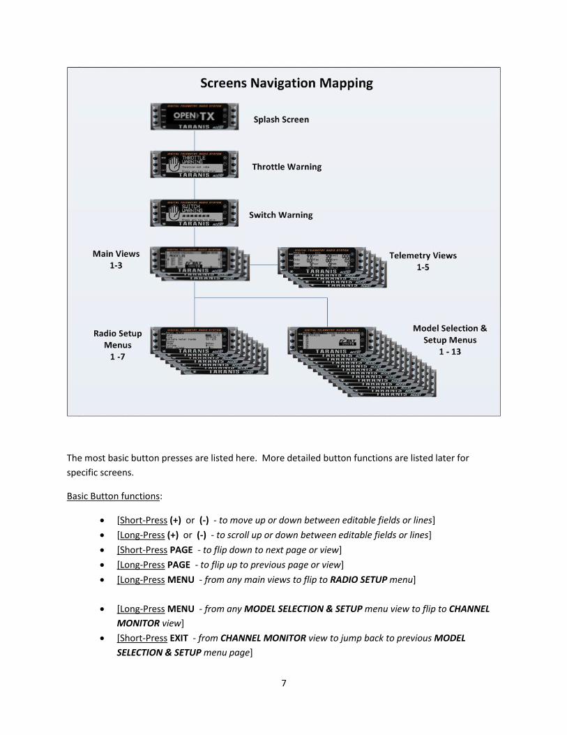
Display Screen Views and Menus Mapping Structure
Navigating the menus is easy once you learn how they’ve been laid out and which buttons are used to
access them. When powering up the transmitter, the first screen to be displayed is the splash screen.
You’ll also hear the welcome greeting. This screen is followed by any warning screens for throttle or
switch position that requires user action to correct before the main view screen is displayed. After this,
it’s necessary to use the display control buttons to navigate and access all other screens.
The following illustration shows the screen mapping arrangement.
7
The most basic button presses are listed here. More detailed button functions are listed later for
specific screens.
Basic Button functions:
[Short-Press (+) or (-) - to move up or down between editable fields or lines]
[Long-Press (+) or (-) - to scroll up or down between editable fields or lines]
[Short-Press PAGE - to flip down to next page or view]
[Long-Press PAGE - to flip up to previous page or view]
[Long-Press MENU - from any main views to flip to RADIO SETUP menu]
[Long-Press MENU - from any MODEL SELECTION & SETUP menu view to flip to CHANNEL
MONITOR view]
[Short-Press EXIT - from CHANNEL MONITOR view to jump back to previous MODEL
SELECTION & SETUP menu page]
8
Two-key combination Shortcuts:
[(+) + (-) - to invert value (from 30 to -30)]
[(-) + ENT - to set value to 100]
[PAGE + EXIT - to set a value to -100]
[PAGE + MENU - to set a value to 0]
Toggle Switch/Knob/Slider Parameter Selection Shortcut:
Physically move the desired toggle switch, knob, or slider instead of selecting it from any
menu switch pick list.
Display Screens Overview
The following table provides brief descriptions of the various information screens and setup menus by
topic. The description for each screen tries to explain the most cryptic parts, but not every parameter is
discussed. Immediately following this table, you’ll find a glossary of terms, functions and parameters
that may explain details not mentioned.
Startup Screens
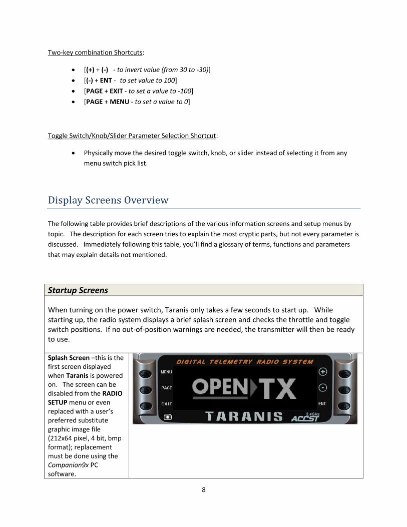
When turning on the power switch, Taranis only takes a few seconds to start up. While starting up, the radio system displays a brief splash screen and checks the throttle and toggle switch positions. If no out-of-position warnings are needed, the transmitter will then be ready to use.
Splash Screen –this is the first screen displayed when Taranis is powered on. The screen can be disabled from the RADIO SETUP menu or even replaced with a user’s preferred substitute graphic image file (212x64 pixel, 4 bit, bmp format); replacement must be done using the Companion9x PC software.
9
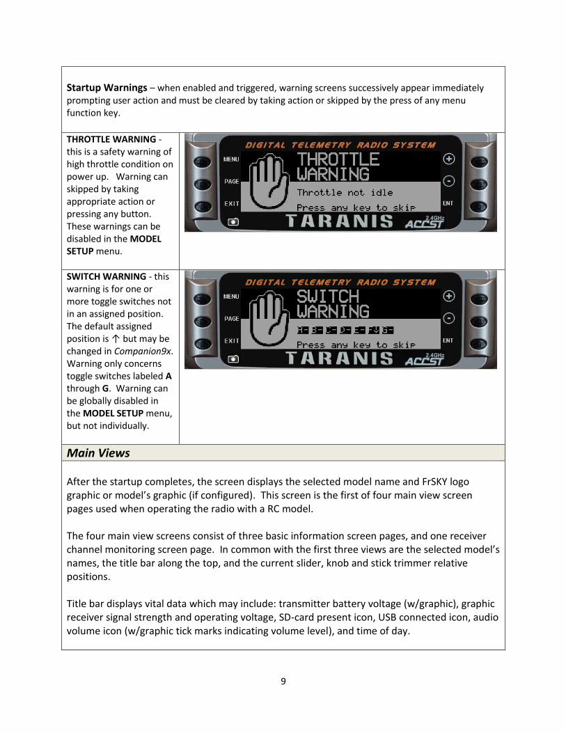
Startup Warnings – when enabled and triggered, warning screens successively appear immediately prompting user action and must be cleared by taking action or skipped by the press of any menu function key.
THROTTLE WARNING - this is a safety warning of high throttle condition on power up. Warning can skipped by taking appropriate action or pressing any button. These warnings can be disabled in the MODEL SETUP menu.
SWITCH WARNING - this warning is for one or more toggle switches not in an assigned position. The default assigned position is ↑ but may be changed in Companion9x. Warning only concerns toggle switches labeled A through G. Warning can be globally disabled in the MODEL SETUP menu, but not individually.
Main Views After the startup completes, the screen displays the selected model name and FrSKY logo graphic or model’s graphic (if configured). This screen is the first of four main view screen pages used when operating the radio with a RC model. The four main view screens consist of three basic information screen pages, and one receiver channel monitoring screen page. In common with the first three views are the selected model’s names, the title bar along the top, and the current slider, knob and stick trimmer relative positions. Title bar displays vital data which may include: transmitter battery voltage (w/graphic), graphic receiver signal strength and operating voltage, SD-card present icon, USB connected icon, audio volume icon (w/graphic tick marks indicating volume level), and time of day.
10
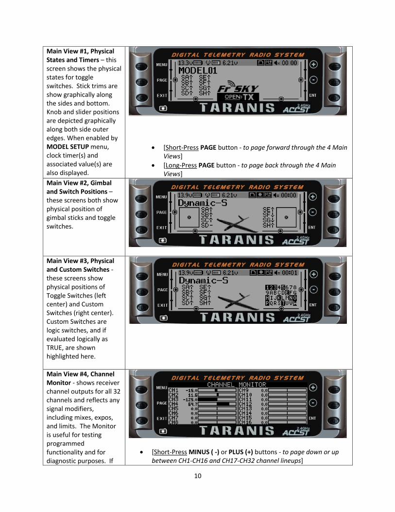
Main View #1, Physical States and Timers – this screen shows the physical states for toggle switches. Stick trims are show graphically along the sides and bottom. Knob and slider positions are depicted graphically along both side outer edges. When enabled by MODEL SETUP menu, clock timer(s) and associated value(s) are also displayed.
[Short-Press PAGE button - to page forward through the 4 Main Views]
[Long-Press PAGE button - to page back through the 4 Main Views]
Main View #2, Gimbal and Switch Positions – these screens both show physical position of gimbal sticks and toggle switches.
Main View #3, Physical and Custom Switches - these screens show physical positions of Toggle Switches (left center) and Custom Switches (right center). Custom Switches are logic switches, and if evaluated logically as TRUE, are shown highlighted here.
Main View #4, Channel Monitor - shows receiver channel outputs for all 32 channels and reflects any signal modifiers, including mixes, expos, and limits. The Monitor is useful for testing programmed functionality and for diagnostic purposes. If
[Short-Press MINUS ( -) or PLUS (+) buttons - to page down or up between CH1-CH16 and CH17-CH32 channel lineups]
11
channel numbers are named (e.g., Thr, Ail, Ele) in the model’s SERVOS menu, those names will be shown here. Virtual channels assigned in mixes will appear as well.
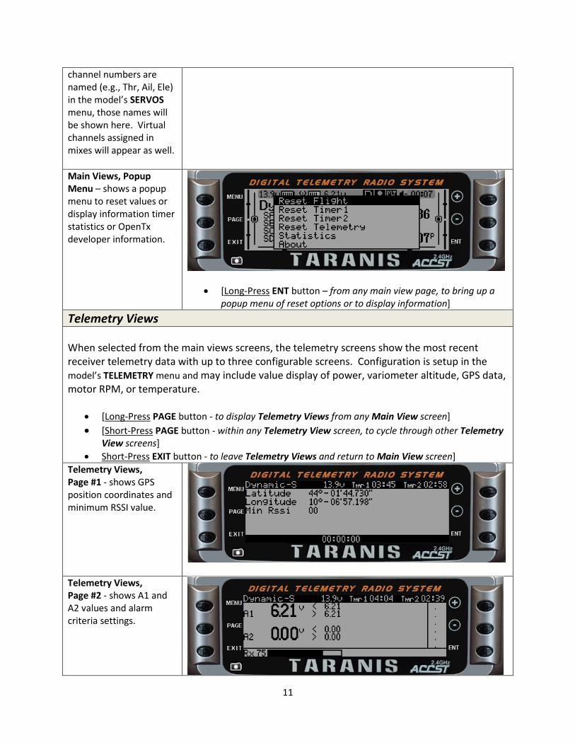
Main Views, Popup Menu – shows a popup menu to reset values or display information timer statistics or OpenTx developer information.
[Long-Press ENT button – from any main view page, to bring up a popup menu of reset options or to display information]
Telemetry Views When selected from the main views screens, the telemetry screens show the most recent receiver telemetry data with up to three configurable screens. Configuration is setup in the model’s TELEMETRY menu and may include value display of power, variometer altitude, GPS data, motor RPM, or temperature.
[Long-Press PAGE button - to display Telemetry Views from any Main View screen]
[Short-Press PAGE button - within any Telemetry View screen, to cycle through other Telemetry View screens]
Short-Press EXIT button - to leave Telemetry Views and return to Main View screen]
Telemetry Views, Page #1 - shows GPS position coordinates and minimum RSSI value.
Telemetry Views, Page #2 - shows A1 and A2 values and alarm criteria settings.
12
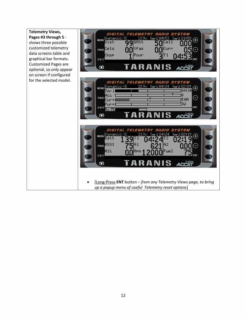
Telemetry Views, Pages #3 through 5 - shows three possible customized telemetry data screens table and graphical bar formats. Customized Pages are optional, so only appear on screen if configured for the selected model.
[Long-Press ENT button – from any Telemetry Views page, to bring up a popup menu of useful Telemetry reset options]
13
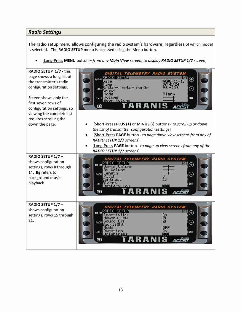
Radio Settings The radio setup menu allows configuring the radio system’s hardware, regardless of which model is selected. The RADIO SETUP menu is accessed using the Menu button.
[Long-Press MENU button – from any Main View screen, to display RADIO SETUP 1/7 screen]
RADIO SETUP 1/7 - this page shows a long list of the transmitter’s radio configuration settings. Screen shows only the first seven rows of configuration settings, so viewing the complete list requires scrolling the down the page.
[Short-Press PLUS (+) or MINUS (-) buttons - to scroll up or down the list of transmitter configuration settings]
[Short-Press PAGE button - to page down view screens from any of RADIO SETUP 1/7 screens]
[Long-Press PAGE button - to page up view screens from any of the RADIO SETUP 1/7 screens]
RADIO SETUP 1/7 – shows configuration settings, rows 8 through 14. Bg refers to background music playback.
RADIO SETUP 1/7 – shows configuration settings, rows 15 through 21.
14
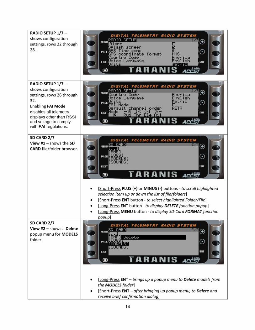
RADIO SETUP 1/7 – shows configuration settings, rows 22 through 28.
RADIO SETUP 1/7 – shows configuration settings, rows 26 through 32. Enabling FAI Mode disables all telemetry
displays other than RSSI and voltage to comply with FAI regulations.
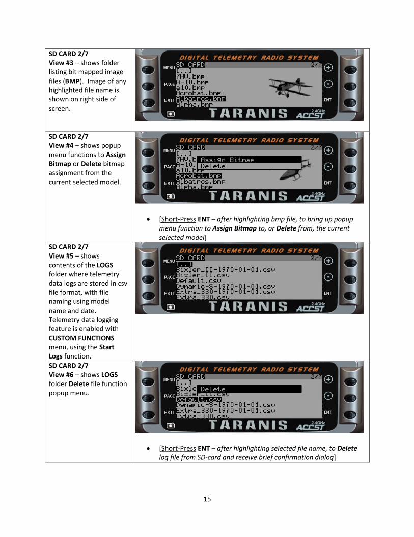
SD CARD 2/7 View #1 – shows the SD CARD file/folder browser.
[Short-Press PLUS (+) or MINUS (-) buttons - to scroll highlighted selection item up or down the list of file/folders]
[Short-Press ENT button - to select highlighted Folder/File]
[Long-Press ENT button - to display DELETE function popup]
[Long-Press MENU button - to display SD-Card FORMAT function popup]
SD CARD 2/7 View #2 – shows a Delete popup menu for MODELS folder.
[Long-Press ENT – brings up a popup menu to Delete models from the MODELS folder]
[Short-Press ENT – after bringing up popup menu, to Delete and receive brief confirmation dialog]
15
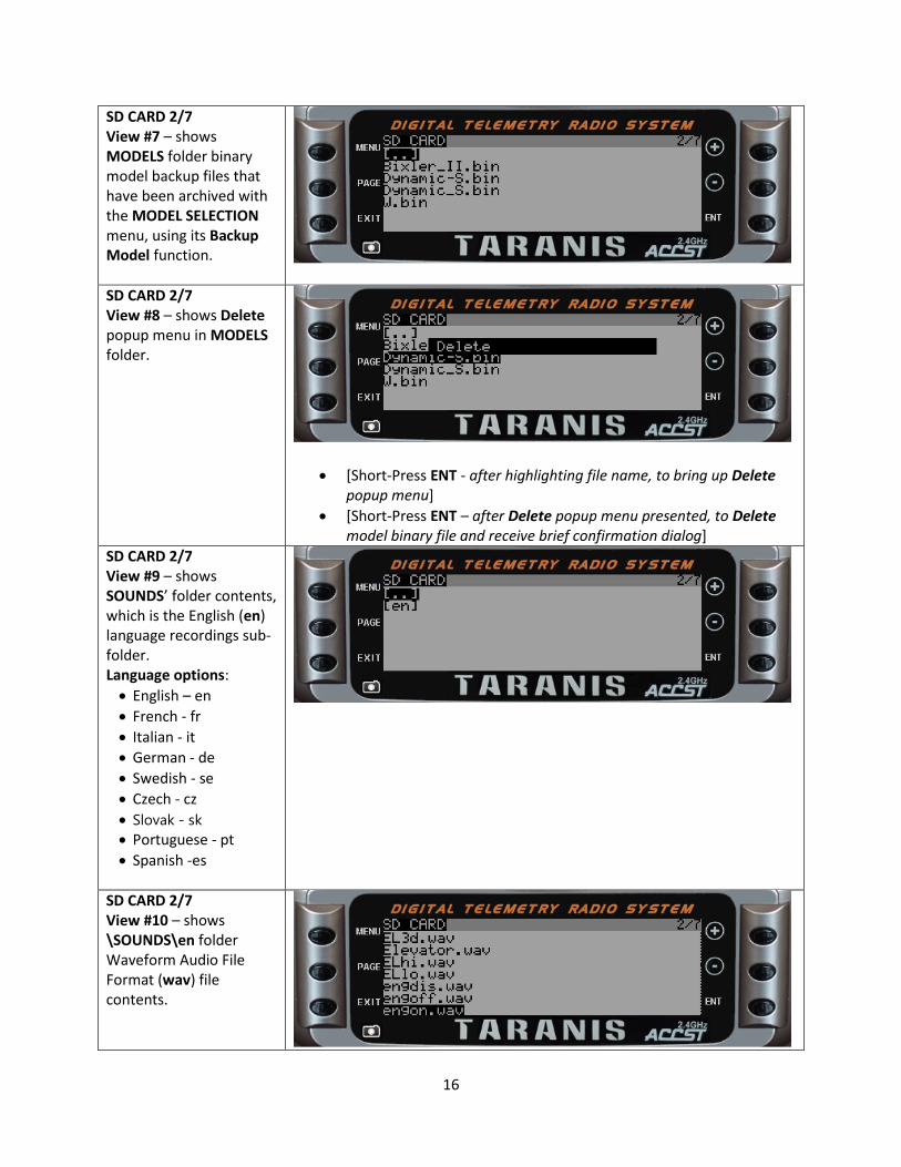
SD CARD 2/7 View #3 – shows folder listing bit mapped image files (BMP). Image of any highlighted file name is shown on right side of screen.
SD CARD 2/7 View #4 – shows popup menu functions to Assign Bitmap or Delete bitmap assignment from the current selected model.
[Short-Press ENT – after highlighting bmp file, to bring up popup menu function to Assign Bitmap to, or Delete from, the current selected model]
SD CARD 2/7 View #5 – shows contents of the LOGS folder where telemetry data logs are stored in csv file format, with file naming using model name and date. Telemetry data logging feature is enabled with CUSTOM FUNCTIONS menu, using the Start Logs function.
SD CARD 2/7 View #6 – shows LOGS folder Delete file function popup menu.
[Short-Press ENT – after highlighting selected file name, to Delete log file from SD-card and receive brief confirmation dialog]
16
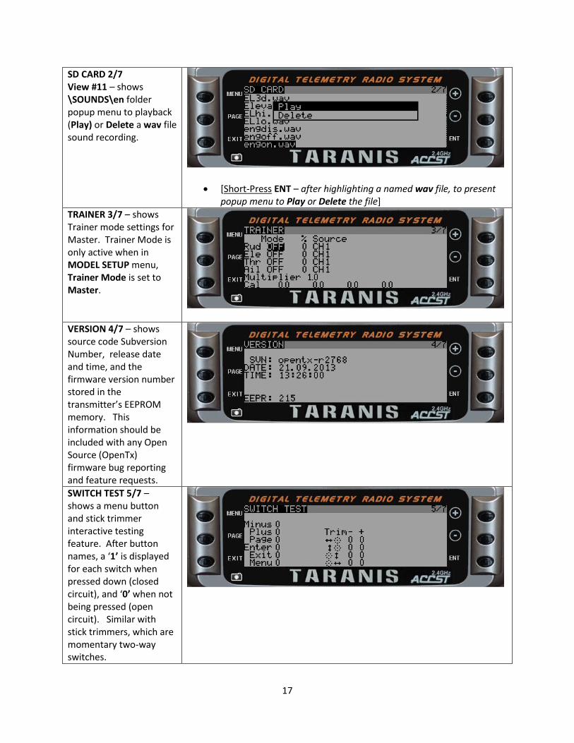
SD CARD 2/7 View #7 – shows MODELS folder binary model backup files that have been archived with the MODEL SELECTION menu, using its Backup Model function.
SD CARD 2/7 View #8 – shows Delete popup menu in MODELS folder.
[Short-Press ENT - after highlighting file name, to bring up Delete popup menu]
[Short-Press ENT – after Delete popup menu presented, to Delete model binary file and receive brief confirmation dialog]
SD CARD 2/7 View #9 – shows SOUNDS’ folder contents, which is the English (en) language recordings sub-folder. Language options:
English – en
French - fr
Italian - it
German - de
Swedish - se
Czech - cz
Slovak - sk Portuguese - pt
Spanish -es
SD CARD 2/7 View #10 – shows \SOUNDS\en folder Waveform Audio File Format (wav) file contents.
17
SD CARD 2/7 View #11 – shows \SOUNDS\en folder popup menu to playback (Play) or Delete a wav file sound recording.
[Short-Press ENT – after highlighting a named wav file, to present popup menu to Play or Delete the file]
TRAINER 3/7 – shows Trainer mode settings for Master. Trainer Mode is only active when in MODEL SETUP menu, Trainer Mode is set to Master.
VERSION 4/7 – shows source code Subversion Number, release date and time, and the firmware version number stored in the transmitter’s EEPROM memory. This information should be included with any Open Source (OpenTx) firmware bug reporting and feature requests.
SWITCH TEST 5/7 – shows a menu button and stick trimmer interactive testing feature. After button names, a ‘1’ is displayed for each switch when pressed down (closed circuit), and ‘0’ when not being pressed (open circuit). Similar with stick trimmers, which are momentary two-way switches.
18
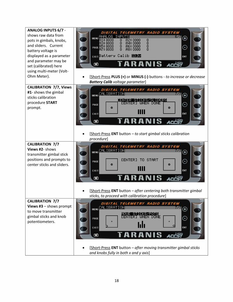
ANALOG INPUTS 6/7 - shows raw data from pots in gimbals, knobs, and sliders. Current battery voltage is displayed as a parameter and parameter may be set (calibrated) here using multi-meter (Volt-Ohm Meter).
[Short-Press PLUS (+) or MINUS (-) buttons - to increase or decrease Battery Calib voltage parameter]
CALIBRATION 7/7, Views #1- shows the gimbal sticks calibration procedure START prompt.
[Short-Press ENT button – to start gimbal sticks calibration procedure]
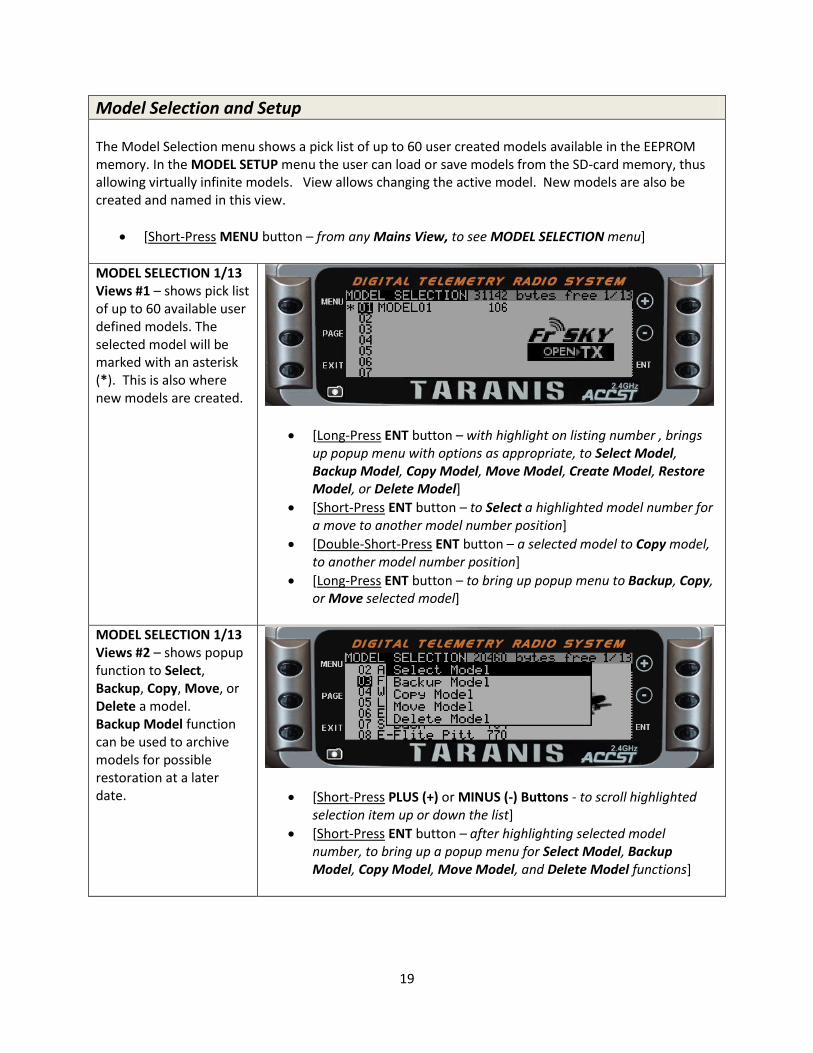
CALIBRATION 7/7 Views #2- shows transmitter gimbal stick positions and prompts to center sticks and sliders.
[Short-Press ENT button – after centering both transmitter gimbal sticks, to proceed with calibration procedure]
CALIBRATION 7/7 Views #3 – shows prompt to move transmitter gimbal sticks and knob potentiometers.
[Short-Press ENT button – after moving transmitter gimbal sticks and knobs fully in both x and y axis]
19
Model Selection and Setup The Model Selection menu shows a pick list of up to 60 user created models available in the EEPROM memory. In the MODEL SETUP menu the user can load or save models from the SD-card memory, thus allowing virtually infinite models. View allows changing the active model. New models are also be created and named in this view.
[Short-Press MENU button – from any Mains View, to see MODEL SELECTION menu]
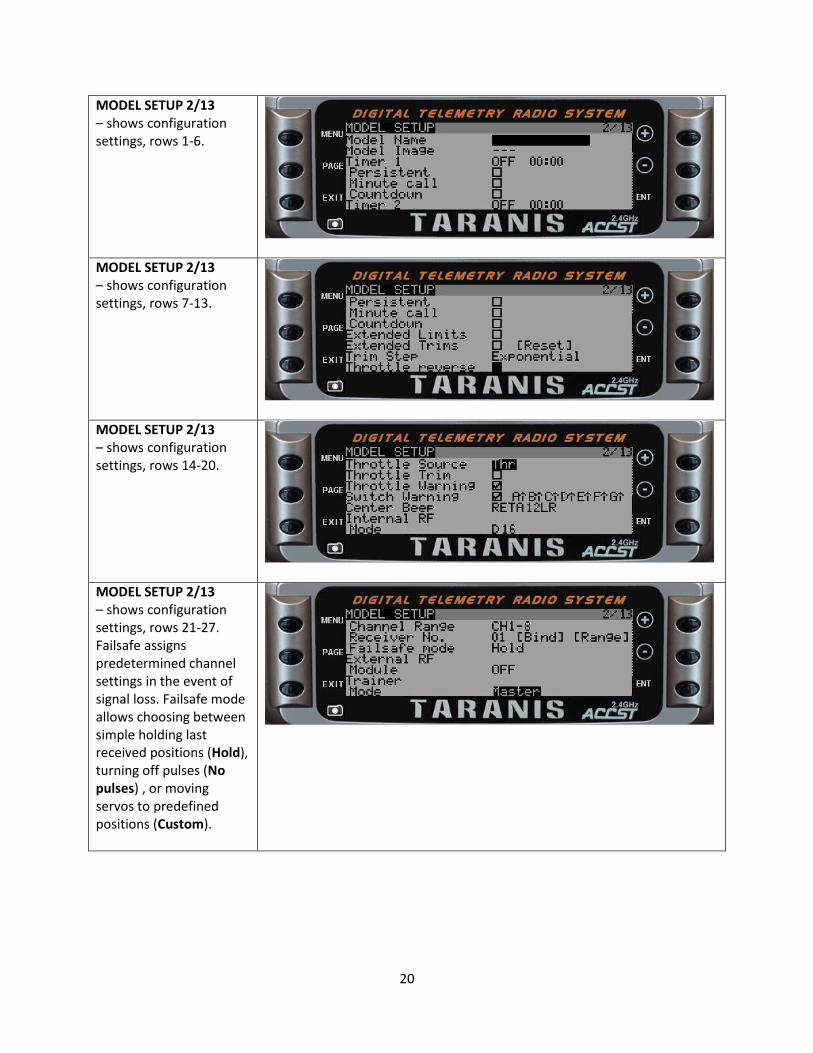
MODEL SELECTION 1/13 Views #1 – shows pick list of up to 60 available user defined models. The selected model will be marked with an asterisk (*). This is also where new models are created.
[Long-Press ENT button – with highlight on listing number , brings up popup menu with options as appropriate, to Select Model, Backup Model, Copy Model, Move Model, Create Model, Restore Model, or Delete Model]
[Short-Press ENT button – to Select a highlighted model number for a move to another model number position]
[Double-Short-Press ENT button – a selected model to Copy model, to another model number position]
[Long-Press ENT button – to bring up popup menu to Backup, Copy, or Move selected model]
MODEL SELECTION 1/13 Views #2 – shows popup function to Select, Backup, Copy, Move, or Delete a model. Backup Model function can be used to archive models for possible restoration at a later date.
[Short-Press PLUS (+) or MINUS (-) Buttons - to scroll highlighted selection item up or down the list]
[Short-Press ENT button – after highlighting selected model number, to bring up a popup menu for Select Model, Backup Model, Copy Model, Move Model, and Delete Model functions]
20
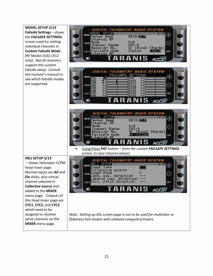
MODEL SETUP 2/13 – shows configuration settings, rows 1-6.
MODEL SETUP 2/13 – shows configuration settings, rows 7-13.
MODEL SETUP 2/13 – shows configuration settings, rows 14-20.
MODEL SETUP 2/13 – shows configuration settings, rows 21-27. Failsafe assigns predetermined channel settings in the event of signal loss. Failsafe mode allows choosing between simple holding last received positions (Hold), turning off pulses (No pulses) , or moving servos to predefined positions (Custom).
21
MODEL SETUP 2/13 Failsafe Settings – shows the FAILSAFE SETTINGS screen used for setting individual channels in Custom Failsafe Mode (RF Modes D16/ LR12 only). Not all receivers support this custom failsafe setup. Consult the receiver’s manual to see which failsafe modes are supported.
[Long-Press ENT button – from the custom FAILSAFE SETTINGS
screen, to save channel values]
HELI SETUP 3/13 – shows helicopter CCPM head mixer page. Normal inputs are Ail and Ele sticks, plus virtual channel selected in Collective source and added to the MIXER menu page. Outputs of this head mixer page are CYC1, CYC2, and CYC3 which need to be assigned to receiver servo channels on the MIXER menu page.
Note: Setting up this screen page is not to be used for multirotor or flybarless heli models with onboard computers/mixers.
22
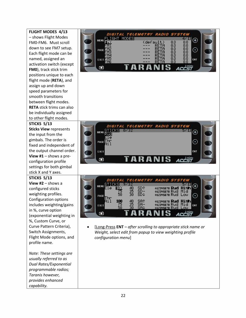
FLIGHT MODES 4/13 – shows Flight Modes FM0-FM6. Must scroll down to see FM7 setup. Each flight mode can be named, assigned an activation switch (except FM0), track stick trim positions unique to each flight mode (RETA), and assign up and down speed parameters for smooth transitions between flight modes. RETA stick trims can also be individually assigned to other flight modes.
STICKS 5/13 Sticks View represents the input from the gimbals. The order is fixed and independent of the output channel order. View #1 – shows a pre-configuration profile settings for both gimbal stick X and Y axes.
STICKS 5/13 View #2 – shows a configured sticks weighting profiles. Configuration options includes weighting/gains in %, curve option (exponential weighting in %, Custom Curve, or Curve Pattern Criteria), Switch Assignments, Flight Mode options, and profile name. Note: These settings are usually referred to as Dual Rates/Exponential programmable radios; Taranis however, provides enhanced capability.
[Long-Press ENT – after scrolling to appropriate stick name or Weight, select edit from popup to view weighting profile configuration menu]
23
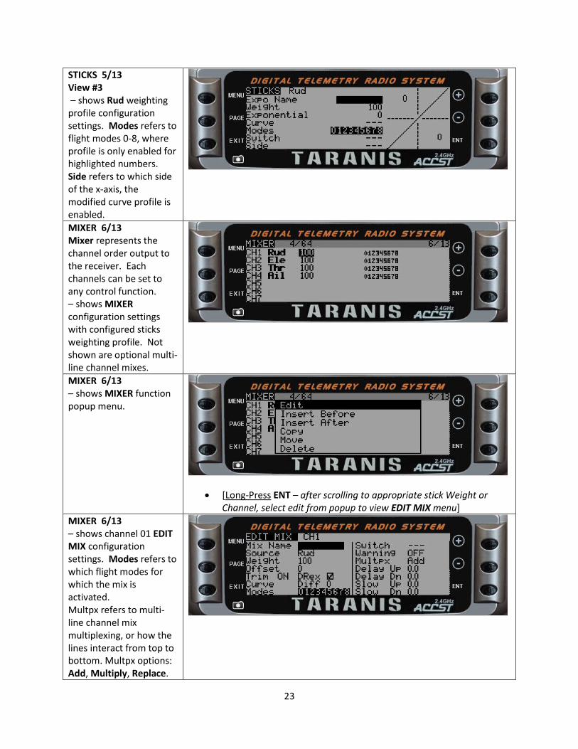
STICKS 5/13 View #3 – shows Rud weighting profile configuration settings. Modes refers to flight modes 0-8, where profile is only enabled for highlighted numbers. Side refers to which side of the x-axis, the modified curve profile is enabled.
MIXER 6/13 Mixer represents the channel order output to the receiver. Each channels can be set to any control function. – shows MIXER configuration settings with configured sticks weighting profile. Not shown are optional multi-line channel mixes.
MIXER 6/13 – shows MIXER function popup menu.
[Long-Press ENT – after scrolling to appropriate stick Weight or Channel, select edit from popup to view EDIT MIX menu]
MIXER 6/13 – shows channel 01 EDIT MIX configuration settings. Modes refers to which flight modes for which the mix is activated. Multpx refers to multi-line channel mix multiplexing, or how the lines interact from top to bottom. Multpx options: Add, Multiply, Replace.
24
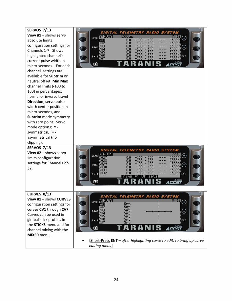
SERVOS 7/13 View #1 – shows servo absolute limits configuration settings for Channels 1-7. Shows highlighted channel’s current pulse width in micro-seconds. For each channel, settings are available for Subtrim or neutral offset, Min Max channel limits (-100 to 100) in percentages, normal or inverse travel Direction, servo pulse width center position in micro-seconds, and Subtrim mode symmetry with zero point. Servo mode options: ^ -symmetrical, = - asymmetrical (no clipping).
SERVOS 7/13 View #2 – shows servo limits configuration settings for Channels 27-32.
CURVES 8/13 View #1 – shows CURVES configuration settings for curves CV1 through CV7. Curves can be used in gimbal stick profiles in the STICKS menu and for channel mixing with the MIXER menu.
[Short-Press ENT – after highlighting curve to edit, to bring up curve editing menu]
25
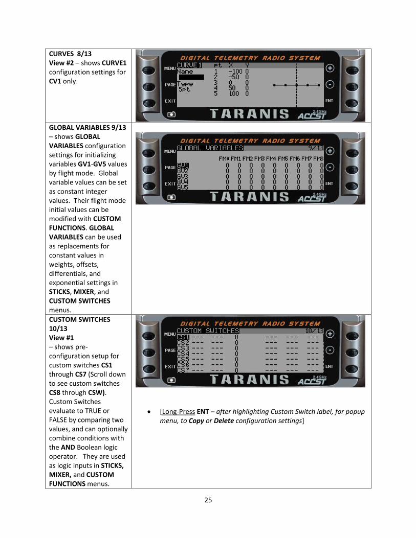
CURVES 8/13 View #2 – shows CURVE1 configuration settings for CV1 only.
GLOBAL VARIABLES 9/13 – shows GLOBAL VARIABLES configuration settings for initializing variables GV1-GV5 values by flight mode. Global variable values can be set as constant integer values. Their flight mode initial values can be modified with CUSTOM FUNCTIONS. GLOBAL VARIABLES can be used as replacements for constant values in weights, offsets, differentials, and exponential settings in STICKS, MIXER, and CUSTOM SWITCHES menus.
CUSTOM SWITCHES 10/13 View #1 – shows pre-configuration setup for custom switches CS1 through CS7 (Scroll down to see custom switches CS8 through CSW). Custom Switches evaluate to TRUE or FALSE by comparing two values, and can optionally combine conditions with the AND Boolean logic operator. They are used as logic inputs in STICKS, MIXER, and CUSTOM FUNCTIONS menus.
[Long-Press ENT – after highlighting Custom Switch label, for popup menu, to Copy or Delete configuration settings]

26
Duration and Delay parameters are provided to add time dependent logic results. A timer function (TIM) can be used to provide timed cycling pulse logic. More complex logic function can be configured by linking one or more custom switches.
CUSTOM SWITCHES 10/13 View #2 - shows a configured screen with several custom switches.
CUSTOM FUNCTIONS 11/13 View #1 – shows pre-configuration setup of custom functions CF1 through CF7 (scroll down to see custom functions CF8 through CF32). Custom Functions are used to assign global variables, toggle switches, sliders, knobs, and custom switches to transmitter hardware features (like starting or stopping a timer, a sound track, or adjust speaker volume). Custom Functions can also be used to adjust global variables.
[Long-Press ENT – when editing switch selection column, to enable/disable toggle mode]
[Long-Press ENT – on a highlighted label for a configured custom function, brings up a popup menu to Copy/Paste/Delete]
27
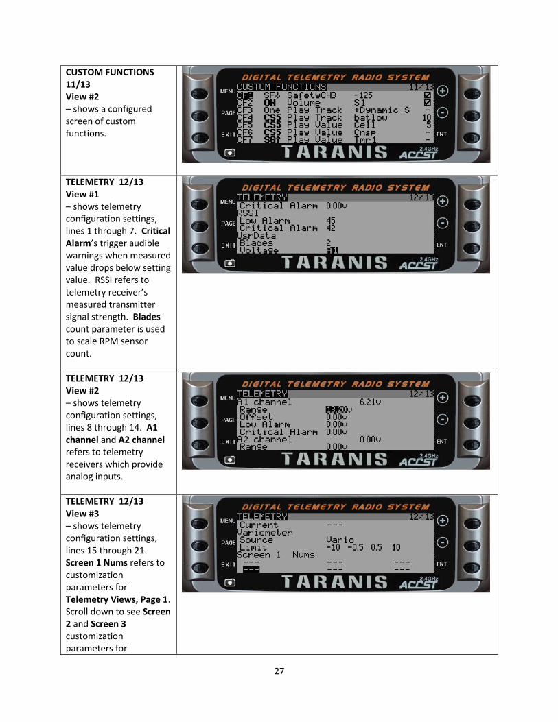
CUSTOM FUNCTIONS 11/13 View #2 – shows a configured screen of custom functions.
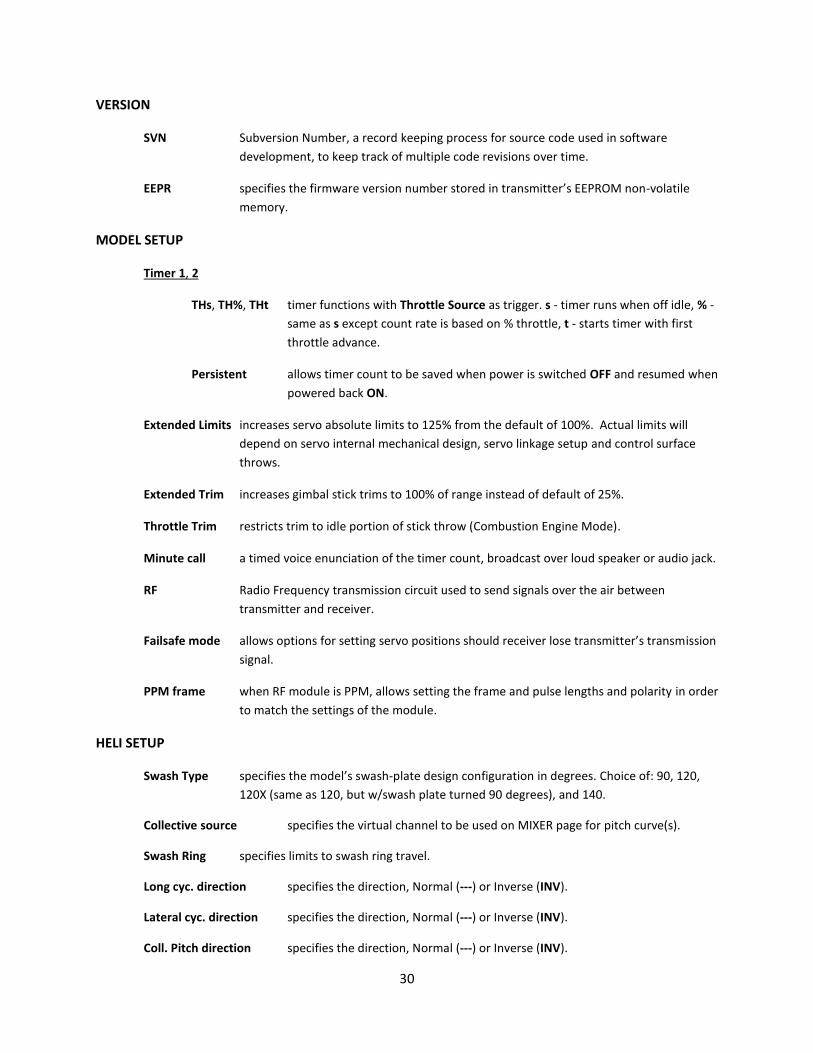
TELEMETRY 12/13 View #1 – shows telemetry configuration settings, lines 1 through 7. Critical Alarm’s trigger audible warnings when measured value drops below setting value. RSSI refers to telemetry receiver’s measured transmitter signal strength. Blades count parameter is used to scale RPM sensor count.
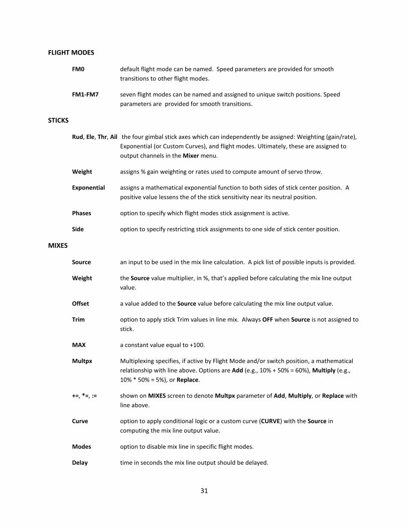
TELEMETRY 12/13 View #2 – shows telemetry configuration settings, lines 8 through 14. A1 channel and A2 channel refers to telemetry receivers which provide analog inputs.
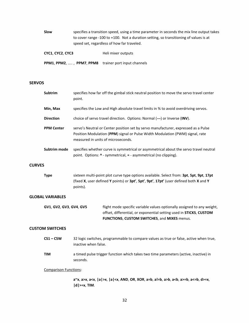
TELEMETRY 12/13 View #3 – shows telemetry configuration settings, lines 15 through 21. Screen 1 Nums refers to customization parameters for Telemetry Views, Page 1. Scroll down to see Screen 2 and Screen 3 customization parameters for

28
Telemetry Views Page #3 thru Telemetry Views page #5. Variometer Source refers to sensor type installed at the receiver.
TEMPLATES 13/13 – shows available model templates pick list.
[Short-Press ENT – after highlighting a listed template, a up popup menu allows replacing the current model’s mixer settings]

29
Glossary of Acronyms, Functions, and Parameter Labels
RADIO SETUP
Sound Mode specifies which sounds are activated. Choice of: All, NoKey (all except button press
beeps), Alarm (alarm only), and Quiet (no sound).
Bg Volume Background music Volume.
Backlight Mode specifies LCD display backlighting wakeup activity. Choice of: OFF, Keys (detect button
press), Controls (gimbal stick/slider/knob/switch), Both (Keys or Controls), or ON
(always on).
Vario Volume Variometer beep volume used to judge changes in altitude.
GPS Global Positioning System a satellite navigation system used to provide location and
time information anywhere on earth.
GPS Timezone specifies Universal Time Coordinated (UTC) Offset for local longitudinal time zone (-12
through +12).
GPS coordinate format specifies HMS or NMEA (National Marine Electronics Association).
FAI disables all telemetry displays, other than RSSI and voltage, to comply with Federation
Aeronautique Internationale (FAI) regulations for contests, championships, and record
setting activities.
SD Card
SD Card flash memory card, SD micro format, typically 2GB capacity is included with Taranis.
BMP Bitmap (BMP) image files in raster image file format (64x32 pixels, 4-bit grayscale) used
to store bitmap digital images
LOGS telemetry data log file(s) stored in comma separated values (csv) file format.
MODELS binary model backup files that have been archived in MODEL SELECTION menu.
SOUNDS mono sound track recordings sampled at up to 32kHz and saved as Waveform Audio File
Format (wav) file format.
TRAINER
Multiplier a value used to align gimbal stick movements of the student’s transmitter (Slave) with
that of the training instructor’s transmitter (Master).
30
VERSION
SVN Subversion Number, a record keeping process for source code used in software
development, to keep track of multiple code revisions over time.
EEPR specifies the firmware version number stored in transmitter’s EEPROM non-volatile
memory.
MODEL SETUP
Timer 1, 2
THs, TH%, THt timer functions with Throttle Source as trigger. s - timer runs when off idle, % -
same as s except count rate is based on % throttle, t - starts timer with first
throttle advance.
Persistent allows timer count to be saved when power is switched OFF and resumed when
powered back ON.
Extended Limits increases servo absolute limits to 125% from the default of 100%. Actual limits will
depend on servo internal mechanical design, servo linkage setup and control surface
throws.
Extended Trim increases gimbal stick trims to 100% of range instead of default of 25%.
Throttle Trim restricts trim to idle portion of stick throw (Combustion Engine Mode).
Minute call a timed voice enunciation of the timer count, broadcast over loud speaker or audio jack.
RF Radio Frequency transmission circuit used to send signals over the air between
transmitter and receiver.
Failsafe mode allows options for setting servo positions should receiver lose transmitter’s transmission
signal.
PPM frame when RF module is PPM, allows setting the frame and pulse lengths and polarity in order
to match the settings of the module.
HELI SETUP
Swash Type specifies the model’s swash-plate design configuration in degrees. Choice of: 90, 120,
120X (same as 120, but w/swash plate turned 90 degrees), and 140.
Collective source specifies the virtual channel to be used on MIXER page for pitch curve(s).
Swash Ring specifies limits to swash ring travel.
Long cyc. direction specifies the direction, Normal (---) or Inverse (INV).
Lateral cyc. direction specifies the direction, Normal (---) or Inverse (INV).
Coll. Pitch direction specifies the direction, Normal (---) or Inverse (INV).
31
FLIGHT MODES
FM0 default flight mode can be named. Speed parameters are provided for smooth
transitions to other flight modes.
FM1-FM7 seven flight modes can be named and assigned to unique switch positions. Speed
parameters are provided for smooth transitions.
STICKS
Rud, Ele, Thr, Ail the four gimbal stick axes which can independently be assigned: Weighting (gain/rate),
Exponential (or Custom Curves), and flight modes. Ultimately, these are assigned to
output channels in the Mixer menu.
Weight assigns % gain weighting or rates used to compute amount of servo throw.
Exponential assigns a mathematical exponential function to both sides of stick center position. A
positive value lessens the of the stick sensitivity near its neutral position.
Phases option to specify which flight modes stick assignment is active.
Side option to specify restricting stick assignments to one side of stick center position.
MIXES
Source an input to be used in the mix line calculation. A pick list of possible inputs is provided.
Weight the Source value multiplier, in %, that’s applied before calculating the mix line output
value.
Offset a value added to the Source value before calculating the mix line output value.
Trim option to apply stick Trim values in line mix. Always OFF when Source is not assigned to
stick.
MAX a constant value equal to +100.
Multpx Multiplexing specifies, if active by Flight Mode and/or switch position, a mathematical
relationship with line above. Options are Add (e.g., 10% + 50% = 60%), Multiply (e.g.,
10% * 50% = 5%), or Replace.
+=, *=, := shown on MIXES screen to denote Multpx parameter of Add, Multiply, or Replace with
line above.
Curve option to apply conditional logic or a custom curve (CURVE) with the Source in
computing the mix line output value.
Modes option to disable mix line in specific flight modes.
Delay time in seconds the mix line output should be delayed.
32
Slow specifies a transition speed, using a time parameter in seconds the mix line output takes
to cover range -100 to +100. Not a duration setting, so transitioning of values is at
speed set, regardless of how far traveled.
CYC1, CYC2, CYC3 Heli mixer outputs
PPM1, PPM2, ….. , PPM7, PPM8 trainer port input channels
SERVOS
Subtrim specifies how far off the gimbal stick neutral position to move the servo travel center
point.
Min, Max specifies the Low and High absolute travel limits in % to avoid overdriving servos.
Direction choice of servo travel direction. Options: Normal (---) or Inverse (INV).
PPM Center servo’s Neutral or Center position set by servo manufacturer, expressed as a Pulse
Position Modulation (PPM) signal or Pulse Width Modulation (PWM) signal, rate
measured in units of microseconds.
Subtrim mode specifies whether curve is symmetrical or asymmetrical about the servo travel neutral
point. Options: ^ - symmetrical, = - asymmetrical (no clipping).
CURVES
Type sixteen multi-point plot curve type options available. Select from: 3pt, 5pt, 9pt, 17pt
(fixed X, user defined Y points) or 3pt’, 5pt’, 9pt’, 17pt’ (user defined both X and Y
points).
GLOBAL VARIABLES
GV1, GV2, GV3, GV4, GV5 flight mode specific variable values optionally assigned to any weight,
offset, differential, or exponential setting used in STICKS, CUSTOM
FUNCTIONS, CUSTOM SWITCHES, and MIXES menus.
CUSTOM SWITCHES
CS1 – CSW 32 logic switches, programmable to compare values as true or false, active when true,
inactive when false.
TIM a timed pulse trigger function which takes two time parameters (active, inactive) in
seconds.
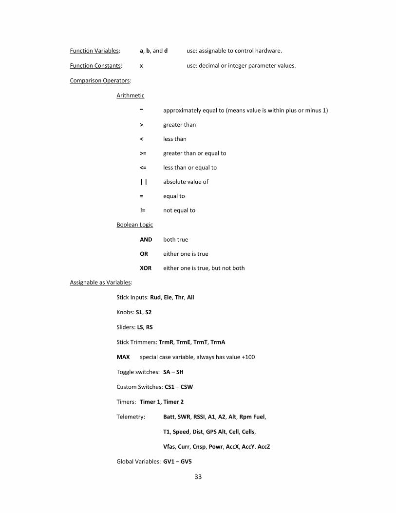
Comparison Functions:
a~x, a>x, a<x, |a|>x, |a|<x, AND, OR, XOR, a=b, a!=b, a>b, a<b, a>=b, a<=b, d>=x,
|d|>=x, TIM.
33
Function Variables: a, b, and d use: assignable to control hardware.
Function Constants: x use: decimal or integer parameter values.
Comparison Operators:
Arithmetic
~ approximately equal to (means value is within plus or minus 1)
> greater than
< less than
>= greater than or equal to
<= less than or equal to
| | absolute value of
= equal to
!= not equal to
Boolean Logic
AND both true
OR either one is true
XOR either one is true, but not both
Assignable as Variables:
Stick Inputs: Rud, Ele, Thr, Ail
Knobs: S1, S2
Sliders: LS, RS
Stick Trimmers: TrmR, TrmE, TrmT, TrmA
MAX special case variable, always has value +100
Toggle switches: SA – SH
Custom Switches: CS1 – CSW
Timers: Timer 1, Timer 2
Telemetry: Batt, SWR, RSSI, A1, A2, Alt, Rpm Fuel,
T1, Speed, Dist, GPS Alt, Cell, Cells,
Vfas, Curr, Cnsp, Powr, AccX, AccY, AccZ
Global Variables: GV1 – GV5
34
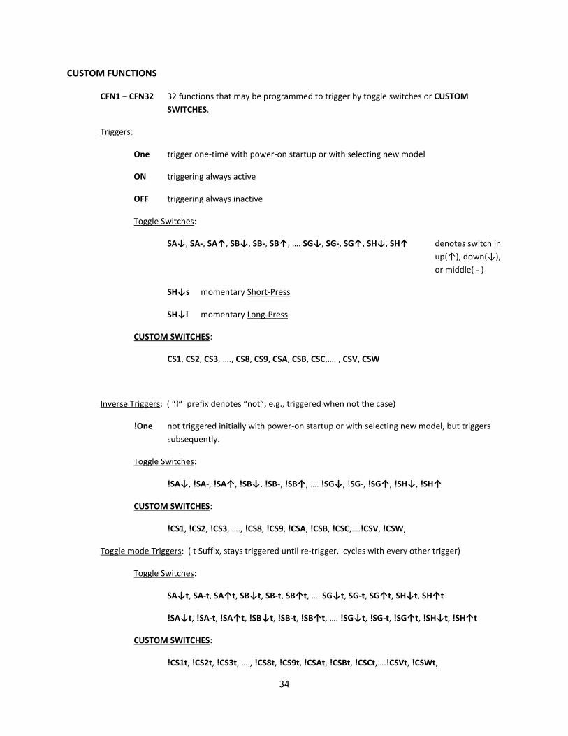
CUSTOM FUNCTIONS
CFN1 – CFN32 32 functions that may be programmed to trigger by toggle switches or CUSTOM
SWITCHES.
Triggers:
One trigger one-time with power-on startup or with selecting new model
ON triggering always active
OFF triggering always inactive
Toggle Switches:
SA↓, SA-, SA↑, SB↓, SB-, SB↑, …. SG↓, SG-, SG↑, SH↓, SH↑ denotes switch in
up(↑), down(↓),
or middle( - )
SH↓s momentary Short-Press
SH↓l momentary Long-Press
CUSTOM SWITCHES:
CS1, CS2, CS3, …., CS8, CS9, CSA, CSB, CSC,…. , CSV, CSW
Inverse Triggers: ( “!” prefix denotes “not”, e.g., triggered when not the case)
!One not triggered initially with power-on startup or with selecting new model, but triggers
subsequently.
Toggle Switches:
!SA↓, !SA-, !SA↑, !SB↓, !SB-, !SB↑, …. !SG↓, !SG-, !SG↑, !SH↓, !SH↑
CUSTOM SWITCHES:
!CS1, !CS2, !CS3, …., !CS8, !CS9, !CSA, !CSB, !CSC,….!CSV, !CSW,
Toggle mode Triggers: ( t Suffix, stays triggered until re-trigger, cycles with every other trigger)
Toggle Switches:
SA↓t, SA-t, SA↑t, SB↓t, SB-t, SB↑t, …. SG↓t, SG-t, SG↑t, SH↓t, SH↑t
!SA↓t, !SA-t, !SA↑t, !SB↓t, !SB-t, !SB↑t, …. !SG↓t, !SG-t, !SG↑t, !SH↓t, !SH↑t
CUSTOM SWITCHES:
!CS1t, !CS2t, !CS3t, …., !CS8t, !CS9t, !CSAt, !CSBt, !CSCt,….!CSVt, !CSWt,

35
Functions
Channel Safety: (forces specific channel output to a specified value)
Safety CH01, Safety CH02,… Safety CH15, Safety CH16
Trainer enables Trainer Mode for RUD, ELE, THR, and AIL globally.
Trainer RUD, Trainer ELE, Trainer THR, Trainer AIL enables Trainer Mode individually.
Instant Trim adds current stick positions to respective stick trims.
Play Sound plays a tone from available list.
Reset resets the selected item. Options: Timer 1, Timer 2, Telemetry, All (Both Timers
& Telemetry).
Vario turns on variometer sounds to speaker or audio jack.
Play Track plays a sound recording file located on the micro SD card.
Play Value speaks the current selected value over the speaker or audio jack.
Start Logs starts recording Telemetry data to micro SD card.
Volume adjusts audio volume using selected source parameter.
Backlight enables LCD backlight lighting.
BgMusic, BgMusic || enables and pauses background music playback.
Adjust GV1, Adjust GV2, ….., Adjust GV5 sets value of specified global variable to a fixed
value, source value, increments value, or to that of
another global variable.
TELEMETRY
Tmr1,Tmr2 two timers with functions set in MODEL SETUP menu.
A1, A2 analog input channels on compatible telemetry receivers.
Batt displays the transmitter’s operating voltage.
SWR measure of transmitter antenna quality. Reading below 51 is normal.
RSSI Received Signal Strength Indication (RSSI) value used to monitor acceptable signal
strength or distance.
Alt variometer altitude reading above ground level.
Rpm RPM reading.
Fuel fuel level.
36
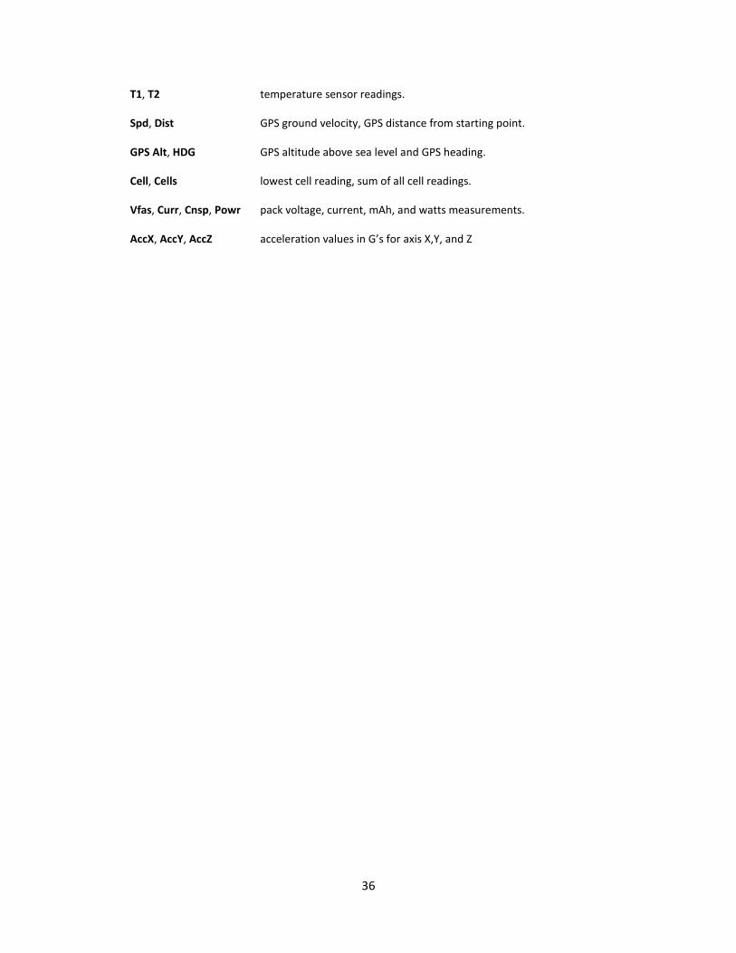
T1, T2 temperature sensor readings.
Spd, Dist GPS ground velocity, GPS distance from starting point.
GPS Alt, HDG GPS altitude above sea level and GPS heading.
Cell, Cells lowest cell reading, sum of all cell readings.
Vfas, Curr, Cnsp, Powr pack voltage, current, mAh, and watts measurements.
AccX, AccY, AccZ acceleration values in G’s for axis X,Y, and Z

37
Screen Mapping Diagram
This chart shows a detailed layout of the various information screens and menus.
Splash Screen
Throttle Warning
Switch Warning
Switch & Gimbal Positions
Physical & Custom Switch Positions
TelemetryGPS Position and Min
RSSI
TelemetryA1 A2 Alarms
TelemetryValues Bars/Nums Custom Screens (3)
RADIO SETUP 1/7
SD CARD 2/7
TRAINER 3/7
VERSION 4/7
SWITCH TEST 5/7
ANALOG INPUTS 6/7
CALIBRATION 7/7
MODEL SELECTION 1/13
MODEL SETUP 2/13
HELI SETUP 3/13
FLIGHT MODES 4/13
STICKS 5/13 EDIT STICK PROFILE
MIXER 6/13 EDIT MIX
SERVOS 7/13
CURVES 8/13 EDIT CURVE PROFILE
GLOBAL VARIABLES 9/13
CUSTOM SWITCHES 10/13
CUSTOM FUNCTIONS 11/13
TELEMETRY 12/13
TEMPLATES 13/13
Channel Monitor
Model Selection & SetupGeneral Radio Settings
Main Views
Telemetry Views
Power On Startup
Display Screens Navigation Mapping
CUSTOM FAILSAFE SETUP
38
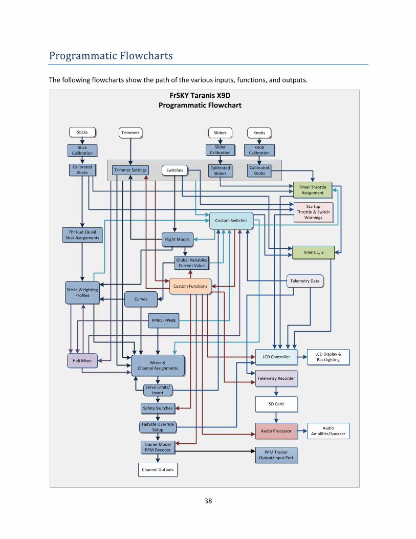
Programmatic Flowcharts
The following flowcharts show the path of the various inputs, functions, and outputs.
Stick Calibration
Mixer &Channel Assignments
FrSKY Taranis X9DProgrammatic Flowchart
Calibrated Sliders
CalibratedKnobs
Trimmers
Servo Limits/Invert
Safety Switches
Custom Functions
Custom Switches
Heli Mixer
Channel Outputs
Flight Modes
Curves
Timers 1, 2
Audio Processor
SD Card
AudioAmplifier/Speaker
Telemetry Recorder
FailSafe Override Setup
Sticks Weighting Profiles
Timer Throttle Assignment
LCD ControllerLCD Display & Backlighting
Thr Rud Ele AilStick Assignments
Trimmer Settings
PPM TrainerOutput/Input Port
Trainer Mode/PPM Decoder
Telemetry Data
Global Variables Current Value
PPM1-PPM8
Sticks
Slider Calibration
Knob Calibration
Sliders Knobs
Calibrated Sticks
StartupThrottle & Switch
Warnings
Switches

39
This is a simplified version of the previous chart. Advanced functions are removed to reduce complexity.
Stick Calibration
Mixer &Channel Assignments
FrSKY Taranis X9DProgrammatic Flowchart
Calibrated Sliders
CalibratedKnobs
Trimmers
Servo Limits/Invert
Safety Switches
Custom Functions
Custom Switches
Channel Outputs
Flight Modes
Curves
FailSafe Override Setup
Sticks Weighting Profiles
Thr Rud Ele AilStick Assignments
Trimmer Settings
PPM TrainerOutput/Input Port
Trainer Mode/PPM Decoder
Global Variables Current Value
PPM1-PPM8
Sticks
Slider Calibration
Knob Calibration
Sliders Knobs
Calibrated Sticks Switches
Basic – Less Heli Mixer, Timers, Warnings, Telemetry, Audio, LCD Display, & SD Card
40
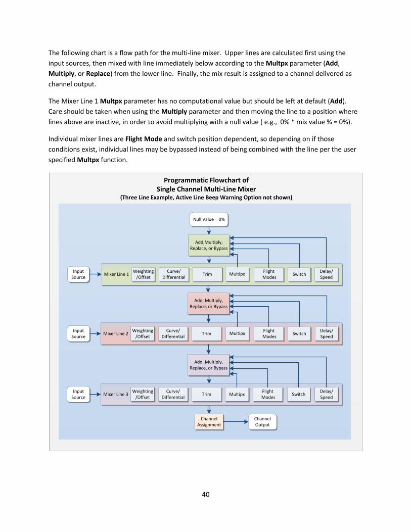
The following chart is a flow path for the multi-line mixer. Upper lines are calculated first using the
input sources, then mixed with line immediately below according to the Multpx parameter (Add,
Multiply, or Replace) from the lower line. Finally, the mix result is assigned to a channel delivered as
channel output.
The Mixer Line 1 Multpx parameter has no computational value but should be left at default (Add).
Care should be taken when using the Multiply parameter and then moving the line to a position where
lines above are inactive, in order to avoid multiplying with a null value ( e.g., 0% * mix value % = 0%).
Individual mixer lines are Flight Mode and switch position dependent, so depending on if those
conditions exist, individual lines may be bypassed instead of being combined with the line per the user
specified Multpx function.
Channel Assignment
Mixer Line 2
Add, Multiply,Replace, or Bypass
Programmatic Flowchart ofSingle Channel Multi-Line Mixer
(Three Line Example, Active Line Beep Warning Option not shown)
Add, Multiply,Replace, or Bypass
Input Source
Input Source
Input Source
Weighting/Offset
Delay/Speed
Curve/Differential
Flight Modes
SwitchTrim
Mixer Line 1Weighting
/OffsetDelay/Speed
Curve/Differential
Flight Modes
SwitchTrim
Mixer Line 3Weighting
/OffsetDelay/Speed
Curve/Differential
Flight Modes
SwitchTrim
Channel Output
Add,Multiply,Replace, or Bypass
Null Value = 0%
Multipx
Multipx
Multipx
41
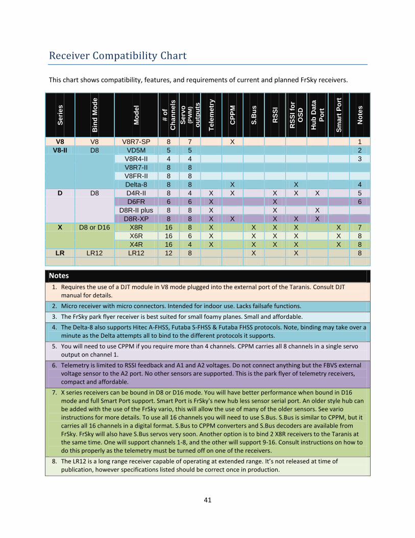
Receiver Compatibility Chart
This chart shows compatibility, features, and requirements of current and planned FrSky receivers.
Seri
es
Bin
d M
od
e
Mo
del
# o
f
Ch
an
nels
Serv
o
(PW
M)
ou
tpu
ts
Tele
metr
y
CP
PM
S.B
us
RS
SI
RS
SI fo
r
OS
D
Hu
b D
ata
Po
rt
Sm
art
Po
rt
No
tes
V8 V8 V8R7-SP 8 7 X 1
V8-II D8 VD5M 5 5 2
V8R4-II 4 4 3
V8R7-II 8 8
V8FR-II 8 8
Delta-8 8 8 X X 4
D D8 D4R-II 8 4 X X X X X 5
D6FR 6 6 X X 6
D8R-II plus 8 8 X X X
D8R-XP 8 8 X X X X X
X D8 or D16 X8R 16 8 X X X X X 7
X6R 16 6 X X X X X 8
X4R 16 4 X X X X X 8
LR LR12 LR12 12 8 X X 8
Notes
1. Requires the use of a DJT module in V8 mode plugged into the external port of the Taranis. Consult DJT manual for details.
2. Micro receiver with micro connectors. Intended for indoor use. Lacks failsafe functions.
3. The FrSky park flyer receiver is best suited for small foamy planes. Small and affordable.
4. The Delta-8 also supports Hitec A-FHSS, Futaba S-FHSS & Futaba FHSS protocols. Note, binding may take over a minute as the Delta attempts all to bind to the different protocols it supports.
5. You will need to use CPPM if you require more than 4 channels. CPPM carries all 8 channels in a single servo output on channel 1.
6. Telemetry is limited to RSSI feedback and A1 and A2 voltages. Do not connect anything but the FBVS external voltage sensor to the A2 port. No other sensors are supported. This is the park flyer of telemetry receivers, compact and affordable.
7. X series receivers can be bound in D8 or D16 mode. You will have better performance when bound in D16 mode and full Smart Port support. Smart Port is FrSky's new hub less sensor serial port. An older style hub can be added with the use of the FrSky vario, this will allow the use of many of the older sensors. See vario instructions for more details. To use all 16 channels you will need to use S.Bus. S.Bus is similar to CPPM, but it carries all 16 channels in a digital format. S.Bus to CPPM converters and S.Bus decoders are available from FrSky. FrSky will also have S.Bus servos very soon. Another option is to bind 2 X8R receivers to the Taranis at the same time. One will support channels 1-8, and the other will support 9-16. Consult instructions on how to do this properly as the telemetry must be turned off on one of the receivers.
8. The LR12 is a long range receiver capable of operating at extended range. It’s not released at time of publication, however specifications listed should be correct once in production.