quick start guide - hunter douglas window fashions … ac... · getting started 1 description the...
TRANSCRIPT

Quick Start Guide
AC MotorsPowerView™ Motorization

CONTENTS
© 2016 Hunter Douglas. All rights reserved. All trademarks used herein are the property of Hunter Douglas or their respective owners.
Questions?
Call Hunter Douglas Consumer Support at 1-888-501-8364.
GETTING STARTEDDescription ................................................................................................................................................................1Key Components .......................................................................................................................................................1PowerView Instructional Guides ..............................................................................................................................1Product View .............................................................................................................................................................1
PROGRAMMINGProgramming Overview .............................................................................................................................................2STEP 1 — Initial Setup .............................................................................................................................................2STEP 2 — Join a Shade to a Group .........................................................................................................................2STEP 3 — Reverse the Motor Direction (If Necessary) ...........................................................................................3STEP 4 — Set the Motor Upper Limit ......................................................................................................................3STEP 5 — Set the Motor Lower Limit ......................................................................................................................4STEP 6 — Set a FAVORITE Position (Optional) ........................................................................................................4STEP 7 — Pairing a PowerView™ Hub to a Remote Created PowerView Shade Network (Optional) ....................5STEP 8 — PowerView App and PowerView Hub (Optional) ....................................................................................5STEP 9 — Test the Motors and PowerView Shade Network ..................................................................................5
APPENDIX AClear Motor Limits ....................................................................................................................................................6Remove a Shade from a Group .................................................................................................................................6Reset Shade Programming .......................................................................................................................................7Reset to Factory Default ...........................................................................................................................................7Control the Motor with Dry Contacts — M40 Series motor only ............................................................................7
APPENDIX BMotor Cabling Options ..............................................................................................................................................8Motor Specifications ................................................................................................................................................9
SAFETY ....................................................................................................................................................................10
DECLARATIONS ..................................................................................................................................................11

GETTING STARTED
1
DESCRIPTIONThe PowerView™ AC motor is designed to operate Hunter Douglas Alustra® Woven Textures® & Screen Shades, Designer Roller Shades, and Designer Screen Shades. The PowerView AC motor works in combination with the PowerView Pebble™ Remote, PowerView Hub, and PowerView App for radio frequency (RF) control of a single shade or multiple networked shades.
The current version of the PowerView AC motor does not fully support tilt products.
WARNING: Factory fresh motors do not have default limits set. Limits must be set to enable normal operation. If operated without limits, the shade could be damaged by rolling over the top or wrapping backwards on the roller.
KEY COMPONENTSThe following items are required for single shade or multiple shade setup.
■■ PowerView AC motor(s) with roller shade(s)
■■ PowerView Pebble Remote or PowerView Surface Remote
The following items are optional.
■■ PowerView Hub
■■ PowerView App
■■ PowerView Repeater
POWERVIEW INSTRUCTIONAL GUIDESPlease see the PowerView Instructional Guides and FAQs at the following URL:
www.hunterdouglas.com/operating-systems/powerview-motorization/support
A user/installer must be familiar with the setup and operation of the following:
■■ PowerView Pebble Remote or PowerView Surface Remote
■■ PowerView Hub
■■ PowerView Repeater
■■ PowerView App
PRODUCT VIEW
CAUTION: Do not damage the RF antenna. For best RF performance, the antenna should maintain as much separation from a conductive surface as possible.
Manual Control Button
M40 Series
Dry ContactInput
RF Antenna
Manual Control Button
RF Antenna
M50 Series

PROGRAMMING
2
PROGRAMMING OVERVIEWTo program your PowerView™ AC motor and roller shade, you will need to perform the following 9 steps:
STEP 1: Initial Setup
STEP 2: Join a Shade to a Group
STEP 3: Reverse the Motor Direction (If Necessary)
STEP 4: Set the Motor Upper Limit
STEP 5: Set the Motor Lower Limit
STEP 6: Set a FAVORITE Position (Optional)
STEP 7: Pairing a PowerView Hub to a Remote Created PowerView Shade Network (Optional)
STEP 8: PowerView App and PowerView Hub (Optional)
STEP 9: Test the Motors and PowerView Shade Network
STEP 1 — INITIAL SETUP■■ Mount the factory fresh AC motor and shade into an appropriate
window opening.
■■ Apply power to the AC motor (120V~ or 230V~).
■■ On a factory fresh PowerView Remote, install batteries.
STEP 2 — JOIN A SHADE TO A GROUP■■ Remote: press and hold STOP for 4 seconds to put the
remote into program mode.
■➤ The backlit buttons on the remote will flash to indicate it is in program mode.
■■ Remote: press and release the desired GROUP number (1 – 6).
■➤ The backlit GROUP number will flash to show it is selected.
■■ Motor: press and hold the manual control button located on the motor head.
■■ Remote: while continuing to press the manual control button, press and release OPEN on the remote.
■➤ The shade will move twice to indicate it has joined the group.
■■ Motor: release the manual control button.
■■ Remote: press and hold STOP for 4 seconds to exit program mode.
■➤ The lights will stop flashing.
WARNING: The AC motor will not operate normally until limits are set (Step 4 and Step 5).
One GROUP numbermust be selected.

PROGRAMMING
3
STEP 3 — REVERSE THE MOTOR DIRECTION (IF NECESSARY)IMPORTANT: Be sure no end limits are set on the motor. If one or both limits are set, you cannot change the motor direction. See Appendix A for instructions to clear limits.
■■ Remote: deselect all GROUP numbers.
■■ Motor: press and hold the manual control button located on the motor head.
■■ Remote: while continuing to press the manual control button, press and release STOP on the remote.
■➤ The shade will move twice to indicate it has reversed motor direction.
NOTE: If end limits were already set, the motor will not move, indicating the motor direction did not change.
NOTE: Verify that all GROUP lights are turned off on the remote, clear both limits, and try again.
■■ Motor: release the manual control button.
STEP 4 — SET THE MOTOR UPPER LIMITNOTE: When end limits are not set, the motor responds to OPEN or CLOSE on the remote with single, small movements.
■■ Move the shade to the desired upper limit.
■➤ On the motor, use the manual control button or dry contact input (M40 Series only).
■➤ On the remote, use the OPEN, CLOSE, LEFT ARROW, or RIGHT ARROW buttons.
■■ Remote: press and hold STOP for 4 seconds to put the remote into program mode.
■➤ The backlit buttons on the remote will flash to indicate it is in program mode.
■■ Remote: deselect all GROUP numbers.
■■ Motor: press and hold the manual control button located on the motor head.
■■ Remote: while continuing to press the manual control button, press and release OPEN on the remote.
■➤ The shade will move twice to indicate the upper limit is set.
■■ Motor: release the manual control button.
■■ Remote: press and hold STOP for 4 seconds to exit program mode.
■➤ The lights will stop flashing.
IMPORTANT: Verify that the upper limit is set. If not, deselect all GROUP numbers and repeat Step 4.
Deselect all GROUPnumbers.
Deselect all GROUPnumbers.

PROGRAMMING
4
STEP 5 — SET THE MOTOR LOWER LIMITNOTE: When end limits are not set, the motor responds to OPEN or CLOSE on the remote with single, small movements.
■■ Move the shade to the desired lower limit.
■➤ On the motor, use the manual control button or dry contact input (M40 Series only).
■➤ On the remote, use the OPEN, CLOSE, LEFT ARROW, or RIGHT ARROW buttons.
■■ Remote: press and hold STOP for 4 seconds to put the remote into program mode.
■➤ The backlit buttons on the remote will flash to indicate it is in program mode.
■■ Remote: deselect all GROUP numbers.
■■ Motor: press and hold the manual control button located on the motor head.
■■ Remote: while continuing to press the manual control button, press and release CLOSE on the remote.
■➤ The shade will move twice to indicate the lower limit is set.
■■ Motor: release the manual control button.
■■ Remote: press and hold STOP for 4 seconds to exit program mode.
■➤ The lights will stop flashing.
IMPORTANT: Verify that the lower limit is set. If not, deselect all GROUP numbers and repeat Step 5.
STEP 6 — SET A FAVORITE POSITION (OPTIONAL)NOTE: After the upper and lower limits are set, the motor will have one FAVORITE position, which is set at 50% open by default. Setting a new FAVORITE position overwrites any previous setting.
■■ Move the motor open or close to the desired position.
■■ Remote: press and hold STOP for 4 seconds to put the remote into program mode.
■➤ The backlit buttons on the remote will flash to indicate it is in program mode.
■■ Remote: deselect all GROUP numbers.
■■ Motor: press and hold the manual control button located on the motor head.
■■ Remote: while continuing to press the manual control button, press and release FAVORITE on the remote.
■➤ The shade will move twice to indicate it has set this shade position as your FAVORITE.
■■ Motor: release the manual control button.
■■ Remote: press and hold STOP for 4 seconds to exit program mode.
■➤ The lights will stop flashing.
IMPORTANT: Verify that the FAVORITE position is set at the desired position.
Deselect all GROUPnumbers.
Deselect all GROUPnumbers.

PROGRAMMING
5
STEP 7 — PAIRING A POWERVIEW™ HUB TO A REMOTE CREATED POWERVIEW SHADE NETWORK (OPTIONAL)See the Quick-Start Manuals and Short Topic Videos on the Hunter Douglas PowerView™ Motorization Support web page: www.hunterdouglas.com/operating-systems/powerview-motorization/support
STEP 8 — POWERVIEW APP AND POWERVIEW HUB (OPTIONAL)See the Quick-Start Manuals and Short Topic Videos on the Hunter Douglas PowerView Motorization Support web page: www.hunterdouglas.com/operating-systems/powerview-motorization/support
STEP 9 — TEST THE MOTORS AND POWERVIEW SHADE NETWORKUse the remote or PowerView App to verify the following settings for all shades in the PowerView Shade Network.
■■ Verify each shade is joined to the correct GROUP number.
■➤ Press ALL to move all shades.
■➤ Press GROUP 1 – 6 to select specific shades to operate.
■■ Verify that the motor direction is correctly set for each shade.
■➤ Press ALL, then press OPEN on the remote.
■➤ All shades should move in the up direction.
■■ Verify that the upper limit is correctly set for each shade.
■➤ Press ALL, then press OPEN on the remote.
■➤ All shades should stop at the correct upper limit.
■■ Verify that the lower limit is correctly set for each shade.
■➤ Press ALL, then press CLOSE on the remote.
■➤ All shades should stop at the correct lower limit.
■■ Verify that the FAVORITE position is correctly set for each shade.
■➤ Press ALL, then press FAVORITE on the remote.
■➤ All shades should stop at the correct FAVORITE position.

APPENDIX A
6
CLEAR MOTOR LIMITS
Clear Upper Limit■■ Remote: deselect all GROUP numbers.
■■ Motor: press and hold the manual control button located on the motor head.
■■ Remote: while continuing to press the manual control button, press and release OPEN on the remote.
■➤ The shade will move twice to indicate the upper limit is cleared.
■■ Motor: Release the manual control button.
Clear Lower Limit■■ Remote: deselect all GROUP numbers.
■■ Motor: press and hold the manual control button located on the motor head.
■■ Remote: while continuing to press the manual control button, press and release CLOSE on the remote.
■➤ The shade will move twice to indicate the lower limit is cleared.
■■ Motor: Release the manual control button.
REMOVE A SHADE FROM A GROUPNOTE: Only one GROUP number can be removed at a time.
■■ Remote: press and hold STOP for 4 seconds to put the remote into program mode.
■➤ The backlit buttons on the remote will flash to indicate it is in program mode.
■■ Remote: press the desired GROUP number (1 – 6).
■➤ The backlit GROUP number will flash to show it is selected.
■■ Motor: press and hold the manual control button located on the motor head.
■■ Remote: while continuing to press the manual control button, press and release CLOSE on the remote.
■➤ The shade will move twice to indicate it has been removed from the group.
■■ Motor: Release the manual control button.
■■ Remote: Press and hold STOP for 4 seconds to exit program mode.
■➤ The lights will stop flashing.
Deselect all GROUPnumbers.
Deselect all GROUPnumbers.
One GROUP numbermust be selected.
APPENDIX A
7
RESET SHADE NETWORK PROGRAMMINGThe shade network programming reset erases all remote GROUP assignment programming stored in the shade. The reset will also remove the shade from its current PowerView™ Shade Network, preventing any input device from operating the shade. The primary use is during installation to correct GROUP and Network assignments. This reset does not affect motor limits, motor direction, or the FAVORITE position.
■■ Motor: press and hold the manual control button located on the motor head for 12 seconds.
■➤ The shade will move twice after 6 seconds, then again after 12 seconds.
■■ Motor: Release the manual control button.
Refer to “JOIN A SHADE TO A GROUP” on page 2 to program the shade into a group.
RESET TO FACTORY DEFAULTThe factory default reset erases all information stored in a shade motor. The motor is returned to its factory default settings of no network programming, no limits, and the motor direction is reset. The default FAVORITE position will be at 50% after limits are set.
■■ Motor: press and hold the manual control button located on the motor head for 18 seconds.
■➤ The shade will move twice after 6 seconds, then again after 12 seconds, and then again after 18 seconds.
■■ Motor: Release the manual control button.
Refer to “JOIN A SHADE TO A GROUP” on page 2 to program the shade into a group, then reverse motor direction (if necessary), set limits, and set a new FAVORITE position (optional).
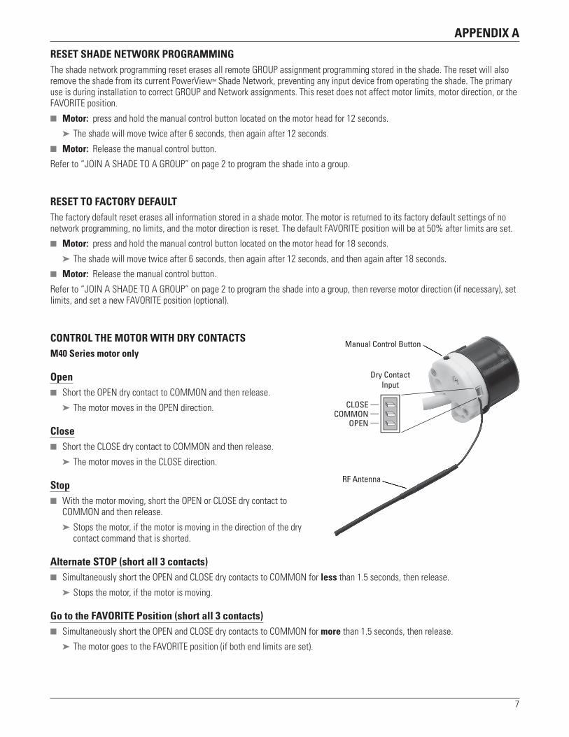
CONTROL THE MOTOR WITH DRY CONTACTSM40 Series motor only
Open■■ Short the OPEN dry contact to COMMON and then release.
■➤ The motor moves in the OPEN direction.
Close■■ Short the CLOSE dry contact to COMMON and then release.
■➤ The motor moves in the CLOSE direction.
Stop■■ With the motor moving, short the OPEN or CLOSE dry contact to
COMMON and then release.
■➤ Stops the motor, if the motor is moving in the direction of the dry contact command that is shorted.
Alternate STOP (short all 3 contacts)■■ Simultaneously short the OPEN and CLOSE dry contacts to COMMON for less than 1.5 seconds, then release.
■➤ Stops the motor, if the motor is moving.
Go to the FAVORITE Position (short all 3 contacts)■■ Simultaneously short the OPEN and CLOSE dry contacts to COMMON for more than 1.5 seconds, then release.
■➤ The motor goes to the FAVORITE position (if both end limits are set).
Manual Control Button
Dry ContactInput
RF Antenna
Manual Control Button
Dry ContactInput
RF Antenna
CLOSECOMMON
OPEN

APPENDIX B
8
MOTOR CABLING OPTIONSThe PowerView™ AC motor is designed to be used with roller shades and has the following cable options available.
Motor Model CablingM40 Series M40PV330
M40PV334
M40PV430
M40PV620
M40PV624
M40PV915
Blunt end cord: to be wired according to local electrical codes.
Pigtail cord: connects to a detachable power cord (U.S. plug end only) for use in a standard 120V wall outlet.
M50 Series M50PV525
M50PV530
M50PV626
M50PV634
M50PV674
M50PV790
M50PV926
M50PV934
M50PV1016
M50PV1017
M50PV1234
M50PV1530
M50PV2017
M50PV2521
M50PV3017
M50PV3521
M50PV4016
M50PV4017
M50PV5014
Blunt end cord: to be wired according to local electrical codes.

APPENDIX B
9
MOTOR SPECIFICATIONSAll motors are available as either 120V~ or 230V~.
CAUTION: Never exceed the lift capacity (Nm) in the specification table below.
IMPORTANT: A motor that is cool may run for up to 4 minutes continuously before it overheats. If the motor is run continuously for more than 4 minutes, the motor may overheat. A motor that overheats will stop moving and will not respond to move commands while it cools. The motor will cool down to operating temperature after 10-15 minutes, depending on ambient temperature and ventilation.
Motor Model TorqueNm
SpeedRPM
Full LoadAmperes
M40 Series M40PV330 3 30 0.40
M40PV334 3 34 0.90
M40PV430 4 30 0.90
M40PV620 6 20 0.60
M40PV624 6 24 1.1
M40PV915 9 15 1.1
M50 Series M50PV525 5 25 0.90
M50PV530 5 30 0.70
M50PV626 6 26 0.6
M50PV634 6 34 0.6
M50PV674 6 74 1.2
M50PV790 7 90 1.2
M50PV926 9 26 0.8
M50PV934 9 34 0.8
M50PV1016 10 16 0.7
M50PV1017 10 17 0.7
M50PV1234 12 34 1.1
M50PV1530 15 30 1.1
M50PV2017 20 17 0.8
M50PV2521 25 21 0.8
M50PV3017 30 17 1.2
M50PV3521 35 21 1.2
M50PV4016 40 16 1.5
M50PV4017 40 17 1.8
M50PV5014 50 14 1.5

SAFETY
10
WARNING: Prior to installation inspect all parts for damage or missing components.
WARNING: To Reduce the Risk Of Fire, Electric Shock, Or Injury To Persons, Installation Work And Electrical Wiring Must Be Done By Qualified Person(s) In Accordance With All Applicable Codes And Standards.
WARNING: Never install this product with power connected. DISCONNECT FROM POWER SUPPLY before installing or adding accessories to this device.
WARNING: Important safety instructions. It is important for the safety of persons to follow these instructions. Save these instructions. Frequently examine the installation for imbalance and signs of wear or damage to cables and springs. Do not use if repair or adjustment is necessary.
■■ Do not allow children to play with fixed controls. Keep remote controls away from children. Children should be supervised to ensure that they do not play with the appliance.
■■ The supplied UL rated grounding power cord on models M40PV330 / M40PV334 / M40PV430 / M40PV620 / M40PV624 / M40PV915, if lost or broken, shall be only replaced with an identical power cord. A replacement power cord is available from the distributor or manufacturer.
■■ The power cord must be properly plugged into the electrical outlet and the proper motor model. Loose attachment can cause arcing and can result in failure. Any improper use or misuse can result in electrical shock causing injury to the person or persons.
■■ As with any 120V~ or 230V~ electrical appliance, care must be taken when handling. To reduce the risk of electric shock, this equipment has a grounding type plug that has a third (grounding) pin. Motor models M40PV330 / M40PV334 / M40PV430 / M40PV620 / M40PV624 / M40PV915 are supplied with UL rated grounding power cords that have a grounding pin which shall not be altered or removed. This plug will only fit into a grounding type outlet. If the plug does not fit into the outlet, contact a qualified electrician to install the proper outlet. Do not change the plug in any way.
■■ Use appropriate Class 2 wiring whenever installing dry contact cabling with motor models M40PV330 / M40PV334 / M40PV430 / M40PV620 / M40PV624 / M40PV915.
■■ If this device is installed in the presence of strong Radio Frequency (RF) signals (such as near RF transmitters) loss of functionality may occur.
■■ Changes or modifications not expressly approved by the party responsible for compliance could void the user’s authority to operate this equipment.
■■ If used in an area susceptible to lightning strikes or power surges, surge protectors should be used. Otherwise, unplug this operator and accessories during lightning storms.
■■ Motors are not rated for exterior use. Water can cause shorting and result in electrical shock.
■■ Before installing the motor, remove any unnecessary cords and disable any equipment not needed for powered operation.
■■ If the motor malfunctions, disconnect it immediately and call the installer or dealer for servicing information.
WARNING: FOR INTERIOR USE ONLY.
MAINTENANCEAll PowerView™ AC motor models shall be kept free of dirt, moisture, and debris.

DECLARATIONS
11
U.S. Radio Frequency FCC Compliance
This device complies with Part 15 of the FCC Rules. Operation is subject to the following two conditions: (1) This device may not cause harmful interference, and (2) This device must accept any interference received, including interference that may cause undesired operation.
This equipment has been tested and found to comply with the limits for a Class B digital device, pursuant to Part 15 of the FCC Rules. These limits are designed to provide reasonable protection against harmful interference in a residential installation. This equipment generates, uses and can radiate radio frequency energy and, if not installed and used in accordance with the instructions, may cause harmful interference to radio communications. However, there is no guarantee that interference will not occur in a particular installation. If this equipment does cause harmful interference to radio or television reception, which can be determined by turning the equipment off and on, the user is encouraged to try to correct the interference by one or more of the following measures: • Reorient or relocate the receiving antenna. • Increase the separation between the equipment and receiver. • Connect the equipment into an outlet on a circuit different from that to which the receiver is connected. • Consult the dealer or an experienced radio/TV technician for help.
Any changes or modifications not expressly approved by the party responsible for compliance could void the user’s authority to operate the equipment.
Industry Canada
Under Industry Canada regulations, this radio transmitter may only operate using an antenna of a type and maximum (or lesser) gain approved for the transmitter by Industry Canada. To reduce potential radio interference to other users, the antenna type and its gain should be so chosen that the equivalent isotropically radiated power (e.i.r.p.) is not more than that necessary for successful communication.
This device complies with Industry Canada licence-exempt RSS standard(s). Operation is subject to the following two conditions: (1) this device may not cause interference, and (2) this device must accept any interference, including interference that may cause undesired operation of the device.
Class B Digital Device Notice This Class B digital apparatus complies with Canadian ICES-003, RSS-Gen and RSS-210. CAN ICES-3 (B)/NMB-3(B)
European Conformity
We, the undersigned,
Hunter Douglas Window Fashions One Duette Way, Broomfield, CO 80020, USA
Hunter Douglas Europe B.V. Piekstraat 2, 3071 EL Rotterdam, The Netherlands
certify and declare under our sole responsibility that assembly PV8 conforms with the essential requirements of the EMC directive 2004/108/EC and R&TTE directive 1999/5/EC.
A copy of the original declaration of conformity may be found at: www.hunterdouglas.com/RFcertifications
DECLARATIONS
12
5110540103 8/16
Radio Frequency ANATEL Compliance
This device complies with 442 and 506 ANATEL Rules. Operation is subject to the following two conditions:
(1) This device may not cause harmful interference, and(2) This device must accept any interference received, including interference that may cause undesired operation.
We, the undersigned,
Hunter Douglas do Brasil Rua: Estácio de Sá, nº 1860 Santa Genebra CEP: 13080 010 Campinas - São Paulo - Brasil
certify and declare under our sole responsibility that motors M40 and M50 are conforms with the essential requirements of the 442 and 506 ANATEL Rules.
A copy of the original declaration of conformity may be found at: www.hunterdouglas.com.br/CertificaçõesAnatel.
Certificado de Homologação em Rádio Frequência ANATEL;
Este dispositivo está em conformidade com as Resoluções 442 e 506 da Anatel. A operação está sujeita às duas condições seguintes:
(1) Este dispositivo não pode causar interferência prejudicial, e(2) Este dispositivo deve aceitar qualquer interferência recebida, incluindo interferências que possam causar operação indesejada.
Nós atestamos que
Hunter Douglas do Brasil Rua: Estácio de Sá, nº 1860 Santa Genebra CEP: 13080 010 Campinas - São Paulo - Brasil
certificamos e declaramos sob nossa única responsabilidade que os motores M40 e M50 AC estão em conformidade com os requisitos essenciais da Resolução 442 e 506 da Anatel.
Uma cópia da declaração de conformidade original pode ser encontrada em www.hunterdouglas.com.br/CertificaçõesAnatel