pw manual mm 1
DESCRIPTION
72-00TRANSCRIPT
CHAPTERSECTION PAGE DATE
LEP 1 Sep 10/20042 Sep 10/20043 Sep 10/20044 Sep 10/20045 Sep 10/20046 Sep 10/2004
Contents 1 Sep 10/20042 Sep 10/20043 Sep 10/20044 Sep 10/20045 Sep 10/20046 Sep 10/20047 Sep 10/20048 Sep 10/20049 Sep 10/2004
10 Sep 10/200411 Sep 10/200412 Sep 10/200413 Sep 10/200414 Sep 10/2004
72-00-00Description andOperation
1 Mar 05/20042 blank Mar 05/20043 deleted4 deleted5 deleted6 deleted7 deleted8 deleted9 deleted
10 deleted11 deleted12 deleted13 deleted14 deleted15 deleted16 deleted
72-00-00Disassembly-1
101 Nov 30/2001102 Jul 02/2004
CHAPTERSECTION PAGE DATE
103 Nov 30/2001104 Nov 30/2001105 Nov 30/2001106 Nov 30/2001107 Nov 30/2001108 Nov 30/2001109 Nov 30/2001110 Nov 30/2001111 Nov 30/2001112 Nov 30/2001113 Nov 30/2001114 Nov 30/2001115 Nov 30/2001116 Nov 30/2001117 Nov 30/2001118 Nov 30/2001119 Nov 30/2001120 Nov 30/2001121 Nov 30/2001122 Nov 30/2001123 Nov 30/2001124 Nov 30/2001125 Nov 30/2001126 Nov 30/2001127 Nov 30/2001128 Nov 30/2001129 Nov 30/2001130 Nov 30/2001131 Nov 30/2001132 Nov 30/2001133 Nov 30/2001134 Nov 30/2001135 Nov 30/2001136 Nov 30/2001137 Nov 30/2001138 Nov 30/2001139 Nov 30/2001140 Nov 30/2001141 Nov 30/2001142 Nov 30/2001143 Nov 30/2001
PRATT & WHITNEY CANADAOVERHAUL MANUAL
MANUAL PART NO. 3013243
LIST OF EFFECTIVE PAGES
Page 172-00 LEP Sep 10/2004

CHAPTERSECTION PAGE DATE
144 Nov 30/2001145 Nov 30/2001146 Nov 30/2001147 Sep 10/2004148 Nov 30/2001149 Nov 30/2001150 Nov 30/2001151 Nov 30/2001152 Sep 10/2004153 Sep 10/2004154 blank Nov 30/2001
72-00-00Disassembly-2
101 May 19/2000102 Jul 02/2004103 May 19/2000104 May 19/2000105 May 19/2000106 May 19/2000107 May 19/2000108 May 19/2000109 May 19/2000110 May 19/2000111 May 19/2000112 May 19/2000113 May 19/2000114 May 19/2000115 May 19/2000116 May 19/2000117 May 19/2000118 May 19/2000119 May 19/2000120 May 19/2000121 May 19/2000122 May 19/2000123 May 19/2000124 May 19/2000125 May 19/2000126 blank May 19/2000
72-00-00Disassembly-3
101 May 19/2000102 Jul 02/2004
CHAPTERSECTION PAGE DATE
103 May 19/2000104 May 19/2000105 May 19/2000106 May 19/2000107 May 19/2000108 May 19/2000109 May 19/2000110 May 19/2000111 May 19/2000112 May 19/2000113 May 19/2000114 May 19/2000115 May 19/2000116 blank May 19/2000
72-00-00Cleaning
201 May 19/2000202 May 19/2000203 Feb 02/2001204 May 19/2000205 May 19/2000206 May 19/2000207 Feb 02/2001208 May 19/2000
72-00-00Inspection
301 Mar 05/2004302 May 19/2000303 May 19/2000304 May 19/2000305 May 19/2000306 May 19/2000307 May 19/2000308 May 19/2000309 May 19/2000310 May 19/2000
72-00-00Repair
401 Jul 02/2004402 Aug 16/2002403 Aug 16/2002404 Jul 02/2004405 Aug 16/2002406 Aug 16/2002
PRATT & WHITNEY CANADAOVERHAUL MANUAL
MANUAL PART NO. 3013243
LIST OF EFFECTIVE PAGES
Page 272-00 LEP Sep 10/2004
CHAPTERSECTION PAGE DATE
407 Aug 16/2002408 Aug 16/2002409 Aug 16/2002410 blank Aug 16/2002
72-00-00Assembly-1
501 Jul 02/2004502 Jul 02/2004503 Jul 02/2004504 Jul 02/2004505 Jul 02/2004506 Jul 02/2004507 Jul 02/2004508 Jul 02/2004509 Jul 02/2004510 Jul 02/2004511 Jul 02/2004512 Jul 02/2004513 Jul 02/2004514 Jul 02/2004515 Jul 02/2004516 blank Jul 02/2004
72-00-00Assembly-2
501 Sep 10/2004502 Sep 10/2004502 A deleted502 B deleted503 Sep 10/2004504 Sep 10/2004505 Sep 10/2004506 Sep 10/2004507 Sep 10/2004508 Sep 10/2004509 Sep 10/2004510 Sep 10/2004511 Sep 10/2004512 Sep 10/2004513 Sep 10/2004514 Sep 10/2004515 Sep 10/2004516 Sep 10/2004517 Sep 10/2004
CHAPTERSECTION PAGE DATE
518 Sep 10/2004519 Sep 10/2004520 Sep 10/2004521 Sep 10/2004522 Sep 10/2004523 Sep 10/2004524 Sep 10/2004525 Sep 10/2004526 Sep 10/2004527 Sep 10/2004528 Sep 10/2004529 Sep 10/2004530 Sep 10/2004531 Sep 10/2004532 Sep 10/2004533 Sep 10/2004534 Sep 10/2004535 Sep 10/2004536 Sep 10/2004537 Sep 10/2004538 Sep 10/2004539 Sep 10/2004540 Sep 10/2004541 Sep 10/2004542 Sep 10/2004543 Sep 10/2004544 Sep 10/2004545 Sep 10/2004546 Sep 10/2004547 Sep 10/2004548 Sep 10/2004549 Sep 10/2004550 Sep 10/2004551 Sep 10/2004552 Sep 10/2004553 Sep 10/2004554 Sep 10/2004555 Sep 10/2004556 Sep 10/2004557 Sep 10/2004558 Sep 10/2004
PRATT & WHITNEY CANADAOVERHAUL MANUAL
MANUAL PART NO. 3013243
LIST OF EFFECTIVE PAGES
Page 372-00 LEP Sep 10/2004

CHAPTERSECTION PAGE DATE
559 Sep 10/2004560 Sep 10/2004561 Sep 10/2004562 Sep 10/2004563 Sep 10/2004564 Sep 10/2004565 Sep 10/2004566 Sep 10/2004567 Sep 10/2004568 Sep 10/2004569 Sep 10/2004570 Sep 10/2004571 Sep 10/2004572 Sep 10/2004573 Sep 10/2004574 Sep 10/2004575 Sep 10/2004576 Sep 10/2004577 Sep 10/2004578 Sep 10/2004579 Sep 10/2004580 Sep 10/2004581 Sep 10/2004582 Sep 10/2004583 Sep 10/2004584 Sep 10/2004585 Sep 10/2004586 Sep 10/2004587 Sep 10/2004588 Sep 10/2004589 Sep 10/2004590 Sep 10/2004591 Sep 10/2004592 blank Sep 10/2004
72-00-00Assembly-3
501 Jul 02/2004502 Jul 02/2004503 Jul 02/2004504 Jul 02/2004505 Jul 02/2004506 Jul 02/2004
CHAPTERSECTION PAGE DATE
507 Jul 02/2004508 blank Jul 02/2004
72-00-00Fits andClearances
601 May 23/2003602 May 23/2003603 May 23/2003604 May 23/2003605 May 23/2003606 May 23/2003607 May 23/2003608 May 23/2003609 May 23/2003610 May 23/2003
72-00-00Testing
701 Jul 02/2004702 Jul 02/2004703 Jul 02/2004704 Jul 02/2004705 Jul 02/2004706 Jul 02/2004707 Jul 02/2004708 Jul 02/2004709 Jul 02/2004710 Jul 02/2004711 Jul 02/2004712 Jul 02/2004713 Jul 02/2004714 Jul 02/2004715 Jul 02/2004716 Jul 02/2004717 Jul 02/2004718 Jul 02/2004719 Jul 02/2004720 Jul 02/2004721 Jul 02/2004722 Jul 02/2004723 Jul 02/2004724 Jul 02/2004725 Jul 02/2004726 Jul 02/2004726 A deleted
PRATT & WHITNEY CANADAOVERHAUL MANUAL
MANUAL PART NO. 3013243
LIST OF EFFECTIVE PAGES
Page 472-00 LEP Sep 10/2004

CHAPTERSECTION PAGE DATE
726 B deleted727 Jul 02/2004728 Jul 02/2004729 Jul 02/2004730 Jul 02/2004731 Jul 02/2004732 Jul 02/2004733 Jul 02/2004734 Jul 02/2004735 Jul 02/2004736 Jul 02/2004737 Jul 02/2004738 Jul 02/2004739 Jul 02/2004740 Jul 02/2004741 Jul 02/2004742 Jul 02/2004743 Jul 02/2004744 Jul 02/2004745 Jul 02/2004746 Jul 02/2004747 Jul 02/2004748 Jul 02/2004749 Jul 02/2004750 Jul 02/2004751 Jul 02/2004752 Jul 02/2004753 Jul 02/2004754 Jul 02/2004755 Jul 02/2004756 Jul 02/2004757 Jul 02/2004758 Jul 02/2004759 Jul 02/2004760 Jul 02/2004
72-00-00Troubleshooting
801 Aug 03/2001802 Aug 03/2001803 Aug 03/2001804 Aug 03/2001805 Aug 03/2001
CHAPTERSECTION PAGE DATE
806 Aug 03/2001807 Aug 03/2001808 Aug 03/2001809 Aug 03/2001810 Aug 03/2001
72-00-00StorageInstructions
901 May 23/2003902 May 23/2003903 May 23/2003904 May 23/2003905 May 23/2003906 May 23/2003907 May 23/2003908 May 23/2003909 May 23/2003910 May 23/2003911 May 23/2003912 May 23/2003913 May 23/2003914 May 23/2003915 May 23/2003916 May 23/2003917 May 23/2003918 May 23/2003919 May 23/2003920 May 23/2003921 May 23/2003922 May 23/2003923 May 23/2003924 May 23/2003925 May 23/2003926 May 23/2003927 May 23/2003928 May 23/2003929 May 23/2003930 May 23/2003931 May 23/2003932 May 23/2003933 May 23/2003934 May 23/2003
PRATT & WHITNEY CANADAOVERHAUL MANUAL
MANUAL PART NO. 3013243
LIST OF EFFECTIVE PAGES
Page 572-00 LEP Sep 10/2004

CHAPTERSECTION PAGE DATE
72-00-00Light Overhaul
1301 May 19/20001302 May 19/20001303 May 19/20001304 May 19/20001305 May 19/20001306 May 19/20001307 May 19/20001308 May 19/20001309 May 19/20001310 May 19/20001311 May 19/20001312 May 19/2000
PRATT & WHITNEY CANADAOVERHAUL MANUAL
MANUAL PART NO. 3013243
LIST OF EFFECTIVE PAGES
Page 672-00 LEP Sep 10/2004
ENGINE - DESCRIPTION AND OPERATION 72-00-00
1. Description and Operation 1
2. Engine Specifications and Leading Particulars 1
3. Engine Stations, Flanges and Bearings 1
ENGINE - DISASSEMBLY-1: EXTERNAL COMPONENTS 72-00-00
1. General 101
2. Consumable Materials 101
3. Special Tools 102
4. Fixtures, Equipment and Supplier Tools 102
5. Preparation for Disassembly 102
A. General 102
B. Draining Engine Oil System 102
6. Removal of Externals 102
A. Removal of Oil Transfer Tubes 102
B. No. 2 Bearing Scavenge Oil Tube Assembly 103
C. External Scavenge Oil Tubes 103
D. Removal of Electrical Connector from Heated Pneumatic Lines 105
E. Compressor Delivery Air Line Installations 107
F. Propeller Governor Pneumatic Tubes 124
G. Fuel Tubes and Flexible Hoses (PT6A-21 Engines) 125
H. Fuel Tubes and Flexible Hoses (PT6A-27/-28 Engines) 125
I. Ignition Cables (PT6A-21 Engines) 129
J. Ignition Cables (PT6A-27/-28 Engines) 137
K. Interconnect Linkage Group - Rear 143
L. Interconnect Linkage Group - Front 143
M. Interconnect Linkage Group - Push-pull Control 145
TABLE OF CONTENTSSUBJECT PAGE
PRATT & WHITNEY CANADAOVERHAUL MANUAL
MANUAL PART NO. 3013243
Page 172-00 CONTENTS Sep 10/2004

ENGINE - DISASSEMBLY-2: ACCESSORY COMPONENTS 72-00-00
1. General 101
2. Consumable Materials 102
3. Special Tools 102
4. Fixtures, Equipment and Supplier Tools 102
5. Removal of Accessories 102
A. Remove Propeller Governor 102
B. Remove Oil-To-Fuel Heater 102
C. Remove Check Valve (minimum pressurizing) 103
D. Remove FCU (PT6A-21 Engines) 103
E. Remove FCU (PT6A-27/28 Engines) 105
F. Remove Fuel Pump 105
G. Remove Starting Control (Dual Line Fuel System) 105
H. Remove Oil Filter Element 107
I. Oil Filter Housing Assembly 109
J. Remove T5 Trim Wiring Harness 111
K. Remove Ignition Regulator 111
L. Remove Ignition Exciter 113
ENGINE - DISASSEMBLY-3: MODULES AND MAJORSUB-ASSEMBLIES 72-00-00
1. General 101
2. Consumable Materials 102
3. Special Tools 102
4. Fixtures, Equipment and Supplier Tools 102
5. Removal of Fireseals 102
A. Center Fireseals 102
TABLE OF CONTENTSSUBJECT PAGE
PRATT & WHITNEY CANADAOVERHAUL MANUAL
MANUAL PART NO. 3013243
Page 272-00 CONTENTS Sep 10/2004
ENGINE - DISASSEMBLY-3: MODULES AND MAJORSUB-ASSEMBLIES (Cont’d) 72-00-00
B. Rear Fireseal (without wash ring) 102
C. Rear Fireseal and Compressor Wash Ring 103
6. Separate Engine into Major Sub-Assemblies 103
A. Removal of Power Section 103
B. Removal of Accessory Gearbox 107
7. Unscheduled Removal of Power Section from Gas GeneratorAssembly 112
A. Install Engine in Stand (PWC30800) 112
ENGINE - CLEANING 72-00-00
1. General 201
2. Consumable Materials 201
3. Special Tools 202
4. Fixtures, Equipment and Supplier Tools 202
5. Cleaning 202
A. General 202
B. General Precautions 202
C. Cleaning Precautions 203
D. Corroded Magnesium Housings 203
E. Oil Filter Cleaning and Inspection 204
F. Cleaning P3 Air Filter 205
G. Vapor Honing 207
ENGINE - INSPECTION 72-00-00
1. General 301
2. Consumable Materials 301
3. Special Tools 301
TABLE OF CONTENTSSUBJECT PAGE
PRATT & WHITNEY CANADAOVERHAUL MANUAL
MANUAL PART NO. 3013243
Page 372-00 CONTENTS Sep 10/2004

ENGINE - INSPECTION (Cont’d) 72-00-00
4. Fixtures, Equipment and Supplier Tools 301
5. Self-locking Fasteners 302
6. Service Time Marking 303
A. Life Monitoring Methods 303
B. Accumulation of Nos. 1 through 4 Bearing Hours 303
7. Tubes and Hoses 303
A. Standard Instructions 303
8. Antifriction Bearing Inspection 306
A. Inspection Procedures 306
B. Bearing Repairs 306
C. Aniti Friction Standard Procedures 306
9. Gears and Gearshaft Inspection 307
A. Visual Inspection Of Gear Teeth 307
B. Magnetic Particle Inspect 308
C. Inspect Carbon Seal Face 308
D. Inspect Splines 308
E. Inspect Threads 308
F. Inspect Retaining Ring Grooves and Slots 309
G. Inspect Oil Hole(s) 309
H. Inspect Gearshaft Bearing Diameters 309
I. Inspect Remaining Surfaces 309
J. Inspect All Surfaces 310
ENGINE - REPAIR 72-00-00
1. General 401
2. Consumable Materials 401
TABLE OF CONTENTSSUBJECT PAGE
PRATT & WHITNEY CANADAOVERHAUL MANUAL
MANUAL PART NO. 3013243
Page 472-00 CONTENTS Sep 10/2004

ENGINE - REPAIR (Cont’d) 72-00-00
3. Special Tools 401
4. Fixtures, Equipment and Supplier Tools 402
5. Restoration of Protective Coating 402
A. Stripping of Surface Sealant (Araldite) Coating fromMagnesium Components 402
B. Application of Surface Sealant (Araldite) on MagnesiumComponents 402
C. Touch-up of Araldite Coated Components 403
6. General Procedures 403
7. Damaged Stud Holes 404
A. Repair Damaged Stud Holes 404
8. Replacement of Helical Coil Insert 404
A. Replace Damaged Inserts 404
9. Weld Repair 405
A. Welding Procedures 405
B. Weld Repairs 405
10. Loop Clamps 405
A. Replacement of Damaged Loop Clamp Grommets 405
11. Copper Plating 405
12. Stainless Steel Oil Tubes 407
A. Repair Oil Tubes With Dents 407
B. Repair Oil Tubes With Damaged Ferrules Or Dents 407
FINAL ASSEMBLY - 1: ENGINE ASSEMBLY 72-00-00
1. General 501
2. Consumable Materials 501
3. Special Tools 501
TABLE OF CONTENTSSUBJECT PAGE
PRATT & WHITNEY CANADAOVERHAUL MANUAL
MANUAL PART NO. 3013243
Page 572-00 CONTENTS Sep 10/2004

FINAL ASSEMBLY - 1: ENGINE ASSEMBLY (Cont’d) 72-00-00
4. Fixtures, Equipment and Supplier Tools 501
5. Assembly of Engine Major Sub-Assemblies 502
A. Installation of Accessory Gearbox Assembly to Gas GeneratorAssembly 502
6. Power Section 503
A. Installation of Power Section on Gas Generator Assembly 503
7. Installation of Fireseals 505
A. Center Fireseal 505
B. Rear Fireseal and Compressor Wash Ring (if fitted) 511
C. Installation of Rear Fireseal and Compressor Wash Ring 511
FINAL ASSEMBLY - 2: ACCESSORY AND EXTERNAL COMPONENTS 72-00-00
1. General 501
2. Consumable Materials 501
3. Special Tools 502
4. Fixtures, Equipment and Supplier Tools 502
5. Installation of Accessory Units 502
A. Oil Filter Element, Filter Housing and Check Valve Assembly 502
B. Starting Control (PT6A-27/-28 Engines) 503
C. Fuel Pump 503
D. Fuel Control Unit (PT6A-21 Engines) 507
E. Fuel Control Unit (PT6A-27/-28 Engines) 507
F. Oil-to-Fuel Heater 509
G. Check Valve (Minimum Pressurizing) 509
H. Propeller Governor 511
I. Ignition Current Regulator 513
TABLE OF CONTENTSSUBJECT PAGE
PRATT & WHITNEY CANADAOVERHAUL MANUAL
MANUAL PART NO. 3013243
Page 672-00 CONTENTS Sep 10/2004

FINAL ASSEMBLY - 2: ACCESSORY AND EXTERNAL COMPONENTS(Cont’d) 72-00-00
J. Ignition Exciter 513
6. Installation of Externals 517
A. Fuel Delivery Tubes and Flexible Hoses (PT6A-21 Engines) 517
B. Fuel Delivery Tubes and Flexible Hoses (PT6A-27/-28Engines) 519
C. Pressure Oil Transfer Tubes 524
D. No. 2 Bearing Scavenge Oil Tube 525
E. External Dual Scavenge Oil Tubes 529
F. Ignition Cables (PT6A-21 Engines) 532
G. Ignition Cables (PT6A-27/-28 Engines) 536
H. Propeller Interconnect Linkage Components 543
I. Propeller Governor Pneumatic Tubes 551
J. Compressor Delivery Air Line 557
K. Installation of Electrical Connector from Heated PneumaticTube 567
L. Pressure Test Pneumatic Tubes 577
M. T5 Trim Wiring Harness 585
7. Installation of Power Section to Gas Generator Case 586
A. Procedure 586
FINAL ASSEMBLY - 3: FINAL CHECKS 72-00-00
1. General 501
2. Consumable Materials 501
3. Special Tools 501
4. Fixtures, Equipment and Supplier Tools 501
5. Final Engine Checks 502
TABLE OF CONTENTSSUBJECT PAGE
PRATT & WHITNEY CANADAOVERHAUL MANUAL
MANUAL PART NO. 3013243
Page 772-00 CONTENTS Sep 10/2004

FINAL ASSEMBLY - 3: FINAL CHECKS (Cont’d) 72-00-00
A. General 502
B. Checks 502
ENGINE - FITS AND CLEARANCES 72-00-00
1. General 601
2. Terms and Symbols 601
A. Inspection Frequency Requirement (IFR) 601
B. Dimensional Checks 601
C. Torque Limits 602
D. Index of Fits and Clearances 602
ENGINE - TESTING 72-00-00
1. General 701
2. Consumable Materials 701
3. Special Tools 701
4. Fixtures, Equipment and Supplier Tools 702
5. Engine Test Equipment 703
A. General 703
6. Engine Test Requirements 703
7. Symbols 704
8. Preparation for Test 705
A. Engine/Propeller Controls 705
B. Install Test Equipment 705
C. Removal from Assembly Stand and Install in Propeller TestStand 707
D. Installation of Propeller 707
E. Remove from Assembly Stand and Install on DynamometerStand - (PWC32478) Mounting Arrangement 709
TABLE OF CONTENTSSUBJECT PAGE
PRATT & WHITNEY CANADAOVERHAUL MANUAL
MANUAL PART NO. 3013243
Page 872-00 CONTENTS Sep 10/2004

ENGINE - TESTING (Cont’d) 72-00-00
F. Install Engine on Dynamometer Stand - (PWC70326) MountingArrangement 709
G. Connect Test Stand Controls 711
H. Connect Test Cell Plumbing and Instrumentation 711
I. Fill Engine Oil Tank 715
J. Depreserve Fuel System 717
9. Engine Motoring, Starting and Shutdown 719
A. Prestart Checks 719
B. Wet Motoring Run 719
C. Dry Motoring Run 722
D. Engine Starting (PT6A-21) 722
E. Engine Starting (PT6A-27/-28) 723
F. Unsatisfactory Start 724
G. Shutdown 724
10. Test Procedure 724
A. Points to be Understood before Testing 724
B. Supplementary Limitations 725
C. Run-in Procedure 726
D. Preliminary Checks 726
E. AGB Vibration Survey 728
F. Acceleration and Bodie Checks 729
G. Tt5 Trim Determination 731
H. Acceptance Checks 733
I. Acceptance Values 733
11. Control Setting 734
TABLE OF CONTENTSSUBJECT PAGE
PRATT & WHITNEY CANADAOVERHAUL MANUAL
MANUAL PART NO. 3013243
Page 972-00 CONTENTS Sep 10/2004

ENGINE - TESTING (Cont’d) 72-00-00
A. Minimum Governing Speed 734
B. Propeller Governor Maximum Speed 735
C. Underspeed Fuel Governing Check 739
D. Maximum Ng Adjustment 739
E. Minimum Fuel Flow Check 740
12. Post-test Run Checks 747
A. Checks To Confirm Engine Acceptability or Initiate InvestigationProcedure 747
B. If Test Results are Acceptable 751
13. Unusual Oil Conditions 751
A. After Rectification for Unusual Oil Conditions 751
14. Preservation 755
15. Removal of Test Equipment 755
A. Remove Test Plumbing and Instrumentation 755
16. Install Engine in Assembly Stand 758
A. Remove Engine From Propeller Test Stand And Install InAssembly Stand 758
B. Remove Engine from Dynamometer Stand and Install inAssembly Stand 758
17. Remove Test Accessories 758
18. Final Check 758
19. Power Section Run-in 759
A. Incremental Run-in 759
ENGINE - TROUBLESHOOTING 72-00-00
1. General 801
2. Troubleshooting 801
TABLE OF CONTENTSSUBJECT PAGE
PRATT & WHITNEY CANADAOVERHAUL MANUAL
MANUAL PART NO. 3013243
Page 1072-00 CONTENTS Sep 10/2004
ENGINE - TROUBLESHOOTING (Cont’d) 72-00-00
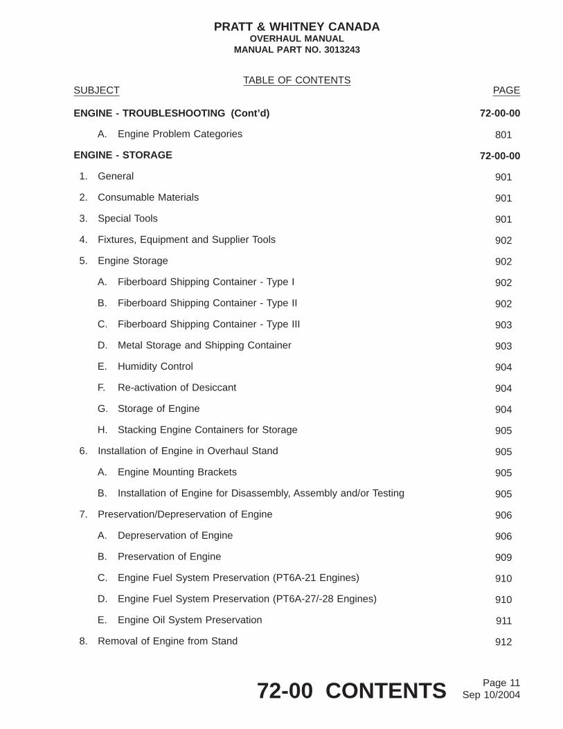
A. Engine Problem Categories 801
ENGINE - STORAGE 72-00-00
1. General 901
2. Consumable Materials 901
3. Special Tools 901
4. Fixtures, Equipment and Supplier Tools 902
5. Engine Storage 902
A. Fiberboard Shipping Container - Type I 902
B. Fiberboard Shipping Container - Type II 902
C. Fiberboard Shipping Container - Type III 903
D. Metal Storage and Shipping Container 903
E. Humidity Control 904
F. Re-activation of Desiccant 904
G. Storage of Engine 904
H. Stacking Engine Containers for Storage 905
6. Installation of Engine in Overhaul Stand 905
A. Engine Mounting Brackets 905
B. Installation of Engine for Disassembly, Assembly and/or Testing 905
7. Preservation/Depreservation of Engine 906
A. Depreservation of Engine 906
B. Preservation of Engine 909
C. Engine Fuel System Preservation (PT6A-21 Engines) 910
D. Engine Fuel System Preservation (PT6A-27/-28 Engines) 910
E. Engine Oil System Preservation 911
8. Removal of Engine from Stand 912
TABLE OF CONTENTSSUBJECT PAGE
PRATT & WHITNEY CANADAOVERHAUL MANUAL
MANUAL PART NO. 3013243
Page 1172-00 CONTENTS Sep 10/2004

ENGINE - STORAGE (Cont’d) 72-00-00
A. Procedure 912
9. Removal of Engine From Container 912
A. Procedure 912
B. Removal of Engine from Type I Fiberboard Container 913
C. Removal of Engine from Type II Fiberboard Container 913
D. Removal of Engine from Type III Fiberboard (reinforced)Container 918
E. Removal of Engine from Metal Container 918
10. Installation of Engine in Fiberboard Container 921
A. Preparation 921
B. Installation of Engine in Type I Fiberboard Container 921
C. Installation of Engine in Type II Fiberboard Container 926
D. Installation of Engine in Type III Fiberboard (reinforced)Container : 928
11. Installation of Engine in Metal Container 929
A. Procedure 929
12. Renewal of Desiccant in Metal Container 931
A. Procedure 931
ENGINE - LIGHT OVERHAUL 72-00-00
1. General 1301
2. Light Overhaul 1301
A. Conditions which Require Light Overhaul 1301
3. Light Overhaul Reference Guide 1302
A. General 1302
B. Engine Problems and Defects 1302
4. Overtemperature 1303
TABLE OF CONTENTSSUBJECT PAGE
PRATT & WHITNEY CANADAOVERHAUL MANUAL
MANUAL PART NO. 3013243
Page 1272-00 CONTENTS Sep 10/2004

ENGINE - LIGHT OVERHAUL (Cont’d) 72-00-00
A. Procedure 1303
5. Dropped Engine 1303
A. Procedure 1303
B. General 1307
6. Unusual Oil Conditions - General 1307
A. General 1307
B. Metal Contaminants 1307
C. Particles 1307
D. Metal Chip 1307
E. Examples Of Possible Contamination 1307
F. Unusual Oil Conditions (Part A) 1307
G. Unusual Oil Conditions (Part B) 1308
H. Rectify Part A 1308
I. Rectify Part B 1309
7. Contamination by Fire Extinguishing Agents 1309
A. General 1309
B. Engines Contaminated by Fire Extinguishing Agents 1309
C. Removal of Residual Deposits and Corrosion Repair 1310
8. Power Section 1310
9. Engine Components 1310
A. General 1310
10. Accessories 1311
11. External Components 1311
A. Problems 1311
B. General 1311
TABLE OF CONTENTSSUBJECT PAGE
PRATT & WHITNEY CANADAOVERHAUL MANUAL
MANUAL PART NO. 3013243
Page 1372-00 CONTENTS Sep 10/2004

ENGINE - LIGHT OVERHAUL (Cont’d) 72-00-00
12. Testing 1312
TABLE OF CONTENTSSUBJECT PAGE
PRATT & WHITNEY CANADAOVERHAUL MANUAL
MANUAL PART NO. 3013243
Page 1472-00 CONTENTS Sep 10/2004
ENGINE - DESCRIPTION AND OPERATION
1. Description and Operation
Refer to applicable Engine Maintenance Manual for Description and Operation.
2. Engine Specifications and Leading Particulars
Refer to applicable Engine Maintenance Manual for Engine Specifications and LeadingParticulars.
3. Engine Stations, Flanges and Bearings
Refer to applicable Engine Maintenance Manual for Engine Stations, Flanges and Bearings.
PRATT & WHITNEY CANADAOVERHAUL MANUAL
MANUAL PART NO. 3013243
72-00-00 Page 1/2ENGINE - DESCRIPTION AND OPERATION Mar 05/2004


ENGINE - DISASSEMBLY-1: EXTERNAL COMPONENTS
1. General
A. Personnel engaged in the disassembly of the engine should make frequent reference tothe Introduction sections of this manual to familiarize themselves with general overhaulprocedures (Ref. INTRODUCTION, Outline of Overhaul Procedures).
B. On receipt of an engine for overhaul, remove air inlet screen and examine for foreignobject damage (F.O.D.) in compressor rotor assembly. Inspect for external damage,burning, corrosion or signs of leakage. Record all observations made at this inspectionto provide reference during disassembly of engine, taking special notice of anydiscrepancy which might not be apparent after cleaning. Tag all affected parts to identifynature of fault. After removal from engine, submit affected parts to detailed inspectionbefore cleaning.
C. During inspection of engine, check that all externally mounted parts and accessories arecorrectly assembled; loose and/or unattached components usually indicate these partshave been replaced due to a previous unserviceability. Record all discrepancies and checkagainst data sheets received with engine for information relating to unserviceabilitiesencountered during service.
D. Overhaul facilities may find it more expedient to remove certain parts before others, sodisassembly sequences given in the text need not be strictly adhered to. Instructions forremoval of some standard parts, such as loop clamps and similar attaching hardware,may be repeated in areas hardware such parts support more than one component.
E. Cover all openings as soon as possible after removal of external parts and accessoryunits. Place each component in a separate polyethylene bag, or dust-proof container,and store on suitable racks until required for overhaul. Ensure that parts are segregatedduring storage to prevent damage by impact.
F. When engine is separated at bolting flanges, install major assemblies in appropriatestands and, unless being worked on, cover with plastic sheeting and seal to preventingress of moisture and foreign material.
G. To prevent damage to seal grooves and lands, use plastic spatulas when removingpreformed packings. Damage in these areas can cause improper seating and resultin subsequent leakage.
H. Discard all preformed packings, packing retainers, back-up rings, tabwashers, cotterpinsand gaskets immediately after removal to prevent possible reuse of these items.
2. Consumable Materials
Not Applicable
PRATT & WHITNEY CANADAOVERHAUL MANUAL
MANUAL PART NO. 3013243
72-00-00 Page 101ENGINE - DISASSEMBLY-1: EXTERNAL COMPONENTS Nov 30/2001

3. Special Tools
The special tools listed below are used in the following procedures.
Tool No. Name
PWC30077 PullerDELETEDPWC30800 Stand, Engine
4. Fixtures, Equipment and Supplier Tools
Not Applicable
5. Preparation for Disassembly
A. General
Install engine in stand (PWC30800) (Ref. Storage Instructions).
B. Draining Engine Oil System (Ref. Fig. 101)
(1) Place suitable oil container and drip pan under engine.
(2) Remove oil drain plug Pre-SB1217, or cover and magnetic chip detectorPost-SB1217 (1) from bottom of propeller reduction gearbox.
(3) Pre-SB1482: Remove cotterpin (3) and straight pin (2) from bottom of compressorinlet case. Remove drain plug 94) using puller (PWC30077).
(4) Remove drain plug (5) from 6 o’clock position on rear face of accessory gearbox.
(5) Allow all residual oil to drain from engine, then reinstall drain plugs and chip detector.
6. Removal of Externals
A. Removal of Oil Transfer Tubes (Ref. Fig. 102)
(1) Remove two bolts and washers, and separate front pressure oil elbow (16) fromreduction gearbox front housing and transfer tube (15). Discard preformed packing(17).
(2) Remove two self-locking nuts, washers and Dee-head bolts securing externalcoupling (13) to flange C.
(3) Separate front tube (15) from external coupling (13). Remove preformed packings(14) from tube.
(4) Withdraw center tube (11) from rear tube (6). Remove and discard preformedpacking (12).
(5) Remove bolts and self-locking nuts that secure seal retaining plate assemblies (10)and (5), and seals (9) and (4) to center and rear fireseal mount rings, respectively.
PRATT & WHITNEY CANADAOVERHAUL MANUAL
MANUAL PART NO. 3013243
72-00-00 Page 102ENGINE - DISASSEMBLY-1: EXTERNAL COMPONENTS Jul 02/2004

(6) Remove two bolts and washers that secure elbow (1) to compressor inlet case.
(7) Remove two bolts securing centre adapter flange of tube (6) to gas generator caseboss. Separate elbow from tube (6) and discard preformed packing (2).
(8) Separate adapter flange, and spacers (8), Pre-SB1169 from gas generator caseand withdraw transfer tube (6) from center and rear fireseals.
(9) Remove preformed packings (3 and 7), seal retaining plate assemblies (5 and 10),insulation plates (18 and 19) and seals (4 and 9) from rear transfer tube (6).
(10) Overhaul removed parts (Ref. 79-20-01).
B. No. 2 Bearing Scavenge Oil Tube Assembly (Ref. Fig. 103)
(1) To improve scavenge of No. 2 bearing, an oil scavenge tube assembly of largerdiameter, together with new seals and seal retaining plates Post-SB1153 areused. Disassemble oil tube and associated parts.
(a) Remove bolts securing front flange (3) of No. 2 bearing scavenge tube (11) togas generator case.
(b) Remove four bolts and self-locking nuts and seal retaining plates (4), sealretaining plate assemblies (5 and 7) and seals (6) from tube.
(c) Remove bolts securing rear flange (10) and support bracket (8) to compressorinlet case.
(d) Withdraw scavenge tube from bosses on gas generator and compressor inletcases, and remove tube rearward through hole in rear fireseal.
(e) Remove bolts and self-locking nuts, and separate support bracket (8) from rearfireseal.
(f) Remove preformed packings (1 and 9) from flanges of scavenge tube. Removegasket (2) from front flange (3).
(g) Overhaul removed parts (Ref. 79-20-01).
C. External Scavenge Oil Tubes (Ref. Fig. 104)
(1) Remove bolts and washers securing front elbow (5) to propeller reduction gearbox.
(2) Remove bolts, washers and self-locking nuts securing coupling (8) to flange C.
(3) Remove bolts and self-locking nuts securing seals (12), insulations (11) and retainingplates (18) to rear fireseal mount ring.
(4) Remove bolts and self-locking nuts securing seals (14) and retaining plates (13) tocenter fireseal mount ring.
(5) Withdraw front elbow (5) from short tube (2) and front tubes (7). Remove preformedpacking (3) and sleeve seal (4) from elbow.
PRATT & WHITNEY CANADAOVERHAUL MANUAL
MANUAL PART NO. 3013243
72-00-00 Page 103ENGINE - DISASSEMBLY-1: EXTERNAL COMPONENTS Nov 30/2001

VIEW A
VIEW B
VIEW C
CB
A
1
PRE−SB1217
POST−SB1217
5
2
43
PRE−SB1482
C8577A
Location of Oil Drain Plugs and Chip DetectorFigure 101
PRATT & WHITNEY CANADAOVERHAUL MANUAL
MANUAL PART NO. 3013243
72-00-00 Page 104ENGINE - DISASSEMBLY-1: EXTERNAL COMPONENTS Nov 30/2001

(6) Withdraw short transfer tube (2) from reduction gearbox, and remove two preformedpackings (1) from tube.
(7) Withdraw front tubes (7) from coupling (8). Remove preformed packings (6) fromeach tube.
(8) Remove coupling (8) from two rear transfer tubes (10).
(9) Remove rear tubes (10) from external scavenge pump ports, and carefully withdrawtubes from center and rear fireseal mount rings. Remove seals, insulations andretaining plates during withdrawal of tubes from mount rings.
(10) Remove preformed packings (9) from rear tubes.
(11) Disconnect coupling nut of scavenge oil hose (15) at adapter assembly onaccessory gearbox. Remove bolts and separate hose flange from accessory gearbox.Bracket (17) supporting fuel control (PT6A-27/28 engines); will be released.Remove preformed packing (16).
(12) Overhaul removed parts (Ref. 79-20-01).
D. Removal of Electrical Connector from Heated Pneumatic Lines (Ref. Figs. 106 through112)
(1) Remove self-locking nuts, washers, and screws (1, Fig. 105) securing electricalconnector (2) to bracket (1), and withdraw connector from bracket.
(2) Remove clamp screws (10) and separate half-clamps from bell end fitting (9).
(3) Unscrew bell end fitting (9) from flange-mounted connector shell (6) and slide fittingand cable sleeve (13) down electrical wires. Do not allow wires to twist whileunscrewing bell end fitting and ensure that braiding is not pulled back on wires.
(4) Slide nylon sleeve (8) and rubber insulator (7) back over wires to expose solderedconnections between wires and pins (14).
(5) Using suitable soldering iron, unsolder wires from pins (14).
(6) Carefully pull wires through rubber insulator (7) and nylon sleeve (8).
(7) Remove bell end fitting (9) and cable sleeve (13) from electrical cables (4) and (5).
(8) Reassemble components of connector (2) to avoid loss of parts.
Key to Figure 101
1. Chip Detector and Cover or Drain Plug (Ref. SB1217)2. Strain Pin Pre-SB14823. Cotterpin Pre-SB14824. Compressor Inlet Case Drain Plug Pre-SB14825. Accessory Gearbox Drain Plug
PRATT & WHITNEY CANADAOVERHAUL MANUAL
MANUAL PART NO. 3013243
72-00-00 Page 105ENGINE - DISASSEMBLY-1: EXTERNAL COMPONENTS Nov 30/2001

CFLANGE
13 14
15
10
14 16
17
REDUCTIONGEARBOX
12
11
19
1019
9
CENTER FIRESEALMOUNT RING
REAR FIRESEALMOUNT RING
5 18
518
4
1
23INLET CASE
3
7
8
6
GAS GENERATORCASE
C6980A
Pressure Oil TubesFigure 102
PRATT & WHITNEY CANADAOVERHAUL MANUAL
MANUAL PART NO. 3013243
72-00-00 Page 106ENGINE - DISASSEMBLY-1: EXTERNAL COMPONENTS Nov 30/2001
(9) Overhaul removed parts (Ref. 73-10-07).
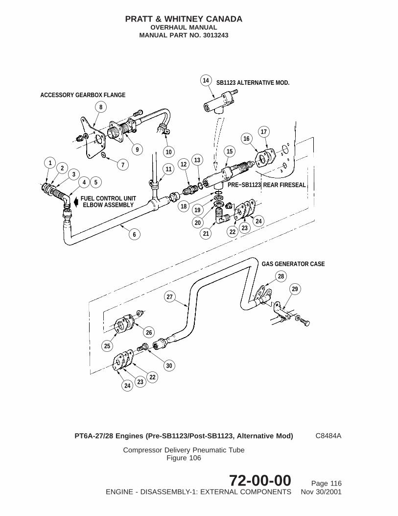
E. Compressor Delivery Air Line Installations (Ref. Figs. 106 through 112)
(1) Remove pneumatic tubes and temperature compensator (Pre-SB1123, AlternativeMod.) from PT6A-27/28 engine (Ref. Fig. 106):
(a) Remove self-locking nuts securing loop clamp (10), clamp and rubber grommet(11) and electrical receptacle bracket (8) to studs on flange G. Withdrawbracket and spacer (7) from studs. Tie spacer to bracket to prevent loss of part.
(b) Disconnect coupling nuts securing pneumatic insulated tube (27) and pneumaticheated tube (6) to temperature compensator (15) or compensator body (14).
(c) Remove two nuts securing temperature compensator (15) or compensator body(14) and two nuts and bolts (30) securing seal retaining plates (22), insulation(23) and seals (24) to rear fireseal.
(d) Remove temperature compensator (15) or compensator body (14) completewith insulation (16), (23), (25), seals (17) (24), seal retaining plates (22),retaining plate and insulation (26).
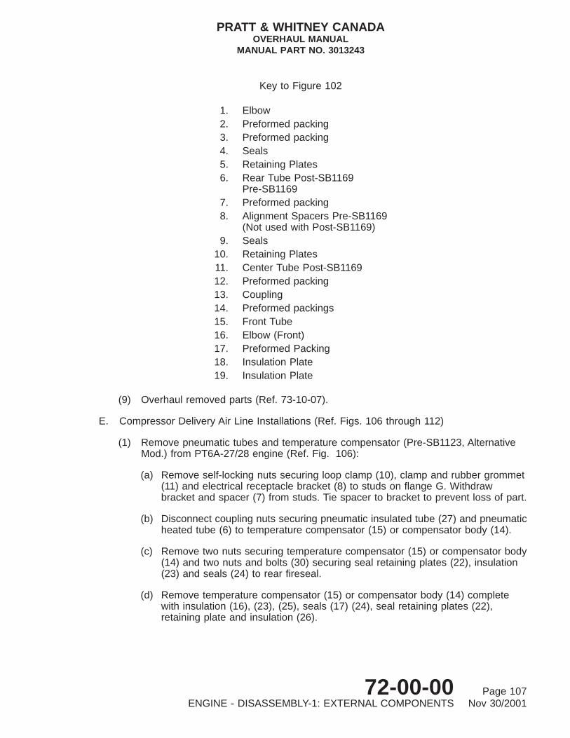
Key to Figure 102
1. Elbow2. Preformed packing3. Preformed packing4. Seals5. Retaining Plates6. Rear Tube Post-SB1169
Pre-SB11697. Preformed packing8. Alignment Spacers Pre-SB1169
(Not used with Post-SB1169)9. Seals
10. Retaining Plates11. Center Tube Post-SB116912. Preformed packing13. Coupling14. Preformed packings15. Front Tube16. Elbow (Front)17. Preformed Packing18. Insulation Plate19. Insulation Plate
PRATT & WHITNEY CANADAOVERHAUL MANUAL
MANUAL PART NO. 3013243
72-00-00 Page 107ENGINE - DISASSEMBLY-1: EXTERNAL COMPONENTS Nov 30/2001

1
2
3
45
6
REAR FIRESEALMOUNT RING
67
89 10
11
4
C7463
No. 2 Bearing Scavenge Oil TubeFigure 103
PRATT & WHITNEY CANADAOVERHAUL MANUAL
MANUAL PART NO. 3013243
72-00-00 Page 108ENGINE - DISASSEMBLY-1: EXTERNAL COMPONENTS Nov 30/2001

(e) Disconnect coupling nut securing pneumatic heated tube (6) to meteredelbow (4) or (5) on fuel control unit. Remove pneumatic heated tube (6) andelectrical cable.
(f) Disconnect coupling nut securing pneumatic heated tube (6) to metered elbow(4) or (5) on fuel control unit. Remove pneumatic heated tube (6) and electricalcable.
NOTE: Angle bracket (29) supporting ignition cable (spark ignition only) willbe released at this stage.
(g) Remove straight nipple (12) and preformed packing (13) from compensator orcompensator body.
(h) Overhaul removed parts (Ref. 73-10-07)
(2) Remove pneumatic tubes from PT6A-27/28 (Post-SB1123, Stnd. Mod.), and allPT6A-21 Engines: (Ref. Fig. 107)
(a) Remove self-locking nuts securing loop clamp (1), loop clamp and rubbergrommet (12) and electrical receptacle bracket to studs on flange G.Withdraw bracket and spacer from studs. Tie spacer to bracket to prevent lossof part.
(b) Remove self-locking nut and bolt securing loop clamp (9) to angle bracket (10).
(c) Remove two self-locking nuts and bolts, at rear fireseal mount ring securingseal retaining plates (3) and (6), insulations (4), seals (5) and angle bracket(10). Remove seal retaining plate (6) (Post-SB1162).
Key to Figure 103
1. Preformed Packing2. Gasket3. Front Flange4. Seal Retaining Plate
Pre-SB1173/Post-SB11735. Seal Retaining Plate Assembly
Pre-SB1153/Post-SB11536. Seal Pre-SB1153/Post-SB11537. Seal Retaining Plate Assembly
Pre-SB1153/Post-SB11538. Rear Fireseal Mount Ring Support Bracket9. Preformed Packing
10. Rear Flange11. No. 2 Bearing Scavenge Tube
Pre-SB1153/Post-SB1153PT6A-27/28 Engines (Ref. SB1153)PT6A-21 Engines (Basic)
PRATT & WHITNEY CANADAOVERHAUL MANUAL
MANUAL PART NO. 3013243
72-00-00 Page 109ENGINE - DISASSEMBLY-1: EXTERNAL COMPONENTS Nov 30/2001

7
68
B
5
43
2
6
1
A
914
11
9
10
13
CENTER FIRESEALMOUNT RING
REAR FIRESEALMOUNT RING
15
1617
C
CBA
12
C7464
External Scavenge Oil TubesFigure 104
PRATT & WHITNEY CANADAOVERHAUL MANUAL
MANUAL PART NO. 3013243
72-00-00 Page 110ENGINE - DISASSEMBLY-1: EXTERNAL COMPONENTS Nov 30/2001

(d) Disconnect coupling nut of pneumatic heated tube (11) at fuel control unit elbow.Remove two bolts and separate tube flange and gasket (8) from gas generatorcase.
NOTE: Angle bracket supporting ignition cable (spark ignition only) will bereleased at this stage.
(e) Remove seal retaining plate (3), insulations (4) and seals (5) from tube (11).
(f) Withdraw tube assembly (11) and cable (2) from slot in rear fireseal mount ring.
(g) Overhaul removed parts (Ref. 73-10-07).
(3) Remove pneumatic tubes and air filter from PT6A-27/28 (Post-SB1205) engines, asfollows: (Ref. Fig. 108).
(a) Remove self-locking nuts securing loop clamp (1), loop clamp and rubbergrommet (14) and electrical receptacle bracket to studs on flange G.Withdraw bracket and spacer from studs. Tie spacer to bracket to prevent lossof part.
(b) Disconnect coupling nuts of pneumatic heated tube (3) at fuel control unitelbow and air filter (6), and remove tube with cable (2).
(c) Remove two self-locking nuts and bolts at rear fireseal mount ring, and releaseseal retaining plates (7) and (10), insulations (8) and seals (9). Remove sealretaining plate (10) (Post-SB1162).
Key to Figure 104
1. Preformed Packing2. Transfer Tube3. Preformed Packing4. Sleeve Seal5. Front Scavenge Oil Transfer Elbow6. Preformed Packing7. Front Transfer Tube8. External Scavenge Oil Transfer Coupling9. Preformed Packing
10. Rear Transfer Tubes11. Insulation12. Seals13. Retaining Plates14. Seals15. Scavenge Oil Hose16. Preformed Packing17. Bracket (Support Starting Flow Control)
(PT6A-27/28 Engines)
PRATT & WHITNEY CANADAOVERHAUL MANUAL
MANUAL PART NO. 3013243
72-00-00 Page 111ENGINE - DISASSEMBLY-1: EXTERNAL COMPONENTS Nov 30/2001

VIEW ON ARROW B
6 7 8 9 16
11
4
514 10 13
12
EXPLODED
B
6D
C
A
B
ELECTRICAL SCHEMATIC
11
12
AGFLANGE
A
FOR ENGINE/S.B. APPLICABILITY REFER TO TABLE 101 OR 501
GFLANGE
REAR FIRESEAL
1
23
4
5
C10413
Electrical Connector for Heated Pneumatic LinesFigure 105 (Sheet 1 of 2)
PRATT & WHITNEY CANADAOVERHAUL MANUAL
MANUAL PART NO. 3013243
72-00-00 Page 112ENGINE - DISASSEMBLY-1: EXTERNAL COMPONENTS Nov 30/2001

Key to Figure 105
1. Screw2. Bracket3. Electrical Connector4. Governor Pneumatic Heated Tube Electrical Cable5. Compressor Delivery Pneumatic Heated Tube Electrical
Cable (Sheet 1)Compressor Delivery Pneumatic Heated Tube ElectricalCable andCompressor Delivery Pneumatic Heated Center TubeElectrical Cable (Sheet 2)
6. Connector Shell7. Rubber Insulator8. Nylon Sleeve9. Bell-end Fitting
10. Clamp Screw11. Element in Governor Pneumatic Heated Tube12. Element in Compressor Delivery Pneumatic Heated Hose13. Cable Sleeve14. Pins15. Element in Compressor Delivery Pneumatic Heated Center
Tube16. Loop Clamp and Rubber Grommet
PRATT & WHITNEY CANADAOVERHAUL MANUAL
MANUAL PART NO. 3013243
72-00-00 Page 113ENGINE - DISASSEMBLY-1: EXTERNAL COMPONENTS Nov 30/2001

REAR FIRESEAL
DETAIL AGFLANGE
EXPLODED VIEW ON ARROW B
B
1
23
5
4
GFLANGE
A
6D
C
A
B
15
12
11
ELECTRICAL SCHEMATIC
6 7 8 9
14
10
12
5
4
16
13
11
15
C8495C
Electrical Connector for Heated Pneumatic LinesFigure 105 (Sheet 2)
PRATT & WHITNEY CANADAOVERHAUL MANUAL
MANUAL PART NO. 3013243
72-00-00 Page 114ENGINE - DISASSEMBLY-1: EXTERNAL COMPONENTS Nov 30/2001

(d) Disconnect coupling nut of pneumatic insulated tube (13) at forward end of airfilter (6). Remove two bolts and separate tube flange and gasket (12) from gasgenerator case.
NOTE: Angle bracket (11) supporting ignition cable (spark ignition only) willbe released at this stage.
(e) Withdraw tube assembly (13) from slot in rear fireseal mount ring and removeseal retaining plates (7) insulations (8) and seals (9).
(f) Remove two self-locking nuts securing support bracket (5) to studs on flange Gand remove bracket (5) and air filter (6). Remove two self-locking nuts securingsupport bracket (5) to studs on flange G and remove bracket (5) and air filter(6).
(g) Remove locknut (4) securing air filter (6) to support bracket (5) and remove airfilter.
(h) Overhaul removed parts (Ref. 73-10-07).
TABLE 101, Engine/Service Bulletin Applicability
Engine Model Service Bulletin No. Fig. No. Sheet No.
PT6A-21 Pre-SB1330 105 1
Post-SB1330 105 2
PT6A-27 Pre-SB1123 105 1
Post-SB1123 105 1
Post-SB1205 105 1
Post-SB1330 105 2
Post-SB1343 105 1
Post-SB1378 105 2
Post-SB1448 105 2
PT6A-28 Pre-SB1123 105 1
Post-SB1123 105 1
Post-SB1205 105 1
Post-SB1290 105 2
Post-SB1314 105 2
Post-SB1330 105 2
Post-SB1343 105 1
Post-SB1448 105 2
(4) Remove pneumatic tubes and bowl-type filter from PT6A-28 (Post-SB1290)engines: (Ref. Fig. 109)
PRATT & WHITNEY CANADAOVERHAUL MANUAL
MANUAL PART NO. 3013243
72-00-00 Page 115ENGINE - DISASSEMBLY-1: EXTERNAL COMPONENTS Nov 30/2001
28
29
GAS GENERATOR CASE
27
26
25
24 2322
30
14 SB1123 ALTERNATIVE MOD.
8
7
9 10
ACCESSORY GEARBOX FLANGE
12
34
6
FUEL CONTROL UNITELBOW ASSEMBLY
5
1112
1315
19
20
21
18
1617
2223
24
PRE−SB1123 REAR FIRESEAL
C8484A
Compressor Delivery Pneumatic TubeFigure 106
PT6A-27/28 Engines (Pre-SB1123/Post-SB1123, Alternative Mod)
PRATT & WHITNEY CANADAOVERHAUL MANUAL
MANUAL PART NO. 3013243
72-00-00 Page 116ENGINE - DISASSEMBLY-1: EXTERNAL COMPONENTS Nov 30/2001

(a) Remove self-locking nuts (5) securing loop clamp (7) and electricalreceptacle bracket (6) to studs on flange G; withdraw spacer and bracket fromstuds and tie spacer to bracket to avoid loss of part.
Key to Figure 106
1. Preformed Packing2. Back-up Ring3. Locknut4. Elbow (Pre-SB1123)5. Metered Elbow (Post-SB1123, Alternative Mod.)6. Compressor Delivery Pneumatic Heated Tube7. Spacer8. Electrical Receptacle Bracket9. Electrical Receptacle
10. Loop Clamp11. Loop Clamp and Rubber Grommet12. Straight Nipple13. Preformed Packing14. Compensator Body
(Post-SB1123, Alternative Mod)15. Temperature Compensator
(Pre-SB1123)16. Insulation17. Seal18. Preformed packing19. Back-up Ring20. Locknut21. Elbow22. Retaining Plate23. Insulation24. Seal25. Insulation26. Retaining Plate and Insulation27. Compressor Delivery Pneumatic Insulated Tube28. Gasket29. Angle Bracket (Engines with spark igniters only)30. Bolt 0.190-32 UNJF x 0.625 inch. - Alternative: Bolt
0.190-32 IUNJF x 0.750 inch (Ref. IPC).
PRATT & WHITNEY CANADAOVERHAUL MANUAL
MANUAL PART NO. 3013243
72-00-00 Page 117ENGINE - DISASSEMBLY-1: EXTERNAL COMPONENTS Nov 30/2001

GFLANGE
GOVERNOR AIR PRESSUREHEATED TUBE ELECTRICAL CABLE
ELECTRICAL RECEPTACLE BRACKET
1 12
2
FUEL CONTROLUNIT ELBOW
ASSY.
34
56
54
3
119
10
REAR FIRESEALMOUNT RING
8
7
GAS GENERATORCASE
C7466A
Compressor Delivery Air Line InstallationFigure 107
PT6A-27/28 Engines (Post-SB1123, Stnd Mod) and all PT6A-21 Engines
PRATT & WHITNEY CANADAOVERHAUL MANUAL
MANUAL PART NO. 3013243
72-00-00 Page 118ENGINE - DISASSEMBLY-1: EXTERNAL COMPONENTS Nov 30/2001
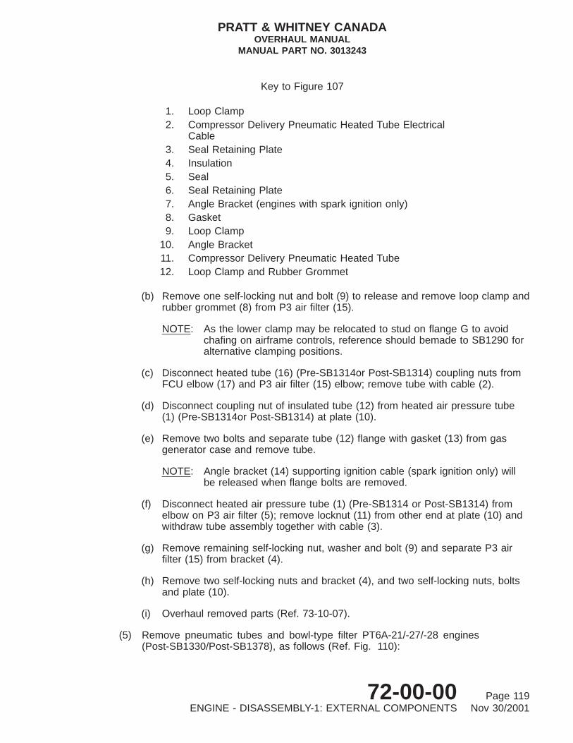
(b) Remove one self-locking nut and bolt (9) to release and remove loop clamp andrubber grommet (8) from P3 air filter (15).
NOTE: As the lower clamp may be relocated to stud on flange G to avoidchafing on airframe controls, reference should bemade to SB1290 foralternative clamping positions.
(c) Disconnect heated tube (16) (Pre-SB1314or Post-SB1314) coupling nuts fromFCU elbow (17) and P3 air filter (15) elbow; remove tube with cable (2).
(d) Disconnect coupling nut of insulated tube (12) from heated air pressure tube(1) (Pre-SB1314or Post-SB1314) at plate (10).
(e) Remove two bolts and separate tube (12) flange with gasket (13) from gasgenerator case and remove tube.
NOTE: Angle bracket (14) supporting ignition cable (spark ignition only) willbe released when flange bolts are removed.
(f) Disconnect heated air pressure tube (1) (Pre-SB1314 or Post-SB1314) fromelbow on P3 air filter (5); remove locknut (11) from other end at plate (10) andwithdraw tube assembly together with cable (3).
(g) Remove remaining self-locking nut, washer and bolt (9) and separate P3 airfilter (15) from bracket (4).
(h) Remove two self-locking nuts and bracket (4), and two self-locking nuts, boltsand plate (10).
(i) Overhaul removed parts (Ref. 73-10-07).
(5) Remove pneumatic tubes and bowl-type filter PT6A-21/-27/-28 engines(Post-SB1330/Post-SB1378), as follows (Ref. Fig. 110):
Key to Figure 107
1. Loop Clamp2. Compressor Delivery Pneumatic Heated Tube Electrical
Cable3. Seal Retaining Plate4. Insulation5. Seal6. Seal Retaining Plate7. Angle Bracket (engines with spark ignition only)8. Gasket9. Loop Clamp
10. Angle Bracket11. Compressor Delivery Pneumatic Heated Tube12. Loop Clamp and Rubber Grommet
PRATT & WHITNEY CANADAOVERHAUL MANUAL
MANUAL PART NO. 3013243
72-00-00 Page 119ENGINE - DISASSEMBLY-1: EXTERNAL COMPONENTS Nov 30/2001

1311
12 GAS GENERATORCASE
GFLANGE
3
4
5
6
78910
98
7
2
1
ELECTRICAL RECEPTACLEBRACKET
GOVERNOR AIR PRESSURE HEATEDTUBE ELECTRICAL CABLE
FUEL CONTROLUNIT ELBOW ASSEMBLY
REAR FIRESEALMOUNT RING
14
C8508
Compressor Delivery Air Line InstallationFigure 108
PT6A-27/28 Engines (Post-SB1205)
PRATT & WHITNEY CANADAOVERHAUL MANUAL
MANUAL PART NO. 3013243
72-00-00 Page 120ENGINE - DISASSEMBLY-1: EXTERNAL COMPONENTS Nov 30/2001

(a) Remove self-locking nut and bolt (19) to release loop clamp and rubber grommetfrom angle bracket (17) (Post-SB1330). Remove loop clamp and rubbergrommet.
(b) Disconnect tube (15) coupling nuts from FCU elbow (16) and P3 air filter (14)elbow; remove tube with cable (3).
(c) Disconnect tube (11) coupling nut from tube (1) at plate (9).
(d) Remove two bolts and separate tube (11) flange with gasket (12) from gasgenerator case and remove tube.
NOTE: Angle bracket (13) supporting ignition cable (spark ignition only) willbe released when flange bolts are removed.
(e) Disconnect heated center tube (1) from elbow on P3 air filter (14); removelocknut (10) from other end at plate (9) and withdraw tube assembly togetherwith cable (2).
(f) Remove self-locking nuts, bolts (8), angle bracket (17) and washer(Post-SB1583engines, remove self-locking nuts, washers, bolts (23), anglebracket and washers). Separate P3 air filter (14) from bracket (4).
(g) Remove self-locking nuts (5) securing electrical receptacle bracket (6) and P3air filter bracket (4) to studs on flange G; withdraw spacers (18) and (20) andbrackets from studs. To avoid loss tie spacer to bracket (6).
(h) Overhaul removed parts (Ref. 73-10-07).
Key to Figure 108
1. Loop Clamp2. Compressor Delivery Pneumatic Heated
Tube Electrical Cable3. Compressor Delivery Pneumatic
Heated Tube4. Locknut5. Support Bracket6. Air Filter7. Seal Retaining Plate8. Insulation9. Seal
10. Seal Retaining Plate11. Angle Bracket (engines with spark ignition only)12. Gasket13. Compressor Delivery Insulated Tube14. Loop Clamp and Rubber Grommet
PRATT & WHITNEY CANADAOVERHAUL MANUAL
MANUAL PART NO. 3013243
72-00-00 Page 121ENGINE - DISASSEMBLY-1: EXTERNAL COMPONENTS Nov 30/2001

12
13
14
IGNITION CABLE
16
17
FUEL CONTROL UNITELBOW ASSEMBLY
1
2 3
5
4
6
7
ELECTRICAL RECEPTACLEBRACKET
GOVERNOR AIR PRESSUREHEATED TUBE ELECTRICAL
CABLE
8 910
11
15
C8485
Compressor Delivery Air Line InstallationFigure 109
PT6A-28 Engines (Post-SB1290)
PRATT & WHITNEY CANADAOVERHAUL MANUAL
MANUAL PART NO. 3013243
72-00-00 Page 122ENGINE - DISASSEMBLY-1: EXTERNAL COMPONENTS Nov 30/2001

(6) Remove pneumatic tubes and bowl type filter PT6A-27/28 engines(Post-SB1343): (Ref. Fig. 111).
(a) Remove self-locking nuts (6) securing loop clamp (3) and electrical receptaclebracket (7) to studs on flange G; withdraw spacer and bracket from studs andtie spacer to bracket to avoid loss of part.
(b) Remove one self-locking nut, bolt (17) and washer (Post-SB1583 engines,remove one self-locking nut, Tee bolt (21) and two washers) to release andremove loop clamp and rubber grommet (16) from P3 air filter (18).
(c) Disconnect heated hose (19) from FCU elbow (20) and P3 air filter (18);remove tube with cable (2).
(d) Disconnect insulated tube (10) coupling nut from tube (1) at plate (15).
(e) Remove two bolts (12) and separate tube (10) flange with gasket (11) from gasgenerator case and remove tube.
NOTE: Angle bracket (13) supporting ignition cable (spark ignition only) willbe released when flange bolts are removed.
Key to Figure 109
1. Compressor Delivery Pneumatic Heated Air Pressure TubeAssembly(Post-SB1290/Pre-SB1314),(Post-SB1314)
2. Electrical Cable3. Electrical Cable4. Bracket5. Nut6. Electrical Receptacle Bracket7. Loop Clamp8. Loop Clamp and Rubber Grommet9. Bolt
10. Plate11. Locknut12. Compressor Delivery Pneumatic Insulated Tube13. Gasket14. Angle Bracket (engine with spark ignition only)15. P3 Air Filter16. Compressor Delivery Heated Air Pressure Tube Assembly
(Post-SB1290/Pre-SB1314),(Post-SB1314)
17. Elbow
PRATT & WHITNEY CANADAOVERHAUL MANUAL
MANUAL PART NO. 3013243
72-00-00 Page 123ENGINE - DISASSEMBLY-1: EXTERNAL COMPONENTS Nov 30/2001

(f) Disconnect insulated center tube (1) from elbow on P3 air filter (18); removelocknut (14) from other end at plate (15) and withdraw tube.
(g) Remove remaining self-locking nut, washer and bolt (17) (Post-SB1583engines, remove remaining self-locking nut, Tee bolt (21) and two washers).Separate P3 air filter (18) from bracket (4).
(h) Remove self-locking nuts (8), bolts (9) and plate (15) and self-locking nuts,bracket (4) and spacers (5), tie spacers to bracket to avoid loss.
(i) Overhaul removed parts (Ref. 73-10-07).
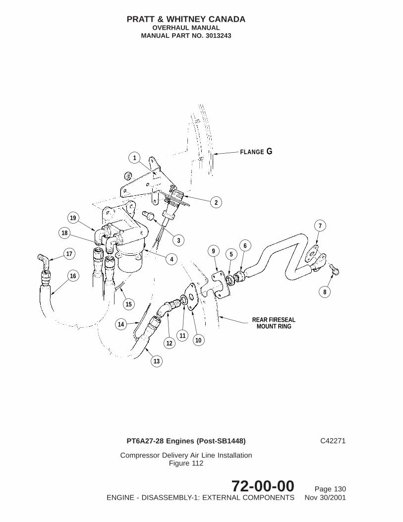
(7) Remove pneumatic hoses, tube and bowl type filter from PT6A-27/-28 engines(Post-SB1448), as follows (Ref. Fig. 112):
(a) With electrical cables (14 and 15) disconnected (Ref. Para. D. preceding),disconnect rear heated hose assembly (16) from FCU elbow (17) and P3filter assembly (4) outer elbow (18).
(b) Disconnect center heated hose assembly from elbow (12) on rear fireseal andP3 filter assembly (4) inner elbow (19).
(c) Loosen coupling nut on insulated tube (6) at rear fireseal mount ring andremove bolts (8) on flange end mounted to gas generator case boss. Disconnectcoupling nut, remove tube and gasket (7). Discard gasket.
(d) Remove self-locking nuts from bolts (3) and P3 filter assembly from bracketassembly (1) mounted on flange G.
(e) Remove locknut (5) elbow (12) and washer (11).
(f) Remove self-locking nuts and bolts, tube retaining plate (10) and seal retainingplate (9).
(g) Overhaul removed parts (Ref. 73-10-07).
F. Propeller Governor Pneumatic Tubes (Ref. Fig. 113)
(1) Remove self-locking nut and loop clamp (2) from top mounting stud of fuel pump.
(2) Remove self-locking nuts and bolts at rear fireseal mount ring, and release sealretaining plates (5 and 8), insulations (6), and seals (7); remove slotted retainingplate (8) (Post-SB1162).
(3) Disconnect heated tube (4) from elbow (1) and coupling (9); withdraw tubeassembly and cable (3) from slot in rear fireseal mount ring.
(4) Remove self-locking nut and bolt securing loop clamp (13) to angle bracket (12) atflange C.
(5) Disconnect coupling nuts of pneumatic front tube (11) at nipple (14) and bulkheadcoupling (9); remove tube assembly, seal retaining plates (5), insulations (6) andseals (7).
PRATT & WHITNEY CANADAOVERHAUL MANUAL
MANUAL PART NO. 3013243
72-00-00 Page 124ENGINE - DISASSEMBLY-1: EXTERNAL COMPONENTS Nov 30/2001

(6) Remove locknut (10) and separate coupling (9) from center fireseal mount ring.
(7) Overhaul removed parts (Ref. 73-10-08).
G. Fuel Tubes and Flexible Hoses (PT6A-21 Engines) (Ref. Fig. 114)
(1) Disconnect coupling nuts at each end of flexible fuel hose (2) from oil-to-fuel heaterand fuel pump. Remove tube and cap all openings.
(2) Disconnect coupling nuts at each end of flexible fuel hose (1) from fuel pump andfuel control unit (FCU). Remove tube and cap all openings.
(3) For Pre-SB1471 Engines: Disconnect coupling nuts at each end of fuel tube (3)from FCU and bulkhead coupling (6) at fuel pressure tube bracket (5). Removetube and cap all openings.
(4) For Post-SB1471 Engines:
(a) Disconnect coupling nuts at each end of fuel tube (3) from FCU and tubeassembly (24) or fuel flowmeter (25) (if fitted).
(b) Remove nut (26) and bolt (27) which secures loop clamp (28) to bracket (29).
(c) Remove tube (3) and cap all openings.
(d) Separate tube assembly (24) or fuel flowmeter (25) from tube assembly (30).
(5) Remove jam nut (4) which secures fuel pressure tube bracket (5) to rear firesealmount ring.
(6) Remove self-locking nuts (11) from bolts (10) at rear fireseal mount ring, andremove fuel line seals (9), retaining plates (7) and insulation (8) from tube.
(7) Remove self-locking nuts (19) from bolts (18) at center fireseal mount ring, andremove fuel line seals (17), retaining plates (15) and insulation (16) from tube.
(8) Disconnect coupling nuts at each end of fuel tube (20) from bulkhead coupling (6)at fuel pressure tube bracket (5) and elbow fitting on flow divider valve.
(9) Remove self-locking nut (13) and bolt (14) securing loop clamp (12) and washer(21) to support bracket (22) at rear of fuel drain valve.
(10) Remove nuts and bolts securing fuel line loop clamp (12) to similar loop clamp onignition cable and loop clamp (23) (glow plug ignition only).
(11) Overhaul removed parts (Ref. 73-10-08).
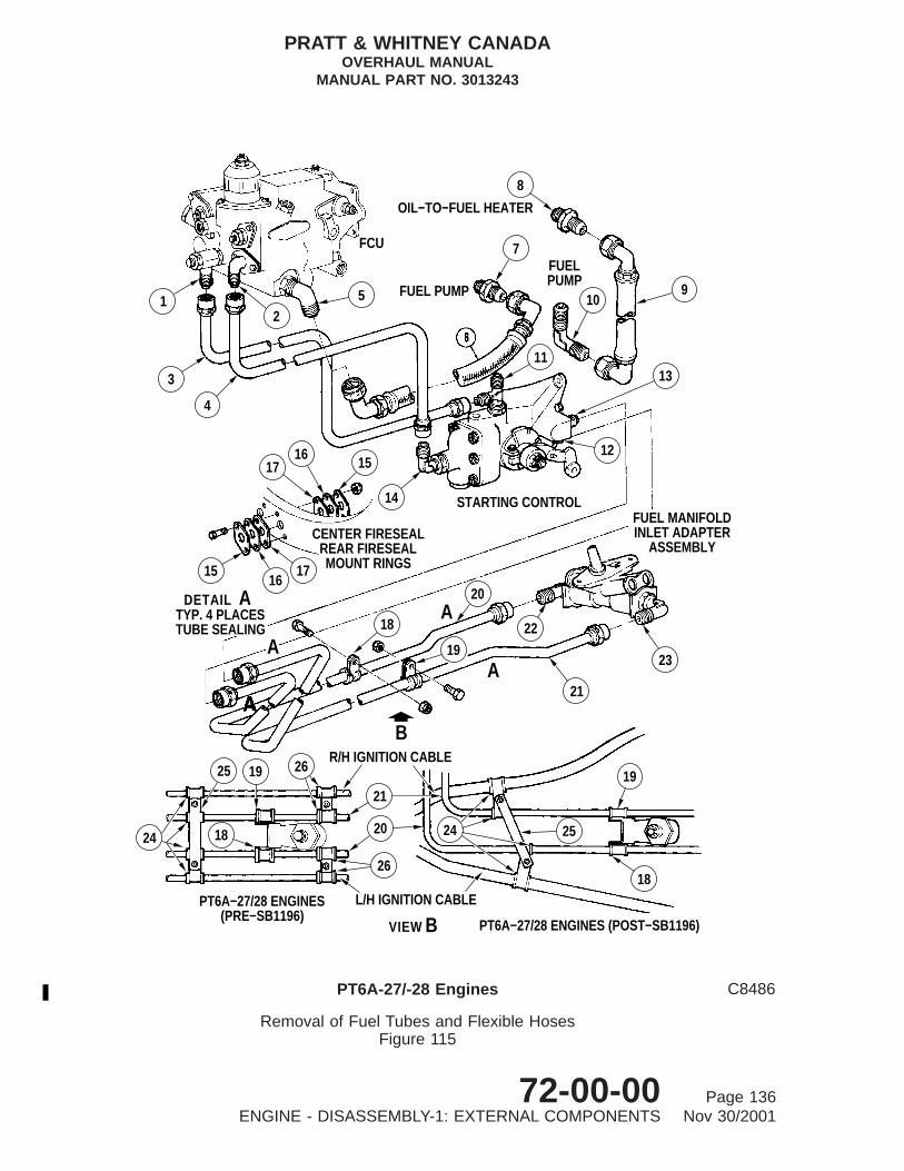
H. Fuel Tubes and Flexible Hoses (PT6A-27/-28 Engines) (Ref. Fig. 115)
(1) Disconnect coupling nuts of fuel hose (6) at elbow (5) and straight nipple (7);remove hose.
PRATT & WHITNEY CANADAOVERHAUL MANUAL
MANUAL PART NO. 3013243
72-00-00 Page 125ENGINE - DISASSEMBLY-1: EXTERNAL COMPONENTS Nov 30/2001

14
78
POST−SB1378
186
5
4
20
14
17
19
7 8
15
32
1
16TO FUEL
CONTROL 910
12
1311
23
22
144
2122
22
DETAIL APOST−SB1583
A
C79904
Compressor Delivery Air Line InstallationFigure 110
PT6A-21/27/28 Engines (Post-SB1330/SB1378)
PRATT & WHITNEY CANADAOVERHAUL MANUAL
MANUAL PART NO. 3013243
72-00-00 Page 126ENGINE - DISASSEMBLY-1: EXTERNAL COMPONENTS Nov 30/2001

(2) Disconnect coupling nuts of fuel hose (9) at straight nipple (8) and elbow (10); removehose.
NOTE: Item (9) is not fitted (i.e. airframe-supplied) on some PT6A-28 enginemodels.
(3) Disconnect coupling nuts of fuel bypass tube (3) at connector (1), and tee (11);remove tube.
(4) Disconnect fuel pressure tube (4) at adapter (2) and elbow (14), and remove tubeassembly.
(5) Remove self-locking nuts and bolts (four places) on both center and rear firesealmount rings, and release seal retaining plates (15), insulations (16) and seals (17).
(6) Remove two self-locking nuts and bolts to release backing plate (25) and loop clamps(24) on fuel tube (20) and (21) and ignition cables.
(7) On engines with glow plug ignition (Pre-SB1196), remove two self-locking nuts andbolts to release loop clamps (26) on fuel tubes (20 and 21) and ignition cables.
Key to Figure 110
1. Compressor Delivery Pneumatic Heated Center Tube2. Electrical Cable3. Electrical Cable4. Bracket5. Nut6. Electrical Receptacle Bracket7. Loop Clamp and Rubber Grommet8. Bolt9. Plate
10. Locknut11. Compressor Delivery Pneumatic Insulated Tube12. Gasket13. Angle Bracket (engine with spark ignition only).14. P3 Air Filter15. Compressor Delivery Pneumatic Heated Hose16. Elbow17. Angle Bracket (Post-SB1330)18. Spacer19. Bolt20. Spacer21. Nut22. Washer23. Bolt
PRATT & WHITNEY CANADAOVERHAUL MANUAL
MANUAL PART NO. 3013243
72-00-00 Page 127ENGINE - DISASSEMBLY-1: EXTERNAL COMPONENTS Nov 30/2001

20
19
FUEL CONTROL UNITELBOW ASSEMBLY
1013
11
12
IGNITION CABLE
GFLANGE
18
1617
1
2
6
3
7
54
8
9
1514
REAR FIRESEALMOUNT RING
ELECTRICAL RECEPTACLE BRACKET
GOVERNOR AIR PRESSURE HEATEDTUBE ELECTRICAL CABLE
APRE−SB1583
ADETAILPOST−SB1583
22 2318
16
21
22
4
GFLANGE
C10264A
Compressor Delivery Air Line InstallationFigure 111
PT6A27/-28 Engines (Post-SB1343)
PRATT & WHITNEY CANADAOVERHAUL MANUAL
MANUAL PART NO. 3013243
72-00-00 Page 128ENGINE - DISASSEMBLY-1: EXTERNAL COMPONENTS Nov 30/2001

(8) Remove two self-locking nuts, bolts and spacing washers (if fitted), to releaseloop clamps (18) and (19) from support bracket attached to rear drain valve ongas generator case.
(9) Disconnect fuel pressure tube (20) at straight nipple (12) and elbow (22).
(10) Withdraw tube (20) through center and rear fireseal mount rings and remove sealretaining plates, insulations and seals.
(11) Disconnect fuel pressure tube (21) at nipple (13) and elbow (23).
(12) Withdraw tube through center and rear fireseal mount rings, and remove sealretaining plates, insulations and seals.
(13) Overhaul removed parts (Ref. 73-10-03).
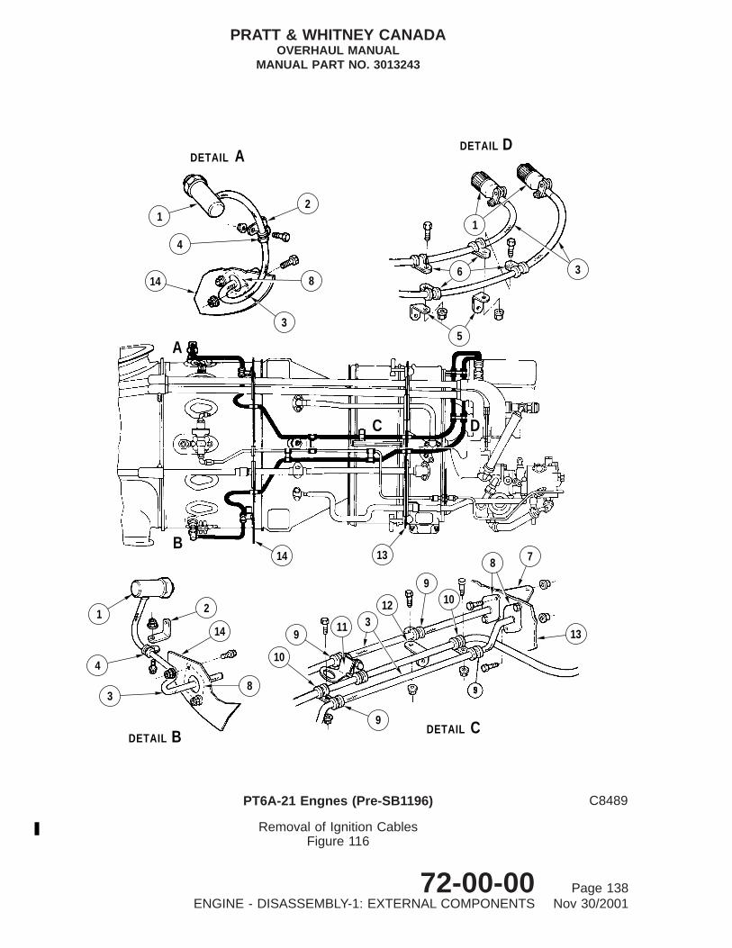
I. Ignition Cables (PT6A-21 Engines) (Ref. Fig. 116)
(1) Remove glow plug ignition cables (Pre-SB1196) (Ref. Fig. 116):
Key to Figure 111
1. Compressor Delivery Pneumatic Heated Center Tube2. Electrical Cable3. Loop Clamp4. Bracket Assembly5. Spacer6. Nut7. Electrical Receptacle Bracket8. Nut9. Bolt
10. Insulated Tube11. Gasket12. Bolt13. Angle Bracket14. Locknut15. Plate16. Loop Clamp and Rubber Grommet17. Bolt18. P3 Filter Assembly19. Heated Hose20. Elbow21. Tee Bolt22. Washer23. Nut
PRATT & WHITNEY CANADAOVERHAUL MANUAL
MANUAL PART NO. 3013243
72-00-00 Page 129ENGINE - DISASSEMBLY-1: EXTERNAL COMPONENTS Nov 30/2001
56
9
7
8
REAR FIRESEALMOUNT RING
GFLANGE
2
13
1211
10
14
19
18
17
16
15
4
3
1
C42271
Compressor Delivery Air Line InstallationFigure 112
PT6A27-28 Engines (Post-SB1448)
PRATT & WHITNEY CANADAOVERHAUL MANUAL
MANUAL PART NO. 3013243
72-00-00 Page 130ENGINE - DISASSEMBLY-1: EXTERNAL COMPONENTS Nov 30/2001

CAUTION: WHEN UNSCREWING COUPLING NUTS, DO NOT ALLOWBRAIDING, FERRULES OR IGNITER TO TURN AT SAME TIME.
(a) Disconnect left- and right-hand ignition cable connectors (1) from respectiveglow plug and ignition regulator.
(b) Remove self-locking nuts and bolts securing loop clamps (4) to angle brackets(2) on center fireseal mount ring (14) and integral brackets on gas generatorcase (Ref. Details A and B).
(c) Remove self-locking nuts and bolts securing cable flanges (8) to center firesealmount ring (14) (Details A and B).
(d) Remove self-locking nuts and bolts securing loop clamps (9) to brackets (12)(Ref. Detail C).
NOTE: Self-locking nuts and bolts securing loop clamps (9) to loop clamps(10) on fuel tubes, have been removed (Ref. Para. G.).
(e) Remove self-locking nuts and bolts securing cable flanges (8) to rear firesealmount ring (13) (Ref. Detail C).
NOTE: Mount ring support bracket (7) has been previously removed (Ref.Para. B., preceding).
Key to Figure 112
1. Bracket Assembly2. Electrical Connector3. Bolt4. P3 Air Filter Assembly5. Locknut6. Insulated Tube7. Gasket8. Bolt9. Plate, Seal Retaining
10. Plate, Tube Retaining11. Washer12. Elbow13. Center Heated Hose Assembly14. Electrical Cable, Center Hose15. Electrical Cable, Rear Hose16. Rear Heated Hose Assembly17. Elbow, FCU18. Outer Elbow19. Inner Elbow
PRATT & WHITNEY CANADAOVERHAUL MANUAL
MANUAL PART NO. 3013243
72-00-00 Page 131ENGINE - DISASSEMBLY-1: EXTERNAL COMPONENTS Nov 30/2001

4
2
3
1
FUEL CONTROL UNIT
4
9
10
CENTER FIRESEALMOUNT RING
11
14
11
12
13
TO PROPELLERGOVERNOR
CFLANGE
5 6 7 8
76 5REAR FIRESEAL
MOUNT RING
C7469A
Propeller Governor Pneumatic TubesFigure 113
PRATT & WHITNEY CANADAOVERHAUL MANUAL
MANUAL PART NO. 3013243
72-00-00 Page 132ENGINE - DISASSEMBLY-1: EXTERNAL COMPONENTS Nov 30/2001

(f) Remove self-locking nuts and bolts securing loop clamps (6) to anglebrackets (5) (Detail D).
(g) Withdraw ignition cables (3) through fireseal mount rings.
(h) Overhaul removed parts (Ref. 74-20-01).
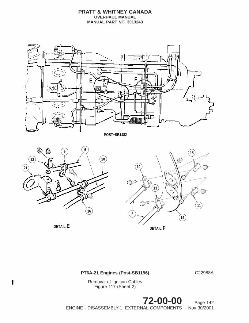
(2) Remove spark ignition cables (Post-SB1196, Pre-SB1482/Post-SB1482) : (Ref. Fig.117)
CAUTION: WHEN UNSCREWING CABLE COUPLING NUTS, DO NOT PERMITBRAIDING, FERRULES OR IGNITER TO TURN AT THE SAME TIME.
(a) Disconnect right and left hand ignition cable (6) connectors from respectivespark igniter and ignition exciter.
(b) Referring to Detail A: Remove self-locking nuts and bolts, separate loop clamps(1) and (5) from ignition cables (6) and angle brackets (2) and (3) on centerfireseal (4).
(c) Remove self-locking nuts and bolts to release cable (6) flanges from centerfireseal. Remove two brackets (3) from center fireseal.
(d) Detail B: Remove self-locking nut and bolt and separate clamps (7) and (8)from each other and from cables (6).
(e) Detail C: Remove self-locking nut, bolt and bracket (19) and separate loopclamp (18) from ignition cable.
NOTE: Bolt and washer retaining bracket (19) and flange of compressordelivery tube (17) were previously removed (Ref. Para. E.).
Key to Figure 113
1. Elbow (on FCU)2. Loop Clamp3. Electrical Cable4. Governor Pneumatic Tube - Heated5. Seal Retaining Plate6. Insulation7. Seal8. Seal Retaining Plate9. Coupling
10. Locknut11. Governor Pneumatic Tube - Front12. Angle Bracket13. Loop Clamp14. Straight Nipple
PRATT & WHITNEY CANADAOVERHAUL MANUAL
MANUAL PART NO. 3013243
72-00-00 Page 133ENGINE - DISASSEMBLY-1: EXTERNAL COMPONENTS Nov 30/2001

18
1615
1716
1519
CENTER FIRESEALMOUNT RING
20
FLOW DIVIDER ANDDUMP VALVE
1
45
6
PRE−SB1471
B
10 7
8
12
11
7
89
REAR FIRESEALMOUNT RING
20 1214
22
21
23
13
B
AFUELCONTROLUNIT
OIL−TO−FUEL HEATER
FUELPUMP
2
POST−SB1471
3
26
28
2927
24
30
3
25
VIEW A
VIEW
C7922C
Removal of Fuel Delivery Tubes and Flexible HosesFigure 114
PT6A-21 Engines
PRATT & WHITNEY CANADAOVERHAUL MANUAL
MANUAL PART NO. 3013243
72-00-00 Page 134ENGINE - DISASSEMBLY-1: EXTERNAL COMPONENTS Nov 30/2001

(f) Detail D, Pre-SB1482): Remove self-locking nuts and bolts and separateloop clamps (10) and (13) from brackets (11) and (15) at front of rear firesealmount ring (14). Remove clamps from cables (6).
(g) Remove self-locking nut and bolt. Separate loop clamp (9) from ignition cable(6) and bracket (22) on air inlet screen bolting flange. As nut and bolt werepreviously removed (Ref. Para. G.), separate loop clamp (16) from ignition cable(6).
NOTE: Bracket (12) was previously removed (Ref. Para. B.).
Key to Figure 114
1. Fuel Hose (Fuel Pump -FCU)2. Fuel Hose (Fuel Heater - Fuel Pump)3. Fuel Tube4. Jam Nut5. Bracket6. Coupling7. Retaining Plate8. Insulation9. Seal
10. Bolt11. Self-locking Nut12. Loop Clamp13. Self-locking Nut14. Bolt15. Retaining Plate16. Insulation17. Seal18. Bolt19. Self-locking Nut20. Fuel Tube21. Washer(s) (two max)22. Support Bracket23. Loop Clamp (glow plug ignition only)24. Tube Assembly (Post-SB1471)25. Fuel Flowmeter (Airframe Supplied) (Post-SB1471)26. Nut (Post-SB1471)27. Bolt (Post-SB1471)28. Loop Clamp (Post-SB1471)29. Bracket (Post-SB1471)30. Tube Assembly (Post-SB1471)
PRATT & WHITNEY CANADAOVERHAUL MANUAL
MANUAL PART NO. 3013243
72-00-00 Page 135ENGINE - DISASSEMBLY-1: EXTERNAL COMPONENTS Nov 30/2001
1
3
4
25
8
7FCU
OIL−TO−FUEL HEATER
FUEL PUMP 910
1113
FUELPUMP
1716 15
14 STARTING CONTROL
12
FUEL MANIFOLDINLET ADAPTER
ASSEMBLY
23
21
22
1516
17
CENTER FIRESEALREAR FIRESEALMOUNT RINGS
19
18
25
PT6A−27/28 ENGINES (POST−SB1196)
24
DETAIL A
VIEW B
B
26
20
21
2619R/H IGNITION CABLE
L/H IGNITION CABLE
A
A
A
A
18
20
19
25
1824
PT6A−27/28 ENGINES(PRE−SB1196)
TYP. 4 PLACESTUBE SEALING
C8486
Removal of Fuel Tubes and Flexible HosesFigure 115
PT6A-27/-28 Engines
PRATT & WHITNEY CANADAOVERHAUL MANUAL
MANUAL PART NO. 3013243
72-00-00 Page 136ENGINE - DISASSEMBLY-1: EXTERNAL COMPONENTS Nov 30/2001

(h) Detail E, Post-SB1482: Remove bolt and nut and separate loop clamp (16)from clamp on rear fuel pressure tube (20). Remove clamps.
(i) Remove bolt and nut and separate loop clamp (9) from bracket (22).
(j) Remove bolt, nut, bracket (22) and washer from bracket (21).
(k) Detail F, Post-SB1482: Rremove self-locking nuts and bolts and separate loopclamps (10, 13) from brackets (11, 15) at rear fireseal mount ring (14). Removeclamps from cables (6).
(l) Withdraw both cables (6) through fireseal mount rings.
(m) Overhaul removed parts (Ref. 74-20-00).
J. Ignition Cables (PT6A-27/-28 Engines) (Ref. Figs. 118 and 119)
(1) Remove glow plug ignition cable (Pre-SB1196) (Ref. Fig. 118):
CAUTION: WHEN UNSCREWING COUPLING NUTS, DO NOT ALLOWBRAIDING, FERRULES OR GLOW PLUG TO TURN AT SAME TIME.
(a) Disconnect left- and right-hand ignition cables (2) and (3) from respective glowplug (1) and ignition regulator.
(b) Remove self-locking nuts and bolts securing loop clamps (4) to angle brackets(5) on center fireseal mount ring, and integral brackets (6) on gas generatorcase (Ref. Detail A).
(c) Remove self-locking nuts and bolts securing cable flanges (7) to center firesealmount ring (Ref. Detail B).
NOTE: 1. Self-locking nuts and bolts securing loop clamps (8) to loop clamps(9) on fuel tubes have been removed previously (Ref. Para. G.).
NOTE: 2. Self-locking nuts, bolts and backplate (11) securing loop clamps (10)and (12) to loop clamps (13) on fuel tubes have been removedpreviously (Ref. Para. G. and Detail D, Fig. 118).
(d) Remove self-locking nuts and bolts securing cable flanges (14) to rear firesealmount ring (Ref. Detail E).
NOTE: Mount ring support bracket (15) has been removed previously (Ref.Para. B.).
(e) Remove self-locking nuts and bolts securing loop clamps (17) and (18) to anglebrackets (16) at flange E (Ref. Detail F).
(f) Withdraw ignition cables (2) and (3) through fireseal mount rings.
(g) Overhaul removed parts (Ref. 74-20-00).
(2) Remove spark ignition cables (Post-SB1196), (Ref. Fig. 119)
PRATT & WHITNEY CANADAOVERHAUL MANUAL
MANUAL PART NO. 3013243
72-00-00 Page 137ENGINE - DISASSEMBLY-1: EXTERNAL COMPONENTS Nov 30/2001
DETAIL A
BDETAILDETAIL C
DDETAIL
C D
B
A
1
4
14
3
2
8
1
3
5
6
14 13
1
4
3
2
14
8
10
9
9
11 312
910
8 7
13
C8489
Removal of Ignition CablesFigure 116
PT6A-21 Engnes (Pre-SB1196)
PRATT & WHITNEY CANADAOVERHAUL MANUAL
MANUAL PART NO. 3013243
72-00-00 Page 138ENGINE - DISASSEMBLY-1: EXTERNAL COMPONENTS Nov 30/2001

CAUTION: WHEN UNSCREWING COUPLING NUTS, DO NOT ALLOWBRAIDING, FERRULES OR IGNITER TO TURN AT SAME TIME.
(a) Disconnect left and right-hand ignition cables (2) and (3) from respective sparkigniter (1) and ignition exciter.
(b) Remove self-locking nuts and bolts and separate loop clamps (4), anglebrackets (5) and (6), from integral brackets (7) on gas generator case (Ref. DetailA).
(c) Remove self-locking nuts and bolts securing loop clamps (9) to angle brackets(8) (Ref. Detail B).
(d) Remove self-locking nuts and bolts securing cable flanges (10) and anglebrackets (8) to center fireseal mount ring.
(e) Remove self-locking nut and bolt securing loop clamp (11) to angle bracket(12).
NOTE: 1. Bolt and washer securing angle bracket (12) to flange of compressordelivery pneumatic tube at gas generator case have been removedpreviously (Ref. Para. E. and Detail C, Fig. 119).
NOTE: 2. Self-locking nuts, bolts and lockplate (14) securing loop clamps (13)and (15) to loop clamps (16) on fuel tubes have been removedpreviously (Ref. Para. G. and Detail D, Fig. 119).
(f) Remove self-locking nuts and bolts securing loop clamps (17 and 19) to anglebrackets (20) (Ref. Detail E).
Key to Figure 116
1. Connector2. Bracket3. Ignition Cable4. Loop Clamp5. Bracket6. Loop Clamp7. Mount Ring Support Bracket8. Cable Flanges9. Loop Clamp
10. Loop Clamp11. Fuel Line Support Bracket12. Bracket13. Rear Fireseal Mount Ring14. Center Fireseal Mount Ring
PRATT & WHITNEY CANADAOVERHAUL MANUAL
MANUAL PART NO. 3013243
72-00-00 Page 139ENGINE - DISASSEMBLY-1: EXTERNAL COMPONENTS Nov 30/2001

DETAIL ADETAIL B
DETAIL C DETAIL D
DC
A
AB
22
1615
14
13
910
11 12
17
19
18
8
7
61
2
4
3
5
POST−SB1337ALTERNATIVE
LOCATION
PRE−SB1482 CONFIGURATION SHOWN
C8490C
Removal of Ignition CablesFigure 117 (Sheet 1 of 2)
PT6A-21 Engines (Post-SB1196)
PRATT & WHITNEY CANADAOVERHAUL MANUAL
MANUAL PART NO. 3013243
72-00-00 Page 140ENGINE - DISASSEMBLY-1: EXTERNAL COMPONENTS Nov 30/2001

Key to Figure 117
1. Loop Clamp2. Bracket3. Bracket4. Center Fireseal Mount Ring5. Loop Clamp6. Ignition Cables7. Loop Clamp8. Loop Clamp9. Loop Clamp
10. Loop Clamp11. Bracket12. Mount Ring Support Bracket13. Loop Clamp14. Rear Fireseal Mount Ring15. Bracket16. Loop Clamp17. Insulated Tube18. Loop Clamp19. Bracket20. Rear Fuel Pressure Tube (Ref)21. Bracket22. Bracket
PRATT & WHITNEY CANADAOVERHAUL MANUAL
MANUAL PART NO. 3013243
72-00-00 Page 141ENGINE - DISASSEMBLY-1: EXTERNAL COMPONENTS Nov 30/2001
FE
FE
POST−SB1482
10
13
614
11
15
DETAIL DETAIL
22
21
9
16
20
6
C22988A
Removal of Ignition CablesFigure 117 (Sheet 2)
PT6A-21 Engines (Post-SB1196)
PRATT & WHITNEY CANADAOVERHAUL MANUAL
MANUAL PART NO. 3013243
72-00-00 Page 142ENGINE - DISASSEMBLY-1: EXTERNAL COMPONENTS Nov 30/2001

(g) Remove self-locking nuts and bolts securing cable flanges (18) and anglebrackets (20) to rear fireseal mount ring (Ref. Detail E).
NOTE: Mount ring support bracket (21) has been removed previously (Ref.Para. B.).
(h) Remove self-locking nut and bolt securing loop clamp (22) to loop clamp (23)on igniter cables (Ref. Detail F).
(i) Withdraw ignition cables (2 and 3) through fireseal mount rings.
(j) Overhaul removed parts (Ref. 74-20-00).
K. Interconnect Linkage Group - Rear (Ref. Fig. 120)
(1) Remove cotterpins (5), castellated nuts (15), washers (14) and bolts (7) securingrod assembly (16) to fuel control unit arm (18) and fuel control lever (29) (Ref.View A and B.) Note and record position of bolt (7) in hole of fuel control lever.
(2) On PT6A-27/28 engines, remove upper and lower cotterpins (5), castellated nuts(15), washers (14), spacer sleeves (20), (24) and (25) plus bolts (21), and separateupper and lower interconnect rod assembly (23) from FCU control lever (19) andstart control lever (26)
(3) Remove cotterpin (5) and washer (6) and separate pin (9) from rear push-pullcontrol rod end clevis (10) and propeller control cam (8). Note and recordposition of pin in hole of control cam.
(4) Remove bolt (2) securing angle bracket (1) to control lever mounting bracket (4).
(5) Remove two bolts (3) securing angle bracket (1) and flange cover (12) to accessorygearbox housing; separate bracket and temporarily reinstall bolts (3) to retain cover.
(6) Remove two self-locking nuts (13) and separate control lever mounting bracket (4)from flange G; temporarily reinstall nuts (13) to prevent loss of parts.
(7) Overhaul parts (Ref. 76-10-00).
L. Interconnect Linkage Group - Front (Ref. Fig. 121)
(1) Remove cotterpin (8), washer (2) and pin (13) securing propeller lever (15) to Betavalve plunger (14) (Ref. Detail C).
(2) Remove cotterpin (8), castellated nut (1) and bolt (12), and separate push-pullcontrol rod (10) from lever (15) (Ref. Detail B).
(3) Remove lever (15) and separate sleeve spacer (11) and sleeve bushing (16) (Ref.Details B and C). Retain spacer and bushing with lever.
(4) Remove cotterpin (8), castellated nut (1) and washers (2) securing forward rod endconnector (3) of rod assembly (7) to wire rope clamp (9) (Ref.Detail A).
PRATT & WHITNEY CANADAOVERHAUL MANUAL
MANUAL PART NO. 3013243
72-00-00 Page 143ENGINE - DISASSEMBLY-1: EXTERNAL COMPONENTS Nov 30/2001

DETAIL A
DETAIL D
DETAIL C
DETAIL B
DETAIL F
DETAIL E
DETAIL E
EFLANGE
17
1618
4
6
5
CENTER FIRESEALMOUNT RING
GAS GENERATORCASE
CENTER FIRESEALMOUNT RING
12
7
8
9FUEL TUBES
AB
C
AB C
E
F
F
IGNITIONREGULATOR
1
3
D
10
11
12
13
FUEL TUBES
15
14
14
REAR FIRESEALMOUNT RING
C8487
Removal of Ignition CablesFigure 118
PT6A-27/-28 Engines (Pre-SB1196)
PRATT & WHITNEY CANADAOVERHAUL MANUAL
MANUAL PART NO. 3013243
72-00-00 Page 144ENGINE - DISASSEMBLY-1: EXTERNAL COMPONENTS Nov 30/2001

(5) Remove cotterpin (8), castellated nut (1), washer (2) and bolt (5) securing rearrod end connector (3) of rod assembly (7) to propelelr governor air bleed link (4)(Ref. Detail A); remove rod.
(6) Remove two self-locking nuts (18) and washers (19) and separate guide pinbracket (17) from propeller thrust bearing cover (Ref. Detail D). Temporarily installwashers and nuts to prevent loss of parts.
(7) Overhaul parts (Ref. 76-10-00).
M. Interconnect Linkage Group - Push-pull Control (Ref. Fig. 122)
(1) Slacken self-locking nut (15) securing wire rope clamp (1) and unscrew wire ropeterminal assembly (2) from wire rope (5) (Ref. Detail D).
(2) Unscrew casing nut (6) from casing swivel joint (3).
(3) Slacken rear nut (4) securing casing swivel joint (3) to rea fireseal mount ring.Unscrew and remove swivel joint and nuts from mount ring and bracket (28).
(4) Remove self-locking nut (15), bolt (17) and spacer (9), and separate loop clamp (8)from loop clamp (10) on T5 trim wiring harness (11) (Ref. Detail C). Place partsremoved in a plastic bag and secure to harness for subsequent overhaul (Ref.77-20-01).
(5) Remove self-locking nut (15), washer (16) and bolt (17), and separate loop clamp(8) from angle bracket (18) forward of center fireseal mount ring.
Key to Figure 118
1. Glow Plug2. Ignition Cable (L.H.)3. Ignition Cable (R.H.)4. Loop Clamp5. Angle Bracket6. Bracket7. Cable Flange8. Loop Clamp9. Loop Clamp
10. Loop Clamp11. Backplate12. Loop Clamp13. Loop Clamp14. Cable Flange15. Mount Ring Support Bracket16. Angle Bracket17. Loop Clamp18. Loop Clamp
PRATT & WHITNEY CANADAOVERHAUL MANUAL
MANUAL PART NO. 3013243
72-00-00 Page 145ENGINE - DISASSEMBLY-1: EXTERNAL COMPONENTS Nov 30/2001

DETAIL A DETAIL B DETAIL C
DETAIL D DETAIL E DETAIL F
DETAIL G
DETAIL G
10
8
9
12
11
5
4
6
7
REAR FIRESEALMOUNT RING
3
2
PT6A−28POST−SB1337ALTERNATIVE
LOCATION
IGNITIONEXCITER
22
21
23REAR FIRESEAL
MOUNT RING18
2019
20
15 17
181314
16
FUEL TUBES
F
G
D ECB
BA
A
GAS GENERATORCASE
CENTER FIRESEALMOUNT RING
1 2
13
C8488A
Removal of Ignition CablesFigure 119
PT6A-27/-28 Engines (Post-SB1196)
PRATT & WHITNEY CANADAOVERHAUL MANUAL
MANUAL PART NO. 3013243
72-00-00 Page 146ENGINE - DISASSEMBLY-1: EXTERNAL COMPONENTS Nov 30/2001

(6) Remove two self-locking nuts (15) and bolts (17) securing seal retaining plates(12), insulation (13), seals (14) and bracket (18) to center fireseal mount ring.Remove insulation, seals and bracket.
NOTE: Retaining plates will be removed at a later stage.
(7) Remove self-locking nut (15) and bolt (17) and separate loop clamp (8) from anglebracket (25) at flange C (Ref. Detail B). Remove self-locking nut (27) and D-headbolt Pre-SB1528 or tee bolt Post-SB1528 (26) and separate bracket from flange C.Temporarily install D-head bolt and nut to flange C to prevent loss of parts.
(8) Slacken self-locking nut (15) securing wire rope clamp (19) and unscrew wire ropeterminal assembly (20) from wire rope (5) (Ref. Detail A).
NOTE: Wire rope terminal assembly will remain in place inside adjuster andswivel joint assembly.
CAUTION: WHEN UNSCREWING CASING NUT, DO NOT ALLOW CASING TOTURN.
(9) Unscrew casing nut (6) from adjuster and swivel joint assembly (21) (Ref. Detail A).
Key to Figure 119
1. Spark Igniter2. Igniter Cable (L.H.)3. Ignition Cable (R.H.)4. Loop Clamp5. Angle Bracket6. Angle Bracket7. Bracket8. Angle Bracket9. Loop Clamp
10. Cable Flange11. Loop Clamp12. Angle Bracket13. Loop Clamp14. Bookplate15. Loop Clamp16. Loop Clamp17. Loop Clamp18. Cable Flange19. Loop Clamp20. Angle Bracket21. Mount Ring Support Bracket22. Loop Clamp23. Loop Clamp
PRATT & WHITNEY CANADAOVERHAUL MANUAL
MANUAL PART NO. 3013243
72-00-00 Page 147ENGINE - DISASSEMBLY-1: EXTERNAL COMPONENTS Sep 10/2004
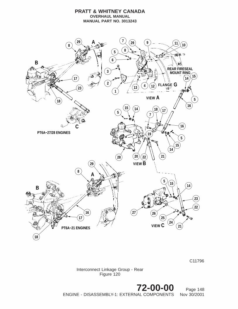
B
1716
18
PT6A−21 ENGINES VIEW C
27 2625
2421
22
23
145
15
CPT6A−27/28 ENGINES
VIEW A
VIEW B
A8
29
28 20 22 21
1415
5
16
515 14 1718
7
19
B
17
23
18
A8
29
3
2
1
6
5
29
13 4 12
8
7
FLANGE G
16
5
14 15
11 10
REAR FIRESEALMOUNT RING
9
C11796
Interconnect Linkage Group - RearFigure 120
PRATT & WHITNEY CANADAOVERHAUL MANUAL
MANUAL PART NO. 3013243
72-00-00 Page 148ENGINE - DISASSEMBLY-1: EXTERNAL COMPONENTS Nov 30/2001

(10) Unscrew nut (4) from adjuster and swivel joint assembly (21) and removeassembly from mounting bracket (23).
(11) Remove two self-locking nuts (15) and bolts (24) and separate retaining plate (22)from bracket (23).
(12) Withdraw casing and rope assembly forward through center fireseal mount ring,removing nuts (4) and seal retaining plate (12).
(13) Securely tape casing and rope assembly to a stiff board for protection. Retain partssuch as nuts, washers and bolts etc. in a bag.
(14) Overhaul parts (Ref. 76-10-00).
Key to Figure 120
1. Angle Bracket2. Bolt3. Bolt4. Control Lever Mounting Bracket5. Cotterpin6. Washer7. Bolt8. Propeller Control Cam9. Pin
10. Push-pull Rod End Clevis11. Push-pull Wire Rope Clevis12. Flange Cover13. Self-locking Nut14. Washer15. Castellated Nut16. Rod Assembly17. Fuel Control Arm Extension18. Fuel Control Unit Arm19. FCU Lever Assembly20. Spacer Sleeve (PT6A-27/28 Engines)21. Bolt (PT6A-27/28 Engines)22. Jam Nut (PT6A-27/28 Engines)23. Upper and Lower Rod Assembly (PT6A-27/28 Engines)24. Spacer Sleeve (PT6A-27/28 Engines)25. Spacer Sleeve (PT6A-27/28 Engines)26. Starting Control Lever (PT6A-27/28 Engines)27. Starting Control (PT6A-27/28 Engines)28. Fuel Control Unit (FCU - Typical) (PT6A-27/28 Engines)29. Fuel Control lever
PRATT & WHITNEY CANADAOVERHAUL MANUAL
MANUAL PART NO. 3013243
72-00-00 Page 149ENGINE - DISASSEMBLY-1: EXTERNAL COMPONENTS Nov 30/2001

15
10
7 14
15
17
18
THRUSTBEARINGCOVER
1613
129
10
6
12
38
7
65
43
21
817
14
81
11
8
2
15
DETAIL D
DETAIL B
DETAIL CDETAIL A
AB
C
D
AIRBLEEDLINK
2
C9450A
Interconnect Linkage Group - FrontFigure 121
PRATT & WHITNEY CANADAOVERHAUL MANUAL
MANUAL PART NO. 3013243
72-00-00 Page 150ENGINE - DISASSEMBLY-1: EXTERNAL COMPONENTS Nov 30/2001

Key to Figure 121
1. Castellated Nut2. Washer3. Rod End Connector4. Propeller Governor Air Bleed Link5. Bolt6. Nut7. Rod Assembly8. Cotterpin9. Wire Rope Clamp
10. Push-pull Control Rod11. Sleeve Spacer12. Bolt13. Pin14. Beta Valve Plunger15. Propeller Lever16. Sleeve Bushing17. Guide Pin Bracket18. Self-locking Nut19. Washer
PRATT & WHITNEY CANADAOVERHAUL MANUAL
MANUAL PART NO. 3013243
72-00-00 Page 151ENGINE - DISASSEMBLY-1: EXTERNAL COMPONENTS Nov 30/2001

DETAIL A
CFLANGE
DETAIL B
DETAIL C
DETAIL D
CFLANGE
29
1520
211522
4
19
23
5
7 6 24
5
1787
27
15
25
26
12
34
28 4
15
REAR FIRESEAL
9
10
11
17
515
817 12
17 8
67
1713 14
1312
18
15
16
15
CENTER FIRESEALMOUNT RING
A
B
C
SUPPORT BRACKET
REAR FIRESEALMOUNT RING
D
POST−SB1528
PRE−SB1528
15 8 25 17
C9445E
Interconnect Linkage Group - Push-pull ControlFigure 122
PRATT & WHITNEY CANADAOVERHAUL MANUAL
MANUAL PART NO. 3013243
72-00-00 Page 152ENGINE - DISASSEMBLY-1: EXTERNAL COMPONENTS Sep 10/2004
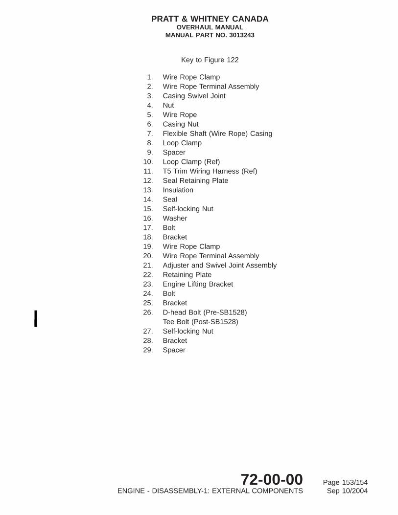
Key to Figure 122
1. Wire Rope Clamp2. Wire Rope Terminal Assembly3. Casing Swivel Joint4. Nut5. Wire Rope6. Casing Nut7. Flexible Shaft (Wire Rope) Casing8. Loop Clamp9. Spacer
10. Loop Clamp (Ref)11. T5 Trim Wiring Harness (Ref)12. Seal Retaining Plate13. Insulation14. Seal15. Self-locking Nut16. Washer17. Bolt18. Bracket19. Wire Rope Clamp20. Wire Rope Terminal Assembly21. Adjuster and Swivel Joint Assembly22. Retaining Plate23. Engine Lifting Bracket24. Bolt25. Bracket26. D-head Bolt (Pre-SB1528)
Tee Bolt (Post-SB1528)27. Self-locking Nut28. Bracket29. Spacer
PRATT & WHITNEY CANADAOVERHAUL MANUAL
MANUAL PART NO. 3013243
72-00-00 Page 153/154ENGINE - DISASSEMBLY-1: EXTERNAL COMPONENTS Sep 10/2004


ENGINE - DISASSEMBLY-2: ACCESSORY COMPONENTS
1. General
A. Personnel disassembling the engine or modules should read the Introduction Sections ofthis manual to familiarize themselves with general overhaul procedures (Ref.INTRODUCTION, Outline of Overhaul Procedures).
B. When the engine is received for overhaul, remove the air inlet screen and inspect firststage of compressor rotor for foreign object damage (FOD). Inspect engine for externaldamage, burning, corrosion, and signs of leakage. Record all observations made atthis inspection for reference during disassembly of engine, taking special notice of anydiscrepancy that might not be apparent after cleaning. Tag all affected parts to identifynature of fault. After removal from engine, submit affected parts to detailed inspectionbefore cleaning.
C. During inspection of engine, check that all externally mounted parts and accessories arecorrectly fitted. Loose or unattached components usually indicate that they have beenreplaced because of previous unserviceability. Record all discrepancies and check againstdata sheets received with engine for information relating to unserviceabilitiesencountered during service.
D. Overhaul facilities may find it more expedient to remove certain parts before others, sodisassembly sequences given in the text need not be strictly adhered to. Instructions forremoval of some standard parts, such as loop clamps and similar attaching hardware,may be repeated in areas where such parts support more than one component.
E. Disassembly is divided into three sections: DISASSEMBLY-1 through DISASSEMBLY-3.Unscheduled removal of the power section from gas generator assembly is found inDISASSEMBLY-3.
ENGINE DISASSEMBLY-1: EXTERNAL COMPONENTSENGINE DISASSEMBLY-2: ACCESSORY COMPONENTSENGINE DISASSEMBLY-3: MODULES AND MAJOR SUBASSEMBLIES
F. Seal all openings as soon as possible after removal of external parts and accessoryunits. Place each component in a separate polyethylene bag or dust-proof container,and store on suitable racks until required for overhaul. Segregate parts during storage toprevent impact damage.
G. When an engine is separated at the bolting flanges, install major assemblies inappropriate stands, cover with plastic sheeting and seal to prevent ingress of moistureand foreign material.
H. To prevent damaging seal grooves and lands, use plastic spatulas for removingpreformed packings. Damage in these areas can cause leaks due to improper seating.
I. Discard all preformed packings, tabwashers, cotterpins and gaskets immediately afterremoval, to prevent possible reuse.
PRATT & WHITNEY CANADAOVERHAUL MANUAL
MANUAL PART NO. 3013243
72-00-00 Page 101ENGINE - DISASSEMBLY-2: ACCESSORY COMPONENTS May 19/2000

2. Consumable Materials
Not Applicable
3. Special Tools
The special tools listed below are used in the following procedures.
Tool No. Name
PWC30114-09 WrenchPWC30114-16 WrenchPWC30328 PullerPWC30518 PullerPWC30556 PullerDELETED
4. Fixtures, Equipment and Supplier Tools
Not Applicable
5. Removal of Accessories
A. Remove Propeller Governor (Ref. Fig. 101)
(1) Remove four self-locking nuts (4) and washers (5) using wrench (PWC30114-09) or(PWC30114-16), as required.
(2) Separate propeller governor (1) from mounting pad (7), remove and discard gasket(6).
(3) Remove straight nipple (3), and discard preformed packing (2).
NOTE: Record part and serial number of propeller governor to ensure correctgovernor is installed at Final Assembly.
(4) Overhaul propeller governor (Ref. 61-20-00).
B. Remove Oil-To-Fuel Heater (Ref. Fig. 102)
(1) Remove oil tube assembly (9) from elbow (7) on oil-to-fuel heater (8) and elbow(10) on adapter (15) of check valve assembly.
(2) Remove bolts and retaining plate (3) from oil return adapter (1).
(3) Remove self-locking nuts and washers securing oil-to-fuel heater (8) to studs atflange G.
(4) Withdraw oil-to-fuel heater and check valve assembly (4) from studs at flange Gand adapter (1) on compressor inlet case.
PRATT & WHITNEY CANADAOVERHAUL MANUAL
MANUAL PART NO. 3013243
72-00-00 Page 102ENGINE - DISASSEMBLY-2: ACCESSORY COMPONENTS Jul 02/2004
(5) Withdraw check valve assembly from port in oil-to-fuel heater. Remove and discardpreformed packings (2 and 5).
(6) Overhaul check valve assembly, oil-to-fuel heater and attaching parts (Ref.73-10-01).
C. Remove Check Valve (minimum pressurizing) (Ref. Fig. 102)
(1) Loosen nut (11) and remove elbow (10) from adapter (15) on compressor inletcase. Remove preformed packing (13) and back-up ring (12).
(2) Remove bolts, and separate mount ring support bracket (14) and adapter (15) fromcompressor inlet case.
(3) Withdraw adapter (15) from compressor inlet case, and remove preformed packing(16).
(4) Remove retaining ring (17) from check valve sleeve (22), and withdraw check valvespring seat (18), valve spring (20) and check valve (21) from check valve sleeve(22). Remove preformed packing (19) from spring seat.
(5) Withdraw check valve housing (24) and check valve sleeve (22) from compressorinlet case using puller (PWC30518).
(6) Withdraw check valve sleeve (22) from check valve housing (24). Removepreformed packings (25) and (26) from housing and preformed packing (23) fromsleeve.
(7) Overhaul removed parts (Ref. 79-20-03).
D. Remove FCU (PT6A-21 Engines) (Ref. Fig. 103)
(1) For disconnection of fuel inlet hose, fuel pressure line, Py air pressure tube andpropeller reversing linkage controls, refer to preceding paragraphs. Remove FCU(Ref. Fig. 103).
NOTE: It may be more convenient to remove FCU and fuel pump together andseparate units on a bench.
(a) Support fuel control unit (1) and remove four self-locking nuts (2) and washers(3).
(b) Withdraw unit from studs on fuel pump (6), and remove and discard splinedcoupling (5).
(c) Remove preformed packing (7) from recess on face of fuel pump (6).
(d) Do not remove fuel control arm (9), extension (8) and serrated spacer (4) fromfuel control unit at this stage.
(e) Overhaul fuel control unit and associated parts (Ref. 73-20-00).
PRATT & WHITNEY CANADAOVERHAUL MANUAL
MANUAL PART NO. 3013243
72-00-00 Page 103ENGINE - DISASSEMBLY-2: ACCESSORY COMPONENTS May 19/2000

12
3
4
5
6
7
C7199
Propeller GovernorFigure 101
PRATT & WHITNEY CANADAOVERHAUL MANUAL
MANUAL PART NO. 3013243
72-00-00 Page 104ENGINE - DISASSEMBLY-2: ACCESSORY COMPONENTS May 19/2000

E. Remove FCU (PT6A-27/28 Engines) (Ref. Fig. 104)
(1) For disconnection of fuel inlet flexible hose, fuel pressure line, Py air pressure tube,P3 air pressure tube and propeller reversing linkage control rod, refer to precedingparagraphs. Remove FCU, as follows: (Ref. Fig. 104)
NOTE: It may be more convenient to remove fuel control unit and fuel pumptogether, and separate units on bench.
(a) Extract two cotterpins and remove castellated nuts (9), washers (8) and bolts(6). Remove interconnecting rod (10) and spacers (7), (11) and (12) from fuelcontrol unit arm and starting control arm.
NOTE: Items (6) thru (12) are not used on some PT6A-27 engine models.
(b) Support fuel control unit (1) and remove four self-locking nuts (2) and washers(3).
(c) Withdraw unit from studs on fuel pump, and remove and discard splinedcoupling (4).
(d) Remove preformed packing (5) from pump recess.
(e) Do not remove fuel control arm (14), extension (15) and serrated spacer (13)from fuel control unit (1) at this stage.
(f) Overhaul fuel control unit and associated parts (Ref. 72-20-00).
(g) Overhaul interconnect rod and associated parts (Ref. 73-10-04).
F. Remove Fuel Pump (Ref. Fig. 105)
(1) Support fuel pump (1), and remove self-locking nuts (2) and washers (3).
(2) Withdraw pump from studs on accessory gearbox (5). Discard gasket (4).
(3) Overhaul fuel pump assembly (Ref. 73-10-02).
G. Remove Starting Control (Dual Line Fuel System) (Ref. Fig. 106)
Key to Figure 101
1. Propeller Governor (Typical)2. Preformed Packing3. Straight Nipple4. Self-locking Nut5. Washer6. Gasket7. Reduction Gearbox Mounting Pad
PRATT & WHITNEY CANADAOVERHAUL MANUAL
MANUAL PART NO. 3013243
72-00-00 Page 105ENGINE - DISASSEMBLY-2: ACCESSORY COMPONENTS May 19/2000
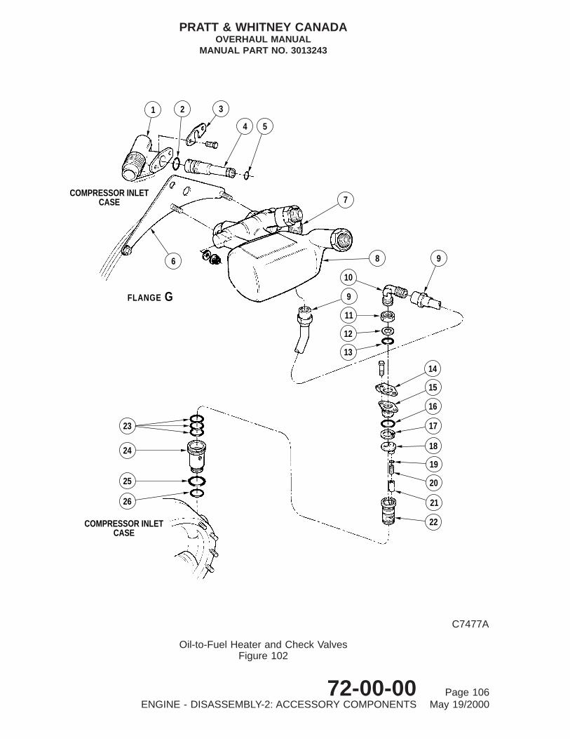
23
24
25
26
COMPRESSOR INLETCASE
14
15
16
17
18
19
20
21
22
7
8 9
10
9
11
12
13
COMPRESSOR INLETCASE
GFLANGE
6
1 2 3
4 5
C7477A
Oil-to-Fuel Heater and Check ValvesFigure 102
PRATT & WHITNEY CANADAOVERHAUL MANUAL
MANUAL PART NO. 3013243
72-00-00 Page 106ENGINE - DISASSEMBLY-2: ACCESSORY COMPONENTS May 19/2000
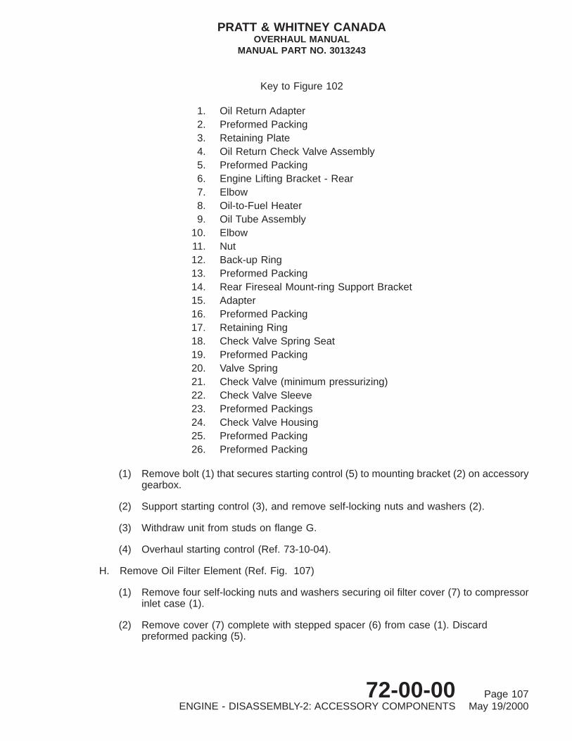
(1) Remove bolt (1) that secures starting control (5) to mounting bracket (2) on accessorygearbox.
(2) Support starting control (3), and remove self-locking nuts and washers (2).
(3) Withdraw unit from studs on flange G.
(4) Overhaul starting control (Ref. 73-10-04).
H. Remove Oil Filter Element (Ref. Fig. 107)
(1) Remove four self-locking nuts and washers securing oil filter cover (7) to compressorinlet case (1).
(2) Remove cover (7) complete with stepped spacer (6) from case (1). Discardpreformed packing (5).
Key to Figure 102
1. Oil Return Adapter2. Preformed Packing3. Retaining Plate4. Oil Return Check Valve Assembly5. Preformed Packing6. Engine Lifting Bracket - Rear7. Elbow8. Oil-to-Fuel Heater9. Oil Tube Assembly
10. Elbow11. Nut12. Back-up Ring13. Preformed Packing14. Rear Fireseal Mount-ring Support Bracket15. Adapter16. Preformed Packing17. Retaining Ring18. Check Valve Spring Seat19. Preformed Packing20. Valve Spring21. Check Valve (minimum pressurizing)22. Check Valve Sleeve23. Preformed Packings24. Check Valve Housing25. Preformed Packing26. Preformed Packing
PRATT & WHITNEY CANADAOVERHAUL MANUAL
MANUAL PART NO. 3013243
72-00-00 Page 107ENGINE - DISASSEMBLY-2: ACCESSORY COMPONENTS May 19/2000

1
23
49
8
7
5
6
C7203A
Fuel Control Unit (PT6A-21 Engines)Figure 103
PRATT & WHITNEY CANADAOVERHAUL MANUAL
MANUAL PART NO. 3013243
72-00-00 Page 108ENGINE - DISASSEMBLY-2: ACCESSORY COMPONENTS May 19/2000

(3) Using puller (PWC30556), withdraw filter element (3).
(a) Unscrew knurled nut (10) to end of thread on rod (11).
(b) Screw rod (11) into collet assembly (12), until enlarged end of rod clears colletteeth.
(c) Install puller (9) over filter housing (8) so that end of housing rests incounterbore of puller.
(d) Push rod inward until collet teeth engage behind inner bore of filter elementend cover.
(e) Carefully unscrew rod (11) to lock collet teeth in position.
CAUTION: DO NOT OVERTIGHTEN KNURLED NUT ON PULLER WHENREMOVING FILTER ELEMENT ON PT6A-27/28 (POST-SB1118) ANDALL PT6A-21 ENGINES, AS COLLET TEETH MAY CONTACTCENTER TUBE SUPPORT AND CAUSE DAMAGE.
(f) Screw in knurled nut (10) to withdraw filter element (3).
(g) Remove puller (9) and element (3) from housing (8); remove element frompuller.
(4) Remove preformed packings (2 and 4) from element (3).
(5) Overhaul removed parts (Ref. 79-20-02).
I. Oil Filter Housing Assembly (Ref. Fig. 108)
(1) Withdraw oil filter housing assembly (3) from compressor inlet case (1) using puller(PWC30328) as follows:
(a) Unscrew head (6) from nut (7).
(b) Pull open halves of head (6) at threaded end and insert opposite end of headinto oil filter housing (3); release head so that it engages behind shoulder ofhousing.
Key to Figure 103
1. Fuel Control Unit2. Self-locking Nut3. Washer4. Serrated Spacer5. Splined Coupling6. Fuel Pump7. Preformed Packing8. FCU Arm Extension9. Fuel Control Arm (Typical)
PRATT & WHITNEY CANADAOVERHAUL MANUAL
MANUAL PART NO. 3013243
72-00-00 Page 109ENGINE - DISASSEMBLY-2: ACCESSORY COMPONENTS May 19/2000

12
11
6
109
8
SHAFT EXTENSION FORLOCATION OF SHIPPING PLATE
STARTING FLOWCONTROL
7
10 6 14
13 15
FUEL PUMP
9 8 1 2 3
4
5
C7478B
Fuel Control Unit (PT6A-27/28 Engines)Figure 104
PRATT & WHITNEY CANADAOVERHAUL MANUAL
MANUAL PART NO. 3013243
72-00-00 Page 110ENGINE - DISASSEMBLY-2: ACCESSORY COMPONENTS May 19/2000

(c) Install nut (7) on head (6) to secure head in position.
(d) Operate sliding weight (8) along rod (9) to extract housing (3).
(e) Remove puller from housing (3). Discard preformed packings (2) and (5).
(2) Overhaul removed parts (Ref. 79-20-02).
J. Remove T5 Trim Wiring Harness (Ref. Fig. 109)
CAUTION: DO NOT APPLY EXCESSIVE PRESSURE ON LUGS WHEN REMOVINGTERMINAL BOLTS, BECAUSE INSULATION MATERIAL IS EXTREMELYFRAGILE.
(1) Remove bolts (8 and 9) to disconnect leads from terminal posts on terminal block.
(2) Remove self-locking nuts (7) and bolts (4).
(3) Withdraw trim harness (3) through center fireseal mount ring.
(4) Overhaul trim harness (Ref. 77-20-01).
K. Remove Ignition Regulator (Ref. Fig. 110)
(1) Support ignition regulator (1), and remove three bolts (3) and washers (2).
(2) Remove ignition regulator from accessory gearbox.
(3) Overhaul ignition regulator (Ref. 74-10-00).
Key to Figure 104
1. Fuel Control Unit (Typical)2. Self-locking Nut3. Washer4. Splined Coupling5. Preformed Packing6. Bolt7. Spacer8. Washer9. Castellated Nut
10. Interconnect Rod11. Spacer12. Spacer13. Serrated Spacer14. Fuel Control Arm15. Fuel Control Arm Extension
PRATT & WHITNEY CANADAOVERHAUL MANUAL
MANUAL PART NO. 3013243
72-00-00 Page 111ENGINE - DISASSEMBLY-2: ACCESSORY COMPONENTS May 19/2000

5432
1
C7173
Fuel PumpFigure 105
PRATT & WHITNEY CANADAOVERHAUL MANUAL
MANUAL PART NO. 3013243
72-00-00 Page 112ENGINE - DISASSEMBLY-2: ACCESSORY COMPONENTS May 19/2000

L. Remove Ignition Exciter (Ref. Fig. 111)
(1) Support ignition exciter (3), and remove self-locking nuts (5), washers (4) and bolts(1) (Pre-SB1422). Alternatively, remove nuts (8), washers (9), bolts (12) andsleeves (11) (Post-SB1422).
(2) Remove ignition exciter from mounting bracket (2).
NOTE: Mounting bracket (2) (Post-SB1337) on PT6A-21/28 engines ( BeechInstallation) has repositioned ignition exciter mounting holes (Ref. Fig.111).
(3) Support mounting bracket (2), and remove three bolts (6) and washers (7).
(4) Remove mounting bracket from accessory gearbox.
(5) Remove vibration absorber mounts (10) (Post-SB1422) from bracket (2).
(6) Overhaul removed parts (Ref. 74-10-00).
Key to Figure 105
1. Fuel Pump2. Self-locking Nut3. Washer4. Gasket5. Accessory Gearbox
PRATT & WHITNEY CANADAOVERHAUL MANUAL
MANUAL PART NO. 3013243
72-00-00 Page 113ENGINE - DISASSEMBLY-2: ACCESSORY COMPONENTS May 19/2000
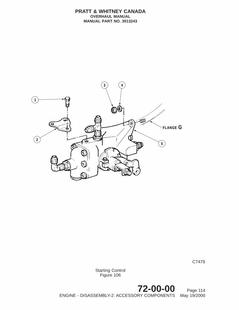
GFLANGE
5
3 4
1
2
C7479
Starting ControlFigure 106
PRATT & WHITNEY CANADAOVERHAUL MANUAL
MANUAL PART NO. 3013243
72-00-00 Page 114ENGINE - DISASSEMBLY-2: ACCESSORY COMPONENTS May 19/2000

Key to Figure 106
1. Bolt2. Mounting Bracket (Ref.)3. Self-locking Nut4. Washer5. Starting Control
PRATT & WHITNEY CANADAOVERHAUL MANUAL
MANUAL PART NO. 3013243
72-00-00 Page 115ENGINE - DISASSEMBLY-2: ACCESSORY COMPONENTS May 19/2000

1
2
8
3
4
56
7
31
9 10
11
1248
2
C9280
Oil Filter Element RemovalFigure 107
PRATT & WHITNEY CANADAOVERHAUL MANUAL
MANUAL PART NO. 3013243
72-00-00 Page 116ENGINE - DISASSEMBLY-2: ACCESSORY COMPONENTS May 19/2000

Key to Figure 107
1. Compressor Inlet Case2. Preformed Packing3. Filter Element4. Preformed Packing5. Preformed Packing6. Stepped Spacer7. Oil Filter Cover8. Oil Filter Housing9. Oil Filter Element Puller
10. Knurled Nut11. Rod12. Collet Assembly
PRATT & WHITNEY CANADAOVERHAUL MANUAL
MANUAL PART NO. 3013243
72-00-00 Page 117ENGINE - DISASSEMBLY-2: ACCESSORY COMPONENTS May 19/2000

1
2
3
4
5
2 3 4 5 1
6 7 8 9
C9281A
Oil Filter Housing Assembly RemovalFigure 108
PRATT & WHITNEY CANADAOVERHAUL MANUAL
MANUAL PART NO. 3013243
72-00-00 Page 118ENGINE - DISASSEMBLY-2: ACCESSORY COMPONENTS May 19/2000

Key to Figure 108
1. Compressor Inlet Case2. Performed Packing3. Oil Filter Housing Assembly4. Plastic Ring5. Preformed Packing6. Head7. Nut8. Weight9. Rod
PRATT & WHITNEY CANADAOVERHAUL MANUAL
MANUAL PART NO. 3013243
72-00-00 Page 119ENGINE - DISASSEMBLY-2: ACCESSORY COMPONENTS May 19/2000
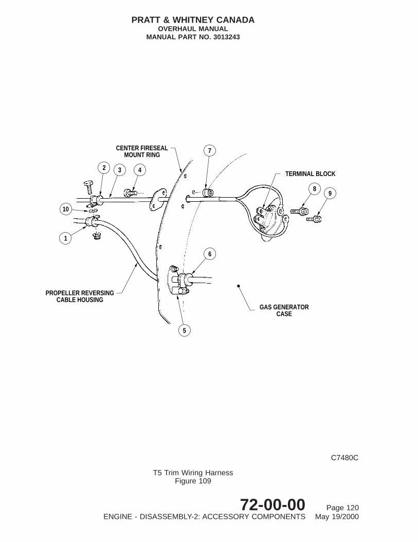
6
5
GAS GENERATORCASE
98
TERMINAL BLOCK
7
PROPELLER REVERSINGCABLE HOUSING
CENTER FIRESEALMOUNT RING
2 3 4
10
1
C7480C
T5 Trim Wiring HarnessFigure 109
PRATT & WHITNEY CANADAOVERHAUL MANUAL
MANUAL PART NO. 3013243
72-00-00 Page 120ENGINE - DISASSEMBLY-2: ACCESSORY COMPONENTS May 19/2000

Key to Figure 109
1. Loop Clamp2. Loop Clamp3. T5 Trim Harness4. Bolt5. Angle Bracket6. Loop Clamp7. Self-locking Nut8. Bolt (Alumel Terminal)9. Bolt (Chromel Terminal)
10. Spacer
PRATT & WHITNEY CANADAOVERHAUL MANUAL
MANUAL PART NO. 3013243
72-00-00 Page 121ENGINE - DISASSEMBLY-2: ACCESSORY COMPONENTS May 19/2000
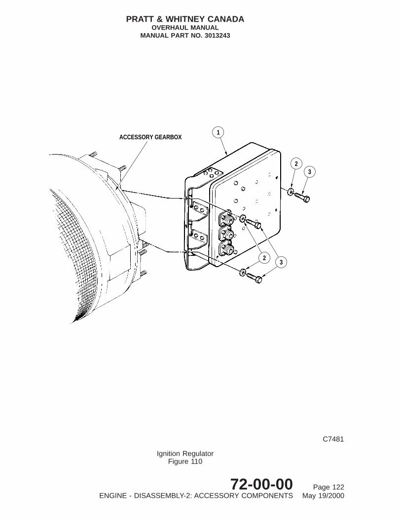
1
23
32
ACCESSORY GEARBOX
C7481
Ignition RegulatorFigure 110
PRATT & WHITNEY CANADAOVERHAUL MANUAL
MANUAL PART NO. 3013243
72-00-00 Page 122ENGINE - DISASSEMBLY-2: ACCESSORY COMPONENTS May 19/2000

Key to Figure 110
1. Ignition Regulator2. Washer3. Bolt
PRATT & WHITNEY CANADAOVERHAUL MANUAL
MANUAL PART NO. 3013243
72-00-00 Page 123ENGINE - DISASSEMBLY-2: ACCESSORY COMPONENTS May 19/2000

7 6
89
1011
9
12
7 6
3
3
4 5
POST−SB1422
2ACCESSORY GEARBOX
POST−SB1337ACCESSORY GEARBOX
21
ACCESSORY GEARBOX
7 6
3
4 5
2
1
PRE−SB1337PRE−SB1422
C8496B
Ignition Exciter InstallationFigure 111
PRATT & WHITNEY CANADAOVERHAUL MANUAL
MANUAL PART NO. 3013243
72-00-00 Page 124ENGINE - DISASSEMBLY-2: ACCESSORY COMPONENTS May 19/2000

Key to Figure 111
1. Bolt Pre-SB14222. Mounting Bracket3. Ignition Exciter4. Washer Pre-SB14225. Nut Pre-SB14226. Bolt7. Washer8. Nut Post-SB14229. Washer Post-SB1422
10. Vibration Absorber Mount Post-SB142211. Flanged Sleeve Post-SB142212. Bolt Post-SB1422
PRATT & WHITNEY CANADAOVERHAUL MANUAL
MANUAL PART NO. 3013243
72-00-00 Page 125/126ENGINE - DISASSEMBLY-2: ACCESSORY COMPONENTS May 19/2000


ENGINE - DISASSEMBLY-3: MODULES AND MAJOR SUB-ASSEMBLIES
1. General
A. Personnel disassembling the engine or modules should read the Introduction Sections ofthis manual to familiarize themselves with general overhaul procedures (Ref.INTRODUCTION, Outline of Overhaul Procedures).
B. This chapter contains overhaul procedures for a complete engine, and when applicable,overhaul procedures for approved engine modules. Overhaul procedures for an enginemodule program will be defined in Special Instructions (SIs).
C. On receipt of an engine or gas generator module (GGM) for overhaul, remove air inletscreen and examine for foreign object damage (FOD) in compressor rotor assembly.Inspect externally for damage, burning, corrosion, and signs of leakage. Record allobservations made at this inspection to provide reference during disassembly ofengine; special notice is to be made of any discrepancy which might not be apparentafter cleaning. All affected parts must be tagged to identify nature of fault and, afterremoval from engine, these parts subjected to detailed inspection before cleaning.
D. During inspection of engine, check that all externally mounted parts and accessories arecorrectly fitted. Loose or unattached components usually indicate that they have beenreplaced because of previous unserviceability. Record all discrepancies and check againstdata sheets received with engine for information relating to unserviceabilitiesencountered during service.
E. Overhaul facilities may find it more expedient to remove certain parts before others, sodisassembly sequences given in the text need not be strictly adhered to. Instructions forremoval of some standard parts, such as loop clamps and similar attaching hardware,may be repeated in areas where such parts support more than one component.
F. Disassembly is divided into three sections: DISASSEMBLY-1 through DISASSEMBLY-3.Unscheduled removal of the power section from gas generator assembly is found inDISASSEMBLY-3.
ENGINE DISASSEMBLY-1: EXTERNAL COMPONENTSENGINE DISASSEMBLY-2: ACCESSORY COMPONENTSENGINE DISASSEMBLY-3: MODULES AND MAJOR SUBASSEMBLIES
G. Seal all openings as soon as possible after removal of external parts and accessoryunits. Place each component in a separate polyethylene bag or dust-proof container,and store on suitable racks until required for overhaul. Segregate parts during storage toprevent impact damage.
H. When engine is separated at bolting flanges, install major assemblies/modules inappropriate stands, cover with plastic sheeting, and seal to prevent ingress of moistureand foreign material.
I. Use plastic spatulas when removing preformed packings to prevent possibility of scoresand scratches on seal grooves and lands; damage in these areas can produce improperseating and result in leakage.
PRATT & WHITNEY CANADAOVERHAUL MANUAL
MANUAL PART NO. 3013243
72-00-00 Page 101ENGINE - DISASSEMBLY-3: MODULES AND MAJOR SUB-ASSEMBLIES May 19/2000

J. Discard all preformed packings, tabwashers, cotterpins and gaskets immediately afterremoval, to prevent possible reuse.
2. Consumable Materials
Not Applicable
3. Special Tools
The special tools listed below are used in the following procedures.
Tool No. Name
PWC30037 SlingPWC30128-04 PullerPWC30226 Jacking ScrewsPWC30269 RingPWC30373 Pusher/PullerPWC30517 StandPWC30712 AdapterPWC30800 StandDELETEDPWC32396 Jackscrew
4. Fixtures, Equipment and Supplier Tools
Not Applicable
5. Removal of Fireseals
A. Center Fireseals
(1) Remove center fireseal as follows (Ref. Fig. 101):
(a) Remove self-locking nuts and washers (6) and bolts (7) securing top (1) andbottom (4) center fireseal mount ring support brackets (5) to integral supportbrackets (8) on gas generator case. Remove nuts, bolts and brackets (5) fromfireseal.
(b) Remove self-locking nuts (2) and bolts (3) and separate top center firesealmount ring and bottom center fireseal mount ring from gas generator case.
(c) Overhaul removed parts (Ref. 72-30-01).
B. Rear Fireseal (without wash ring)
(1) Remove fireseal from engines without compressor wash ring (Ref. Fig. 101).
(a) If necessary, remove air inlet screen (Ref. 72-20-00, DISASSEMBLY).
NOTE: Bracket (18) and attachment nuts and bolts were previously removed.
PRATT & WHITNEY CANADAOVERHAUL MANUAL
MANUAL PART NO. 3013243
72-00-00 Page 102ENGINE - DISASSEMBLY-3: MODULES AND MAJOR SUB-ASSEMBLIES Jul 02/2004

(b) Remove two self-locking nuts (13), washers (14) and bolts (12), and separatesupport bracket (15) from rear fireseal (16).
(c) Remove self-locking nuts (17) and bolts (19) from each side of upper and lowerfireseal brackets, and separate both halves of fireseal (16) and (23) from airinlet case.
NOTE: On Post-SB1441 engines, remove spacers (24) from between upperand lower fireseal brackets.
(d) Overhaul rear fireseal mount ring (Ref. 72-30-02).
C. Rear Fireseal and Compressor Wash Ring
(1) Remove fireseal from engines with compressor wash ring installed (Ref. IPC) (Ref.Fig. 101):
(a) Remove air inlet screen (Ref. 72-20-00, DISASSEMBLY).
NOTE: Bracket (18) and attachment nuts and bolts were previously removed.
(b) Remove two self-locking nuts (13), washers (14) and bolts (12), and separatesupport bracket (15) from rear fireseal (16).
(c) Remove two self-locking nuts (13), washers (14) and bolts (12), and separatesupport bracket (15) from rear fireseal (16).
(d) Remove two self-locking nuts (17) and bolts (19) from each side of upper andlower fireseal brackets, and separate both halves of fireseal (16) and (23) fromair inlet case.
NOTE: On Post-SB1441 engines, remove spacers (24) from between upperand lower fireseal brackets.
(e) Overhaul rear fireseal and wash ring (Ref. 72-30-02).
6. Separate Engine into Major Sub-Assemblies
A. Removal of Power Section (Ref. Fig. 102)
(1) Place suitable oil container below propeller reduction gearbox (7), remove oil drainplug (8) (Pre-SB1217) or magnetic chip detector (8) (Post-SB1217) and allowresidual oil to drain from gearbox.
(2) Install power section sling (PWC30037) on propeller reduction gearbox (7).
(a) Position mounting plate of sling (1) over propeller mounting flange on reductiongearbox (7), and engage dowels on flange with corresponding holes in plate.
(b) Secure sling (1) to propeller mounting flange with four socket-head cap screws(17), installed from rear of mounting flange. Tighten screws and torque 700 to770 lb.in.
PRATT & WHITNEY CANADAOVERHAUL MANUAL
MANUAL PART NO. 3013243
72-00-00 Page 103ENGINE - DISASSEMBLY-3: MODULES AND MAJOR SUB-ASSEMBLIES May 19/2000

1315
14
16
11
12
9
1
2
8
17
24
19
2019
18
17
DETAIL A
A
87
3
2GASGENERATORCASE
5
4
6
23
22
3
IGNITION CABLES
10
C41544
Center and Rear Fireseal Mount Rings and Compressor Wash RingFigure 101
PRATT & WHITNEY CANADAOVERHAUL MANUAL
MANUAL PART NO. 3013243
72-00-00 Page 104ENGINE - DISASSEMBLY-3: MODULES AND MAJOR SUB-ASSEMBLIES May 19/2000
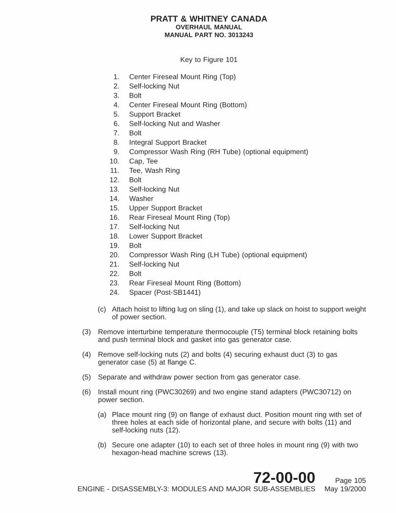
(c) Attach hoist to lifting lug on sling (1), and take up slack on hoist to support weightof power section.
(3) Remove interturbine temperature thermocouple (T5) terminal block retaining boltsand push terminal block and gasket into gas generator case.
(4) Remove self-locking nuts (2) and bolts (4) securing exhaust duct (3) to gasgenerator case (5) at flange C.
(5) Separate and withdraw power section from gas generator case.
(6) Install mount ring (PWC30269) and two engine stand adapters (PWC30712) onpower section.
(a) Place mount ring (9) on flange of exhaust duct. Position mount ring with set ofthree holes at each side of horizontal plane, and secure with bolts (11) andself-locking nuts (12).
(b) Secure one adapter (10) to each set of three holes in mount ring (9) with twohexagon-head machine screws (13).
Key to Figure 101
1. Center Fireseal Mount Ring (Top)2. Self-locking Nut3. Bolt4. Center Fireseal Mount Ring (Bottom)5. Support Bracket6. Self-locking Nut and Washer7. Bolt8. Integral Support Bracket9. Compressor Wash Ring (RH Tube) (optional equipment)
10. Cap, Tee11. Tee, Wash Ring12. Bolt13. Self-locking Nut14. Washer15. Upper Support Bracket16. Rear Fireseal Mount Ring (Top)17. Self-locking Nut18. Lower Support Bracket19. Bolt20. Compressor Wash Ring (LH Tube) (optional equipment)21. Self-locking Nut22. Bolt23. Rear Fireseal Mount Ring (Bottom)24. Spacer (Post-SB1441)
PRATT & WHITNEY CANADAOVERHAUL MANUAL
MANUAL PART NO. 3013243
72-00-00 Page 105ENGINE - DISASSEMBLY-3: MODULES AND MAJOR SUB-ASSEMBLIES May 19/2000

C7207
Removal of Power SectionFigure 102
PRATT & WHITNEY CANADAOVERHAUL MANUAL
MANUAL PART NO. 3013243
72-00-00 Page 106ENGINE - DISASSEMBLY-3: MODULES AND MAJOR SUB-ASSEMBLIES May 19/2000

(7) Lower power section into stand (PWC30800), and secure adapters (10) tomounting disks on stand with bolts (14), washers (15) and nuts (16). Tighten nutssecurely.
(8) Remove sling (1) from power section.
(9) Overhaul power section (Ref. 72-01-00).
B. Removal of Accessory Gearbox (Ref. Fig. 103)
(1) Remove oil drain plug (12) and allow residual oil to drain from accessory gearbox.Reinstall oil drain plug to prevent loss of part.
(2) Using accessory gearbox transfer tube puller (PWC30128-04), withdraw oil transfertube (21) from elbow boss inside accessory gearbox, and remove tube from bottomof compressor inlet case (22). Remove and discard preformed packings (20).
(3) Remove plug (8) from center boss in rear face of accessory gearbox and discardpreformed packing (7).
(4) Determine location of coupling shaft lock ball, at compressor rear hub coupling, byviewing through the hole in the center boss. Rotate compressor until notch inwasher at rear hub is at 3 o’clock position. This will ensure the lock ball is at the12 o’clock position on the splined end of the rear hub; preventing the ball fromdropping out of position (Ref. Fig. 103).
Key to Figure 102
1. Power Section Sling2. Self-locking Nut3. Exhaust Duct4. D-head Bolts5. Gas Generator Case6. Engine Stand7. Propeller Reduction Gearbox8. Magnetic Chip Detector9. Power Section Mount Ring
10. Engine Stand Adapter11. Bolt12. Self-locking Nut13. Hexagon-head Screw14. Bolt15. Washer16. Nut17. Socket-head Cap Screw
PRATT & WHITNEY CANADAOVERHAUL MANUAL
MANUAL PART NO. 3013243
72-00-00 Page 107ENGINE - DISASSEMBLY-3: MODULES AND MAJOR SUB-ASSEMBLIES May 19/2000
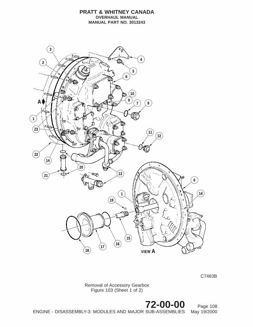
6
14
VIEW A1817
1615
19
1
13
1112
2214
20
21
56
7 89
10
4
3
2
1
23
A
C7483B
Removal of Accessory GearboxFigure 103 (Sheet 1 of 2)
PRATT & WHITNEY CANADAOVERHAUL MANUAL
MANUAL PART NO. 3013243
72-00-00 Page 108ENGINE - DISASSEMBLY-3: MODULES AND MAJOR SUB-ASSEMBLIES May 19/2000
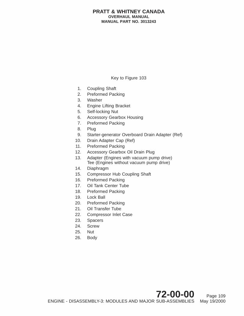
Key to Figure 103
1. Coupling Shaft2. Preformed Packing3. Washer4. Engine Lifting Bracket5. Self-locking Nut6. Accessory Gearbox Housing7. Preformed Packing8. Plug9. Starter-generator Overboard Drain Adapter (Ref)
10. Drain Adapter Cap (Ref)11. Preformed Packing12. Accessory Gearbox Oil Drain Plug13. Adapter (Engines with vacuum pump drive)
Tee (Engines without vacuum pump drive)14. Diaphragm15. Compressor Hub Coupling Shaft16. Preformed Packing17. Oil Tank Center Tube18. Preformed Packing19. Lock Ball20. Preformed Packing21. Oil Transfer Tube22. Compressor Inlet Case23. Spacers24. Screw25. Nut26. Body
PRATT & WHITNEY CANADAOVERHAUL MANUAL
MANUAL PART NO. 3013243
72-00-00 Page 109ENGINE - DISASSEMBLY-3: MODULES AND MAJOR SUB-ASSEMBLIES May 19/2000

26
25
24
DETAIL A
DETAIL B
B
24
25
26
LOCK−BALL ARRANGEMENT
A
1
15
19
C13622
Removal of Accessory GearboxFigure 103 (Sheet 2)
PRATT & WHITNEY CANADAOVERHAUL MANUAL
MANUAL PART NO. 3013243
72-00-00 Page 110ENGINE - DISASSEMBLY-3: MODULES AND MAJOR SUB-ASSEMBLIES May 19/2000

(5) Insert threaded end of accessory gearbox driveshaft puller/pusher (PWC30373)through center boss in rear face of accessory gearbox and screw into centerboreof drive gearshaft connected to coupling shaft (1). Handtighten nut on puller/pusherto remove end float.
NOTE: Two self-locking nuts and washers securing oil-to-fuel heater, enginelifting bracket (4) and accessory gearbox to studs on compressor inletcase have previously been removed.
(6) Remove remaining self-locking nut (5) and lifting bracket (4).
CAUTION: ACCESSORY GEARBOX DIAPHRAGM (14) AND HOUSING (6) ARESECURED TOGETHER BY FOUR COUNTERSUNK HEAD SCREWS ANDSELF-LOCKING NUTS. ASSUMING THE 12 O’CLOCK POSITION TOBE NO. 1, NUTS AND SCREWS SECURING DIAPHRAGM TO HOUSINGARE LOCATED AT POSITIONS NOS. 4, 8, 14 AND 18 VIEWEDCLOCKWISE. DO NOT REMOVE THESE FOUR NUTS.
(7) Remove self-locking nuts (5) securing accessory gearbox to studs on compressorinlet case (22). Remove washers (3), four spacers (PT6A-27/-28) or six spacers(PT6A-21) (23) and three support brackets.
(8) Install accessory gearbox jackscrews (PWC30226 or PWC32396) in fourflange-jacking inserts, located at each of the diaphragm-to-housing attachment nuts.Carefully, separate accessory gearbox from studs on compressor inlet case (22)by tightening on alternate jackscrews.
(9) Withdraw accessory gearbox from compressor inlet case and remove preformedpacking (2) from accessory gearbox (6) at flange G.
NOTE: If lock ball (19) drops out of locking position between compressor hubcoupling shaft (15) and coupling shaft (1) during removal of accessorygearbox, retrieve ball from No. 1 bearing housing area, or from oil scavengepassage in compressor inlet case (22), as applicable.
(10) Remove pusher/puller (PWC30373) from center boss of accessory gearbox.
(11) If oil tank center tube (17) and two oil transfer tubes are withdrawn with accessorygearbox, remove tubes from gearbox, discard preformed packings and retain tubeswith compressor inlet case (22) for subsequent overhaul of these parts.
(12) Install accessory gearbox in stand (PWC30517).
(13) Enclose plug (8) and lock ball (19) in a protective bag and tie to accessorygearbox.
(14) Overhaul accessory gearbox (Ref. 72-60-00).
(15) Overhaul gas generator assembly (Ref. 72-30-00).
PRATT & WHITNEY CANADAOVERHAUL MANUAL
MANUAL PART NO. 3013243
72-00-00 Page 111ENGINE - DISASSEMBLY-3: MODULES AND MAJOR SUB-ASSEMBLIES May 19/2000

7. Unscheduled Removal of Power Section from Gas Generator Assembly (Ref. Fig. 104)
A. Install Engine in Stand (PWC30800)
(1) Install power section sling (3) (PWC30037) on propeller reduction gearbox (15), andremove power section as follows:
(2) Place suitable oil container under reduction gearbox (15), and remove oil drain plug(14) or magnetic chip detector (14), as applicable; allow residual oil to drain fromgearbox.
(3) Disconnect coupling nut of propeller governor pneumatic (Py) line (9) at bulkheadcoupling (11) on center fireseal mount ring. Cap lines.
(4) Remove cotterpin, nut, bolt and spacer (25) securing front rod end clevis (1) topropeller reversing lever (17).
(5) Remove cotterpin, nut, bolt and washer (26) securing propeller governor interconnectrod end (2) to air bleed link (27) on propeller governor (6).
(6) Remove self-locking nut and bolt from support bracket of wire rope casing (8) atflange C.
(7) Disconnect propeller reversing linkage from bracket (7) (Pre-SB1185) on PT6A-27/28engines, as follows:
(a) Remove cotterpin, washer and straight pin (18) securing rear rod end clevis(20) to propeller control cam (19).
(b) Loosen nut on rear clamping bolt. Disengage terminal (21) and assembly of rodend clevis (20) from wire rope (22) by turning counterclockwise to free ropefrom internal thread of clamping bolt.
(c) Disconnect wire rope casing (8) from rear of front swivel joint (4) at enginelifting bracket (7).
CAUTION: HANDLE WIRE ROPE WITH CARE. STORE IN A PLASTIC BAG FORPROTECTION AGAINST CONTAMINATION AND POSSIBLEDAMAGE.
(d) Remove locknut (5) from front swivel joint (4), and withdraw link assembly andwire rope forward, and free of engine lifting bracket (7).
(8) Disconnect propeller reversing linkage from bracket (7) PT6A-27/28 (Post-SB1185)and all PT6A-21 engines.
(a) Loosen locknut (5) at rear of engine lifting bracket (7), that secures front swiveljoint (4) to lifting bracket.
(b) Remove inner nut (28) and bolt (30), and release outer nut and bolt securingswivel joint retaining plate (29) to front lifting bracket (7). Swing retaining plateout of engagement, and lift propeller reversing linkage front end clear ofslot in lifting bracket (7). Suitably support linkage.
PRATT & WHITNEY CANADAOVERHAUL MANUAL
MANUAL PART NO. 3013243
72-00-00 Page 112ENGINE - DISASSEMBLY-3: MODULES AND MAJOR SUB-ASSEMBLIES May 19/2000

(9) Remove bolts securing T5 trim harness leads to terminal posts on terminal block(10) on gas generator assembly.
(10) Remove two retaining bolts securing T5 thermocouple terminal block (10) to gasgenerator assembly. Release terminal block and gasket into gas generatorassembly.
(11) Attach hoist to lifting lug on sling (3); take up slack on hoist to support weight ofpower section.
CAUTION: DO NOT ROTATE OR DISTURB INTERSTAGE SEALING RINGS ONPOWER TURBINE STATOR HOUSING, UNLESS THEY ARE TO BEREMOVED FOR INSPECTION.
(12) Remove nuts and bolts at flange C, and separate power section from gas generatorassembly. Using sling (3), partially withdraw power section.
(13) Cap all oil transfer tubes (12) and install caps on couplings (13).
(14) Withdraw power section from gas generator assembly and install in stand (Ref.Para. 6.,A., preceding).
PRATT & WHITNEY CANADAOVERHAUL MANUAL
MANUAL PART NO. 3013243
72-00-00 Page 113ENGINE - DISASSEMBLY-3: MODULES AND MAJOR SUB-ASSEMBLIES May 19/2000

8 22
23
21
REAR FIRESEAL
INPUT LEVER
7 28
30 29
2019
18
1
25
SPACER SLEEVE
POST−SB11856
4
7
58
22 24
VIEW A
17
27 262
VIEW B
B
CONTROL LEVERMOUNTING BRACKET
FCU CONTROL ROD
11
CENTER FIRESEALMOUNT RING
10 9
12CFLANGE
17
16 1514
13
A
1 2
36
7 8
C7484
Unscheduled Removal of Power Section from Gas Generator AssemblyFigure 104
PRATT & WHITNEY CANADAOVERHAUL MANUAL
MANUAL PART NO. 3013243
72-00-00 Page 114ENGINE - DISASSEMBLY-3: MODULES AND MAJOR SUB-ASSEMBLIES May 19/2000

Key to Figure 104
1. Reversing Linkage Front Clevis2. Governor Interconnecting Rod3. Sling4. Swivel Joint (Front)5. Locknut6. Propeller Governor7. Lifting Bracket (Front) (Post-SB1185) or
Lifting Bracket (Front) (Pre-SB1185)8. Wire Rope Casing9. Propeller Governor Pneumatic Line (Py)
10. T5 Terminal Block11. Bulkhead Coupling12. Oil Transfer Tubes13. External Couplings14. Oil Drain Plug (Pre-SB1217) or
Magnetic Chip Detector (Post-SB1217)15. Reduction Gearbox16. Cap Screw (Sling)17. Propeller Reversing Lever18. Straight Headed Pin19. Propeller Control Cam20. Rod-end Clevis (Rear)21. Wire Rope Terminal22. Wire Rope23. Swivel Joint (Rear)24. Coupling Nut - Wire Rope Casing25. Bolt, Washer, Castellated Nut26. Bolt, Washer, Castellated Nut27. Air Bleed Link28. Nut29. Retaining Plate (PT6A-27/28 (Post-SB1185)
and all PT6A-21 Engines)30. Bolt
PRATT & WHITNEY CANADAOVERHAUL MANUAL
MANUAL PART NO. 3013243
72-00-00 Page 115/116ENGINE - DISASSEMBLY-3: MODULES AND MAJOR SUB-ASSEMBLIES May 19/2000


ENGINE - CLEANING
1. General
A. Personnel cleaning engine components should refer to INTRODUCTION of this manualto familiarize themselves with general overhaul procedures (Ref. Outline of OverhaulProcedures).
B. General cleaning procedures in this chapter and specific cleaning procedures in each ofthe other chapters should be used in conjunction with cleaning procedures described inP&WA Standard Practices Manual P/N 585005.
C. Certain cleaning procedures used in the manual will refer to the letter prefix SPOP, anabbreviation for Service Process Operation Procedure, followed by a control number,e.g., SPOP 209. Whenever any normal SPOP cleaning method is specified, referenceshould be made to P&WA Standard Practices Manual for detailed information.
D. In addition to the above SPOP’s, Service Process Operation Procedure numbersprefixed with the letter ‘‘U’’ are of P&WC origin, e.g. SPOP U002, PERMANENT TYPE OILFILTER CLEANING AND INSPECTION. These SPOP’s are tabulated in this chapter,to which reference will be made from other chapters using the procedures. Thecomposition and preparation of Service Process Solutions (SPS) used in the proceduresare also tabulated in this chapter. Each solution is identified by an SPS number.Materials required to prepare the process solutions are assigned a Service ProcessMaterial Control (SPMC) number.
E. Where a chapter/section/unit provides specific cleaning procedures for engine parts orassemblies, an illustration is provided for use with its appropriate table. To avoidrepetitive cleaning information on similar parts such as bearings, tubes etc., referencewill be made to this chapter/section/unit.
F. All engine parts, other than standard replacement parts such as gaskets and preformedpackings not detailed in respective tables, should be cleaned in accordance withSPOP 209. Tubes in this category must be blown through with clean, dry compressedair and examined to ensure they are unobstructed. Cap all tubes immediately aftercleaning to prevent the entry of contaminants which could affect engine operation.
G. If cleaning of tubes specified in applicable chapter is ineffective, additional cleaningshould be carried out as described in P&WA Standard Practices Manual (Ref. 72-20,SPECIFIC PARTS CLEANING).
H. Segregate bearings from other engine parts and handle carefully (Ref. 70-21, P&WAStandard Practices Manual). Clean bearings as specified in table of applicablechapter/section.
2. Consumable Materials
The consumable materials listed below are used in the following procedures.
For alternate products, suppliers and suppliers addresses refer to Consumables Material ListP/N 3043340.
PRATT & WHITNEY CANADAOVERHAUL MANUAL
MANUAL PART NO. 3013243
72-00-00 Page 201ENGINE - CLEANING May 19/2000

Item No. Name
PWC05-195 Acid, NitricPWC09-005A Compound, Universal JoiningPWC11-014 Alcohol, IsopropylPWC11-020 Solvent, Chromate ConversionPWC11-032 Solvent, DegreaserPWC11-050 Solution, Wet AbrasivePWC15-003 Compound, Corrosion Preventive Thin Film
3. Special Tools
Not Applicable
4. Fixtures, Equipment and Supplier Tools
Not Applicable
5. Cleaning
A. General
(1) The importance of engine cleaning cannot be overstated for the following reasons:
(a) Permits a thorough examination of components for the presence of serviceflaws and loss of dimensions through abrasion and wear.
(b) Removes deposits which adversely affect the efficient functioning of enginecomponents.
(c) Prepares surfaces for repair and salvage processes such as plating, weldingand painting.
(d) Removes various organic or inorganic coatings that require replacement, eitherfor inspecction of the underlaying surfaces, or to remove deteriorated coatingsunsuitable for further service.
B. General Precautions
(1) Since one reason for cleaning is to prepare parts for adequate inspection,excessive cleaning should be avoided and the following points kept in mind:
(a) In general, parts that will be subjected to visual inspection only or to magneticparticle inspection, do not require the high degree of cleanliness necessary forparts that will be subjected to fluorescent-penetrant inspection.
(b) Stains on cadmium or nickel-cadmium plated parts need not be removed sincethey do not impair magnetic-particle inspection. Scrubbing such stains mayremove the plate and necessitate replating.
(c) Oxide coatings need not be removed unless critical penetrant inspection iscalled for.
PRATT & WHITNEY CANADAOVERHAUL MANUAL
MANUAL PART NO. 3013243
72-00-00 Page 202ENGINE - CLEANING May 19/2000
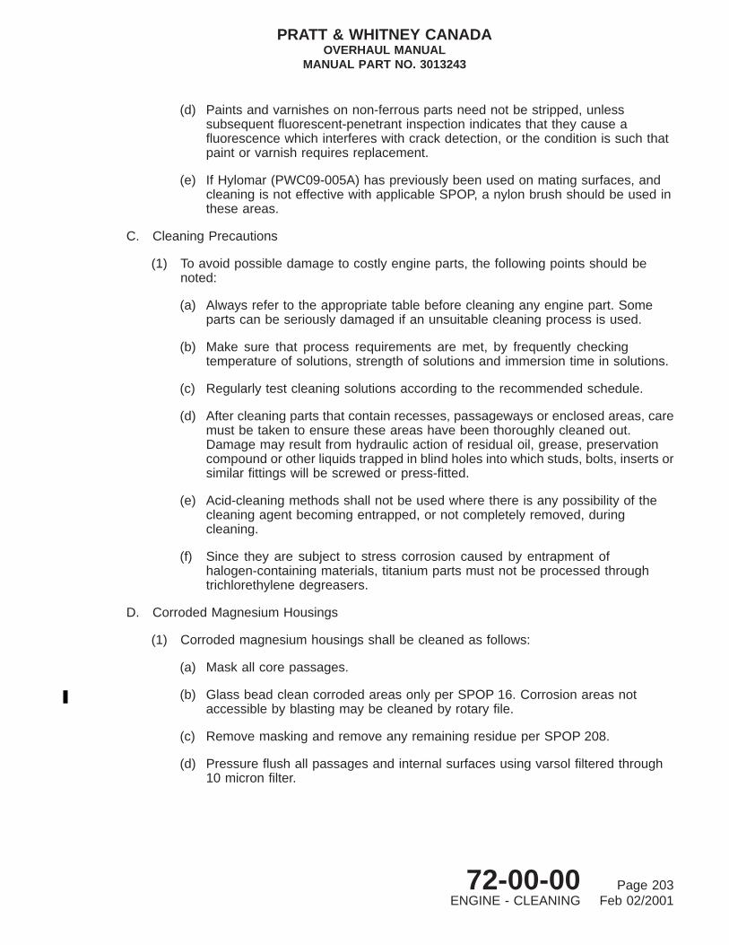
(d) Paints and varnishes on non-ferrous parts need not be stripped, unlesssubsequent fluorescent-penetrant inspection indicates that they cause afluorescence which interferes with crack detection, or the condition is such thatpaint or varnish requires replacement.
(e) If Hylomar (PWC09-005A) has previously been used on mating surfaces, andcleaning is not effective with applicable SPOP, a nylon brush should be used inthese areas.
C. Cleaning Precautions
(1) To avoid possible damage to costly engine parts, the following points should benoted:
(a) Always refer to the appropriate table before cleaning any engine part. Someparts can be seriously damaged if an unsuitable cleaning process is used.
(b) Make sure that process requirements are met, by frequently checkingtemperature of solutions, strength of solutions and immersion time in solutions.
(c) Regularly test cleaning solutions according to the recommended schedule.
(d) After cleaning parts that contain recesses, passageways or enclosed areas, caremust be taken to ensure these areas have been thoroughly cleaned out.Damage may result from hydraulic action of residual oil, grease, preservationcompound or other liquids trapped in blind holes into which studs, bolts, inserts orsimilar fittings will be screwed or press-fitted.
(e) Acid-cleaning methods shall not be used where there is any possibility of thecleaning agent becoming entrapped, or not completely removed, duringcleaning.
(f) Since they are subject to stress corrosion caused by entrapment ofhalogen-containing materials, titanium parts must not be processed throughtrichlorethylene degreasers.
D. Corroded Magnesium Housings
(1) Corroded magnesium housings shall be cleaned as follows:
(a) Mask all core passages.
(b) Glass bead clean corroded areas only per SPOP 16. Corrosion areas notaccessible by blasting may be cleaned by rotary file.
(c) Remove masking and remove any remaining residue per SPOP 208.
(d) Pressure flush all passages and internal surfaces using varsol filtered through10 micron filter.
PRATT & WHITNEY CANADAOVERHAUL MANUAL
MANUAL PART NO. 3013243
72-00-00 Page 203ENGINE - CLEANING Feb 02/2001

E. Oil Filter Cleaning and Inspection
(1) In a stainless steel container, soak filter element in carbon removing solvent (SPMCU0024) for 30 to 60 minutes at room temperature.
(2) Immerse element in cleaning solvent (SPMC U0021) in an ultrasonic cleaner (withbackflushing adapter and flush filter of 3 to 5 microns) for 1 to 3 minutes at 48 °C(118°F).
NOTE: Boiling point is 47.6°C (117.6°F).
(3) Simultaneously backflush and ultrasonic clean (SPMC U0021) the element at a flowrate of 1 to 3 gal/min at 30 psig. and at an ultrasonic frequency 25 kHz minimumfor 1 to 3 minutes at 38°C (100 °F).
NOTE: Temperature of condensed vapors is approximately 38°C (100°F).
(4) Rotate the element 180 degrees. Continue to backflush and ultrasonic cleansimultaneously (SPMC U0021) at a flow rate 1 to 3 gal/min at 30 psig. for 1 to 3minutes at 38°C (100°F) .
(5) Hold element in vapors below water jacket level for 1 to 5 minutes at 48°C (118°F).(SPMC U0021)
NOTE: Cooling water should be flowing in a constant stream through water jacket,at not more than 27°C (80°F), otherwise unnecessary losses of highlyvolatile solvent (SPMC U0021) will occur. Continue to run water throughcooling system at least 30 minutes after ultrasonic cleaner is switched off.
(6) Drain element above water jacket level 1 to 5 minutes.
(7) Use clean, dry compressed air to dry the element for 1 to 3 minutes.
(8) Inspect the element for lint deposits.
(9) Use clean, dry compressed air and/or plastic or wooden spatula to remove any lintdeposits.
(10) Remove any remaining lint deposits by soaking the element in lint dissolvingsolution (SPS U0020) for 60 minutes at room temperature. (Ref. Table 201).
(11) Flush the element in hot water 66 to 93 °C (150 to 200 °F) for 1 to 5 minutes toremove any remaining lint residue.
(12) Use clean, dry compressed air to dry the element for 1 to 3 minutes.
(13) Swab element end caps with 5 to 10% nitric acid solution (SPMC U1000) toremove any copper deposits.
(14) Pressure flush the element with cold water at room temperature.
(15) Use clean, dry compressed air to dry the element for 1 to 3 minutes.
PRATT & WHITNEY CANADAOVERHAUL MANUAL
MANUAL PART NO. 3013243
72-00-00 Page 204ENGINE - CLEANING May 19/2000
(16) Use a 10 power magnification glass to inspect the element for broken wires. Rejectthe element if broken wires are found. Sharp and deep dents, if otherwiseacceptable, should not be straightened.
(17) Do a bubble point test with the element submerged 1/2 inch below the surface ofcleaning solvent (SPMC U0021) at 22 °C (72 °F). Rotate the element slowly andsmoothly until first air bubble emerges. Reject the element if the bubble point valueis less than 3.00 inches - water gage (40 micron filter).
NOTE: Slowly increase the air pressure without creating ambient vibrations.
(18) Use clean, dry compressed air to dry the element for 1 to 3 minutes.
(19) Vibropeen cleaning date near part number.
(20) Seal the element in a clean plastic bag.
TABLE 201, SPS U0020 - Lint Dissolving Solution Preparation
SOLUTION NO.AND NAME SPOP & MATERIAL QUANTITY PREPARATION
SPS U0020Lint dissolvingsolutionSchweitzerReagent
Cupric SulfateSPMC U0020
100 grams/liter A. Dissolve SPMC U0020in water
Sodium HydroxideSPMC U0022
B. Precipitate with SPMC U0022
C. Wash precipitatethoroughly
Ammonium HydroxideSPMC U0023
D. Form saturatedsolution ofprecipitate in SPMC U0023
F. Cleaning P3 Air Filter
(1) In a stainless steel container, soak filter element in carbon removing solvent(PWC11-020) for 15 to 30 minutes at room temperature.
(2) Dip rinse element in hot water 66° to 93°C (150° to 200 °F) .
(3) Immerse element in cleaning solvent (PWC11-014) or (PWC11-032) in an ultrasoniccleaner (with backflushing adapter and flush filter of 3 to 5 microns) for 1 to 3minutes at 48°C (118°F).
NOTE: Boiling point is 47.6°C (117.6°F).
PRATT & WHITNEY CANADAOVERHAUL MANUAL
MANUAL PART NO. 3013243
72-00-00 Page 205ENGINE - CLEANING May 19/2000

(4) Simultaneously backflush and ultrasonic clean the element at a flow rate of 1 to 3gal/min at 30 psig. and at an ultrasonic frequency 25 kHz minimum for 1 to 3minutes at 38 °C (100°F).
NOTE: Temperature of condensed vapors is approximately 38 °C (100°F).
(5) Rotate the element 180 degrees. Continue to backflush and ultrasonic cleansimultaneously at a flow rate 1 to 3 gal/min at 30 psig. for 1 to 3 minutes at 38°C(100°F).
(6) Hold element in vapors below water jacket level for 1 to 5 minutes at 48°C (118°F).
NOTE: Cooling water should be flowing in a constant stream through water jacket,at not more than 27°C (80°F), otherwise unnecessary losses of highlyvolatile solvent (PWC11-014) or (PWC11-032) will occur. Continue to runwater through cooling system at least 30 minutes after ultrasonic cleaner isswitched off.
(7) Drain element above water jacket level 1 to 5 minutes.
(8) Use clean, dry compressed air to dry the element for 1 to 3 minutes.
(9) Inspect the element for lint deposits.
(10) Use clean, dry compressed air and/or plastic or wooden spatula to remove any lintdeposits.
(11) Remove any remaining lint deposits by soaking the element in lint dissolvingsolution for 60 minutes at room temperature. (Ref. Table 201).
(12) Flush the element in hot water 66 to 93°C (150 to 200°F) for 1 to 5 minutes toremove any remaining lint residue.
(13) Use clean, dry compressed air to dry the element for 1 to 3 minutes.
(14) Swab element end caps with 5 to 10% nitric acid solution (PWC05-195) to removeany copper deposits.
(15) Pressure flush the element with cold water at room temperature.
(16) Use clean, dry compressed air to dry the element for 1 to 3 minutes.
(17) Use a 10 power magnification glass to inspect the element for broken wires. Rejectthe element if broken wires are found. Sharp and deep dents, if otherwiseacceptable, should not be straightened.
(18) Do a bubble point test with the element submerged 1/2 inch below the surface ofcleaning solvent (PWC11-014) or (PWC11-032) at 22°C (72°F). Rotate the elementslowly and smoothly until first air bubble emerges. Reject the element if thebubble point value is less than 8 inches - water gage.
NOTE: Slowly increase the air pressure without creating ambient vibrations.
PRATT & WHITNEY CANADAOVERHAUL MANUAL
MANUAL PART NO. 3013243
72-00-00 Page 206ENGINE - CLEANING May 19/2000

(19) Use clean, dry compressed air to dry the element for 1 to 3 minutes.
(20) Seal the element in a clean plastic bag.
G. Vapor Honing
(1) Degrease using (SPOP 209) at room temperature.
(2) Mask as required using (SPOP 36) at room temperature.
(3) Vapor hone to a uniform matter surface (PWC11-050) at room temperature.
CAUTION: DO NOT ALLOW VAPOR HONE NOZZLE TO DWELL IN ANY ONELOCATION LONGER THAN REQUIRED.
(4) Nozzle angle at 45 to 70 degrees.
(5) Nozzle pressure 90 to 100 psi.
(6) Nozzle distance 8 inches.
(7) Water rinse at room temperature.
(8) Remove all masking material.
(9) Dry element with clean, dry compressed air.
(10) Inspect for a uniform matte surface.
(11) Preserve in corrosion preventive oil (PWC15-003) at room temperature.
TABLE 202, SPS U0090 - Wet Abrasive Slurry Preparation
SOLUTION NUMBERAND NAME
COMPOSITION (MATERAILAND MAKE UP) PREPARATION
SPS U0090Wet Abrasive Slurry
Trisodium PhosphateSPMC 15150.10 oz/gal.(PWC11-050)
A. Fill tank withwater to 75% ofoperating volume.
NovaculiteSPMC 306616 oz/gal.(PWC11-050)
B. With circulatingpump operating,slowly add requiredamount SPMC 3066
Anti-Solidifying CompundSPMC 16120.16 to 16 oz of SPMC 3066(PWC11-050)
C. Add requiredamounts of SPMC1612 and SPMC 1515.
D. Fill tank withwater to 100% ofoperating volume.
PRATT & WHITNEY CANADAOVERHAUL MANUAL
MANUAL PART NO. 3013243
72-00-00 Page 207ENGINE - CLEANING Feb 02/2001

TABLE 202, SPS U0090 - Wet Abrasive Slurry Preparation (Cont’d)
SOLUTION NUMBERAND NAME
COMPOSITION (MATERAILAND MAKE UP) PREPARATION
E. Operate circulatingpump 3 minutesminimum to mixslurry beforeoperating machine.
PRATT & WHITNEY CANADAOVERHAUL MANUAL
MANUAL PART NO. 3013243
72-00-00 Page 208ENGINE - CLEANING May 19/2000

ENGINE - INSPECTION
1. General
A. Personnel engaged on overhaul of the engine should acquaint themselves with theINTRODUCTION section of this manual (Ref. Outline of Manual OverhaulProcedures). Certain inspection procedures will refer to the P&WA Standard PracticesManual P/N 585005 (Ref. 70-30, INSPECTION).
B. Inspection procedures within this manual may refer to the letter prefix SPOP, anabbreviation for Service Process Operation Procedure, which is followed by a controlnumber, e.g., SPOP 62, STANDARD FLUORESCENT PENETRANT INSPECTION. For allSPOP inspection methods, refer to P&WA Standard Practices Manual P/N 585005.
C. Where chapter/section/unit provide specific inspection procedures for engine parts orassemblies, a figure is provided for illustration purposes. To avoid repetitive inspectioninformation on similar parts such as tubes, hoses, bearings, etc., reference will be made tothis chapter.
D. Each component must be carefully inspected by trained specialists who are capable ofdeciding, when no limits are specified, whether the part is suitable for further service,requires repair, or must be replaced. In addition to visual inspection for surface faultconditions, magnetic-particle or fluorescent-penetrant inspection must be carried outon specific parts to assist detection of cracks or material defects. If no limits are specified,cracks in any component are cause for its rejection. Where limits for wear or damageare given, it must be borne in mind that these are maximum limits. At the conclusion ofmagnetic-particle inspection, each component must be demagnetized.
E. Surface damage in the form of nicks, dents or scratches, which does not exceed thelimits specified, shall be removed with a fine stone or abrasive cloth. Local smoothingmust extend over an area at least fifteen times the depth of damage. The sharper thedamage, the more desirable it is to have the affected area smoothed. Surface finishof all repairs must be as smooth as, or smoother than the original finish, and finish marksmust follow the pattern of original machining.
2. Consumable Materials
Not Applicable
3. Special Tools
Not Applicable
4. Fixtures, Equipment and Supplier Tools
Not Applicable
PRATT & WHITNEY CANADAOVERHAUL MANUAL
MANUAL PART NO. 3013243
72-00-00 Page 301ENGINE - INSPECTION Mar 05/2004

5. Self-locking Fasteners
Engine assembly torque limits are provided in text, or referred to in Table 601 of theappropriate Chapter/Section for self-locking fasteners i.e., locknuts, helical coil inserts andself-locking bolts and screws.
TABLE 301, Minimum Acceptable Locking Torque for Self-locking Nuts and Self-locking HelicalCoil Inserts
THREAD SIZETORQUE (LB.IN.)
MIN. MAX. THREAD SIZETORQUE (LB.IN.)
MIN. MAX.
0.112-40 0.5 3 0.4375-14 16.5 100
0.112-48 0.5 3 0.4375-20 14.0 100
0.138-32 1.0 6 0.500-13 24 150
0.138-40 1.0 6 0.500-20 18 150
0.164-32 1.5 9 0.5625-12 30 200
0.164-36 1.5 9 0.5625-128 24 200
0.190-24 2.0 13 0.625-11 40 300
0.190-32 2.0 13 0.625-18 32 300
0.250-20 4.5 30 0.750-10 60 400
0.250-28 3.5 30 0.750-106 50 400
0.3125-18 7.5 60 0.875-9 82 600
0.3125-24 6.5 60 0.875-14 70 600
0.375-16 12.0 80 1.000-8 110 800
0.375-24 9.5 80 1.000-12 90 800
Self-locking fasteners are reused at overhaul, if limits specified in Table 301 can be obtainedwith mating parts identical to those used on the engine.
Or, where necessary, torque can be verified at reassembly with the locking feature fullyengaged and the fastener unseated (not in contact with any other part), so that only thefrictional hold on the screw thread is measured.
Unless otherwise specified, apply thread lubricant to all parts to be torqued, using engine oil(Ref. SB1001), or equivalent.
Torque required to overcome static friction shall not be less than the value given in theminimum breakaway torque column, Table 301.
Torque required to overcome kinetic friction shall not be greater than the value given in themaximum locking torque column, Table 301.
PRATT & WHITNEY CANADAOVERHAUL MANUAL
MANUAL PART NO. 3013243
72-00-00 Page 302ENGINE - INSPECTION May 19/2000

6. Service Time Marking (Ref. Fig. 301)
A. Life Monitoring Methods
(1) Service Life of Parts (Hours)
(a) The total operating hours (accumulated) of certain engine parts are required forrecord or warranty purposes. Engine parts in this category are marked atmanufacture with a serial number placed on a convenient and, wheneverpossible, plainly visible surface.
(b) Serialized engine parts include: combustion chamber liner, main antifrictionbearings, etc.
(c) Serialized engine accessories include: engine-driven pump, fuel control unit,compressor bleed valve, ignition exciter, etc.
(d) In order to maintain a complete record of total accumulated operating hours ofserialized parts, a method such as the Specimen Inspection Record Sheet(Ref. Fig. 301) or a card index system, must be established by the facilityoperator.
(2) Service Life of Parts (Hours/Cycles)
(a) The engine-logged service time between each overhaul in hours and cyclesshall be marked on each life-limited rotor component part listed (Ref.05-10-00 and SB1002).
(b) Applicable marking methods to ensure legibility and durability of mark, in amanner that will not affect function or service ability, are described in P&WAStandard Practices Manual (Ref. 70-11, MARKING OF PARTS.)
B. Accumulation of Nos. 1 through 4 Bearing Hours
(1) Although engine main bearings Nos. 1 through 4 and the propeller reductiongearbox bearings are retired on condition only, it is considered beneficial to maintaina record of their accumulated hours in either of the following ways:
(a) Inspection records, identifying bearings with their serial numbers.
(b) Manually vibro-peening accumulated operating hours directly on the bearingadjacent to the serial number; afterwards, lightly stone marked area toremove any raised edges.
7. Tubes and Hoses
A. Standard Instructions
(1) Tubing
PRATT & WHITNEY CANADAOVERHAUL MANUAL
MANUAL PART NO. 3013243
72-00-00 Page 303ENGINE - INSPECTION May 19/2000

C41344
Specimen Inspection Record SheetFigure 301
PRATT & WHITNEY CANADAOVERHAUL MANUAL
MANUAL PART NO. 3013243
72-00-00 Page 304ENGINE - INSPECTION May 19/2000

(a) Circumferential scratches in tubes are acceptable provided they do not exceeda 45 degree segment on circumference. Any number of scratches is permissible;these may be blended out provided depth of blend does not exceed 0.005inch.
(b) Longitudinal scratches in tubes must not exceed one-half inch in length. Anynumber of scratches is permissible.
(c) Nicks and chafing marks in tubes are acceptable and may be blended providedthey do not exceed 0.005 inch in depth. Each blended area must not exceedone-half square inch.
(d) Dents in tubes are of limited acceptability, provided there are no restrictions toflow caused by sharp edges or corners. Dents are unacceptable within oneinch of ferrule scarf-welds, or in a blended area.
(e) Minor isolated pitting is acceptable if not greater than 0.003 inch in depth.Clusters of pits should be blended out to a maximum depth of 0.005 inch.
(f) Rust and stains on tubes are acceptable if they can be removed by lightpolishing with a very mild abrasive.
(g) Examine tubes for cracks, especially at brazed joints.
(h) Examine coupling and threaded fittings for cracks or damaged threads.
(i) Check tube bores for obstructions.
(2) Hoses
(a) High pressure hoses that operate at pressures above 150 psig must berejected if any crimps or buckles are evident.
NOTE: A ‘‘crimp’’ or ‘‘buckle’’ is an abrupt change in the hose liner contourcaused when the hose is bent at too small a radius. As a result, theliner will be partially collapsed in one location. This condition, which canbe detected without removal of the metal braid, is similar to thatwhich occurs when a cardboard tube is bent. When the affected hoseis straightened, the collapsed area will expand but a change incontour remains.
(3) Metal Braid
(a) Hoses with cuts in metal braid, having more than three broken wires per plait,or more than six broken wires per linear foot, must be replaced.
(b) Replace flexible hoses where braid wires have chafed or worn to inner liner.
(4) Pressure Test
(a) Test high pressure hoses with hydraulic fluid at 3,000 psig. Maintain pressurefor a minimum of two minutes.
PRATT & WHITNEY CANADAOVERHAUL MANUAL
MANUAL PART NO. 3013243
72-00-00 Page 305ENGINE - INSPECTION May 19/2000

8. Antifriction Bearing Inspection
A. Inspection Procedures
Standard antifriction bearing inspection procedures are described in P&WA StandardPractices Manual. (Ref. 70-35, ANTIFRICTION BEARING INSPECTION.) The proceduresinclude: general precautions, inspection reports, unpacking new bearings, inspectionareas, feel tests, scriber tracing, visual inspection and bearing protection.
B. Bearing Repairs
No bearing repairs are permitted other than the repairs contained in P&WC approvedmanuals or the Anti-Friction Bearing Visual Inspection Standard P/N 3039731.
C. Aniti Friction Standard Procedures (Ref. Table 302)
NOTE: To ensure maximum accuracy when taking measurements, all componentscomprising a bearing assembly must be at the same temperature. Warming ofparts through excessive handling should be avoided.
(1) Measuring Inside and Outside Diameters
(a) Take three readings of each measurement at three equally-spaced positions,and establish the arithmetical average for the final recorded measurement.
(b) To ensure correct readings, use a dial bore gage, or a similar gage operatingon the air-gap principle; both types of instrument have to be capable ofmeasuring accurately within 0.0001 inch with a gage force not exceeding fourounces.
(c) Reject any bearing assembly having I.D. or O.D. dimensions outside the limitsspecified in Table 302, for the particular bearing.
NOTE: Since the foregoing method of measurement is accurate only toapproximately 0.0005 inch, this margin of error should be taken intoconsideration before rejecting an otherwise serviceable bearingassembly.
TABLE 302, Bearing Inspection Limits
BEARINGLOCATION(NOTE 1)
BEARINGASSEMBLYPART NO.
INNER RACEI.D. (in.)
OUTERRACE O.D.
(in.)
RACE MIN.HARDNESS
VALUE(ROCKWELL)
(NOTE 2) REMARKS
AccessoryGearbox
301067430280053031724
3101636-01
0.94490.9453
1.65321.6535
C58 TwelveBearings
(max.)
PRATT & WHITNEY CANADAOVERHAUL MANUAL
MANUAL PART NO. 3013243
72-00-00 Page 306ENGINE - INSPECTION May 19/2000

TABLE 302, Bearing Inspection Limits (Cont’d)
BEARINGLOCATION(NOTE 1)
BEARINGASSEMBLYPART NO.
INNER RACEI.D. (in.)
OUTERRACE O.D.
(in.)
RACE MIN.HARDNESS
VALUE(ROCKWELL)
(NOTE 2) REMARKS
1 300719430280033033459
3101864-01
1.18091.1811
2.83432.8346
C58
2 and 3 300614630280043031717
3102455-01
1.57461.57481.57461.5748
2.67692.67722.67692.6772
C61C60
4 30092433028006
3101635-01
1.18091.1811
2.83432.8346
C58
2nd StageCarrier
300347630280073031714
3102454-01
3.14963.1500
4.36974.3701
C58C57
ThrustBearing
300714730280083101795
3102227-01
2.95242.9528
5.11765.1181
C58
NOTE: 1. Refer to INTRODUCTION.
NOTE: 2. Race hardness testing necessary only when overheating of bearing assemblysuspected. Readings up to one Rockwell point below minimum value acceptable tocompensate for instrument error and variation.
9. Gears and Gearshaft Inspection
NOTE: The following general inspection procedures should be used for all gears andgearshafts except where more specific inspection procedures/data are detailed inthe relevant chapters of this manual.
A. Visual Inspection Of Gear Teeth
CAUTION: HANDLE COMPONENTS WITH EXTREME CARE. ALWAYS WEARCLEAN SYNTHETIC RUBBER OR LINT-FREE COTTON GLOVESDURING HANDLING. PROTECT GEARS AND GEARSHAFTS WITHENGINE OIL, AND PLACE IN CLEAN PLASTIC BAG OR CLEAN SUITABLECONTAINER IF NOT REQUIRED FOR IMMEDIATE USE.
(1) Spalling: Reject if evident.
(2) Surface Pitting: Accept pitting damage up to 0.005 inch deep and 0.010 inchdiameter, provided no more than five pits are found in 0.250 inch diameter area.
PRATT & WHITNEY CANADAOVERHAUL MANUAL
MANUAL PART NO. 3013243
72-00-00 Page 307ENGINE - INSPECTION May 19/2000

(3) Raised Material and Sharp Edges: Stone to remove.
(4) Localized Nicks, Dents or Scratches: Remove sharp edges and blend damage upto 0.003 inch deep and 0.010 inch wide, provided a minimum 80% of total toothsurface contact pattern remains. Polish to restore original surface finish and maintaintooth profile.
(5) Uneven Tooth Surface Contact Pattern: Damage up to 0.003 inch deep isacceptable, provided a minimum of 80% of the total tooth surface contact patternremains. Polish to restore original surface finish and maintain tooth profile.
B. Magnetic Particle Inspect
(1) Inspect gears and gearshafts using appropriate SPOP (Refer to relevant chapter forspecific SPOP callout).
C. Inspect Carbon Seal Face
(1) Localized Nicks, Dents or Scratches: Damage up to 0.002 inch deep without highspots and not extending across more than 50% of sealing face is acceptable. Lapface if damage exceeds limits.
(2) Runout: Runout must be 0.001 inch FIR in relation to datums unless otherwisestated.
(3) Flatness: Flatness must be within two helium light bands. Lap face (Ref. Repair) ifflatness exceeds limits.
(4) Surface Finish: Surface finish must be within 4 micro-inches or better.
D. Inspect Splines
(1) Surface Pitting: Accepts pitting damage up to 0.005 inch deep by 0.015 inchdiameter, provided no more than five pits are found in 0.250 inch diameter area.
(2) Raised Material and Sharp Edges: Stone to remove.
(3) Localized Nicks, Dents or Scratches: Remove sharp edges and blend damage upto 0.005 inch deep and 0.010 inch wide, provided a minimum 80% of total splinesurface contact pattern remains. Polish to restore original surface finish and maintainspline profile.
(4) Galling: Remove damage up to 0.005 inch deep by polishing to restore originalsurface finish. Maintain original spline profile.
(5) Wear, Uneven Spline Surface Contact Pattern: Damage up to 0.005 inch deep isacceptable, provided a minimum of 80% of the total spline surface contact patternremains. Polish to restore original surface finish and maintain spline profile.
E. Inspect Threads
(1) Surface Pitting: Accept pitting damage up to 0.003 inch deep by 0.010 inchdiameter, provided no more than three pits are found in 0.250 inch length.
PRATT & WHITNEY CANADAOVERHAUL MANUAL
MANUAL PART NO. 3013243
72-00-00 Page 308ENGINE - INSPECTION May 19/2000

(2) Raised Material and Sharp edges: Stone to remove.
(3) Localized Nicks, Dents or Scratches: Remove sharp edges and blend damage upto 0.005 inch deep and 0.010 inch wide, provided a minimum 90% of total threadcontact pattern remains. Polish to restore original surface finish and maintain originalthread profile.
(4) Galling: Remove damage up to 0.005 inch deep by polishing to restore originalsurface finish. Maintain original thread profile.
(5) Wear: Damage up to 0.003 inch deep is acceptable.
F. Inspect Retaining Ring Grooves and Slots
(1) Surface Pitting: Accept pitting damage up to 0.005 inch deep by 0.015 inchdiameter, provided no more than five pits are found in 0.250 inch diameter area.
(2) Raised Material and Sharp Edges: Stone to remove.
(3) Localized Nicks, Dents or Scratches: Remove sharp edges and blend damage upto 0.005 inch deep and 0.010 inch wide. Polish to restore original surface finish.
(4) Wear: Damage up to 0.005 inch deep is acceptable.
G. Inspect Oil Hole(s)
(1) Ensure holes are clean and free of any obstructions.
H. Inspect Gearshaft Bearing Diameters
NOTE: The following inspection is for damage on bearing diameters having directcontact with balls/rollers of bearing.
CAUTION: DIAMETER(S) IN DIRECT CONTACT WITH BEARING(S) HAVING NOINNER RACE MUST NOT BE PLATED.
(1) Surface Pitting: Accept pitting damage up to 0.005 inch deep by 0.015 inchdiameter, provided no more than five pits are found in 0.250 inch diameter area.
(2) Raised Material and Sharp Edges: Stone to remove.
(3) Localized Nicks, Dents or Scratches: Remove sharp edges and blend damage upto 0.005 inch deep and 0.010 inch wide, provided damage is 0.050 inch minimumapart. Polish to restore original surface finish and maintain geometric tolerances.
(4) Scratches or Scoring: Remove sharp edges and blend damage up to 0.005 inchdeep and 0.010 inch wide, provided damage is 0.050 inch minimum apart. Polishto restore original surface finish and maintain geometric tolerances.
I. Inspect Remaining Surfaces
(1) Surface Pitting: Accept minor pitting damage up to 0.005 inch deep by 0.015 inchdiameter, provided no more than five pits are found in 0.250 inch diameter area.
PRATT & WHITNEY CANADAOVERHAUL MANUAL
MANUAL PART NO. 3013243
72-00-00 Page 309ENGINE - INSPECTION May 19/2000

(2) Raised Material and Sharp Edges: Stone to remove.
(3) Localized Nicks, Dents or Scratches: Remove sharp edges and blend damage upto 0.010 inch deep and 0.010 inch wide. Polish to restore original surface finish andmaintain geometric tolerances.
J. Inspect All Surfaces
(1) Remove surface stains, corrosion deposits up to 0.001 inch deep using SPOP 16 .Prior to wet glass bead blasting, mask the following areas:
(a) Diameters in direct contact with balls/rollers of bearing.
(b) Carbon seal contact face(s).
(c) Oil seal(s) diameter(s).
(d) Oil hole(s).
PRATT & WHITNEY CANADAOVERHAUL MANUAL
MANUAL PART NO. 3013243
72-00-00 Page 310ENGINE - INSPECTION May 19/2000

ENGINE - REPAIR
1. General
A. Personnel engaged in overhaul of the engine should acquaint themselves with theINTRODUCTION section of this manual to familiarize themselves with general overhaulprocedures (Ref. Outline of Overhaul Procedures).
B. Specific repairs are provided in certain chapters of the manual; repairs common in manyareas of the engine are described in this chapter, e.g., helical coil inserts, oversize studholes, etc. Standard repairs should be used where specified (Ref. P&WA StandardPractices Manual P/N 585005).
C. Many repair procedures refer to the letter prefix SPOP, an abbreviation for ServiceProcess Operation Procedure, which is followed by a control number, e.g., SPOP 21,CADMIUM PLATE. Whenever any repair SPOP method is required, refer to P&WAStandard Practices Manual P/N 585005 for detailed information.
D. These instructions have been written with the understanding that all components havebeen cleaned, inspected and tagged to indicate suitability for further service, requirerepair or must be replaced.
E. Where specific procedures include inspection using either fluorescent-penetrant ormagnetic-particle methods, reference must be made to the appropriate table in Inspectionfor detailed instructions.
2. Consumable Materials
The consumable materials listed below are used in the following procedures.
For alternate products, suppliers and suppliers addresses refer to Consumables Material ListP/N 3043340.
Item No. Name
PWC05-101 Cloth, Abrasive Aluminum OxidePWC05-108 Flux, Silver Brazing, High TemperaturePWC07-016 Thinner, Surface SealantPWC07-017 Coating, Surface SealantPWC07-037 Touch-up Kit, Surface SealantPWC08-005 Filler Metal, Brazing, SilverPWC09-004 Sealant, Silicone RubberPWC11-009 Alcohol, Ethyl DenaturedPWC11-016 Perchlorethylene (Inhibited)PWC11-023 Solvent, Cleaning
3. Special Tools
Not Applicable
PRATT & WHITNEY CANADAOVERHAUL MANUAL
MANUAL PART NO. 3013243
72-00-00 Page 401ENGINE - REPAIR Jul 02/2004

4. Fixtures, Equipment and Supplier Tools
Not Applicable
5. Restoration of Protective Coating
A. Stripping of Surface Sealant (Araldite) Coating from Magnesium Components
(1) Degrease component per SPOP 209.
CAUTION: MAKE SURE STRIPPER IS FREE OF WATER TO AVOID CORROSIONOF MAGNESIUM PART.
(2) Strip surface sealant (Araldite), epoxy primer and aluminized paint per SPOP 260.
(3) If local spots persist on component, mask as required, and remove by dryplastic blast per SPOP 19.
(4) Touch-up bare metal per SPOP 41.
NOTE: Complete immersion in tank of dichromate solution may be required if thecomponent has been extensively dry pastic blasted to remove the oldcoating.
B. Application of Surface Sealant (Araldite) on Magnesium Components
NOTE: It is preferable that shop temperature be between 16° to 21 °C (61° to 70 °F)with a relative humidity of 35 to 75 % during application of surface sealant.
(1) Clean component per SPOP 209.
(2) Touch-up bare metal per SPOP 41.
(3) Mask studs, pins, helical coil inserts, jacking inserts and internal sleeves perSPOP 36.
(4) Bake for 20 minutes minimum at 143° to 154 °C (290° to 310 °F).
(5) Cool down to room temperature and make sure that masking is still in place.
NOTE: Use thinner (PWC07-016) as required to obtain proper viscosity for thespray gun.
(6) Apply, as soon as possible, surface sealant (PWC07-017) to make sure thatmoisture is not absorbed.
NOTE: Mix per manufacturer’s recommendations and apply coat (total thicknessof 0.00025 to 0.00045 inch).
(7) Air dry for 15 to 30 minutes at room temperature in a dust free atmosphere.
(8) Cure first coat for 15 minutes at 195° to 200 °C (385° to 400 °F).
PRATT & WHITNEY CANADAOVERHAUL MANUAL
MANUAL PART NO. 3013243
72-00-00 Page 402ENGINE - REPAIR Aug 16/2002

(9) Bake final coat for 45 to 60 minutes at 195° to 200 °C (385 to 400 °F).
NOTE: Air dry 15 to 30 minutes between multiple coats.
(10) Restore epoxy primer and aluminized enamel paint per SPOP 148 except, bakeenamel paint for 45 minutes at 143° to 149 °C (290° to 300 °F).
(11) Remove masking.
C. Touch-up of Araldite Coated Components
NOTE: This touch-up procedure is to be done to reworked areas not exceeding 5 % ofthe total surface of the component. If this limit is exceeded, strip and recoatentire component with Araldite coating per Subparas. A. and B.).
(1) Degrease component per SPOP 209 or locally degrease reworked area perSPOP 208.
(2) Touch-up bare metal per SPOP 41.
(3) Mask studs, pins, helical coil inserts, jacking inserts and internal sleeves perSPOP 36.
(4) Prepare two-part epoxy coating (PWC07-037) by mixing one part by volume ofresin with one part by volume of catalyst.
NOTE: Coating may be applied by either a brush or spray gun. Use thinner(PWC07-016) as required to obtain proper viscosity for the spray gun.
(5) Bake for 20 minutes minimum at 143° to 154 °C (290° to 310 °F).
(6) Cool down and verify masking at room temperature.
(7) Touch-up component as soon as possible with surface sealant (PWC07-037) tomake sure that moisture is not absorbed.
NOTE: Apply one coat (0.0004 to 0.0007 inch).
(8) Air dry for 20 minutes at room temperature.
(9) Bake for one hour at 93° to 121 °C (200° to 250 °F).
(10) Locally restore epoxy primer and aluminized enamel paint on reworked areas perSPOP 148 except, bake enamel paint for 45 minutes at 143° to 149 °C (290° to300 °F).
6. General Procedures
A. Oversize studs are installed as replacements for those parts which are stretched, looseor have damaged threads. Should a stud that is already oversize require replacement,use the next oversize stud. Use the correct stud drivers to insert new studs and torque tovalues given (Ref. 70-52, P&WA Standard Practices Manual). The Illustrated PartsCatalog for the engine contains part numbers and location of studs.
PRATT & WHITNEY CANADAOVERHAUL MANUAL
MANUAL PART NO. 3013243
72-00-00 Page 403ENGINE - REPAIR Aug 16/2002

B. When threads of a stud hole are damaged beyond dimensions suitable for a maximumoversized stud, they may be repaired using a helical coil insert (Ref. Para. 7., following).The Parts Catalog may provide part numbers and locations of suitable helical coilinserts. Before other methods of replacing studs are attempted, e.g., standard insert orsolid inserts, ensure sufficient material remains around the repair so as not to impairthe integrity of cavity walls, etc.
7. Damaged Stud Holes
A. Repair Damaged Stud Holes
(1) Check damaged hole is suitable for repair.
(2) Install new insert (Ref. SPOP415).
8. Replacement of Helical Coil Insert
A. Replace Damaged Inserts
(1) Remove unserviceable insert using recommended extracting tool.
(2) Install new insert (Ref. SPOP415).
PRATT & WHITNEY CANADAOVERHAUL MANUAL
MANUAL PART NO. 3013243
72-00-00 Page 404ENGINE - REPAIR Jul 02/2004

9. Weld Repair
A. Welding Procedures
(1) Recommended welding procedures are described in the INTRODUCTION sectionof this manual, and details of procedures to be followed during welding of engineparts are given in 70-42, P&WA Standard Practices Manual.
B. Weld Repairs
(1) Unless otherwise directed, stress relief after welding is not required.
(2) A new weld shall not be applied over an existing weld repair.
(3) Weld beads shall be dressed to within 0.005 inch of adjacent parent metal. Noundercutting is permissible
(4) The width of weld bead shall not exceed 0.150 inch at any point.
10. Loop Clamps
A. Replacement of Damaged Loop Clamp Grommets (Ref. Fig. 401)
(1) Soften cement between grommet and clamp with cleaning solvent (PWC11-023),and remove grommet and all residual cement from clamp.
(2) Roll new grommet around suitable rod to obtain required inside diameter (dia. A).Exercise care when forming loop to avoid damaging grommet.
(3) Wipe mating surfaces of clamp and grommet with a clean, lint-free cloth moistenedin cleaning solvent (PWC11-023), to ensure clean and dry contact areas forapplication of cement.
(4) Apply a thin film of cement (PWC09-004) to designated areas on loop clamp andgrommet.
(5) Position grommet in loop clamp, align as shown and press cemented surfacestogether. Allow cement to cure for 24 hours at room temperature.
(6) Check adhesion of grommet to loop clamp. If unsatisfactory, repeat steps (1)through (5).
11. Copper Plating
For copper plating (PS 304) and service process solutions refer to Standard PracticesManual 70-44-02.
PRATT & WHITNEY CANADAOVERHAUL MANUAL
MANUAL PART NO. 3013243
72-00-00 Page 405ENGINE - REPAIR Aug 16/2002
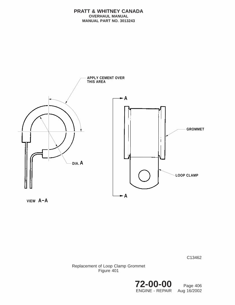
APPLY CEMENT OVERTHIS AREA
DIA.
VIEW
GROMMET
LOOP CLAMP
A
A
A−AA
C13462
Replacement of Loop Clamp GrommetFigure 401
PRATT & WHITNEY CANADAOVERHAUL MANUAL
MANUAL PART NO. 3013243
72-00-00 Page 406ENGINE - REPAIR Aug 16/2002

12. Stainless Steel Oil Tubes
A. Repair Oil Tubes With Dents (Area a, Fig. 402)
(1) Stainless steel oil tubes with round-bottom dents found in Area a can be repairedas follows.
NOTE: Do not remove ferrules.
(2) Insert a brass rod of the appropriate size into the tube damaged area and securethe other end of the brass rod in a vise or other suitable holder. The brass rodshould be the largest diameter that will fit into the tube without damaging the ferrule.
(3) Use a suitable smooth-faced hammer to lightly tap the tube outer wall surface tore-shape the tube to its original shape. Rework the damaged areas of the tube insmall increments with light hammer blows. Attempts to rework large areas with singlehammer blows could result in the tube being rejected.
(4) Make sure that the ferrule or other areas of the tube were not damaged duringrework.
(5) Locally polish the reworked area.
WARNING: COMPRESSED AIR CAN CAUSE SERIOUS INJURY. MAKE SURE THETUBE IS TESTED IN A MANNER SO THAT PERSONNEL AREPROTECTED IN THE EVENT OF A TUBE FRACTURE OR FAILURE.
(6) Pressure test the tube at 150 to 200 psi. No leakage is permitted.
(7) Clean the tube assembly (Ref. Chapter 79-20-01, CLEANING).
B. Repair Oil Tubes With Damaged Ferrules Or Dents (Area b, Fig. 402)
(1) Stainless steel oil tubes dented within 0.750 inch from the ferrule (Area b), can berepaired without removing the ferrule, provided that the ferrule is not damaged. Ifthe ferrule is not damaged, rework the tube to remove dents in Area b, (Ref. Para. A.,steps (2) to (6)).
(2) Only if the ferrule is damaged, or if replacement of it is necessary for access toperform the repair, proceed as follows:
(a) Locally heat the ferrule until able to remove it from the tube. Discard thedamaged ferrule or retain undamaged ferrule.
(b) Strip the remaining silver braze using SPOP 305.
(c) Rework the damaged tube to remove dents in Area b (Ref. Para. A., steps (2)to (5).
(d) Prepare ferrule and tube for brazing according to AMS 2664:
PRATT & WHITNEY CANADAOVERHAUL MANUAL
MANUAL PART NO. 3013243
72-00-00 Page 407ENGINE - REPAIR Aug 16/2002

CAUTION: DO NOT HIGHLY POLISH SURFACES TO BE JOINED. DO NOTUSE ALUMINUM OXIDE TYPE ABRASIVES SUCH AS CROCUSCLOTH TO POLISH SURFACES.
1 Lightly clean OD of tube and ID of ferrule with No. 320 grit silicon carbidecloth PWC05-101. Degrease with PWC11-009.
2 Apply sufficient flux PWC05-108 to completely coat joining surfaces.
(e) Install new or undamaged ferrule on the tube in its original position.
(f) Support the assembled tube in its required length and alignment.
(g) Braze the ferrule on the tube according to AMS 2664 using torch-braze (neutralflame) with brazing rod (PWC08-005).
(h) Rinse in clean hot water to remove all traces of flux.
(i) Inspect brazed area for continuity of braze all around the ferrule.
WARNING: COMPRESSED AIR CAN CAUSE SERIOUS INJURY. MAKE SURETHE TUBE IS TESTED IN A MANNER SO THAT PERSONNEL AREPROTECTED IN THE EVENT OF A TUBE FRACTURE ORFAILURE.
(j) Pressure test at 150 to 200 psi. No leakage is permitted.
(3) Clean the tube assembly (Ref. Chapter 79-20-01 or 79-20-04, CLEANING).
PRATT & WHITNEY CANADAOVERHAUL MANUAL
MANUAL PART NO. 3013243
72-00-00 Page 408ENGINE - REPAIR Aug 16/2002

BRAZE FERRULE
ab b0.750 0.750
C80605
Repair of Stainless Steel Oil Tube (Typical)Figure 402
PRATT & WHITNEY CANADAOVERHAUL MANUAL
MANUAL PART NO. 3013243
72-00-00 Page 409/410ENGINE - REPAIR Aug 16/2002


FINAL ASSEMBLY - 1: ENGINE ASSEMBLY
1. General
A. Personnel engaged in final assembly of the engine should refer to the INTRODUCTIONsection of this manual to familiarize themselves with general overhaul procedures (Ref.Outline of Manual Overhaul Procedures).
B. Final assembly is divided into three sections: FINAL ASSEMBLY-1 through FINALASSEMBLY-3.
ENGINE FINAL ASSEMBLY-1: ENGINE ASSEMBLYENGINE FINAL ASSEMBLY-2 : ACCESSORY AND EXTERNAL COMPONENTSENGINE FINAL ASSEMBLY-3 : FINAL CHECKS
C. To ensure that major sub-assemblies, accessories, external components and theirassociated parts are correctly grouped, assembled and installed to suit the engine modeland service bulletin (S.B.) standard, reference should be frequently made to theIllustrated Parts Catalog and applicable S.B’s.
D. Do not allow loop clamps to move cables from their natural contour when tighteningattachment bolts, as chafing of cable will result.
E. Subassembly instructions for major components are described in the relevantChapter/Section/Unit, as applicable for that component.
2. Consumable Materials
The consumable materials listed below are used in the following procedures.
For alternate products, suppliers and suppliers addresses refer to Consumables Material ListP/N 3043340.
Item No. Name
PWC06-002 Petrolatum, WhitePWC09-022 Compound, Jointing
3. Special Tools
The special tools listed below are used in the following procedures.
Tool No. Name
PWC30037 SlingPWC30373 Pusher/Puller
4. Fixtures, Equipment and Supplier Tools
Not Applicable
PRATT & WHITNEY CANADAOVERHAUL MANUAL
MANUAL PART NO. 3013243
72-00-00 Page 501FINAL ASSEMBLY - 1: ENGINE ASSEMBLY Jul 02/2004

5. Assembly of Engine Major Sub-Assemblies
A. Installation of Accessory Gearbox Assembly to Gas Generator Assembly (Ref. Fig. 503)
(1) With accessory gearbox assembly and gas generator assembly assembled tostandard detailed in Chapters 72-60-00 and 72-30-00 respectively, and with gasgenerator assembly mounted in stand (Ref. 72-30-00), proceed as follows:
(a) Remove storage protection or sealing materials from rear face of gas generatorassembly and front face of accessory gearbox, in preparation for assembly.
(b) Ensure that transfer tubes and associated preformed packings are installedcorrectly on rear face of inlet case and have not been disturbed sinceassembly of gas generator assembly.
(c) Make sure that ball-lock spring, plug and associated parts are in position incompressor hub coupling shaft (15).
(d) Slowly rotate compressor until hole in compressor hub coupling shaft (15) is at12 o’clock position. Place lock ball (19) in hole, and pack with petrolatum(PWC06-002)) to retain ball during following assembly (Ref. Fig. 503, Sheet 2).
(e) Install preformed packings (16) and (18) on oil tank center tube (17), and inserttube into centerbore of inlet case.
(f) Install preformed packing (2) on spigot of accessory gearbox diaphragm (14).
(g) Lift gearbox onto gas generator assembly, aligning dowel in diaphragm with holein compressor inlet case (22). Locate gearbox on inlet case studs and aligncoupling shaft, oil transfer tubes and oil tank center tube, taking care not todamage preformed packings.
(h) Insert pusher tool (PWC30373) through rear of gearbox housing at plug (8)location. Engage threaded end of pusher with threaded drive gearshaft,connected to input coupling shaft (1), and screw body of pusher into gearboxhousing. Back-off nut on pusher sufficiently to allow full forward travel of pusherfor engagement of coupling shaft (1) with lock ball (19) on compressor rearhub coupling (15).
CAUTION: IF LOCK BALL BECOMES DISLODGED FROM COMPRESSOR HUBCOUPLING, BALL MUST BE RETRIEVED BEFORE ASSEMBLYCONTINUES.
(i) Apply hand-pressure on pusher tool to engage lock ball (19). When ball isproperly engaged, end-float on drive gearshaft and input coupling shaft willbe reduced to a slight fore and aft movement.
(j) Install spacers, brackets and plain washers (Ref. Figs. 501 and 502). Install aself-locking nut on each of 16 studs. Tighten nuts in a diametric sequence andtorque 32 to 36 lb.in.
(k) Remove pusher tool from drive gearshaft and gearbox.
PRATT & WHITNEY CANADAOVERHAUL MANUAL
MANUAL PART NO. 3013243
72-00-00 Page 502FINAL ASSEMBLY - 1: ENGINE ASSEMBLY Jul 02/2004

(l) Install preformed packing (7, Fig. 503) on plug (8). Install plug and torque 150to 160 lb.in.
(m) Install preformed packings (20) on oil transfer tube (21); insert assembly inboss at 7 o’clock position at bottom of inlet case.
6. Power Section
A. Installation of Power Section on Gas Generator Assembly (Ref. Fig. 504)
(1) With power section and gas generator assembly assembled to standard detailed inChapters 72-01-00 and 72-30-00 respectively, and gas generator assemblymounted in a vertical position in stand (Ref. 72-30-00), proceed as follows:
(a) Place overhauled power section in stand (Ref. 72-01-00, SUB-ASSEMBLY) intoa vertical position.
(b) Locate sling (2) (PWC30037) on propeller mounting flange, and engage dowelsin flange bolt holes. Secure sling to flange with four socket-head cap screws(1).
(c) Attach hoist to nose ring on sling to take weight of power section, and removebolts securing mount ring to exhaust duct.
(d) Hoist power section clear of mount ring and stand.
(e) Ensure that protective covers installed during overhaul of power section andgas generator assembly are removed.
(f) Check that gas generator case flange C, and power section exhaust ductflange C, are clean, free from nicks, scratches, dents and other damagelikely to affect sealing efficiency. Smear a thin layer of compound (PWC09-022)on exhaust flange before assembly.
(g) Install interstage sealing ring(s) on power turbine stator housing:
1 Two ring Pre-SB1218; install so that ring gaps are diametrically oppositeeach other, one gap at TDC.
CAUTION: BEFORE INSTALLING NEW SEALING RING POST-SB1218,LOCATE THE WORD ‘‘PRESS’’ ETCHED ON ONE SIDE. THERING MUST BE INSTALLED WITH THIS SIDE FACING THEREAR OF THE ENGINE TO ENSURE CORRECT SEALING.
2 One ring Post-SB1218; install in accordance with CAUTION, preceding.
NOTE: On all engines, the single interstage sealing ring Post-SB1218can be used when the intent of SB1157 has been alreadyincorporated.
(h) Rotate gas generator assembly (6) in stand so that flange C is uppermost.
PRATT & WHITNEY CANADAOVERHAUL MANUAL
MANUAL PART NO. 3013243
72-00-00 Page 503FINAL ASSEMBLY - 1: ENGINE ASSEMBLY Jul 02/2004

35 36 1
5
ENGINE LIFTING BRACKET
2
SUPPORT BRACKET Py TUBE SUPPORT BRACKETREVERSING LINKAGE
383736
28 27
NO. 31
SCAVENGE OILCOUPLING
PRESSURE OILCOUPLING
12
VIEW OF FLANGE A(LOOKING FORWARD)
ENGINE LIFTING BRACKET
VIEW OF FLANGE C(LOOKING FORWARD)
ELECTRICAL RECEPTACLEBRACKET
MOUNTING HOLES FOR PROPELLERREVERSING LINKAGE
1
2
3
1615
MOUNTING HOLES FOR OIL−TO−FUELHEATER. WASHER REQUIRED
SPACER REQUIRED
SPACER REQUIRED14
13
12
11
❉❉
❉❉
10
98
WASHER REQUIREDVIEW OF FLANGE G(LOOKING FORWARD)
7
6
5
4
SPACER REQUIRED
FUEL PRESSSURE TUBE MOUNTING BRACKET
NOTEDIAPHRAGM TO HOUSING ATTACHMENT
SCREWS ARE FITTED AT POSITIONS MARKED THUSAND ARE ONLY TO BE LOOSENED OR TIGHTENED
WHEN DISMANTLING GEARBOX ASSEMBLY.
❉
14
(PRE−SB) (POST−SB)
C8512C
Bracket Location on Flanges - PT6A-21 Pre-SB1330 EnginesFigure 501
PRATT & WHITNEY CANADAOVERHAUL MANUAL
MANUAL PART NO. 3013243
72-00-00 Page 504FINAL ASSEMBLY - 1: ENGINE ASSEMBLY Jul 02/2004
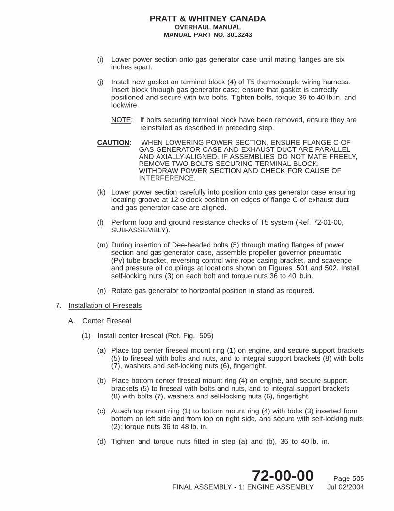
(i) Lower power section onto gas generator case until mating flanges are sixinches apart.
(j) Install new gasket on terminal block (4) of T5 thermocouple wiring harness.Insert block through gas generator case; ensure that gasket is correctlypositioned and secure with two bolts. Tighten bolts, torque 36 to 40 lb.in. andlockwire.
NOTE: If bolts securing terminal block have been removed, ensure they arereinstalled as described in preceding step.
CAUTION: WHEN LOWERING POWER SECTION, ENSURE FLANGE C OFGAS GENERATOR CASE AND EXHAUST DUCT ARE PARALLELAND AXIALLY-ALIGNED. IF ASSEMBLIES DO NOT MATE FREELY,REMOVE TWO BOLTS SECURING TERMINAL BLOCK;WITHDRAW POWER SECTION AND CHECK FOR CAUSE OFINTERFERENCE.
(k) Lower power section carefully into position onto gas generator case ensuringlocating groove at 12 o’clock position on edges of flange C of exhaust ductand gas generator case are aligned.
(l) Perform loop and ground resistance checks of T5 system (Ref. 72-01-00,SUB-ASSEMBLY).
(m) During insertion of Dee-headed bolts (5) through mating flanges of powersection and gas generator case, assemble propeller governor pneumatic(Py) tube bracket, reversing control wire rope casing bracket, and scavengeand pressure oil couplings at locations shown on Figures 501 and 502. Installself-locking nuts (3) on each bolt and torque nuts 36 to 40 lb.in.
(n) Rotate gas generator to horizontal position in stand as required.
7. Installation of Fireseals
A. Center Fireseal
(1) Install center fireseal (Ref. Fig. 505)
(a) Place top center fireseal mount ring (1) on engine, and secure support brackets(5) to fireseal with bolts and nuts, and to integral support brackets (8) with bolts(7), washers and self-locking nuts (6), fingertight.
(b) Place bottom center fireseal mount ring (4) on engine, and secure supportbrackets (5) to fireseal with bolts and nuts, and to integral support brackets(8) with bolts (7), washers and self-locking nuts (6), fingertight.
(c) Attach top mount ring (1) to bottom mount ring (4) with bolts (3) inserted frombottom on left side and from top on right side, and secure with self-locking nuts(2); torque nuts 36 to 48 lb. in.
(d) Tighten and torque nuts fitted in step (a) and (b), 36 to 40 lb. in.
PRATT & WHITNEY CANADAOVERHAUL MANUAL
MANUAL PART NO. 3013243
72-00-00 Page 505FINAL ASSEMBLY - 1: ENGINE ASSEMBLY Jul 02/2004

ENGINE LIFTINGBRACKET
35 36 1
5
VIEW OF FLANGE A(LOOKING FORWARD)
SUPPORT BRACKET REVERSING LINKAGE
SUPPORT BRACKET Py TUBE
2
12
ENGINE LIFTINGBRACKET
SPACERREQUIRED
MOUNTING HOLES FOR OIL−TO−FUELHEATER. WASHER REQUIRED
SPACERREQUIRED
15
14
13
12
11
3837
3628 27
WASHERREQUIRED
10
9
VIEW OF FLANGE C(LOOKING FORWARD)
SCAVENGE OILCOUPLING NO. 31 PRESSURE OIL
COUPLING
VIEW OF FLANGE G(LOOKING FORWARD)
WASHER REQUIRED
8 7
6
❉ ❉
❉
❉
16 1
2
3
4
5
P3 AIR FILTER BRACKET PT6A−28 POST−SB1253OR PT6A−27/28 POST−SB1205 & SB1343
SPACER REQUIRED WHEN POST−SB1205 BRACKET FITTEDP3 AIR FILTER BRACKET PT6A−28 POST−SB1290 & 1378
ELECTRICAL RECEPTACLE BRACKET
LOOP CLAMP SUPPORTING ELECTRICALCABLE (P3 TUBE)
MOUNTING HOLES FOR PROPELLERREVERSING LINKAGE
SPACER REQUIRED POST−SB1290 & 1378BRACKET FITS UNDER SPACER ANDELECTRICAL RECEPTACLE BRACKET
STARTING FLOWCONTROL
NOTEDIAPHRAGM TO HOUSING ATTACHMENT SCREWS
ARE FITTED AT POSITIONS MARKED THUSAND ARE ONLY TO BE LOOSENED TIGHTENED
WHEN DISMANTLING GEARBOX ASSEMBLY
❉14
(PRE−SB) (POST−SB)
C8475C
Bracket Location on Flanges - PT6A-27/-28 Pre-SB1330/Post-SB1343 EnginesFigure 502 (Sheet 1 of 2)
PRATT & WHITNEY CANADAOVERHAUL MANUAL
MANUAL PART NO. 3013243
72-00-00 Page 506FINAL ASSEMBLY - 1: ENGINE ASSEMBLY Jul 02/2004

VIEW OF FLANGE G
❉ ❉❉❉
16 12
3
4
5
6
789
10
11
12
13
1415
MOUNTING HOLES FOR OIL−TO−FUELHEATER. WASHER REQUIRED
ENGINE LIFTINGBRACKET
SPACERREQUIRED
ANGLEBRACKETS
WASHER REQUIRED
P3 FILTER BRACKET
MOUNTING HOLES FOR PROPELLERREVERSING LINKAGE
FUEL PRESSURE TUBEMOUNTING BRACKET
SPACERREQUIRED
SPACERREQUIRED
MOUNTING HOLES FOR OIL−TO−FUELHEATER. WASHER REQUIRED
ANGLEBRACKET
SPACERREQUIRED
SPACERREQUIRED
ENGINE LIFTINGBRACKET
WASHER REQUIREDWASHER REQUIRED
P3 FILTER BRACKET
MOUNTING HOLES FOR PROPELLERREVERSING LINKAGE
VIEW OF FLANGE G
❉❉ ❉
❉
16 12
3
4
5
6
78910
11
13
1415
12
(LOOKING FORWARD)
STARTING FLOWCONTROL
NOTEDIAPHRAGM TO HOUSING ATTACHMENT SCREWSARE FITTED AT POSITIONS MARKED THUS AND
ARE ONLY TO BE LOOSENED OR TIGHTENED WHENDISMANTLING GEARBOX ASSEMBLY.
❉
NOTEDIAPHRAGM TO HOUSING ATTACHMENT SCREWSARE FITTED AT POSITIONS MARKED THUS AND
ARE ONLY TO BE LOOSENED OR TIGHTENED WHENDISMANTLING GEARBOX ASSEMBLY.
❉
(LOOKING FORWARD)
C10252
Bracket Location on Flanges - PT6A-27/-28 Pre-SB1330/Post-SB1343 EnginesFigure 502 (Sheet 2)
PRATT & WHITNEY CANADAOVERHAUL MANUAL
MANUAL PART NO. 3013243
72-00-00 Page 507FINAL ASSEMBLY - 1: ENGINE ASSEMBLY Jul 02/2004

6
14
VIEW A1817
1615
19
1
13
1112
2214
20
21
56
7 89
10
4
3
2
1
23
A
C7483B
Installation of Accessory GearboxFigure 503 (Sheet 1 of 2)
PRATT & WHITNEY CANADAOVERHAUL MANUAL
MANUAL PART NO. 3013243
72-00-00 Page 508FINAL ASSEMBLY - 1: ENGINE ASSEMBLY Jul 02/2004

Key to Figure 503
1. Coupling Shaft2. Preformed Packing3. Washer4. Engine Lifting Bracket5. Self-locking Nut6. Accessory Gearbox Housing7. Preformed Packing8. Plug9. Starter-generator Overboard Drain Adapter (Ref.)
10. Drain Adapter Cap (Ref.)11. Preformed Packing12. Accessory Gearbox Oil Drain Plug13. Adapter (Typical) (Engines with vacuum pump drive), or Tee
(Engines without vacuum pump drive)14. Diaphragm15. Compressor Hub Coupling Shaft16. Preformed Packing17. Oil Tank Center Tube18. Preformed Packing19. Lock Ball20. Preformed Packing21. Oil Transfer Tube22. Compressor Inlet Case23. Spacers24. Screw25. Nut26. Body
PRATT & WHITNEY CANADAOVERHAUL MANUAL
MANUAL PART NO. 3013243
72-00-00 Page 509FINAL ASSEMBLY - 1: ENGINE ASSEMBLY Jul 02/2004

26
25
24
DETAIL A
DETAIL B
B
24
25
26
LOCK−BALL ARRANGEMENT
A
1
15
19
C13622
Installation of Accessory GearboxFigure 503 (Sheet 2)
PRATT & WHITNEY CANADAOVERHAUL MANUAL
MANUAL PART NO. 3013243
72-00-00 Page 510FINAL ASSEMBLY - 1: ENGINE ASSEMBLY Jul 02/2004

(e) Install external lines and components passing through center fireseal mountring.
B. Rear Fireseal and Compressor Wash Ring (if fitted) (Ref. Fig. 505)
(1) The following procedure should be adapted to suit the installation if engine does notincorporate compressor wash ring option.
(a) Remove protective material and air inlet screen from compressor inlet case(Ref. 72-30-00, DISASSEMBLY).
(b) Locate top and bottom rear fireseal sections (16) and (23) around inlet caseand secure together with two bolts (19) and nuts (17), fingertight.
NOTE: On Post-SB1441 engines, install up to four spacers (24) maximumbetween upper and lower fireseal brackets to reduce bracketdistortion.
(c) Align holes in upper support bracket (15) with holes in top half of fireseal andsecure together with bolts (12), washers (14) and nuts (13), fingertight.
NOTE: Support bracket (15), previously installed (Ref. 72-20-00,SUB-ASSEMBLY), is secured at the other end with bolt to breather capflange on compressor inlet case.
(d) Secure lower support bracket (18) to bottom half fireseal (23) with bolts (22)and nuts (21), fingertight.
NOTE: Nuts and bolts securing lower support bracket will be tightened andtorqued during installation of ignition cables at a later stage.
(e) Tighten nuts (13) and (17) and torque 36 to 40 lb.in.
(f) Install air inlet screen and protective material (Ref. 72-30-00, SUB-ASSEMBLY)on compressor inlet case.
C. Installation of Rear Fireseal and Compressor Wash Ring
(1) On engines fitted with compressor wash ring (Ref. IPC), install with rear fireseal asfollows (Ref. Fig. 505):
(a) Remove protective material and air inlet screen from compressor inlet case(Ref. 72-30-00, DISASSEMBLY).
(b) Locate top and bottom rear fireseal sections (16) and (23) around inlet caseand secure together with two bolts (19) and nuts (17), fingertight.
NOTE: On Post-SB1441 engines, install up to four spacers (24) maximumbetween upper and lower fireseal brackets to reduce bracketdistortion.
PRATT & WHITNEY CANADAOVERHAUL MANUAL
MANUAL PART NO. 3013243
72-00-00 Page 511FINAL ASSEMBLY - 1: ENGINE ASSEMBLY Jul 02/2004

7
1
8
CFLANGE
2
3
4
5
6
C7214
Installation of Power Section on Gas Generator CaseFigure 504
PRATT & WHITNEY CANADAOVERHAUL MANUAL
MANUAL PART NO. 3013243
72-00-00 Page 512FINAL ASSEMBLY - 1: ENGINE ASSEMBLY Jul 02/2004

(c) Position compressor wash ring (20), with its bracket holes aligned with holesin top half of fireseal (16) and upper support bracket (15), and secure togetherwith two bolts (12), washers (14) and nuts (13), fingertight.
NOTE: Support bracket (15), previously installed (Ref. 72-20-00SUB-ASSEMBLY), is secured at the other end with bolt to breather capflange on compressor inlet case.
(d) Place compressor wash ring (9), complete with tee (11) and cap (10), oncompressor inlet case, and connect coupling nut of tube (20) to tee.
(e) Correctly align top and bottom fireseal sections (16) and (23) and wash rings(9) and (20); tighten nuts (13) and (17) and torque 36 to 40 lb.in.
(f) Install air inlet screen and protective material (Ref. 72-30-00, SUB-ASSEMBLY)on compressor inlet case.
(g) Tighten tube (20) coupling nut to tee (11), torque 270 to 300 lb.in. and lockwire.
(h) Secure lower support bracket (18) to bottom half fireseal (23) with bolts (22)and nuts (21), fingertight.
NOTE: Nuts and bolts securing lower support bracket will be tightened andtorqued during installation of ignition cables at a later stage.
Key to Figure 504
1. Socket-head Cap Screw2. Sling3. Self-locking Nut4. T5 Thermocouple Wiring Harness and Terminal Block5. D-head Bolts6. Gas Generator Assembly7. Stand8. Exhaust Duct
PRATT & WHITNEY CANADAOVERHAUL MANUAL
MANUAL PART NO. 3013243
72-00-00 Page 513FINAL ASSEMBLY - 1: ENGINE ASSEMBLY Jul 02/2004

1315
14
16
11
12
9
1
2
8
17
24
19
2019
18
17
DETAIL A
A
87
3
2GASGENERATORCASE
5
4
6
23
22
3
IGNITION CABLES
10
C41544
Center and Rear FiresealsFigure 505
PRATT & WHITNEY CANADAOVERHAUL MANUAL
MANUAL PART NO. 3013243
72-00-00 Page 514FINAL ASSEMBLY - 1: ENGINE ASSEMBLY Jul 02/2004

Key to Figure 505
1. Center Fireseal Mount Ring (Top)2. Self-locking Nut3. Bolt4. Center Fireseal Mount Ring (Bottom)5. Support Bracket6. Self-locking Nut and Washer7. Bolt8. Integral Support Bracket9. Compressor Wash Ring (RH Tube) (optional equipment)
10. Cap, Tee11. Tee, Wash Ring12. Bolt13. Self-locking Nut14. Washer15. Upper Support Bracket16. Rear Fireseal Mount Ring (Top)17. Self-locking Nut18. Lower Support Bracket19. Bolt20. Compressor Wash Ring (LH Tube) (optional equipment)21. Self-locking Nut22. Bolt23. Rear Fireseal Mount Ring (Bottom)24. Spacer (Post-SB1441)
PRATT & WHITNEY CANADAOVERHAUL MANUAL
MANUAL PART NO. 3013243
72-00-00 Page 515/516FINAL ASSEMBLY - 1: ENGINE ASSEMBLY Jul 02/2004


FINAL ASSEMBLY - 2: ACCESSORY AND EXTERNAL COMPONENTS
1. General
A. Personnel engaged in the final assembly of the engine should read the Introductionsections of this manual to familiarize themselves with general overhaul procedures(Ref. INTRODUCTION, Outline of Overhaul Procedures).
B. Final assembly is divided into three sections: FINAL ASSEMBLY-1 through FINALASSEMBLY-3.
ENGINE FINAL ASSEMBLY-1: ENGINE ASSEMBLYENGINE FINAL ASSEMBLY-2: ACCESSORY AND EXTERNAL COMPONENTSENGINE FINAL ASSEMBLY-3: FINAL CHECKS
C. The type of lockwire (safety wire) used during assembly shall comply with SpecificationAMS5687 which, unless otherwise specified, is 0.025 inch diameter, heat and corrosionresistant steel wire (PWC05-089) and will not be specified in assembly instructions.
D. Do not allow loop clamps to move cables from their natural contour, when tighteningattachment bolts, as chafing of cable will result.
E. Refer to Final Assembly-1 and Figure 501 for bracket location before finally making anyflange joint.
F. Subassembly instructions for major components are described in the relevantChapter/Section/Unit, as applicable for that component.
G. Where aluminum foil seal retaining plates are installed on external tubes at fireseals, theplates must be installed so that the aluminum foil faces the fireseal mount ring.
H. Ensure that major sub-assemblies, accessories, external components and theirassociated parts are correctly grouped, assembled and installed to suit the engine modeland service bulletin (SB) standard.
2. Consumable Materials
The consumable materials listed below are used in the following procedures.
For alternate products, suppliers, and suppliers addresses, refer to Consumable MaterialsList P/N 3043340.
Item No. Name
PWC03-001 Oil, Engine LubricatingPWC04-001 Grease, SyntheticPWC05-007 Fluid, CheckPWC05-031 Flux, ResinPWC05-089 Lockwire or Safetywire, Nickel Alloy (CRES)PWC05-205 SolderPWC06-005A Lubricant, Fluorocarbon
PRATT & WHITNEY CANADAOVERHAUL MANUAL
MANUAL PART NO. 3013243
72-00-00 Page 501FINAL ASSEMBLY - 2: ACCESSORY AND EXTERNAL COMPONENTS Sep 10/2004

Item No. Name
PWC06-005B Lubricant, FluorocarbonPWC09-005A Compound, Jointing
3. Special Tools
The special tools listed below are used in the following procedures.
Tool No. Name
PWC30114-09 WrenchPWC30114-16 WrenchPWC30800 Stand
4. Fixtures, Equipment and Supplier Tools
Not Applicable
5. Installation of Accessory Units
A. Oil Filter Element, Filter Housing and Check Valve Assembly (Ref. Fig. 501)
(1) With assembly overhauled to Chapter 79-20-02:
(a) Install new preformed packing (12) in groove at inner end of oil filter housing(1).
(b) Install packing retainer (11) (Pre-SB1127), or plastic ring (11) (Post-SB1127),on inner section of groove at center of housing.
(c) Assemble preformed packing (10) SB1127 in outer section of groove, againstpacking retainer or plastic ring (11).
NOTE: When incorporating Post-SB1127, the existing oil filter housing (1),preformed packing (10) and packing retainers (11) are replaced withinnew items of an improved configuration.
(d) Insert oil filter housing and check valve assembly (1) into compressor inlet caseand, using hand pressure, push assembly in until firmly seated.
NOTE: Do not apply side loads on housing while being pressed into inletcase.
(e) Assemble new preformed packings (2) Post-SB1118 and (4) on filter element(3).
(f) Install filter element (3) (perforated flanged end first) into filter housing (1) incompressor inlet case.
PRATT & WHITNEY CANADAOVERHAUL MANUAL
MANUAL PART NO. 3013243
72-00-00 Page 502FINAL ASSEMBLY - 2: ACCESSORY AND EXTERNAL COMPONENTS Sep 10/2004

(g) Install new preformed packing (5) on filter cover (7).
NOTE: Ensure teflon spacer (6) is in position and secure on lugs of filtercover.
(h) Install filter cover on compressor inlet case mounting (13), and secure with fourplain washers (9) and self-locking nuts (8). Tighten nuts and torque 32 to36 lb.in.
B. Starting Control (PT6A-27/-28 Engines) (Ref. Fig. 502)
(1) With starting control overhauled to Chapter 73-10-04:
(a) Remove blanking caps and drain preservation fluid.
NOTE: Depreservation of fuel system is implemented before engine test run(Ref. Testing).
(b) Install starting control (5) on mounting studs on flange G (Ref. Final Assembly-1,Fig. 502). Secure with two washers (4, Fig. 502) and self-locking nuts (3).Tighten nuts and torque 32 to 36 lb.in.
(c) Secure bracket (2) to starting control (5) with bolt (1); torque 32 to 36 lb.in. andlockwire (PWC05-089).
NOTE: At installation of dual scavenge oil tubes, a flexible scavenge hose issecured at its flanged end by two bolts through two remaining holes inbracket (2) into accessory gearbox.
C. Fuel Pump (Ref. Fig. 503)
(1) With fuel pump overhauled to Chapter 73-10-02, install on engine:
NOTE: It may be more convenient to pre-assemble fuel pump to fuel control unit(Ref. Paras. D. and E. following) on the bench, then install units togetheron engine.
(a) Remove protective caps from inlet and outlet ports of pump and drain off anypreservation fluid.
NOTE: Complete depreservation of fuel system is implemented before enginetest run.
(b) Install gasket (4) on mounting pad studs of accessory gearbox (5).
PRATT & WHITNEY CANADAOVERHAUL MANUAL
MANUAL PART NO. 3013243
72-00-00 Page 503FINAL ASSEMBLY - 2: ACCESSORY AND EXTERNAL COMPONENTS Sep 10/2004

VIEW A
VIEW B
VIEW B
12
1
1110
POST−SB1247
PRE−SB1247
12
1
1110
13
13
A
B
12
3
45
6
7
98
C7855
Installation of Oil Filter Element, Housing and Check Valve AssemblyFigure 501
PRATT & WHITNEY CANADAOVERHAUL MANUAL
MANUAL PART NO. 3013243
72-00-00 Page 504FINAL ASSEMBLY - 2: ACCESSORY AND EXTERNAL COMPONENTS Sep 10/2004

CAUTION: PRE-SB1316: DO NOT REMOVE COUPLING FROM PUMP. ENSUREDRIVE COUPLING IS CORRECTLY SECURED ON PUMP INTERNALSPLINES BY LIGHTLY PULLING AND PUSHING BY HAND.COUPLING SHOULD BE SLIGHTLY LOOSE, BUT SHOULD MOVEIN OR OUT. CHECK PROTRUSION OF COUPLING FROMMOUNTING FACE OF PUMP. MEASUREMENT SHOULD BE 1.000TO 1.120 INCHES. ENSURE COUPLING IS NOT DISPLACEDDURING ASSEMBLY TO GEARBOX. POST-SB1316: PUMP INPUTDRIVE COUPLING FEATURES A STOP FLANGE AND MOREPOSITIVE RETENTION. THERE SHOULD BE NO AXIAL MOVEMENT.
CAUTION: FAILURE TO COMPLY WITH STEP (c) FOLLOWING, BYLUBRICATING SPLINES WITH ANYTHING OTHER THAN ENGINEOIL, MAY RESULT IN ACCELERATED SPLINE WEAR AND POSSIBLEFUEL PUMP DECOUPLING.
(c) Remove all traces of grease from splines, and spline bore, and lubricate withclean engine oil (PWC03-001). Ensure oil mist lubrication hole in accessorygearbox fuel control drive gearshaft is not blocked.
CAUTION: TURN ACCESSORY GEARBOX GEAR TRAIN UNTIL SMOOTHENGAGEMENT OF PUMP COUPLING IS ACHIEVED. MISALIGNMENTOR USE OF FORCE MAY CAUSE DISPLACEMENT OF PUMPCOUPLING.
(d) Locate fuel pump (1) on studs of mounting boss (5) turning accessory gearboxgears until coupling shaft splines are aligned, then press pump fully intoengagement. Secure pump with plain washers (3) and self-locking nuts (2).Tighten nuts and torque 75 to 85 lb.in.
(e) Functional check of pump will be conducted at engine testing (Ref. Testing).
Key to Figure 501
1. Oil Filter Housing and Check Valve Assembly2. Preformed Packing3. Filter Element4. Preformed Packing5. Preformed Packing6. Teflon Spacer7. Oil Filter Cover8. Self-Locking Nut9. Washer
10. Preformed Packing11. Packing Retainer (Pre-SB1127)
Fluorocarbon Plastic Ring (Post-SB1127)12. Preformed Packing13. Compressor Inlet Case (Mounting Boss)
PRATT & WHITNEY CANADAOVERHAUL MANUAL
MANUAL PART NO. 3013243
72-00-00 Page 505FINAL ASSEMBLY - 2: ACCESSORY AND EXTERNAL COMPONENTS Sep 10/2004

GFLANGE
5
3 4
1
2
C7479
Installation of Starting ControlFigure 502
PRATT & WHITNEY CANADAOVERHAUL MANUAL
MANUAL PART NO. 3013243
72-00-00 Page 506FINAL ASSEMBLY - 2: ACCESSORY AND EXTERNAL COMPONENTS Sep 10/2004

D. Fuel Control Unit (PT6A-21 Engines) (Ref. Fig. 504)
(1) With fuel control unit overhauled to Chapter 73-20-00:
(a) Remove blanking caps and drain preservation fluid from fuel control unit.
NOTE: Complete depreservation of fuel system is implemented before enginetest run (Ref. Testing).
(b) Install new coupling (5) to fuel control unit.
(c) Install preformed packing (7) in recess on face of fuel pump.
(d) Install fuel control unit (1) on fuel pump and engage with splined coupling (5).Carefully place FCU on studs of pump and secure with washers (3) andself-locking nuts (2). Tighten nuts and torque 75 to 85 lb.in.
(e) Serrated spacer (4), fuel control arm (9) and arm extension (8) remain looselyassembled at this stage. For final adjustment, refer to appropriate procedure ofParagraph 6., following.
E. Fuel Control Unit (PT6A-27/-28 Engines) (Ref. Fig. 505)
(1) With fuel control unit overhauled to Chapter 73-20-00:
(a) Remove blanking caps and drain preservation fluid from fuel control unit.
NOTE: Complete depreservation of fuel system is implemented before enginetest run (Ref. Testing).
(b) Install coupling (4) Post-SB1155, Pre-SB1194 or alternative couplingPost-SB1194 to fuel control unit.
(c) Install preformed packing (5) in recess on face of fuel pump.
(d) Install fuel control unit (1) on fuel pump and engage with splined coupling (4).Carefully place FCU on studs of pump and secure with washers (3) andself-locking nuts (2). Tighten nuts and torque 75 to 85 lb.in.
(e) Serrated spacer (13), fuel control arm (14) and arm extension (15) remainloosely assembled at this stage. For final adjustment, refer to appropriateprocedure of Paragraph 5., following:
Key to Figure 502
1. Bolt2. Mounting Bracket3. Self-locking Nut4. Washer5. Starting Control
PRATT & WHITNEY CANADAOVERHAUL MANUAL
MANUAL PART NO. 3013243
72-00-00 Page 507FINAL ASSEMBLY - 2: ACCESSORY AND EXTERNAL COMPONENTS Sep 10/2004
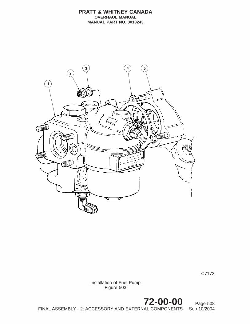
5432
1
C7173
Installation of Fuel PumpFigure 503
PRATT & WHITNEY CANADAOVERHAUL MANUAL
MANUAL PART NO. 3013243
72-00-00 Page 508FINAL ASSEMBLY - 2: ACCESSORY AND EXTERNAL COMPONENTS Sep 10/2004

(f) Locate interconnect rod (10) between arm on fuel control unit and arm on startingcontrol. Temporarily secure upper rod end connector with bolt (6), spacer (7),washer (8) and castellated nut (9), and lower rod end connector with bolt (6),spacers (11) and (12), washer (8) and castellated nut (9).
NOTE: Castellated nuts will be torqued and locked with cotterpins after finaladjustment of interconnect rod.
F. Oil-to-Fuel Heater (Ref. Fig. 506)
(1) With oil-to-fuel heater and oil return check valve overhauled to Chapter 73-10-01:
(a) Remove blanking caps and drain preservation fluid from oil and fuel ports ofoil-to-fuel heater.
NOTE: Complete depreservation of fuel system is conducted before enginetest run (Ref. Testing).
(b) Remove blanking caps from oil return check valve assembly (4), and installpreformed packings (2) and (5) in their respective grooves.
(c) Locate check valve (4) in oil-to-fuel heater port, and insert large end of valvethrough hole in lifting bracket (6) to engage with adapter (1) and studs atflange G.
(d) Secure oil-to-fuel heater to studs with two washers and self-locking nuts; torquenuts 32 to 36 lb.in.
(e) Retain check valve assembly (4) to adapter (1) with retaining plate (3) and twobolts. Torque bolts 32 to 36 lb.in. and lockwire .
G. Check Valve (Minimum Pressurizing) (Ref. Fig. 506)
(1) Install overhauled check valve (minimum pressurizing) to Pre-SB1161 orPost-SB1161 (Ref. Chapter 79-20-03):
(a) Install new preformed packing (19) on spigot of check valve spring seat (18).
(b) Insert check valve (21), valve spring (20) and check valve seat (18) into checkvalve sleeve (22), and secure with retaining ring (17).
(c) Install three new preformed packings (23) on check valve sleeve (22) andinsert into check valve housing (24).
Key to Figure 503
1. Fuel Pump2. Self-locking Nut3. Washer4. Gasket5. Accessory Gearbox Mounting Boss
PRATT & WHITNEY CANADAOVERHAUL MANUAL
MANUAL PART NO. 3013243
72-00-00 Page 509FINAL ASSEMBLY - 2: ACCESSORY AND EXTERNAL COMPONENTS Sep 10/2004

1
2 3 4
8
9
5
6
7
C7203
Installation of Fuel Control UnitFigure 504
PT6A-21 Engines
PRATT & WHITNEY CANADAOVERHAUL MANUAL
MANUAL PART NO. 3013243
72-00-00 Page 510FINAL ASSEMBLY - 2: ACCESSORY AND EXTERNAL COMPONENTS Sep 10/2004

(d) Install new preformed packings (25) and (26) on check valve housing (24),and insert check valve housing into port at 2 o’clock position on compressorinlet case.
(e) Install new preformed packing (16) on adapter (15).
(f) Install adapter (15) and rear fireseal mount ring support bracket (14) on checkvalve housing (24) and secure to compressor inlet case with two bolts. Tightenand torque bolts 36 to 40 lb.in. and lockwire (PWC05-089).
(g) Assemble nut (11), backup ring (12) and new preformed packing (13) on elbow(10).
(h) Install elbow (10) in adapter (15) and position at angle noted on originalinstallation (Ref. INTRODUCTION for elbow assembly procedures).
(i) Install oil tube assembly (9) between elbow on check valve assembly andelbow on oil-to-fuel heater (8). Tighten and torque coupling nuts 90 to100 lb.in.
(j) Torque nut (11) 38 to 42 lb.in. and lockwire (PWC05-089).
H. Propeller Governor (Ref. Fig. 507)
(1) With propeller governor overhauled to Chapter 61-20-00:
(a) Lightly lubricate new preformed packing (2) and install on nipple (3).
(b) Screw nipple (3) into governor Py port and torque 65 to 75 lb.in.
(c) Place new gasket (6) on gearbox mounting pad, raised surface uppermost.
Key to Figure 504
1. Fuel Control Unit2. Self-locking Nuts3. Washer4. Serrated Spacer5. Splined Coupling6. Fuel Pump7. Preformed Packing8. FCU Arm Extension9. Fuel Control Arm (Typical)
PRATT & WHITNEY CANADAOVERHAUL MANUAL
MANUAL PART NO. 3013243
72-00-00 Page 511FINAL ASSEMBLY - 2: ACCESSORY AND EXTERNAL COMPONENTS Sep 10/2004

12
11
89
6
SHAFT EXTENSION FORLOCATION OF SHIPPING PLATE
STARTING FLOW CONTROL
10
10
13 1415
7
8
9
FUEL PUMP
6 1 2 3
4
5
C7478
Installation of Fuel Control UnitFigure 505
PT6A-27/-28 Engines
PRATT & WHITNEY CANADAOVERHAUL MANUAL
MANUAL PART NO. 3013243
72-00-00 Page 512FINAL ASSEMBLY - 2: ACCESSORY AND EXTERNAL COMPONENTS Sep 10/2004

(d) Install governor (1) over studs and engage drive splines. If necessary, rotatepropeller shaft to assist drive engagement. Ensure governor flange is fullyseated on gasket and install washers (5) and nuts (4). Tighten and torque nuts(REF. NO. 186, Table 601) using wrench (Ref. PWC30114-09 orPWC30114-16), as appropriate.
NOTE: Reference should be made to appropriate procedure in Paragraph6.following for pressure tests, connection of linkage and Py tube.
I. Ignition Current Regulator (Ref. Fig. 508)
(1) With regulator overhauled to Chapter 74-10-01, install on engine:
NOTE: The ignition regulator is associated with engines that incorporate the glowplug ignition system.
(a) Locate regulator (1) on three mounting bosses of the accessory gearbox at the8 o’clock position.
(b) Secure regulator with three washers (2) and bolts (3); tighten and torque bolts36 to 40 lb.in. and lockwire (PWC05-089).
J. Ignition Exciter (Ref. Fig. 509)
(1) With ignition exciter overhauled to Chapter 74-10-00, install on engine:
NOTE: The ignition exciter is associated with engines that incorporate the sparkigniter ignition system.
(a) Locate mounting bracket (2) on three mounting bosses of the accessorygearbox at the 8 o’clock position.
Key to Figure 505
1. Fuel Control Unit2. Self-locking Nut3. Washer4. Splined Coupling5. Preformed Packing6. Bolt7. Spacer8. Washer9. Castellated Nut
10. Interconnect Rod11. Spacer12. Spacer13. Serrated Spacer14. Fuel Control Arm15 Fuel Control Arm Extension
PRATT & WHITNEY CANADAOVERHAUL MANUAL
MANUAL PART NO. 3013243
72-00-00 Page 513FINAL ASSEMBLY - 2: ACCESSORY AND EXTERNAL COMPONENTS Sep 10/2004
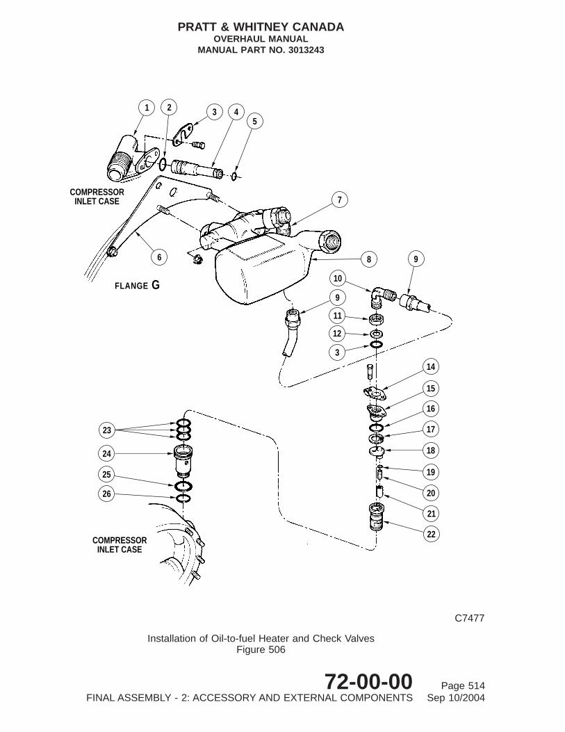
23
24
25
26
COMPRESSORINLET CASE
18
17
16
15
14
19
20
21
22
7
8 9
10
9
11
12
3
COMPRESSORINLET CASE
GFLANGE
6
1 2 45
3
C7477
Installation of Oil-to-fuel Heater and Check ValvesFigure 506
PRATT & WHITNEY CANADAOVERHAUL MANUAL
MANUAL PART NO. 3013243
72-00-00 Page 514FINAL ASSEMBLY - 2: ACCESSORY AND EXTERNAL COMPONENTS Sep 10/2004

(b) Secure bracket with three washers (7) and bolts (6); tighten and torque bolts 36to 40 lb.in. and lockwire (PWC05-089).
(c) Install vibration absorber mounts (10) Post-SB1422 in holes in bracket (2) andinsert sleeves (11) into mounts.
(d) Install ignition exciter (3) on mounting bracket (2).
NOTE: Mounting bracket (2) Post-SB1337 on PT6A-21/28 engines (BeechInstallation) has repositioned ignition exciter mounting holes (Ref. Fig.509).
(e) Secure exciter with four bolts (1), washers (4) and self-locking nuts (5)Pre-SB1422; torque nuts 36 to 40 lb.in. Alternatively, secure exciter with bolts(12), washers (9) and nuts (8) Post-SB1422; torque nuts 36 to 40 lb.in.
Key to Figure 506
1. Oil Return Adapter2. Preformed Packing3. Retaining Plate4. Oil Return Check Valve Assembly5. Preformed Packing6. Engine Lifting Bracket (Rear)7. Elbow8. Oil-to-fuel Heater9. Oil Tube Assembly
10. Elbow11. Nut12. Back-up Ring13. Preformed Packing14. Rear Fireseal Mount Ring
Ring Support Bracket15. Adapter16. Preformed Packing17. Retaining Ring18. Retaining Plate Spring Seat (Pre-SB1161)18. Check Valve Spring Seat (Post-SB1161)19. Preformed Packing20. Valve Spring21. Check Valve (Minimum Pressurizing)22. Check Valve Sleeve23. Preformed Packings24. Check Valve Housing25. Preformed Packing26. Preformed Packing
PRATT & WHITNEY CANADAOVERHAUL MANUAL
MANUAL PART NO. 3013243
72-00-00 Page 515FINAL ASSEMBLY - 2: ACCESSORY AND EXTERNAL COMPONENTS Sep 10/2004

12
3
4
5
6
7
C7199
Installation of Propeller GovernorFigure 507
PRATT & WHITNEY CANADAOVERHAUL MANUAL
MANUAL PART NO. 3013243
72-00-00 Page 516FINAL ASSEMBLY - 2: ACCESSORY AND EXTERNAL COMPONENTS Sep 10/2004

6. Installation of Externals
A. Fuel Delivery Tubes and Flexible Hoses (PT6A-21 Engines) (Ref. Fig. 510)
(1) Secure coupling nuts of flexible hose (1) to straight nipple on fuel pump and elbowon FCU. Torque coupling nuts 170 to 200 lb.in. and lockwire.
NOTE: Make sure hose fits snugly between FCU and fuel pump fittings withoutforcing or twisting.
(2) Secure coupling nuts of flexible hose (2) to elbow on fuel pump and straight nippleon oil-to-fuel heater. Tighten coupling nuts, torque 450 to 500 lb.in., and lockwire.
(3) Insert coupling (6) into bracket (5) of flange G. Secure coupling with jam nut (4)and torque nut 38 to 42 lb.in.
(4) Slide tube seals (17) over fuel pressure tube (20) on each side of centre firesealmount ring. Butt seals against mount ring. Position insulations (16) next to sealsand retaining plates (15) next to insulations.
(5) Slide tube seals (9) over fuel pressure tube (20) on each side of rear fireseal mountring. Butt seals against mount ring. Position insulations (8) next to seals andretaining plates (7) next to insulations.
CAUTION: HEAD OF BOLTS SECURING RETAINING PLATES TO REAR ANDCENTER FIRESEAL MUST BE LOCATED ON AIR INLET SIDE.
(6) Secure tube seals, insulations and retaining plates to center fireseal mount ring withbolts (18) and nuts (19). Secure tube seals, insulations and retaining plates to rearfireseal mount ring with bolts (10) and nuts (11). Torque nuts to obtain firmcontact of parts plus 180 degrees.
(7) Secure loop clamps (12 and 23) to fuel pressure tube (20).
(8) Secure loop clamp (12) to support bracket (22) to rear of fuel drain valve on gasgenerator case with washer(s) (21), nut (13) and bolt (14). Tighten nut and torque36 to 40 lb.in.
NOTE: To align front fuel tube, a maximum of two spacing washers may bepositioned between loop clamps and support bracket.
Key to Figure 507
1. Propeller Governor (Typical)2. Preformed Packing3. Straight nipple4. Self-locking Nut5. Washer6. Gasket7. Reduction Gearbox
PRATT & WHITNEY CANADAOVERHAUL MANUAL
MANUAL PART NO. 3013243
72-00-00 Page 517FINAL ASSEMBLY - 2: ACCESSORY AND EXTERNAL COMPONENTS Sep 10/2004

1
23
32
ACCESSORY GEARBOX
C7481
Installation of Ignition Current RegulatorFigure 508
PRATT & WHITNEY CANADAOVERHAUL MANUAL
MANUAL PART NO. 3013243
72-00-00 Page 518FINAL ASSEMBLY - 2: ACCESSORY AND EXTERNAL COMPONENTS Sep 10/2004

(9) Secure coupling nuts of tube (20) to bulkhead coupling (6) and elbow on flow dividerand dump valve. Torque coupling nuts 90 to 100 lb.in., and lockwire.
(10) For Pre-SB1471 Engines: Connect rear fuel pressure tube (3) between bulkheadcoupling (6) and connector on fuel control unit. Tighten tube coupling nut, torque270 to 300 lb.in. and lockwire.
(11) For Post-SB1471 Engines:
(a) Remove existing bolt and use to secure bracket (29) to boss of reductiongearbox housing assembly.
(b) Secure loop clamp (28) to tube assembly (3) and install to bracket (29) with nut(26) and bolt (27). Torque nut 36. to 40 lb.in.
(c) Install tube assembly (24) or fuel flowmeter (25) if fitted, to rear fuel pressuretube (3) and tube assembly (30). Torque coupling nuts 90 to 100 lb.in. andlockwire.
(d) Install tube assembly (30) to bulkhead coupling (6). Torque coupling nut 90 to100 lb.in. and lockwire.
(e) Connect rear fuel pressure tube (3) to connector on fuel control unit. Tightenand torque coupling nut 270 to 300 lb.in. and lockwire.
(12) Check for leaks during engine testing (Ref. Testing).
B. Fuel Delivery Tubes and Flexible Hoses (PT6A-27/-28 Engines) (Ref. Fig. 511)
(1) Connect flexible hose (6) to straight nipple (7) and FCU elbow (5); tighten and torquecoupling nuts 170 to 200 lb.in. and lockwire.
(2) Connect flexible hose (9) to straight nipple (8) and elbow (10) on fuel pump; tightenand torque coupling nuts 450 to 500 lb.in. and lockwire.
NOTE: Flexible hose (9) is not used on some installed PT6A-28 engine models.Component is airframe supplied. Slave hose must be provided for enginetest.
(3) Connect fuel bypass tube (3) between connector (1) on fuel control unit and tee(11) on starting control. Torque coupling nuts 90 to 100 lb.in. and lockwire.
Key to Figure 508
1. Ignition Regulator2. Washer3. Bolt
PRATT & WHITNEY CANADAOVERHAUL MANUAL
MANUAL PART NO. 3013243
72-00-00 Page 519FINAL ASSEMBLY - 2: ACCESSORY AND EXTERNAL COMPONENTS Sep 10/2004

7 6
89
1011
9
12
7 6
3
3
4 5
POST−SB1422
2ACCESSORY GEARBOX
POST−SB1337ACCESSORY GEARBOX
21
ACCESSORY GEARBOX
7 6
3
4 5
2
1
PRE−SB1337PRE−SB1422
C8496B
Installation of Ignition ExciterFigure 509
PRATT & WHITNEY CANADAOVERHAUL MANUAL
MANUAL PART NO. 3013243
72-00-00 Page 520FINAL ASSEMBLY - 2: ACCESSORY AND EXTERNAL COMPONENTS Sep 10/2004

CAUTION: WHEN INSTALLING FUEL TUBE (4) ENSURE THAT SHORTER END ISCONNECTED TO FUEL CONTROL UNIT. INCORRECT INSTALLATIONMAY RESULT IN CHAFING BETWEEN TUBE AND ADJACENT AIRFRAMEEQUIPMENT.
(4) Connect fuel pressure tube (4) between adapter (2) on fuel control unit and elbow(14) on starting control. Torque coupling nuts 90 to 100 lb.in., and lockwire.
(5) Place one (rear) seal retaining plate (15) over rear coupling nut on fuel pressuretube (20), insert tube forward through rear fireseal mount ring and place twocenter seal retaining plates (15) over tube.
(6) Insert tube (20) forward through center fireseal mount ring, and place one (forward)seal retaining plate (15) over tube.
(7) Secure coupling nuts of tube (20) to elbow (22) and straight nipple (12). Torquecoupling nuts 90 to 100 lb.in. and lockwire .
(8) Place one (rear) seal retaining plate (15) over rear of fuel pressure tube (21), inserttube forward through rear fireseal and place two (center) seal retaining plates (15)over tube.
(9) Insert tube (21) forward through center fireseal, and place one (forward) sealretaining plate (15) over tube.
(10) Secure coupling nuts of tube (21) to elbow (23) on fuel manifold inlet adapterassembly and straight nipple (13) on starting control. Torque coupling nuts 90 to100 lb.in. and lockwire .
(11) Place insulations (16) and seals (17), with slits diametrically opposite, on tubes (20)and (21) at each side of center and rear fireseal. Position retaining plates (15)(already on tubes) next to insulation (16), with aluminized side of insulation facingmount rings (eight locations).
Key to Figure 509
1. Bolt (Pre-SB1422)2. Mounting Bracket3. Ignition Exciter4. Washer (Pre-SB1422)5. Nut (Pre-SB1422)6. Bolt7. Washer8. Nut (Post-SB1422)9. Washer (Post-SB1422)
10. Vibration Absorber Mount (Post-SB1422)11. Flanged Sleeve (Post-SB1422)12. Bolt (Post-SB1422)
PRATT & WHITNEY CANADAOVERHAUL MANUAL
MANUAL PART NO. 3013243
72-00-00 Page 521FINAL ASSEMBLY - 2: ACCESSORY AND EXTERNAL COMPONENTS Sep 10/2004

18
1615
1716
1519
CENTER FIRESEALMOUNT RING
20
FLOW DIVIDER ANDDUMP VALVE
1
45
6
PRE−SB1471
B
10 7
8
12
11
7
89
REAR FIRESEALMOUNT RING
20 1214
22
21
23
13
B
AFUELCONTROLUNIT
OIL−TO−FUEL HEATER
FUELPUMP
2
POST−SB1471
3
26
28
2927
24
30
3
25
VIEW A
VIEW
C7922C
Installation of Fuel Delivery Tubes and Flexible HosesFigure 510
PT6A-21 Engines
PRATT & WHITNEY CANADAOVERHAUL MANUAL
MANUAL PART NO. 3013243
72-00-00 Page 522FINAL ASSEMBLY - 2: ACCESSORY AND EXTERNAL COMPONENTS Sep 10/2004

CAUTION: HEADS OF BOLTS SECURING SEAL RETAINING PLATES TO REARAND CENTER FIRESEALS MUST BE LOCATED ON AIR INLET SIDE.
(12) Secure plates (15), insulation (16) and seals (17) to center and rear fireseal mountrings with two bolts and self-locking nuts. Tighten nuts and torque (REF. NO. 549,Table 601).
Key to Figure 510
1. Fuel Hose (Fuel Pump to FCU)2. Fuel Hose (Fuel Heater to Fuel Pump)3. Fuel Tube (rear)4. Jam Nut5. Bracket6. Coupling7. Retaining Plate8. Insulation9. Seal
10. Bolt11. Self-locking Nut12. Loop Clamp13. Self-locking Nut14. Bolt15 Retaining Plate16. Insulation17. Seal18. Bolt19. Self-locking Nut20. Fuel Tube (front)21. Spacing Washer(s) (two max)22. Support Bracket23. Loop Clamp (glow plug ignition only)24. Tube Assembly (Post-SB1471)25. Fuel Flowmeter (Airframe Supplied) (Post-SB1471)26. Nut (Post-SB1471)27. Bolt (Post-SB1471)28. Loop Clamp (Post-SB1471)29. Bracket (Post-SB1471)30. Tube Assembly (Post-SB1471)
PRATT & WHITNEY CANADAOVERHAUL MANUAL
MANUAL PART NO. 3013243
72-00-00 Page 523FINAL ASSEMBLY - 2: ACCESSORY AND EXTERNAL COMPONENTS Sep 10/2004

(13) Install loop clamps (18) and (19) on their respective fuel pressure tube (20) and(21). Locate spacing washers (if required for alignment) between clamps andsecure with two nuts and bolts to support bracket attached to rear drain valve ongas generator case. Tighten nuts and torque 36 to 40 lb.in.
NOTE: To align fuel pressure tubes, a maximum of two spacing washers can beused between each loop clamp and the support bracket.
(14) Install one loop clamp (24) on each tube (20) and (21) and, on engines with glowplug ignition system, install one additional loop clamp (26) on each tube.
NOTE: Loop clamps will be secured during subsequent installation of ignitionleads.
(15) Check lines for leaks during engine test (Ref. Testing).
C. Pressure Oil Transfer Tubes (Ref. Fig. 512)
(1) Install pressure oil transfer tube:
(a) Install preformed packings (14) on both ends of front transfer tube (15), andpreformed packing (17) in groove of elbow (16).
(b) Place elbow (16) on one end of tube (15) and insert other end into externalcoupling (13) on flange C.
NOTE: External coupling was installed after assembly of power section to gasgenerator assembly.
(c) Position elbow (16) on reduction gearbox and secure with two bolts andwashers; torque bolts 36 to 40 lb.in. and safety wire.
(d) Install preformed packing (12) on forward end of center transfer tube (11), andinsert tube into coupling (13).
(e) Place one (center) seal retaining plate assembly (5) and seal (4) over rear ofrear transfer tube (6), and slide toward center of tube.
NOTE: On later configuration, install insulation between plates (5) and seals(4) (Ref. IPC).
(f) Place one (center) seal retaining plate assembly (10) and seal (9) over forwardend of transfer tube (6), and slide toward center of tube.
NOTE: On later configuration, install insulation between plates (10) and seals(9) (Ref. IPC).
(g) Install preformed packings (3) on each end of transfer tube (6) and preformedpacking (7) on adapter.
NOTE: Alignment spacers (8) are used on adapter of rear tube (Pre-SB1169only).
PRATT & WHITNEY CANADAOVERHAUL MANUAL
MANUAL PART NO. 3013243
72-00-00 Page 524FINAL ASSEMBLY - 2: ACCESSORY AND EXTERNAL COMPONENTS Sep 10/2004

(h) Insert rear end of transfer tube (6) through rear fireseal mount ring and forwardend of tube through center fireseal mount ring.
(i) Place one (forward) seal (9), insulation (19) and seal retaining plate assembly(10) over forward end of tube (6).
NOTE: On later configuration, install insulation between plates (10) and seals(9) (Ref. IPC).
(j) Place one (rear) seal (4), insulation (18) and seal retaining plate assembly (5)over rear end of tube (6).
NOTE: 1. On later configuration, install insulation between plates (5) and seals(4) (Ref. IPC).
NOTE: 2. Aluminized side of retaining plate assemblies to be facing mountrings (four locations).
(k) Install preformed packing (2) on elbow (1), and place elbow on rear end oftransfer tube (6).
(l) Insert forward end of transfer tube (6) into rear end of transfer tube (11),adapter into boss on gas generator case, and locate elbow (1) on inlet case.
(m) Install elbow (1) with bolts and washers. Torque bolts 36 to 40 lb.in. and safetywire.
(n) Secure flange of adapter to gas generator case with two bolts. Tighten, torquebolts 36 to 40 lb.in. and lockwire.
CAUTION: HEADS OF BOLTS SECURING SEAL RETAINING PLATEASSEMBLIES TO REAR AND CENTER FIRESEALS ARE LOCATEDON COMPRESSOR AIR INLET SIDE OF RESPECTIVEFIRESEALS.
(o) Secure seal retaining plate assemblies (5) and (10) and seals (4) and (9) tocenter and rear fireseals with two bolts and self-locking nuts at each location.Tighten nuts and torque (REF. NO. 549, Table 601).
(p) Check for oil leaks during engine test (Ref. Testing).
D. No. 2 Bearing Scavenge Oil Tube (Ref. Fig. 513)
(1) Install preformed packings (1) and (9) on front and rear flanges (3) and (10) ofNo. 2 bearing scavenge tube (11). Install gasket (2) on front flange.
(2) Pass front end of scavenge tube through rear fireseal mount ring, and locateflanges on respective bosses on gas generator and compressor inlet cases.
(3) Locate rear fireseal mount ring support bracket (8) (already installed on fireseal) onfront hole of scavenge tube rear flange (10). Secure tube rear flange (10) andbracket to boss with two bolts. Tighten bolts, torque 36 to 40 lb.in. and lockwire.
PRATT & WHITNEY CANADAOVERHAUL MANUAL
MANUAL PART NO. 3013243
72-00-00 Page 525FINAL ASSEMBLY - 2: ACCESSORY AND EXTERNAL COMPONENTS Sep 10/2004

1
3
4
25
8
7FCU
OIL−TO−FUEL HEATER
FUEL PUMP 910
1113
FUELPUMP
1716 15
14 STARTING CONTROL
12
FUEL MANIFOLDINLET ADAPTER
ASSEMBLY
23
21
22
1516
17
CENTER FIRESEALREAR FIRESEALMOUNT RINGS
19
18
25
PT6A−27/28 ENGINES (POST−SB1196)
24
DETAIL A
VIEW B
B
26
20
21
2619R/H IGNITION CABLE
L/H IGNITION CABLE
A
A
A
A
18
20
19
25
1824
PT6A−27/28 ENGINES(PRE−SB1196)
TYP. 4 PLACESTUBE SEALING
C8486
Installation of Fuel Delivery Tubes and Flexible HosesFigure 511
PT6A-21/-28 Engines
PRATT & WHITNEY CANADAOVERHAUL MANUAL
MANUAL PART NO. 3013243
72-00-00 Page 526FINAL ASSEMBLY - 2: ACCESSORY AND EXTERNAL COMPONENTS Sep 10/2004

(4) Secure front flange (3) to gas generator case with two bolts. Tighten bolts, torque 36to 40 lb.in. and lockwire.
(5) Install seals (6) and seal retaining plate assemblies (5) and (7) (foil side facingseal) on scavenge tube. Secure assemblies and seals to rear fireseal mount ringwith two retaining plates (4), four bolts (heads located on compressor air inlet side ofmount ring) and self-locking nuts. Tighten nuts and torque (REF. NO. 549, Table601).
(6) Check for oil leaks (Ref. Testing).
Key to Figure 511
1. Connector (on FCU)2. Adapter (on FCU)3. Fuel Bypass Tube4. Fuel Pressure Tube5. Elbow (on FCU)6. Fuel Hose7. Straight Nipple8. Straight Nipple9. Fuel Hose
10. Elbow (on Fuel Pump)11. Tee12. Straight Nipple13. Straight Nipple14. Elbow15. Seal Retaining Plate16. Insulation17. Seal18. Loop Clamp19. Loop Clamp20. Fuel Pressure Tube - Secondary21. Fuel Pressure Tube - Primary22. Elbow23. Elbow24. Loop Clamps25. Backplate26. Loop Clamps (Glow Plug Ignition)
PRATT & WHITNEY CANADAOVERHAUL MANUAL
MANUAL PART NO. 3013243
72-00-00 Page 527FINAL ASSEMBLY - 2: ACCESSORY AND EXTERNAL COMPONENTS Sep 10/2004
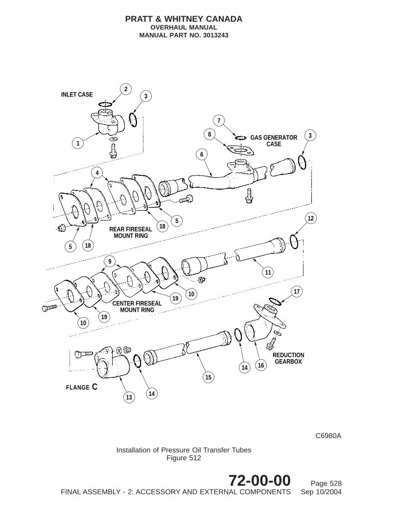
CFLANGE
13 14
15
10
14 16
17
REDUCTIONGEARBOX
12
11
19
1019
9
CENTER FIRESEALMOUNT RING
REAR FIRESEALMOUNT RING
5 18
518
4
1
23INLET CASE
3
7
8
6
GAS GENERATORCASE
C6980A
Installation of Pressure Oil Transfer TubesFigure 512
PRATT & WHITNEY CANADAOVERHAUL MANUAL
MANUAL PART NO. 3013243
72-00-00 Page 528FINAL ASSEMBLY - 2: ACCESSORY AND EXTERNAL COMPONENTS Sep 10/2004

E. External Dual Scavenge Oil Tubes (Ref. Fig. 514)
(1) If the intent of SB1087 is embodied, ensure that seal retaining plates (11 and 13),inner seals (12) and (14) and rear transfer tubes (10) are of the correct partnumbers, as these parts to Pre-SB1087and Post-SB1087 standard are notinterchangeable. Center and rear fireseal lower mounting rings are also modified toaccommodate this service bulletin.
(a) Install preformed packings (9) on each end of rear transfer tubes (10).
(b) Place inner seals (12) and (14) and inner retaining plates (11) and (13) in thecenter of both rear transfer tubes (10).
(c) Insert transfer tubes (10) through center and rear fireseals, and locate outerseals (12) and (14) and outer retaining plates (11) and (13) over ends oftubes.
(d) Remove transfer coupling (8), installed during initial assembly, from flange C.
(e) Connect rear ends of transfer tubes (10) to ports of external scavenge pump.
(f) Assemble transfer coupling (8) over ends of tubes (10); mount coupling on flangeC, engaging dowel of coupling in flange hole.
Key to Figure 512
1. Elbow (Rear)2. Preformed Packing3. Preformed Packing4. Seals5. Retaining Plates6. Rear Tube Post-SB1169
Rear Tube Pre-SB11697. Preformed Packing8. Alignment Spacers (Pre-SB1169 only, ref)9. Seals
10. Retaining Plates11. Center Tube Post-SB1169
Center Tube Pre-SB116912. Preformed Packing13. Coupling14. Preformed Packing15. Front Tube16. Elbow (Front)17. Preformed Packing18. Insulation Plate19. Insulation Plate
PRATT & WHITNEY CANADAOVERHAUL MANUAL
MANUAL PART NO. 3013243
72-00-00 Page 529FINAL ASSEMBLY - 2: ACCESSORY AND EXTERNAL COMPONENTS Sep 10/2004

1
2
3
45
6
REAR FIRESEALMOUNT RING
67
89 10
11
4
C7463
Installation of No. 2 Bearing Scavenge Oil TubeFigure 513
PRATT & WHITNEY CANADAOVERHAUL MANUAL
MANUAL PART NO. 3013243
72-00-00 Page 530FINAL ASSEMBLY - 2: ACCESSORY AND EXTERNAL COMPONENTS Sep 10/2004

(g) Loosely secure coupling with three Dee-headed bolts, washers andself-locking nuts.
(h) Install preformed packings (1) on short transfer tube (2) and insert tube intoboss on reduction gearbox.
(i) Assemble sleeve seal (4) and preformed packing (3) in No. 3 and 4 bearingscavenge port of front transfer elbow (5).
(j) Install preformed packings (6) on both ends of front transfer tubes (7). Inserttubes into respective ports on transfer elbow (5).
(k) Place oil transfer elbow (5) and tubes under reduction gearbox. Insert shorttransfer tube (2) into port on transfer elbow (5), and rear end of transfertubes (7) into respective ports on transfer coupling (8).
(l) Locate oil transfer elbow on mounting boss of reduction gearbox, making surethat preformed packing (3) and sleeve seal (4) mate with corresponding hole inboss. Secure elbow (5) with three bolts and plain washers. Tighten bolts,torque 36 to 40 lb.in. and lockwire.
(m) Torque self-locking nuts, that secure oil transfer coupling (8) to flange C, 36 to40 lb.in.
(n) Tighten self-locking nuts and torque (REF. NO. 549, Table 601).
(o) Install preformed packing (16) on flanged end of scavenge oil hose (15), andinsert into boss on accessory gearbox. Align bolt holes on flange withcorresponding holes in accessory gearbox and bracket (17) on starting control(PT6A-27/-28 engines) and secure with two bolts. Torque bolts 36 to 40 lb.in.and lockwire.
NOTE: Scavenge oil hose (15) Pre-SB1116 is fitted to engines withoutvacuum pump drive; scavenge oil hose (15) Post-SB1116 is fitted toengines with vacuum pump drive.
Key to Figure 513
1. Preformed Packing2. Gasket3. Front Flange4. Seal Retaining Plate5. Seal Retaining Plate Assembly6. Seal7. Seal Retaining Plate Assembly8. Rear Fireseal Mount Ring Support Bracket9. Preformed Packing
10. Rear Flange11. No. 2 Bearing Scavenge Tube
PRATT & WHITNEY CANADAOVERHAUL MANUAL
MANUAL PART NO. 3013243
72-00-00 Page 531FINAL ASSEMBLY - 2: ACCESSORY AND EXTERNAL COMPONENTS Sep 10/2004

(p) Secure coupling nut of hose (15) to adapter or tee, as applicable, on scavengepump housing. Tighten coupling nut, torque 400 to 500 lb.in. and lockwire.
F. Ignition Cables (PT6A-21 Engines) (Ref. Figs. 515 and 516)
(1) Install glow plug ignition cables Pre-SB1196 (Ref. Fig. 515):
(a) Insert both ignition cables (3) through rear fireseal (13) and center fireseal (14)apertures.
(b) Position flanges (8) of each cable on rear and center fireseal (13) and (14) andsecure with four bolts and self-locking nuts. Two top bolts also secure mountring support bracket (7). Tighten nuts and torque 36 to 40 lb.in.
NOTE: Heads of bolts securing flanges to center and rear fireseal mountrings must be located on compressor air inlet side of respective mountring.
CAUTION: UNDER NO CIRCUMSTANCES ARE LUBRICANTS OF ANY TYPETO BE USED ON CABLES WITH TEFLON INSULATED SLEEVES.LUBRICANTS CONTAINING GREASE, SILICONE OR PETROLATUMMUST NOT BE USED ON ANY IGNITION COMPONENTS ASCONTAMINATION OF ELECTRICAL CONTACTS WITHINCONNECTORS OR CENTRAL CONDUCTOR OF CABLE CANRESULT IN A HIGH RESISTANCE PATH WHICH COULD GENERATEHEAT AND OXIDATION.
(c) Lightly spray insulated ends of cable conductors with fluorocarbon dry-spraylubricant (PWC06-005A).
CAUTION: DO NOT ALLOW BRAIDING, FERRULES OR GLOW PLUG TOTURN WHEN SCREWING ON COUPLING NUTS.
(d) Connect coupling nuts on ignition cables (3) to respective glow plugs, andconnectors on ignition regulator. Screw couplings onto mating thread byhand, making sure no binding occurs between coupling nuts and cable.
(e) Tighten and torque coupling nut connectors to glow plugs (REF. NO. 566, Table601) and ignition regulator (REF. NO. 561, Table 601). Lockwire coupling nut atignition regulator end.
(f) Assemble one loop clamp (4) on each cable (3) (Ref. Details A and B); secureto bracket (2) on center fireseal (14) and integral bracket on gas generatorcase with bolts and self-locking nuts. Tighten nuts and torque 36 to 40 lb.in.
(g) Assemble four loop clamps (9) on ignition cable (3) (Ref. Detail C).
(h) Secure two of these loop clamps to loop clamps (10) on fuel tube with boltsand self-locking nuts.
(i) Secure third loop clamp to bracket (12) on air inlet screen with bolt andself-locking nut.
PRATT & WHITNEY CANADAOVERHAUL MANUAL
MANUAL PART NO. 3013243
72-00-00 Page 532FINAL ASSEMBLY - 2: ACCESSORY AND EXTERNAL COMPONENTS Sep 10/2004

(j) Secure fourth loop clamp to fuel line and ignition support bracket (11) with boltand self-locking nut.
(k) Tighten all self-locking nuts and torque 36 to 40 lb.in.
(l) Assemble four loop clamps (6) on ignition cable (3) (Ref. Detail D), and securein pairs to brackets (5) on flange E with bolts and self-locking nuts. Tightennuts and torque 36 to 40 lb.in.
(2) Install spark ignition cables (Post-SB1196) (Ref. Fig. 516):
(a) Insert both ignition cables (6) through rear fireseal (14) and center fireseal (4)apertures.
NOTE: Heads of bolts securing cable flanges to fireseals to be located on airinlet side of respective mount ring.
(b) Position flanges of each cable (6) (Ref. Detail A) on center fireseal (4) withbrackets (3) located on rear face of upper hole. Secure together at eachcable flange position with two bolts and self-locking nuts. Tighten nuts and torque36 to 40 lb.in.
(c) Position flanges of each cable (6) on front of rear fireseal (14) (Pre-SB1482,Ref. Detail D) or rear of rear fireseal (14) (Post-SB1482, Ref. Detail F) withbrackets (11) and (15) positioned over one hole in cable flange. Secure togetherat each cable flange location with two bolts and self-locking nuts. Tightennuts and torque 36 to 40 lb.in.
CAUTION: UNDER NO CIRCUMSTANCES ARE LUBRICANTS OF ANY TYPETO BE USED ON CABLES WITH TEFLON INSULATED SLEEVES.LUBRICANTS CONTAINING GREASE, SILICONE OR PETROLATUMMUST NOT BE USED ON ANY IGNITION COMPONENTS ASCONTAMINATION OF ELECTRICAL CONTACTS WITHINCONNECTORS OR CENTRAL CONDUCTOR OF CABLE CANRESULT IN A HIGH RESISTANCE PATH WHICH COULD GENERATEHEAT AND OXIDATION.
(d) Taking care not to spray electrical contacts, lightly spray insulated ends ofcable conductors with fluorocarbon dry-spray lubricant (PWC06-005A).
CAUTION: DO NOT ALLOW BRAIDING, FERRULES OR IGNITER PLUG TOTURN WHEN SCREWING ON COUPLING NUTS.
(e) Connect coupling nuts at ends of ignition cables (6) to respective spark ignitersand connectors on ignition exciter. Screw couplings onto mating threads byhand, making sure that no binding occurs between coupling nut and cable.Tighten and torque cable coupling nuts (REF. NO. 566, Table 601). Securecoupling nuts at ignition exciter end with lockwire.
(f) Attach bracket (2) (Ref. Detail A) to angle bracket on center fireseal (4) (twoplaces) with bolts and self-locking nuts. Tighten nuts and torque 36 to 40 lb.in.
PRATT & WHITNEY CANADAOVERHAUL MANUAL
MANUAL PART NO. 3013243
72-00-00 Page 533FINAL ASSEMBLY - 2: ACCESSORY AND EXTERNAL COMPONENTS Sep 10/2004

7
68
B
5
43
2
6
1
A
914
11
9
10
13
CENTER FIRESEALMOUNT RING
REAR FIRESEALMOUNT RING
15
1617
C
CBA
12
C7464
Installation of External Dual Scavenge Oil TubesFigure 514
PRATT & WHITNEY CANADAOVERHAUL MANUAL
MANUAL PART NO. 3013243
72-00-00 Page 534FINAL ASSEMBLY - 2: ACCESSORY AND EXTERNAL COMPONENTS Sep 10/2004

(g) Assemble loop clamps (1) and (5) on both ignition cables (Ref. Detail A) andsecure to angle brackets (2) and (3) (already installed) with bolts andself-locking nuts. Tighten nuts and torque 36 to 40 lb.in.
CAUTION: LOOP CLAMPS MUST BE POSITIONED TO REDUCE POSSIBLECHAFING OF THE IGNITION CABLE WITH THE FUEL LINE IN THEVICINITY OF CENTER FIRESEAL AND AIR SCREEN.
(h) Assemble loop clamp (16) on ignition cable (6). Secure loop clamp to rear fuelpressure tube (20) with bolts and self-locking nuts. Tighten nuts and torque 36to 40 lb.in.
1 Pre-SB1482; Assemble loop clamp (9) on ignition cable (6). Secure clampto bracket (22) on air inlet screen. Tighten nuts and torque 36 to 40 lb.in.(Ref. Detail D).
2 Post-SB1482; Assemble loop clamp (9) on ignition cable (6). Secure clampto bracket (22) with bolt and self locking nut, and bracket (22) to bracket(21) using bolt, washer and self-locking nut. Tighten nuts and torque 36 to40 lb.in. (Ref. Detail E).
(i) Assemble loop clamps (10) and (13) on ignition cables (6) (Ref. Detail D or F)and secure to brackets (11) and (15) (already installed) with bolts andself-locking nuts. Tighten nuts and torque 36 to 40 lb.in.
Key to Figure 514
1. Preformed Packings2. Transfer Tube3. Preformed Packing4. Sleeve Seal5. Front Scavenge Oil Transfer Tube6. Preformed Packing7. Front Transfer Tubes8. External Scavenge Oil Transfer Coupling9. Preformed Packings
10. Rear Transfer Tubes11. Seal Retaining Plates12. Seals13. Seal Retaining Plates14. Seals15. Scavenge Oil Hose16. Preformed Packing17. Support Bracket (Starting Flow Control, PT6A-27/-28
Engines)
PRATT & WHITNEY CANADAOVERHAUL MANUAL
MANUAL PART NO. 3013243
72-00-00 Page 535FINAL ASSEMBLY - 2: ACCESSORY AND EXTERNAL COMPONENTS Sep 10/2004
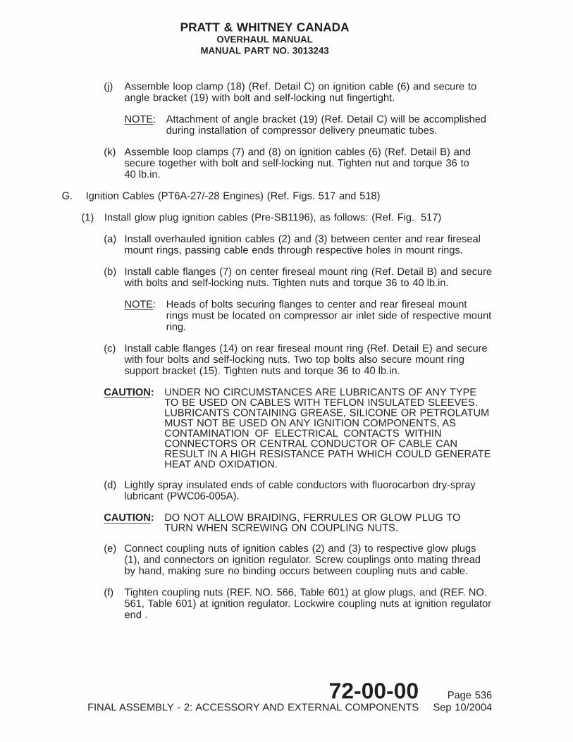
(j) Assemble loop clamp (18) (Ref. Detail C) on ignition cable (6) and secure toangle bracket (19) with bolt and self-locking nut fingertight.
NOTE: Attachment of angle bracket (19) (Ref. Detail C) will be accomplishedduring installation of compressor delivery pneumatic tubes.
(k) Assemble loop clamps (7) and (8) on ignition cables (6) (Ref. Detail B) andsecure together with bolt and self-locking nut. Tighten nut and torque 36 to40 lb.in.
G. Ignition Cables (PT6A-27/-28 Engines) (Ref. Figs. 517 and 518)
(1) Install glow plug ignition cables (Pre-SB1196), as follows: (Ref. Fig. 517)
(a) Install overhauled ignition cables (2) and (3) between center and rear firesealmount rings, passing cable ends through respective holes in mount rings.
(b) Install cable flanges (7) on center fireseal mount ring (Ref. Detail B) and securewith bolts and self-locking nuts. Tighten nuts and torque 36 to 40 lb.in.
NOTE: Heads of bolts securing flanges to center and rear fireseal mountrings must be located on compressor air inlet side of respective mountring.
(c) Install cable flanges (14) on rear fireseal mount ring (Ref. Detail E) and securewith four bolts and self-locking nuts. Two top bolts also secure mount ringsupport bracket (15). Tighten nuts and torque 36 to 40 lb.in.
CAUTION: UNDER NO CIRCUMSTANCES ARE LUBRICANTS OF ANY TYPETO BE USED ON CABLES WITH TEFLON INSULATED SLEEVES.LUBRICANTS CONTAINING GREASE, SILICONE OR PETROLATUMMUST NOT BE USED ON ANY IGNITION COMPONENTS, ASCONTAMINATION OF ELECTRICAL CONTACTS WITHINCONNECTORS OR CENTRAL CONDUCTOR OF CABLE CANRESULT IN A HIGH RESISTANCE PATH WHICH COULD GENERATEHEAT AND OXIDATION.
(d) Lightly spray insulated ends of cable conductors with fluorocarbon dry-spraylubricant (PWC06-005A).
CAUTION: DO NOT ALLOW BRAIDING, FERRULES OR GLOW PLUG TOTURN WHEN SCREWING ON COUPLING NUTS.
(e) Connect coupling nuts of ignition cables (2) and (3) to respective glow plugs(1), and connectors on ignition regulator. Screw couplings onto mating threadby hand, making sure no binding occurs between coupling nuts and cable.
(f) Tighten coupling nuts (REF. NO. 566, Table 601) at glow plugs, and (REF. NO.561, Table 601) at ignition regulator. Lockwire coupling nuts at ignition regulatorend .
PRATT & WHITNEY CANADAOVERHAUL MANUAL
MANUAL PART NO. 3013243
72-00-00 Page 536FINAL ASSEMBLY - 2: ACCESSORY AND EXTERNAL COMPONENTS Sep 10/2004

(g) Secure loop clamps (4) (Ref. Detail A) on cables (2) and (3) to angle brackets(5) on center fireseal mount ring, and integral brackets (6) on gas generatorcase, with bolts and self-locking nuts. Tighten nuts and torque 36 to 40 lb.in.
(h) Secure loop clamps (8) (Ref. Detail C) on cables (2) and (3) to loop clamps (9)on fuel tubes with bolts and self-locking nuts. Tighten nuts and torque 36 to40 lb.in.
(i) Secure loop clamps (10) and (12) (Ref. Detail D) on cables (2) and (3) to loopclamps (13) on fuel tubes, with backplate (11), bolts and self-locking nuts.Tighten nuts and torque 36 to 40 lb.in.
(j) Secure loop clamps (17) and (18) (Ref. Detail F) to angle brackets (16) onflange E with bolts and self-locking nuts; torque nuts 36 to 40 lb.in.
(2) Install spark ignition cables (Post-SB1196), as follows: (Ref. Fig. 518)
(a) Install overhauled ignition cables (2, and 3) (Ref. 74-20-00) between center andrear fireseal mount rings, passing cable ends through respective holes inmount rings.
(b) Locate cable flanges (10) (Ref. Detail B) on center fireseal mount ring andposition bracket (8) on rear face of flange. Secure with bolts and self-lockingnuts and torque 36 to 40 lb.in.
NOTE: Heads of bolts securing flanges to center and rear fireseal mountrings must be located on compressor air inlet side of respective mountring.
(c) Install cable flanges (18) (Ref. Detail E) on rear fireseal mount ring and positionangle brackets (20) on front face of each flange upper hole position. Securewith four bolts and self-locking nuts. Top two bolts also secure mount ring supportbracket (21). Tighten nuts and torque 36 to 40 lb.in.
CAUTION: UNDER NO CIRCUMSTANCES ARE LUBRICANTS OF ANY TYPETO BE USED ON CABLES WITH TEFLON INSULATED SLEEVES.LUBRICANTS CONTAINING GREASE, SILICONE OR PETROLATUMMUST NOT BE USED ON ANY IGNITION COMPONENTS, ASCONTAMINATION OF ELECTRICAL CONTACTS WITHINCONNECTORS OR CENTRAL CONDUCTOR OF CABLE CANRESULT IN A HIGH RESISTANCE PATH WHICH COULD GENERATEHEAT AND OXIDATION.
(d) Taking care not to spray electrical contacts, lightly spray insulated end of cableconductors with fluorocarbon dry-spray lubricant (PWC06-005B).
PRATT & WHITNEY CANADAOVERHAUL MANUAL
MANUAL PART NO. 3013243
72-00-00 Page 537FINAL ASSEMBLY - 2: ACCESSORY AND EXTERNAL COMPONENTS Sep 10/2004

DETAIL A
BDETAILDETAIL C
DDETAIL
C D
B
A
1
4
14
3
2
8
1
3
5
6
14 13
1
4
3
2
14
8
10
9
9
11 312
910
8 7
13
C8489
Installation of PT6A-21 Engine Ignition CablesFigure 515
Pre-SB1196
PRATT & WHITNEY CANADAOVERHAUL MANUAL
MANUAL PART NO. 3013243
72-00-00 Page 538FINAL ASSEMBLY - 2: ACCESSORY AND EXTERNAL COMPONENTS Sep 10/2004

CAUTION: DO NOT ALLOW BRAIDING, FERRULES OR IGNITER PLUG TOTURN WHEN SCREWING ON COUPLING NUTS.
(e) Connect coupling nuts at end of ignition cables (2) and (3) to respective sparkigniters (1) and connectors on ignition exciter. Screw couplings onto matingthreads by hand, making sure that no binding occurs between coupling nut andcable. Tighten coupling nuts (REF. NO. 566, Table 601). Lockwire couplingnuts at ignition exciter with lockwire (PWC05-089).
(f) Secure two brackets (6) to bracket (7) with one bolt and self-locking nut.Tighten nut and torque 36 to 40 lb.in.
(g) Secure one angle bracket (5) (Ref. Detail A) to angle bracket (6) and centerfireseal mount ring (two places) with bolts and self-locking nuts. Tighten nutsand torque 36 to 40 lb.in.
(h) Secure one loop clamp (4) on each cable (2) and (3) to angle brackets (5) withbolts and self-locking nuts. Tighten nuts and torque 36 to 40 lb.in.
(i) Secure loop clamps (9) (Ref. Detail B) on cables (2) and (3) to angle brackets(8), on center fireseal mount ring, with bolts and self-locking nuts. Tighten nutand torque 36 to 40 lb.in.
(j) Secure one loop clamp (11) (Ref. Detail C) on cable (3) to angle bracket (12)with bolt and self-locking nut. Tighten nut fingertight.
NOTE: Angle bracket (12) (Ref. Detail C) will be secured during subsequentinstallation of compressor delivery pneumatic tubes.
Key to Figure 515
1. Coupling Nut Connector2. Bracket3. Ignition Cables4. Loop Clamp5. Bracket6. Loop Clamp7. Mount Ring Support Bracket8. Ignition Cable Flanges9. Loop Clamps
10. Loop Clamps11. Fuel Line and Ignition Support Bracket (Attached to fuel
drain valve)12. Bracket13. Rear Fireseal Mount Ring14. Center Fireseal Mount Ring
PRATT & WHITNEY CANADAOVERHAUL MANUAL
MANUAL PART NO. 3013243
72-00-00 Page 539FINAL ASSEMBLY - 2: ACCESSORY AND EXTERNAL COMPONENTS Sep 10/2004

DETAIL ADETAIL B
DETAIL C DETAIL D
DC
A
AB
22
1615
14
13
910
11 12
17
19
18
8
7
61
2
4
3
5
POST−SB1337ALTERNATIVE
LOCATION
PRE−SB1482 CONFIGURATION SHOWN
C8490C
Installation of PT6A-21 Engine Ignition CablesFigure 516 (Sheet 1 of 2)
Post-SB1196
PRATT & WHITNEY CANADAOVERHAUL MANUAL
MANUAL PART NO. 3013243
72-00-00 Page 540FINAL ASSEMBLY - 2: ACCESSORY AND EXTERNAL COMPONENTS Sep 10/2004

Key to Figure 516
1. Loop Clamp2. Bracket3. Bracket4. Center Fireseal Mount Ring5. Loop Clamp6. Ignition Cables7. Loop Clamp8. Loop Clamp9. Loop Clamp
10. Loop Clamp11. Bracket12. Mount Ring Support Bracket13. Loop Clamp14. Rear Fireseal mount Ring15. Bracket16. Loop Clamp17. Insulated Tube18. Loop Clamp19. Bracket20. Rear Fuel Pressure21. Bracket22. Bracket
PRATT & WHITNEY CANADAOVERHAUL MANUAL
MANUAL PART NO. 3013243
72-00-00 Page 541FINAL ASSEMBLY - 2: ACCESSORY AND EXTERNAL COMPONENTS Sep 10/2004

FE
FE
POST−SB1482
10
13
614
11
15
DETAIL DETAIL
22
21
9
16
20
6
C22988A
Installation of PT6A-21 Engine Ignition CablesFigure 516 (Sheet 2)
PRATT & WHITNEY CANADAOVERHAUL MANUAL
MANUAL PART NO. 3013243
72-00-00 Page 542FINAL ASSEMBLY - 2: ACCESSORY AND EXTERNAL COMPONENTS Sep 10/2004

(k) Secure loop clamps (13) and (15) (Ref. Detail D) on cables (2) and (3) to loopclamps (16) on fuel tubes with backplate (14), bolts and self-locking nuts.Tighten nuts and torque 36 to 40 lb.in.
(l) Secure loop clamps (17) and (19) (Ref. Detail E) on cables (2) and (3) to anglebrackets (20), on rear fireseal mount ring, with bolts and self-locking nuts.Tighten nuts and torque 36 to 40 lb.in.
(m) Secure loop clamp (22) (Ref. Detail F) on cable (2) to loop clamp (23) on cable(3) with bolt and self-locking nut. Tighten nut and torque 36 to 40 lb.in.
H. Propeller Interconnect Linkage Components
(1) Remove protective material from overhauled linkage (Ref. 76-10-00); lubricate allbearings by rotating outward and applying grease (PWC04-001).
(2) The assembly procedure provides for installation of the complete propellerreversing linkage when a test cell facility acceptable to the reversing propellerconfiguration is available.
(3) Where test facilities are of a non-reversing propeller configuration, such as whentesting against a dynamometer or when engine-testing without using the propellerreversing function, the procedures described in paragraphs 6. to 7. inclusive shouldnot be implemented until after engine final acceptance test, and prior to shipmentof engine.
(4) These instructions are given primarily for shipping purposes and the resultantrigging may differ considerably from that required when the engine is installedin the airframe.
(5) At engine installation by the airframe manufacturer, the linkage is adjusted to suit aparticular airframe requirement. Adjustment may include altering rod lengths,moving clevis pins to different holes and, if necessary, selecting a different cam toobtain the necessary power response characteristics.
(6) The final rigging arrangement is part of the aircraft certification requirement,detailed in the Aircraft Maintenance Manual. Therefore, when an engine is reinstalledin the aircraft after overhaul or repair, the engine should be rigged in accordancewith the Aircraft Maintenance Manual and not in accordance with the P&WC EngineMaintenance or Overhaul Manual.
(7) Install push-pull interconnect linkage as follows (Ref. Fig. 519):
(a) Install swivel joint retaining plate (22) on engine front lifting bracket (23) andsecure with two bolts (24) and self-locking nuts (15). Tighten nuts and torque36 to 40 lb.in.
(b) Insert adjuster and swivel joint assembly (21) into lifting bracket assembly (23)and secure with nut (4) (Ref. Detail A). Tighten nut and torque 95 to 105 lb.in.and lockwire.
PRATT & WHITNEY CANADAOVERHAUL MANUAL
MANUAL PART NO. 3013243
72-00-00 Page 543FINAL ASSEMBLY - 2: ACCESSORY AND EXTERNAL COMPONENTS Sep 10/2004
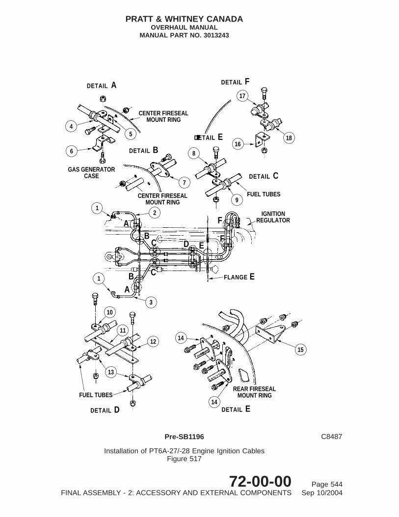
DETAIL A
DETAIL D
DETAIL C
DETAIL B
DETAIL F
DETAIL E
DETAIL E
EFLANGE
17
1618
4
6
5
CENTER FIRESEALMOUNT RING
GAS GENERATORCASE
CENTER FIRESEALMOUNT RING
12
7
8
9FUEL TUBES
AB
C
AB C
E
F
F
IGNITIONREGULATOR
1
3
D
10
11
12
13
FUEL TUBES
15
14
14
REAR FIRESEALMOUNT RING
C8487
Installation of PT6A-27/-28 Engine Ignition CablesFigure 517
Pre-SB1196
PRATT & WHITNEY CANADAOVERHAUL MANUAL
MANUAL PART NO. 3013243
72-00-00 Page 544FINAL ASSEMBLY - 2: ACCESSORY AND EXTERNAL COMPONENTS Sep 10/2004

(c) Insert flexible shaft casing (7) rearward through center fireseal mount ring,and locate seal retaining plate (12) and nut (4) on casing behind mount ring.Move casing rearward into hole in rear fireseal mount ring and install plate (12)on casing forward of center mount ring.
CAUTION: WHEN TIGHTENING CASING NUT, DO NOT ALLOW CASING TOTURN.
(d) Connect forward end of casing (7) to wire rope terminal and swivel jointassembly (21), and secure with casing nut (6) (Ref. Detail A). Tighten nut andtorque (REF. NO. 582, Table 601) and lockwire.
(e) Align hole in wire rope clamp (19) to receive wire rope (5). Push wire ropeforward from rear end and, at the same time, turn wire rope terminal assembly(20) until wire rope is fully engaged in clamp and terminal. Secure clamp (19) withspacer (29) and self-locking nut (15), and torque nut (REF. NO. 581, Fits andClearances). Ensure wire rope is in safety by inserting the end of a piece oflockwire in terminal safety hole. Rope is in safety when lockwire will not passthrough hole.
(f) Locate nut (4) mid-way on casing swivel joint (3). Insert swivel joint throughrear fireseal mount ring and connect wire rope (5) and casing (7). Securecasing to swivel joint with nut (6) fingertight (Ref. Detail C).
Key to Figure 517
1. Glow Plug2. Ignition Cable (LH)3. Ignition Cable (RH)4. Loop Clamp5. Angle Bracket6. Bracket7. Cable Flange8. Loop Clamp9. Loop Clamp
10. Loop Clamp11. Backplate12. Loop Clamp13. Loop Clamp14. Cable Flange15. Mount Ring Support Bracket16. Angle Bracket17. Loop Clamp18. Loop Clamp
PRATT & WHITNEY CANADAOVERHAUL MANUAL
MANUAL PART NO. 3013243
72-00-00 Page 545FINAL ASSEMBLY - 2: ACCESSORY AND EXTERNAL COMPONENTS Sep 10/2004

DETAIL A DETAIL B DETAIL C
DETAIL D DETAIL E DETAIL F
DETAIL G
DETAIL G
10
8
9
12
11
5
4
6
7
REAR FIRESEALMOUNT RING
3
2
PT6A−28POST−SB1337ALTERNATIVE
LOCATION
IGNITIONEXCITER
22
21
23REAR FIRESEAL
MOUNT RING18
2019
20
15 17
181314
16
FUEL TUBES
F
G
D ECB
BA
A
GAS GENERATORCASE
CENTER FIRESEALMOUNT RING
1 2
13
C8488A
Installation of PT6A-27/-28 Engine Ignition CablesFigure 518
Post-SB1196
PRATT & WHITNEY CANADAOVERHAUL MANUAL
MANUAL PART NO. 3013243
72-00-00 Page 546FINAL ASSEMBLY - 2: ACCESSORY AND EXTERNAL COMPONENTS Sep 10/2004

CAUTION: WHEN TIGHTENING CASING NUT, DO NOT ALLOW CASING TOTURN.
(g) Check that casing (7) is centralized in center fireseal mount ring hole. Screwsecond nut (4) (already on casing) onto swivel joint (3). Tighten both nutsagainst mount ring and mounting bracket and torque 95 to 105 lb.in. Torquecasing nut (6) (REF. NO. 582, Table 601). Lockwire nuts (4) and nut (6).
NOTE: Installation of nuts (4) also secures mount ring to mounting bracket(28).
(h) Assemble loop clamp (8) on casing (7) and secure to angle bracket (25) onflange C with bolt (17) and self-locking nut (15). Tighten nut and torque 36 to40 lb.in. (Ref. Detail B).
NOTE: Installation of bracket (25) was previously carried out during assemblyof power output section to gas generator assembly.
(i) Place two seals (14) on casing (7), one each side of center fireseal mount ring.
Key to Figure 518
1. Spark Igniter2. Ignition Cable (Left-hand)3. Ignition Cable (Right-hand)4. Loop Clamp5. Angle Bracket6. Angle Bracket7. Bracket8. Angle Bracket9. Loop Clamp
10. Cable Flange11. Loop Clamp12. Angle Bracket13. Loop Clamp14. Backplate15. Loop Clamp16. Loop Clamp17. Loop Clamp18. Cable Flange19. Loop Clamp20. Angle Bracket21. Mount Ring Support Bracket22. Loop Clamp23. Loop Clamp
PRATT & WHITNEY CANADAOVERHAUL MANUAL
MANUAL PART NO. 3013243
72-00-00 Page 547FINAL ASSEMBLY - 2: ACCESSORY AND EXTERNAL COMPONENTS Sep 10/2004
(j) Place two insulations (13) on casing (7), one on outside of each seal (14), withaluminized side of each insulation facing mount ring, and slits in insulationsand seals diametrically opposite.
(k) Secure two plates (12), insulations (13), seals (14) and angle bracket (18) tocenter fireseal mount ring with two bolts (17) and self-locking nuts (15), andtorque (REF. NO. 549, Fits and Clearances), (Ref. Detail C).
(l) Assemble loop clamp (8) on casing (7) forward of center fireseal mount ringand secure clamp to bracket (18) with bolt (17), washer (16) and self-lockingnut (15). Tighten nut and torque 36 to 40 lb.in. (Ref. Detail C).
NOTE: The T5 trim harness (11) will be secured to casing (7) with loopclamps (8) and (10), bolt (17), spacer (9) and self-locking nut (15)when harness is installed after engine test.
(8) Install front interconnect linkage as follows (Ref. Fig. 520):
(a) Remove two self-locking nuts (18) and washer (19) securing propeller thrustbearing cover assembly at the 1 and 2 o’clock positions (Ref. Detail D).
(b) Place guide pin bracket (17) on studs and secure with nuts (18) (Ref. Detail D),and torque (REF. NO. 188, Table 601).
(c) Locate sleeve spacer (11) in upper hole in propeller lever (15) and locate leverend in clevis of push-pull control rod front terminal (10). Insert bolt (12) throughclevis and lever, and secure with castellated nut (1). Torque nut 25 to35 lb.in. and lock with cotterpin (8) (Ref. Detail B).
(d) Install sleeve bushing (16) in center hole of lever (15); locate lever in fork ofBeta valve plunger (14) and secure with pin (13), washer (2) and cotterpin(8).
(e) Assemble washer (2), rod assembly connector (3) and second washer (2) onwire rope clamp (9) and secure with castellated nut (1). Tighten nut, torque 25to 35 lb.in. and lock with cotterpin (8) (Ref. Detail A).
(f) Position interconnect linkage fully forward against low pitch stop, and air bleedlink (4) fully forward against maximum stop. Align rear connector (3) withairbleed link (4); check that center of connector hole is approximately 1/32 inchto rear of center of outer hole in link. If necessary, adjust length of rodassembly (7).
(g) Check that both connectors (3) are in safety in rod assembly (7) by inserting apiece of lockwire in rod safety holes. Connectors are in safety if lockwire willnot pass through holes. Secure connectors (3) and nuts (6) to rod (7). Torquenuts (6) 12 to 18 lb. in. and lockwire (PWC05-089) connectors (3) and nuts(6) to rod (7).
PRATT & WHITNEY CANADAOVERHAUL MANUAL
MANUAL PART NO. 3013243
72-00-00 Page 548FINAL ASSEMBLY - 2: ACCESSORY AND EXTERNAL COMPONENTS Sep 10/2004

(h) Secure rear connector (3) to airbleed link (4) with bolt (5), washer (2) andcastellated nut (1). Torque nut 24 to 36 lb. in. and lock with cotterpin (8)(Ref. Detail A).
NOTE: Final adjustment of the low pitch stop position and rod assemblylength can only be achieved with a propeller installed.
(9) Install rear interconnect linkage as follows (Ref. Fig. 521):
(a) Remove two bolts (3) securing flange cover (12) to accessory gearbox housing.
(b) Remove two self-locking nuts (13) securing accessory gearbox to air inletcase at flange G. Locate cambox assembly (4) on two accessory gearboxstuds, followed by an electrical connector bracket (Ref. Final Assembly-1).Secure bracket and cambox with self-locking nuts (13). Tighten nuts and torque32 to 36 lb.in.
(c) Locate angle bracket (1) on accessory gearbox raised boss and cover (12);secure with two bolts (3) fingertight. Insert remaining bolt (2) in top hole ofbracket and screw into control lever mounting bracket (4). Torque each bolt 36to 40 lb.in. and lockwire.
(d) Set FCU by rotating control arm (18) fully counterclockwise, then slowly rotatearm clockwise until FCU governor cam pick-up point is felt. Set armcounterclockwise just clear of pick-up point, and retain in this position.
(e) Position of arm (18) should be approximately 16 degrees below horizontal witharm pointing rearwards.
NOTE: Sixteen degree angle is nominal for purposes of overhaul. Actualsetting may differ when engine is installed in airframe.
(f) If necessary, reset arm (18) by slackening FCU arm extension (17) and rotatingarm on serrated spacer. Tighten arm extension (17), torque (REF. NO. 598,Table 601) and lockwire.
NOTE: Serrations on FCU arm together with unequal number of serrations onfaces of spacer provide vernier adjustment in increments of 0.6degree.
(g) Rotate shaft of cambox (4) until shoulder pin of follower lever is at track pointin propeller control cam (8).
NOTE: Track point of cam slot is at the rear end of arc-shaped slot where anabrupt change in cam profile occurs.
(h) To ensure that rod assembly (16) is assembled to correct length, rod ismeasured from center of one connector to center of the other, and recorded (Ref.76-10-00). If, during installation of rod assembly (16), connectors fail to alignwith holes in FCU lever (29) and FCU arm (18), readjust in accordance withassembly procedures (Ref. 76-10-00).
PRATT & WHITNEY CANADAOVERHAUL MANUAL
MANUAL PART NO. 3013243
72-00-00 Page 549FINAL ASSEMBLY - 2: ACCESSORY AND EXTERNAL COMPONENTS Sep 10/2004

(i) Align holes in FCU lever (29) and FCU arm (18) with holes in connectors of rodassembly (16) and install bolts (7) at each end.
(j) Check each connector for safety by inserting a piece of lockwire in safety holesin rod. When lockwire will not pass through holes, connectors are in safety.
(k) Lock bolts (7), previously installed, with washer (14) and castellated nut (15).Tighten nut and torque (REF. NO. 585, Table 601) and lock with cotterpin (5).
(l) On engines with starting control, set FCU arm (18) to 16 degrees belowhorizontal (Ref. step (d) preceding). Insert rig pin (Rod 0.120 inch dia.)through hole in starting control lever (26) and into detent plate rigging slot ofstarting control (27) (RUN position is normally 72 degrees).
NOTE: The run position may be referred to as IDLE, LO-IDLE, orGROUND-IDLE, depending on installation.
CAUTION: WHEN ADJUSTING INTERCONNECT ROD, 45 DEGREE RIGGINGSLOT IN STARTING CONTROL MUST NOT BE USED UNLESS IT ISKNOWN THAT AIRFRAME INSTALLATION HAS BEEN MODIFIEDIN ACCORDANCE WITH AIRFRAME MANUFACTURERSINSTRUCTIONS.
(m) On applicable engine/aircraft installations, adjust length of control rod (23) toprovide a maximum gap of 0.030 inch at lower end of rod when rod isconnected between FCU arm and starting flow control lever (26) (Ref. Figs.521 and 522).
(n) The following substeps are provided for their informational value:
1 The RUN position (Ref. Fig. 522) on the starting control may be at 45° or72°, depending on the airframe installation, and is defined by detents orrigging slots in the plate behind the lever. Movement from 45° to 90° has noeffect on starting control operation and is provided only to actuate theFCU control arm via the telescopic rod and introduce the hi-idle function.
2 Most installations incorporating this function use the 72° RUN position. Withthe rod adjusted as above, movement of the start control lever from 72° to90° will provide approximately the correct hi-idle speed, final adjustmentbeing made by the starting control maximum stop.
3 However, for installations using the 45° RUN position, movement of thestart control lever from 45° to 90° will provide a hi-idle speed considerablyhigher than required. This must be compensated for by increasing the gap atthe lower end of the rod as required to obtain the desired rpm or,alternatively, limiting movement of the cockpit starting control lever whenselecting HI-IDLE.
(o) Tighten rod assembly (23) jam nuts (22, Fig. 521), torque 32 to 36 lb.in. andlockwire (PWC05-089).
(p) Apply a light film of grease (PWC04-001) to ball end fitting of control rodassembly (23).
PRATT & WHITNEY CANADAOVERHAUL MANUAL
MANUAL PART NO. 3013243
72-00-00 Page 550FINAL ASSEMBLY - 2: ACCESSORY AND EXTERNAL COMPONENTS Sep 10/2004

(q) Secure upper end of rod assembly (23), to FCU lever (19) with bolt (21),spacer sleeve (20), washer (14) and castellated nut (15). Tighten nut, torque 12to 18 lb.in. and lock with cotterpin (5).
(r) Secure lower end of rod assembly (23) to start control lever (26) with bolt (21),spacer sleeves (24) and (25), washer (14) and castellated nut (15). Tighten nut,torque 12 to 18 lb.in. and lock with cotterpin (5).
(s) Remove rig pin from starting control (27).
(t) Align slot in head of wire rope clamp (1, Fig. 519) in push-pull terminal (2)along length of terminal. Locate terminal over wire rope (5) and casingswivel joint (3); wind terminal onto wire rope until fully engaged with clamp (1).Secure wire rope (5) to clamp (1) with washer (30) and self-locking nut (15)and torque (REF. NO. 581, Table 601). Check that wire rope is in safety byinserting lockwire in safety hole in terminal. Rope is in safety when lockwirewill not pass through hole.
(u) Set follower lever pin to track point in cam (Ref. step (g) preceding). Applyslight pressure on terminal (2, Fig. 519) toward propeller control cam (8,Fig. 521).
(v) Adjust rod end clevis on rear terminal (11) until hole in clevis aligns with middlehole of cam (8); unscrew clevis one complete turn. Tighten jam nut (10) andtorque 38 to 42 lb.in. Check that terminal thread is in safety by inserting lockwirein clevis safety hole. Terminal is in safety when lockwire will not pass throughhole.
(w) Secure clevis of terminal (11) to cam (8) with pin (9), washer (6) and cotterpin(5).
(10) If test facility is of the non-reversing propeller configuration, connect reversingcontrols after engine final acceptance test, using procedures described in (4),(5)and (6), preceding.
(11) After complete assembly of controls, operate and check controls for full and freemovement in the correct sense.
(12) Check reversing system components are in safety and all locking devices arecorrectly secured.
I. Propeller Governor Pneumatic Tubes (Ref. Fig. 523)
(1) Remove all protective material applied on completion of overhaul (Ref. 73-10-08).
(2) Insert bulkhead coupling (9) in center fireseal mount ring (from rear side) and securewith jam nut (10). Torque nut 38 to 42 lb.in
(3) Install one seal retaining plate (5) on front end of tube (4) and slide toward rearend. Place tube loosely in slot of rear fireseal and install second plate (5).
PRATT & WHITNEY CANADAOVERHAUL MANUAL
MANUAL PART NO. 3013243
72-00-00 Page 551FINAL ASSEMBLY - 2: ACCESSORY AND EXTERNAL COMPONENTS Sep 10/2004

DETAIL A
CFLANGE
DETAIL B
DETAIL C
DETAIL D
CFLANGE
29
1520
211522
4
19
23
5
7 6 24
5
1787
27
15
25
26
12
34
28 4
15
REAR FIRESEAL
9
10
11
17
515
817 12
17 8
67
1713 14
1312
18
15
16
15
CENTER FIRESEALMOUNT RING
A
B
C
SUPPORT BRACKET
REAR FIRESEALMOUNT RING
D
POST−SB1528
PRE−SB1528
15 8 25 17
C9445E
Interconnect Linkage Group - Push-pullFigure 519
PRATT & WHITNEY CANADAOVERHAUL MANUAL
MANUAL PART NO. 3013243
72-00-00 Page 552FINAL ASSEMBLY - 2: ACCESSORY AND EXTERNAL COMPONENTS Sep 10/2004

Key to Figure 519
1. Wire Rope Clamp2. Wire Rope Terminal Assembly3. Casing Swivel Joint4. Nut5. Wire Rope6. Casing Nut7. Flexible Shaft Casing8. Loop Clamp9. Spacer
10. Loop Clamp (Ref. only)11. T5 Trim Wiring Harness (Ref. only)12. Seal Retaining Plate13. Insulation14. Seal15. Self-locking Nut16. Washer17. Bolt18. Bracket19. Wire Rope Clamp20. Wire Rope Terminal Assembly21. Adjuster and Swivel Joint Assembly22. Retaining Plate23. Engine Lifting Bracket24. Bolt25. Bracket26. D-head Bolt (Pre-SB1528)
Tee Bolt (Post-SB1528)27. Self-locking Nut (Ref.)28. Bracket29. Spacer
PRATT & WHITNEY CANADAOVERHAUL MANUAL
MANUAL PART NO. 3013243
72-00-00 Page 553FINAL ASSEMBLY - 2: ACCESSORY AND EXTERNAL COMPONENTS Sep 10/2004

15
10
7 14
15
17
18
THRUSTBEARINGCOVER
1613
129
10
6
12
38
7
65
43
21
817
14
81
11
8
2
15
DETAIL D
DETAIL B
DETAIL CDETAIL A
AB
C
D
AIRBLEEDLINK
2
C9450A
Interconnect Linkage Group - Front ComponentsFigure 520
PRATT & WHITNEY CANADAOVERHAUL MANUAL
MANUAL PART NO. 3013243
72-00-00 Page 554FINAL ASSEMBLY - 2: ACCESSORY AND EXTERNAL COMPONENTS Sep 10/2004

(4) Place insulations (6) and seals (7) (slit diametrically opposite) on pneumatic tube (4)each side of rear fireseal mount ring. Position retaining plates (5) next to insulation(6) with aluminized side of insulation facing mount ring.
(5) Connect tube (4) coupling nuts to coupling (9) and elbow (1); torque both couplingnuts 90 to 100 lb.in.
(6) Install seal retaining plate (8) between mount ring and forward seal (7); ensurejoggled portion of plate slots into fireseal.
CAUTION: BOLTS SECURING RETAINING PLATES TO REAR FIRESEAL MOUNTRING MUST HAVE THE BOLT HEADS LOCATED ON COMPRESSOR AIRINLET SIDE.
(7) Secure seal retaining plates (5) and (8), insulations (6) and seals (7) to rear firesealmount ring with two bolts and self-locking nuts. Tighten nuts and torque; (REF. NO.549, Table 601).
(8) Route electrical cable (3) across accessory gearbox and secure with loop clamp (2)to top mounting stud of fuel pump, with washer and self-locking nut. Tighten nutand torque 75 to 85 lb.in.
(9) Connect electrical cable (3) to electrical connector flange G, as described forheated pneumatic tubes (Ref. Para. K., following).
(10) Connect both ends of tube (11) to coupling (9) and nipple (14) on propellergovernor; tighten tube nuts and torque 90 to 100 lb.in.
Key to Figure 520
1. Castellated Nut2. Washer3. Rod End Connector4. Propeller Governor Airbleed Link5. Bolt6. Nut7. Rod Assembly8. Cotterpin9. Wire Rope Clamp
10. Push-pull Control Rod Terminal11. Sleeve Spacer12. Bolt13. Pin14. Beta Valve Plunger15. Propeller Lever16. Sleeve Bushing17. Guide Pin Bracket18. Self-locking Nut
PRATT & WHITNEY CANADAOVERHAUL MANUAL
MANUAL PART NO. 3013243
72-00-00 Page 555FINAL ASSEMBLY - 2: ACCESSORY AND EXTERNAL COMPONENTS Sep 10/2004

B
1716
18
PT6A−21 ENGINES VIEW C
27 2625
2421
22
23
145
15
CPT6A−27/28 ENGINES
VIEW A
VIEW B
A8
29
28 20 22 21
1415
5
16
515 14 1718
7
19
B
17
23
18
A8
29
3
2
1
6
5
29
13 4 12
8
7
FLANGE G
16
5
14 15
11 10
REAR FIRESEALMOUNT RING
9
C11796
Interconnect Linkage Group - Rear ComponentsFigure 521
PRATT & WHITNEY CANADAOVERHAUL MANUAL
MANUAL PART NO. 3013243
72-00-00 Page 556FINAL ASSEMBLY - 2: ACCESSORY AND EXTERNAL COMPONENTS Sep 10/2004
(11) Secure loop clamp (13) to angle bracket (12) with bolt and self-locking nut, and torquenut 36 to 40 lb.in.
(12) Lockwire all tube couplings and bulkhead connector after pressure test ofpneumatic tubes (Ref. Para. L., following).
J. Compressor Delivery Air Line (Ref. Figs. 525 and 526)
NOTE: Refer to Table 501 for Engine/Service Bulletin Applicability.
(1) Install pneumatic tubes and temperature compensator on PT6A-27/-28(Pre-SB1123/Post-SB1123 Alternative Mod.) engines (Ref. Fig. 525):
Key to Figure 521
1. Angle Bracket2. Bolt3. Bolt4. Control Lever Mounting Bracket5. Cotterpin6. Washer7. Bolt8. Propeller Control Cam9. Pin
10. Jam Nut11. Push-pull Wire Rope Rear Terminal12. Flange Cover13. Self-locking Nut14. Washer15. Castellated Nut16. Rod Assembly17. Fuel Control Arm Extension18. Fuel Control Arm19. FCU Lever Assembly20. Spacer Sleeve (For PT6A-27-28 Engines)21. Bolt (For PT6A-27-28 Engines)22. Jam Nut (For PT6A-27-28 Engines)23. Rod Assembly (For PT6A-27-28 Engines)24. Spacer Sleeve (For PT6A-27-28 Engines)25. Spacer Sleeve (For PT6A-27-28 Engines)26. Starting Control Lever (For PT6A-27-28 Engines)27. Starting Control (For PT6A-27-28 Engines)28. Fuel Control Unit (FCU) (Typical) (For PT6A-27-28 Engines)29. Fuel Control Lever
PRATT & WHITNEY CANADAOVERHAUL MANUAL
MANUAL PART NO. 3013243
72-00-00 Page 557FINAL ASSEMBLY - 2: ACCESSORY AND EXTERNAL COMPONENTS Sep 10/2004

HI−IDLE
F.C.U. DETAIL
LOW IDLE (RUN)
MOVEMENT
TAKE−OFF(REF.)
MOVEMENT
F.C.U. DETAIL
LOW IDLE (RUN)
HI−IDLE
°FROM 72 RUN POSITION, STARTCONTROL ARM MOVES TO 90 ,
THUS MOVING F.C.U. ARM SUFFICIENTLYTO ATTAIN HI−IDLE.
°
°
GAP 0.030
18 MOVEMENT
HI−IDLE
LOW IDLE(RUN)
0
9072
45
STARTINGCONTROL
DETAIL
HI−IDLE
°
°°
°90°
0°
STARTINGCONTROL
DETAIL
45°
RUN POSITIONMOVEMENT
PRE−SET GAP FOR 45RUN POSITION
MOVEMENT
HI−IDLE STOP
°
CUT−OFF ANDDUMP STOP
(0 REF.)°
IF GAP IS TILL SET TO 0.030 WHENUSING 45 RUN POSITION, MOVEMENTTO 90 WILL GIVE EXCESSIVELY HIGH
HI−IDLE, GAP MUST BE PRE−SET TOOBTAIN DESIRED SPEED OR COCKPIT
LEVER MOVEMENT MUST BE RESTRICTED
°°
C9216
Adjustment of Starting Control Telescopic LinkageFigure 522
PRATT & WHITNEY CANADAOVERHAUL MANUAL
MANUAL PART NO. 3013243
72-00-00 Page 558FINAL ASSEMBLY - 2: ACCESSORY AND EXTERNAL COMPONENTS Sep 10/2004
(a) Remove all protective material applied on completion of overhaul (Ref.73-10-07).
(b) Install straight nipple (12) with preformed packing (13) in compensator (15) orcompensator body (14). Tighten nipple and torque to 65 to 75 lb.in.
(c) Install elbow (21) with preformed packing (18), back-up ring (19) and locknut(20). Tighten locknut, torque 38 to 42 lb.in. and lockwire.
(d) Install seal (17) and insulation (16), aluminized side facing fireseal on studs ofcompensator (15) or compensator body (14). Install seal (24), insulation (23),aluminized side facing fireseal, and retaining plate (22) on elbow (21).
(e) Install compensator (15) or compensator body (14) on rear face of rear firesealand install seal (25) and retaining plate (26) over protruding ends of compensator(15) or studs of body (14).
(f) Install seal (24), insulation (23), aluminized side facing fireseal, and retainingplate (22) over protruding elbow (21).
CAUTION: HEADS OF BOLTS SECURING RETAINING PLATES TO REARFIRESEAL MUST FACE COMPRESSOR AIR INLET SIDE.
(g) Secure compensator (15) or body (14) with two bolts (30) and two self-lockingnuts at elbow and two self-locking nuts at studs. Tighten nuts; torque 36 to40 lb.in. at elbow and 32 to 36 lb.in. at studs.
(h) Connect compressor delivery pneumatic heated tube (6) to nipple (12) oncompensator (15) or compensator body (14), and to elbow (4) on fuelcontrol unit. Tighten locknut (3) and torque 38 to 42 lb.in., at the same timeholding elbow (5) in position. Tighten tube coupling nuts and torque to 90 to100 lb.in.
(i) Connect electrical cable to electrical connector at flange G, as described forinstallation of heated pneumatic tubes (Ref. Para. K.. following).
(j) Complete installation of compressor delivery tubes will be accomplishedfollowing pressure testing of pneumatic tubes (Ref. Para. L.. following).
(2) Install pneumatic tubes (without temperature compensator) on PT6A-27/-28Post-SB1123, Stnd. Mod) and all PT6A-21 engines, as follows (Ref. Fig. 526):
(a) Remove all protective material applied on completion of overhaul (Ref. 73-10-07).
(b) Install one seal retaining plate (3) over heated tube (11) and slide rearwardto center of tube. Position tube loosely in slot of rear fireseal mount ring, andinstall second seal retaining plate (3).
(c) Place insulations (4) and seals (5) (slits diametrically opposite) on tube (11),each side of rear fireseal. Position retaining plates (3) next to insulation (4),aluminized side of insulation facing fireseal.
PRATT & WHITNEY CANADAOVERHAUL MANUAL
MANUAL PART NO. 3013243
72-00-00 Page 559FINAL ASSEMBLY - 2: ACCESSORY AND EXTERNAL COMPONENTS Sep 10/2004

4
2
3
1
FUEL CONTROL UNIT
4
9
10
CENTER FIRESEALMOUNT RING
11
14
11
12
13
TO PROPELLERGOVERNOR
CFLANGE
5 6 7 8
76 5REAR FIRESEAL
MOUNT RING
C7469A
Installation of Propeller Governor Pneumatic TubesFigure 523
PRATT & WHITNEY CANADAOVERHAUL MANUAL
MANUAL PART NO. 3013243
72-00-00 Page 560FINAL ASSEMBLY - 2: ACCESSORY AND EXTERNAL COMPONENTS Sep 10/2004

(d) Connect electrical cable (2) to electrical connector at flange G, as describedfor installation of heated pneumatic tubes (Ref. Para.K., following).
(e) Complete installation of compressor delivery tube will be accomplishedfollowing pressure testing of pneumatic tubes (Ref. Para. L., following).
(3) Install pneumatic tubes and air filter on PT6A-27/-28 Post-SB1205 engines, asfollows (Ref. Fig. 527):
(a) Remove all protective material applied on completion of overhaul (Ref.73-10-07).
(b) Secure support bracket (5) to studs on flange G with three self-locking nuts.Tighten two lower nuts and torque 36 to 40 lb.in.
(c) Install air filter (6) (arrow on filter pointing toward rear of engine) on bracket (5)and secure with locknut (4). Tighten nut and torque 38 to 42 lb.in.
(d) Assemble heated tube (3) on elbow of fuel control unit and air filter (6). Torqueboth coupling nuts 90 to 100 lb.in.
(e) Connect electrical cable (2) to electrical connector at flange G, as described forinstallation of heated pneumatic tubes (Ref. Para. K. following).
(f) Install one seal retaining plate (7) over insulated tube (13) and slide rearwardto first bend in tube. Position tube loosely in slot of rear fireseal mount ring,and install second seal retaining plate (7).
(g) Place insulations (8) and seals (9) (slits diametrically opposite) on tube (13) ateach side of rear fireseal. Position retaining plates (7) next to insulation (8),aluminized side of insulation facing fireseal.
Key to Figure 523
1. Elbow (on FCU)2. Loop Clamp3. Electrical Cable4. Governor Pneumatic Tube - Heated5. Seal Retaining Plate6. Insulation7. Seal8. Seal Retaining Plate9. Bulkhead Coupling
10. Jam Nut11. Governor Pneumatic Tube - Front12. Angle Bracket13. Loop Clamp14. Straight Nipple
PRATT & WHITNEY CANADAOVERHAUL MANUAL
MANUAL PART NO. 3013243
72-00-00 Page 561FINAL ASSEMBLY - 2: ACCESSORY AND EXTERNAL COMPONENTS Sep 10/2004
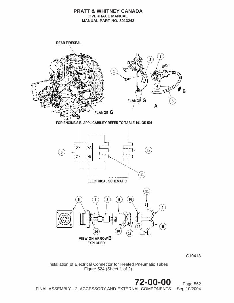
VIEW ON ARROW B
6 7 8 9 16
11
4
514 10 13
12
EXPLODED
B
6D
C
A
B
ELECTRICAL SCHEMATIC
11
12
AGFLANGE
A
FOR ENGINE/S.B. APPLICABILITY REFER TO TABLE 101 OR 501
GFLANGE
REAR FIRESEAL
1
23
4
5
C10413
Installation of Electrical Connector for Heated Pneumatic TubesFigure 524 (Sheet 1 of 2)
PRATT & WHITNEY CANADAOVERHAUL MANUAL
MANUAL PART NO. 3013243
72-00-00 Page 562FINAL ASSEMBLY - 2: ACCESSORY AND EXTERNAL COMPONENTS Sep 10/2004

Key to Figure 524
1. Screw2. Bracket3. Electrical Connector4. Governor Pneumatic Heated Tube Electrical Cable5. Compressor Delivery Pneumatic Heated Tube Electrical
Cable (Sheet 1) Compressor Delivery Pneumatic HeatedTube Electrical Cable and Compressor Delivery PneumaticHeated Center Tube Electrical Cable (Sheet 2)
6. Connector Shell7. Rubber Insulator8. Nylon Sleeve9. Bell-end Fitting
10. Clamp Screw11 Element in Governor Pneumatic Heated Tube12. Element in Compressor Delivery Pneumatic Heated Tube13. Cable Sleeve14. Pins15. Element in Compressor Delivery Pneumatic Heated Center
Tube16. Loop Clamp and Rubber Grommet
PRATT & WHITNEY CANADAOVERHAUL MANUAL
MANUAL PART NO. 3013243
72-00-00 Page 563FINAL ASSEMBLY - 2: ACCESSORY AND EXTERNAL COMPONENTS Sep 10/2004

DETAIL AGFLANGE
GFLANGE
BA
REAR FIRESEAL
1
23
5
4
D AC B
ELECTRICAL SCHEMATIC
15
6 12
1115
4
5
11
98
13
12
16
107
14
EXPLODED VIEW ON ARROW B
A
BC
D
6
C8495B
Installation of Electrical Connector for Heated Pneumatic TubesFigure 524 (Sheet 2)
PRATT & WHITNEY CANADAOVERHAUL MANUAL
MANUAL PART NO. 3013243
72-00-00 Page 564FINAL ASSEMBLY - 2: ACCESSORY AND EXTERNAL COMPONENTS Sep 10/2004

(h) Complete installation of compressor delivery tube will be accomplishedfollowing pressure testing pneumatic tubes (Ref. Para. L., following).
(4) Install pneumatic tubes and bowl-type filter on PT6A-28 Post-SB1290 engines, asfollows (Ref. Fig. 528):
(a) Install bracket (4) on flange G (Ref. Final Assembly-1, Fig. 502) and securewith two self-locking nuts (5). Tighten nuts and torque 32 to 36 lb.in.
(b) Install P3 filter assembly (15) on bracket (4) and, with loop clamp (8) locatedon electrical cable, secure clamp and filter assembly with bolts (9), washerand self-locking nuts to bracket (4). Tighten nuts and torque 36 to 40 lb.in.
(c) Attach one end of heated hose (16) to elbow (17) on FCU and the other end toelbow on P3 filter assembly (15). Tighten both coupling nuts, torque 90 to100 lb.in.
(d) Assemble plate (10) on rear fireseal (forward side) at slot location; secure withtwo bolts and self-locking nuts and torque 32 to 36 lb.in.
(e) Insert nipple end of heated center tube (1) forward through plate (10) andsecure with locknut (11); secure coupling nut at other end of center tube toelbow on P3 air filter assembly (15).
(f) Tighten center tube coupling nut at one end and torque 90 to 100 lb.in; tightenlocknut (11) at the other end and torque 38 to 42 lb.in.
(g) Connect electrical cables (2) and (3) to electrical connector at flange G (Ref.Para. K., following).
(h) Completion of assembly of this system will be accomplished following pressuretesting of the pneumatic tubes (Ref. Para. L.).
(5) Install pneumatic tubes and bowl-type filter (Post-SB1330/Post-SB1378 engines) asfollows (Ref. Fig. 529):
(a) Install bracket (4) on flange G (Ref. Final Assembly-1, Fig. 502) and securewith nut on lower stud.
(b) Install spacers (20) and (18) and bracket (6). Fit self-locking nuts (5), tightenand torque 32 to 36 lb.in.
(c) Install P3 filter assembly (14) on bracket (4) and, with one washer, one anglebracket (17) (Post-SB1330 only), two bolts (8) and self-locking nuts, secureangle bracket and filter assembly to bracket (4). Tighten nuts and torque 36 to40 lb.in.
(d) On Post-SB1583 engines, install P3 filter assembly (14) on bracket (4) and,with four washers, one angle bracket (17) (Post-SB1330 only), two bolts (23)and self-locking nuts, secure angle bracket and filter assembly to bracket (4).Tighten nuts and torque 36 to 40 lb.in.
PRATT & WHITNEY CANADAOVERHAUL MANUAL
MANUAL PART NO. 3013243
72-00-00 Page 565FINAL ASSEMBLY - 2: ACCESSORY AND EXTERNAL COMPONENTS Sep 10/2004

(e) Assemble plate (9) on fireseal (forward side) at slot location; secure with twobolts and self-locking nuts and torque 36 to 40 lb.in.
(f) Insert nipple end of heated tube (1) forward through plate (9) and secure withlocknut (10); secure coupling nut at other end of tube to elbow on P3 air filterassembly (14).
(g) Tighten tube locknut (10) and torque 38 to 42 lb.in.; tighten coupling nut atother end of tube and torque 90 to 100 lb.in.
(h) Attach one end of heated tube (15) to elbow (16) on FCU and the other end toelbow on P3 filter assembly (14). Tighten both coupling nuts and torque 90 to100 lb.in.
(i) Connect electrical cables (2) and (3) to electrical connector at flange G (Ref.Para. K., following).
(j) Completion of assembly of this system will be accomplished following pressuretesting of the pneumatic tubes (Ref. Para. L.).
(6) Install pneumatic tubes and bowl-type filter (PT6A-27/-28 Engines Post-SB1343) asfollows (Ref. Fig. 530):
(a) Install spacers (5) and bracket (4) on flange G (Ref. Final Assembly-1, Fig.502) with two self-locking nuts. Torque nuts 36 to 40 lb.in.
(b) Install P3 filter assembly (18) on bracket (4) and, with loop clamp (16) locatedon electrical cable, with bolts (17), washers and self-locking nuts. Torque nuts32 to 36 lb.in.
(c) On Post-SB1583 engines, install P3 filter assembly (18) on bracket (4) and,with loop clamp (16) located on electrical cable, with Tee bolts (21), fourwashers and self-locking nuts. Torque nuts 32 to 36 lb.in.
(d) Attach one end of heated hose (19) to elbow (20) on FCU and the other end toP3 air filter assembly (18). Torque both coupling nuts 90 to 100 lb.in.
(e) Assemble plate (15) on rear of rear fireseal mount ring at slot location with twobolts (9) and self-locking nuts. Torque 32 to 36 lb.in.
(f) Insert nipple end of center insulated tube (1) forward through plate (15) withlocknut (14); attach coupling nut at other end of tube to elbow on P3 air filterassembly (18).
(g) Torque center tube coupling nut at filter 90 to 100 lb.in., torque locknut (14) 38to 42 lb.in.
(h) Connect electrical cable (2) to electrical connector at flange G (Ref. Para. K.).
(i) Completion of assembly of this system will be accomplished followingpressure testing of pneumatic tubes (Ref. Para. L.)
PRATT & WHITNEY CANADAOVERHAUL MANUAL
MANUAL PART NO. 3013243
72-00-00 Page 566FINAL ASSEMBLY - 2: ACCESSORY AND EXTERNAL COMPONENTS Sep 10/2004

(7) Install pneumatic hoses, tube and bowl type filter (PT6A-27/-28 engines,Post-SB1448) as follows (Ref. Fig. 531):
(a) Assemble, at rear fireseal mount ring slot location, tube retaining plate (10) onrear and seal retaining plate (9) on front with bolts and self-locking nuts. Torquenuts 32 to 36 lb.in.
(b) Install washer (11) on elbow (12), insert elbow through retaining plates (10and 9) on rear fireseal mount ring with locknut (5). Torque nut 38 to 42 lb.in.
(c) Install P3 filter assembly (4) on bracket assembly (1) mounted on flange G,with bolts (3) and self-locking nuts. Torque nuts 32 to 36 lb.in.
(d) Attach center heated hose (13) with electric cable (14) to elbow (12) on rearfireseal mount ring and other end to P3 filter assembly (4) inner elbow (19).Torque coupling nuts 90 to 100 lb.in.
(e) Attach rear heated hose (16) with electric cable (15) to P3 filter assembly (4)outer elbow (18) and other end to elbow (17) on FCU. Torque coupling nuts 90to 100 lb.in.
(f) Install electrical connector (2) to bracket assembly (1) (Ref. Para. K.).
(g) Attach insulated tube (6) coupling nut to elbow (12) on rear fireseal mount ring.Align gasket (7) between flange end of tube and gas generator case boss,insert bolts (8) through flange and gasket into boss and tighten.
(h) Completion of system assembly will be accomplished following testing (Ref.Para. L.).
K. Installation of Electrical Connector from Heated Pneumatic Tube (Ref. Fig. 524)
(1) After installation of pneumatic heated tubes, route leads to electrical connector andsolder as follows:
(a) Insert leads through loop clamp and rubber grommet (16), cable sleeve (13),bell-end fitting (9), nylon sleeve (8) and relevant holes in rubber insulator (7).
NOTE: Electrical leads from element (11) in Py heated tube connect to pins Aand C, and leads from element (12) in P3 heated tube connect to pinsB and D. Leads from element (15) (Ref. Fig. 524, Sheet 2) connectto pins B and D also.
(b) Using a suitable soldering iron, solder leads to connector pin (14) solderbuckets, using solder (PWC05-205) and resin flux (PWC05-031).
(c) Slide rubber insulator (7) and nylon sleeve (8) over solder connections, positionbell-end fitting (9) over sleeve and secure to connector (6), fingertight.
PRATT & WHITNEY CANADAOVERHAUL MANUAL
MANUAL PART NO. 3013243
72-00-00 Page 567FINAL ASSEMBLY - 2: ACCESSORY AND EXTERNAL COMPONENTS Sep 10/2004

28
29
GAS GENERATOR CASE
27
26
25
24 2322
30
14 SB1123 ALTERNATIVE MOD.
8
7
9 10
ACCESSORY GEARBOX FLANGE
12
34
6
FUEL CONTROL UNITELBOW ASSEMBLY
5
1112
1315
19
20
21
18
1617
2223
24
PRE−SB1123 REAR FIRESEAL
C8484A
Installation of Compressor Delivery Air Line - PT6A-27/-28 Pre-SB1123/Post-SB1123 AlternativeMod.) Engines
Figure 525
PRATT & WHITNEY CANADAOVERHAUL MANUAL
MANUAL PART NO. 3013243
72-00-00 Page 568FINAL ASSEMBLY - 2: ACCESSORY AND EXTERNAL COMPONENTS Sep 10/2004

CAUTION: DO NOT ALLOW LEADS TO TURN WHEN TIGHTENINGBELL-END FITTING.
(d) Install leads and cable sleeve with cable clamp, and clamp halves with screws(10).
(e) Install connector assembly (3) in bracket (2), with four screws (1), washers andself-locking nuts; torque nuts 7 to 8 lb.in. Install loop clamp (16) to bracket (2)Post-SB1330 or angle bracket Post-SB1330 with bolt and self-locking nut.Torque nut 36 to 42 lb.in.
Key to Figure 525
1. Preformed Packing2. Back-up Ring3. Locknut4. ElbowPre-SB 1123 or Elbow Post-SB11235. Metered Elbow ( Post-SB1123, Alternative Mod.)6. Compressor Delivery Pneumatic Heated Tube7. Spacer8. Electrical Receptacle Bracket9. Electrical Receptacle
10. Loop Clamp11. Loop Clamp and Rubber Grommet12. Straight Nipple13. Preformed Packing14. Compensator Body (Post-SB1123, Part B)15. Temperature Compensator (Pre-SB1123 Alternative Mod.)16. Insulation17. Seal18. Preformed Packing19. Back-up Ring20. Locknut21. Elbow22. Retaining Plate23. Insulation24. Seal25. Insulation26. Retaining Plate and Insulation27. Compressor Delivery Pneumatic Insulated Tube28. Gasket Pre-SB1276 or Corrugated Steel Gasket
Post-SB127629. Angle BracketPost-SB119630. Bolt 0.190-32 UNJF x 0.625 inch Alternative; Bolt 0.190-32
UNJF x 0.750 inch
PRATT & WHITNEY CANADAOVERHAUL MANUAL
MANUAL PART NO. 3013243
72-00-00 Page 569FINAL ASSEMBLY - 2: ACCESSORY AND EXTERNAL COMPONENTS Sep 10/2004
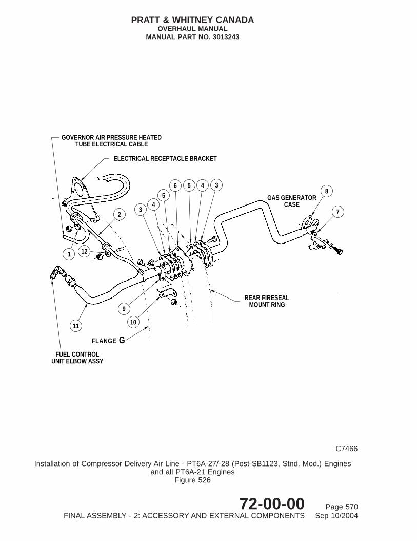
8
7
GAS GENERATORCASE
REAR FIRESEALMOUNT RING
34565
43
ELECTRICAL RECEPTACLE BRACKET
GOVERNOR AIR PRESSURE HEATEDTUBE ELECTRICAL CABLE
2
1 12
11
9
10
GFLANGE
FUEL CONTROLUNIT ELBOW ASSY
C7466
Installation of Compressor Delivery Air Line - PT6A-27/-28 (Post-SB1123, Stnd. Mod.) Enginesand all PT6A-21 Engines
Figure 526
PRATT & WHITNEY CANADAOVERHAUL MANUAL
MANUAL PART NO. 3013243
72-00-00 Page 570FINAL ASSEMBLY - 2: ACCESSORY AND EXTERNAL COMPONENTS Sep 10/2004

(f) On PT6A-28 Pre-SB1290 and all PT6A-21/-27 engines, using a turbinetemperature indicating test set or suitable ohmmeter, measure electricalresistance between connector pins of tube heater elements (Ref. Table 502).
(g) On PT6A-28 engines Post-SB1290, using a turbine temperature indicating testset or suitable ohmmeter, measure electrical resistance between connectorpins of tube heater elements. (Ref. Table 502).
NOTE: Because leads of rear and center heated tubes are soldered to thesame connector pins, both tube heater elements are checkedtogether, (their resistance values must be combined for the purpose ofthe above checks). Refer to Table 502 for individual tube assemblyresistance values.
Key to Figure 526
1. Loop Clamp2. Compressor Delivery Pneumatic Heated Tube Electrical
Cable3. Seal Retaining Plate4. Insulation5. Seal6. Seal Retaining Plate Post-SB11627. Angle Bracket (engines with spark ignition system)8. Gasket Pre-SB1276 or Corrugated Steel Gasket
Post-SB12769. Loop Clamp
10. Angle Bracket (engines with spark ignition only)11. Compressor Delivery Pneumatic Heated Tube12. Loop Clamp and Rubber Grommet
PRATT & WHITNEY CANADAOVERHAUL MANUAL
MANUAL PART NO. 3013243
72-00-00 Page 571FINAL ASSEMBLY - 2: ACCESSORY AND EXTERNAL COMPONENTS Sep 10/2004

1311
12 GAS GENERATORCASE
GFLANGE
3
4
5
6
78910
98
7
2
1
ELECTRICAL RECEPTACLEBRACKET
GOVERNOR AIR PRESSURE HEATEDTUBE ELECTRICAL CABLE
FUEL CONTROLUNIT ELBOW ASSEMBLY
REAR FIRESEALMOUNT RING
14
C8508
Installation of Compressor Delivery Air Line - PT6A-27/-28 (Post-SB1205) EnginesFigure 527
PRATT & WHITNEY CANADAOVERHAUL MANUAL
MANUAL PART NO. 3013243
72-00-00 Page 572FINAL ASSEMBLY - 2: ACCESSORY AND EXTERNAL COMPONENTS Sep 10/2004

TABLE 501, Engine/Service Bulletin Applicability
Engine Model Service Bulletin No. Fig. No. Sheet No.
PT6A-21 Pre-SB1330 531 1
Post-SB1330 531 2
PT6A-27 Pre-SB1123 531 1
Post-SB1123(Stnd or Alt Mod) 531 1
Post-SB1205 531 1
Post-SB1330 531 2
Post-SB1343 531 1
Post-SB1378 531 2
Post-SB1448 531 2
PT6A-28 Pre-SB1123 531 1
Post-SB1123(Stnd or Alt Mod) 531 1
Post-SB1205 531 1
Post-SB1290 531 2
Post-SB1314 531 2
Post-SB1330 531 2
Post-SB1343 531 1
Post-SB1448 531 2
Key to Figure 527
1. Loop Clamp2. Compressor Delivery Pneumatic Heated Tube Electrical
Cable3. Compressor Delivery Pneumatic Heated Tube4. Locknut5. Support Bracket6. Air Filter7. Seal Retaining Plate8. Insulation9. Seal
10. Seal Retaining Post-SB116211. Angle Bracket (engines with spark ignition only)12. Gasket Pre-SB1276 or Corrugated Steel Gasket
Post-SB127613. Compressor Delivery Insulated Tube14. Loop Clamp and Rubber Grommet
PRATT & WHITNEY CANADAOVERHAUL MANUAL
MANUAL PART NO. 3013243
72-00-00 Page 573FINAL ASSEMBLY - 2: ACCESSORY AND EXTERNAL COMPONENTS Sep 10/2004

12
13
14
IGNITION CABLE
16
17
FUEL CONTROL UNITELBOW ASSEMBLY
1
2 3
5
4
6
7
ELECTRICAL RECEPTACLEBRACKET
GOVERNOR AIR PRESSUREHEATED TUBE ELECTRICAL
CABLE
8 910
11
15
C8485
Installation of Compressor Delivery Air Line - PT6A-28 Post-SB1290 EnginesFigure 528
PRATT & WHITNEY CANADAOVERHAUL MANUAL
MANUAL PART NO. 3013243
72-00-00 Page 574FINAL ASSEMBLY - 2: ACCESSORY AND EXTERNAL COMPONENTS Sep 10/2004

TABLE 502, Electrical Resistance Check
Tube Heater Element Tube Ass P/N pin Coding Min. (Ohms) Res. Max. (ohms) Res.
Py 3011843 A and C 7.6 8.4
P3 3011853 B and D 18.6 21.4
P3 3014216 B and D 18.6 21.4
P3 3021964 B and D 12.0 14.0
Py 3027974 A and C 7.6 8.4
P3 3028907 B and D 18.6 21.4
P3 3030517 B and D 33.0 37.0
P3 3030522 B and D 38.0 42.0
P3 3031439 B and D 24.7 27.3
P3 3031445 B and D 38.0 42.0
P3 3031448 B and D 38.0 42.0
P3 3031850 B and D 17.1 18.9
P3 3031943 B and D 38.0 42.0
P3 3032097 B and D 24.0 28.0
P3 3032309 B and D 37.0 41.0
Key to Figure 528
1. Compressor Delivery Pneumatic Heated Center Tube2. Electrical Cable3. Electrical Cable4. Bracket5. Nut6. Electrical Receptacle Bracket7. Loop Clamp8. Loop Clamp and Rubber Grommet9. Bolt
10. Plate11. Locknut12. Compressor Delivery Pneumatic Insulated Tube13. Gasket Pre-SB1276 Corrugated Steel Gasket Pre-SB127614. Angle Bracket (engines with spark ignition only)15. P3 Air Filter16. Compressor Delivery Pneumatic Heated Hose17. Elbow
PRATT & WHITNEY CANADAOVERHAUL MANUAL
MANUAL PART NO. 3013243
72-00-00 Page 575FINAL ASSEMBLY - 2: ACCESSORY AND EXTERNAL COMPONENTS Sep 10/2004

14
78
POST−SB1378
186
5
4
20
14
17
19
7 8
15
32
1
16TO FUEL
CONTROL 910
12
1311
23
22
144
2122
22
DETAIL APOST−SB1583
A
C79904
Installation of Compressor Delivery Air Line Post-SB1330/Post-SB1378Figure 529
PRATT & WHITNEY CANADAOVERHAUL MANUAL
MANUAL PART NO. 3013243
72-00-00 Page 576FINAL ASSEMBLY - 2: ACCESSORY AND EXTERNAL COMPONENTS Sep 10/2004

L. Pressure Test Pneumatic Tubes
(1) Pressure test pneumatic lines and temperature compensator Pre-SB1123/Post-SB1123Alternative Mod.) on PT6A-27/-28 engines, as follows (Ref. Fig. 525):
(a) Connect a supply of clean dry compressed air at 80 ± 5 psig to elbow atforward end of temperature compensator (15) or compensator body (14).
(b) Apply leak-checking fluid (PWC05-007) to entire surface of all connectingpoints throughout pneumatic system. No leaks are permitted other thanfrom two bleed holes in fuel control unit and one bleed hole in propeller governor.
(c) Rectify any leakage and repeat pressure test.
(d) When pressure test is satisfactory, wipe off all traces of leak detecting fluid.
(e) Disconnect air supply.
(f) Install applicable gasket (28) under flange of insulated tube (27), and locatetube between elbow connector on compensator (15) or compensator body(14).
Key to Figure 529
1. Compressor Delivery Pneumatic Heated Center Tube2. Electrical Cable3. Electrical Cable4. Bracket5. Nut6. Electrical Receptacle Bracket7. Loop Clamp8. Bolt9. Plate
10. Locknut11. Compressor Delivery Pneumatic Insulated Tube12. Gasket13. Angle Bracket (engine with spark ignition only)14 P3 Air Filter15. Compressor Delivery Pneumatic Heated Hose16. Elbow17. Angle Bracket Post-SB133018. Spacer19. Bolt20. Spacer21. Nut22. Washer23. Bolt
PRATT & WHITNEY CANADAOVERHAUL MANUAL
MANUAL PART NO. 3013243
72-00-00 Page 577FINAL ASSEMBLY - 2: ACCESSORY AND EXTERNAL COMPONENTS Sep 10/2004

20
19
FUEL CONTROL UNITELBOW ASSEMBLY
1013
11
12
IGNITION CABLE
GFLANGE
18
1617
1
2
6
3
7
54
8
9
1514
REAR FIRESEALMOUNT RING
ELECTRICAL RECEPTACLE BRACKET
GOVERNOR AIR PRESSURE HEATEDTUBE ELECTRICAL CABLE
APRE−SB1583
ADETAILPOST−SB1583
22 2318
16
21
22
4
GFLANGE
C10264A
Installation of Compressor Delivery Air Line - PT6A-27/-28 Post-SB1343 EnginesFigure 530
PRATT & WHITNEY CANADAOVERHAUL MANUAL
MANUAL PART NO. 3013243
72-00-00 Page 578FINAL ASSEMBLY - 2: ACCESSORY AND EXTERNAL COMPONENTS Sep 10/2004
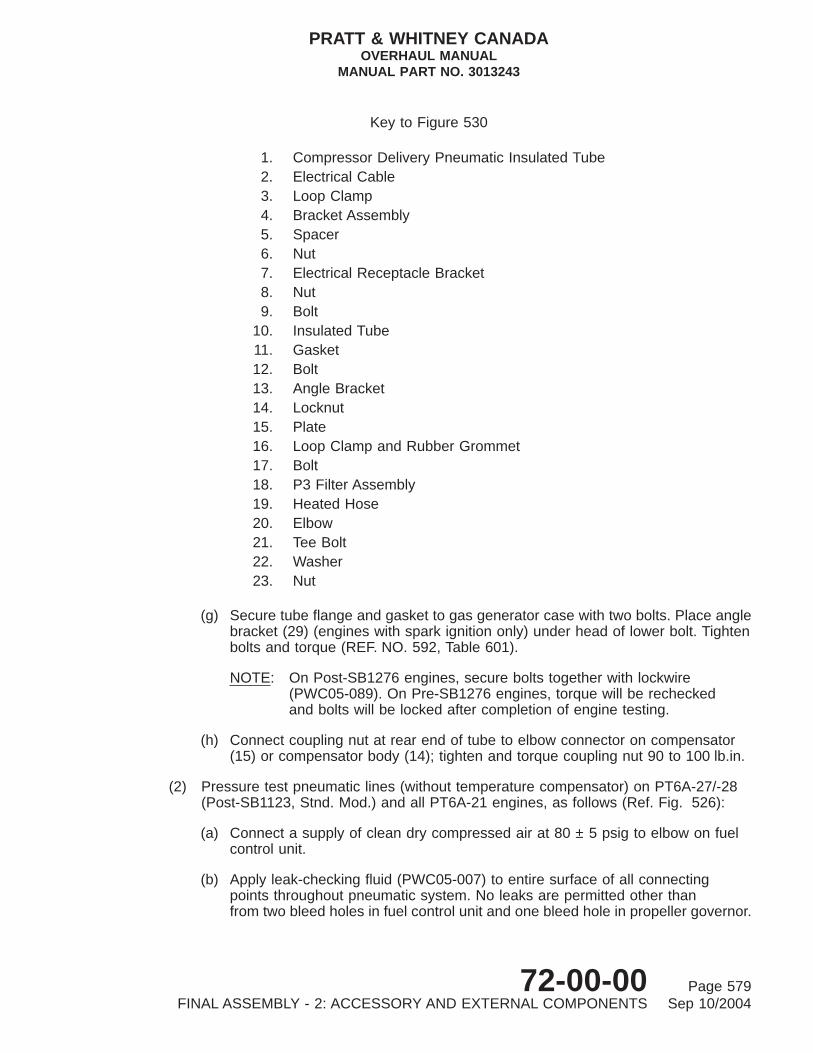
(g) Secure tube flange and gasket to gas generator case with two bolts. Place anglebracket (29) (engines with spark ignition only) under head of lower bolt. Tightenbolts and torque (REF. NO. 592, Table 601).
NOTE: On Post-SB1276 engines, secure bolts together with lockwire(PWC05-089). On Pre-SB1276 engines, torque will be recheckedand bolts will be locked after completion of engine testing.
(h) Connect coupling nut at rear end of tube to elbow connector on compensator(15) or compensator body (14); tighten and torque coupling nut 90 to 100 lb.in.
(2) Pressure test pneumatic lines (without temperature compensator) on PT6A-27/-28(Post-SB1123, Stnd. Mod.) and all PT6A-21 engines, as follows (Ref. Fig. 526):
(a) Connect a supply of clean dry compressed air at 80 ± 5 psig to elbow on fuelcontrol unit.
(b) Apply leak-checking fluid (PWC05-007) to entire surface of all connectingpoints throughout pneumatic system. No leaks are permitted other thanfrom two bleed holes in fuel control unit and one bleed hole in propeller governor.
Key to Figure 530
1. Compressor Delivery Pneumatic Insulated Tube2. Electrical Cable3. Loop Clamp4. Bracket Assembly5. Spacer6. Nut7. Electrical Receptacle Bracket8. Nut9. Bolt
10. Insulated Tube11. Gasket12. Bolt13. Angle Bracket14. Locknut15. Plate16. Loop Clamp and Rubber Grommet17. Bolt18. P3 Filter Assembly19. Heated Hose20. Elbow21. Tee Bolt22. Washer23. Nut
PRATT & WHITNEY CANADAOVERHAUL MANUAL
MANUAL PART NO. 3013243
72-00-00 Page 579FINAL ASSEMBLY - 2: ACCESSORY AND EXTERNAL COMPONENTS Sep 10/2004

56
9
7
8
REAR FIRESEALMOUNT RING
GFLANGE
2
13
1211
10
14
19
18
17
16
15
4
3
1
C42271
Installation of Compressor Delivery Air Lines -PT6A-27/28 Post-SB1448 EnginesFigure 531
PRATT & WHITNEY CANADAOVERHAUL MANUAL
MANUAL PART NO. 3013243
72-00-00 Page 580FINAL ASSEMBLY - 2: ACCESSORY AND EXTERNAL COMPONENTS Sep 10/2004

(c) Rectify any leakage and repeat pressure test.
(d) When pressure test is satisfactory, wipe off all traces of leak detecting fluid.
(e) Disconnect air supply.
(f) Install gasket (8) Pre-SB1276, or corrugated steel gasket (8) Post-SB1276under flange of heated tube (11), and locate tube between elbow on fuelcontrol unit and boss on gas generator case.
(g) Secure tube flange and gasket to gas generator case with two bolts. Onengines with spark ignition system, place angle bracket (7) under head of lowerbolt. Tighten bolts and torque (REF. NO. 592, Table 601).
NOTE: On Post-SB1276 engines, secure bolts together with lockwire(PWC05-089). On Pre-SB1276 engines, torque will be recheckedand bolts will be locked after completion of engine testing.
(h) Connect coupling nut at rear end of tube to elbow on fuel control unit, tightenand torque coupling nut 90 to 100 lb.in.
Key to Figure 531
1. Bracket Assembly2. Electrical Connector3. Bolt4. P3 Air Filter Assembly5. Locknut6. Insulated Tube7. Gasket8. Bolt9. Plate, Seal Retaining
10. Plate, Tube Retaining11. Washer12. Elbow13. Center Heated Hose Assembly14. Electrical Cable, Center hose15. Electrical Cable, Rear Hose16. Rear Heated Hose Assembly17. Elbow, FCU18. Outer Elbow19. Inner Elbow
PRATT & WHITNEY CANADAOVERHAUL MANUAL
MANUAL PART NO. 3013243
72-00-00 Page 581FINAL ASSEMBLY - 2: ACCESSORY AND EXTERNAL COMPONENTS Sep 10/2004

CAUTION: HEADS OF BOLTS SECURING RETAINING PLATES TO REARFIRESEAL MUST FACE COMPRESSOR AIR INLET SIDE.
(i) Install seal retaining plate (6) between rear fireseal and rear seal (5). Secureplates (6) and (3), insulations (4) and seals (5) to fireseal with two bolts andself-locking nuts. Angle bracket (10) is positioned under lower nut. Tighten nutsand torque (REF. NO. 549, Table 601).
(j) Assemble loop clamp (9) on heated tube (11) and secure to bracket (10) withbolt and self-locking nut. Tighten nut and torque 36 to 40 lb.in.
(k) Position loop clamp (12) and loop clamp and rubber grommet (1) on electricalcable (2) and secure to studs on flange G with self-locking nuts. Tighten andtorque nuts 32 to 36 lb.in.
(3) Pressure test pneumatic lines and air filter on PT6A-27/-28 Post-SB1205 engines,as follows (Ref. Fig. 527):
(a) Connect a supply of clean dry compressed air at 80 ± 5 psig to connector atforward end of air filter (6).
(b) Apply leak-checking fluid (PWC05-007) to entire surface of all connectingpoints throughout pneumatic system. No leaks are permitted other thanfrom two bleed holes in fuel control unit and one bleed hole in propeller governor.
(c) Rectify any leakage and repeat pressure test.
(d) When pressure test is satisfactory, wipe off all traces of leak detection fluid.
(e) Disconnect air supply.
(f) Install gasket (12)Pre-SB1276, or corrugated steel gasket (12) Post-SB1276under flange of insulated tube (13), and locate tube between connector onfilter (6) and boss on gas generator case.
(g) Secure tube flange and gasket to gas generator case with two bolts. Placeangle bracket (11) (engines with spark ignition system) under head of lowerbolt. Tighten bolts and torque (REF. NO. 592, Table 601).
NOTE: On Post-SB1276 engines, secure bolts together with lockwire. OnPre-SB1276 engines, torque will be rechecked and bolts will be lockedafter completion of engine testing.
(h) Connect coupling nut at rear end of tube to connector on air filter, tighten andtorque coupling nut 90 to 100 lb.in., and lockwire.
CAUTION: HEADS OF BOLTS SECURING RETAINING PLATES TO REARFIRESEAL MUST FACE COMPRESSOR AIR INLET SIDE.
(i) Install seal retaining plate (10) between rear fireseal and rear seal (9). Secureplates (7) and (10), insulations (8) and seals (9) to fireseal with two bolts andself-locking nuts. Tighten nuts and torque (REF. NO. 549, Table 601).
PRATT & WHITNEY CANADAOVERHAUL MANUAL
MANUAL PART NO. 3013243
72-00-00 Page 582FINAL ASSEMBLY - 2: ACCESSORY AND EXTERNAL COMPONENTS Sep 10/2004

(j) Remove lower nut securing electrical connector bracket and upper nut securingair filter support bracket (5) to flange G. Position loop clamp (1) and loop clampand rubber grommet (14) on cable (2) and secure to studs at flange G withself-locking nuts. Tighten and torque nuts 32 to 36 lb.in.
NOTE: The upper loop clamp also secures the governor air pressure tubeelectrical cable to the lower mounting studs of the electrical receptaclebracket.
(4) Pressure test pneumatic lines and bowl-type filter on Post-SB1330 engine orPT6A-28 (Post-SB1290) engines as follows (Ref. Figs.528 and 529):
(a) Connect a supply of clean dry compressed air to 80 ± 5 psig to connector onforward end of tube (1).
(b) Apply leak-checking fluid (PWC05-007) to entire surface of all connectingpoints throughout pneumatic system. No leaks are permitted other thanfrom two bleed holes in fuel control unit, one bleed hole in propeller governor,and one vent hole in P3 filter cover.
(c) Rectify leakage and repeat pressure test.
(d) When pressure test is satisfactory, wipe off all traces of leak detection fluid.
(e) Disconnect air supply.
(f) Install Pre-SB1276 gasket (13) or Post-SB1276 corrugated steel gasket (13)under flange of insulated tube (12) and locate tube between nipple on tube (1)and boss on gas generator case.
(g) Secure tube flange with gasket to gas generator case with two bolts, placingangle bracket (14) (engines with spark ignition system) under head of lowerbolt. Tighten bolts and torque (REF. NO. 592, Table 601).
NOTE: On Post-SB1276engines, secure bolts together with lockwire. OnPre-SB1276engines, torque will be rechecked and bolts will be lockedafter completion of engine testing.
(h) Connect coupling nut of tube (12) to tube (1) and torque 90 to 100 lb.in.
(5) Pressure test pneumatic lines and bowl-type filter on PT6A-27/-28 Post-SB1343engines as follows (Ref. Fig. 530):
(a) Connect a supply of clean dry compressed air at 80 ± 5 psig to connector onforward end of tube (1).
(b) Apply leak-checking fluid (PWC05-007) to entire surface of all connectingpoints throughout pneumatic system. No leaks are permitted other thanfrom two bleed holes in fuel control unit, one bleed hole in propeller governor,and one vent hole in P3 filter cover.
(c) Rectify leakage and repeat pressure test.
PRATT & WHITNEY CANADAOVERHAUL MANUAL
MANUAL PART NO. 3013243
72-00-00 Page 583FINAL ASSEMBLY - 2: ACCESSORY AND EXTERNAL COMPONENTS Sep 10/2004

(d) When pressure test is satisfactory, wipe off all traces of leak detection fluid.
(e) Disconnect air supply.
(f) Install Pre-SB1276 gasket (11) or Post-SB1276 corrugated steel gasket (11)under flange of insulated tube (10) and locate tube between nipple on tube(1) and boss on gas generator case.
(g) Secure tube flange with gasket to gas generator case with two bolts (12),placing angle bracket (13) (engines with spark ignition system) under headof lower bolt. Tighten bolts and torque 32 to 36 lb.in.
NOTE: On Post-SB1276 engines, secure bolts together with lockwire . OnPre-SB1276engines, torque will be rechecked and bolts will be lockedafter completion of engine testing.
(h) Connect coupling nut of tube (10) to tube (1) and torque 90 to 100 lb.in.
CAUTION: ON SOME INSTALLATIONS, LOOP CLAMP (16) MAY BE RELOCATEDTO STUD ON FLANGE G TO AVOID CHAFING ON AIRFRAMECONTROLS. REFER TO SB1290 FOR ALTERNATIVE CLAMPINGPOSITIONS.
(i) Remove lower nut (6) securing electrical receptacle bracket to flange G andslacken rear bolt (17) securing P3 filter to mounting bracket (4). Insert cable(2) through loop clamp (16) under head of loosened bolt (17). Position loop clamp(3) on cable (2), secure to stud at flange G with nut (6), and torque 32 to36 lb.in.
NOTE: Loop clamp (3) also secures the governor air pressure tube electricalcable to the lower mounting stud of the electrical receptacle bracket.
(6) Pressure test pneumatic system on PT6A-27/-28 Post-SB1448 engines as follows(Ref. Fig. 531):
(a) Connect a supply of clean dry compressed air at 80 ± 5 psig to connector onforward end of elbow (12).
NOTE: If necessary, remove insulated tube (6) (Ref. DISASSEMBLY 1, Para.E).
(b) Apply leak-checking fluid (PWC05-007) to entire surface of all connectingpoints throughout pneumatic system. No leaks are permitted other thanfrom two bleed holes in fuel control unit, one bleed hole in propeller governor,and one vent hole in P3 filter cover.
(c) Rectify leakage and repeat pressure test.
(d) When pressure test is satisfactory, wipe off all traces of leak detection fluid.
(e) Disconnect air supply.
PRATT & WHITNEY CANADAOVERHAUL MANUAL
MANUAL PART NO. 3013243
72-00-00 Page 584FINAL ASSEMBLY - 2: ACCESSORY AND EXTERNAL COMPONENTS Sep 10/2004

(f) If insulated tube (6) was removed, attach coupling nut to elbow (12). Aligngasket (7) between flanged end of tube and gas generator boss, insert bolt(8) through flange and gasket into boss, torque 32 to 36 lb.in. and safety wire.Torque coupling nut 90 to 100 lb.in. and safety wire.
(g) If insulated tube (6) is in place, attach coupling nut to elbow (12) and torque 90to 100 lb.in. Torque bolts (8) attaching flange end 32 to 36 lb.in. Safety wirecoupling nut and bolts.
(7) Final Check
(a) Complete assembly of Post-SB1290/1330 compressor delivery tubes as follows(Ref. Fig. 528):
1 Remove lower nut (5) attaching electrical receptacle bracket (6) and P3filter mounting bracket (4) to flange G.
2 Remove rear self-locking nut and bolt attaching P3 filter, loop clamp andrubber grommet (8) to mounting bracket (4).
3 Assemble loop clamp (7), loop clamp and rubber grommet (8) on cables (2and 3). Install loop clamp (7) on stud at flange G with nut. Torque nut 32 to36 lb.in.
NOTE: Loop clamp (7) also attaches governor air pressure tube electricalcable to lower mounting stud of electrical receptacle bracket.
CAUTION: ON SOME INSTALLATIONS CLAMP (8) MAY BE RELOCATEDTO STUD ON FLANGE G TO AVOID CHAFING ON AIRFRAMECONTROLS. REFER TO SB1290 FOR ALTERNATIVECLAMPING POSITIONS.
4 Attach loop clamp and rubber grommet (8) to rear mounting position of P3filter with self-locking nut and bolt (9). Torque nut 32 to 36 lb.in.
(b) Safety wire all coupling nuts in pneumatic system, leaving flange bolts(Pre-SB1276 only) unlocked. Retorque and lock these bolts after engine test withsafety wire.
M. T5 Trim Wiring Harness (Ref. Fig. 532)
(1) Install class of trim thermocouple, determined from data established during enginetesting, as follows:
(a) Install probe of harness (3) through center fireseal mount ring, with bolts (4)(from air inlet side) and self-locking nuts (7). Torque nuts 36 to 40 lb.in.
(b) Install one loop clamp (2), separated by spacer on probe and second clamp (1)on reversing cable housing with bolt and self-locking nut, torqued 36 to 40 lb.in.
PRATT & WHITNEY CANADAOVERHAUL MANUAL
MANUAL PART NO. 3013243
72-00-00 Page 585FINAL ASSEMBLY - 2: ACCESSORY AND EXTERNAL COMPONENTS Sep 10/2004

CAUTION: BECAUSE INSULATION MATERIAL IS EXTREMELY FRAGILE, DONOT APPLY EXCESSIVE PRESSURE ON TERMINAL LUGS WHENINSTALLING BOLTS.
(c) Connect lugs of trim harness to respective AL (alumel) and CR (chromel) postson terminal block with bolts (8) and (9). Torque bolts (REF. NOS. 961 and 962respectively, Fits and Clearances).
NOTE: AL bolt is larger than CR bolt, and post is slightly magnetic.
7. Installation of Power Section to Gas Generator Case
A. Procedure
(1) With gas generator assembly mounted in stand (PWC30800):
(a) Remove caps from pressure and scavenge oil transfer tubes (12) and installnew preformed packings on transfer tubes.
(b) Remove plugs from couplings (13) on power section at flange C.
(c) Remove protective covers installed after light overhaul. Make sure that gasgenerator case and power section exhaust duct flanges C, are clean, freefrom nicks, scratches, dents and defects likely to damage seals. Smear thin layerof compound (PWC09-005A) on exhaust duct flange before assembly.
(d) Check and centralize two interstage sealing rings (Pre-SB1218) or one sealingring (Post-SB1218) on power turbine stator housing to ensure smooth entryonto mating surface of compressor turbine shroud housing. Interstage sealingrings (Pre-SB1218) are positioned with gaps 180 ± 20 degrees apart withone gap at TDC. Interstage sealing ring (Post-SB1218) is positioned so thatside marked ‘‘PRESS’’ is facing rear of engine.
(e) Using hoist, carefully move power section into position until mating flanges aresix inches apart.
(f) Install gasket on T5 thermocouple wiring terminal block (10) of harness. Insertblock through gas generator case, with gasket correctly positioned, and secureblock with two bolts. Torque bolts 36 to 40 lb.in. and lockwire .
(g) Align locating grooves in edges on flange C of exhaust duct and gas generatorcase at 12 o’clock position.
CAUTION: ENSURE FLANGE C OF GAS GENERATOR CASE AND EXHAUSTDUCT ARE PARALLEL AND AXIALLY ALIGNED. IF ASSEMBLIES DONOT MATE FREELY, WITHDRAW POWER SECTION AND CHECKFOR CAUSE OF INTERFERENCE.
(h) Align pressure and scavenge oil transfer couplings with respective transfertubes at rear of engine. Move power section carefully into position in gasgenerator assembly until both flanges meet.
PRATT & WHITNEY CANADAOVERHAUL MANUAL
MANUAL PART NO. 3013243
72-00-00 Page 586FINAL ASSEMBLY - 2: ACCESSORY AND EXTERNAL COMPONENTS Sep 10/2004

(i) Implement loop and ground resistance checks of T5 system (Ref. 72-01-00,SUB-ASSEMBLY).
(j) Install Dee-head bolts (heads face rear) through mounting flanges, and locategovernor pneumatic tube clamp bracket and interconnect linkage casing clampbracket on flange C (Ref. Final Assembly-1, Figs. 501 and 502, View onFlange C). Secure all bolts with self-locking nuts, tighten in diametric sequenceand torque 36 to 40 lb.in.
(k) Temporarily remove bolts (8) and (9) (Ref. Fig. 532) secured to posts on T5terminal block. Connect lugs of T5 trim harness to appropriate post onterminal block. Reinstall bolts (8) and (9); torque bolt (8) (REF. NO. 961, Table601) and bolt (9) (REF. NO. 962).
(l) Connect coupling nut of tube (9, Fig. 533) to coupling (11) at center fireseal,torque 90 to 100 lb.in. and lockwire .
(2) For PT6A-27/-28 engines (Pre-SB1185) Engines: Reconnect propeller reversinglinkage:
(a) Install locknut (5) on wire rope casing (8) at rear of front lifting bracket (7).
(b) Insert wire rope (22) through front lifting bracket into forward end of wire ropecasing (8), and feed rearward until wire rope emerges at rear swivel joint (23).Locate front swivel joint assembly (4) in front lifting bracket (7).
(c) Screw locknut (5) onto threaded casing of front swivel joint (4); torque locknut95 to 105 lb.in. and lockwire.
(d) Connect wire rope casing coupling nut (24) to rear of front swivel joint (4).Tighten nut, torque (REF. NO. 582, Table 601) and lockwire.
(e) Install spacer sleeve in propeller reversing lever (17), and connect front clevis(1) to lever with bolt, washer and castellated nut (25). Tighten nut and torque12 to 18 lb.in.;secure nut with cotterpin
(f) Attach lower end of governor interconnecting rod (2) to air bleed link (27) onpropeller governor (6) with bolt, washer and castellated nut (26). Tighten nut,torque nut 12 to 18 lb.in. and secure with cotterpin.
(g) Install rear wire rope terminal (21) and rod-end clevis (20) on end of wire rope(22) by screwing assembly clockwise until wire rope bottoms. Ensure wire ropeis in safety by inserting a piece of lockwire through inspection hole interminal. When wire rope is in safety, lockwire will not pass through hole.Tighten nut on clamping bolt and torque (REF. NO. 581, Table 601).
(h) Attach rear rod-end clevis (20) to propeller control cam (19) with straightheaded pin (18). Install washer on pin and lock with cotterpin.
(3) For PT6A-27/-28 (Post-SB1185) and all PT6A-21 Engines: Reconnect propellerreversing linkage:
PRATT & WHITNEY CANADAOVERHAUL MANUAL
MANUAL PART NO. 3013243
72-00-00 Page 587FINAL ASSEMBLY - 2: ACCESSORY AND EXTERNAL COMPONENTS Sep 10/2004

6
5
GAS GENERATORCASE
98
TERMINAL BLOCK
7
PROPELLER REVERSINGCABLE HOUSING
CENTER FIRESEALMOUNT RING
2 3 4
10
1
C7480C
Installation of T5 Trim Wiring HarnessFigure 532
PRATT & WHITNEY CANADAOVERHAUL MANUAL
MANUAL PART NO. 3013243
72-00-00 Page 588FINAL ASSEMBLY - 2: ACCESSORY AND EXTERNAL COMPONENTS Sep 10/2004

(a) Install front swivel joint (4) in slot of front lifting bracket (7). Pivot retainingplate (29) over swivel joint and secure with bolt (30) and nut (28). Tightenboth nuts (28) and torque 36 to 40 lb.in. Tighten locknut (5), torque 95 to105 lb.in. and lockwire.
(b) Install spacer sleeve in reversing lever (17) and secure rod-end clevis (1) tolever with bolt and castellated nut (25). Tighten nut, torque 12 to 18 lb.in. andlock with cotterpin.
(c) Attach lower end of interconnecting rod (2) to air bleed link (27) with bolt,washer and castellated nut (26), torque 12 to 18 lb.in. and lock with cotterpin.
(4) Conduct checks on front linkage (Ref. Para. 6.).
(5) Install new preformed packing on oil drain plug (14) or magnetic chip detector, asapplicable, and install in boss on reduction gearbox (15). Tighten and torque oildrain plug (REF. NO. 184, Table 601) or magnetic chip detector (REF. NO. 200) andlockwire .
(6) Do a power section checks (Ref. Testing).
Key to Figure 532
1. Loop Clamp2. Loop Clamp3. T5 Trim Harness4. Bolt5. Angle Bracket6. Loop Clamp7. Self-locking Nut8. Bolt (Alumel Terminal)9. Bolt (Chromel Terminal)
10. Flat Spacer
PRATT & WHITNEY CANADAOVERHAUL MANUAL
MANUAL PART NO. 3013243
72-00-00 Page 589FINAL ASSEMBLY - 2: ACCESSORY AND EXTERNAL COMPONENTS Sep 10/2004

8 22
23
21
REAR FIRESEAL
INPUT LEVER
7 28
30 29
2019
18
1
25
SPACER SLEEVE
POST−SB11856
4
7
58
22 24
VIEW A
17
27 262
VIEW B
B
CONTROL LEVERMOUNTING BRACKET
FCU CONTROL ROD
11
CENTER FIRESEALMOUNT RING
10 9
12CFLANGE
17
16 1514
13
A
1 2
36
7 8
C7484
Installation of Power Section on Gas GeneratorFigure 533
PRATT & WHITNEY CANADAOVERHAUL MANUAL
MANUAL PART NO. 3013243
72-00-00 Page 590FINAL ASSEMBLY - 2: ACCESSORY AND EXTERNAL COMPONENTS Sep 10/2004

Key to Figure 533
1. Reversing Linkage Front Clevis2. Governor Interconnecting Rod3. Sling4. Swivel Joint (Front)5. Locknut6. Propeller Governor7. Lifting Bracket (Front)8. Wire Rope Casing9. Propeller Governor Pneumatic Line (Py)
10. T5 Terminal Block11. Bulkhead Coupling12. Oil Transfer Tubes13. External Coupling14. Oil Drain Plug (Pre-SB1217) or
Magnetic Chip Detector (Post-SB1217)15. Reduction Gearbox16. Cap Screw (Sling)17. Propeller Reversing Lever18. Straight Headed Pin19. Propeller Control Cam20. Rod-end Clevis (Rear)21. Wire Rope Terminal22. Wire Rope23. Swivel Joint (Rear)24. Coupling Nut - Wire Rope Casing25. Bolt, Washer, Castellated Nut26. Bolt, Washer, Castellated Nut27. Air Bleed Link28. Nut29. Retaining Plate (Post-SB1185)30. Bolt
PRATT & WHITNEY CANADAOVERHAUL MANUAL
MANUAL PART NO. 3013243
72-00-00 Page 591/592FINAL ASSEMBLY - 2: ACCESSORY AND EXTERNAL COMPONENTS Sep 10/2004

FINAL ASSEMBLY - 3: FINAL CHECKS
1. General
A. Personnel engaged in final assembly of the engine should refer to the INTRODUCTIONsection of this manual to familiarize themselves with general overhaul procedures (Ref.Outline of Manual Overhaul Procedures).
B. Final assembly is divided into three sections: FINAL ASSEMBLY-1 through FINALASSEMBLY-3.
ENGINE FINAL ASSEMBLY-1: ENGINE ASSEMBLYENGINE FINAL ASSEMBLY-2 : ACCESSORY AND EXTERNAL COMPONENTSENGINE FINAL ASSEMBLY-3 : FINAL CHECKS
C. The type of lockwire used during assembly shall comply, unless otherwise specified, withSpecification AMS5687 which is 0.025 inch diameter heat and corrosion resistant steelwire (PWC05-089) and will not be specified in assembly instructions.
D. Do not allow loop clamps to move cables from their natural contour when tighteningattachment bolts, as chafing of cable will result.
E. Where aluminum foil seal retaining plates are installed on external tubes at fireseals, theplates must be installed so that the aluminum foil faces the fireseal mount ring.
F. Ensure that major sub-assemblies, accessories, external components and theirassociated parts are correctly grouped, assembled and installed to suit the engine modeland service bulletin (SB) standard.
G. Subassembly instructions for major components are described in the relevantChapter/Section/Unit, as applicable for that component.
2. Consumable Materials
The consumable materials listed below are used in the following procedures.
For alternate products, suppliers, and suppliers addresses, refer to Consumable MaterialsList P/N 3043340.
Item No. Name
PWC05-089 Lockwire or Safetywire, Nickel Alloy (CRES)
3. Special Tools
Not Applicable
4. Fixtures, Equipment and Supplier Tools
Not Applicable
PRATT & WHITNEY CANADAOVERHAUL MANUAL
MANUAL PART NO. 3013243
72-00-00 Page 501FINAL ASSEMBLY - 3: FINAL CHECKS Jul 02/2004
5. Final Engine Checks
A. General
(1) Immediately after satisfactory engine test, the following checks must be implementedto ensure integrity of all external components of engine assembly.
(2) Where wire locking is specified, use lockwire.
(3) Where necessary, reference will be made to paragraphs within this chapter, or toother chapters for specific information on torque values, etc.
B. Checks
(1) Examine exhaust duct, gas generator case, center and rear fireseal mount rings,inlet area and screen as follows:
(a) Examine exhaust duct, mount rings and gas generator case for damage ordents. Check for security at attachment flanges.
NOTE: Should a dropped engine sustain damage during handling, refer toLight Overhaul in relevant section of this chapter for inspectionprocedures.
(b) Remove air inlet screen (Ref. 72-30-00, DISASSEMBLY), and conduct athorough examination for foreign object damage (F.O.D.) within inlet case area.Replace inlet screen (Ref. 72-30-00, SUB-ASSEMBLY), and cover with astrip of waxed paper or other suitable material to exclude foreign matter fromcompressor.
(2) Examine external oil system components and tubes as follows:
(a) Inspect scavenge oil pump for leakage. Check for security to accessorygearbox
(b) Examine oil-to-fuel heater for leakage. Check attachment nuts for security.
(c) Ensure main oil filter element is the original item installed during assembly.
NOTE: A slave oil filter element used during engine testing must beremoved after testing is completed and the original oil filter elementinstalled.
(d) Inspect No. 2 bearing scavenge oil tube for damage and security; ensureretaining bolts are wirelocked.
(e) Inspect oil pressure tubes from accessory gearbox to propeller reductiongearbox for damage. Check torque values on tube flange, coupling andelbow-retaining bolts, and wirelock (Ref. Para. 6, FINAL ASSEMBLY-2).
(f) Inspect dual oil scavenge tubes for damage. Check torque values of elbow andseal-retaining plates, retaining bolts, and wirelock (Ref. Para. 6, FINALASSEMBLY-2).
PRATT & WHITNEY CANADAOVERHAUL MANUAL
MANUAL PART NO. 3013243
72-00-00 Page 502FINAL ASSEMBLY - 3: FINAL CHECKS Jul 02/2004

(g) Check dipstick for security.
(h) Check magnetic chip detector or oil drain plug in propeller reduction gearboxfor correct torque value (Ref. FINAL ASSEMBLY-2).
(3) Examine external air system components, as follows:
(a) Check propeller governor for security of attachment.
(b) Check bleed valve retaining bolts for correct torque values, and wirelock (Ref.72-30-00, SUB-ASSEMBLY).
(c) Inspect compressor delivery air tubes for damage, paying particular attention totube insulation. Check torque values on tube nuts, nipple, adapter retaining nut,P3 filter (if fitted), and wirelock (Ref. Para. 6, FINAL ASSEMBLY-2).
(d) Inspect governor pneumatic tubes from fuel control unit to propeller governorfor damage. Check torque values, and wirelock (Ref. Para. 6, FINALASSEMBLY-2).
(e) Connect propeller reversing linkage, and wirelock (Ref. Para. 6, FINALASSEMBLY-2).
(4) Examine external fuel system components, as follows:
(a) Examine fuel pump for security to accessory gearbox and tightness of hoseand line connections. Check wirelocking.
(b) Examine fuel control unit for security to fuel pump, and tightness of hose andline connections. Check wirelocking.
(c) Examine starting control (PT6A-27/28 engines) for security to flange G; checktightness of line connections and wirelocking.
(d) Inspect flow divider and dump valve (PT6A-21 engines); check torque values ofretaining bolts and wirelocking.
CAUTION: MAKE SURE ALL 14 MANIFOLD ADAPTER LOCKING PLATES ARECORRECTLY INSTALLED.
(e) Inspect fuel manifold, inlet adapter, and transfer tubes for damage. Checktorque values of manifold bolts if SB1276 has not been incorporated, andwirelock (Ref. 72-30-00, ASSEMBLY).
(f) Check fuel drain valves for correct torque value, and wirelock (Ref. 72-30-00,SUB-ASSEMBLY).
(5) Examine temperature indicating and ignition systems as follows:
(a) Check T5 wiring harness terminal bolts for correct torque values and lockwire(Ref. Para. 6, FINAL ASSEMBLY-2).
PRATT & WHITNEY CANADAOVERHAUL MANUAL
MANUAL PART NO. 3013243
72-00-00 Page 503FINAL ASSEMBLY - 3: FINAL CHECKS Jul 02/2004

(b) Inspect ignition cables for security to spark igniters/glow plug and ignitionexciter/ignition regulator.
(c) Recheck torque values of each spark igniter/glow plug and lockwire to ignitioncables.
(6) Install Trim Data Plate after Test (Ref. Fig. 501)
(a) On completion of engine test, and prior to engine shipment, ensure that trimdata from engine test log sheet is properly stamped on trim data plate; installas follows:
1 Place engine data plate (1) on mounting boss (2) on inlet case and securewith bolts (4) in the two top attachment holes.
2 Locate trim data plate (5) over two lower holes in data plate (1) and securewith two lockwashers (3) and bolts (4). Tighten all bolts and torque 36 to40 lb.in.
PRATT & WHITNEY CANADAOVERHAUL MANUAL
MANUAL PART NO. 3013243
72-00-00 Page 504FINAL ASSEMBLY - 3: FINAL CHECKS Jul 02/2004

THIS PAGE INTENTIONALLY LEFT BLANK
PRATT & WHITNEY CANADAOVERHAUL MANUAL
MANUAL PART NO. 3013243
72-00-00 Page 505FINAL ASSEMBLY - 3: FINAL CHECKS Jul 02/2004

VIEW A
A
INLET CASE
2
1
3
4
5
C7485A
Installation of Trim Data Plate after TestFigure 501
PRATT & WHITNEY CANADAOVERHAUL MANUAL
MANUAL PART NO. 3013243
72-00-00 Page 506FINAL ASSEMBLY - 3: FINAL CHECKS Jul 02/2004

Key to Figure 501
1. Engine Data Plate2. Mounting Boss3. Lockwashers4. Bolts5. Trim Data Plate
PRATT & WHITNEY CANADAOVERHAUL MANUAL
MANUAL PART NO. 3013243
72-00-00 Page 507/508FINAL ASSEMBLY - 3: FINAL CHECKS Jul 02/2004

ENGINE - FITS AND CLEARANCES
1. General
A comprehensive table of fits and clearances is provided in each applicable chapter withillustrated views of the engine showing the location of the various fits and limits, indicated byreference number (REF. NO.). All REF. NOs. from these tables are listed in numericalsequence with respective chapter number in Table 601 following, to provide a reference indexfor all chapters. A plus (+) symbol preceding the REF. NO. indicates one that is used inthis chapter (72-00-00). These NOs. are repeated in Table 602 with appropriate torque limitsand assembly procedures.
In order to maintain consistency throughout the manual, all tables of fits and clearances arelocated in Pageblock 601 in each applicable chapter.
2. Terms and Symbols
A. Inspection Frequency Requirement (IFR)
The term Inspection Frequency Requirement (IFR) is a system by which each fit, orclearance receives an inspection frequency rating (Ref. P&WA Standard Practices Manual,P/N 58005).
The letters A, B, C and D appearing in the IFR column indicate the recommendedfrequency of inspection.
(a) A - Measure each component, fit or clearance at each overhaul or wheneveraffected parts are disassembled regardless of physical condition. Make arecord of the results.
(b) B - Make sure that the fit, clearance, torque or other special assemblyrequirement is correct at assembly, during every engine build.
NOTE: Deviations must be corrected.
(c) C - Measure affected parts only if deviation is suspected or evident by visualexamination.
(d) D - Measure affected parts when repairing or replacing them.
B. Dimensional Checks
The DIMENSIONS FOR REF. column indicates minimum and maximum manufacturingdimensions of two mating parts. These dimensions are provided for information only.
The LIMITS column indicates the desired minimum and maximum fits and clearancesbetween new parts, and also the allowable limit to which these parts may wear beforereplacement is necessary.
The letter T indicates a tight fit; L or no letter, a loose fit.
BY SELECTION means parts must be matched by selection to provide a required fit.
FIT TO means a fitting operation may be required at assembly to obtain the required fit.
PRATT & WHITNEY CANADAOVERHAUL MANUAL
MANUAL PART NO. 3013243
72-00-00 Page 601ENGINE - FITS AND CLEARANCES May 23/2003

An asterisk (*) indicates part(s) should be replaced if any looseness is evident.
Unless otherwise stated, all fits are diametrical. Spline fits are calculated from chordaldimensions.
The figures in the MINIMUM, MAXIMUM and REPLACE columns shall be interpreted:
(a) Dimensions in inches.
(b) Torque in pound-inches.
(c) Spring pressures in pounds and ounces.
(d) Vane areas in square inches.
(e) Vane class figures correspond to a determined geometric area.
NOTE: When the REPLACE Column is left blank, the MIN. or MAX. limitsapply, as required.
C. Torque Limits
Unless otherwise stated, apply thread lubricant to all parts that are to be torque-loaded.
Values for torque limits shall be interpreted in pound-inches, spring pressure inpounds only, and all other limits in inches.
Use engine lubricating oil (PWC03-001) or equivalent, unless otherwise specified.
Where torque limits for castle nuts are provided in the MINIMUM column only, thesenuts should be tightened to the designated torque and then further tightened, if necessary,to properly align the locking slots and holes.
Where MINIMUM and MAXIMUM values are given, the alignment of the locking slotmust be obtained without loosening the nut and without exceeding the maximum limit. Ifthis is not possible, back-off the nut half a turn, then retighten. If alignment cannot beaccomplished, select another nut.
Torque requirements for interference fit applications, such as studs, may be obtainedwith or without lubrication, unless otherwise specified.
D. Index of Fits and Clearances
(1) Refer to Tables 601 and 602 for chapter and REF. NOs. used in this manual.
PRATT & WHITNEY CANADAOVERHAUL MANUAL
MANUAL PART NO. 3013243
72-00-00 Page 602ENGINE - FITS AND CLEARANCES May 23/2003

TABLE 601, Index of Fits and Clearances Reference Nos.
REF. NO. CHAPTER
1 72-10-0072-11-00
6 72-10-0072-11-00
7 72-10-0072-11-00
10 72-10-0072-11-00
11 72-10-0072-11-00
12 72-10-0072-11-00
13 72-10-0072-11-00
14 72-10-0072-11-00
15 72-10-0072-11-00
16 72-10-0072-11-00
17 72-10-0072-11-00
18 72-10-0072-11-00
19 72-10-0072-11-00
20 72-10-0072-11-00
21 72-10-0072-11-00
23 72-10-0072-11-00
24 72-10-0072-11-00
25 72-10-0072-11-00
26 72-10-0072-11-00
REF. NO. CHAPTER
27 72-10-0072-11-00
30 72-10-0072-11-00
31 72-10-0072-11-00
32 72-10-00
34 72-10-0072-11-00
35 72-10-0072-11-00
36 72-10-0072-11-00
37 72-10-0072-11-00
38 72-10-00
39 72-10-0072-11-00
40 72-10-00
41 72-10-0072-11-00
42 72-10-0072-11-00
43 72-10-0072-11-00
44 72-10-0072-11-00
46 72-10-0072-11-00
48 72-10-0072-11-00
49 72-10-0072-11-00
51 72-10-0072-11-00
52 72-10-0072-11-00
REF. NO. CHAPTER
54 72-10-0072-11-00
55 72-10-0072-11-00
56 72-10-0072-11-00
57 72-10-0072-11-00
58 72-10-0072-11-00
59 72-10-0072-11-00
61 72-10-0072-11-00
62 72-10-0072-11-00
68 72-10-0072-11-00
69 72-10-0072-11-00
88 72-10-0072-11-00
133 72-10-0072-11-00
134 72-10-0072-11-00
135 72-10-00
136 72-10-0072-11-00
137 72-10-0072-11-00
138 72-10-0072-11-00
139 72-10-0072-11-00
140 72-10-0072-11-00
PRATT & WHITNEY CANADAOVERHAUL MANUAL
MANUAL PART NO. 3013243
72-00-00 Page 603ENGINE - FITS AND CLEARANCES May 23/2003

REF. NO. CHAPTER
141 72-10-0072-11-00
142 72-10-0072-11-00
144 72-10-0072-11-00
154 72-11-00
155 72-10-0072-11-00
162 72-10-0072-11-00
163 72-10-0072-11-00
176 72-10-0072-11-00
178 72-10-0072-11-00
180 72-10-0072-11-00
181 72-10-0072-11-00
182 72-10-0072-11-00
+184 72-00-0072-10-0072-11-00
+186 72-00-0072-10-0072-11-00
+187 72-10-0072-11-00
+188 72-10-0072-11-00
189 72-10-0072-11-00
192 72-10-0072-11-00
195 72-10-0072-11-00
REF. NO. CHAPTER
+199 72-00-0072-10-0072-11-00
+200 72-00-0072-10-0072-11-00
201 72-10-0072-11-00
215 72-10-00
226 72-01-00
72-50-05
227 72-50-04
229 72-50-04
230 72-50-04
231 72-50-04
232 72-50-04
233 72-50-04
235 72-50-04
237 72-50-04
238 72-30-0472-50-05
244 72-01-0072-50-0372-50-05
249 72-30-0072-50-01
250 72-30-0072-50-01
253 72-30-0072-30-0472-30-05
256 72-30-0072-30-0472-30-05
257 72-30-05
258 72-30-0072-30-05
REF. NO. CHAPTER
260 72-30-0072-50-01
261 72-30-0072-50-0172-50-02
262 72-30-0072-30-04
263 72-30-0072-30-0472-50-01
265 72-30-0072-30-0472-30-05
267 72-30-0072-30-04
273 72-50-0272-50-03
275 72-50-04
276 72-50-04
279 72-50-0272-50-04
285 72-30-04
287 72-30-05
288 72-30-05
290 72-30-05
291 72-30-05
292 72-30-05
293 72-30-05
294 72-30-05
296 72-30-05
297 72-30-05
298 72-30-0072-30-05
300 72-20-0072-30-0072-30-05
PRATT & WHITNEY CANADAOVERHAUL MANUAL
MANUAL PART NO. 3013243
72-00-00 Page 604ENGINE - FITS AND CLEARANCES May 23/2003

REF. NO. CHAPTER
301 72-20-0072-30-0072-30-04
303 72-30-0072-30-05
304 72-30-0072-30-05
305 72-30-0072-30-05
306 72-20-0072-30-0072-30-05
307 72-01-0072-50-0372-50-05
308 72-30-0072-30-05
310 72-30-0072-30-05
312 72-30-05
313 72-20-00
314 72-30-05
315 72-20-0079-20-02
317 72-30-0072-30-05
318 72-30-00
319 72-30-05
320 72-30-05
321 72-30-05
325 72-30-05
327 72-30-05
328 72-20-00
329 72-20-00
330 72-20-00
REF. NO. CHAPTER
334 72-30-00
342 72-01-0072-50-0372-50-04
343 72-30-05
350 72-30-05
358 72-50-02
359 72-50-03
361 72-50-04
369 72-20-00
370 72-30-05
379 72-30-0472-30-05
381 72-50-04
382 72-01-0072-50-0372-50-04
383 72-01-0072-50-04
384 72-50-04
388 72-50-04
389 72-30-05
390 72-30-05
391 72-30-05
392 79-20-03
393 73-10-04
394 73-10-04
395 73-10-04
396 73-10-04
405 73-20-0076-10-00
410 76-10-00
411 76-10-00
REF. NO. CHAPTER
412 76-10-00
424 72-20-00
426 72-30-0072-30-05
427 72-30-0072-30-0572-50-02
428 72-30-0072-30-0572-50-02
433 79-20-02
434 79-20-02
435 79-20-02
436 79-20-02
437 79-20-02
438 79-20-02
439 79-20-02
450 76-10-00
451 76-10-00
452 76-10-00
453 76-10-00
454 76-10-00
455 76-10-00
456 76-10-00
457 76-10-00
458 76-10-00
459 76-10-00
460 76-10-00
461 76-10-00
478 72-01-0072-50-04
480 72-30-05
481 72-30-05
PRATT & WHITNEY CANADAOVERHAUL MANUAL
MANUAL PART NO. 3013243
72-00-00 Page 605ENGINE - FITS AND CLEARANCES May 23/2003

REF. NO. CHAPTER
482 72-30-05
484 72-30-0072-40-01
486 72-50-04
487 72-30-0072-50-01
488 72-30-0072-50-01
489 72-30-0072-50-01
490 75-30-00
493 72-50-01
496 72-01-0072-50-04
497 72-50-04
498 72-50-04
499 72-50-04
500 72-50-04
501 72-50-04
508 76-10-00
509 76-10-00
510 76-10-00
511 76-10-00
512 76-10-00
514 76-10-00
515 76-10-00
516 76-10-00
517 73-20-00
518 76-10-00
519 76-10-00
520 76-10-00
521 76-10-00
524 76-10-00
536 72-50-04
REF. NO. CHAPTER
541 72-01-0072-30-0072-50-04
543 72-30-05
544 72-30-0072-30-05
545 72-30-0072-30-05
+549 72-00-00
+561 72-00-00
562 72-30-00
+566 72-00-00
576 72-30-00
+577 72-00-00
+581 72-00-00
+582 72-00-00
+584 72-00-00
+585 72-00-0076-10-00
+592 72-00-00
593 75-30-00
596 72-01-00
597 72-01-00
+598 72-00-0076-10-00
602 72-30-0073-10-06
603 79-20-02
610 79-20-03
621 76-10-00
622 79-20-02
627 76-10-00
628 76-10-00
630 79-20-02
631 79-20-02
REF. NO. CHAPTER
651 79-20-02
+669 72-00-00
677 72-30-0072-50-04
680 72-30-05
696 79-20-03
701 72-60-00
702 72-60-00
703 72-60-00
704 72-60-00
705 72-60-00
706 72-60-00
707 72-60-00
708 72-60-00
709 72-60-00
711 72-60-00
712 72-60-00
713 72-60-00
714 72-60-00
715 72-60-00
716 72-60-00
718 72-60-00
719 72-60-00
720 72-60-00
721 72-60-00
722 72-60-00
723 72-60-00
724 72-60-00
725 72-60-00
726 72-60-00
727 72-60-00
728 72-60-00
729 72-60-00
PRATT & WHITNEY CANADAOVERHAUL MANUAL
MANUAL PART NO. 3013243
72-00-00 Page 606ENGINE - FITS AND CLEARANCES May 23/2003

REF. NO. CHAPTER
732 72-60-00
733 72-60-00
734 72-60-00
735 72-60-00
736 72-60-00
737 72-60-00
738 72-60-00
739 72-60-00
740 72-60-00
741 72-60-00
742 72-60-00
743 72-60-00
744 72-60-00
745 72-60-00
746 72-60-00
747 72-60-00
748 72-60-00
749 72-60-00
750 72-60-00
753 79-20-02
754 79-20-02
755 79-20-02
761 72-60-00
763 72-60-00
764 72-60-00
765 72-60-00
766 72-60-00
767 72-60-00
768 72-60-00
769 72-60-00
772 72-60-00
775 72-60-00
776 72-60-00
REF. NO. CHAPTER
780 72-60-00
781 72-60-00
782 79-20-02
783 72-60-00
784 72-60-00
804 72-60-00
902 72-60-00
903 72-60-00
925 79-20-02
955 72-50-01
956 75-30-00
957 72-30-00
+961 72-00-00
+962 72-00-00
967 72-30-00
968 75-30-00
1177 75-30-00
1179 75-30-00
1180 75-30-00
1182 75-30-00
1202 79-20-02
1203 79-20-02
1204 79-20-02
1205 79-20-02
1206 79-20-02
1283 72-50-04
1352 72-10-0072-11-00
1354 72-10-0072-11-00
2547 72-01-0072-50-04
PRATT & WHITNEY CANADAOVERHAUL MANUAL
MANUAL PART NO. 3013243
72-00-00 Page 607ENGINE - FITS AND CLEARANCES May 23/2003
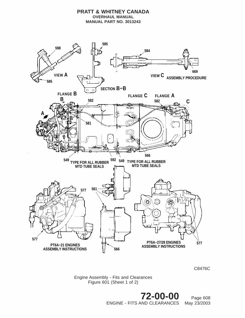
SECTION B−B
VIEW A VIEW C
BFLANGE CFLANGE AFLANGE
A
561577
577
566PT6A−21 ENGINES
ASSEMBLY INSTRUCTIONS
577PT6A−27/28 ENGINESASSEMBLY INSTRUCTIONS
566549592549
581
TYPE FOR ALL RUBBERMTD TUBE SEALS
TYPE FOR ALL RUBBERMTD TUBE SEALS
C582582B
B
584
669
ASSEMBLY PROCEDURE
585598
585
C8476C
Engine Assembly - Fits and ClearancesFigure 601 (Sheet 1 of 2)
PRATT & WHITNEY CANADAOVERHAUL MANUAL
MANUAL PART NO. 3013243
72-00-00 Page 608ENGINE - FITS AND CLEARANCES May 23/2003

VIEW A
A
184
200
199
186
184
961
962
PARTIAL REAR VIEW OF ENGINE
C8477A
Engine Assembly - Fits and ClearancesFigure 601 (Sheet 2)
PRATT & WHITNEY CANADAOVERHAUL MANUAL
MANUAL PART NO. 3013243
72-00-00 Page 609ENGINE - FITS AND CLEARANCES May 23/2003

TABLE 602, Torque and Stretch
REF NO. Description Torque Limits (lb.in.)
184 Plug (Pre-SB1217) 215 min. 240 min.
186 Nut, Mounting, Propeller Governor 125 min. 135 max.
199 Cover, Electrical Connection (Post-SB1217) 12 min. 16 max.
200 Chip Detector, Magnetic (Post-SB1217) 45 min. 55 max.
549 Nut Tighten until firm contact is madeplus 180 degrees.
561 Electrical Connectors Tighten fingertight plus 5 degrees.
566 Lead, Ignition Tighten fingertight plus 45 degrees.
577 Nut, Coupling 170 min. 200 max.
581 Nut, Self-locking 10 min. 15 min.
582 Casing Flexible Shaft 40 min. 60 max.
584 Nut, Plain 150 min. 250 max.
585 Nut, Castellated 20 min. 30 max.
592 Bolt Torque to 15-20 lb.in.then retorque to32-36 lb.in. without loosening.
598 Extension, Fuel Control Arm 25 min. 35 max.
669 Interconnect Control Cable - AssemblyProcedure
End of cable must extend beyondinspection hole.
961 Bolt Pre-SB1503,Post-SB1503
10 min.8 min.
15 max.12 min.
962 Bolt Pre-SB1503,Post-SB1503
8 min.8 min.
12 max.10 min.
PRATT & WHITNEY CANADAOVERHAUL MANUAL
MANUAL PART NO. 3013243
72-00-00 Page 610ENGINE - FITS AND CLEARANCES May 23/2003
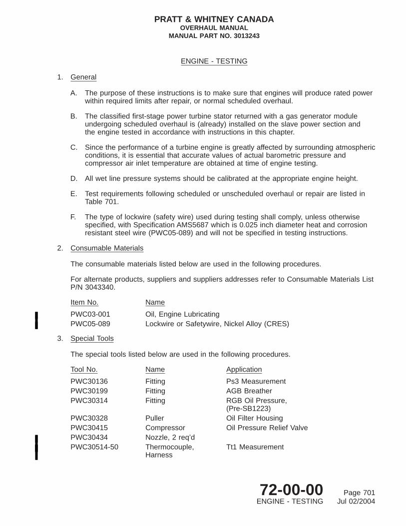
ENGINE - TESTING
1. General
A. The purpose of these instructions is to make sure that engines will produce rated powerwithin required limits after repair, or normal scheduled overhaul.
B. The classified first-stage power turbine stator returned with a gas generator moduleundergoing scheduled overhaul is (already) installed on the slave power section andthe engine tested in accordance with instructions in this chapter.
C. Since the performance of a turbine engine is greatly affected by surrounding atmosphericconditions, it is essential that accurate values of actual barometric pressure andcompressor air inlet temperature are obtained at time of engine testing.
D. All wet line pressure systems should be calibrated at the appropriate engine height.
E. Test requirements following scheduled or unscheduled overhaul or repair are listed inTable 701.
F. The type of lockwire (safety wire) used during testing shall comply, unless otherwisespecified, with Specification AMS5687 which is 0.025 inch diameter heat and corrosionresistant steel wire (PWC05-089) and will not be specified in testing instructions.
2. Consumable Materials
The consumable materials listed below are used in the following procedures.
For alternate products, suppliers and suppliers addresses refer to Consumable Materials ListP/N 3043340.
Item No. Name
PWC03-001 Oil, Engine LubricatingPWC05-089 Lockwire or Safetywire, Nickel Alloy (CRES)
3. Special Tools
The special tools listed below are used in the following procedures.
Tool No. Name Application
PWC30136 Fitting Ps3 MeasurementPWC30199 Fitting AGB BreatherPWC30314 Fitting RGB Oil Pressure,
(Pre-SB1223)PWC30328 Puller Oil Filter HousingPWC30415 Compressor Oil Pressure Relief ValvePWC30434 Nozzle, 2 req’dPWC30514-50 Thermocouple,
HarnessTt1 Measurement
PRATT & WHITNEY CANADAOVERHAUL MANUAL
MANUAL PART NO. 3013243
72-00-00 Page 701ENGINE - TESTING Jul 02/2004

Tool No. Name Application
PWC30556 PullerPWC30591 Bracket, Gearbox AGB MountPWC30814 Probe Oil and Fuel Temperature
measurementPWC31207-101 StarterPWC32080 Pad Engine MountPWC32081 Ring Engine MountPWC32082-100 Bracket Engine VibrationPWC32083 Ring Engine MountPWC32100-100 Propeller Engine Test, (PT6A-21)PWC32100-104 Propeller Engine Test, (PT6A-27/28)PWC32101-101 Governor Overspeed ControlPWC32105 Fitting RGB Oil Pressure,
(Post-SB1223)PWC32107 Fitting, 2 Req’d Oil Pressure MeasurementPWC32112 Fitting RGB Static PressurePWC32113 Fitting Oil Scavenge-to-coolerPWC32117 Lifting Eye Engine LiftPWC32246 Starter Dry SplinePWC32263 PlugPWC32291 Bracket AGB MountPWC32304-100 Bracket Engine Mount (starboard)PWC32305-100 Bracket Engine Mount (port)PWC32444 Plate, Adapter Starter Control UnitPWC32449 Thermocouple, 8
req’dTt7 Measurement
PWC34297 Fitting Test Cell Static PressurePWC34418 PullerPWC50931 Tachometer AGB Vibration SurveyPWC80503 Bracket AGB Vibration Survey
4. Fixtures, Equipment and Supplier Tools
The special tools listed below are used in the following procedures.
Name Remarks
Analyzer Tec Aces Model 1700, P/N 10-100-0464RAM Procedure Card Tec Aces PT6, P/N 11-100-0048Charge Converter Box Integrator Model 510-02, P/N 10-100-1502Cable 80 ft., P/N 10-320-0131Cable Tachometer Generator, 80 ft., P/N
10-320-0132Tachometer Matching box Model 516, P/N 10-100-1516
PRATT & WHITNEY CANADAOVERHAUL MANUAL
MANUAL PART NO. 3013243
72-00-00 Page 702ENGINE - TESTING Jul 02/2004

Name Remarks
Cable Microdot, 3 ft., P/N 75-200-0032Cable Interface, P/N 10-320-0133
5. Engine Test Equipment
A. General
(1) The equipment required for testing PT6A-21,-27 and -28 engines is listed in Paras.3. and 4. and are referred to in text.
(2) Engine testing shall be conducted on a suitably correlated test stand. Requirementsfor accomplishing overhaul test stand correlation may be obtained by contactingPratt & Whitney Canada, Customer Support Department. A condensed description oftest cell correlation procedures and requirements is also contained in the P&WCFacility Equipment and Planning Manual, P/N 3040878.
(3) For data reduction use program 30P10230 or PWC83020.
6. Engine Test Requirements
Engine test requirements for scheduled or unscheduled overhaul engines, gasgenerator/power section repairs are listed in Table 701.
TABLE 701, Test Requirements and Procedures
PARA. ENGINEGAS
GENERATORPOWER
SECTION
1. X X X
2. X X X
3. X X X
4. X X X
5. X X X
7. X X X
8. X X X
9. X X X
10.A. X X X
10.D. X X
10.E. X X
10.F. X X
10.G. X X
10.H. X X
10.I. X X
PRATT & WHITNEY CANADAOVERHAUL MANUAL
MANUAL PART NO. 3013243
72-00-00 Page 703ENGINE - TESTING Jul 02/2004

TABLE 701, Test Requirements and Procedures (Cont’d)
PARA. ENGINEGAS
GENERATORPOWER
SECTION
11.A. X X
11.B. X X
11.C. X X
11.D. X X
11.E. X X
12. X
13. X
14. X X
15. X X X
18. X X X
19. X
NOTE: The vibration survey requirement applies only to engines being testedfollowing overhaul or repair requiring balancing of the compressor rotorassembly.
7. Symbols
Symbols designated for various stations within the engine and working variables used inengine testing, are as follows. Capitalized symbols in parenthesis are used interchangeablywith those immediately adjoining, (e.g. Ng = NG) to provide similarity to appearance oncomputerized calculations.
Ng (NG) Gas Generator Speed, rpmNf (NF) Power Turbine Speed, rpmPam Ambient Barometric Pressure, in. HgPsgb Reduction Gearbox Static Pressure, PsigPsn Test Cell Static Pressure, in. H20δ P Engine Torquemeter Pressure minus Static Pressure, in. HgPs3 (PS3) Compressor Discharge Static Pressure, Psig‘‘G’’ Gravitational ConstantSFC Specific Fuel Consumption, WF/DELRTH + SHP/DELRTHSG Specific Gravity of Fuelshp (SHP) PT6A-21; Nf x del P divided by 5183
PT6A-27/-28 ; Nf x del P divided by 5272SG Base Turbine Meter Calibration StandardTf Fuel Temperature, °FTsg SG Fuel Sample Temperature, °FTtl Engine Inlet Temperature, °F
PRATT & WHITNEY CANADAOVERHAUL MANUAL
MANUAL PART NO. 3013243
72-00-00 Page 704ENGINE - TESTING Jul 02/2004

Tt5 (TT5) Interturbine Temperature, °F (°R)del T5 Untrimmed Tt5 minus Trimmed Tt5 value, °FT5D Calculated Interturbine Temperature, °F (°R)Tt7 (TT7) Engine Exhaust Nozzle Temperature °F (°R)Wf (WF) Fuel Flow, PPHin.Hg Inches of Mercuryin.H2O Inches of Water°F Degrees Fahrenheit°R Degrees Rankin, °F plus 459.688DEL (delta) Corrected Pam (in.Hg) divided by 29.921TH (theta) (Ttl plus 459.688) divided by 518.688RTH (root theta) Square root of thetaDELRTH (delta root theta) root theta multiplied by delta
8. Preparation for Test
A. Engine/Propeller Controls
(1) Because reverse power is not used during engine test, controls associated withreverse power feature, i.e., FCU interconnect rod and propeller reversing lever,are not installed until test is completed (Ref. Final Assembly).
(2) Push Beta valve fully in, and place reset lever in the fully forward position.
(3) Secure valve and lever in these positions with a suitable tension spring (5, Fig.702) attached to each of the components.
B. Install Test Equipment (Ref. Figs. 701 through 705)
(1) Install starter generator (PWC31207-101) or (PWC32246) with gasket on accessorygearbox housing studs and secure with four nuts and washers; torque 150 to170 lb.in.
(2) Install breather adapter fitting (PWC30199) on accessory gearbox and secure withtwo bolts; torque 32 to 36 lb.in.
(3) Install overspeed governor (PWC32101-101) with gasket on studs at left-hand sideof reduction gearbox and secure with four nuts and washers; torque 150 to170 lb.in.
(4) Install exhaust nozzles (PWC30434) on engine and secure each with six bolts andnuts; torque 65 to 75 lb.in.
(5) Install tachometer-generators:
(a) Install Nf tachometer-generator MS25038-04, with gasket on propeller reductiongearbox housing.
PRATT & WHITNEY CANADAOVERHAUL MANUAL
MANUAL PART NO. 3013243
72-00-00 Page 705ENGINE - TESTING Jul 02/2004

(b) Install Ng tachometer unit (PWC50931) with gasket on AGB housing.
NOTE: Ng tachometer unit (PWC50931) is for vibration survey only.
(c) Install Ng tachometer-generator MS25038-04 on tachometer unit.
(d) Secure with nuts and washers to housing, and torque 75 to 85 lb.in.
(6) Install main oil pressure fitting (PWC32107) on right-hand side of accessorygearbox housing. Torque fitting 375 to 425 lb.in.
(7) Install torquemeter pressure fitting (PWC32107) on right-hand side of reductiongearbox. Torque fitting 375 to 425 lb.in.
(8) Install torquemeter static fitting (PWC32112) on left-hand side of reduction gearbox.Secure fitting with two bolts; torque bolts 32 to 36 lb.in.
(9) Install reduction gearbox oil pressure fitting (PWC30314) PT6A-27/-28 enginesPre-SB1223 or (PWC32105) PT6A-27/-28 engines Post-SB1223 and all PT6A-21engines.
NOTE: Reduction gearbox oil pressure fitting need be installed only if reductiongearbox pressure reading is required during engine test.
(10) Install propeller oil pressure measurement adapter (PWC50391) on left-hand side ofreduction gearbox. Make sure hole of adapter is aligned to permit oil flow . Torquenuts 150 to 170 lb.in.
(11) Install accessory spur drive plug (PWC51336) inside gearshaft located in AGP padat the 10 o’clock position.
(12) Install 3 covers (PWC50380) on AGP pads. Torque bolts 75 to 85 lb.in.
(13) Install oil drain collector (PWC50384) on starter generator drain. Torque fitting 38 to42 lb.in.
(14) Install oil drain collectors (PWC50385), one on fuel pump drain and one onpropeller shaft drain. Torque fittings 38 to 42 lb.in.
(15) Install fuel dump collector (PWC50385) on fuel divider. Torque fittings 38 to 42 lb.in.
(16) Remove one fuel nozzle retaining bolt from gas generator case; install Ps3adapter (PWC30136) through flange of fuel nozzle into bolt hole. Torque adapter 25to 30 lb.in.
(17) Install oil inlet temperature thermocouple probe (PWC30814) in boss on right handside of engine accessory gearbox. Torque 65 to 75 lb.in.
(18) Assemble Tt1 thermocouple harness (PWC30514-50) to engine gas generator.Torque bolts 7 to 9 lb.in.
PRATT & WHITNEY CANADAOVERHAUL MANUAL
MANUAL PART NO. 3013243
72-00-00 Page 706ENGINE - TESTING Jul 02/2004

(19) On PT6A-27/-28 engines, install starting control adapter plate (PWC32444) onstarting control lever and secure with nuts, bolts and washers. Tighten nuts andtorque 32 to 36 lb.in.
(20) On some PT6A-28 engines, with an airframe-supplied flexible fuel hose, install aslave hose between oil-to-fuel heater and fuel pump. Torque hose coupling nuts450 to 500 lb.in. (Ref. Final Assembly-2).
(21) Remove two bolts, washers and nuts from flange A of propeller reduction gearboxat the 6 o’clock position. Install vibration bracket pickup assembly (PWC32082-100)at the rear of flange A and secure with two bolts, washers and nuts. Torque 36 to40 lb.in.
(22) Remove nuts from flange G at 3 o’clock position. Install AGB vibration bracket(PWC80503) at the rear of flange G. Secure with nuts and torque 32 to 36 lb.in.
NOTE: If interference is encountered when installing bracket and removal ofinterfering bracket is required, make sure the removed bracket is installedupon completion of vibration survey.
(23) Connect vibration survey equipment (Ref. Fig. 706).
(24) For a permanent record of vibration survey, attach printer and printer cable toACES Analyzer.
C. Removal from Assembly Stand and Install in Propeller Test Stand
(1) Attach hoist and lifting eye (PWC32117) to mount ring on assembly stand. Take upslack on hoist chain.
(2) Remove bolts and washers securing mount ring to adapters on stand (Ref. StorageInstructions).
(3) Make sure that mount pads (PWC32080) are installed on mount ring (PWC32081)and secured to gas generator case. Torque 365 to 390 lb.in. and 225 to 250 lb.in.respectively.
(4) Hoist engine, complete with mount ring, and secure to test stand with three boltsand nuts. Torque nuts 800 to 900 lb.in. and lock with cotterpins.
(5) Disconnect hoist and move it clear of test area.
D. Installation of Propeller
(1) Install propeller (PWC32100-100) or (PWC32100-104) with preformed packing onpropeller reduction gearbox shaft and secure with eight retaining bolts.
(2) Torque retaining bolts 660 to 730 lb.in and lockwire with single strand of lockwire.
PRATT & WHITNEY CANADAOVERHAUL MANUAL
MANUAL PART NO. 3013243
72-00-00 Page 707ENGINE - TESTING Jul 02/2004

12
4
5
9
8 10 7 6
3
C11321A
Test Cell Configuration - Left-hand Front ViewFigure 701
PRATT & WHITNEY CANADAOVERHAUL MANUAL
MANUAL PART NO. 3013243
72-00-00 Page 708ENGINE - TESTING Jul 02/2004

E. Remove from Assembly Stand and Install on Dynamometer Stand - (PWC32478)Mounting Arrangement (Ref. Fig. 707)
(1) Remove 22 bolts, washers and nuts from flange A of propeller reduction gearbox.Install engine mount ring (2) (PWC32083) in front of flange A and secure with 22slave bolts MS9518-20 and nuts (P/N3012675). Tighten nuts diametrically oppositein sequence and torque 36 to 40 lb.in.
(2) Remove nut (7), washer (6) and bolt (11) from bracket assembly (4) (PWC30591).Secure bracket (5) to accessory gearbox mount pad with three washers (8) andbolts (9). Tighten bolts, torque 140 lb.in., and lockwire.
(3) Attach hoist and lifting eye (PWC32117) to mount ring on assembly stand. Take upslack on hoist chain.
(4) Remove bolts and washers securing mount ring to adapters on stand (Ref. StorageInstructions).
(5) Lubricate preformed packing (19) (MS9388-328) and install on plug (18)(PWC32236), and insert plug into propeller shaft.
(6) Hoist engine and lower onto dynamometer stand.
(7) Secure engine rear support bracket (5) to struts (10) with bolt (11), washer (6) andnut (7); torque nut 500 lb.in.
(8) Secure engine mount ring (2) to left side mount (3) (PWC32305-100) and to rightside mount (1) (PWC32304-100) with bolts (12), spacers (13 and 14) and nuts (15).Torque nuts 4000 lb.in.
(9) Connect coupling shaft to propeller shaft flange and secure with eight bolts (21)and nuts (20); torque nuts 1500 lb.in.
F. Install Engine on Dynamometer Stand - (PWC70326) Mounting Arrangement
(1) Attach hoist and lifting bracket (PWC50373) to mount ring (PWC70330) on assemblystand. Take up slack on hoist chain.
Key to Figure 701
1. Propeller Governor2. Propeller Control3. Torque Static Pressure Fitting4. Mount Ring Bracket5. Mount Ring6. Overspeed Governor7. Reset Solenoid and Lead8. Magnetic Chip Detector Lead9. Torquemeter Static Line
10. Vibration Bracket Assembly
PRATT & WHITNEY CANADAOVERHAUL MANUAL
MANUAL PART NO. 3013243
72-00-00 Page 709ENGINE - TESTING Jul 02/2004

9 7
6
1 2 38
4
5
C8114A
Test Cell Configuration - Right-hand Front ViewFigure 702
PRATT & WHITNEY CANADAOVERHAUL MANUAL
MANUAL PART NO. 3013243
72-00-00 Page 710ENGINE - TESTING Jul 02/2004

(2) Remove bolts and washers securing engine mount ring to adapters on assemblystand (Ref. Storage Instructions).
(3) Make sure that mount pads are installed to mount ring (PWC70330) and secure togas generator case. Torque 350 to 400 lb. in. and 225 to 300 lb. in. respectively.
(4) Install propeller shaft plug (PWC50574).
(5) Hoist engine, complete with mount ring and secure to mount ring adapter(PWC70327). Torque bolts to 750 lb. in. and lockwire.
(6) Mate engine propeller shaft to adapter flange (PWC70329-01). Torque bolts to 600to 650 lb. in. and lockwire.
G. Connect Test Stand Controls
(1) Connect test stand power control to FCU power control lever.
(2) On PT6A-27/-28 engines connect test stand condition (start control) lever to startingcontrol adapter plate (PWC32444) installed on engine starting control lever.
(3) Connect test stand propeller speed control to speed control lever of enginepropeller governor.
(4) Check for full and free movement of controls. Adjust test stand linkage asnecessary.
H. Connect Test Cell Plumbing and Instrumentation
(1) For location of test cell connections, refer to Figures 701 through 705 and Para. B.,preceding.
(2) Install oil scavenge-to-cooler elbow (PWC32113) between engine scavenge pumpoutlet and oil cooler inlet line.
(3) Connect test cell oil cooler return oil line at 12 o’clock position on compressor inletcase. Torque 900 to 1000 lb.in.
Key to Figure 702
1. Tt7 Thermocouple and Lead2. Ps3 Sensing Fitting and Line3. Tt5 Trim Lead Terminals4. Torque Pressure Fitting and Line5. Tension Spring6. Nf Tachometer-generator and Lead7. Propeller Shaft Seal Drain8. Py Line9. Exhaust Nozzle
PRATT & WHITNEY CANADAOVERHAUL MANUAL
MANUAL PART NO. 3013243
72-00-00 Page 711ENGINE - TESTING Jul 02/2004

1110
9
8 6 7
5
4
1 2
3
C8113
Test Cell Configuration - Left-hand Rear ViewFigure 703
PRATT & WHITNEY CANADAOVERHAUL MANUAL
MANUAL PART NO. 3013243
72-00-00 Page 712ENGINE - TESTING Jul 02/2004

(4) Connect engine breather tube to breather adapter on accessory gearbox usingworm-drive hose clamp.
(5) Connect fuel inlet line (incorporating fuel inlet thermocouple) (PWC30814) tooil-to-fuel heater. Torque 450 to 500 lb.in.
(6) Connect engine ignition leads to ignition exciter (or current regulator). Tightenfingertight plus 45 degrees.
(7) Connect ignition input lead.
(8) Connect starter cables.
(9) Connect drain lines to the following:
Fuel pumpPropeller shaft sealStarter-generator seal cavityFlow divider and dump valve (PT6A-21 engines)Starting Control (PT6A-27/-28 engines)Gas generator case
CAUTION: SECURE ALL INSTRUMENTATION LINES AND LEADS TO PREVENTCHAFING OR CONTACT WITH HOT PARTS OF ENGINE.
(10) Connect the following:
NOTE: Connect all electrical lead connectors fingertight plus 45 degrees.
(a) Torque pressure line.
(b) Torque static line.
(c) Main oil pressure sensing line.
Key to Figure 703
1. Ignition Input Lead2. Oil Return line from Cooler3. Starter Cable Connector4. Starter5. Starter Cavity Drain6. Scavenge Oil-to-Cooler Elbow7. Scavenge Oil Pressure Line8. Scavenge Oil Temperature Lead9. Ignition Lead
10. Ignition Exciter11. Tt1 Harness
PRATT & WHITNEY CANADAOVERHAUL MANUAL
MANUAL PART NO. 3013243
72-00-00 Page 713ENGINE - TESTING Jul 02/2004

1 2 3
7
6
5
4
C8112
Test Cell Configuration - Right-hand Rear ViewFigure 704
PT6A-21
PRATT & WHITNEY CANADAOVERHAUL MANUAL
MANUAL PART NO. 3013243
72-00-00 Page 714ENGINE - TESTING Jul 02/2004

(d) Main oil inlet temperature thermocouple lead.
(e) Scavenge oil pressure sensing line.
(f) Scavenge oil temperature thermocouple lead.
NOTE: Pressure sensing line and temperature thermocouple lead, areconnected to oil pressure and temperature fittings incorporated in oilscavenge-to-cooler elbow (Ref. step (2)).
(g) Overspeed governor reset solenoid lead.
(h) Reduction gearbox oil pressure sensing line, if required (Ref. Para. B. (9)).
(i) Tt1 and Tt7 harness leads.
(j) Tt5 cell leads to terminals on gas generator case.
(k) Ng and Nf tachometer-generator lead.
(l) Magnetic chip detector lead.
(m) Vibration pickup lead.
(11) Remove engine oil filter element and replace with slave-filter element of identicalpart number (Ref. Disassembly).
(12) Make sure filter, Tt7 measurement thermocouple (PWC32449), and test cell staticpressure probe (PWC34297) are correctly installed.
I. Fill Engine Oil Tank
(1) Unlock filler cap on accessory gearbox housing and withdraw dipstick from fillertube.
CAUTION: DO NOT MIX DIFFERENT BRANDS, VISCOSITIES OR SPECIFICATIONSOF OIL AS THEIR DIFFERENT CHEMICAL STRUCTURE CAN MAKETHEM INCOMPATIBLE.
(2) Add oil (PWC03-001) to tank until level is at MAX. COLD mark on dipstick.
(3) Replace filler cap and dipstick and lock securely.
Key to Figure 704
1. Fuel Inlet Connection and Line2. Breather Fitting and hose3. Power Control4. Main Oil Pressure Fitting and Line5. Oil Temperature Fitting and Thermocouple6. Fuel Pump Drain7. Ng Tachometer-generator and Lead
PRATT & WHITNEY CANADAOVERHAUL MANUAL
MANUAL PART NO. 3013243
72-00-00 Page 715ENGINE - TESTING Jul 02/2004

9
12 3 4
78
6 10 5
C8111B
Test Cell Configuration - Right-hand Rear ViewFigure 705
PT6A-27/-28
PRATT & WHITNEY CANADAOVERHAUL MANUAL
MANUAL PART NO. 3013243
72-00-00 Page 716ENGINE - TESTING Jul 02/2004

J. Depreserve Fuel System
CAUTION: FUEL SYSTEMS PRESERVED WITH OIL FOR STORAGE PURPOSES MUSTBE PURGED PRIOR TO MOTORING CYCLE.
(1) On PT6A-21 engines disconnect fuel line at flow divider and dump valve inlet fordrainage into suitable container.
(2) On PT6A-27/-28 engines disconnect fuel lines at outlet side of starting flow controlvalve. Cap the bypass, dump and No.1 manifold outlets, allowing drainage fromNo.2 manifold outlet into a suitable container.
(3) Open test cell fuel valve and switch fuel pump ON.
(4) Ensure ignition switch is OFF.
(5) Place propeller control lever at FEATHER. Power control lever at IDLE. OnPT6A-27/-28 engines place start control lever at RUN.
CAUTION: OBSERVE STARTER MOTOR OPERATING LIMITS. REFER TOSTARTER MANUFACTURER’S MANUAL.
(6) Motor engine until clean fuel flows from open line.
(7) Position power control lever to FUEL CUT-OFF, switch fuel supply pump OFF andclose test cell fuel valve.
(8) Reconnect fuel line to flow divider and dump valve and secure line attachmentpoints.
(9) On PT6A-27/-28 engines remove caps from the bypass, dump and No.1 manifoldoutlets and reconnect all fuel lines to starting control unit.
Key to Figure 705
1. Main Oil Pressure Fitting and Line2. Breather Tube3. Power Control4. Pneumatic Tubes Heater Connection5. Oil Temperature Fitting and Thermocouple6. Starting Control7. Fuel Pump Drain8. Ng Tachometer-generator and Lead9. Fuel Connection and Line
10. Starting Control Adapter Plate
PRATT & WHITNEY CANADAOVERHAUL MANUAL
MANUAL PART NO. 3013243
72-00-00 Page 717ENGINE - TESTING Jul 02/2004

TO TEST CELLSPEED SYST.
1
2
3
4 5 6
7
8
91011
12
13
C39205
AGB Vibration Survey - ACES AnalyzerFigure 706
PRATT & WHITNEY CANADAOVERHAUL MANUAL
MANUAL PART NO. 3013243
72-00-00 Page 718ENGINE - TESTING Jul 02/2004

9. Engine Motoring, Starting and Shutdown
A. Prestart Checks
(1) Make sure that the engine test installation is clear of all loose nuts, bolts, tools orother foreign objects.
(2) Remove all loose objects from test cell floor.
(3) Recheck engine and propeller controls for full travel.
B. Wet Motoring Run
WARNING: IF FIRE CONDITION OCCURS WITHIN ENGINE DURING MOTORINGRUNS, IMMEDIATELY CLOSE TEST CELL FUEL SYSTEM SUPPLY ANDCONTINUE MOTORING ENGINE.
(1) Position controls as follows:
(a) Ignition switch OFF.
(b) Test cell fuel valve OPEN.
(c) Fuel supply pump switch ON. Confirm fuel inlet pressure is not less than 5psig.
(d) Propeller control lever at FEATHER.
(e) Power control lever at fuel CUT-OFF (PT6A-21 engines).
(f) Power control lever at IDLE (PT6A-27/-28 engines).
(g) Start control lever at CUT-OFF (PT6A-27/-28 engines).
Key to Figure 706
1. Tachometer Unit (PWC50931)2. Tachometer-Generator3. Accelerometer Bracket (PWC80503)4. Microdot Cable (75-200-0031)5. Charge Convertor (10-100-510-2)6. Extension Cable (10-320-0031)7. Tachometer Matching Box (10-100-1516)8. Interface Cable (10-320-0133)9. PT6A RAM Procedure Card (11-100-0048)
10. ACES Analyzer Model 1700 (10-100-0464)11. Tachometer-Generator Cable (10-320-0132)12. Printer13. Printer Cable
PRATT & WHITNEY CANADAOVERHAUL MANUAL
MANUAL PART NO. 3013243
72-00-00 Page 719ENGINE - TESTING Jul 02/2004

DETAIL DDETAIL C
DETAIL B
B
B
D
DETAIL A
A
C
10
9
8
11 5
6
720
1918
PROPELLERSHAFT FLANGE
COUPLING SHAFT(REF.)
21
17
2
16
AFLANGE
15 14
1312
23
(TYPICAL)
4
1
2
C8890
Engine Installation in Dynamometer Test Stand - (PWC32478) Mounting ArrangementFigure 707
PRATT & WHITNEY CANADAOVERHAUL MANUAL
MANUAL PART NO. 3013243
72-00-00 Page 720ENGINE - TESTING Jul 02/2004

CAUTION: ALLOW SUFFICIENT STARTER COOLING PERIOD BETWEENMOTORING CYCLES AND ENGINE START; REFER TO STARTERMANUFACTURERS LIMITS AND RECOMMENDATIONS.
(2) Place starter switch ON. Motor engine with starter until a steady state gasgenerator speed of approximately 7000 Ng and oil pressure of 30 psi (minimum) isattained.
(3) Advance power control lever fully (PT6A-21 engines) or start control lever to RUN(PT6A-27/-28 engines), for maximum of 10 seconds.
(4) Record fuel flow rate which must be 70 to 100 pph before start attempt is made. Ifnot within this range, reject the fuel control unit.
(5) Retard power control lever (PT6A-21 engines), or start control lever (PT6A-27/-28engines) to CUT-OFF.
(6) Place starter switch OFF.
(7) During engine rundown, check operation of dump valve and gas generator casedrain valves. Listen for unusual noises such as scraping or rubbing sounds. If anysuch noise is heard, determine location and possible cause; rectify (Ref. LightOverhaul).
Key to Figure 707
1. Engine Mount (Right Side)2. Engine Mount Ring3. Engine Mount (Left Side)4. Bracket Assembly5. Bracket6. Washer7. Nut8. Washer9. Bolt
10. Strut11. Bolt12. Bolt13. Spacer14. Spacer15. Nut16. Nut17. Bolt (typical)18. Plug19. Preformed Packing20. Nut21. Bolt
PRATT & WHITNEY CANADAOVERHAUL MANUAL
MANUAL PART NO. 3013243
72-00-00 Page 721ENGINE - TESTING Jul 02/2004

(8) Note and record engine rundown time (minimum 20 seconds).
(9) Close fuel valve and place fuel pump switch OFF.
(10) Check for fuel and oil leakage. Rectify as necessary.
(11) Perform dry motoring run (Ref. Subpara. C.).
C. Dry Motoring Run
NOTE: This procedure is used to remove internally trapped fuel and fuel vapor, or ifthere is evidence of fire within the engine. Air passing through the engineserves to purge fuel/fuel vapor from the combustion section, power turbine andexhaust system.
(1) Ignition switch OFF.
(2) Test cell fuel valve OPEN.
(3) Fuel supply switch ON.
(4) Propeller control lever at FEATHER.
(5) Start control lever (PT6A-27/-28 engines) or power control lever (PT6A-21 engines)at CUT-OFF.
(6) Place starter switch ON and motor engine for maximum of 10 seconds to expel fueland fuel vapors. Switch starter OFF; when engine stops rotating, close fuel valveand place fuel supply pump switch to OFF.
(7) Check engine oil level (Ref. Para. 8.) and replenish tank to MAX. COLD level.
D. Engine Starting (PT6A-21)
CAUTION: ALLOW SUFFICIENT STARTER COOLING PERIOD BETWEEN MOTORINGCYCLES AND ENGINE STARTS; REFER TO STARTER MANUFACTURERSLIMITS AND RECOMMENDATIONS.
(1) Position controls as follows:
(a) Ignition switch OFF.
(b) Starter switch OFF.
(c) Power control lever at fuel CUT-OFF.
(d) Propeller control lever at FEATHER.
(e) Test cell fuel valve OPEN.
(f) Fuel supply switch ON. Confirm that fuel inlet pressure is not less than 5 psig.
PRATT & WHITNEY CANADAOVERHAUL MANUAL
MANUAL PART NO. 3013243
72-00-00 Page 722ENGINE - TESTING Jul 02/2004

CAUTION: IF Tt5 OBSERVED EXCEEDS 1350°F OR CONTINUOUS FLAME ISSUESFROM EXHAUST, SHUT OFF POWER CONTROL LEVER IMMEDIATELY.DO NOT ATTEMPT TO RELIGHT ON RUNDOWN; WAIT UNTIL ENGINECOMES TO REST, THEN IMPLEMENT DRY MOTORING CYCLE TO COOLENGINE.
(2) Simultaneously, place starter and ignition switches to ON and, when Ng stabilizesat a speed above 4500 rpm, advance power control lever to RUN.
NOTE: On glow plug ignition systems allow Ng to stabilize at a speed above 4500rpm for five seconds.
(3) Observe that engine lights, then return ignition and starter switches to OFF afterengine has accelerated smoothly to idle speed, 19750 ± 500 rpm.
E. Engine Starting (PT6A-27/-28)
CAUTION: ALLOW SUFFICIENT STARTER COOLING PERIOD BETWEEN MOTORINGCYCLES AND ENGINE STARTS; REFER TO STARTER MANUFACTURERSLIMITS AND RECOMMENDATIONS.
(1) Position controls as follows:
(a) Ignition switch OFF.
(b) Starter switch OFF.
(c) Power control lever at GI.
(d) Propeller control lever at FEATHER.
(e) Start control lever at CUT-OFF.
(f) Test cell fuel valve OPEN.
(g) Fuel supply switch ON. Fuel inlet pressure is 5 psig minimum.
CAUTION: IF Tt5 OBSERVED EXCEEDS 1350°F (PT6A-10) OR 1400° F (PT6A-15AG)OR CONTINUOUS FLAME ISSUES FROM EXHAUST, SHUT OFF STARTCONTROL LEVER IMMEDIATELY. DO NOT ATTEMPT TO RELIGHTON RUNDOWN; WAIT UNTIL THE ENGINE COMES TO REST, THENIMPLEMENT A DRY MOTORING CYCLE TO COOL THE ENGINE.
(2) Simultaneously, place starter and ignition switches to ON and, when Ng stabilizesat a speed above 4500 rpm, advance power control lever to RUN.
NOTE: On glow plug ignition systems allow Ng to stabilize at a speed above 4500rpm for five seconds.
(3) Observe that engine lights, then return ignition and starter switches to OFF afterengine has accelerated smoothly to idle speed.
PRATT & WHITNEY CANADAOVERHAUL MANUAL
MANUAL PART NO. 3013243
72-00-00 Page 723ENGINE - TESTING Jul 02/2004

F. Unsatisfactory Start
NOTE: If one or more of the following conditions occur during engine starting, shutdown engine immediately; anticipatory action is to be taken, wheneverpossible, to prevent engine temperature limitations being exceeded.
(1) Engine fails to light up within 10 seconds of advancing power control lever tominimum idling speed.
(2) False or hung start: After light-up, engine fails to reach idling speed.
(3) Hot start: Tt5 exceeds starting temperature limits. This condition may be precededby false or hung start.
G. Shutdown
WARNING: IF A FIRE OCCURS IN THE ENGINE AFTER SHUTDOWN, DO A DRYMOTORING RUN IMMEDIATELY (REF. SUBPARA. C.).
(1) Allow engine to run at ground idle for at least one minute to stabilize at minimumrunning temperatures.
(2) Move propeller control lever to FEATHER.
(3) Move start control lever (PT6A-27/-28 engines) or power control lever (PT6A-21engines) to CUT-OFF. Note rundown time and record.
(4) Shut off test cell fuel supply and switch fuel supply OFF.
10. Test Procedure
A. Points to be Understood before Testing
NOTE: Refer to Subpara. B. for supplementary limitations.
(1) All operating limits quoted in Table 702 are observed during all phases of testprocedure.
(2) Test cell instrument readings taken during test run are recorded in engine test log(Ref. Fig. 708).
(3) On engines tested in a dynamometer test facility propeller feathered is defined as4500 Nf ± 500, and maximum fine pitch is defined as 12500 Nf ± 500.
NOTE: These definitions relate only to minimum idling speed settings.
TABLE 702, Engine Test Operating Conditions
MAXIMUM OPERATINGCONDITION PT6A-21 PT6A-27/-28
Ng (rpm)
Steady State 38,100 38,100
PRATT & WHITNEY CANADAOVERHAUL MANUAL
MANUAL PART NO. 3013243
72-00-00 Page 724ENGINE - TESTING Jul 02/2004

TABLE 702, Engine Test Operating Conditions (Cont’d)
MAXIMUM OPERATINGCONDITION PT6A-21 PT6A-27/-28
Accelera-tion*
38,500 38,500
NOTE: Rundown time on the compressor from ground-idle must not be less thantwenty seconds.
Nf (rpm)
Steady State 34,200 34,200
Accelera-tion*
36,300 36,300
Tt5 (°F)
Start 1350 1440
SteadyState,Trimmed
1283 1380
SteadyState,Untrimmed
1325 1400
del P (in.Hg)
Steady State 92 125
Accelera-tion*
94 127
* Two second time limit
B. Supplementary Limitations (Ref. Table 702)
(1) Fuel pressure at the engine inlet shall be 5 to 20 psig at all times includingtransient conditions.
(2) Oil temperature limit for all running with exception of transients shall be 140° to160°F.
(3) Scavenge oil back pressure at the engine outlet shall be 20 psig min. to 50 psigmax.
(4) Maximum permitted difference between individual inlet temperature thermocoupleindications is 8°F.
(5) Maximum permitted difference between average Tt7 thermocouple readingsbetween each exhaust nozzle assembly is 60°F and between thermocouples withina given nozzle is 100°F.
(6) Maximum torque at idle is 10 in.Hg. Engine torquemeter system shall be purgedprior to oil level check at acceptance calibration.
PRATT & WHITNEY CANADAOVERHAUL MANUAL
MANUAL PART NO. 3013243
72-00-00 Page 725ENGINE - TESTING Jul 02/2004

(7) Maximum acceptance limit for vibration shall not exceed 100 ‘‘G’’.
(8) Steady State stability limits as follows:
Ng Speed ± 50 rpm100% NgSpeed
= 37468 rpm
Nf Speed ± 100 rpm100% NfSpeed
= 33000 rpm (PT6A-21 Engines)
100% NfSpeed
= 33235 rpm (PT6A-27/28 Engines)
δP torque ± 1.5 in. HgTt5temperature
± 5°F
C. Run-in Procedure
NOTE: This procedure is to be done after scheduled or unscheduled overhaul/repairhas been completed and before all other test running.
(1) Do a wet motoring run followed with a dry motoring run (Ref. Para. 9. preceding).
(2) With propeller lever in feather position, start engine and run at ground-idle 19750 ±500 rpm Ng (propeller testing) or rotate dynamometer controller to obtain 5000 rpmNf or maximum available (dynamometer testing) for 5 minutes.
(3) Record Ng, Nf, Tt1, Tt5, del P, oil pressures and oil temperatures.
(4) Unfeather propeller and run at ground-idle with propeller in fine pitch (propellertesting) or rotate dynamometer controller to obtain 15000 rpm Nf or maximumavailable (dynamometer testing) for 5 minutes.
(5) Record Ng, Nf, Tt1, Tt5, del P, oil pressure and oil temperatures.
(6) Carry out two feathering cycles to check propeller governor and propeller systems.
D. Preliminary Checks
CAUTION: DO NOT EXCEED OPERATING LIMITS (REF. TABLE 702).
(1) Obtain an accurate setting of NF/RTH = 33000 rpm as follows:
NOTE: To obtain physical Nf, multiply 33000 by RTH.
CAUTION: DO NOT EXCEED 34200 Nf.
(a) With propeller control lever in the maximum rpm position, move power controllever slowly until Nf ceases to increase (propeller testing) or rotate dynamometercontroller until a sudden drop occurs in propeller oil pressure. Check that33000 ± 300 rpm Nf is obtained.
PRATT & WHITNEY CANADAOVERHAUL MANUAL
MANUAL PART NO. 3013243
72-00-00 Page 726ENGINE - TESTING Jul 02/2004

(b) If required Nf cannot be obtained, shut down engine and reset propellermaximum speed adjustment (Ref. Para. 11.B. following).
(2) Perform two feathering operations:
(a) With propeller control lever in the maximum position, set power control lever toobtain 30000 ± 1000 rpm Ng and lock stop on console. Move propeller controllever to feather position until lever is hard against stop (propeller testing).
(b) Record Ng before and after feather condition. A change of more than 100 rpmNg requires CSU to be changed.
(c) With propeller control lever in the maximum position, set power control lever toobtain 24000 ± 500 rpm Ng and rotate dynamometer controller to obtain 5000± 500 rpm Nf and lock stop on console. Retard propeller control lever frommaximum to feather stop position (dynamometer testing).
(d) Record Ng, Nf and propeller oil pressure.
(e) A change of more than 100 rpm Ng requires CSU to be changed. Propeller oilpressure should be less than 20 psig.
(f) Unfeather propeller and unlock stop on console.
(3) With oil temperature controlled at 140° to 160°F, make sure oil pressure is 85 to 95psig at 27000 Ng and above, and not less than 40 psig at ground-idle. If necessary,adjust as follows:
(a) Shut down engine (Ref. Para. 9.).
(b) Drain engine oil (Ref. Disassembly).
(c) Remove oil filter cover, using puller (PWC30556) extract filter element. Removefilter housing from inlet case (Ref. Disassembly) with puller (PWC30328).
(d) With compressor tool (PWC30415), remove retaining ring and relief valve frominlet case.
(e) Disassemble relief valve (Ref. 72-60-00).
(f) Add or remove adjusting spacers, as required (Ref. 72-60-00).
(g) Install relief valve through aperture in air inlet case into oil pressure pumphousing and using compressor tool (PWC30415) secure relief valve withretaining ring (Ref. Final Assembly).
(h) Install check valve assembly, oil filter element and cover (Ref. Final Assembly).
(i) Refill oil tank (Ref. Para. 8.).
(j) Start engine, recheck oil pressure and record.
PRATT & WHITNEY CANADAOVERHAUL MANUAL
MANUAL PART NO. 3013243
72-00-00 Page 727ENGINE - TESTING Jul 02/2004

E. AGB Vibration Survey
NOTE: 1. The vibration survey requirement applies only to engines being testedfollowing overhaul or repair requiring balancing of the compressor rotorassembly.
NOTE: 2. Do the vibration survey using the following procedures and the ACESOperator’s Manual. Personnel must be familiar with the Analyzer prior toperforming these operations.
(1) Install the ACES PT6 RAM procedure card (11-100-0048) in the analyzer. Selectthe analyzer power on, and load the procedure.
NOTE: Ensure battery charge indication is greater than 40 percent.
(2) Select ‘‘PT6A 1ENg Survey Engine Model’’ from the operation options menu.
(3) Use cursor keys to select PT6A engine model.
NOTE: Vibration survey is common for all PT6A engines, engine model selectionis for survey records (hardcopy).
(4) Select ‘‘Perform Engine Survey’’ from the main menu.
(5) Start engine (Ref. Para. 9.). Let engine stabilize and oil temperature to reach aminimum of 51°C (125°F).
(6) Select ‘‘Start Engine Survey’’ from the menu on the analyzer.
(7) Enter the engine serial number.
(8) Select the Vibration Sensor as a BK4505/TEC, and set the input range to 1.0.
(9) Acceleration Survey
(a) Select ‘‘Acceleration Survey’’ from the menu on the analyzer.
CAUTION: DO NOT EXCEED ENGINE OPERATING LIMITS. ENGINEOPERATING LIMITS SUPERSEDE ANY INSTRUCTION IN ACESANALYZER PROCEDURE.
(b) Set power control lever to GROUND-IDLE.
(c) Set propeller control lever to 33000 rpm Nf.
(d) Ng Sweep:
1 Press ‘‘Enter’’ on the analyzer to start recording.
2 Accelerate slowly at a rate of 5000 rpm/min from GROUND-IDLE to maxavailable Ng without exceeding any operating limits. Reduce toGROUND-IDLE.
PRATT & WHITNEY CANADAOVERHAUL MANUAL
MANUAL PART NO. 3013243
72-00-00 Page 728ENGINE - TESTING Jul 02/2004

(e) Press ‘‘Enter’’ on the analyzer to stop recording.
(10) When survey is completed, review and record peak amplitude by using the cursorkeys to locate the peak.
(a) To magnify or reduce vertical scale use vertical arrow keys tagged ‘‘Point.’’
(b) To magnify horizontal scale between point ‘‘A’’ and ‘‘B’’, select point ‘‘A’’ withcursor and press ‘‘MARK.’’ Select Point ‘‘B’’ with cursor and press ‘‘EXP.’’
(c) To return to original screen, select Point ‘‘A’’ and press ‘‘MARK,’’ and thenselect Point ‘‘B’’ and press ‘‘CLR.’’
(d) For a hard copy, press and hold the ‘‘0’’ key on the ACES Analyzer. The printerwill copy the displayed screen.
(e) Exit to the main menu on the ACES Analyzer.
(11) Shutdown Survey
(a) Perform steps (1) through (8) above.
(b) Select ‘‘Shutdown Survey’’ from the menu on the ACES Analyzer.
(c) Press ‘‘Enter’’ on the ACES Analyzer to start recording. Shut down engine fromidle.
(d) End vibration survey after engine reaches 0 rpm and a sync error appears onthe ACES Analyzer; then press ‘‘Enter’’ on the ACES Analyzer to stoprecording.
(e) Perform step (10) above.
(12) 1 ENg Vibration Acceptance Limit:
(a) From the plots produced above, ensure that 1ENg vibration level does notexceed the following limits:
GROUND-IDLE to max Ng ; 0.5 cm/secShutdown from GROUND-IDLE to 5000 rpm Ng; 0.5 cm/sec
F. Acceleration and Bodie Checks
(1) If engine response is sluggish, or acceleration rate is too slow, check P3 and fuelsystem pneumatic control tubes and connectors for leakage or obstruction, beforeany fuel control adjustments are made (Ref. Troubleshooting).
(2) Position power control lever maximum stop on console to limit torque to 86.3 in.Hg.(PT6A-21 engines) or 108.6 in.Hg. (PT6A-27/-28 engines) or maximum obtainable,without exceeding engine operating limits (Ref. Table 702). Lock stop on console.
(3) Set propeller control lever or rotate dynamometer controller to give 32000 rpm Nf.
PRATT & WHITNEY CANADAOVERHAUL MANUAL
MANUAL PART NO. 3013243
72-00-00 Page 729ENGINE - TESTING Jul 02/2004

(4) Record Ng, Nf, Tt1 and δP.
(5) Decrease power control lever to flight-idle 23600 ± 100 rpm Ng.
(6) Slam accelerate from flight-idle to T.O. timed to 97.5% of take-off Ng. Slamdecelerate to ground-idle (19750 ± 500).
NOTE: The time taken to move power control lever in checks (5) through (6) mustnot exceed 1.0 second, engine should respond smoothly during accelerationand deceleration.
(7) Acceleration time must fall within range specified (Ref. Fig. 709).
CAUTION: MAXIMUM ADJUSTMENT ON FCU ACCELERATION DOME TO MEETACCELERATION TIME IS THREE CLICKS CLOCKWISE ORCOUNTERCLOCKWISE.
(8) If necessary, adjust engine acceleration by rotating FCU acceleration dome (Ref.Fig. 715 or 716 as applicable) one detent at a time, using minimum number toobtain satisfactory acceleration. Rotate dome clockwise to decrease (fasteracceleration) and counterclockwise to increase (slower acceleration) accelerationtime.
(9) Bodie check:
(a) Rotate FCU acceleration dome three detents clockwise to increase fuel flow.
(b) Run engine for not less than one minute at maximum stop (Ref. step (2)preceding) to achieve stabilization; slam decelerate to 32000 Ng, then withoutdwelling at lower speed, slam accelerate to maximum stop. Repeat to26000 Ng; again slam to maximum stop. Reduce Ng to GI.
NOTE: For sequential bodie checks, dwell time at each power setting shouldbe minimum required for engine to stabilize.
(c) If engine is stall and surge free on completion of bodie checks, reset accelerationdome to original position (three detents counterclockwise).
(d) If engine stall or surge is experienced during checks, rotate acceleration domeone detent counterclockwise and repeat bodie check.
(e) If surge is still evident, check compressor bleed valve operation.
(f) If bleed valve is functioning correctly, the dome may be reset a further twodetents, a bodie check being implemented after each detent adjustment.
(g) When surge is eliminated, reset dome three detents counter clockwise fromsurge-free setting.
(h) After satisfactory completion of bodie check following adjustment, recheckacceleration time (Ref. steps (5) and (6) preceding).
PRATT & WHITNEY CANADAOVERHAUL MANUAL
MANUAL PART NO. 3013243
72-00-00 Page 730ENGINE - TESTING Jul 02/2004

(10) Following acceptable acceleration and bodie checks, if scribe marks do not align,remove seal and lockwire on FCU acceleration dome. Holding adjusting screw withan Allen wrench, loosen adjuster locknut. Turn dome to re-align scribe marks,then tighten locknut, lockwire and seal. lockwire dome tab.
(11) Reset propeller control lever stop on console to permit 33000 Nf selection.
G. Tt5 Trim Determination
(1) Start engine, and advance power control and propeller control levers (propellertesting) or rotate dynamometer controller until engine is operating at observedpower of 550 ± 10 SHP/DELRTH (PT6A-21 engines) or 680 ± 10 SHP/DELRTH(PT6A-27/-28 engines) or maximum power obtainable without exceeding engineoperating limits (Ref. Table 702) and at an Nf/RTH equal to 33000 rpm but notto exceed 34200 rpm (observed).
(2) Run engine for 5 minutes at this power setting to obtain stabilization. Annotate logsheet; Tt5 Trim Determination and record set of readings.
NfNgPam or BaroPsn or P1000Ps3δPSGTfTsgTt1Tt5Tt7Wf
(3) Determine trim value from readings in step (2), preceding. Process Data withProgram 30P10230 or PWC83020.
(a) With results obtained in step (3) preceding, calculate trim to suppress TT5/THto a value T5D/TH - 60° ± 10 F° (PT6A-21/-27/-28 engines) or T5D/TH - 65° ±5 F° (PT6A-28 Piper engines only).
Tt5 Trim Determination (example):
TT5/TH = 1753°R
T5D/TH = 1733°R
T5D/TH - 60° = 1733 - 60 = 1673°R
del T5/TH trim = 80°
PRATT & WHITNEY CANADAOVERHAUL MANUAL
MANUAL PART NO. 3013243
72-00-00 Page 731ENGINE - TESTING Jul 02/2004

(b) Record δ T5 value on log sheet in F° and C°
δ T5/TH C° =δ T5/TH °F
1.8
(c) Trim value obtained in step (a) preceding is for a 59°F day. To trim engine, thisvalue should be denormalized as follows:
1 del T5/TH x TH = del T5.
(4) Select appropriate class of trim harness (P/N 3013604 or P/N 3031417) (Ref. Table703).
(5) Install selected trim harness (Ref. Final Assembly), and record class in log sheet.
(6) Start engine and run at take-off power (Ref. step (1), preceding).
(7) After allowing for stabilization of readings, make sure that selected trim reduces Tt5by the required value. If you are using program PWC83020, check the T5 trimcheck box and the output screen will state if the trim is good or not. Should it benecessary, install another class of trim and recheck.
(8) Annotate log sheet; Tt5 TRIM CHECK POINT TRIMMED in remarks column.
TABLE 703, Trim Harness Classification
3031417 ± 5% @ 70°F Approx. Ohms Approx. Range F° 3013604
Class 10 3.75 to 3.95 -208 to -200 -
Class 11 3.95 to 4.20 -200 to -190 -
Class 12 4.20 to 4.45 -190 to -180 -
Class 13 4.45 to 4.75 -180 to -171 -
Class 14 4.75 to 5.10 -171 to -161 -
Class 15 5.10 to 5.50 -161 to -151 -
Class 16 5.50 to 5.90 -151 to -142 -
Class 17 5.90 to 6.40 -142 to -132 -
Class 18 6.40 to 6.90 -132 to -123 -
Class 19 6.90 to 7.66 -123 to -114 -
Class 20 8.0 -114 to -104 -
Class 25 9.0 -104 to - 91 Class 1
Class 30 10.5 - 91 to - 80 Class 2
Class 35 12.0 - 80 to - 71 Class 3
Class 40 14.0 - 71 to - 61 Class 5
Class 45 16.0 - 61 to - 51 Class 7
Class 50 19.0 - 48 to - 45 Class 10
PRATT & WHITNEY CANADAOVERHAUL MANUAL
MANUAL PART NO. 3013243
72-00-00 Page 732ENGINE - TESTING Jul 02/2004

TABLE 703, Trim Harness Classification (Cont’d)
3031417 ± 5% @ 70°F Approx. Ohms Approx. Range F° 3013604
Class 55 24.0 - 40 to - 35 Class 20
Class 60 30.0 - 34 to - 28 Class 30
Class 65 43.0 - 25 to - 20 Class 40
Class 70 72.0 - 15 to - 10 Class 50
Class 75 110.0 - 9 to - 6 Class 60
H. Acceptance Checks
CAUTION: DO NOT EXCEED ENGINE OPERATING LIMITS (REF. TABLE 702).
(1) Run to following powers at Nf/RTH equal to 33000 rpm, but not to exceed 34200rpm (observed).
(2) Record readings in Subpara G. step (2) preceding, for each of the power settingpoints.
(3) PT6A-21 engines:
(a) 550 SHP/DELRTH or maximum power obtainable.
(b) 495 SHP/DELRTH
(4) PT6A-27/-28 engines:
(a) 680 SHP/DELRTH or maximum power obtainable.
(b) 620 SHP/DELRTH
(5) From readings obtained in steps (3) or (4) preceding, process data with program30P10230 or PWC83020. Plot the best straight line across the normalized valuesof Wf, Tt5 and Ng against shp on engine performance graph (Ref. Fig. 710).
I. Acceptance Values
(1) Enter curve at 550 shp (PT6A-21 engines) or 680 shp (PT6A-27/-28 engines) andrecord corresponding values for SFC, Tt5 and Ng for take-off power in correctedengine performance block. SFC = Wf/DELRTH ÷ SHP/DELRTH.
(2) Check parameters determined in step (1) against required parameters (Ref. Table704).
(3) Enter curve at 549 shp (PT6A-27/-28 engines) and record corresponding Ng valueas data plate speed rpm. Express this rpm as a percentage of 37500 rpm (100%Ng) and record in space provided. Stamp engine trim plate accordingly and install onlower end of engine data plate (Ref. Final Assembly).
PRATT & WHITNEY CANADAOVERHAUL MANUAL
MANUAL PART NO. 3013243
72-00-00 Page 733ENGINE - TESTING Jul 02/2004

TABLE 704, Acceptance Performance Limits
LIMITS PT6A -21 PT6A-27PT6A-27 (BS 954) /
PT6A-28
SHP/DELRTH 550 680 680
Ng/RTH rpmMax.
35850 37000 36800
Ng/RTH rpmMax.(*RepairedGasGenerator)
Ref. Fig. 712 (Sheet 1) Ref. Fig. 712 (Sheet 2) Ref. Fig. 712 (Sheet 3)
TT5/TH °RMax.
1570 1700 1680
TT5/TH °RMax.(*RepairedGasGenerator)
Ref. Fig. 711 (Sheet 1) Ref. Fig. 711 (Sheet 2) Ref. Fig. 711 (Sheet 3)
SFC (lb. shp.hr.) Max.
0.665 0.633 0.633
SFC(*RepairedGasGenerator)
Ref. Fig. 713 (Sheet 1) Ref. Fig. 713 (Sheet 2) Ref. Fig. 713 (Sheet 2)
CAUTION: * USE ONLY FOR ENGINES OPERATING AT FIXED TBO’s AS COVERED BYAPPLICABLE TBO/HSI SERVICE BULLETIN. ON CONDITION ENGINES MUST BETESTED TO OVERHAUL LIMITS.
11. Control Setting
WARNING: SHUT ENGINE DOWN TO MAKE REQUIRED ADJUSTMENTS.
A. Minimum Governing Speed
(1) Position propeller control lever at maximum position (propeller or dynamometertesting), power control lever to ground-idle and rotate dynamometer controller toobtain 5000 rpm or maximum available.
(2) With the starting flow control in the RUN position and no interference from the idlelinkage, adjust to correct idling speed (19750 Ng ± 500) by unlocking minimumgoverning screw on FCU (Ref. Fig. 715 or 716).
PRATT & WHITNEY CANADAOVERHAUL MANUAL
MANUAL PART NO. 3013243
72-00-00 Page 734ENGINE - TESTING Jul 02/2004

(3) Turn minimum governing screw in minimal increments (clockwise to increase,counterclockwise to decrease). When satisfactory adjustment is completed,relock screw.
B. Propeller Governor Maximum Speed
NOTE: Build Specification BS392 and BS954 are applicable to DHC6 installation andBS673 is applicable to Metro IIIA installation.
(1) Propeller Test Stand:
(a) With propeller control lever in maximum position, advance power control leverslowly until Nf ceases to increase.
(b) Record Nf, torque, MOT and MOP. Nf should be between 32700 and 33300rpm (PT6A-21) at 550 SHP ±50 SHP with MOT of 140 to 210 °F or 32935and 33535 rpm (PT6A-27/-28) or 31353 to 31953 rpm (PT6A-27 BS392, BS 954and BS673) at 680 SHP ±50 SHP with MOT of 140 to 210 °F.
NOTE: For BS392, BS954 and BS673 operation Max. NG adjustment (Ref.Para. 11. D.) should be carried out prior to maximum speedadjustment (Ref. Para. 11.B.).
(c) Should it be necessary, adjust to correct maximum speed on propeller governor(Ref. Fig. 714). Unlock and turn adjusting screw in increments of one completeturn; counterclockwise to increase, clockwise to decrease Nf.
(d) Repeat procedures in step (a)thru (c) until correct Nf is obtained. Nf oscillationshould not exceed 100 rpm.
(2) Dynamometer Test Stand:
(a) With the propeller control lever in maximum position, set dynamometercontroller for an Nf speed of 32000 ±500 rpm (PT6A-21/-27/-28) or 30500 ± 500rpm (PT6A-27 BS 392, BS954 and BS673 only).
(b) Advance power control lever slowly until 550 ± 50 shp (PT6A-21) or 680 ± 50shp (PT6A-27/-28).
(c) Record Nf and Nf stability, torque, MOT, MOP and POP.
(d) Using the dynamometer controller increase Nf slowly until POP drops to 250 ±50 psig.
(e) Record Nf, torque MOT, MOP and POP. Nf should be between 32700and 33300 rpm (PT6A-21) or 32935 and 33535 rpm (PT6A-27/-28) or 31353 to31953 rpm (PT6A-27 BS392, BS954 and BS673).
(f) Should it be necessary, adjust to correct maximum speed on propeller governor(Ref. Fig. 714). Unlock and turn adjusting screw in increments of one completeturn; counterclockwise to increase, clockwise to decrease Nf.
PRATT & WHITNEY CANADAOVERHAUL MANUAL
MANUAL PART NO. 3013243
72-00-00 Page 735ENGINE - TESTING Jul 02/2004
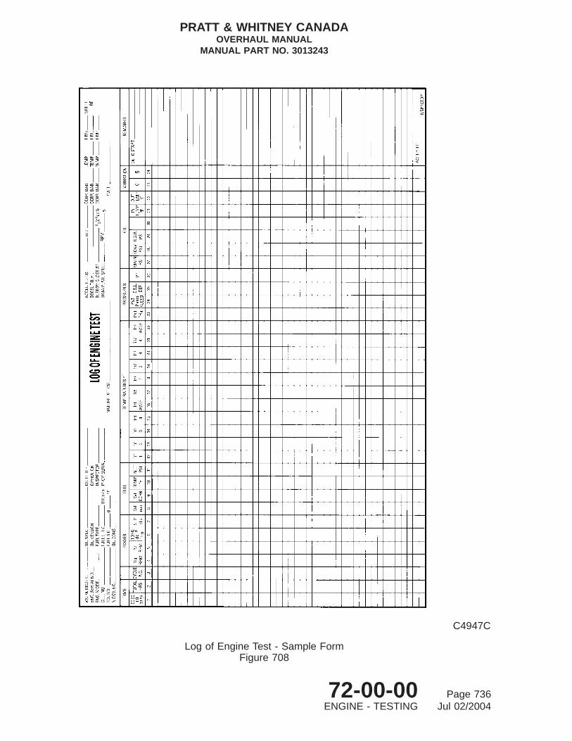
C4947C
Log of Engine Test - Sample FormFigure 708
PRATT & WHITNEY CANADAOVERHAUL MANUAL
MANUAL PART NO. 3013243
72-00-00 Page 736ENGINE - TESTING Jul 02/2004

1.4
1.6
1.8
2.0
2.2
2.4
2.6
2.8
3.0
3.2
3.4
3.6
3.8
4.0
4.2
4.4
4.6
4.8
5.0
−20 −10 0 10 20 30 40 50 60 70 80 90 100 110 120
INLET SCREEN TEMPERATURE ( F)
ACCE
LERA
TIO
N TI
ME
(SEC
OND
S)
INLETTEMPERATURE
(DEG. F)−20020405980
100120
TIME TOADD
(SECONDS).25.26.27.28.31.35.41.48
FOR ENGINES TESTED AT AN ALTITUDE OF 3000 FEET,ADD THE FOLLOWING TIME TO THE COMPUTED LIMITS.
o
C64961A
Acceleration Time vs Ambient TemperatureFigure 709
PRATT & WHITNEY CANADAOVERHAUL MANUAL
MANUAL PART NO. 3013243
72-00-00 Page 737ENGINE - TESTING Jul 02/2004

PT6A− S/N PC−E
2200
2100
2000
1900
1800
1700
1600
1500
1400
°
CORR
ECTE
D Tt
5(
R)
450 500 550 600 650 700 750 800CORRECTED SHP
500
450
400
350
300
250
CORR
ECTE
D FU
EL F
LOW
LB/
HR38000
37000
36000
35000
34000
33000
32000CORR
ECTE
D G
AS G
ENER
ATO
R RP
M (N
g)
°
CORRECTED ENGINE PERFORMANCERATING
TAKE−OFFDATA PLATE SPEEDMAX. Ng WITH TRIM STOP
SHP Ng SFC Tt5 R
RPMRPM AT T1 F
%
° OPERATOR
INSPECTOR
DATE
C7821A
Engine Performance Curve - Sample FormFigure 710
PRATT & WHITNEY CANADAOVERHAUL MANUAL
MANUAL PART NO. 3013243
72-00-00 Page 738ENGINE - TESTING Jul 02/2004

C. Underspeed Fuel Governing Check
(1) Disconnect slave tension spring, positioned between propeller governor reset armand beta valve, from reset arm (Ref. Fig. 702) and attach to front lifting bracket tomaintain beta valve in fully rearward position. Move reset arm to minimum(rear) position and secure with lockwire.
(2) Run engine, and with propeller control lever in the maximum position (propeller ordynamometer testing) (make sure dynamometer load is not excessive) graduallyadvance control lever to contact maximum Ng stop (Ref. Fig. 715 or 716, asapplicable).
(3) Record Nf which should be 31020 to 31680 rpm (PT6A-21 engines) or 31241 to31905 rpm (PT6A-27 and PT6A-28 engines) or 29869 to 30269 rpm (PT6A-27engines, DHC BS392, BS954 and Metro BS673 application only).
CAUTION: VERIFICATION OF UNDERSPEED FUEL GOVERNOR SHOULD BECOMPLETED WITHIN 5 SECONDS. ENGINE SHOULD NOT STAYRUNNING IN THE GOVERNING MODE FOR MORE THAN 10 SECONDS.
(4) Adjust propeller governor underspeed eccentric adjuster (Ref. Fig. 714) asnecessary, in increments of 1/16 of a turn to obtain this value.
(5) After satisfactory completion of check, unlock reset arm, move to forward positionand reconnect slave tension spring.
D. Maximum Ng Adjustment
NOTE: PT6A-21 engines do not require this check.
CAUTION: DO NOT EXCEED ENGINE MAXIMUM OPERATING LIMITS (REF. TABLE702).
(1) Cut lockwire that retains part power trim stop (Ref. Fig. 715) and move stop fromstowed position to operating position, to restrict power control lever travel.
NOTE: In cold weather (below 15°F) maximum torque limit may be exceeded upto a limit of 127 in.Hg for this adjustment.
(2) Start engine; with propeller control lever at maximum rpm position, advance powercontrol lever to contact part power trim stop.
(3) Adjust maximum Ng stop to obtain SHP/DEL (Ref. Fig. 718).
(4) With engine running at trim stop power confirm that Ng oscillation does not exceed50 rpm. Record Ng and Tt1.
(5) Reposition part power trim stop to its stowed position and lockwire.
PRATT & WHITNEY CANADAOVERHAUL MANUAL
MANUAL PART NO. 3013243
72-00-00 Page 739ENGINE - TESTING Jul 02/2004

E. Minimum Fuel Flow Check (Ref. Figs. 715 or 716)
CAUTION: DO NOT BLANK Py FITTING ON FCU.
(1) Disconnect Nf governor line at the FCU and blank line.
(2) Set power control lever at ground idle and record Ng.
(3) Check gas generator speed (Ng) is correct (± 300 rpm) for ambient temperatureand pressure altitude as indicated (Ref. Fig. 717).
(4) If adjustment is necessary on engines with flow divider and dump valve (Ref. Fig.716):
CAUTION: UNDER NO CIRCUMSTANCES LOOSEN NUT (8); THIS WILLDISTURB THE MAIN METERING VALVE AND NECESSITATERECALIBRATION OF THE FCU AT AN OVERHAUL FACILITY.
(a) Cut lockwire as necessary to gain access to screw (10).
(b) Hold nut (8) with wrench and carefully loosen nut (9) counterclockwise.
CAUTION: MINIMUM FLOW ADJUSTMENT IS EXTREMELY SENSITIVE ANDMUST BE MADE IN SMALL INCREMENTS.
(c) Using a 5/32 inch Allen wrench, adjust screw (10), clockwise to increase,counterclockwise to decrease Ng rpm.
(d) When specified Ng rpm has been obtained (Ref. Fig. 717), tighten nut (9)while holding screw (10), torque 20 to 25 lb.in. and lockwire.
(e) Shut down engine, reconnect Nf governor line to FCU and lockwire.
(5) If adjustment is necessary on engines with start control unit (Ref. Fig. 715):
(a) Cut lockwire, remove plug (6).
CAUTION: MINIMUM FLOW ADJUSTMENT IS EXTREMELY SENSITIVE ANDMUST BE MADE IN SMALL INCREMENTS.
(b) Using a 3/32 inch Allen wrench, adjust screw (5), clockwise to increase andcounterclockwise to decrease Ng rpm.
(c) When specified Ng rpm has been obtained (Ref. Fig. 717), shut down engine.
(d) Reinstall plug (6) and lockwire.
(e) Reconnect Nf governor line to FCU and lockwire.
PRATT & WHITNEY CANADAOVERHAUL MANUAL
MANUAL PART NO. 3013243
72-00-00 Page 740ENGINE - TESTING Jul 02/2004

0 10 20 30 40 50 60 70 80 90 100PERCENTAGE OF TBO LOGGED AGAINST ENGINE
1640
1635
1630
1625
1620
1615
1610
1605
1600
1595
1590
1585
1580
1575
1570
°
MAX
IMUM
TT5
/TH
R A
T 55
0 SH
P/DE
LRTH
(TRI
MM
ED)
C4969C
Tt5 Limits - Repair CategoryFigure 711 (Sheet 1 of 3)
PT6A-21
PRATT & WHITNEY CANADAOVERHAUL MANUAL
MANUAL PART NO. 3013243
72-00-00 Page 741ENGINE - TESTING Jul 02/2004
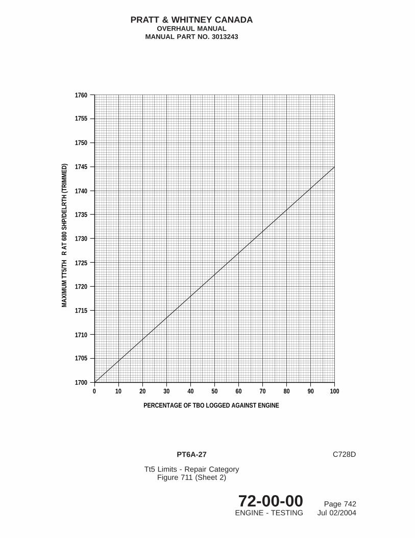
0 10 20 30 40 50 60 70 80 90 100
PERCENTAGE OF TBO LOGGED AGAINST ENGINE
1760
1755
1750
1745
1740
1735
1730
1725
1720
1715
1710
1705
1700
MAX
IMUM
TT5
/TH
R A
T 68
0 SH
P/DE
LRTH
(TRI
MM
ED)
C728D
Tt5 Limits - Repair CategoryFigure 711 (Sheet 2)
PT6A-27
PRATT & WHITNEY CANADAOVERHAUL MANUAL
MANUAL PART NO. 3013243
72-00-00 Page 742ENGINE - TESTING Jul 02/2004

0 10 20 30 40 50 60 70 80 90 100
PERCENTAGE OF TBO LOGGED AGAINST ENGINE
1740
1735
1730
1725
1720
1715
1710
1705
1695
1690
1685
1680
1700
MAX
IMUM
TT5
/TH
R A
T 68
0 SH
P/DE
LRTH
(TRI
MM
ED)
°
C11790A
Tt5 Limits - Repair CategoryFigure 711 (Sheet 3)
PT6A-27 (BS 954) / PT6A-28
PRATT & WHITNEY CANADAOVERHAUL MANUAL
MANUAL PART NO. 3013243
72-00-00 Page 743ENGINE - TESTING Jul 02/2004

0% 10% 20% 30% 40% 50% 60% 70% 80% 90% 100%
% TBO
36250
36150
36050
35950
35850
NG /
RTH
MAX
. (RP
M)
C84984
NG/RTH LimitsFigure 712 (Sheet 1 of 3)
PT6A-21
PRATT & WHITNEY CANADAOVERHAUL MANUAL
MANUAL PART NO. 3013243
72-00-00 Page 744ENGINE - TESTING Jul 02/2004

0% 10% 20% 30% 40% 50% 60% 70% 80% 90% 100%
% TBO
37400
37300
37200
37100
37000
NG /
RTH
MAX
. (RP
M)
C84985
NG/RTH LimitsFigure 712 (Sheet 2)
PT6A-27
PRATT & WHITNEY CANADAOVERHAUL MANUAL
MANUAL PART NO. 3013243
72-00-00 Page 745ENGINE - TESTING Jul 02/2004

0 10 20 30 40 50 60 70 80 90 100
NG
/RTH
(RPM
)
PERCENTAGE OF TBO LOGGED AGAINST ENGINE
37100
37000
36900
36800
36700
C74810A
NG/RTH LimitsFigure 712 (Sheet 3)
PT6A-27 (BS 954) / PT6A-28
PRATT & WHITNEY CANADAOVERHAUL MANUAL
MANUAL PART NO. 3013243
72-00-00 Page 746ENGINE - TESTING Jul 02/2004

12. Post-test Run Checks
A. Checks To Confirm Engine Acceptability or Initiate Investigation Procedure
(1) Run engine to obtain oil temperature range of 140° to 160°F. Shut down engineand, after one minute, check oil level and record.
(2) The difference between oil levels recorded in Para.8.I. and step (1) preceding,should not exceed 0.2 lb/hr maximum.
(3) Inspect engine for external oil and fuel static leakage. Remove slave oil filter fromcompressor inlet case, wipe out oil residue inside oil filter housing, and let enginestand for two hours.
NOTE: No leakage permissible from other engine locations, except as specified inTable 705.
(4) Check engine for internal oil leaks as follows:
(a) Check oil level is at maximum mark, or not more than two inches belowmaximum.
(b) Remove drain plug from 6 o’clock position on rear face of accessory gearboxand allow oil to drain.
(c) Check oil level after minimum of two hours has elapsed. Level must be sameas recorded in step (a), drain rate from accessory gearbox drain should notexceed one drop per minute.
NOTE: No leakage permissible from other engine locations, except asspecified in Table 705.
(5) Remove magnetic chip detector, if applicable, from propeller reduction gearbox.Examine chip detector and slave oil filter for contamination or metal particles.
PRATT & WHITNEY CANADAOVERHAUL MANUAL
MANUAL PART NO. 3013243
72-00-00 Page 747ENGINE - TESTING Jul 02/2004
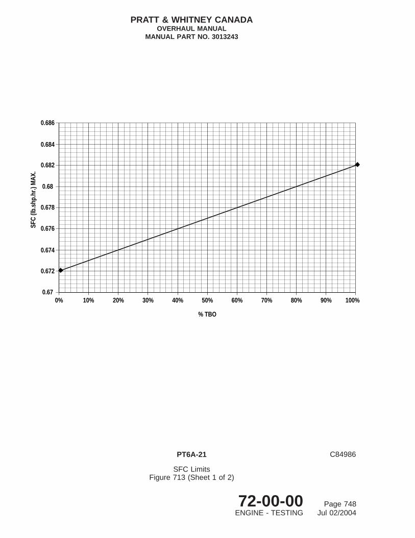
0.686
0.684
0.682
0.68
0.678
0.676
0.674
0.672
0.67
SFC
(lb.s
hp.h
r.) M
AX.
0% 10% 20% 30% 40% 50% 60% 70% 80% 90% 100%
% TBO
C84986
SFC LimitsFigure 713 (Sheet 1 of 2)
PT6A-21
PRATT & WHITNEY CANADAOVERHAUL MANUAL
MANUAL PART NO. 3013243
72-00-00 Page 748ENGINE - TESTING Jul 02/2004

0 10 20 30 40 50 60 70 80 90 100
PERCENTAGE OF TBO LOGGED AGAINST ENGINE
0.646
0.645
0.644
0.643
0.642
0.641
0.640
0.639
0.638
0.637
0.636
0.635
0.634
0.633
0.632
0.631
0.647
0.648
SFC
(lb/s
hp/h
r)
C74811A
SFC LimitsFigure 713 (Sheet 2)
PT6A-27/-28
PRATT & WHITNEY CANADAOVERHAUL MANUAL
MANUAL PART NO. 3013243
72-00-00 Page 749ENGINE - TESTING Jul 02/2004
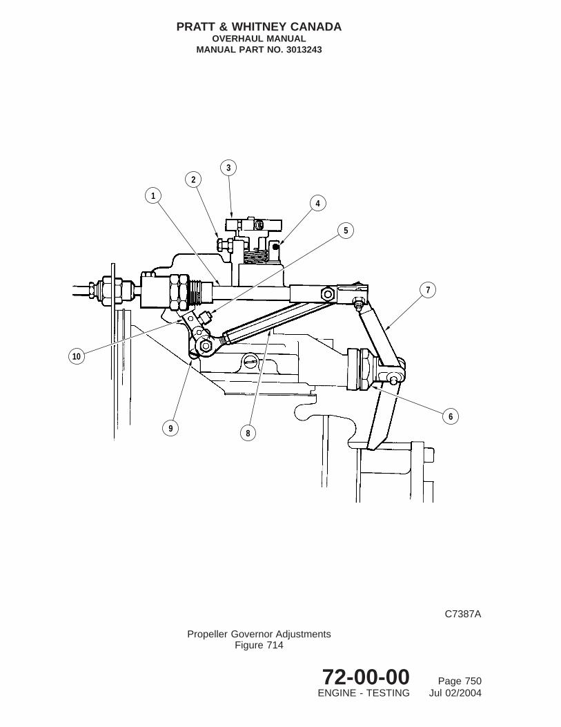
1
23
4
5
7
6
89
10
C7387A
Propeller Governor AdjustmentsFigure 714
PRATT & WHITNEY CANADAOVERHAUL MANUAL
MANUAL PART NO. 3013243
72-00-00 Page 750ENGINE - TESTING Jul 02/2004

TABLE 705, Engine Oil and Fuel Permissible Leakage
LOCATION OF DRAINMAXIMUM LEAKAGEDURING OPERATION
Engine Oil Breather 15 cc/hr
Fuel Control Unit Zero
Fuel Pump 0.55 cc/min (seepage)
Gas Generator Drain Valves Zero
Oil Consumption 0.2 lb/hr
Oil Filter Housing Check Valve 0.50 cc/hr
Start Control or Dump Valve (as applicable) 0.2 cc/min
Starter Oil Seal Cavity 3.0 cc/hr
NOTE: When a specific seal leakage is not specified, the seal leakage shall not exceed 3 ccper hour per individual seal. All seal leakages shall be included in total oil consumption.
B. If Test Results are Acceptable
(1) Install magnetic chip detector (Ref. 72-10-00, SUB-ASSEMBLY).
(2) Install new identified oil filter element in place of test slave element (Ref. FinalAssembly).
13. Unusual Oil Conditions
A. After Rectification for Unusual Oil Conditions (Ref. Light Overhaul)
(1) Ensure test cell oil system is fully charged.
(2) Fill engine oil tank.
Key to Figure 714
1. Reverse Pitch Control Rod2. Maximum Governor Speed (Nf) Adjustment3. Speed Set Lever4. Feathering Stop5. Reset Lever Maximum Stop (DO NOT ADJUST)6. Beta Valve7. Reversing Lever8. Interconnect Rod9. Reset Lever
10. Underspeed Adjustment Eccentric
PRATT & WHITNEY CANADAOVERHAUL MANUAL
MANUAL PART NO. 3013243
72-00-00 Page 751ENGINE - TESTING Jul 02/2004

VIEW A
A
1
1
STOWED POSITION
OPERATING POSITION
5 6
21
4
3
C7932C
Fuel Control Unit AdjustmentsFigure 715
PT6A-27/-28
PRATT & WHITNEY CANADAOVERHAUL MANUAL
MANUAL PART NO. 3013243
72-00-00 Page 752ENGINE - TESTING Jul 02/2004

CAUTION: OBSERVE STARTER MOTOR OPERATING LIMITS. REFER TO STARTERMANUFACTURERS MANUAL.
(3) Perform two motoring cycles to circulate oil throughout the engine oil system and fillpropeller reduction gearbox.
(4) Drain engine oil (Ref. Disassembly).
(5) Repeat steps (2) and (3) preceding.
(6) Start engine.
(7) Check engine for external oil leaks.
(8) Shut down engine and rectify oil leaks.
(9) Check tank oil level and refill, as required.
(10) Start engine and run at ground idle.
(11) With oil temperature controlled at 140°F to 160°F, check that oil pressure is 85 to95 psig at 27,000 Ng and above, and not less than 40 psig at ground idle. Ifnecessary, adjust oil pressure:
(a) Shut down engine.
(b) Drain engine oil (Ref. Disassembly).
(c) Remove oil filter cover, element housing and check valve assembly from inletcase (Ref. Disassembly).
(d) Using compressor tool ( PWC30415), remove retaining ring and relief valvefrom inlet case.
(e) Disassemble relief valve (Ref. 72-60-00).
(f) Adjust pressure by either adding or removing adjusting spacers.
NOTE: Each additional spacer will increase oil pressure approximately threeto five psig.
(g) Assemble and test relief valve (Ref. 72-60-00).
Key to Figure 715
1. Part Power Trim Stop2. Maximum Governing (Ng) Stop3. Minimum Governing (Ng) Stop4. Acceleration Adjustment Dome5. Minimum Fuel Flow Adjustment6. Plug
PRATT & WHITNEY CANADAOVERHAUL MANUAL
MANUAL PART NO. 3013243
72-00-00 Page 753ENGINE - TESTING Jul 02/2004

VIEW A
A
8
9
10
2 3
14
56 7
C8110B
Fuel Control Unit AdjustmentsFigure 716
PT6A-21
PRATT & WHITNEY CANADAOVERHAUL MANUAL
MANUAL PART NO. 3013243
72-00-00 Page 754ENGINE - TESTING Jul 02/2004

(h) Install relief valve through inlet case aperture into oil pressure pump housing;secure relief valve with retaining ring, using tool (Ref. PWC30415).
(i) Install check valve, new oil filter element and cover (Ref. Final Assembly).
(j) Check oil tank level; start engine.
(12) Check oil pressure (Ref. step (11), preceding).
(13) Remove main oil filter and chip detector and check for metal particle contamination.
(14) If heavy contamination is evident, return engine to overhaul shop for unusual oilcondition examination and inspection (Ref. Light Overhaul).
(15) Return engine to service when there is no evidence of metal contamination.
(16) Should an engine sustain propeller shaft seizure on test using a slave propellergovernor, recall governor from test cell and conduct light overhaul (Ref. 61-20-00,LIGHT OVERHAUL).
14. Preservation
Preserve engine in accordance with storage requirements (Ref. Storage Instructions).
15. Removal of Test Equipment
A. Remove Test Plumbing and Instrumentation
NOTE: Remove propeller from engine (if applicable).
(1) Refer to Para. 8. for physical location of test cell connections and plumbing.Remove interconnect drain pipes and instrumentation harness.
(2) Fit blanking caps/covers to open-ended pipes and ports of engine and test facility.
Key to Figure 716
1. Part Power Trim Stop2. Maximum Governing (Ng) Stop3. Minimum Governing (Ng) Stop4. Maximum Flow (Wf) Adjuster5. Acceleration Adjustment Dome6. Flight Idle Stop7. CUT-OFF and Flight Idle Link8. Nut9. Nut
10. Minimum Flow Adjustment Screw
PRATT & WHITNEY CANADAOVERHAUL MANUAL
MANUAL PART NO. 3013243
72-00-00 Page 755ENGINE - TESTING Jul 02/2004

°
−20 −10 0 10 20 30 40 50 60 70 80 90 100
Tt1 AMBIENT TEMPERATURE − F
23000
22000
21000
20000
19000
18000
17000
16000
GAS
GEN
ERAT
OR
SPEE
D (N
G) −
RPM
PRESSURE ALT. FT.
10000
8000
6000
4000
2000
SEA LEVEL
C13733
Ng Corrected for Temperature and AltitudeFigure 717
PRATT & WHITNEY CANADAOVERHAUL MANUAL
MANUAL PART NO. 3013243
72-00-00 Page 756ENGINE - TESTING Jul 02/2004

4000 20 40 60 80 100
450
500
550
600
650
700
Tt1 AMBIENT TEMPERATURE F
SHP/DEL
°
750
120−20
C30945A
Reduced Power Trim Curve SHP Corrected for TemperatureFigure 718
PRATT & WHITNEY CANADAOVERHAUL MANUAL
MANUAL PART NO. 3013243
72-00-00 Page 757ENGINE - TESTING Jul 02/2004

16. Install Engine in Assembly Stand
A. Remove Engine From Propeller Test Stand And Install In Assembly Stand
(1) Attach hoist to lifting eye (PWC32117) on mount ring. Take up slack on hoist chain.
(2) Unlock and remove bolts and nuts securing mount ring to test stand.
(3) Lift engine and mount ring and install in assembly stand (Ref. Storage Instructions).
(4) Disconnect and remove hoist and lifting eye.
B. Remove Engine from Dynamometer Stand and Install in Assembly Stand (Ref. Fig. 707)
(1) Drain engine oil tank (Ref. Disassembly).
(2) Remove eight nuts (20) and bolts (21) securing coupling shaft to propeller shaftflange.
(3) Attach hoist to lifting eye (PWC32081) on engine center mount ring. Take up slackon hoist.
(4) Remove nuts (15), spacers (14 and 13), and bolts (12) securing left- and right-sidemounts (3 and 1) to mount ring (2).
(5) Remove nut (7), washer (6) and bolt (11) securing bracket (5) to struts (10).
(6) Hoist engine.
(7) Remove propeller shaft plug (18); remove and discard preformed packing (19).
(8) Remove three bolts (9) and washers (8) securing bracket (5) to accessory gearbox.Remove bracket.
(9) Disconnect and remove hoist and engine sling.
(10) Remove slave nuts (16) and bolts (17) in flange A and remove mount ring (2);reinstall bolts and nuts to secure flange (Ref. 72-10-00, SUB-ASSEMBLY).
17. Remove Test Accessories
A. Remove test accessories and slave equipment (Ref. Para. 8. for item location).
B. Fit blanking caps/covers to open engine accessory ports.
18. Final Check
Return the engine to the assembly bay (overhaul shop) for security check of parts andcomponents, torque values and lockwiring (Ref. Final Assembly).
PRATT & WHITNEY CANADAOVERHAUL MANUAL
MANUAL PART NO. 3013243
72-00-00 Page 758ENGINE - TESTING Jul 02/2004

19. Power Section Run-in
NOTE: The on-wing run-in is for a power section specifically returned for unscheduledrepair (LIGHT OVERHAUL), when new sleeve bearings have been installed infirst-stage planet gears, or when three or more new sleeve bearings are installed insecond-stage planet gears in propeller reduction gearbox.
A. Incremental Run-in
CAUTION: THE FOLLOWING PROCEDURE MUST BE CONDUCTED TO THESATISFACTION OF AN APPROVED OVERHAUL FACILITY. ON COMPLETIONOF PROCEDURE, MAIN OIL FILTER MUST BE INSPECTED.
NOTE: Power sections with first and second-stage planet gears newly fitted withbronze bushings do not require run-in.
(1) Conduct pre-start and engine motoring checks with propeller feathered (refer toappropriate airframe manual).
(2) Start engine with propeller feathered (refer to appropriate airframe manual).
CAUTION: AIR INLET TEMPERATURE MUST NOT EXCEED 48.9°C (120°F). IFNECESSARY, INCREASE Np TO MAINTAIN TEMPERATURE WITHINLIMITS.
(3) Motor engine at IDLE for 10 minutes.
(4) Unfeather propeller and run engine at IDLE for 10 minutes with propeller in finepitch.
(5) Increase power gradually to obtain the following Np% maximum speeds insequence. Dwell at each speed for five minutes:
Np (percent) RPM67 147073 160079 170085 187088 194091 200096 2140100 2200
(6) Hold Np at 100% and increase torque in increments. Dwell at each torque level for10 minutes:
(a) PT6A-21 engines:
PSI LB.FT.31 957
PRATT & WHITNEY CANADAOVERHAUL MANUAL
MANUAL PART NO. 3013243
72-00-00 Page 759ENGINE - TESTING Jul 02/2004
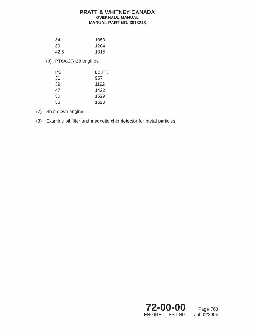
34 105039 120442.5 1315
(b) PT6A-27/-28 engines:
PSI LB.FT.31 95739 119247 142250 152953 1620
(7) Shut down engine
(8) Examine oil filter and magnetic chip detector for metal particles.
PRATT & WHITNEY CANADAOVERHAUL MANUAL
MANUAL PART NO. 3013243
72-00-00 Page 760ENGINE - TESTING Jul 02/2004

ENGINE - TROUBLESHOOTING
1. General
Figure 801 should be used as a guide during engine test to trace and rectify any problemthat may arise after scheduled or unscheduled overhaul. In some instances, the problem maybe resolved in the test cell, otherwise the engine must be returned to the overhaul shopfor unscheduled overhaul.
To facilitate troubleshooting, common engine problems are divided into four categories, eachof which contains probable symptoms of defects or malfunction in the System(s) relatedto that category. Diagnostic and corrective action required to isolate and rectify the variousproblems are linked in logic form to each of the symptoms.
2. Troubleshooting
A. Engine Problem Categories
(1) Starting Problems (Ref. Fig. 801).
(2) Operating Problems (Ref. Fig. 802).
(3) Lubricating System Problems (Ref. Fig. 803).
(4) Unacceptable Performance Parameters (Ref. Fig. 804).
PRATT & WHITNEY CANADAOVERHAUL MANUAL
MANUAL PART NO. 3013243
72-00-00 Page 801ENGINE - TROUBLESHOOTING Aug 03/2001

CONT’D SHEET 2
C7589A_1
Troubleshooting - Starting ProblemsFigure 801 (Sheet 1 of 2)
PRATT & WHITNEY CANADAOVERHAUL MANUAL
MANUAL PART NO. 3013243
72-00-00 Page 802ENGINE - TROUBLESHOOTING Aug 03/2001

FROM SHEET 1
C7589A_2
Troubleshooting - Starting ProblemsFigure 801 (Sheet 2)
PRATT & WHITNEY CANADAOVERHAUL MANUAL
MANUAL PART NO. 3013243
72-00-00 Page 803ENGINE - TROUBLESHOOTING Aug 03/2001
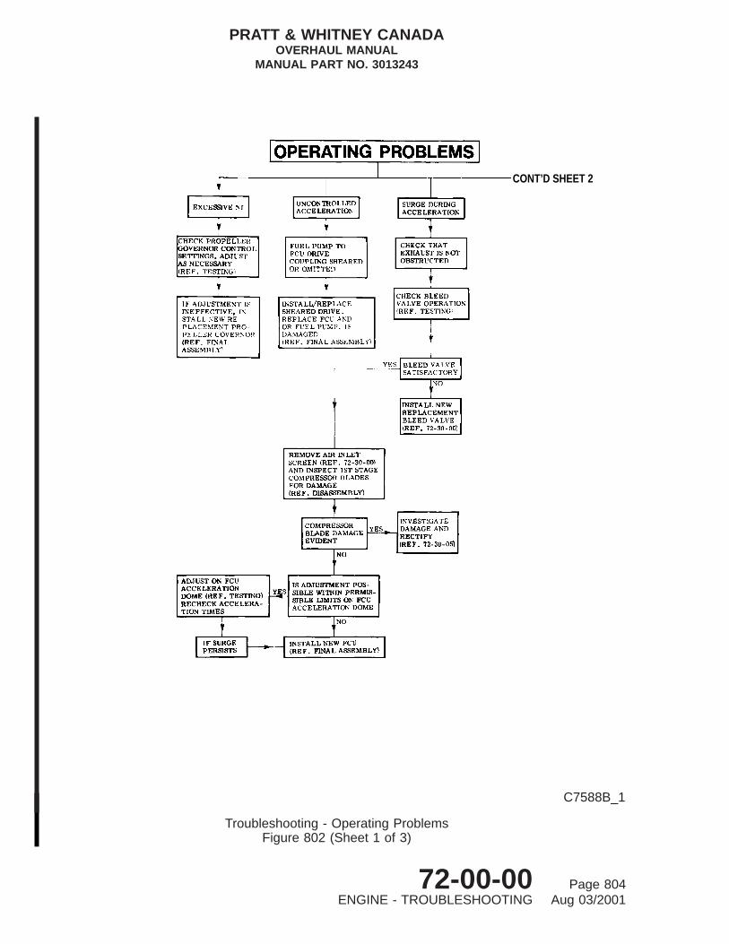
CONT’D SHEET 2
C7588B_1
Troubleshooting - Operating ProblemsFigure 802 (Sheet 1 of 3)
PRATT & WHITNEY CANADAOVERHAUL MANUAL
MANUAL PART NO. 3013243
72-00-00 Page 804ENGINE - TROUBLESHOOTING Aug 03/2001

FROM SHEET 1 CONT’D SHEET 3
C7588B_2
Troubleshooting - Operating ProblemsFigure 802 (Sheet 2)
PRATT & WHITNEY CANADAOVERHAUL MANUAL
MANUAL PART NO. 3013243
72-00-00 Page 805ENGINE - TROUBLESHOOTING Aug 03/2001

FROM SHEET 2
C7588B_3
Troubleshooting - Operating ProblemsFigure 802 (Sheet 3)
PRATT & WHITNEY CANADAOVERHAUL MANUAL
MANUAL PART NO. 3013243
72-00-00 Page 806ENGINE - TROUBLESHOOTING Aug 03/2001

THIS PAGE INTENTIONALLY LEFT BLANK
PRATT & WHITNEY CANADAOVERHAUL MANUAL
MANUAL PART NO. 3013243
72-00-00 Page 807ENGINE - TROUBLESHOOTING Aug 03/2001

CONT’D SHEET 2
C7587A_1
Troubleshooting - Lubricating System ProblemsFigure 803 (Sheet 1 of 2)
PRATT & WHITNEY CANADAOVERHAUL MANUAL
MANUAL PART NO. 3013243
72-00-00 Page 808ENGINE - TROUBLESHOOTING Aug 03/2001

C7587A_2
Troubleshooting - Lubricating System ProblemsFigure 803 (Sheet 2)
PRATT & WHITNEY CANADAOVERHAUL MANUAL
MANUAL PART NO. 3013243
72-00-00 Page 809ENGINE - TROUBLESHOOTING Aug 03/2001

C7586A
Troubleshooting - Unacceptable Performance ParametersFigure 804
PRATT & WHITNEY CANADAOVERHAUL MANUAL
MANUAL PART NO. 3013243
72-00-00 Page 810ENGINE - TROUBLESHOOTING Aug 03/2001

ENGINE - STORAGE
1. General
A. Special handling, packing, storage and preservation procedures for individual componentsor sub-assemblies are described, where necessary, in Storage Instructions of theappropriate Chapter.
B. This section provides information and procedures necessary for storage, preservationand depreservation of the complete engine, and includes handling instructions forremoving or installing the engine in its fiberboard container, metal container or stand.Two different fiberboard storage and shipping containers are in general use; Type I, madeto meet the initial requirement for shipping and storage of PT6A-27/-28 engines, TypeII, a container redesigned to smaller dimensions for use with PT6A-21/-27/-28 engines,and Type III, a reinforced fiberboard container for use with PT6A-28 engines. Areusable metal shipping container is also available, and can be used with all enginemodels.
2. Consumable Materials
The consumable materials listed below are used in the following procedures.
Item No. Name
PWC03-001 Oil, Engine LubricatingPWC03-004 Oil, LubricatingPWC05-007 Fluid, CheckPWC05-070 Tape, Pressure Sensitive AdhesivePWC07-005 Paint, EnamelPWC07-018 PrimerPWC09-003 Compound, SealingPWC11-021 CompoundPWC15-001 DELETED
3. Special Tools
The special tools listed below are used in the following procedures.
Tool No. Name Application
PWC30712 AdapterPWC30800 Engine StandPWC32080 PadPWC32081 RingPWC32389 BracketPWC32420 DELETEDPWC32327 DELETEDPWC50066 Sling As an alternate, use
PWC51861-600
PRATT & WHITNEY CANADAOVERHAUL MANUAL
MANUAL PART NO. 3013243
72-00-00 Page 901ENGINE - STORAGE May 23/2003

Tool No. Name Application
PWC51861-600 Sling Alternate to PWC50066
4. Fixtures, Equipment and Supplier Tools
Not Applicable
5. Engine Storage
A. Fiberboard Shipping Container - Type I
(1) The fiberboard shipping container, a flat-sided rectangular box, is mounted on awooden pallet. A steel cradle that holds and supports the engine assembly duringtransit and storage, is mounted within the rectangular box, and is secured to the boxinner walls with bolts, nuts and washers. For added strength, the container wallsare reinforced with wooden inner and outer stiffeners. For internal protection againstthe effects of moisture, the engine is enclosed in an evacuated, sealed plasticenvelope containing a specific quantity of dehydrated material (desiccant). Shippingcontainer and wooden pallet are firmly secured, after closure, by five steelstraps. The fiberboard box is disposable, but all other parts may be reused, subjectto condition.
(2) The fiberboard container, which must not be used for outdoor storage, or beexposed to climatic conditions for more than one week, is intended for domesticshipment in a closed conveyance on the North American continent, or for overseasshipment by air.
(3) For engine shipping container leading particulars, refer to Table 901.
B. Fiberboard Shipping Container - Type II
(1) The fiberboard shipping container is a flat-sided case consisting of a skid base, arectangular sleeve and a cover. A metal frame, bolted to the upper side of the base,carries a rubber-mounted steel cradle that holds and supports the engine assemblyduring transit and storage. For internal protection against the effects of moisture, theengine is enclosed in an evacuated, sealed plastic envelope containing a specificquantity of dehydrating material (desiccant). Cover, sleeve and base are firmlysecured after closure by five steel straps. Both the fiberboard cover and sleeveare disposable, but the base and cradle assembly may be reused, subject tocondition.
(2) The fiberboard container, which must not be used for outdoor storage, or beexposed to climatic conditions for more than one week, is intended for domesticshipment in a closed conveyance on the North American continent, or for overseasshipment by air.
(3) For engine shipping container leading particulars, refer to Table 901.
PRATT & WHITNEY CANADAOVERHAUL MANUAL
MANUAL PART NO. 3013243
72-00-00 Page 902ENGINE - STORAGE May 23/2003

C. Fiberboard Shipping Container - Type III
(1) The reinforced fiberboard shipping container is available for PT6A-28 engines andis similar in construction to the Type II, with the addition of plywood reinforced sidesand cover and modified engine support.
(2) The fiberboard container, which must not be used for outdoor storage, or beexposed to climatic conditions for more than one week, is intended for domesticshipment in a closed conveyance on the North American continent, or for overseasshipment by air.
(3) For engine shipping container leading particulars, refer to Table 901.
TABLE 901, Fiberboard Shipping Container Leading Particulars
DESCRIPTION TYPE I TYPE II TYPE III
Length 73.5 in. (1870 mm) 69.0 in. (1753 mm) 69.00 in. (1753 mm)
Width 31.5 in. (801 mm) 27.0 in. (686 mm) 33.0 in. (838 mm)
Height 37.0 in. (940 mm) 29.0 in. (737 mm) 39.0 in. (990 mm)
Weight Empty (approximate) 160 lbs. (72.5 kg) 210 lbs. (95.3 kg) 331.8 lbs. (150 kg)
D. Metal Storage and Shipping Container
(1) The metal storage and shipping container is of steel construction; manufactured intwo halves and joined at the horizontal center line. A gasket between the upper andlower halves forms a hermetic seal. The metal container is reusable and may beused for long term indoor and outdoor storage, provided the humidity level within thecontainer is frequently checked, the desiccant replenished as required, and theengine preserved in accordance with the preservation schedule (Ref. Para. 7.).
(2) The metal container is pressurized. An air filler valve and a relief valve are fitted inthe service receptacle to maintain the pressure within the container to equal 5 psiat 16°C (60°F). The service receptacle cover and service receptacle can be removedto provide access to the desiccant cage for desiccant replacement. Removal ofthe record receptacle cover will allow access to the record receptacle that providesstorage for the engine log book, shipping instructions and other documents.
(3) For metal storage and shipping container data, refer to Table 902.
TABLE 902, Fiberboard Shipping Container Leading Particulars
DESCRIPTION DATA
Length 79.0 in. (2007 mm)
Width 34.0 in. (865 mm)
Height 38.0 in. (965 mm)
Weight Empty (approximate) 400 lbs. (181.4 kg)
Pressure Tested at 10 psig
PRATT & WHITNEY CANADAOVERHAUL MANUAL
MANUAL PART NO. 3013243
72-00-00 Page 903ENGINE - STORAGE May 23/2003

TABLE 902, Fiberboard Shipping Container Leading Particulars (Cont’d)
DESCRIPTION DATA
Material Specification (Skin) SAE 1010 - 1020
Pain Primer (one coat) (PWC07-018)
Pain Finish (two coats) 332 lbs. (151 kg)(PWC07-005)
E. Humidity Control
(1) To maintain internal moisture conditions at a safe level for storage, a specificquantity of dehydrating material (desiccant) (Ref. IPC) is stowed in each type ofcontainer. The desiccant is packed in individual bags, each containing eight units(one unit weighs one ounce (28.34 g)).
(2) Each container has a humidity indicator to show the moisture level within thecontainer without disturbing the container or the contents. At a safe moisture level (upto 40 percent relative humidity) the indicator color is blue.
(3) If the internal humidity increases, the color gradually changes to pink. An all-pinkcolor indicates an unsafe moisture condition, and the desiccant must be replacedwith freshly activated material.
NOTE: Humidity indicators have a reversible element allowing them to bere-activated and reused, provided the original all-blue color is evident.Indicators need not be replaced unless damaged.
(4) Twelve bags of desiccant are used in the fiberboard container, and eight bags inthe metal container.
F. Re-activation of Desiccant
(1) Place bags of used desiccant and a pink humidity indicator in a suitable ovencontrolled at 121°C (250°F), until humidity indicator turns blue.
(2) Allow oven to cool to room temperature approximately 22°C (72°F), then removebags and indicator.
CAUTION: DO NOT REMOVE DESICCANT BAGS FROM PROTECTIVEPOLYETHYLENE ENVELOPES UNTIL REQUIRED FOR INSERTION INSHIPPING CONTAINERS.
(3) As soon as possible, after re-activation is complete, insert bags of desiccant intopolyethylene envelopes. Exclude all air and seal envelopes.
G. Storage of Engine
(1) Fiberboard Container:
PRATT & WHITNEY CANADAOVERHAUL MANUAL
MANUAL PART NO. 3013243
72-00-00 Page 904ENGINE - STORAGE May 23/2003

(a) Short term storage of engine can be accomplished in a fiberboard container,under dry conditions, up to six months. A periodic check must be carried outat least once every seven days to prevent humidity reaching an unsafe level.When indicator changes to a partially pink color, remove engine fromcontainer and protective envelope (Ref. Para. 9.).
(b) Replace old desiccant with bags of freshly activated desiccant and reinstallengine in container (Ref. Para. 12.).
(2) Metal Container
(a) Long term storage of engine must be accomplished in a metal container, whenstored indoors or outdoors.
(b) All precautions must be observed to eliminate loss of pressure and to preventhumidity reaching an unsafe level.
(c) The humidity indicator and pressure must be checked once every 30 days andrectified as necessary. Refer to Figure 907 and Table 903 PreservationSchedule for Engine in Metal Container.
H. Stacking Engine Containers for Storage
(1) Refer to instructions in Table 904 for stacking containers with or without engine.
6. Installation of Engine in Overhaul Stand
A. Engine Mounting Brackets
(1) Because the engine stand (PWC30800) can be used for engine disassembly,assembly and preparation for testing, it is necessary to select correct type ofmounting brackets, as follows:
(a) Engine Assembly in Stand/Preparation for Engine Testing: Three independant,flexible mounting brackets (PWC32080) secure engine to a mounting ring(PWC32081) that is bolted to adapters (PWC30712) attached to the enginestand.
NOTE: It is more expedient to use the above brackets for engine assembly,when engine testing in a test cell follows:
(b) Engine Disassembly: Three independant, non-flexible mounting brackets(PWC32389) secure engine to mounting ring that is bolted to adapters on theengine stand.
NOTE: These brackets may also be used for engine assembly.
(2) Installation procedure for each type of mounting bracket is described in followingparagraph.
B. Installation of Engine for Disassembly, Assembly and/or Testing (Ref. Fig. 901)
(1) Engine for disassembly and/or assembly:
PRATT & WHITNEY CANADAOVERHAUL MANUAL
MANUAL PART NO. 3013243
72-00-00 Page 905ENGINE - STORAGE May 23/2003

(a) With engine suspended from sling (8), install three non-flexible mountingbrackets (12) on engine mounting pads of gas generator case. Secure eachbracket with four bolts (13). Torque bolts 225 to 300 lb.in. and lockwire .
(2) Engine for assembly and/or testing:
(a) With engine suspended from sling (8), install three mount brackets (21)(part offlexible mounting brackets) (Ref. View C) on gas generator case mountingpads. Secure each bracket with four bolts (13). Torque bolts 225 to 300 lb.in.and lockwire.
(b) Assemble rubber mount pads (20) with sleeve, to each bracket (21) and securewith four bolts and nuts (19)(Ref. View C). Ensure offset hole in each mountpad is correctly located (Ref. View B). Tighten nuts, torque 75 to 85 lb.in. andlockwire.
(3) Locate large section of mount ring (11) on left-hand side of engine and securemount ring pads (14) to brackets at 12 o’clock and 8 o’clock positions with bolts,washers and castellated nuts. Do not tighten or lock nuts at this stage.
(4) Locate small section of mount ring (11) on right-hand side of engine, and securemount ring pad (14) to bracket at 4 o’clock position with bolt, washer and castellatednut. Do not tighten or lock nut at this stage.
(5) Install two lockplates (15) on small and large sections of mount ring (11), andsecure each lockplate with eight screws. Tighten screws, torque 225 to 300 lb.in.and lockwire.
(6) Tighten three nuts on bolts (mount ring to bracket attachment, installed in steps (3)and (4)), torque to 50 lb.in. and install cotterpins.
(7) Secure one engine mount adapter (3) to inner face of each mounting disk (16) onengine stand (18) with three bolts (4), washers (2) and nuts (1). Tighten nuts andtorque 600 to 650 lb.in. Ensure hub locking pin (17) is fully engaged.
(8) Position stand under suspended engine and carefully lower engine until two holesin lug of each adapter (3) are aligned with holes in mount ring. Secure eachadapter to mount ring with two washers (6) and bolts (7) (Ref. View A). Tightenbolts and torque 250 to 270 lb.in.
(9) Release engine weight from sling; remove sling.
7. Preservation/Depreservation of Engine
A. Depreservation of Engine
(1) Depreservation is a preliminary step before engine check run and, when necessary,before disassembly and overhaul.
(2) Purge fuel system (PT6A-21 Engines) of preservation fluid as follows:
PRATT & WHITNEY CANADAOVERHAUL MANUAL
MANUAL PART NO. 3013243
72-00-00 Page 906ENGINE - STORAGE May 23/2003

(a) Fill oil tank with approved engine oil (Ref. Testing).
NOTE: The lubrication system does not require depreservation.
(b) Connect test cell fuel supply to engine fuel inlet.
(c) Disconnect fuel line to fuel manifold at flow divider and dump valve.
CAUTION: UNDER NO CIRCUMSTANCES ALLOW PRESERVATION OIL TOENTER ENGINE WHERE IT MAY COME INTO CONTACT WITHTHERMOCOUPLE PROBE ASSEMBLY. OIL CONTAMINATION OFPROBES MAY CAUSE COMPLETE FAILURE OF THERMOCOUPLESYSTEM.
(d) Position suitable container beneath open fuel line to collect drainage.
(e) Open test cell fuel valve and switch fuel pump ON.
(f) Ensure ignition switch is OFF.
(g) Position propeller control lever at FEATHER and power control lever at TAKEOFF (fully open).
CAUTION: OBSERVE STARTER MOTOR OPERATING LIMITS. REFER TOSTARTER MANUFACTURER’S MANUAL.
(h) Motor engine until clean fuel flows from open line.
(i) Position power control lever at CUTOFF, switch fuel supply pump OFF andclose test cell fuel valve.
(j) Reconnect fuel line to flow divider and dump valve and secure line attachmentpoints.
(3) Purge fuel system (PT6A-27/-28 Engines) of preservation fluid as follows:
(a) Fill oil tank with approved engine oil (Ref. Testing).
NOTE: The lubrication system does not require depreservation.
(b) Connect test cell fuel supply to engine fuel inlet.
(c) Disconnect fuel lines at outlet side of starting flow control valve. Cap thebypass, dump and No. 1 manifold outlets, allowing drainage from No. 2 manifoldoutlet into a suitable container.
CAUTION: UNDER NO CIRCUMSTANCES ALLOW PRESERVATION OIL TOENTER ENGINE WHERE IT MAY COME INTO CONTACT WITHTHERMOCOUPLE PROBE ASSEMBLY. OIL CONTAMINATION OFPROBES MAY CAUSE COMPLETE FAILURE OF THERMOCOUPLESYSTEM.
(d) Open test cell fuel valve and switch fuel pump ON.
PRATT & WHITNEY CANADAOVERHAUL MANUAL
MANUAL PART NO. 3013243
72-00-00 Page 907ENGINE - STORAGE May 23/2003

VIEW B
VIEW C
VIEW A
13
19
20
2120
14 11
(ALTERNATE FLEXIBLEMOUNT BRACKET)
1617
11
1013121415
9
8
BA
DIRECTION OF OFFSET HOLE
OFFSET HOLE
MOUNTPADS
ENGINE MOUNT PAD OFFSET HOLELOCATIONS AS VIEWED FROM REAR
56
7
43
21
16
C7521C
Removal/Installation of Engine from StandFigure 901
PRATT & WHITNEY CANADAOVERHAUL MANUAL
MANUAL PART NO. 3013243
72-00-00 Page 908ENGINE - STORAGE May 23/2003
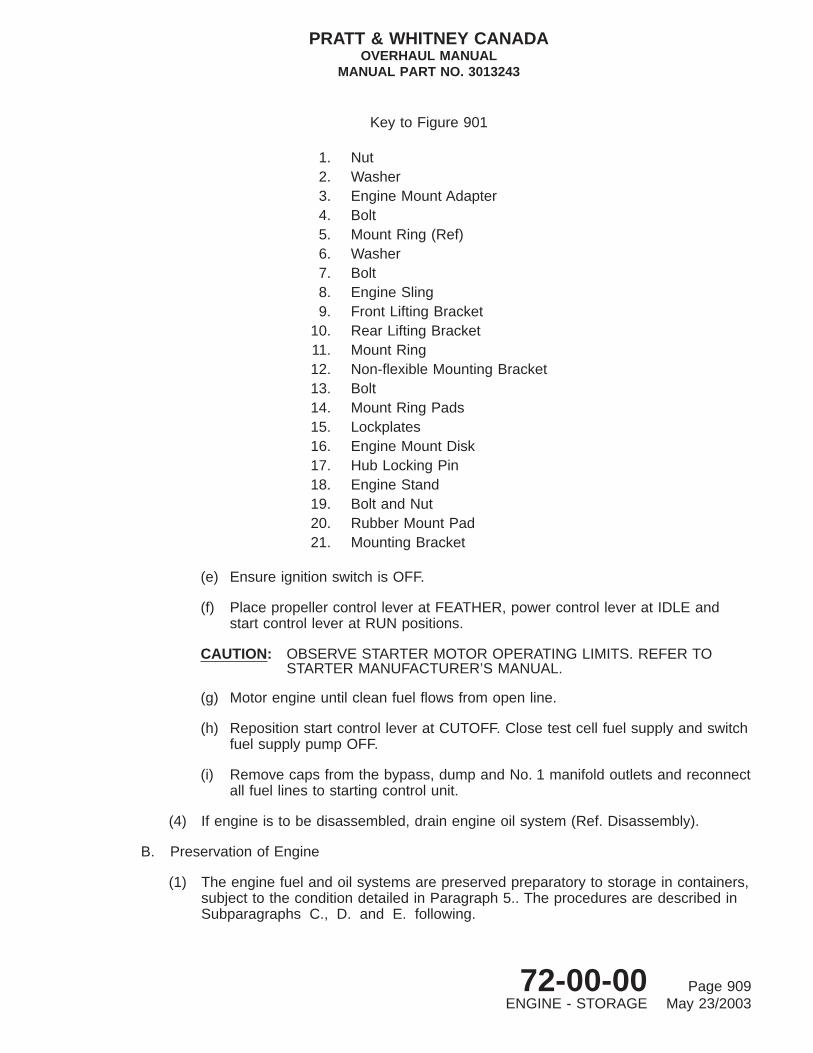
(e) Ensure ignition switch is OFF.
(f) Place propeller control lever at FEATHER, power control lever at IDLE andstart control lever at RUN positions.
CAUTION: OBSERVE STARTER MOTOR OPERATING LIMITS. REFER TOSTARTER MANUFACTURER’S MANUAL.
(g) Motor engine until clean fuel flows from open line.
(h) Reposition start control lever at CUTOFF. Close test cell fuel supply and switchfuel supply pump OFF.
(i) Remove caps from the bypass, dump and No. 1 manifold outlets and reconnectall fuel lines to starting control unit.
(4) If engine is to be disassembled, drain engine oil system (Ref. Disassembly).
B. Preservation of Engine
(1) The engine fuel and oil systems are preserved preparatory to storage in containers,subject to the condition detailed in Paragraph 5.. The procedures are described inSubparagraphs C., D. and E. following.
Key to Figure 901
1. Nut2. Washer3. Engine Mount Adapter4. Bolt5. Mount Ring (Ref)6. Washer7. Bolt8. Engine Sling9. Front Lifting Bracket
10. Rear Lifting Bracket11. Mount Ring12. Non-flexible Mounting Bracket13. Bolt14. Mount Ring Pads15. Lockplates16. Engine Mount Disk17. Hub Locking Pin18. Engine Stand19. Bolt and Nut20. Rubber Mount Pad21. Mounting Bracket
PRATT & WHITNEY CANADAOVERHAUL MANUAL
MANUAL PART NO. 3013243
72-00-00 Page 909ENGINE - STORAGE May 23/2003

C. Engine Fuel System Preservation (PT6A-21 Engines)
CAUTION: EXTREME CARE MUST BE TAKEN TO PREVENT FOREIGN MATERIALFROM BEING DRAWN INTO ENGINE FUEL SYSTEM. EQUIPMENT MUSTBE SUPPLIED WITH SUITABLE FILTERS NO COARSER THAN 10 MICRONRATING.
(1) Connect suitable oil supply line to oil-to-fuel heater fuel inlet.
(2) Disconnect fuel line at inlet to flow divider valve to prevent oil from entering fuelmanifold; loosen line as required to permit drainage into a suitable container.
CAUTION: UNDER NO CIRCUMSTANCES PERMIT PRESERVATION OIL TO ENTERENGINE WHERE IT MAY COME INTO CONTACT WITH THERMOCOUPLEPROBE ASSEMBLY. OIL CONTAMINATION OF PROBES MAY CAUSECOMPLETE FAILURE OF THERMOCOUPLE SYSTEM.
(3) Supply preservative oil (PWC03-004) at 5 to 25 psig at 16°C (60°F) through oilsupply line to engine.
(4) Ensure ignition switch is OFF.
(5) Position propeller control lever at FEATHER and power control lever at TAKE-OFF.
CAUTION: OBSERVE STARTER MOTOR OPERATING LIMITS. REFER TOSTARTER MANUFACTURER’S MANUAL.
(6) Motor engine, moving power control lever to IDLE and then to TAKE-OFF.
(7) After motoring run, check preservation oil is flowing from open fuel line. If not,repeat step (6) until oil flow appears.
(8) Return power control lever to IDLE.
(9) Reconnect fuel line to flow divider valve, and secure line attachment points.
(10) Disconnect oil supply line to oil-to-fuel heater inlet and fit blanking cap to inlet.
D. Engine Fuel System Preservation (PT6A-27/-28 Engines)
CAUTION: EXTREME CARE MUST BE TAKEN TO PREVENT FOREIGN MATERIALFROM BEING DRAWN INTO ENGINE FUEL SYSTEM. EQUIPMENT MUSTBE SUPPLIED WITH SUITABLE FILTERS NO COARSER THAN 10 MICRONRATING.
(1) Connect suitable oil supply line to oil-to-fuel heater fuel inlet.
(2) Disconnect fuel lines at outlet side of starter flow control valve. Cap bypass, dumpand No. 1 manifold outlets, allowing drainage from No. 2 manifold outlet into asuitable container.
PRATT & WHITNEY CANADAOVERHAUL MANUAL
MANUAL PART NO. 3013243
72-00-00 Page 910ENGINE - STORAGE May 23/2003

CAUTION: UNDER NO CIRCUMSTANCES ALLOW PRESERVATION OIL TO ENTERENGINE WHERE IT MAY COME INTO CONTACT WITH THERMOCOUPLEPROBE ASSEMBLY. OIL CONTAMINATION OF PROBES MAY CAUSECOMPLETE FAILURE OF THERMOCOUPLE SYSTEM.
(3) Supply preservative oil (PWC03-004) at a pressure of 5 to 25 psig and a temperatureof 16°C (60°F) through oil supply line to engine.
(4) Check ignition switch is OFF.
(5) Move power control lever to TAKE-OFF and starting control lever to RUN positions.
CAUTION: OBSERVE STARTER MOTOR OPERATING LIMITS (REFER TOSTARTER MANUFACTURER’S MANUAL).
(6) Motor engine, moving power control lever to IDLE and then to TAKE-OFF, andstarting control lever to CUT-OFF and then RUN.
(7) After motoring run, check preservative oil is flowing from No. 2 manifold outlet ofthe starting control valve. If not, repeat step (6) until oil flow appears.
(8) Return power control lever to IDLE and starting control lever to CUT-OFF.
(9) Remove caps from the bypass, dump and No. 1 manifold outlets, and reconnect allfuel lines to starting control valve.
(10) Disconnect oil supply line to oil-to-fuel heater inlet and fit blanking cap to inlet.
E. Engine Oil System Preservation
CAUTION: OBSERVE STARTER MOTOR OPERATING LIMITS (REFER TO STARTERMANUFACTURER’S MANUAL).
(1) With ignition OFF and fuel supply shut-off valve closed, motor engine with starter;when oil pressure and compressor speed (Ng) are indicated, stop motoring.
(2) Place suitable container under engine. Remove magnetic chip detector or oil drainplug, as applicable, from propeller reduction gearbox, and drain plugs fromcompressor inlet case and accessory gearbox.
CAUTION: TO MINIMIZE ENGINE OPERATION WITH LIMITED LUBRICATION, KEEPENGINE MOTORING TO SHORTEST POSSIBLE PERIOD CONSISTENTWITH COMPLETION OF DRAINING.
(3) With drains open, motor engine with starter to permit scavenge pumps to clearengine (indicated by cessation of steady oil stream from drains), then disengagestarter.
(4) Remove oil filter element (Ref. Disassembly).
(5) Allow oil to drain from engine until oil drip is slow and intermittent (approximatelyone-half hour); then install oil filter, and close drains.
PRATT & WHITNEY CANADAOVERHAUL MANUAL
MANUAL PART NO. 3013243
72-00-00 Page 911ENGINE - STORAGE May 23/2003

(6) Remove cover plates from pads of accessory drives, and spray exposed surfacesand gearshaft with engine lubricating oil (PWC03-004). Replace cover plates.
(7) Install plugs, caps and covers to all engine openings to prevent moistureaccumulation and entry of foreign material (Ref. Fig. 902)
NOTE: Some PT6A-27 models (Post-SB1152) have additional hardware shippedwith engine.
(8) Tag oil filler cap with date of preservation.
8. Removal of Engine from Stand (Ref. Fig. 902)
A. Procedure
(1) Attach sling (PWC50066) or (PWC51861-600) to engine lifting points (9) and (10),and take up slack on hoist.
(2) Remove bolts (7) and washers (6) securing mount ring (11) to both engine mountadapters (3).
(3) Lift engine clear of stand.
(4) Remove eight screws securing each lockplate (15) to small and large sections ofmount ring (11). Remove lockplates.
(5) Remove cotterpins, castellated nuts and bolts from mount ring pads (14) on largesection of mount ring (11), and separate from brackets at 12 o’clock and 8 o’clockpositions.
(6) Support small section of mount ring (11) and remove cotterpin, castellated nut andbolt securing mount ring pad (14) of mount ring to mounting bracket at 4 o’clockposition on engine.
NOTE: After removal, retain all nuts, bolts, washers and both lockplates in asuitable bag, and attach to stand.
(7) Remove bolts (13) and separate three mount brackets (12) or (21) from gasgenerator case. Retain brackets with stand.
9. Removal of Engine From Container
A. Procedure
(1) When an engine is to be removed from, or installed in, a container, the followingprecautions must be taken.
(a) Ensure that a hoist of sufficient lifting capacity and safety factor is available tolift the following loads:
1 350 lbs. (159 kg) engine only.
2 800 lbs. (363 kg) engine loaded in container.
PRATT & WHITNEY CANADAOVERHAUL MANUAL
MANUAL PART NO. 3013243
72-00-00 Page 912ENGINE - STORAGE May 23/2003

(b) Position container or engine correctly on floor directly beneath hoist.
(c) A free overhead space of approximately six feet (approx. two meters) from thefloor to the hoist hook is required to remove the engine from the container.
B. Removal of Engine from Type I Fiberboard Container (Ref. Fig. 903)
(1) Cut and remove steel strapping (15) from around fiberboard container. Retainreinforcing corners (16).
(2) Cut sealing tape and fold back flaps on top of container.
(3) Cut protective envelope and expose top of engine.
CAUTION: NEVER USE ENGINE LIFTING BRACKETS TO RAISE ENGINE ANDCRADLE ASSEMBLY WHEN ATTACHED TO CONTAINER.
(4) Attach engine sling (PWC50066) or (PWC51861-600) to engine lifting brackets atflanges A and G. Adjust lifting eye of sling to obtain an even lift.
(5) Take weight of engine on sling and remove eight bolts (18) and lockwashers (19)securing cradle to mounting brackets (14).
(6) Slowly lift engine and cradle assembly; ensure that engine remains level and is notpermitted to swing.
(7) Transfer engine to clear area and remove cradle from engine by removingquick-release pins (21) from engine mount brackets (11) and (12).
(8) Remove 11 bolts and washers securing two engine front mount brackets (11) andone engine rear mount bracket (12). Replace mount brackets (11) and (12) oncradle (13) and secure with quick- release pins (21). Place bolts and washers in clothor polyethylene bag and secure to cradle.
(9) Retain cradle (13), wooden pallet (8) and associated hardware for reuse. Discardnon-reusable items.
(10) Remove protective envelope (9).
(11) Remove 12 desiccant bags from engine and retain for re-activation and reuse.
(12) Remove shipping data envelope and envelope containing engine log books frombottom of containers.
C. Removal of Engine from Type II Fiberboard Container (Ref. Fig. 904)
(1) Cut and remove steel strapping (3) and (10) from around fiberboard container.Retain reinforcing corners (2) and (9). Remove cover (1) and sleeve (5) fromskid base (17).
(2) Cut protective envelope (7) and expose top of engine.
PRATT & WHITNEY CANADAOVERHAUL MANUAL
MANUAL PART NO. 3013243
72-00-00 Page 913ENGINE - STORAGE May 23/2003

30
28
29
27
31
VIEW A
A35 34UNDERSIDE VIEW
VIEW A
32
33
10
OIL−FUEL−HEATER
FRONT VIEW
1
23 4
56
13
1
11
128
7
9
39
REAR VIEW
POST−SB1482
14 15 1618
20
21
17
19
36
37
222338
2425122612
C8515A
Location of Shipping Covers and PlugsFigure 902
PRATT & WHITNEY CANADAOVERHAUL MANUAL
MANUAL PART NO. 3013243
72-00-00 Page 914ENGINE - STORAGE May 23/2003

Key to Figure 902
1. Exhaust Duct Shipping Cover2. Tachometer Drive Shipping Cover3. Oil Pressure Boss Plug4. Electrical Connector Shipping
Cap (Propeller Governor)5. Torquemeter Transmitter
Connection Shipping Cap6. Torquemeter Transmitter Shipping
Cover*7. Bolt*8. Washer*9. Nut10. Fuel Heater Shipping Plug11. Electrical Connector Shipping
Cap(PK247 Ignition Regulator Box)(PK265 Ignition Exciter Box)
12. Accessory Drives, ShippingCovers
13. Starter-generator Mount ShippingCover
14. Oil Return Adapter ShippingCover
15. Mount Cover Bolt16. Center Engine Mount Shipping
Cover17. Oil Vent Shipping Cover18. Bolt19. Washer20. Thermocouple Connector
Shipping Cap21. Electrical Connector Shipping
Cap
22. Oil Pressure Boss Plug23. Oil Temperature Connector Plug24. Scavenge Oil Connector Shipping
Cap25. Scavenge Oil Connector Shipping
(PT6A-27/-28 Engines)26. Starter-generator Cavity Drain
Dust Cap*27. Nut*28. Washer*29. Bolt30. Propeller Shaft Flange Shipping
Cover31. Case Drain Shipping Caps32. Scavenge Oil Tee Shipping Cap33. Fuel Drain Shipping Cap34. Fuel Drain Shipping Cap35. Air Inlet Shipping Cover
**36. Fuel Control Unit Shaft ProtectiveCap
37. Protective Dust Cap***38. Protective Dust Cap
39. Electrical Connector ShippingCap
* (Parts not required when‘‘press-on’’ covers are provided)
** (Fitted to PT6A-27 Enginesshipped without propellerreversing linkage)
*** (Fitted to PT6A-28 Engineshaving flexible hose deleted)
PRATT & WHITNEY CANADAOVERHAUL MANUAL
MANUAL PART NO. 3013243
72-00-00 Page 915ENGINE - STORAGE May 23/2003

22
8
4
3
6
2
13
5
7
5
3
9
16
20
15
18
19
1417
211121
1312 21 11 10
C8514
Fiberboard Container Components - Type IFigure 903
PRATT & WHITNEY CANADAOVERHAUL MANUAL
MANUAL PART NO. 3013243
72-00-00 Page 916ENGINE - STORAGE May 23/2003

CAUTION: NEVER USE ENGINE LIFTING BRACKETS TO RAISE ENGINE ANDCRADLE ASSEMBLY WITH SKID BASE ATTACHED.
(3) Attach engine sling (PWC50066) or (PWC51861-600) to engine lifting brackets atflanges A and G. Adjust lifting eye of sling to obtain an even lift.
(4) Take weight of engine on sling, remove quick-release pins (11) and (13) securingengine mount brackets (12) and (14) to cradle (15).
(5) Raise engine in level attitude until clear of cradle.
(6) Remove 11 bolts and washers securing two engine front mount brackets (12) andone engine rear mount bracket (14) to engine. Replace mount brackets (12) and(14) on cradle and secure with quick-release pins (11) and (13). Place bolts andwashers in cloth or polyethylene bag and secure to cradle.
(7) Retain cradle, skid base and associated hardware for reuse. Remove protectiveenvelope (7).
(8) Remove 12 desiccant bags from engine and retain for re-activation and reuse.
Key to Figure 903
1. Inner Stiffener2. Bolt3. Plain Washer4. Outer Stiffener5. Self-locking Nut6. Reinforcing Plate7. Sheat Mount8. Pallet9. Engine Protective Envelope
10. Gaskets11. Engine Mount Forward Brackets12. Engine Mount Rear Bracket13. Cradle14. Mounting Bracket15. Steel Strapping16. Reinforcing Corners17. Screw18. Bolt19. Lockwasher20. Humidity Indicator21. Quck-release Pins22. Slotted Box
PRATT & WHITNEY CANADAOVERHAUL MANUAL
MANUAL PART NO. 3013243
72-00-00 Page 917ENGINE - STORAGE May 23/2003

(9) Remove shipping data envelope and envelope containing engine log book from boxglued to skid base.
D. Removal of Engine from Type III Fiberboard (reinforced) Container (Ref. Fig. 905)
(1) Cut and remove steel strapping (4) from around fiberboard container. Retainreinforcing corners (24). Remove cover (1) and sleeve (10) from skid base (12).Retain plywood panels (3), (5) and (6) if condition permits.
(2) Cut protective envelope (8) and expose top of engine.
CAUTION: NEVER USE ENGINE LIFTING BRACKETS TO RAISE ENGINE ANDCRADLE ASSEMBLY WITH SKID BASE ATTACHED.
(3) Attach engine sling (PWC50066) or (PWC51861-600) to engine lifting brackets atflanges A and G. Adjust lifting eye of sling to obtain an even lift.
(4) Take weight of engine on sling and remove eight nuts (14) and bolts (16) securingengine support (22) to cradle mounting (13). Retain all hardware.
(5) Slowly lift engine and support; ensure that engine remains level and is notpermitted to swing.
(6) Remove nuts (26), bolts (15) securing engine support (22) to lower mount brackets(25).
(7) Remove quick-release pin (17) from upper mount bracket (27) and lift support (22)away from engine. Secure support (22) to cradle mounting (13) with bolts (16) andnuts (14).
(8) Remove bolts and washers securing lower mount brackets (25) and upper mountbracket (27) to engine. Secure brackets (25) and (27) to support (22) with bolts(15), nuts (26) and pin (17) respectively.
(9) Remove and discard protective envelope (8).
(10) Remove 12 desiccant bags from engine and retain for re-activation and reuse.
(11) Remove shipping data envelope and envelope containing engine log books frombottom of containers.
(12) Remove box containing ignition exciter (if applicable) taped to bottom of container.
E. Removal of Engine from Metal Container (Ref. Fig. 906)
(1) Observe precautions (Ref. Para. 9.A., preceding).
(2) Remove service receptable cover (1) by removing two nuts and lockwashers.
CAUTION: ALLOW A MINIMUM OF 10 MINUTES FOR ALL PRESSURE TO BERELEASED BEFORE SEPARATING HALVES OF CONTAINER.
(3) Depressurize container by allowing air to escape through air filler valve (2).
PRATT & WHITNEY CANADAOVERHAUL MANUAL
MANUAL PART NO. 3013243
72-00-00 Page 918ENGINE - STORAGE May 23/2003

(4) Remove 36 nuts, washers and bolts securing container top cover to container base.
(5) With hoist attached to container lifting points (8), lift container top cover verticallyto clear locating pin (6). Rest container top cover on clean, wooden blocks.
(6) Attach engine sling (PWC50066) or (PWC51861-600) to front and rear liftingbrackets at flanges A and G. Adjust lifting eye of sling to obtain level lift.
CAUTION: NEVER USE ENGINE LIFTING BRACKETS TO LIFT AN ENGINE STILLATTACHED TO THE METAL CONTAINER BASE.
(7) Take weight of engine on sling and remove three quick-release pins (9) securingengine mount brackets to mounting cradle.
(8) If difficulty is experienced when attempting to remove quick- release pins (9), usethe following alternative method for removing engine:
(a) Remove eight bolts, washers and nuts securing mounting cradle (11) tocontainer.
(b) Slowly raise engine, together with mounting cradle from container.
(c) Separate engine from cradle as described in following step (10).
(9) Raise engine slowly from container. Ensure that engine remains horizontal anddoes not swing.
(10) Remove 11 bolts and washers securing two front mount brackets and one rearmount bracket to engine. Replace mount brackets on cradle (11) and secure withquick-release pins (9). Place bolts and washers in cloth or polyethylene bag andsecure to cradle.
(11) Remove four nuts and lockwashers, two studs and two bolts, and withdraw servicereceptacle (3) from container base.
(12) Remove eight desiccant bags from desiccant case, and retain them for re-activationand reuse (Ref. Para. 5.E.).
(13) Remove record receptacle cover by removing two nuts, washers and bolts.
(14) Withdraw engine log book and any other documents from record receptacle (5).Replace cover, bolts, washers and nuts.
(15) Remove all shipping covers, caps and plugs from engine, place in suitable bag andsecure to cradle.
(16) Clean interior of container.
(17) Replace top cover and secure with 36 bolts, washers and nuts.
(18) Coat all exposed hardware with preservative oil (PWC03-001).
PRATT & WHITNEY CANADAOVERHAUL MANUAL
MANUAL PART NO. 3013243
72-00-00 Page 919ENGINE - STORAGE May 23/2003

C3868B
Fiberboard Container Components - Type IIFigure 904
PRATT & WHITNEY CANADAOVERHAUL MANUAL
MANUAL PART NO. 3013243
72-00-00 Page 920ENGINE - STORAGE May 23/2003

(19) Retain moisture barrier/protective wrapping on engine, air inlet screen untildisassembly of engine.
10. Installation of Engine in Fiberboard Container
A. Preparation
CAUTION: ENSURE ENGINE HAS BEEN COMPLETELY DRAINED OF OIL.
(1) Observe lifting precautions (Ref. Para. 9.A.).
(2) With engine mounted in stand (PWC30800) and engine preservation accomplished(Ref. Para. 7..B.), fit all shipping covers and plugs (Ref. Fig. 902).
(3) Enclose air inlet screen with shipping cover (35, Fig. 902).
(4) Ensure all reusable container parts are serviceable, and all non- reusable partshave been replaced with new parts.
(5) Remove the ignition exciter (if applicable) and tape the ignition cables to the engineusing pressure-sensitive tape (PWC05-070).
B. Installation of Engine in Type I Fiberboard Container (Ref. Fig. 903)
(1) Open container slotted box (22) and fold bottom end flaps inwards, followed by sideflaps.
Key to Figure 904
1. Cover2. Reinforcing Corners3. Steel Strap4. Pressure Sensitive Tape5. Sleeve6. Humidity Indicator7. Protective Envelope8. Gaskets9. Reinforcing Corners
10. Steel Strap11. Quick-release Pin12. Front Mount Brackets13. Quick-release Pin14. Rear Mount Bracket15. Cradle16. Shear Mounts17. Skid Base
PRATT & WHITNEY CANADAOVERHAUL MANUAL
MANUAL PART NO. 3013243
72-00-00 Page 921ENGINE - STORAGE May 23/2003

5
4
3
21
10
11
9
5
8
7
22
618 1920
21
27
23
24
13
14
15
16
25
17
26
12
C13572
Fiberboard Container Components - Type IIIFigure 905
PRATT & WHITNEY CANADAOVERHAUL MANUAL
MANUAL PART NO. 3013243
72-00-00 Page 922ENGINE - STORAGE May 23/2003

(2) Using pressure-sensitive tape (PWC05-070), seal middle seam, overlapping 10 to 12inches on sides. Tape bottom edges at each end and extend around sidesapproximately 12 inches.
(3) Resting inner stiffener (1) on bottom of container (inside) as template, drill or punchsix 0.437 inch holes.
(4) Repeat step (3) on opposite side.
(5) Install two bolts (2) with two plain washers (3) in upper holes of outer stiffener (4)and attach to outside of container box (22). Install inner stiffener over bolts frominside container and loosely attach with plain washers (3) and self-locking nuts (5).
(6) In each lower pair of holes, install bolts through reinforcing plate (6) and containerbox (22). Install shear mounts (7) over protruding ends of bolts and loosely securewith plain washers (3) and self-locking nuts (5).
Key to Figure 905
1. Cover2. Corner, Reinforcing3. Top, Plywood4. Seal, Strapping5. End, Plywood6. Side, Plywood7. Gaskets8. Protective Envelope9. Humidity Indicator
10. Sleeve, Fiberboard11. Tape12. Skid Base13. Cradle Mounting14. Nut15. Bolt16. Bolt17. Quick-release Pin and Lanyard18. Bolt19. Swivel Mount20. Washer21. Split Pin22. Engine Support23. Strapping24. Corner, Reinforcing25. Bracket, Mounting - Lower26. Nut27. Bracket, Mounting - Upper
PRATT & WHITNEY CANADAOVERHAUL MANUAL
MANUAL PART NO. 3013243
72-00-00 Page 923ENGINE - STORAGE May 23/2003
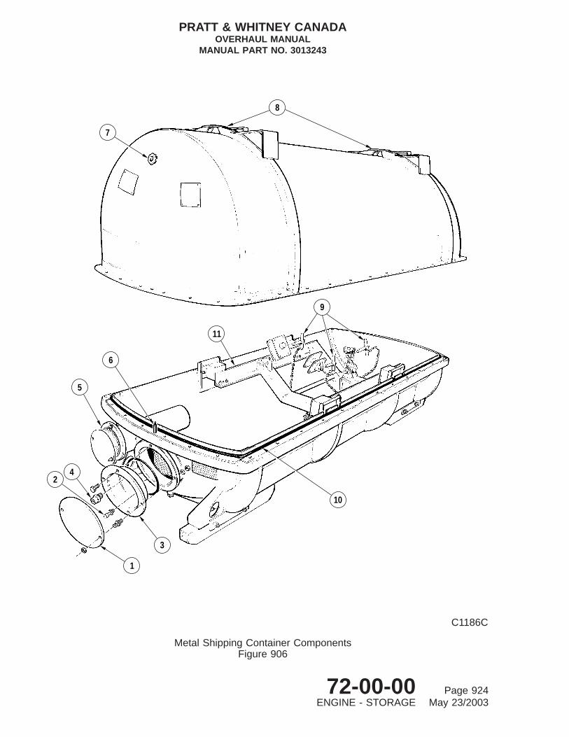
7
8
11
9
10
1
3
42
6
5
C1186C
Metal Shipping Container ComponentsFigure 906
PRATT & WHITNEY CANADAOVERHAUL MANUAL
MANUAL PART NO. 3013243
72-00-00 Page 924ENGINE - STORAGE May 23/2003

(7) Repeat steps (5) and (6) on opposite side. Tighten all 12 bolts and torque 80 to90 lb.in.
(8) Install four mounting brackets (14) to shear mounts (7) using screws (17).
(9) Place container on pallet (8).
(10) Attach sling (PWC50066) or (PWC51861-600) to engine lifting points and take upslack on hoist.
(11) Remove engine from stand as described in Paragraph 8.. Ensure mountingbrackets have been removed from gas generator case and attached to stand.
(12) Check that interior of protective envelope is free of dirt, oil, water and othercontaminants.
(13) Install new, protective envelope (9) under engine, aligning gaskets (10) with lowerengine mounting pads on each side of engine, and accessory gearbox mountingpad.
CAUTION: STANDARD COMMERCIAL HARDWARE MUST NOT BE USED TOSECURE ENGINE SUPPORT BRACKETS TO ENGINE OR CONTAINER.HARDWARE OF LOWER STRENGTH COULD CAUSE SERIOUS ENGINEDAMAGE DURING SHIPPING.
(14) Attach container front mount brackets (11) to engine lower mounting pads, eachside of gas generator case, with eight bolts and lockwashers. Tighten bolts andtorque 275 to 300 lb.in.
(15) Attach container rear mount bracket (12) to mounting pad at 6 o’clock position onaccessory gearbox with three bolts and lockwashers. Tighten bolts and torque 50 to70 lb.in.
(16) Retain engine log book and relevant papers in waterproof envelopes and seal withpressure-sensitive tape (PWC05-070). Insert envelopes in suitable box and secureto bottom of engine container.
Key to Figure 906
1. Service Receptacle Cover2. Air Filler Valve3. Service Receptacle4. Relief Valve5. Record Receptacle6. Container Locating Pins7. Humidity Indicator8. Container Lifting Points9. Quick-release Pins
10. Container Gasket11. Mounting Cradle
PRATT & WHITNEY CANADAOVERHAUL MANUAL
MANUAL PART NO. 3013243
72-00-00 Page 925ENGINE - STORAGE May 23/2003

(17) Attach cradle (13) to engine mount brackets (previously installed) with quick-releasepins (21).
(18) Secure humidity indicator (20) to protective envelope.
(19) Lower engine and cradle assembly carefully into container; align upward locatingpins protruding from four mounting brackets (14) with four holes in cradle.
(20) Secure cradle to mounting brackets with eight bolts (18) and lockwashers (19).
(21) Tie 12 (eight-ounce) freshly activated desiccant bags to engine; evenly dispose overengine length, six top and bottom.
NOTE: Remove desiccant bags from protective polyethylene bags beforeinstallation.
(22) Heat seal along top of envelope using suitable hand soldering iron, leaving onecorner open. Evacuate air, fold corner and heat seal.
(23) Fold protective envelope and check that humidity indicator aligns with window incontainer. Tape envelope folds with pressure-sensitive tape (PWC05-070).
(24) First fold end flaps of container inward, then fold side flaps.
(25) Using pressure-sensitive tape (PWC05-070), seal middle seam and overlap endsand extend around sides approximately 8 inches. Tape edges at both ends andextend around side approximately 12 inches.
(26) Secure container to pallet with five sets of 3/4 inch commercial steel strapping (15)over 10 reinforcing corners (16).
(27) Stencil engine model and serial number, inspection, preservation and packagingdates on both ends of container.
C. Installation of Engine in Type II Fiberboard Container (Ref. Fig. 904)
(1) Attach sling (PWC50066) or (PWC51861-600) to engine lifting points and take upslack on hoist.
(2) Remove engine from stand (Ref. Para. 8., preceding). Ensure mounting bracketshave been removed from gas generator case and attached to stand.
(3) Check that interior of protective envelope is free of dirt, oil, water and othercontaminants.
(4) Install new, protective envelope (7) under engine, aligning gaskets (8) with lowerengine mounting pads on each side of engine and accessory gearbox mountingpad.
PRATT & WHITNEY CANADAOVERHAUL MANUAL
MANUAL PART NO. 3013243
72-00-00 Page 926ENGINE - STORAGE May 23/2003

CAUTION: STANDARD COMMERCIAL HARDWARE MUST NOT BE USED TOSECURE ENGINE SUPPORT BRACKETS TO ENGINE OR CONTAINER.USING HARDWARE OF LOWER STRENGTH THAN SPECIFIEDCOULD CAUSE SERIOUS ENGINE DAMAGE DURING SHIPPING.
(5) Attach container front mount brackets (12) to engine lower mounting pads, eachside of gas generator case, with eight bolts and lockwashers. Tighten bolts andtorque 275 to 300 lb.in.
(6) Attach container rear mount bracket (14) to mounting pad at 6 o’clock position onaccessory gearbox with three bolts and lockwashers. Tighten bolts and torque 50 to70 lb.in.
(7) Place engine log book and relevant papers in waterproof envelopes and seal withpressure-sensitive tape (PWC05-070). Insert envelopes in box glued to bottom ofskid base, and seal box.
(8) Lower engine into cradle (15) on skid base (17), and secure mount brackets (12)and (14) to cradle with three quick-release pins (11) and (13).
(9) Remove hoist and sling from engine.
(10) Secure humidity indicator (6) to protective envelope.
(11) Tie 12 (eight-ounce) freshly activated desiccant bags to engine; evenly dispose overengine length, six top and bottom.
NOTE: Remove desiccant bags from protective polyethylene bags beforeinstallation.
(12) Heat seal along top of envelope using suitable hand soldering iron, leaving onecorner open. Evacuate air, fold corner and heat seal.
(13) Install fiberboard sleeve (5) over engine and fit in position on skid base (17).
(14) Fold protective envelope, and check that humidity indicator (6) aligns with windowin sleeve. Tape envelope folds with pressure-sensitive tape (PWC05-070).
(15) Close flaps of sleeve and seal with pressure-sensitive tape (4).
(16) Place cover (1) on sleeve, fold flaps down and seal at each corner withpressure-sensitive tape (4).
(17) Secure cover horizontally with 3/4-inch commercial steel strapping (3) and fourreinforcing corners (2).
(18) Secure cover and sleeve to skid base with 3/4-inch steel strapping (10) and 16reinforcing corners (9).
(19) Stencil engine model and serial number, inspection, preservation and packagingdates on both ends of container.
PRATT & WHITNEY CANADAOVERHAUL MANUAL
MANUAL PART NO. 3013243
72-00-00 Page 927ENGINE - STORAGE May 23/2003
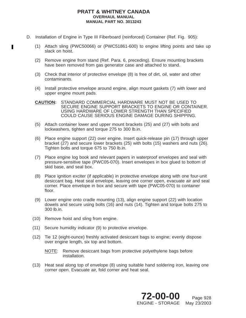
D. Installation of Engine in Type III Fiberboard (reinforced) Container (Ref. Fig. 905):
(1) Attach sling (PWC50066) or (PWC51861-600) to engine lifting points and take upslack on hoist.
(2) Remove engine from stand (Ref. Para. 6, preceding). Ensure mounting bracketshave been removed from gas generator case and attached to stand.
(3) Check that interior of protective envelope (8) is free of dirt, oil, water and othercontaminants.
(4) Install protective envelope around engine, align mount gaskets (7) with lower andupper engine mount pads.
CAUTION: STANDARD COMMERCIAL HARDWARE MUST NOT BE USED TOSECURE ENGINE SUPPORT BRACKETS TO ENGINE OR CONTAINER.USING HARDWARE OF LOWER STRENGTH THAN SPECIFIEDCOULD CAUSE SERIOUS ENGINE DAMAGE DURING SHIPPING.
(5) Attach container lower and upper mount brackets (25) and (27) with bolts andlockwashers, tighten and torque 275 to 300 lb.in.
(6) Place engine support (22) over engine. Insert quick-release pin (17) through upperbracket (27) and secure lower brackets (25) with bolts (15) washers and nuts (26).Tighten bolts and torque 675 to 750 lb.in.
(7) Place engine log book and relevant papers in waterproof envelopes and seal withpressure-sensitive tape (PWC05-070). Insert envelopes in box glued to bottom ofskid base, and seal box.
(8) Place ignition exciter (if applicable) in protective envelope along with one four-unitdesiccant bag. Heat seal envelope, leaving one corner open, evacuate air and sealcorner. Place envelope in box and secure with tape (PWC05-070) to containerfloor.
(9) Lower engine onto cradle mounting (13), align engine support (22) with locationdowels and secure using bolts (16) and nuts (14). Tighten and torque bolts 275 to300 lb.in.
(10) Remove hoist and sling from engine.
(11) Secure humidity indicator (9) to protective envelope.
(12) Tie 12 (eight-ounce) freshly activated desiccant bags to engine; evenly disposeover engine length, six top and bottom.
NOTE: Remove desiccant bags from protective polyethylene bags beforeinstallation.
(13) Heat seal along top of envelope (8) using suitable hand soldering iron, leaving onecorner open. Evacuate air, fold corner and heat seal.
PRATT & WHITNEY CANADAOVERHAUL MANUAL
MANUAL PART NO. 3013243
72-00-00 Page 928ENGINE - STORAGE May 23/2003

(14) Install fiberboard sleeve (10) complete with plywood panels (5) and (6) over engineand fit in position on skid base (12).
(15) Fold protective envelope, and check that humidity indicator (9) aligns with windowin sleeve. Tape envelope folds with pressure-sensitive tape (PWC05-070).
(16) Close flaps of sleeve and seal with pressure-sensitive tape (11).
(17) Place cover (1) complete with plywood top panel (3) on sleeve, fold flaps down andseal at each corner with pressure-sensitive tape (11).
(18) Secure cover horizontally with 3/4-inch commercial steel strapping (23) and fourreinforcing corners (2).
(19) Secure cover and sleeve to skid base with 3/4-inch commercial steel strapping (23)and 16 reinforcing corners (24).
(20) Secure cover and sleeve to skid base with 3/4-inch commercial steel strapping (23)and 16 reinforcing corners (24).
(21) Stencil engine model and serial number, inspection, preservation and packagingdates on both ends of container.
11. Installation of Engine in Metal Container
A. Procedure
CAUTION: ENSURE OIL HAS BEEN COMPLETELY DRAINED FROM ENGINE.
(1) Refer to Paragraph 9.A. and observe lifting precautions.
(2) With engine mounted in stand (Ref. Para. 6.) and engine preservation procedureaccomplished (Ref. Para. 7.), install all shipping covers and plugs (Ref. Fig. 902).
(3) Install shipping cover over air intake screen.
(4) Top and bottom interior halves of metal container must be clean and dry.
(5) Mating flanges of top and bottom halves of metal container must be clean and freeof damage. A new gasket (10, Fig. 906) must be used on container.
(6) Attach sling (PWC50066) or (PWC51861-600) to engine lifting points and take upslack on hoist.
(7) Remove engine from stand (Ref. Para. 8.). Ensure mounting brackets have beenremoved from gas generator case and attach to stand.
PRATT & WHITNEY CANADAOVERHAUL MANUAL
MANUAL PART NO. 3013243
72-00-00 Page 929ENGINE - STORAGE May 23/2003

CAUTION: STANDARD COMMERCIAL HARDWARE MUST NOT BE USED TOSECURE ENGINE SUPPORT BRACKETS TO ENGINE OR CONTAINER.USING HARDWARE OF LOWER STRENGTH THAN SPECIFIEDCOULD CAUSE SERIOUS ENGINE DAMAGE DURING SHIPPING.
(8) Attach container front mount brackets to engine lower mounting pads on each sideof gas generator case with eight bolts and lockwashers. Tighten bolts and torque225 to 250 lb.in.
(9) Use three bolts and lockwashers, and attach container rear mount bracket tomounting pad at 6 o’clock position on accessory gearbox. Tighten bolts and torque 50to 70 lb.in.
(10) Carefully lower engine into container base. Secure mount brackets to cradle (11)with three quick-release pins (9).
(11) If cradle has been removed from container for engine installation, proceed asfollows:
(a) Install cradle (11) on engine and secure mounting brackets with threequick-release pins (9).
(b) Lower engine, together with mounting cradle (11), into container base.
(c) Secure cradle to container with eight bolts, washers and nuts. Tighten andtorque nuts 150 to 170 lb.in.
(12) Insert eight bags of desiccant (64 units total) into cage at front end of containerbase. Reverse condition and reuse humidity indicator (if serviceable), otherwiseinstall new indicator.
NOTE: Make sure desiccant bags are removed from protective polyethylenecontainers.
(13) Liberally coat new gasket (10) with anti-sticking compound (PWC09-003) and installgasket in position on mating flange of container base.
(14) Lift top cover into position using hoist and sling at lifting points (8). Lower coverover locating pin (6) on container base forward flange.
(15) Secure top cover to container base using 36 bolts, washers and nuts. Tighten nutsand torque progressively to 250 to 270 lb.in.
(16) Coat all exposed hardware with preservative compound (PWC11-021).
(17) Retain engine log book and relevant papers in waterproof envelope and seal withpressure-sensitive tape (PWC05-070). Insert envelopes in record receptacle (5),replace cover and secure with two bolts, washers and nuts. Torque nuts 135 to150 lb.in.
(18) Replace service receptacle (3) and secure with two studs and bolts, four lockwashersand nuts. Tighten nuts and torque 250 to 270 lb.in.
PRATT & WHITNEY CANADAOVERHAUL MANUAL
MANUAL PART NO. 3013243
72-00-00 Page 930ENGINE - STORAGE May 23/2003

(19) Introduce dry, clean air through air filler valve (2) until internal air pressure equalsrecommended value for prevailing ambient temperature (Ref. Fig. 907). Replacevalve cap.
(20) Check container for pressure leaks using leak checking fluid (PWC05-007). Sealany leaks immediately.
NOTE: Prior to shipping an engine in the container, it is recommended that theinternal pressure of the container is checked over a 48-hour period.
(21) Replace service receptacle cover (1) and secure with two lockwashers and nuts.Tighten and torque nuts 250 to 270 lb.in.
12. Renewal of Desiccant in Metal Container
A. Procedure
(1) When humidity indicator shows an unsafe condition (Ref. Table 903), renewdesiccant as follows (Ref. Fig. 906):
(a) Remove two nuts and lockwashers, and service receptacle cover (1).
(b) Release air through air filler valve (2) to depressurize container.
CAUTION: ALLOW A MINIMUM OF 10 MINUTES FOR ALL PRESSURE TOBERELEASED BEFORE REMOVING SERVICE RECEPTACLE.
(c) Remove four nuts and lockwashers, two studs and two bolts and withdrawservice receptacle (3) from container base.
(d) Take eight desiccant bags from desiccant cage and retain them for re-activationand reuse (Ref. Para . 5. E.).
(e) Insert eight bags of freshly activated desiccant (64 units total) into cage.
NOTE: Make sure desiccant bags are removed from protective polyethylenecontainers.
(f) Replace service receptacle (3) and secure with two studs and bolts forlockwashers and nuts. Tighten nuts and torque 250 to 270 lb.in.
(g) Introduce clean, dry air through air filler valve (2) until internal air pressureequals recommended value for prevailing ambient temperature (Ref. Fig.907). Replace valve cap.
(h) Check container for pressure leaks with leak checking fluid (PWC05-007). Anyleaks must be sealed immediately.
(i) Replace service receptacle cover (1), and secure with two lockwashers andnuts. Tighten and torque nuts 250 to 270 lb.in.
PRATT & WHITNEY CANADAOVERHAUL MANUAL
MANUAL PART NO. 3013243
72-00-00 Page 931ENGINE - STORAGE May 23/2003

TABLE 903, Preservation Schedule for Engine in Metal Container
CONTAINER INTERNAL CONDITIONS ACTION REQUIRED
PRESSURE (psi) RELATIVE HUMIDITY (%)
Normal for prevailingambient temperature inFig. 907
Below 20 (Indicatorall blue)
No action required.
Less than normal forprevailing ambienttemperature inFig. 907
Below 20 Repressurize containers (Ref.Para. 12.).If pressure has dropped aftera lapse of seven days,remove engine(Ref. Para. 9.) and reinstall inaserviceable container(Ref. Para. 12.)
20 to 40 (Indicatorpartially pink)
Replace desiccant (Ref. Para.12.)
Above 40(Indicator all pink)
Remove engine fromcontainer(Ref. Para. 9.). Inspect forcorrosion.If condition is satisfactory,reinstall uit with shippingcovers,freshly activated desiccantandrepressurize container (Ref.Para. 12.).Check for leakage using aleak checking fluid.If necessary, rectify faultycontainer and repeat leakagecheck.If severe corrosion is present,rectify orreplace affected componentsinaccordance with applicableoverhaul instructions.
PRATT & WHITNEY CANADAOVERHAUL MANUAL
MANUAL PART NO. 3013243
72-00-00 Page 932ENGINE - STORAGE May 23/2003

TABLE 904, Stacking Limitations - Metal and Fiberboad Containers
METAL CONTAINER FIBERBOARD CONTAINER
LIMITS PRECAUTIONS LIMITS PRECAUTIONS
ENGINE INCONTAINER
Ensure containers are insound andundamagedcondition.
ENGINE INCONTAINERTwo high max. (static)One high max. (shipping)
Replace used sleevewith new sleeve and cover.
EMPTYCONTAINER
Only static (no impact)and super imposedstacking isrecommended.Avoid dropping containersover each other.
EMPTY CONTAINERFour high max.
Ensure wooden side stiffenersare sound andundamaged.Only static (no impact) andsuperimposed stacking isrecommended. Avoid droppingcontainers over each other.
PRATT & WHITNEY CANADAOVERHAUL MANUAL
MANUAL PART NO. 3013243
72-00-00 Page 933ENGINE - STORAGE May 23/2003

°
PRES
SURE
PSI
G
7
6
5
4
3
2
−30 −20 0 10 20 30 40 50 60 70 80 90 100
−35 −30 −25 −20 −15 −10 −5 0 5 10 15 20 25 30 35 40
AMBIENT TEMPERATURE
F
C°
CONTAINER INTERNAL PRESSURE/AMBIENT TEMPERATURE RELATIONSHIP
°
EXAMPLE:WITH AN AMBIENTTEMPERATURE OF
65 F (18 C)CONTAINER PRESSURE
SHOULD BE 5.2 PSIG
°
C9160
Metal Container Pressure/Ambient Temperature RelationshipFigure 907
PRATT & WHITNEY CANADAOVERHAUL MANUAL
MANUAL PART NO. 3013243
72-00-00 Page 934ENGINE - STORAGE May 23/2003

ENGINE - LIGHT OVERHAUL
1. General
Light overhaul procedures constitute a service requirement necessary to investigate andrectify a problem or defect for which an engine, sub-assembly or component has been returnedto an overhaul facility after unscheduled removal.
Depending on the nature of the problem or defect and the assembly or component(s)involved, the scope of light overhaul can vary considerably from normal scheduled overhaul,especially when diagnostic capabilities are required for inspection purposes. Because ofthis, procedures covering disassembly, cleaning, inspection, repair or replacement, andassembly, are included in the LIGHT OVERHAUL Section .
To avoid repetition, normal overhaul procedures which apply (in whole or in part) to lightoverhaul are cross-referenced in all Chapters dealing with light overhaul.
Inspection section procedures referenced in this section are applicable specifically toscheduled overhaul. When used as a guide for Light Overhaul, the procedures must beevaluated by qualified specialists, who must decide whether parts are suitable for re-use,require repair or require replacement.
Hot section inspection can be implemented without engine disassembly, using the borescopeequipment (Ref. INTRODUCTION).
2. Light Overhaul
A. Conditions which Require Light Overhaul
(1) Overtorque
(2) Hot Section Inspection
(3) Overtemperature
(4) Overspeed
(5) Sudden Stoppage
(6) Unusual Oil Conditions
(7) Lightning Strike
(8) Immersion in Water
(9) Dropped Engine
(10) High Oil Consumption (Smoky Starts)
(11) Loss of all power turbine blades (not associated with loss of compressor turbineblades).
PRATT & WHITNEY CANADAOVERHAUL MANUAL
MANUAL PART NO. 3013243
72-00-00 Page 1301ENGINE - LIGHT OVERHAUL May 19/2000

(12) Damaged ring gear, first and second-stage sun gears or power turbine shaftcoupling.
(13) Contamination by fire extinguishing agent.
NOTE: Limits and definitions for overtorque, overtemperature, overspeed andsudden stoppage, etc., governing eligibility for unscheduled inspection, arespecified in Chapter 72-00-00, Maintenance Manual P/N 3013242.
3. Light Overhaul Reference Guide
A. General
(1) The following information is intended as a reference guide for assemblies,components and accessories returned to an overhaul facility after unscheduledremoval.
B. Engine Problems and Defects
(1) The problem and defects are diagnosed and the engine is separated into threemajor sub-assemblies as follows:
(a) Power Section (Ref. 72-01-00)
(b) Gas Generator Assembly (Ref. 72-30-00)
(c) Accessory Gearbox (Ref. 72-60-00)
(2) Each major sub-assembly is further separated into minor assemblies, which aresubject to unscheduled overhaul procedures in their appropriate chapter, toresolve and rectify the problem or defect. Refer to Light Overhaul in the relevantChapter of this manual (Ref. Table 1301) and also the following paragraphs.
TABLE 1301, Light Overhaul Reference for Unscheduled Removal - Engine
Reason for Unscheduled Removal 72-01-00 72-30-00 72-60-00
Overtorque *
Hot Section Inspection * *
Overtemperature * *
Overspeed * * *
Sudden Stoppage * * *
Unusual Oil System Conditions * * *
Lightning Strike *
Immersion in Water * * *
Dropped Engine * * *
Fire Extinguishing Agent Contamination * * *
PRATT & WHITNEY CANADAOVERHAUL MANUAL
MANUAL PART NO. 3013243
72-00-00 Page 1302ENGINE - LIGHT OVERHAUL May 19/2000

TABLE 1301, Light Overhaul Reference for Unscheduled Removal - Engine (Cont’d)
Reason for Unscheduled Removal 72-01-00 72-30-00 72-60-00
Loss of All Power Turbine Blades (notassociated with loss of compressorturbine blades)
*
High Oil Consumption (Smoky Starts) * *
Damaged Ring Gear, First and SecondStage Sun Gears or Power TurbineShaft Coupling
*
Decoupled Accessory Gearbox * * *
High Oil Consumption (smoky starts) *
Fire Extinquishing Agent Contamination * * *
4. Overtemperature
A. Procedure
(1) Engines subjected to overtemperature during starting conditions, or all conditionsexcept starting, are classified into separate categories for light overhaul of thepower section and gas generator assembly, as follows:
(a) When overtemperature conditions fall within area A (Ref. Fig. 1301), conduct ahot section inspection of the power section (Ref. 72-01-00, LIGHT OVERHAUL)and gas generator assembly (Ref. 72-30-00, LIGHT OVERHAUL).
(b) When overtemperature conditions fall within area B (Ref. Fig. 1301), conductan overtemperature inspection of power section (Ref. 72-01-00, LIGHTOVERHAUL), and gas generator assembly (Ref. 72-30-00, LIGHT OVERHAUL).
5. Dropped Engine
A. Procedure
(1) When an engine has been dropped during handling, or in a P&WC shippingcontainer, conduct an external inspection of the engine as follows:
(a) Remove engine from container (Ref. Storage).
(b) Crack-check suspected areas in accordance with SPOP 70.
(c) Inspect exhaust duct and gas generator case for buckling, distortion andcracks.
(d) Inspect tubing, sense lines, brackets and sheet metal parts for distortion.
(e) Check for security of attachment and integrity of mounting flanges of allaccessories.
PRATT & WHITNEY CANADAOVERHAUL MANUAL
MANUAL PART NO. 3013243
72-00-00 Page 1303ENGINE - LIGHT OVERHAUL May 19/2000

1100
1090
2015
1995
F C° °
10351895
9801795
1695 925
1 2 5 10 15 20 30
TIME SECONDSSTARTING CONDITIONS ONLY
NO ACTION REQUIRED
INTE
RTUR
BINE
TEM
PERA
TURE B
A
C7490A
Category of Inspection Required for Overtemperature ConditionFigure 1301 (Sheet 1 of 3)
All Engines
PRATT & WHITNEY CANADAOVERHAUL MANUAL
MANUAL PART NO. 3013243
72-00-00 Page 1304ENGINE - LIGHT OVERHAUL May 19/2000

2 10 20 30 40 50 60 70 80 90TIME IN SECONDS ALL
CONDITIONS EXCEPT STARTING
NO ACTION REQUIRED
1565
1455
1435
1415
1395
1380
850
790
780
770
760
750
F C° °
A
B
C8578
Category of Inspection Required for Overtemperature ConditionFigure 1301 (Sheet 2)
PT6A-28 Engines
PRATT & WHITNEY CANADAOVERHAUL MANUAL
MANUAL PART NO. 3013243
72-00-00 Page 1305ENGINE - LIGHT OVERHAUL May 19/2000

°
2 10 20 30 40 50 60 70 80 90
NO ACTION REQUIRED
TIME IN SECONDSALL CONDITIONS EXCEPT STARTING
F C°
1515
1410
1390
1375
1355
1340
825
765
755
745
735
725
INTE
R−TU
RBIN
E TE
MPE
RATU
RE
A
B
C7557A
Category of Inspection Required for Overtemperature ConditionFigure 1301 (Sheet 3)
PT6A-21 and -27 Engines
PRATT & WHITNEY CANADAOVERHAUL MANUAL
MANUAL PART NO. 3013243
72-00-00 Page 1306ENGINE - LIGHT OVERHAUL May 19/2000

B. General
Separate power section from gas generator assembly (Ref. Disassembly) and conductan inspection of these assemblies (Ref. 72-01-00 , 72-30-00 and 72-60-00, LIGHTOVERHAUL).
6. Unusual Oil Conditions - General
A. General
This information is used as a guide for contamination identification and not as aspecification of engine serviceability. Qualified personnel should carefully analyze theunusual oil conditions prevailing on the engine, determine the extent of disassemblynecessary and correct the problem in the appropriate light overhaul section of eachaffected chapter.
B. Metal Contaminants
When metal contaminants are evident, consideration must be given to particle/flake size,shape and engine operating history.
C. Particles
A particle is a piece of metal of finite thickness, large enough in area to becomeentrapped on the main oil filter surface.
D. Metal Chip
A flake is a metal chip having immeasurable thickness, but large enough to becomeentrapped on the main oil filter surface.
E. Examples Of Possible Contamination
(1) Small flakes of non-ferrous metal normally originate from plain bearings or bushingsof Babbitt, tin, bronze or silver.
(2) Small flakes of ferrous metal normally originate from spalled anti-friction bearings,gear teeth or from fretting.
(3) Slivers of steel normally originate from interference between steel parts or fromheavy scoring.
(4) Fuzz or powdered material is cast iron and originates from propeller shaft oiltransfer sleeve.
(5) If a fire extinguisher has been used on an engine, consideration must be given tothe possibility of extinguishing agent entering oil system.
F. Unusual Oil Conditions (Part A)
(1) Loss of oil and/or fluctuating engine or torquemeter oil pressure.
PRATT & WHITNEY CANADAOVERHAUL MANUAL
MANUAL PART NO. 3013243
72-00-00 Page 1307ENGINE - LIGHT OVERHAUL May 19/2000
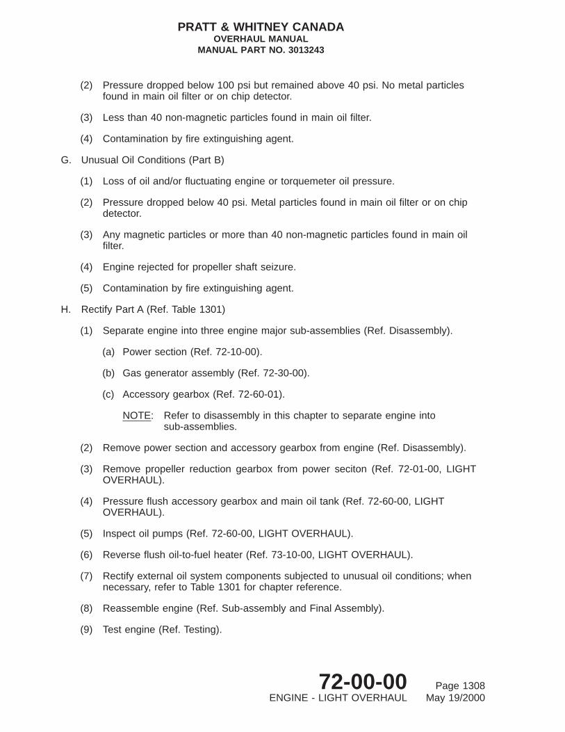
(2) Pressure dropped below 100 psi but remained above 40 psi. No metal particlesfound in main oil filter or on chip detector.
(3) Less than 40 non-magnetic particles found in main oil filter.
(4) Contamination by fire extinguishing agent.
G. Unusual Oil Conditions (Part B)
(1) Loss of oil and/or fluctuating engine or torquemeter oil pressure.
(2) Pressure dropped below 40 psi. Metal particles found in main oil filter or on chipdetector.
(3) Any magnetic particles or more than 40 non-magnetic particles found in main oilfilter.
(4) Engine rejected for propeller shaft seizure.
(5) Contamination by fire extinguishing agent.
H. Rectify Part A (Ref. Table 1301)
(1) Separate engine into three engine major sub-assemblies (Ref. Disassembly).
(a) Power section (Ref. 72-10-00).
(b) Gas generator assembly (Ref. 72-30-00).
(c) Accessory gearbox (Ref. 72-60-01).
NOTE: Refer to disassembly in this chapter to separate engine intosub-assemblies.
(2) Remove power section and accessory gearbox from engine (Ref. Disassembly).
(3) Remove propeller reduction gearbox from power seciton (Ref. 72-01-00, LIGHTOVERHAUL).
(4) Pressure flush accessory gearbox and main oil tank (Ref. 72-60-00, LIGHTOVERHAUL).
(5) Inspect oil pumps (Ref. 72-60-00, LIGHT OVERHAUL).
(6) Reverse flush oil-to-fuel heater (Ref. 73-10-00, LIGHT OVERHAUL).
(7) Rectify external oil system components subjected to unusual oil conditions; whennecessary, refer to Table 1301 for chapter reference.
(8) Reassemble engine (Ref. Sub-assembly and Final Assembly).
(9) Test engine (Ref. Testing).
PRATT & WHITNEY CANADAOVERHAUL MANUAL
MANUAL PART NO. 3013243
72-00-00 Page 1308ENGINE - LIGHT OVERHAUL May 19/2000

I. Rectify Part B
(1) Refer to Table 1303 for chapter reference and rectification of external oil systemcomponents.
(2) Separate engine into three engine major sub-assemblies (Ref. Disassembly).
(a) Power section (Ref. 72-10-00).
(b) Gas generator assembly (Ref. 72-30-00).
(c) Accessory gearbox (Ref. 72-60-01).
NOTE: Engine must be completely disassembled except for compressor rotor;No. 1 and No. 2 main bearings must be removed from compressorrotor for cleaning.
(3) Disassemble power section (Ref. Disassembly); rectify for unusual oil conditions onall assemblies removed (72-10-00, LIGHT OVERHAUL, Table 1301).
(4) Disassemble gas generator assembly (Ref. Disassembly); rectify for unusual oilconditions on all assemblies removed (Ref. 72-30-00, LIGHT OVERHAUL, Table1301).
(5) Disassemble accessory gearbox (Ref. Disassembly), rectify for unusual oilconditions on all assemblies removed (Ref. 72-60-00, LIGHT OVERHAUL, Table1301).
7. Contamination by Fire Extinguishing Agents
A. General
Fire extinguishing agents or compounds, of which sodium bicarbonate, potassiumbicarbonate and bromotrifluoromethane are the most common, can result in corrosiveattacks on both hot and cold section components. The severity of the corrosive attack islargely dependent upon the temperature to which the chemicals are exposed withinthe engine.
NOTE: Engines returned to an overhaul facility because of contamination by fireextinguishing agents should be washed internally and externally prior toremoval from airframe (Ref. 72-00-00, Maintenance Manual, P/N 3013242).
B. Engines Contaminated by Fire Extinguishing Agents
(1) Where fires have been external, or have been confined to burner and turbine gaspath, and overtemperature limits have not been exceeded, carry out light overhaulprocedures following.
(2) Where overtemperature limits have been exceeded and fire extinguishing agentcontamination is present, carry out light overhaul procedures Subpara. 4. andfollowing.
PRATT & WHITNEY CANADAOVERHAUL MANUAL
MANUAL PART NO. 3013243
72-00-00 Page 1309ENGINE - LIGHT OVERHAUL May 19/2000

C. Removal of Residual Deposits and Corrosion Repair
(1) Remove engine from container (Ref. Storage).
(2) Remove externals from engine and separate into following major subassemblies(Ref. Disassembly).
(a) Power section (Ref. 72-01-00).
(b) Gas generator assembly (Ref. 72-30-00).
(c) Accessory gearbox (Ref. 72-60-00).
(3) Separate power section into subassemblies (Ref. 72-01-00).
(4) Disassemble gas generator assembly (Ref. 72-30-00).
(5) Disassemble accessory gearbox as required (Ref. 72-60-00).
(6) Conduct light overhaul for contamination by fire extinguishing agents on eachsubassembly as outlines in appropriate chapter.
(7) If oil system contamination is suspected, treat as for unusual oil conditions (Ref.Subpara. E. preceding).
8. Power Section
A. If a power section is returned to an overhaul facility after unscheduled removal, refer to72-01-00 for Light Overhaul procedures.
9. Engine Components
A. General
If any of the following engine components are returned to an overhaul facility afterunscheduled removal, refer to LIGHT OVERHAUL in Chapter 72-30-00 and those listedin Table 1302.
TABLE 1302, Light Overhaul Reference for Unscheduled Removal - Engine Components
Component Chapter
Compressor Turbine (Blade Shift) 72-50-02
Combustion Chamber Exit Duct (Small) 72-50-01
Combustion Chamber Exit Duct (Large) 72-50-01
Combustion Chamber Liner 72-40-01
PRATT & WHITNEY CANADAOVERHAUL MANUAL
MANUAL PART NO. 3013243
72-00-00 Page 1310ENGINE - LIGHT OVERHAUL May 19/2000
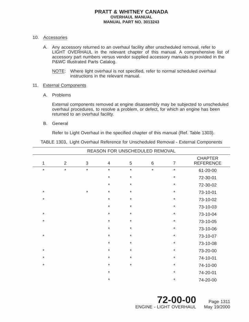
10. Accessories
A. Any accessory returned to an overhaul facility after unscheduled removal, refer toLIGHT OVERHAUL in the relevant chapter of this manual. A comprehensive list ofaccessory part numbers versus vendor supplied accessory manuals is provided in theP&WC Illustrated Parts Catalog.
NOTE: Where light overhaul is not specified, refer to normal scheduled overhaulinstructions in the relevant manual.
11. External Components
A. Problems
External components removed at engine disassembly may be subjected to unscheduledoverhaul procedures, to resolve a problem, or defect, for which an engine has beenreturned to an overhaul facility.
B. General
Refer to Light Overhaul in the specified chapter of this manual (Ref. Table 1303).
TABLE 1303, Light Overhaul Reference for Unscheduled Removal - External Components
REASON FOR UNSCHEDULED REMOVAL
1 2 3 4 5 6 7CHAPTER
REFERENCE
* * * * * * * 61-20-00
* * * 72-30-01
* * * 72-30-02
* * * * * 73-10-01
* * * * 73-10-02
* * * 73-10-03
* * * * 73-10-04
* * * * 73-10-05
* * * 73-10-06
* * * * 73-10-07
* * * 73-10-08
* * * * 73-20-00
* * * * 74-10-01
* * * * 74-10-00
* * 74-20-01
* * 74-20-00
PRATT & WHITNEY CANADAOVERHAUL MANUAL
MANUAL PART NO. 3013243
72-00-00 Page 1311ENGINE - LIGHT OVERHAUL May 19/2000

TABLE 1303, Light Overhaul Reference for Unscheduled Removal - ExternalComponents (Cont’d)
REASON FOR UNSCHEDULED REMOVAL
1 2 3 4 5 6 7CHAPTER
REFERENCE
* * * 75-30-00
* * * 76-10-00
* * * 77-20-01
* * * * 79-20-01
* * * * 79-20-04
* * * * 79-20-05
* * * * * 79-20-02
* * * 79-20-03
LEGEND:
1 Returned from Maintenance Facility
2 Overspeed
3 Unusual Oil Conditions
4 Immersion in Water
5 Dropped Engine
6 Sudden Stoppage
7 Fire extinguishing agent contamination
12. Testing
After completing light overhaul, engine must be tested in accordance with proceduresdescribed in Testing Section of this chapter.
After completing light overhaul of power sections, install in a slave gas generator assembly(Ref. Final Assembly) and test (Ref. Testing).
PRATT & WHITNEY CANADAOVERHAUL MANUAL
MANUAL PART NO. 3013243
72-00-00 Page 1312ENGINE - LIGHT OVERHAUL May 19/2000