bva pr & pw series manual
TRANSCRIPT

8/14/2019 BVA PR & PW Series Manual
http://slidepdf.com/reader/full/bva-pr-pw-series-manual 1/8

8/14/2019 BVA PR & PW Series Manual
http://slidepdf.com/reader/full/bva-pr-pw-series-manual 2/8
2
!
This is the safety alert symbol. It is used to alert you to potential personal injury hazards. Obey all safety messages that
follow this symbol to avoid possible injury or death.
• Study, understand, and follow all
instructions provided with and on this
device before use.
• All WARNING statements must be
carefully observed to help prevent
personal injury.
• No alteration shall be made to this
device.• Always wear protective gear when
operating hydraulic equipment.• Keep hydraulic equipment away from
flames and heat. Hydraulic fluid canignite and burn. Do not operate if leaks are detected.
• Crush Hazard. Keep hands andfeet away from loading area. Avoidpinch points or crush points that canbe created by the load or parts of cylinder.
• To avoid crushing and related injuries:NEVER work on, under or arounda lifted load before it is properlysupported by appropriate mechanicalmeans. Never rely on hydraulicpressure alone to support load.
! WARNING
HYDRAULIC CYLINDERS• The user must be a qualified operator familiar with the
correct operation, maintenance, and use of cylinders. Lack of knowledge in any of these areas can lead to personal injury.
• Do not exceed rated capacity of the cylinder or any equipmentin the system.
• Burst hazard exists if hose or connection pressure exceedsrated pressure.
• Inspect cylinder, hoses and connections before each use toprevent unsafe conditions from developing. Do not use if they are damaged, altered or in poor condition. Do not use acylinder with bent or damaged coupler or damaged threads.
• Use gauge or other load measuring instrument to verify load.• Do not subject the cylinder to shock loads.• Never attempt to disconnect hydraulic connections under
pressure.• Use only approved accessories and approved hydraulic fluid.• Never attach ANY component not authorized by manufacturer.• Never use other than factory provided and/or authorized
fasteners.
• Under certain conditions, the use of an extension with ahydraulic cylinder may not be advisable and could presenta dangerous condition.
• Cylinder must be on a stable base which is able to supportthe load while pushing or lifting. Ensure cylinder is fully
engaged into/onto adapters, extension accessories.• Use shims, friction material or constraints to prevent slippage
of the base or load.• Distribute the load evenly across
the entire saddle surface. Do notoff-center loads on a cylinder.The load can tip or the cylinder can “kick out”.
• This device is not suitable for use as support device! As theload is lifted, use blocking and cribbing to guard against afalling load.
• All personnel must be clear before lowering.• Never try to disassemble a hydraulic cylinder, refer repairs
to qualified, authorized personnel.
HYDRAULIC HOSES & FLUID TRANSMISSION LINES
• Avoid short runs of straight line tubing. Straight line runsdo not provide for expansion and contraction due topressure and/or temperature changes.
• Reduce stress in tube lines. Long tubing runs should besupported by brackets or clips. Before operating the pump,tighten all hose connections with proper tools. Do notovertighten. Connections should only be tightened securelyand leak-free. Overtightening can cause premature threadfailure or high pressure fittings to burst.
• Should a hydraulic hose ever rupture, burst or need to bedisconnected, immediately shut off the pump and releaseall pressure. Never attempt to grasp a leaking pressurizedhose with your hands. The force of escaping hydraulic fluidcan inflict injury.
• Do not subject the hose to potential hazard such as fire,
sharp objects, extreme heat or cold, or heavy impact.• Do not allow the hose to kink, twist, curl, crush, cut or bend
so tightly that the fluid flow within the hose is blocked or reduced. Periodically inspect the hose for wear.
• Do not pull, position or move setup by the hose.• Hose material and coupler seals must be compatible with
hydraulic fluid used. Hoses also must not come in contactwith corrosive materials such as battery acid, creosote-impregnated objects and wet paint. Never paint a coupler or hose.
• FAILURE TO HEED THESE WARNINGS MAY RESULT IN
PERSONAL INJURY AS WELL AS PROPERTY DAMAGE.
Center load on cylinder
Save these instructions. For your safety, read and understand the information contained within. The owner and operator shall
have an understanding of this device and safe operating procedures before attempting to use this device. Instructions and safety
information shall be conveyed in operator's native language before use of this device is authorized. Make certain that the operator
thoroughly understands the inherent dangers associated with the use and misuse of the product. If any doubt exists as to the safe
and proper use of this product as outlined in this factory authorized manual, remove from service immediately.
Inspect before each use. It is recommended that, prior to each use, an inspection be done by qualified personnel and that any
missing or damaged parts be replaced with factory authorized replacement parts only. Any valve that appears to be damaged in
any way, is worn, leaking or operates abnormally shall be removed from service immediately until such time as repairs can be
made. Any valve that has been or suspected to have been subject to a shock load (a load dropped suddenly, causing the systempressure to exceed 10,000 PSI), shall be removed from service immediately until checked by qualified personnel. Owners and
operators of this equipment shall be aware that the use and subsequent repair of this equipment may require special training
and knowledge.

8/14/2019 BVA PR & PW Series Manual
http://slidepdf.com/reader/full/bva-pr-pw-series-manual 3/8
PRODUCT DESCRIPTIONBVA Manual Control Valves are designed and manufactured for safe hydraulic operation to 10,000 psi. The pump mounted valves,
models PW2, PW3, PW4 and PW43L are specifically designed for use with BVA pumps only; Where the remote valve models
PR33 and PR43C are for remote hydraulic system control.
Always secure threaded port connections with non-hardening pipe thread compound. Take care not to introduce
compound into port orifices.
WARNING: To reduce the risk of personal injury and/or property damage, ensure that the rated working pressure of each
pressurized attachment be equal to or greater than the rated working pressure developed by the hydraulic pump.
BEFORE USE1. Before using this product, read the owner's manual completely and familiarize yourself thoroughly with the product, its components
and recognize the hazards associated with its use.
2. Verify that the product and the application are compatible. If in doubt, call BVA Hydraulics Technical Service (888) 332-6419.
3. Inspect before each use. Do not use if broken, leaking or damaged components are noted.
4. Replace worn or damaged parts with BVA Hydraulics authorized replacement parts only.
5. Use adequate eye protection when operating or near this device.
6. Ensure method of confirming load is accurate and working properly. Have gauge or load cell accuracy verified by qualified
personnel on a yearly basis.
SET UP1. For model PW2, PW3, PW4 & PW43L: Install the valve on BVA pump using gasket and hardware provided.
If you are not trained and familiar with installing a valve, please have an authorized BVA service center to perform this
procedure.
2. Connect and secure hoses, cylinders, fittings, gauges and pump etc. noting that the proper ports are connected.
3. Check for leaks in system.
Use an approved, high-grade pipe sealant to seal all hydraulic connections. When using teflon tape, never apply the tape
over ends of fittings where it can be torn loose and get into the hydraulic system.
OPERATION1. Place valve handle in proper position before starting pump. Tandem centered valves should be in "neutral" position; Close
centered valves should be in a position which will ensure a safe start up when the pump is started.
2. Valve equipped with positive locking feature, model PW43L will not permit movement of the load when the handle is moved
between positions. Valves not equipped with this feature will lower or drop the load during handle movement. The amount of
loss or load movement will depend on the speed of the handle movement between detent positions.
Note: All the valves are either tandem or closed center. Tandem centered valves allow oil to flow from the pump to tank when
in the NEUTRAL position. Closed centered valves block the flow of oil from the pump when in the NEUTRAL position.
MAINTENANCE1. Inspect hoses and connections daily. Replace damaged components immediately with BVA Hydraulics parts only.
2. Tighten connections as needed. Use pipe thread sealing compound when servicing connections.
3. Always use clean, approved hydraulic fluid and change as recommended or sooner if the fluid becomes contaminated (never
exceed 400 hours). Follow pump manufacturers instructions for changing and adding hydraulic fluid. Use only good quality
hydraulic fluid. We recommend Mobil DTE13M or equivalent when using with hand pump or air pump; BVA Hydraulics Oil (F01)
or equivalent when using with electric pump. Never use brake fluid, transmission fluid, turbine oil, motor oil, alcohol, glycerin
etc. Use of other than good quality hydraulic oil will void warranty and damage the cylinder, pump, hose etc.
Storage
When unit would be stored for long period, disconnect all hydraulic lines to prevent accidental operation. Wipe the unit clean.
Store in a clean, dry environment.
TROUBLE SHOOTING1. System will not build pressure.
a. Check pressure setting of pump, see pump's service instruction.
b. Check and tighten all hydraulic connections.
c. If trouble is not corrected, remove cylinder and hoses from the valve, place a gauge directly in valve port A and turn valve
to advance position. If no pressure developed, the unit should be taken to service center. If pressure develops, the cylinder
or connections are the problem.
2. Cylinder will not hold load. This is an indication of worn or damaged seals. Unit must be replaced/repaired by service center.
3
!
!
!
!

8/14/2019 BVA PR & PW Series Manual
http://slidepdf.com/reader/full/bva-pr-pw-series-manual 4/8
4
Valve
Location/
Operation
Valve
Type
Used
with
Cylinder
Model Hydraulic Symbol Schematic Flowpath
Advance Hold Retract
Remote
Mounted,
Manual
3-way,
3-position,
Tandem
Center
Single-
Acting PR33
4-way,
3-position,
Closed
Center
Double-
ActingPR43C
Pump
Mounted,
Manual
3-way,
2-position
Single-
ActingPW2
3-way,
3-position,
Tandem
Center
Single-
ActingPW3
4-way,
3-position,
Tandem
Center
Double-
ActingPW4
4-way,
3-position,
Tandem
Center,
Locking
Double-
ActingPW43L
MANUAL VALVE DIAGRAM

8/14/2019 BVA PR & PW Series Manual
http://slidepdf.com/reader/full/bva-pr-pw-series-manual 5/8
5
Note: Not all components of the valve are replacement items, but are illustrated as a convenient
reference of location and position in the assembly sequence.
PR33-M0
rev 10/07
MODELS: PR33 & PR43C
Manual Control Valves
Service Parts
SFA Companies 10939 N. Pomona Ave. Kansas City, MO 64153
Tel: 888-332-6419 * Fax: 816-891-6599
E-mail: [email protected] Website: www.bvahydraulics.com
Item Part No. Description Qty.
1 E05-6-1002-107 Cap Valve D44x25.4 1
2 649-1-0095-305 Socket Head Screw
3/8”-16UNCx1.5L
4
3 * Spring D6.1xD1x13 1
4 * Steel Ball, 1/4” 1
5 E05-6-1003-109 Valve Bonnet
63.5x63.5x31.8
1
6 * O-ring, D3.5x44.45 1
7 * O-ring, D1.8x15.8 1
8 611-3-0200-106 Washer, Thrust 1
9 622-6-0200-109 Bearing, Thrust 1
10 E05-3-1005-105 (for PR33)
D09-3-1006-106 (for PR43C)
Rotor Assembly 1
11 E05-4-1001-103
(PR33, 2 pc. only)
Shear Seal
Assembly
3
a N/A Shear Seal
D14.22x14.7
1
b * Back-up Ring
D8.1xD11x1.2T
1
c * O-ring D8x1.8x11.6 1
12 * (PR33, 2 pc. only) Spring Washer
25TxD11.7xD18.85
3
13 D09-6-1025-108 Valve Block 1
14 D05-6-1001-106
(PR33, 3pc. only)
Hex Socket Plug,
3/8NPTxH19x23L
4
15 641-1-0100-104 Socket Head Screw
M10x1.5x10
1
16 E05-6-1009-101 Handle, D10x98.5 1
17 E05-6-1008-109 Knob, D30 1
18 601-4-0060-101 Roll Pin, D16x12 1
19 H18-6-8104-106
(for PR33 only)
Hex Socket Pipe
Plug 3/8NPT
1
(*) D09-3-9914-101 Repair Kit 1
1
2
3
4
5
6
7
8
9
10
11a
11b
11c
12
13
14
14
16
17
18

8/14/2019 BVA PR & PW Series Manual
http://slidepdf.com/reader/full/bva-pr-pw-series-manual 6/8
6
Note: Not all components of the valve are replacement items, but are illustrated as a convenient
reference of location and position in the assembly sequence.
PR33-M0
rev 10/07
MODEL: PW2
Manual Control Valve
Service Parts
SFA Companies 10939 N. Pomona Ave. Kansas City, MO 64153
Tel: 888-332-6419 * Fax: 816-891-6599
E-mail: [email protected] Website: www.bvahydraulics.com
Item Part No. Description Qty.
1 D09-6-1011-107 Valve Block 1
2 D09-6-2001-109 Unloading Pin 1
3 512-2-0110-107 Spring 1
4 E05-6-8006-100 Hollow Set Screw 15 H20-6-6008-102 Bushing 1
6 H39-5-8104-103 Hex Socket Plug 1
7 * Gasket 1
8 * E-clip 1
9 D05-6-1001-106 Hex Socket Plug,
3/8NPTxH19x23L
1
10 * O-ring 1
11 D09-6-1013-101 Unloading Pin 1
12 D09-6-1012-109 Rotor shaft 1
2
56
1
9
11
10
19
7
8
12
13
14
15
16
17
18
20a
20b
20c20
8/14/2019 BVA PR & PW Series Manual
http://slidepdf.com/reader/full/bva-pr-pw-series-manual 7/8
7
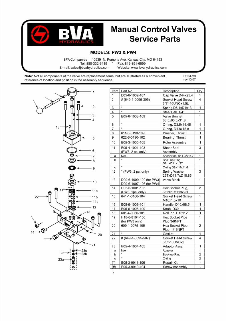
Note: Not all components of the valve are replacement items, but are illustrated as a convenient
reference of location and position in the assembly sequence.
PR33-M0
rev 10/07
MODELS: PW3 & PW4
Manual Control Valves
Service Parts
SFA Companies 10939 N. Pomona Ave. Kansas City, MO 64153
Tel: 888-332-6419 * Fax: 816-891-6599
E-mail: [email protected] Website: www.bvahydraulics.com
Item Part No. Description Qty.
1 E05-6-1002-107 Cap Valve D44x25.4 1
2 # (649-1-0095-305) Socket Head Screw
3/8”-16UNCx1.5L
4
3 * Spring D6.1xD1x13 1
4 * Steel Ball, 1/4” 15 E05-6-1003-109 Valve Bonnet
63.5x63.5x31.8
1
6 * O-ring, D3.5x44.45 1
7 * O-ring, D1.8x15.8 1
8 611-3-0190-109 Washer, Thrust 1
9 622-6-0190-102 Bearing, Thrust 1
10 E05-3-1005-105 Rotor Assembly 1
11 E05-4-1001-103
(PW3, 2 pc. only)
Shear Seal
Assembly
3
a N/A Shear Seal D14.22x14.7 1
b * Back-up Ring
D8.1xD11x1.2T
1
c * O-ring D8x1.8x11.6 112 * (PW3, 2 pc. only) Spring Washer
25TxD11.7xD18.85
3
13 D09-6-1009-100 (for PW3)
D09-6-1007-106 (for PW4)
Valve Block 1
14 D05-6-1001-106
(PW3, 1pc. only)
Hex Socket Plug,
3/8NPTxH19x23L
2
15 641-1-0100-104 Socket Head Screw
M10x1.5x10
1
16 E05-6-1009-101 Handle, D10x98.5 1
17 E05-6-1008-109 Knob, D30 1
18 601-4-0060-101 Roll Pin, D16x12 1
19 H18-6-8104-106
(for PW3 only)
Hex Socket Pipe
Plug 3/8NPT
1
20 609-1-0075-105 Hex Socket PipePlug 1/16NPT
2
21 * Gasket 1
22 # (649-1-0095-507) Socket Head Screw
3/8"-16UNCx2
4
23 E05-4-1004-105 Adaptor Assy. 1
a N/A Adaptor 1
b * Back-up Ring 2
c * O-ring 2
(*) E05-3-9911-106 Repair Kit -
(#) E05-3-9910-104 Screw Assembly -
1
2
3
4
5
6
7
8
9
10
11a
11b
11c
12
13
18
11
1420
21
22
23a
23b
23c23

8/14/2019 BVA PR & PW Series Manual
http://slidepdf.com/reader/full/bva-pr-pw-series-manual 8/8
8
LIFETIME LIMITED WARRANTY
BVA Hydraulics®, represented in the United States by Shinn Fu Company of America, Inc. [“SFA”] warrants this
product to be free from defects in material and workmanship for the life of the product as long as the original
purchaser owns the product. The warranty is non-transferable and is subject to the terms, exclusions, and limitations
described below:
• Damaged components, including but not limited to bent rams, dented or crushed cylinder walls, broken welds or
couplers as well as worn out seals, o-rings and springs are the result of misuse and not covered by warranty and
BVA Hydraulics will not provide any warranty credit for such damaged components.
• This warranty does not cover ordinary wear and tear, overloading, alterations (including repairs or attempted
repairs not performed by BVA Hydraulics or one of its authorized personnel), improper fluid use, or use of the
product in any manner for which the product was not intended or the use of which is not in accordance with the
instructions or warnings provided with the product.
• In the unlikely event that a BVA Hydraulics product fails due to material defect in workmanship, you may contact
SFA for disposition. In such cases, the customer’s sole and exclusive remedy for any breach or alleged breach
of warranty is limited to the repair or replacement of the defective product.
• Under no circumstances is BVA Hydraulics liable for any consequential or incidental damage or loss
whatsoever.
• THIS WARRANTY IS LIMITED TO NEW PRODUCTS SOLD THROUGH AUTHORIZED DISTRIBUTORSAND OTHER CHANNELS DESIGNATED BY BVA HYDRAULICS. NO AGENT, EMPLOYEE OR OTHER
REPRESENTATIVE OF BVA HYDRAULICS IS AUTHORIZED TO MODIFY THIS WARRANTY.
• THE FOREGOING IS EXCLUSIVE AND IS IN LIEU OF ALL OTHER EXPRESS AND IMPLIED WARRANTIES,
INCLUDING BUT NOT LIMITED TO THE IMPLIED WARRANTIES OF MERCHANTABILITY AND FOR A
FITNESS FOR A PARTICULAR PURPOSE.
• Components not manufactured by BVA Hydraulics including certain motor systems, gasoline engines, and others
are not covered by this warranty and instead are covered by the manufacturer’s separate manufacturer’s warranty
provided in the package.
• BVA Hydraulics’ liability in all cases is limited to, and will not exceed the purchase price paid for the product.
SFA Companies
10939 N. Pomona Ave. Kansas City, MO 64153
Tel: 888-332-6419
E-mail: [email protected]