pv grid-tied residential inverters - pv...
TRANSCRIPT
97-600100-01-A02
PV Grid-tied Residential InvertersINSTALLATION & OPERATION MANUAL

i
Preface
PV Powered
PV Powered designs, manufactures, and markets the solar power industry’s most reliable photovoltaic solar inverter solutions. We’ve assembled a highly experienced solar power electronics design team. Our vision is to spur the widespread adoption and success of solar power, by assisting our distributors, dealers and installers in this dynamic market while ensuring that our products are the best supported, easiest to install, and most reliable solar inverters in the industry. Our innovative approach to performance monitoring provides secure and easy access to system performance and inverter status over the Internet.
Contact Information
PV Powered, Inc. PO Box 7348 Bend, OR 97708
Tel: 541-312-3832 Technical Support: 1-877-312-3832 Fax: 541-383-2348
www.pvpowered.com email: [email protected]
Document Copyright
PV Powered Grid-tied Inverters Installation and Operation Manual ©2009 PV Powered. All rights reserved. This manual may not be reproduced or distributed without written permission from PV Powered.
PR
EFA
CE
ii
Safety Information and Conventions
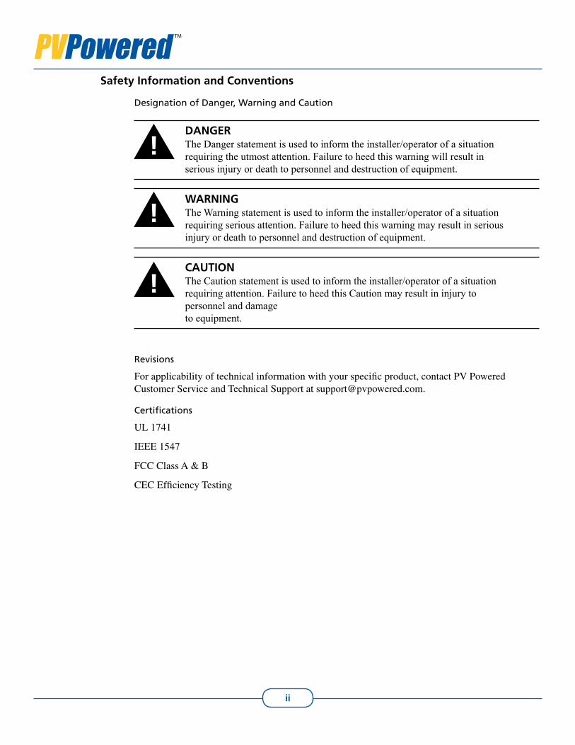
Designation of Danger, Warning and Caution
DANGERThe Danger statement is used to inform the installer/operator of a situation requiring the utmost attention. Failure to heed this warning will result in serious injury or death to personnel and destruction of equipment.
WARNINGThe Warning statement is used to inform the installer/operator of a situation requiring serious attention. Failure to heed this warning may result in serious injury or death to personnel and destruction of equipment.
CAUTIONThe Caution statement is used to inform the installer/operator of a situation requiring attention. Failure to heed this Caution may result in injury to personnel and damage to equipment.
Revisions
For applicability of technical information with your specific product, contact PV Powered Customer Service and Technical Support at [email protected].
Certifications
UL 1741
IEEE 1547
FCC Class A & B
CEC Efficiency Testing
!
!
!
iii
Grid-tied Residential InvertersInstallation and Operation Manual
Acronyms and Abbreviations
AC Alternating Current
ANSI American National Standards Institute
AWG American Wire Gage
CEC California Energy Commission
CPU Controlled Processing Unit
DC Direct Current
EGC Equipment Grounding Conductor
FCC Federal Communications Commission (US)
GEC Grounding Electrode Conductor
GFI Ground Fault Interrupt
IEEE Institute of Electrical and Electronics Engineers
LED Light-Emitting Diode
LOTO Lockout Tagout
LP Low Power
MPPT Maximum Power Point Tracking
NEMA National Electrical Manufacturers Association
NEC National Electric Code
NFPA National Fire Protection Association
Nm A unit of torque
PLL Phase Lock Loop
PPE Personal Protective Equipment
PV Photovoltaic
STC Standard Test Condition
UL Underwriters Laboratory
VAC Voltage Alternating Current
VDC Voltage Direct Current
VFD Vacuum Fluorescent Display
VOC Voltage Open Circuit
VOC_TC Voltage Open Circuit, Temperature Coefficient

iv
Table of Contents
Preface ..................................................................................................................................iSafety Information and Conventions .................................................................................. iiAcronyms and Abbreviations ............................................................................................ iii1. Introduction and Safety ...................................................................................................1
1.1 Introduction ............................................................................................................11.2 General Safety ........................................................................................................11.3 FCC Compliance ....................................................................................................2
2. Planning ...........................................................................................................................32.1 Selecting a Location for the Inverter ......................................................................32.2 Guidelines for Mounting the Inverter ....................................................................3
3. Installation .......................................................................................................................53.1 Mounting and Anchoring the Inverter ....................................................................53.2 Electrical Connections ............................................................................................7
4. Operations......................................................................................................................174.1 Start up Procedures ...............................................................................................174.2 Inverter Front Panel Status Indicators ..................................................................17
5. Troubleshooting .............................................................................................................205.1 LED Status ............................................................................................................205.2 Displayed Fault Codes ..........................................................................................215.3 Fault Codes ...........................................................................................................23
Appendix A - Specifications ..............................................................................................24Appendix B - Dimensions .................................................................................................28
B.1 Schematics for PVP1100W, PVP2000W, PVP2500W, PVP2800W, PVP3000W, and PVP3500W Inverter Cabinet ....................................................28
B.2 Schematics for PVP4600W, PVP4800W, and PVP5200W Inverter Cabinet ......29Limited Warranty ...............................................................................................................31Return Procedure ...............................................................................................................33Index ..................................................................................................................................34
TAB
LE O
F C
ON
TEN
TS
v
List of Figures and TablesFigure 2-1 View of the Inverter’s Interior Components .....................................................4
Figure 3-1 Small Mounting Bracket ...................................................................................5Figure 3-2 Large Mounting Bracket ...................................................................................6Figure 3-3 Inside Screw - Below the Power Board ............................................................6Figure 3-4 Inverter and PV System Disconnectwith Mounting Bracket in Place ..............7Table 3-1 Required Branch Circuit Protection...................................................................8Table 3-2 Inverter Voltage Frequency Limits ....................................................................8Figure 3-5 Communications, AC and DC Ports ..................................................................9Table 3-3 Grounding Electrode Sizing ............................................................................10Figure 3-6 System Block Diagram Showing Single-Point Ground ..................................11Figure 3-7 Ground Fault Message ....................................................................................12Figure 3-8 AC and PV Grounding ....................................................................................12Figure 3-9 AC Wiring for the Line 1, Line 2 and Ground Conductors .............................13Table 3-4 PV Open Circuit Voltages ................................................................................14Figure 3-10 Positive and Negative GFI Jumpers ..............................................................15Figure 3-11 Power Board Connections .............................................................................16
Figure 4-1 Normal Startup Screens ..................................................................................19Figure 4-2 Running Screens .............................................................................................19
Figure 5-1 Faulted .............................................................................................................21Figure 5-2 Starting Up From a Faulted State ....................................................................21Figure 5-3 AC Voltage High/DC Voltage Low Fault ........................................................22Figure 5-4 Power Low Fault .............................................................................................22
Table 5-1 Fault Codes .......................................................................................................23
Table A-1 PVP1100 through PVP2800 Specifications .....................................................24Table A-1 (continued) PVP3000 through PVP5200 Specifications ...................................25Table A-2 Abnormal Specifications ..................................................................................26
Figure B-1 Side and Front Views of PVP1100W, PVP2000W, PVP2500W, PVP2800W, PVP3000W, and PVP3500W Inverter Cabinet ................................27
Figure B-2 Back and Bottom Views of PVP1100W, PVP2000W, PVP2500W, PVP2800W, PVP3000W, and PVP3500W Inverter Cabinet ................................28
Figure B-3 Side and Front Views of the PVP4600W, PVP4800W, and PVP5200W Inverter Cabinet .........................................................................29
Figure B-4 Back and Bottom Views of the PVP4600W, PVP4800W, and PVP5200W Inverter Cabinet .........................................................................30
1
1. Introduction and Safety
Introduction1.1
The PV Powered Grid-Tied Inverter is a utility interactive inverter for photovoltaic (PV) systems.
The inverter is tied to an electrical source provided by the local utility company as well as the PV system. The inverter contains everything needed to convert the DC energy generated by the PV array(s) into AC energy required to power a house.
This manual provides information necessary for the successful installation and use of the PV Powered Grid-Tied Inverter.
General Safety1.2
IMPORTANT SAFETY INSTRUCTIONS: This product has been engineered and manufactured to ensure your personal safety. Improper use may result in potential electrical shock or burns. Read and follow all instructions for installation, use and servicing of this product. Read all safety warnings before installing or operating the inverter.
NOTE: A locking tab has been designed into the PV Powered Grid-tied Inverter. Locking the inverter is the sole responsibility of the end user. Secure the lid to prevent unauthorized access or damage to the inverter.
SAVE THESE INSTRUCTIONS: This manual contains important instructions for the PV Powered Grid-Tied Inverter that must be followed during installation of the PV Powered Grid-Tied Inverter.
INSTRUCTIONS IMPORTANTES CONCERNANT LA SECURITÉ CONSERVER CES INSTRUCTIONS. CETTE NOTICE CONTIENT DES INSTRUCTIONS IMPORTANTES CONCERNANT LA SÉCURITÉ.
!CAUTION
All electrical installations should be done in accordance with local •electrical codes and the National Electrical Code (NEC), ANSI/NFPA 70.
Before connecting the inverter to the electrical utility grid, your utility •company must grant approval. Only qualified electricians should make the connection.
When exposed to light, PV arrays form electrical energy that creates a •potentially hazardous condition. To avoid this, completely cover the surface of all PV arrays with opaque (dark) material before wiring them.
The inverter contains no user-serviceable parts. Refer maintenance to •qualified service personnel.
INTR
OD
UC
TION
& S
AFE
TY
2
FCC Compliance1.3
The PV Powered Grid-Tied Inverters have been tested and found to pass FCC Class B radio interference standards with proper installation of the inverter. This is not a guarantee that there will be no interference at every installation. If you notice interference at your installation, try the following potential solutions:
Move or re-orient the affected device.• Increase the distance between the devices.• Connect the device to a different AC circuit.•
!CAUTIONRead all safety warnings and instructions before installing or operating the inverter.
3
2. Planning
Selecting a Location for the Inverter2.1
When choosing a location for the inverter, consider the following criteria:
The inverter is suitable for both indoor and outdoor installation; the inverter enclosure • has a NEMA 3R rating. The optimum location of the inverter is outside, shielded from direct exposure to sun-• light (i.e. not on the south facing side of the building). The heat sink temperature can exceed 158°F (70°C). The inverter should be installed so • that people can not touch the top of the unit. The inverter is designed and tested to produce maximum continuous output power • within the ambient temperature range of -15°F to 105°F (-25°C to 40°C).
Location and Clearances
The following clearances are recommended for proper placement of the inverter:
A minimum of 36 inches between the bottom of the inverter box and the ground.• A minimum of 12 inches above the heat sink.• Approximately one half inch of width clearance on the right and left sides of the in-• verter cabinet.
Visibility of the operating LEDs and display located at the top front of the inverter box should also be considered. Refer to Figure 2-1 for these within the inverter’s box.
If the inverter is installed in an enclosed space, adequate ventilation must be provided.
Guidelines for Mounting the Inverter 2.2
The inverter should be mounted vertically to a flat, solid surface such as strut, concrete, or wood siding. It should be located near the PV arrays to minimize the DC conductor length.
The bracket and paper mounting template provided make mounting the inverter quick and simple.
The small bracket:
Has a vertical row of screw holes down the center and is designed for a single-stud • mount. Refer to Figure 3-2.
The large bracket:
Has two top screw holes at either end of the large bracket, 16” apart which are designed • to match standard stud spacing. Refer to Figure 3-1.
The inverter also has an internal mounting screw. Refer to Figure 2-1 for the location of this screw.
PLA
NN
ING

4
!WARNINGBefore drilling holes to mount the inverter, verify that there are no electrical wires or plumbing in the area.
Figure 2-1 View of the Inverter’s Interior Components
Control Boardwith LED Lights
Transformer
Inductor
Power Board
Display
GFI Fuse Port
Mounting Screw
5
3. Installation
Mounting and Anchoring the Inverter3.1
After you have determined a suitable location for the inverter, the bracket is anchored to the wall stud(s).
Models PVP1100, PVP2000, PVP2500, PVP2800, PVP3000 and PVP3500
Locate a wall stud in the desired location and align the mounting bracket or paper 1. mounting template with the vertical row of screw holes over it for a single-stud mount. Mark the mounting holes ensuring holes C through F are directly over the single stud. VERIFY THE BRACKET IS LEVEL. Ensure points C through F are aligned with the 2. wall stud. Drill 1/8” pilot holes for the screws.
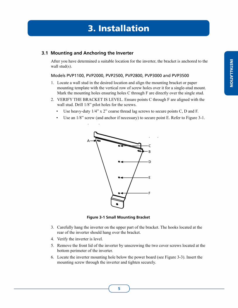
Use heavy-duty 1/4” x 2” coarse thread lag screws to secure points C, D and F. • Use an 1/8” screw (and anchor if necessary) to secure point E. Refer to Figure 3-1. •
Figure 3-1 Small Mounting Bracket
Carefully hang the inverter on the upper part of the bracket. The hooks located at the 3. rear of the inverter should hang over the bracket.Verify the inverter is level. 4. Remove the front lid of the inverter by unscrewing the two cover screws located at the 5. bottom perimeter of the inverter. Locate the inverter mounting hole below the power board (see Figure 3-3). Insert the 6. mounting screw through the inverter and tighten securely.
B
AC
D
E
F
INSTA
LLATIO
N
6
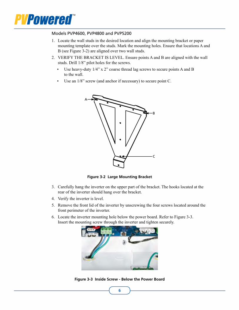
Models PVP4600, PVP4800 and PVP5200
Locate the wall studs in the desired location and align the mounting bracket or paper 1. mounting template over the studs. Mark the mounting holes. Ensure that locations A and B (see Figure 3-2) are aligned over two wall studs. VERIFY THE BRACKET IS LEVEL. Ensure points A and B are aligned with the wall 2. studs. Drill 1/8” pilot holes for the screws.
Use heavy-duty 1/4” x 2” coarse thread lag screws to secure points A and B • to the wall. Use an 1/8” screw (and anchor if necessary) to secure point C.•
Figure 3-2 Large Mounting Bracket
Carefully hang the inverter on the upper part of the bracket. The hooks located at the 3. rear of the inverter should hang over the bracket.Verify the inverter is level. 4. Remove the front lid of the inverter by unscrewing the four screws located around the 5. front perimeter of the inverter.Locate the inverter mounting hole below the power board. Refer to Figure 3-3. 6. Insert the mounting screw through the inverter and tighten securely.
Figure 3-3 Inside Screw - Below the Power Board
B
A
C
7
Grid-tied Residential InvertersInstallation and Operation Manual
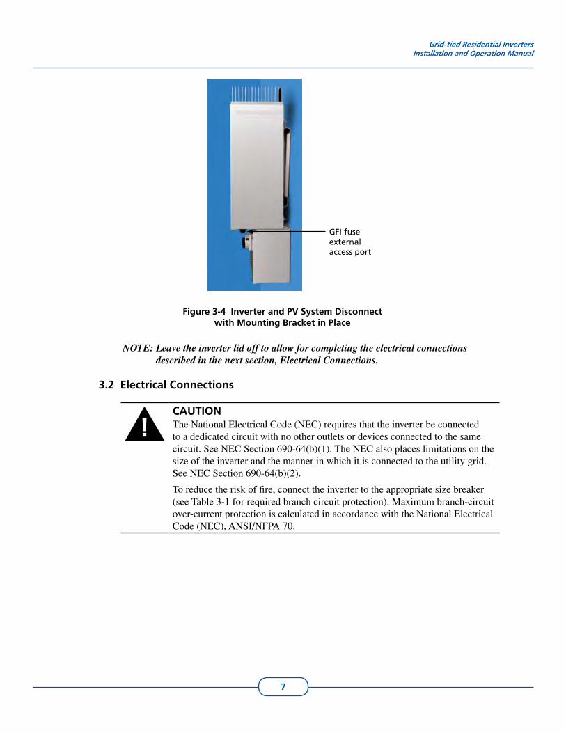
GFI fuse external access port
Figure 3-4 Inverter and PV System Disconnect with Mounting Bracket in Place
NOTE: Leave the inverter lid off to allow for completing the electrical connections described in the next section, Electrical Connections.
Electrical Connections3.2
!CAUTIONThe National Electrical Code (NEC) requires that the inverter be connected to a dedicated circuit with no other outlets or devices connected to the same circuit. See NEC Section 690-64(b)(1). The NEC also places limitations on the size of the inverter and the manner in which it is connected to the utility grid. See NEC Section 690-64(b)(2).
To reduce the risk of fire, connect the inverter to the appropriate size breaker (see Table 3-1 for required branch circuit protection). Maximum branch-circuit over-current protection is calculated in accordance with the National Electrical Code (NEC), ANSI/NFPA 70.
8
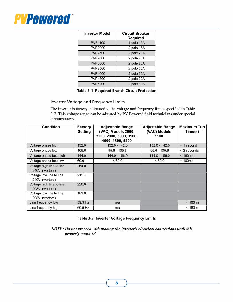
Inverter Model Circuit Breaker Required
PVP1100 1 pole 15APVP2000 2 pole 15APVP2500 2 pole 20APVP2800 2 pole 20APVP3000 2 pole 20APVP3500 2 pole 20APVP4600 2 pole 30APVP4800 2 pole 30APVP5200 2 pole 30A
Table 3-1 Required Branch Circuit Protection
Inverter Voltage and Frequency Limits
The inverter is factory calibrated to the voltage and frequency limits specified in Table 3-2. This voltage range can be adjusted by PV Powered field technicians under special circumstances.
Condition Factory Setting
Adjustable Range (VAC) Models 2000,
2500, 2800, 3000, 3500, 4600, 4800, 5200
Adjustable Range (VAC) Models
1100
Maximum Trip Time(s)
Voltage phase high 132.0 132.0 - 142.0 132.0 - 142.0 < 1 secondVoltage phase low 105.6 95.6 - 105.6 95.6 - 105.6 < 2 secondsVoltage phase fast high 144.0 144.0 - 156.0 144.0 - 156.0 < 160msVoltage phase fast low 60.0 < 60.0 < 60.0 < 160msVoltage high line to line (240V inverters)
264.0
Voltage low line to line (240V inverters)
211.0
Voltage high line to line (208V inverters)
228.8
Voltage low line to line (208V inverters)
183.0
Line frequency low 59.3 Hz n/a < 160msLine frequency high 60.5 Hz n/a < 160ms
Table 3-2 Inverter Voltage Frequency Limits
NOTE: Do not proceed with making the inverter’s electrical connections until it is properly mounted.
9
Grid-tied Residential InvertersInstallation and Operation Manual
!WARNINGElectrical connections must be completed in accordance with local electrical codes and the National Electrical Code (NEC), ANSI/NFPA 70. Use 12 AWG minimum, 90°C copper wire for all inverter electrical connections. Voltage drop as well as other considerations may dictate using larger wire sizes.
NOTE: To avoid an increase in AC voltage level, which may lead to nuisance faults, PV Powered recommends sizing the conductor for a drop of less than 2%.
!WARNINGEnsure the breaker in the main utility service panel is switched OFF before wiring the inverter. This breaker should be switched ON only after all wiring has been completed as described in this manual.
!WARNINGFollow the order listed below to wire the inverter. Failure to do so may result in hazardous voltages or disconnection of contacts.
IMPORTANT: When mounting the inverter outside, use rain-tight or wet-location conduit hubs that comply with the requirements in the Standard for Fittings for Conduit and Outlet Boxes, UL 514B.
NOTE: Terminal connections for the inverter are located inside the inverter on the circuit board at the bottom of the cabinet. The AC and DC terminals accept wires up to 6 AWG.
!CAUTIONThe DC/AC input and output circuits are isolated from the enclosure. The PV equipment grounding conductor (EGC), where required by Sections 690-41, 690-42, and 690-43 of the National Electric Code (NEC), ANSI/NFPA 70, is the responsibility of the installer. Failure to properly install the ground conductor for the PV equipment can result in exposed metallic surfaces becoming energized to the full potential of the PV array.
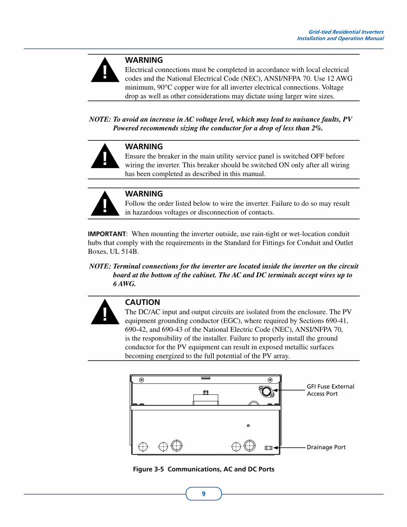
Figure 3-5 Communications, AC and DC Ports
GFI Fuse External Access Port
Drainage Port
10
Separation of Circuits
The lower part of the inverter circuit board is divided into three sections:
The left side is dedicated to the low voltage DC communications (PVM1010 data moni-1. toring module).The center is dedicated to the AC.2. The right side is dedicated to the DC. 3.
Each section has one to three knockouts. UL 1741 requires a straight run of conductor, with no loops or crossover to the other circuits (sections) and low voltage versus high voltage in each section (see Figure 3-5).
Left knockouts (up to the divider) are for low voltage communications only (PVM1010 1. Data Monitoring Module).Center knockouts are for AC.2. Right knockouts are for DC.3.
Grounding
A single-point ground conductor connection is located in the lower right-hand side of the inverter cabinet. This is where the DC grounding electrode conductor (GEC) is terminated. The AC equipment grounding conductor (EGC) is terminated next to the Line 1 and Line 2 connections on the circuit board.
The grounding lug is attached to the cabinet with a 10-32 bolt. The equipment ground connector or grounding lug is provided, utilizing the PV equipment and AC ground conductor. This is the only place the PV ground should be connected to the inverter.
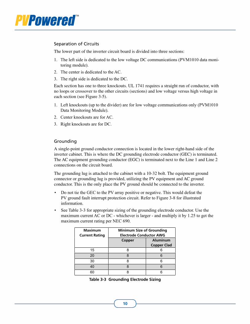
Do not tie the GEC to the PV array positive or negative. This would defeat the • PV ground fault interrupt protection circuit. Refer to Figure 3-8 for illustrated information. See Table 3-3 for appropriate sizing of the grounding electrode conductor. Use the • maximum current AC or DC - whichever is larger - and multiply it by 1.25 to get the maximum current rating per NEC 690.
Maximum Current Rating
Minimum Size of Grounding Electrode Conductor AWGCopper Aluminum
Copper Clad15 8 620 8 630 8 640 8 660 8 6
Table 3-3 Grounding Electrode Sizing
11
Grid-tied Residential InvertersInstallation and Operation Manual
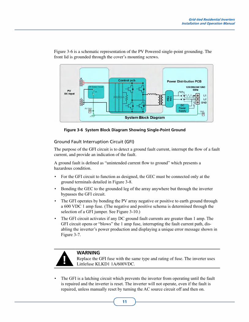
Figure 3-6 is a schematic representation of the PV Powered single-point grounding. The front lid is grounded through the cover’s mounting screws.
Page 1 of 1
8/21/2008file://C:\Documents and Settings\AlisonW\Desktop\LineBlock_Figure3.6edited.vsd
Figure 3-6 System Block Diagram Showing Single-Point Ground
Ground Fault Interruption Circuit (GFI)
The purpose of the GFI circuit is to detect a ground fault current, interrupt the flow of a fault current, and provide an indication of the fault.
A ground fault is defined as “unintended current flow to ground” which presents a hazardous condition.
For the GFI circuit to function as designed, the GEC must be connected only at the • ground terminals detailed in Figure 3-8. Bonding the GEC to the grounded leg of the array anywhere but through the inverter • bypasses the GFI circuit. The GFI operates by bonding the PV array negative or positive to earth ground through • a 600 VDC 1 amp fuse. (The negative and positive schema is determined through the selection of a GFI jumper. See Figure 3-10.) The GFI circuit activates if any DC ground fault• currents are greater than 1 amp. The GFI circuit opens or “blows” the 1 amp fuse, interrupting the fault current path, dis-abling the inverter’s power production and displaying a unique error message shown in Figure 3-7.
!WARNINGReplace the GFI fuse with the same type and rating of fuse. The inverter uses Littlefuse KLKD1 1A/600VDC.
The GFI is a latching circuit which prevents the inverter from operating until the fault • is repaired and the inverter is reset. The inverter will not operate, even if the fault is repaired, unless manually reset by turning the AC source circuit off and then on.
12
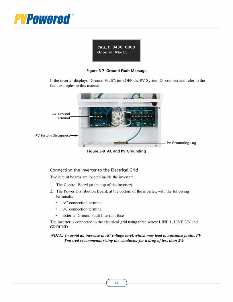
Figure 3-7 Ground Fault Message
If the inverter displays “Ground Fault”, turn OFF the PV System Disconnect and refer to the fault examples in this manual.
Figure 3-8 AC and PV Grounding
Connecting the Inverter to the Electrical Grid
Two circuit boards are located inside the inverter:
The Control Board (at the top of the inverter).1. The Power Distribution Board, at the bottom of the inverter, with the following 2. terminals:
AC connection terminal• DC connection terminal• External Ground Fault Interrupt fuse•
The inverter is connected to the electrical grid using three wires: LINE 1, LINE 2/N and GROUND.
NOTE: To avoid an increase in AC voltage level, which may lead to nuisance faults, PV Powered recommends sizing the conductor for a drop of less than 2%.
PV Grounding Lug
PV System Disconnect
AC Ground Terminal
13
Grid-tied Residential InvertersInstallation and Operation Manual
!WARNINGEnsure the main 240VAC (or 208VAC for the PVP2800 and PVP4600, or 120VAC for PVP1100) breaker at the circuit breaker panel is switched OFF before connecting to the AC terminal block.
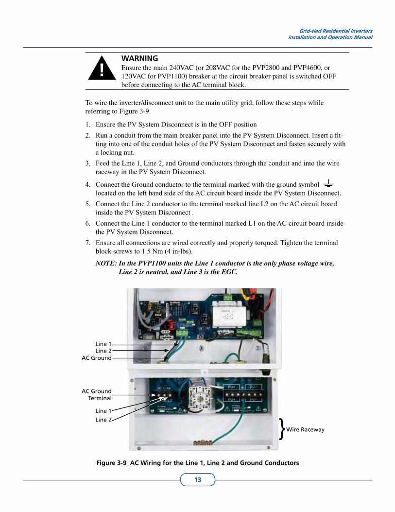
To wire the inverter/disconnect unit to the main utility grid, follow these steps while referring to Figure 3-9.
Ensure the PV System Disconnect is in the OFF position1. Run a conduit from the main breaker panel into the PV System Disconnect. Insert a fit-2. ting into one of the conduit holes of the PV System Disconnect and fasten securely with a locking nut.Feed the Line 1, Line 2, and Ground conductors through the conduit and into the wire 3. raceway in the PV System Disconnect.
Connect the Ground conductor to the terminal marked with the ground symbol 4. located on the left hand side of the AC circuit board inside the PV System Disconnect.Connect the Line 2 conductor to the terminal marked line L2 on the AC circuit board 5. inside the PV System Disconnect .Connect the Line 1 conductor to the terminal marked L1 on the AC circuit board inside 6. the PV System Disconnect. Ensure all connections are wired correctly and properly torqued. Tighten the terminal 7. block screws to 1.5 Nm (4 in-lbs).
NOTE: In the PVP1100 units the Line 1 conductor is the only phase voltage wire, Line 2 is neutral, and Line 3 is the EGC.
Figure 3-9 AC Wiring for the Line 1, Line 2 and Ground Conductors
Line 1Line 2
AC Ground
AC Ground Terminal
Wire Raceway}Line 1
Line 2
14
Connecting DC Wires and PV Panels
!WARNINGBefore proceeding with the DC wiring, completely cover the surface of all PV panels with dark material to avoid the production of electrical energy.
!WARNINGMake sure the grounding scheme and the PV panel voltage between the positive and the negative cable connectors of the PV panels are correct before connecting the panels to the DC terminal block on the power distribution board.
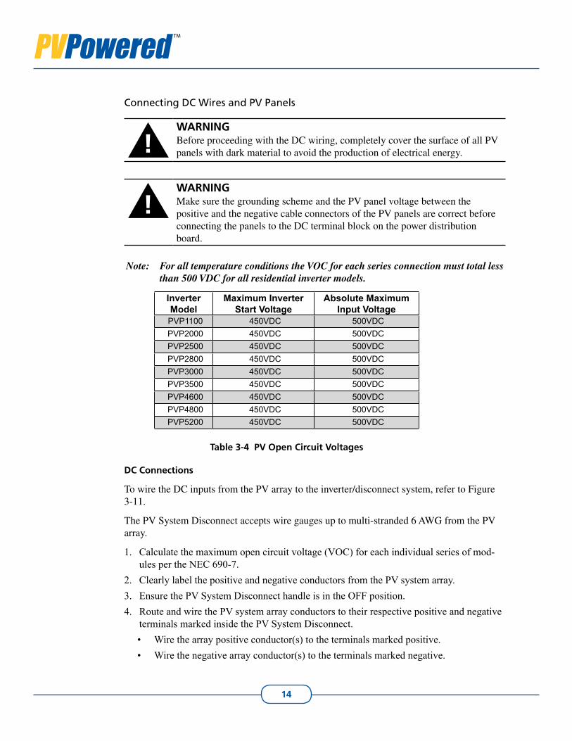
Note: For all temperature conditions the VOC for each series connection must total less than 500 VDC for all residential inverter models.
InverterModel
Maximum Inverter Start Voltage
Absolute Maximum Input Voltage
PVP1100 450VDC 500VDCPVP2000 450VDC 500VDCPVP2500 450VDC 500VDCPVP2800 450VDC 500VDCPVP3000 450VDC 500VDCPVP3500 450VDC 500VDCPVP4600 450VDC 500VDCPVP4800 450VDC 500VDCPVP5200 450VDC 500VDC
Table 3-4 PV Open Circuit Voltages
DC Connections
To wire the DC inputs from the PV array to the inverter/disconnect system, refer to Figure 3-11.
The PV System Disconnect accepts wire gauges up to multi-stranded 6 AWG from the PV array.
Calculate the maximum open circuit voltage (VOC) for each individual series of mod-1. ules per the NEC 690-7.Clearly label the positive and negative conductors from the PV system array.2. Ensure the PV System Disconnect handle is in the OFF position.3. Route and wire the PV system array conductors to their respective positive and negative 4. terminals marked inside the PV System Disconnect.
Wire the array positive conductor(s) to the terminals marked positive.• Wire the negative array conductor(s) to the terminals marked negative. •
15
Grid-tied Residential InvertersInstallation and Operation Manual
!WARNINGNegative grounded array: On a negatively grounded PV array, break only the positive conductor(s) in the PV System Disconnect. Do NOT break the negative conductor(s).
Positive grounded array: On a positively grounded PV array, break only the negative conductor(s) in the PV System Disconnect. Do NOT break the positive conductor(s).
Connect the PV equipment ground conductor to the ground lug5. located on the front inside portion of the PV System Disconnect. Refer to Figure 3-8.Verify all connections are properly torqued to 1.5 Nm or 4 in-lbs.6. Remove the 1A fuse from the external port by unscrewing the cap housing the fuse. 7. Refer to Figure 3-5.
!WARNINGDo not connect or disconnect the GFI jumper shown in Figure 3-11 while the inverter is supplied with DC or AC power.
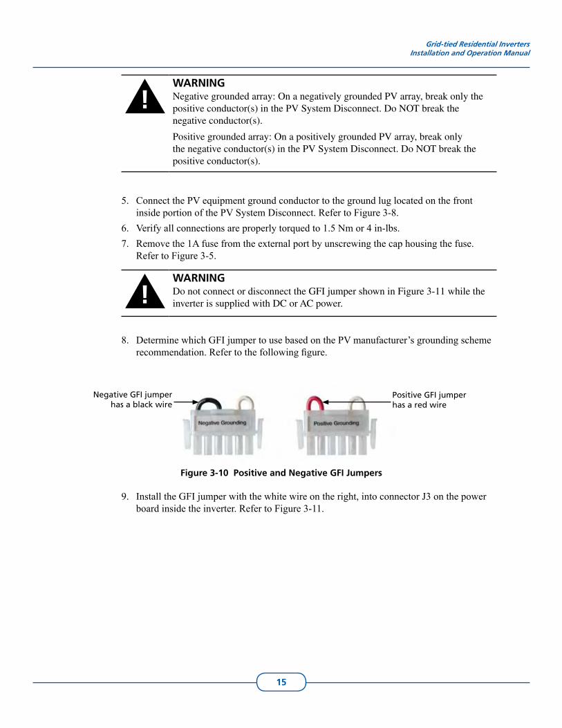
Determine which GFI jumper to use based on the PV manufacturer’s grounding scheme 8. recommendation. Refer to the following figure.
Negative GFI jumper has a black wire
Positive GFI jumper has a red wire
Figure 3-10 Positive and Negative GFI Jumpers
Install the GFI jumper with the white wire on the right, into connector J3 on the power 9. board inside the inverter. Refer to Figure 3-11.
16
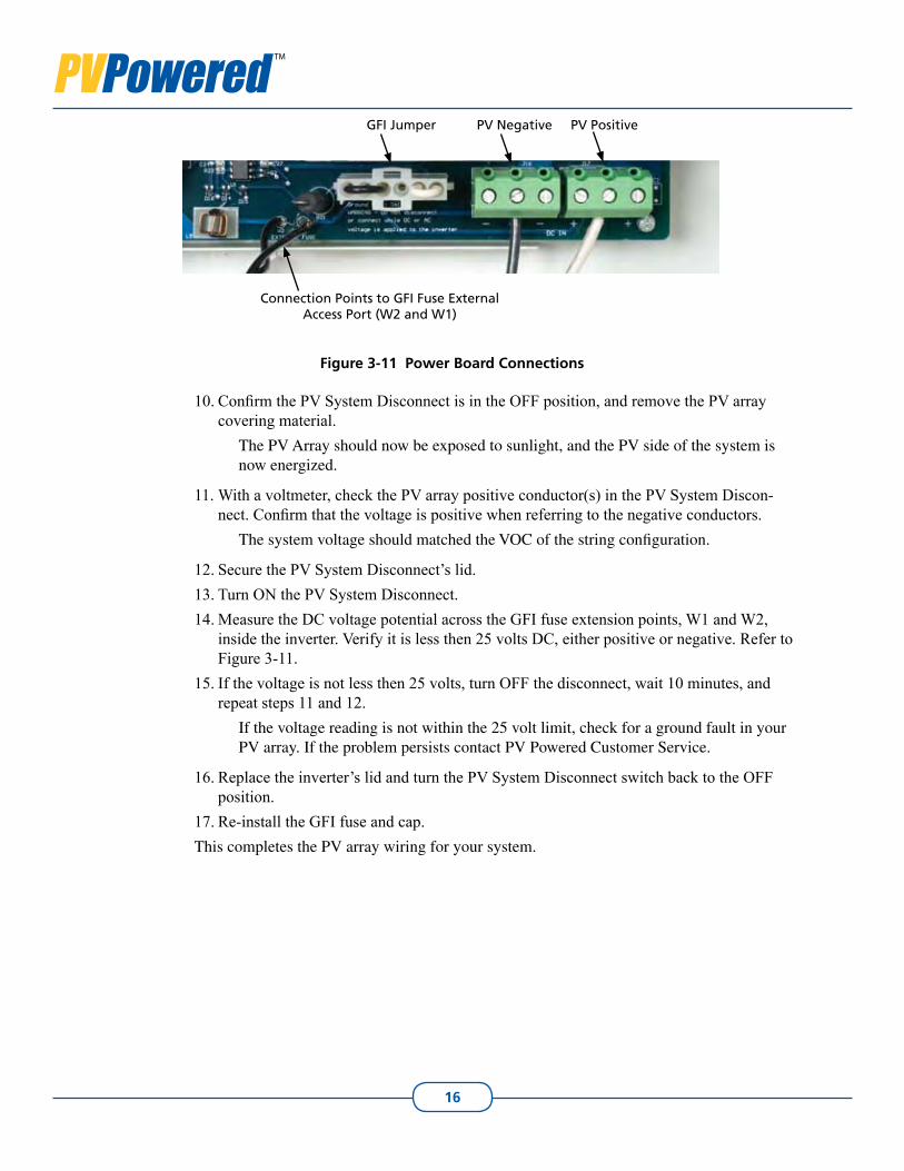
GFI Jumper PV Negative PV Positive
Connection Points to GFI Fuse External Access Port (W2 and W1)
Figure 3-11 Power Board Connections
Confirm the PV System Disconnect is in the OFF position, and remove the PV array 10. covering material.
The PV Array should now be exposed to sunlight, and the PV side of the system is now energized.
With a voltmeter, check the PV array positive conductor(s) in the PV System Discon-11. nect. Confirm that the voltage is positive when referring to the negative conductors.
The system voltage should matched the VOC of the string configuration.
Secure the PV System Disconnect’s lid.12. Turn ON the PV System Disconnect.13. Measure the DC voltage potential across the GFI fuse extension points, W1 and W2, 14. inside the inverter. Verify it is less then 25 volts DC, either positive or negative. Refer to Figure 3-11.If the voltage is not less then 25 volts, turn OFF the disconnect, wait 10 minutes, and 15. repeat steps 11 and 12.
If the voltage reading is not within the 25 volt limit, check for a ground fault in your PV array. If the problem persists contact PV Powered Customer Service.
Replace the inverter’s lid and turn the PV System Disconnect switch back to the OFF 16. position.Re-install the GFI fuse and cap.17.
This completes the PV array wiring for your system.
17
4. Operations
!WARNINGBefore turning on the inverter, ensure that the front cover is closed properly.
!WARNINGThe heat sink can reach temperatures in excess of 158ºF (70ºC). Do not touch the heat sink when in use, and do not place anything on top of the heat sink.
Start up Procedures4.1
To start up the inverter, complete the following steps in the order indicated.
NOTE: All steps are assumed completed in previous sections; including but not limited to:
VOC calculation•Checking the system for ground faults•
1. Turn the AC breaker ON.Verify that the red LED light is illuminated. The LEDs are located in the upper left hand corner of the inverter’s display.
If the red LED is not illuminated or is blinking, refer to the • Troubleshooting sec-tion.
Turn the PV System Disconnect ON.2. The green LED should illuminate. If not, refer to the Troubleshooting section.
If no green LED illuminates, verify DC voltage is present in the PV System • Disconnect. The DC voltage present should be at least 15 volts greater than the minimum operating voltage stated in Appendix A.
After five minutes the inverter starts to produce power if all necessary operating conditions are met.
NOTE: PV Powered recommends that a lock be attached to prevent unauthorized access or damage to the inverter.
Inverter Front Panel Status Indicators4.2
The inverter continuously monitors:
The AC grid connection to ensure the AC voltage and frequency levels are within safe 1. operating limits per UL1741. The DC voltage and current from the PV array to ensure safe operating conditions per 2. UL 1741.
OPER
ATIO
NS
18
The inverter’s internal operational parameters to ensure safe operating conditions exist 3. within the operating environment.
The inverter has two LED indicator lights visible through the upper left corner of the lid. These lights indicate the inverter’s status.
Green LED is illuminated when:
All three monitored operating conditions are met.• Inverter’s operating environment is safe to export power to the AC grid.•
Red LED flashes when:
Any one of the monitored operating conditions are not met.• When a fault condition exists.• The operating environment moves outside the safe operating limits governed by UL • 1741, IEEE 1547, and IEEE 519.
Red LED is illuminated when:
The PV array voltage is not within required operating limits, such as:• At sunset, when the inverter turns off for the night. • When clouds reduce the amount of available sunlight or when portions of the PV • array are covered with debris. Any time the DC output from the PV array drops below the inverter’s minimum • DC operating voltage, the inverter turns off.
When the array is once again exposed to enough sunlight, the green LED illuminates, the inverter’s auto-start feature begins, and after five minutes the inverter begins to export power.
If the red LED continues to illuminate when there is sufficient sunlight for operation, verify that no wiring connections are loose. If the wiring is secure, see the Troubleshooting section for additional information.
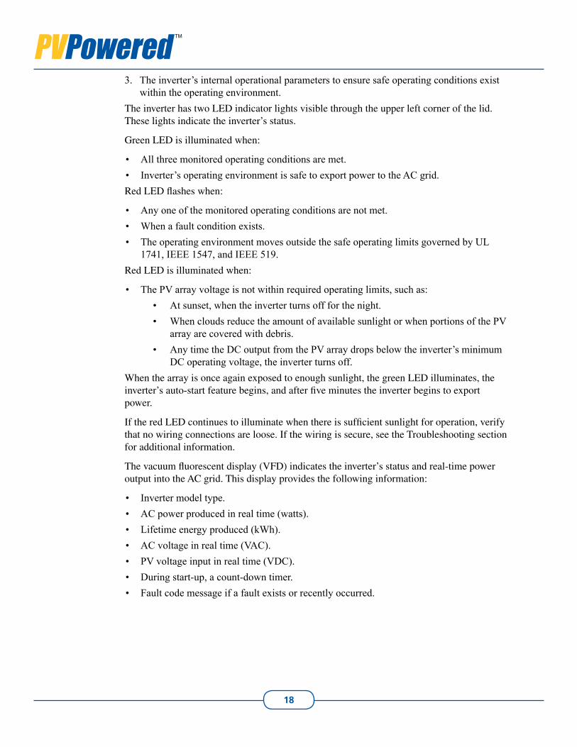
The vacuum fluorescent display (VFD) indicates the inverter’s status and real-time power output into the AC grid. This display provides the following information:
Inverter model type.• AC power produced in real time (watts).• Lifetime energy produced (kWh).• AC voltage in real time (VAC).• PV voltage input in real time (VDC).• During start-up, a count-down timer.• Fault code message if a fault exists or recently occurred.•
19
Grid-tied Residential InvertersInstallation and Operation Manual
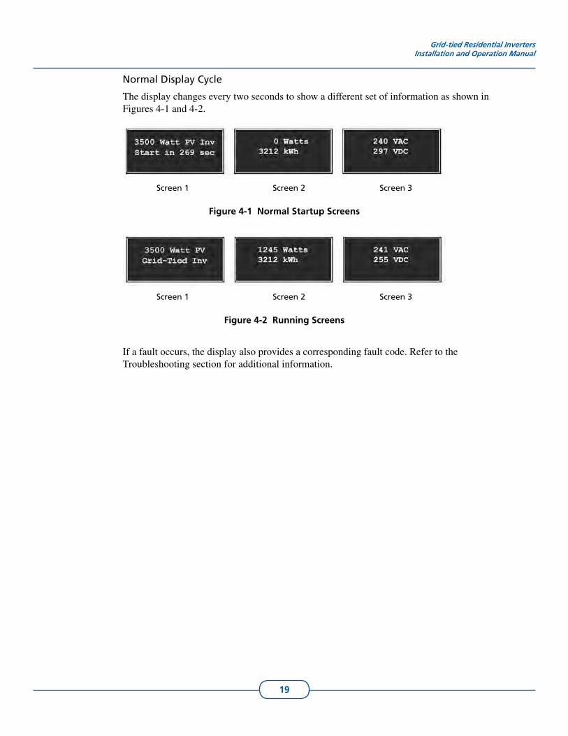
Normal Display Cycle
The display changes every two seconds to show a different set of information as shown in Figures 4-1 and 4-2.
Screen 1 Screen 2 Screen 3
Figure 4-1 Normal Startup Screens
Screen 1 Screen 2 Screen 3
Figure 4-2 Running Screens
If a fault occurs, the display also provides a corresponding fault code. Refer to the Troubleshooting section for additional information.
20
5. Troubleshooting
The inverter provides two indicator lights in the form of Light Emitting Diodes, or LEDs. The LEDs are the primary indicators of the system status: O.K., Sleep or Faulted. The LEDs are located above the inverter display in the upper left hand corner on the front lid.
LED Status5.1
Red LED
The light on the left is a red LED and is the primary indicator of system stand-by or 1. fault condition. A solid red LED and a blank screen indicates the system is in normal sleep or stand-by 2. mode. This mode occurs if there is not enough sunlight present to generate DC voltage at night and the AC properties are within the provided specifications.The red LED blinks if the inverter has had a fault condition, and the vacuum fluorescent 3. display (VFD) displays a fault code. If the red LED is blinking, carefully record the numerical error code and text describing the error. Possible faults are listed in Table 5-1.
Green LED
The light on the right is a green LED and is the primary indicator the system is generat-1. ing power.The green LED illuminates any time the DC voltage is above the inverter’s DC start 2. voltage and all operational parameters are met. When the green light illuminates, the inverter tries to convert power from the PV array.
Red and Green LED Lights On
If both LED lights are solid at the same time, contact PV Powered Technical Support for assistance.
Ground Fault Error
!WARNINGReplace the GFI fuse with the same type and rating of fuse. The inverter uses Littelfuse KLKD1 1A/600VDC.
The inverter’s GFDI circuit reports a ground fault error if the 1 amp fuse is blown and 1. the voltage potential between ground and the grounded terminal of the PV array is greater than +25 VDC, or less than -25 VDC. This voltage potential can only occur if the ground fault fuse in the inverter has opened.A ground fault occurs when unintended current has a path to ground. The most common 2. source of a PV system ground faults are crossed wires, a nicked PV module conductor touching a grounded surface, or cables inside a conduit have metal exposed through the insulation. A less likely cause is limited to multiple inverter installations, when the positive and 3. negative array strings are crossed. Crossed wires occur when a positive or negative
TRO
UB
LESH
OO
TING
21
conductor from array 1 is connected with wires in array 2. An example is if inverter A has the positive conductor from array 1 and the negative conductor from array 2 con-nected.If the fuse is blown or open, then a ground fault condition exists. 4.
Check the DC voltage between the grounded terminal of the array and earth ground.• The voltage should be less than 25 VDC with the GFI fuse removed. If the voltage is •greater than this, check the array wiring as there may be a ground fault. For the best results, perform this test with the PV System Disconnect on and off. If you are not comfortable conducting this test, DO NOT ATTEMPT IT. (See PV System Discon-nect, Installation and Operations Manual for AC and DC disconnect information).
If a ground fault condition is not present because it is now repaired or intermittent, • replace the fuse with a similar fuse rated at 600VDC and 1A.
Make sure the grounded leg of the PV array is not broken in the PV System Disconnect.5.
Note: The GFI is a latching circuit which prevents the inverter from operating until the fault is repaired and the inverter is reset. The inverter will not operate, even if the fault is repaired, unless it is manually reset by turning the AC source circuit off and then on.
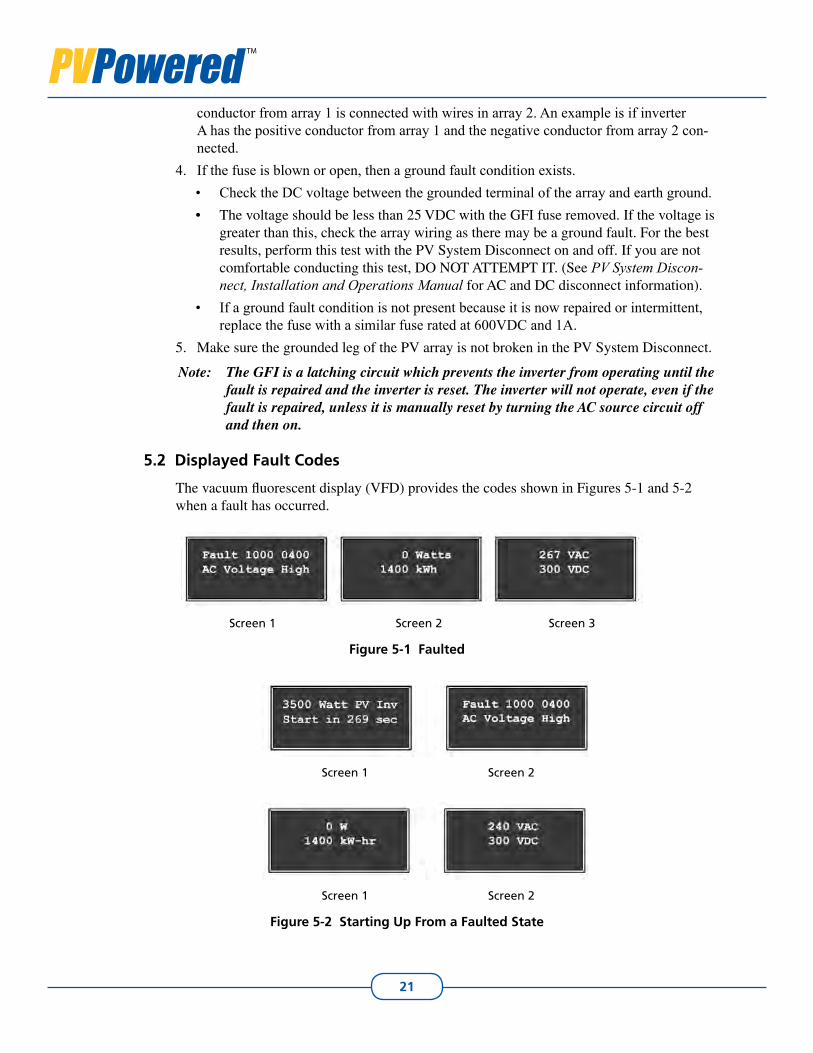
Displayed Fault Codes5.2
The vacuum fluorescent display (VFD) provides the codes shown in Figures 5-1 and 5-2 when a fault has occurred.
Screen 1 Screen 2 Screen 3
Figure 5-1 Faulted
Screen 1 Screen 2
Screen 1 Screen 2
Figure 5-2 Starting Up From a Faulted State
22
Grid-tied Residential InvertersInstallation and Operation Manual
NOTE: In this case the fault refers to the last fault detected.
If the inverter is in a faulted state, the red LED blinks and the VFD scrolls through the screens shown in the faulted example above. The text of the fault describes the specific fault condition that the inverter experienced.
If the inverter is no longer experiencing the condition that caused the fault (e.g. the AC voltage climbs above 264V then drops below 264V), the red LED stops blinking and the inverter starts the five minute count-down timer. During these five minutes, the display also shows the last fault.
Multiple Faults
If the inverter detects multiple faults at one time, the inverter displays the text of the first fault detected.
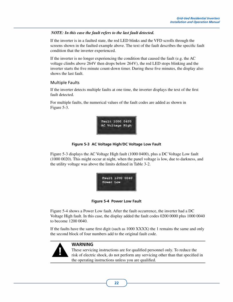
For multiple faults, the numerical values of the fault codes are added as shown in Figure 5-3.
Figure 5-3 AC Voltage High/DC Voltage Low Fault
Figure 5-3 displays the AC Voltage High fault (1000 0400), plus a DC Voltage Low fault (1000 0020). This might occur at night, when the panel voltage is low, due to darkness, and the utility voltage was above the limits defined in Table 3-2.
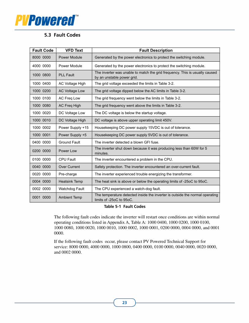
Figure 5-4 Power Low Fault
Figure 5-4 shows a Power Low fault. After the fault occurrence, the inverter had a DC Voltage High fault. In this case, the display added the fault codes 0200 0000 plus 1000 0040 to become 1200 0040.
If the faults have the same first digit (such as 1000 XXXX) the 1 remains the same and only the second block of four numbers add to the original fault code.
!WARNINGThese servicing instructions are for qualified personnel only. To reduce the risk of electric shock, do not perform any servicing other than that specified in the operating instructions unless you are qualified.
23
Fault Codes5.3
Fault Code VFD Text Fault Description8000 0000 Power Module Generated by the power electronics to protect the switching module.
4000 0000 Power Module Generated by the power electronics to protect the switching module.
1000 0800 PLL FaultThe inverter was unable to match the grid frequency. This is usually caused by an unstable power grid.
1000 0400 AC Voltage High The grid voltage exceeded the limits in Table 3-2.
1000 0200 AC Voltage Low The grid voltage dipped below the AC limits in Table 3-2.
1000 0100 AC Freq Low The grid frequency went below the limits in Table 3-2.
1000 0080 AC Freq High The grid frequency went above the limits in Table 3-2.
1000 0020 DC Voltage Low The DC voltage is below the startup voltage.
1000 0010 DC Voltage High DC voltage is above upper operating limit 450V.
1000 0002 Power Supply +15 Housekeeping DC power supply 15VDC is out of tolerance.
1000 0001 Power Supply +5 Housekeeping DC power supply 5VDC is out of tolerance.
0400 0000 Ground Fault The inverter detected a blown GFI fuse.
0200 0000 Power LowThe inverter shut down because it was producing less than 60W for 5 minutes.
0100 0000 CPU Fault The inverter encountered a problem in the CPU.
0040 0000 Over Current Safety protection. The inverter encountered an over-current fault.
0020 0000 Pre-charge The inverter experienced trouble energizing the transformer.
0004 0000 Heatsink Temp The heat sink is above or below the operating limits of -25oC to 95oC.
0002 0000 Watchdog Fault The CPU experienced a watch-dog fault.
0001 0000 Ambient TempThe temperature detected inside the inverter is outside the normal operating limits of -25oC to 95oC.
Table 5-1 Fault Codes
The following fault codes indicate the inverter will restart once conditions are within normal operating conditions listed in Appendix A, Table A: 1000 0400, 1000 0200, 1000 0100, 1000 0080, 1000 0020, 1000 0010, 1000 0002, 1000 0001, 0200 0000, 0004 0000, and 0001 0000.
If the following fault codes occur, please contact PV Powered Technical Support for service: 8000 0000, 4000 0000, 1000 0800, 0400 0000, 0100 0000, 0040 0000, 0020 0000, and 0002 0000.
24
Appendix A - Specifications
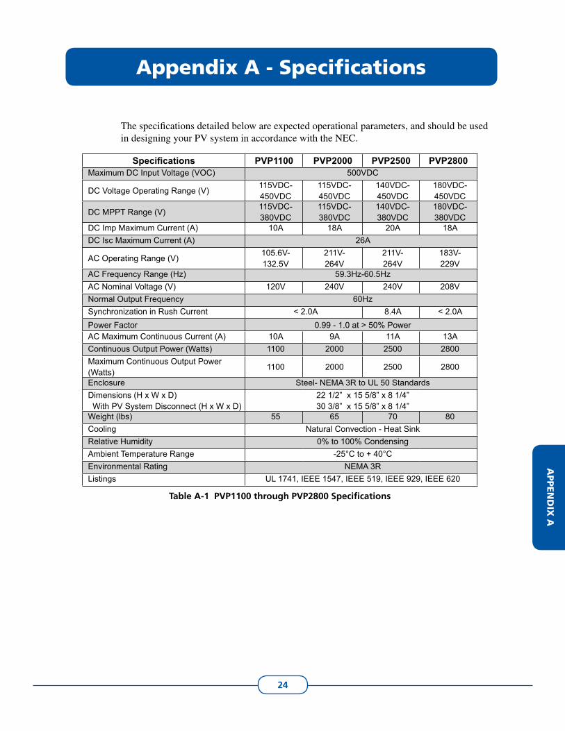
The specifications detailed below are expected operational parameters, and should be used in designing your PV system in accordance with the NEC.
Specifications PVP1100 PVP2000 PVP2500 PVP2800 Maximum DC Input Voltage (VOC) 500VDC
DC Voltage Operating Range (V)115VDC-450VDC
115VDC-450VDC
140VDC-450VDC
180VDC- 450VDC
DC MPPT Range (V)115VDC-380VDC
115VDC-380VDC
140VDC-380VDC
180VDC- 380VDC
DC Imp Maximum Current (A) 10A 18A 20A 18ADC Isc Maximum Current (A) 26A
AC Operating Range (V)105.6V-132.5V
211V-264V
211V-264V
183V-229V
AC Frequency Range (Hz) 59.3Hz-60.5HzAC Nominal Voltage (V) 120V 240V 240V 208VNormal Output Frequency 60HzSynchronization in Rush Current < 2.0A 8.4A < 2.0APower Factor 0.99 - 1.0 at > 50% PowerAC Maximum Continuous Current (A) 10A 9A 11A 13AContinuous Output Power (Watts) 1100 2000 2500 2800Maximum Continuous Output Power (Watts)
1100 2000 2500 2800
Enclosure Steel- NEMA 3R to UL 50 StandardsDimensions (H x W x D) With PV System Disconnect (H x W x D)
22 1/2” x 15 5/8” x 8 1/4”30 3/8” x 15 5/8” x 8 1/4”
Weight (lbs) 55 65 70 80Cooling Natural Convection - Heat SinkRelative Humidity 0% to 100% CondensingAmbient Temperature Range -25°C to + 40°CEnvironmental Rating NEMA 3RListings UL 1741, IEEE 1547, IEEE 519, IEEE 929, IEEE 620
Table A-1 PVP1100 through PVP2800 Specifications
APPEN
DIX
A
25
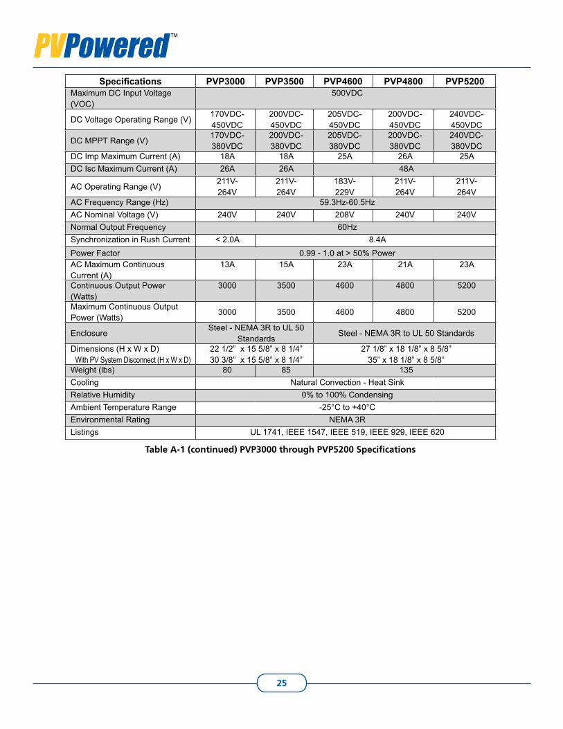
Specifications PVP3000 PVP3500 PVP4600 PVP4800 PVP5200 Maximum DC Input Voltage (VOC)
500VDC
DC Voltage Operating Range (V)170VDC-450VDC
200VDC-450VDC
205VDC-450VDC
200VDC-450VDC
240VDC-450VDC
DC MPPT Range (V)170VDC-380VDC
200VDC-380VDC
205VDC-380VDC
200VDC-380VDC
240VDC-380VDC
DC Imp Maximum Current (A) 18A 18A 25A 26A 25ADC Isc Maximum Current (A) 26A 26A 48A
AC Operating Range (V)211V-264V
211V-264V
183V-229V
211V-264V
211V-264V
AC Frequency Range (Hz) 59.3Hz-60.5HzAC Nominal Voltage (V) 240V 240V 208V 240V 240VNormal Output Frequency 60HzSynchronization in Rush Current < 2.0A 8.4APower Factor 0.99 - 1.0 at > 50% PowerAC Maximum Continuous Current (A)
13A 15A 23A 21A 23A
Continuous Output Power (Watts)
3000 3500 4600 4800 5200
Maximum Continuous Output Power (Watts)
3000 3500 4600 4800 5200
EnclosureSteel - NEMA 3R to UL 50
StandardsSteel - NEMA 3R to UL 50 Standards
Dimensions (H x W x D) With PV System Disconnect (H x W x D)
22 1/2” x 15 5/8” x 8 1/4”30 3/8” x 15 5/8” x 8 1/4”
27 1/8” x 18 1/8” x 8 5/8”35” x 18 1/8” x 8 5/8”
Weight (lbs) 80 85 135Cooling Natural Convection - Heat SinkRelative Humidity 0% to 100% CondensingAmbient Temperature Range -25°C to +40°CEnvironmental Rating NEMA 3RListings UL 1741, IEEE 1547, IEEE 519, IEEE 929, IEEE 620
Table A-1 (continued) PVP3000 through PVP5200 Specifications
26
Grid-tied Residential InvertersInstallation and Operation Manual
Abnormal Specifications
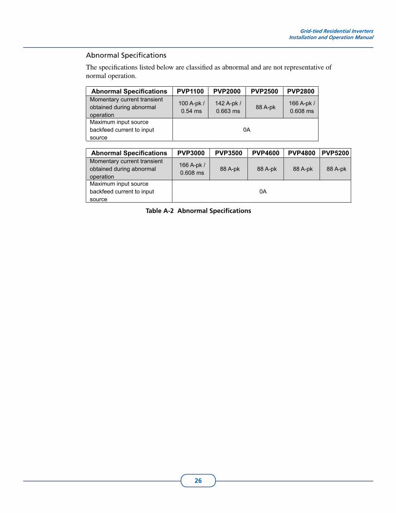
The specifications listed below are classified as abnormal and are not representative of normal operation.
Abnormal Specifications PVP1100 PVP2000 PVP2500 PVP2800 Momentary current transient obtained during abnormal operation
100 A-pk / 0.54 ms
142 A-pk / 0.663 ms
88 A-pk166 A-pk / 0.608 ms
Maximum input source backfeed current to input source
0A
Abnormal Specifications PVP3000 PVP3500 PVP4600 PVP4800 PVP5200 Momentary current transient obtained during abnormal operation
166 A-pk / 0.608 ms
88 A-pk 88 A-pk 88 A-pk 88 A-pk
Maximum input source backfeed current to input source
0A
Table A-2 Abnormal Specifications
27
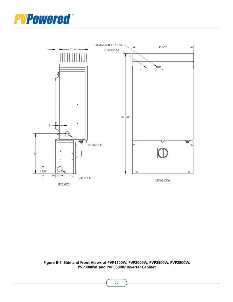
Figure B-1 Side and Front Views of PVP1100W, PVP2000W, PVP2500W, PVP2800W, PVP3000W, and PVP3500W Inverter Cabinet
15 5/8"
30 3/8"
LED STATUS INDICATORS
VFD DISPLAY
3"
1" 7 1/4"
10"
1 1/8"
1"3/4", 1" K.O.
1/2", 3/4" K.O.
LEFT VIEWFRONT VIEW
28
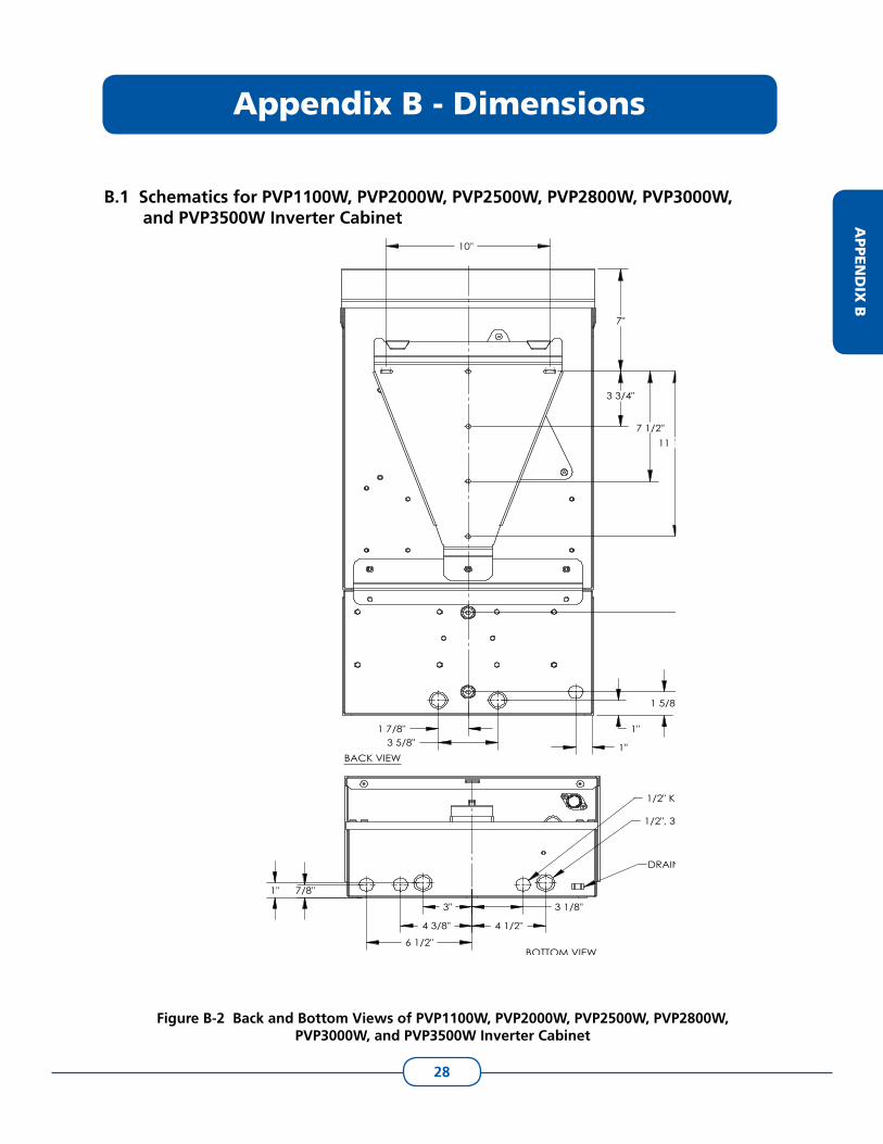
Schematics for B.1 PVP1100W, PVP2000W, PVP2500W, PVP2800W, PVP3000W, and PVP3500W Inverter Cabinet
7"
3 3/4"
7 1/2"11 1/4"
3 5/8"
16 1/2"
21 7/8"
1"
1 5/8"
1"
1 7/8"
10"
BACK VIEW
7/8"1"
3"
4 3/8"
6 1/2"
3 1/8"
4 1/2"
1/2", 3/4" K.O.
1/2" K.O.
DRAINAGE PORT
BOTTOM VIEW
Figure B-2 Back and Bottom Views of PVP1100W, PVP2000W, PVP2500W, PVP2800W, PVP3000W, and PVP3500W Inverter Cabinet
Appendix B - Dimensions
APPEN
DIX
B
29
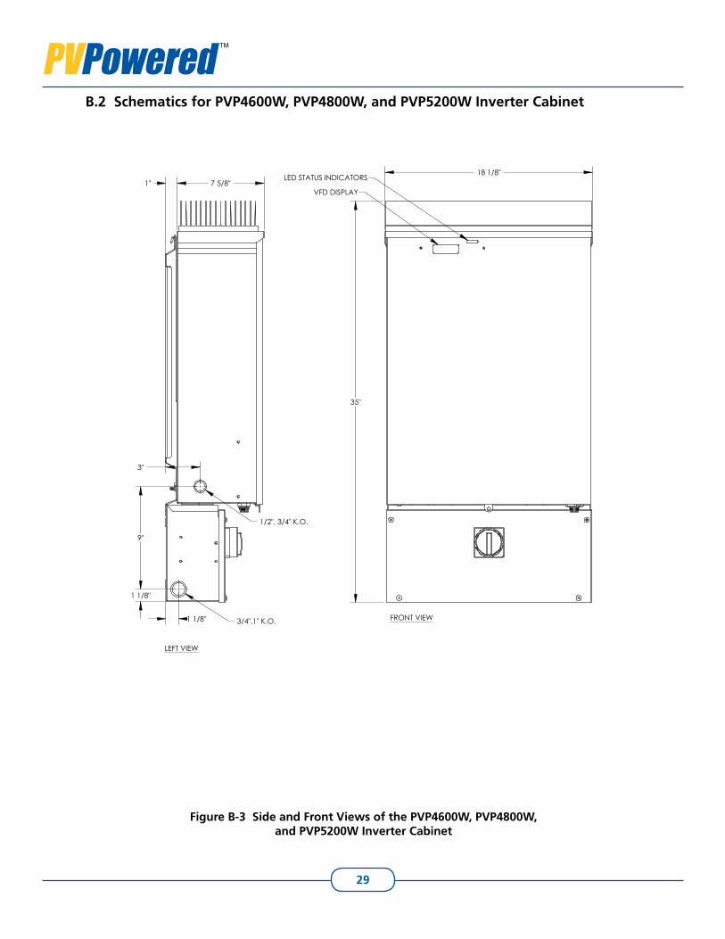
Schematics for PVP4600W, PVP4800W, and PVP5200W Inverter CabinetB.2
Figure B-3 Side and Front Views of the PVP4600W, PVP4800W, and PVP5200W Inverter Cabinet
18 1/8"
35"
LED STATUS INDICATORS
VFD DISPLAY7 5/8"1"
3"
1 1/8"
1 1/8"
9"
3/4",1" K.O.
1/2", 3/4" K.O.
LEFT VIEW
FRONT VIEW
30
Grid-tied Residential InvertersInstallation and Operation Manual
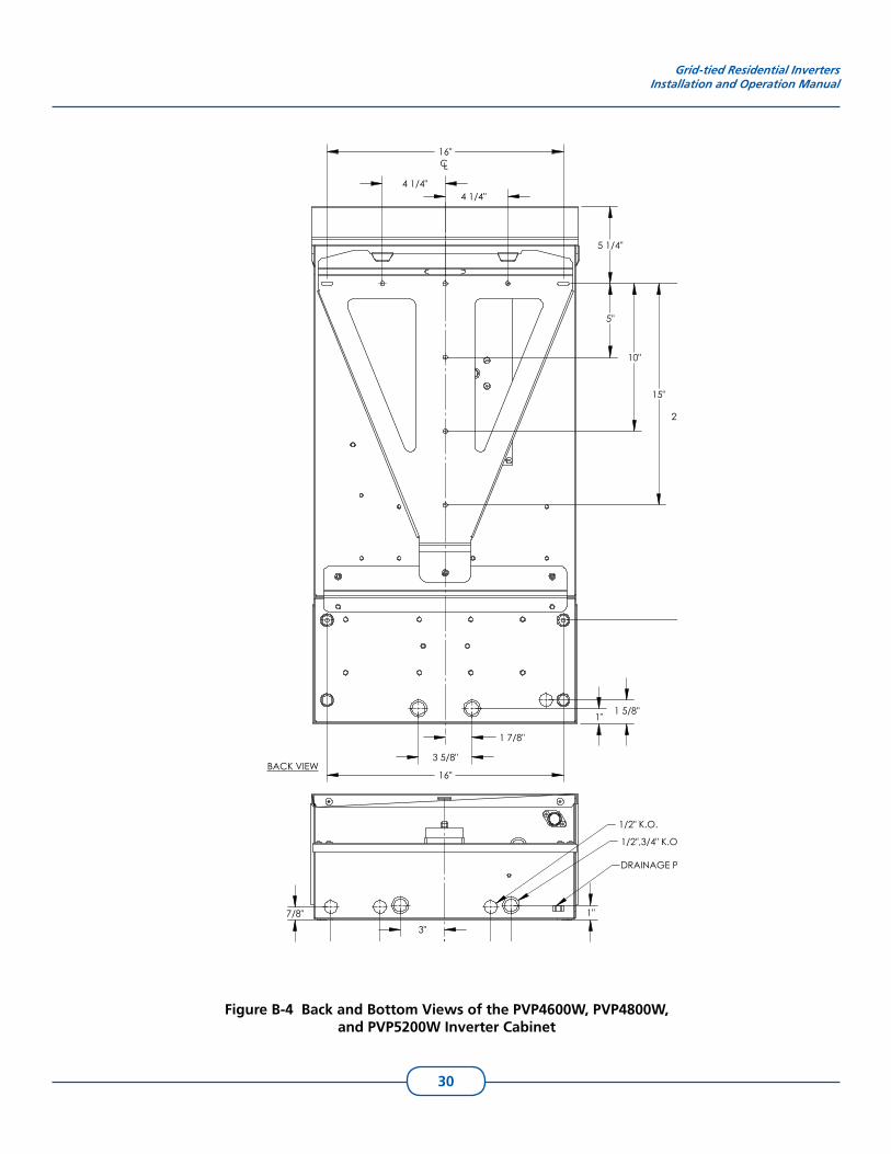
Figure B-4 Back and Bottom Views of the PVP4600W, PVP4800W, and PVP5200W Inverter Cabinet
4 1/4"4 1/4"
5 1/4"
5"
10"
15"
22 3/4"
16"
1 5/8"1"
1 7/8"
3 5/8"
16"CL
BACK VIEW
3"
4 3/8"
7 3/4"
3 1/8"
4 1/2"
7/8" 1"
1/2" K.O.
1/2",3/4" K.O.
DRAINAGE PORT
BOTTOM VIEW

31
Limited Warranty
PV Powered, Inc. provides a limited warranty for your residential or commercial inverter and optional data monitoring module for defects caused by material or manufacturing flaws. The inverter and the data monitoring module must be installed and maintained by a qualified installer in order for the warranty to be valid.
Terms of Coverage
The warranty period for the inverter is ten years, and the warranty on the data monitoring module is one year, each beginning on the date of purchase by the original end user.
Coverage
PV Powered will, at its option, repair or replace the defective component(s) free of charge, provided that you notify PV Powered of the defect during the warranty period, have a dated proof of purchase, and PV Powered determines that the defect is covered by the limited warranty set forth above. PV Powered reserves the right to inspect the defective component(s) and determine if the defect is due to material or manufacturing flaws. PV Powered also reserves the right to charge a fee for service time expended if the defect is not due to material or manufacturing flaw or is not for some other reason subject to this limited warranty.
PV Powered will, at its option, use new and/or reconditioned parts in performing warranty repair and in building replacement products. PV Powered reserves the right to use parts or products of original or improved design in the repair or replacement. If PV Powered repairs or replaces a product, its warranty continues for the remaining portion of the original warranty period or 90 days from the date of the return shipment to the customer, whichever period expires later. All replaced products and all parts removed from repaired products become the property of PV Powered.
For defects covered by this limited warranty, PV Powered will provide, at no additional cost to the customer, both parts and labor necessary to repair the product, and return shipment to the customer via a PV Powered selected, non-expedited, surface freight carrier within the United States and Canada.
What is Not Covered
PV Powered does not warrant its products from any and all defects or damage caused by:
Normal wear and tear.• Shipping or transportation damages.• Improper installation.• Improper maintenance.• Excessive voltage or current conditions from the electrical grid or PV panels. • Exposure to unsuitable environmental conditions (including but not limited to damage • due to lightning strikes, storm, fire, flood, etc.).Unauthorized or abnormal use, repair, modification, or operation.• Negligence or accidents.•
WA
RR
AN
TY

32
Material or workmanship not provided by PV Powered or its authorized service centers.• This warranty also does not cover costs related to the removal, installation, or troubleshooting of your electrical systems.
Disclaimer and Limitation of Liability
EXCEPT FOR THIS EXPRESS LIMITED WARRANTY, PV POWERED EXPRESSLY EXCLUDES ALL WARRANTIES WITH RESPECT TO THE INVERTER AND DATA MONITORING MODULE, EXPRESS AND IMPLIED, INCLUDING BUT NOT LIMITED TO THE WARRANTY OF MERCHANTABILITY, THE WARRANTY OF FITNESS FOR A PARTICULAR PURPOSE, AND ANY WARRANTIES THAT MAY HAVE ARISEN FROM COURSE OF DEALING OR USAGE OF TRADE.
TO THE MAXIMUM EXTENT PERMITTED BY LAW, PV POWERED’S AGGREGATE MONETARY LIABILITY TO THE CUSTOMER FOR ANY REASON AND FOR ANY AND ALL CAUSES OF ACTION, WHETHER IN CONTRACT, TORT OR OTHERWISE, WILL NOT EXCEED THE AMOUNT PAID TO PV POWERED FOR THE INVERTER OR DATA MONITORING DEVICE. PV POWERED WILL NOT BE LIABLE TO YOU UNDER ANY CAUSE OF ACTION, WHETHER IN CONTRACT, TORT OR OTHERWISE, FOR ANY INDIRECT, SPECIAL, INCIDENTAL, CONSEQUENTIAL, OR PUNITIVE DAMAGES, EVEN IF PV POWERED HAS BEEN ADVISED OF THE POSSIBILITY OF SUCH DAMAGES. THE ORIGINAL PRICE FOR THE INVERTER AND DATA MONITORING MODULE AND PV POWERED’S OBLIGATIONS UNDER THIS EXPRESS LIMITED WARRANTY ARE CONSIDERATION FOR LIMITING PV POWERED’S LIABILITY.
IF THIS PRODUCT IS A CONSUMER PRODUCT, FEDERAL LAW DOES NOT ALLOW AN EXCLUSION OF IMPLIED WARRANTIES. TO THE EXTENT YOU ARE ENTITLED TO IMPLIED WARRANTIES UNDER FEDERAL LAW, TO THE EXTENT PERMITTED BY APPLICABLE LAW THEY ARE LIMITED TO THE DURATION OF THIS LIMITED WARRANTY. SOME STATES AND PROVINCES DO NOT ALLOW LIMITATIONS OR EXCLUSIONS ON IMPLIED WARRANTIES OR ON THE DURATION OF AN IMPLIED WARRANTY OR ON THE LIMITATION OR EXCLUSION OF INCIDENTAL OR CONSEQUENTIAL DAMAGES, SO THE ABOVE LIMITATION(S) OR EXCLUSION(S) MAY NOT APPLY TO YOU. THIS LIMITED WARRANTY GIVES YOU SPECIFIC LEGAL RIGHTS. YOU MAY HAVE OTHER RIGHTS WHICH MAY VARY FROM STATE TO STATE OR PROVINCE TO PROVINCE.
Arbitration
IN THE EVENT OF A DISPUTE BETWEEN PV POWERED AND ANY PURCHASER COVERED UNDER THIS WARRANTY, TO THE MAXIMUM EXTENT ALLOWED BY LAW, THE PURCHASER AGREES TO RESOLVE ANY AND ALL SUCH DISPUTES USING BINDING ARBITRATION IN ACCORDANCE WITH THE RULES AND PROCEDURES OF THE ARBITRATION SERVICE OF PORTLAND, INC., AND JUDGMENT UPON AWARD RENDERED PURSUANT TO SUCH ARBITRATION SHALL BE BINDING ON THE PARTIES. THE LOCATION FOR ANY ARBITRATION HEARINGS SHALL BE BEND, OREGON. THE PRICE FOR THE INVERTER OR PVM1010 DEVICE AND PV POWERED’S OBLIGATIONS UNDER THIS EXPRESS LIMITED WARRANTY ARE CONSIDERATION FOR THIS BINDING ARBITRATION PROVISION.

33
Return Procedure
Before returning the product directly to PV Powered, you must first obtain a Return Materials Authorization Number (RMA) from PV Powered. You must also pre-pay for shipping. When you contact a PV Powered representative, please have the following information ready:
The serial number of the product1. The reason for the return2. A copy of your dated proof of purchase3.
When you return the product to PV Powered, PV Powered advises that you use the original packaging or its equivalent, and that you fully insure the shipped product. PV Powered is not responsible for damage to the product due to improper packaging.
On the packaging, please include the following:
Clearly mark the Return Materials Authorization Number (supplied by PV 1. Powered) on the outside of the box.A return address where the product can be shipped.2. A telephone number where you can be reached during business hours.3. A brief description of the problem.4.
Ship the product prepaid to the address provided by your PV Powered representative.
Information about Your System
Note the following information for your records, and retain your dated proof of purchase:
Serial Number __________________________________________________________
Purchased From _________________________________________________________
Date of Purchase ________________________________________________________
RETU
RN
PR
OC
ED
UR
E
34
Index
Aabbreviations iiiAC
grounding 10wiring 12
acronyms iiianchoring 5
Bbracket 3, 5, 6, 7
Ccalculating VOC 14caution
information about iichecking voltage 16circuit boards 12circuit breaker
requirements 8circuits 10clearances 3conductor sizing 9, 12conduit hubs 9connecting
DC 14inverter to grid 12
connectionstorque 13
contact information icontrol board 12covering
PV panels 14
Ddanger
information about iiData Monitoring Module 10DC
grounding 10wiring 14
diagramssmall inverter/disconnect 28
dimensions 28disconnect 15
grounding 13grounding lug 15locking tab 1wire raceway 13
display 3, 17drainage port 9
EEGC 9energizing system 16
Ffault codes 18, 19, 21, 23
multiple 22faults
nuisance 9, 12FCC compliance 2fuse 11, 12
removing 15
GGEC 10GFI 11
access to 9activating circuit 11fuse type 11jumper 11
ground fault 11, 20display 12
groundingsingle-point 10, 11
grounding lug 15
Hheatsink 3, 17
Iinverter
anchoring 5brackets 3circuit boards 12circuit breaker requirements 8components 4connecting 12connecting to PV array 14control board 12dimensions 28display 21drainage port 9enclosure 3energizing 16fault codes 18, 21, 23GFI access 9locating 3mounting 3, 5power distribution board 12removing cover 6schematics 27specifications 24, 25starting 16, 17status information 17troubleshooting 20ventilation 3voltage frequency limits 8
IND
EX
35
Jjumper 11
LLEDs 17, 20locating inverter 3locking tab 1
Mmonitoring LEDs 17, 20mounting 5, 6
inverter 3screws 3
NNEMA 3
Pport
drainage 9GFI access 9
power distribution board 12PV Powered
how to contact i
Ssafety 1
conventions iischematics 27screens 19, 21specifications 25
abnormal 26diagrams 28–30
starting inverter 17stud, in wall 5system disconnect 12
Ttemperature 14torque 15
of connections 13
Vventilation
for inverter 3VOC calculation 14voltage
checking 16voltage drop 9voltage frequency limits 8voltage maximums 14
Wwarning
information about iiwarranty 31wiring
raceway 13

PO Box 7348 • Bend, OR 97708 • P: 541-312-3832 • www.pvpowered.com