cps sca series grid-tied pv inverter - chint power · pdf filecps sca series grid-tied pv...
TRANSCRIPT

CPS SCA Series Grid-tied PV InverterCPS SCA3/4/5/KTL-O/US
Installation and Operation Manual
Ver 1.0

CHINT POWER SYSTEMS AMERICA CO., LTD.
Web: www.chintpower.com/naEmail: [email protected] Hotline: 855-584-7168
SHANGHAI CHINT POWER SYSTEMS CO., LTD. All rights reserved.Specifications and designs included in this manual are subject to change without notice.CHINT POWER 2013/10-MKT PN: 9.0020.0097A0
Address: 700 International Parkway Suite 102 Richardson TX 75081
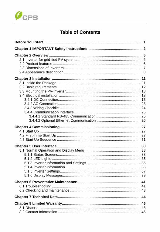
Table of Contents
Before You Start… ...............................................................................................1
Chapter 1 IMPORTANT Safety Instructions .......................................................2
Chapter 2 Overview .............................................................................................5
2.1 Inverter for grid-tied PV systems.................................................................5 2.2 Product features .........................................................................................6 2.3 Dimensions of Inverters ..............................................................................7 2.4 Appearance description ..............................................................................8
Chapter 3 Installation ........................................................................................ 11
3.1 Inside the Package ................................................................................... 11 3.2 Basic requirements ................................................................................... 12 3.3 Mounting the PV-Inverter .......................................................................... 13 3.4 Electrical installation ................................................................................. 18
3.4.1 DC Connection.................................................................................. 18 3.4.2 AC Connection .................................................................................. 23 3.4.3 Wiring Checklist ................................................................................ 24 3.4.4 Communication Interface .................................................................. 25
3.4.4.1 Standard RS-485 Communication ............................................. 25 3.4.4.2 Optional Ethernet Communication ............................................ 26
Chapter 4 Commissioning ................................................................................ 27
4.1 Start Up .................................................................................................... 27 4.2 First-Time Start Up ................................................................................... 27 4.3 Start Up Sequence ................................................................................... 31
Chapter 5 User Interface ................................................................................... 33
5.1 Normal Operation and Display Menu ........................................................ 33 5.1.1 Status Screens.................................................................................. 33 5.1.2 LED Lights ........................................................................................ 35 5.1.3 Inverter Information and Settings ...................................................... 35 5.1.4 Inverter Information ........................................................................... 36 5.1.5 Inverter Settings ................................................................................ 37 5.1.6 Display Messages ............................................................................. 39
Chapter 6 Preventative Maintenance ............................................................... 41
6.1 Troubleshooting ........................................................................................ 41 6.2 Checking and maintenance ...................................................................... 43
Chapter 7 Technical Data .................................................................................. 44
Chapter 8 Limited Warranty .............................................................................. 46
8.1 Disposal .................................................................................................... 46 8.2 Contact Information .................................................................................. 46
1
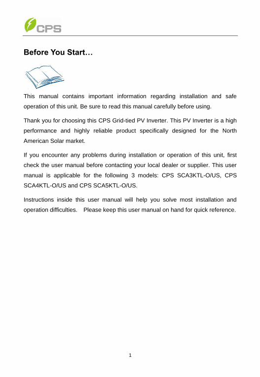
Before You Start…
This manual contains important information regarding installation and safe
operation of this unit. Be sure to read this manual carefully before using.
Thank you for choosing this CPS Grid-tied PV Inverter. This PV Inverter is a high
performance and highly reliable product specifically designed for the North
American Solar market.
If you encounter any problems during installation or operation of this unit, first
check the user manual before contacting your local dealer or supplier. This user
manual is applicable for the following 3 models: CPS SCA3KTL-O/US, CPS
SCA4KTL-O/US and CPS SCA5KTL-O/US.
Instructions inside this user manual will help you solve most installation and
operation difficulties. Please keep this user manual on hand for quick reference.
2
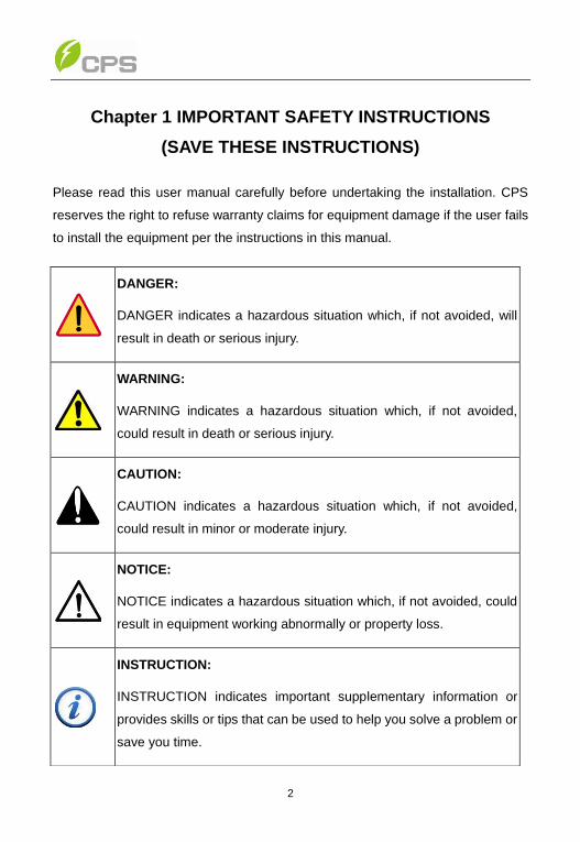
Chapter 1 IMPORTANT SAFETY INSTRUCTIONS
(SAVE THESE INSTRUCTIONS)
Please read this user manual carefully before undertaking the installation. CPS
reserves the right to refuse warranty claims for equipment damage if the user fails
to install the equipment per the instructions in this manual.
DANGER:
DANGER indicates a hazardous situation which, if not avoided, will
result in death or serious injury.
WARNING:
WARNING indicates a hazardous situation which, if not avoided,
could result in death or serious injury.
CAUTION:
CAUTION indicates a hazardous situation which, if not avoided,
could result in minor or moderate injury.
NOTICE:
NOTICE indicates a hazardous situation which, if not avoided, could
result in equipment working abnormally or property loss.
INSTRUCTION:
INSTRUCTION indicates important supplementary information or
provides skills or tips that can be used to help you solve a problem or
save you time.

3
Warnings and symbols in this document
Markings on the product
HIGH VOLTAGE:
The product works with high voltages. All work on the product
must only be performed as described in this document.
HOT SURFACE:
The equipment is designed to meet international safety
standards, but surfaces can become hot during operation. Do
not touch the heat sink or peripheral surfaces during or shortly
after operation.
EARTH GROUND:
This symbol marks the location of grounding terminal, which
must be securely connected to the earth through the PE
(protective earthing) cable to ensure operational safety.
DANGER:
Please disconnect the inverter from AC grid and PV modules before
opening the equipment. When the PV array is exposed to light, it
supplies DC voltage to this equipment. Make sure hazardous high
voltage and energy inside the equipment has been discharged.
Do not operate or maintain the inverter until at least 8 minutes after
disconnecting all sources from DC and AC sides.
WARNING:
All the installation and wiring connections should be performed only
by qualified technical personnel. Disconnect the inverter from PV
modules and the Power Grid before maintaining and operating the
equipment.

4
CAUTION:
Although designed to meet international safety standards, the
PV-Inverter can become hot during operation. Do not touch the heat
sink or peripheral surfaces during or shortly after operation.
CAUTION:
CPS SCA3/4/5KTL series inverter is approx 38kg (84lbs).
Please Check the mounting bracket again before the PV Inverter is
hung on to the bracket. At least 2 people are required for this
procedure due to the weight of the inverter.
NOTICE:
This inverter is designed to connect AC power only to the public grid.
Do not connect the AC output of this equipment directly to any
private AC power equipment.
INSTRUCTION:
Please check with your local electricity supply company before
selecting the grid connection standard.
Putting the inverter into operation before the overall system complies
with the national rules and safety regulation of the application is not
permitted.
5
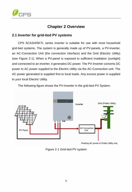
Chapter 2 Overview
2.1 Inverter for grid-tied PV systems
CPS SCA3/4/5KTL series inverter is suitable for use with most household
grid-tied systems. The system is generally made up of PV-panels, a PV-inverter,
an AC-Connection Unit (the connection Interface) and the Grid (Electric Utility)
(see Figure 2-1). When a PV-panel is exposed to sufficient irradiation (sunlight)
and connected to an inverter, it generates DC power. The PV-Inverter converts DC
power to AC power supplied to the Electric Utility via the AC-Connection unit. The
AC power generated is supplied first to local loads. Any excess power is supplied
to your local Electric Utility.
The following figure shows the PV-Inverter in the grid-tied PV System:
Figure 2-1 Grid-tied PV system
6
2.2 Product features
Lead-free, RoHS compliant
Up to 97.5% peak conversion efficiency
Dual MPPT design
NEMA 3R outdoor rated enclosure
2x16 LCD display
Single phase, 208V L-L or 240V L-L
Compact design
High reliability with a standard 10 year warranty
Easy operation
Maintenance free operation
Remote Communications Interface
Complies with IEEE1547: 2003, IEEE1547.1: 2005 Standards
Integrated GFDI on PV arrays
7
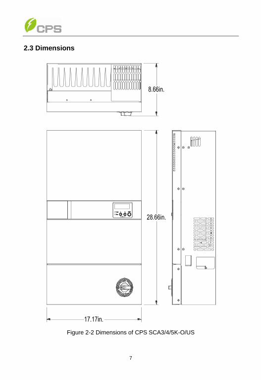
2.3 Dimensions
Figure 2-2 Dimensions of CPS SCA3/4/5K-O/US
8
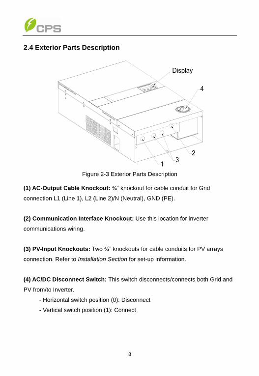
2.4 Exterior Parts Description
Figure 2-3 Exterior Parts Description
(1) AC-Output Cable Knockout: ¾” knockout for cable conduit for Grid
connection L1 (Line 1), L2 (Line 2)/N (Neutral), GND (PE).
(2) Communication Interface Knockout: Use this location for inverter
communications wiring.
(3) PV-Input Knockouts: Two ¾” knockouts for cable conduits for PV arrays
connection. Refer to Installation Section for set-up information.
(4) AC/DC Disconnect Switch: This switch disconnects/connects both Grid and
PV from/to Inverter.
- Horizontal switch position (0): Disconnect
- Vertical switch position (1): Connect
9
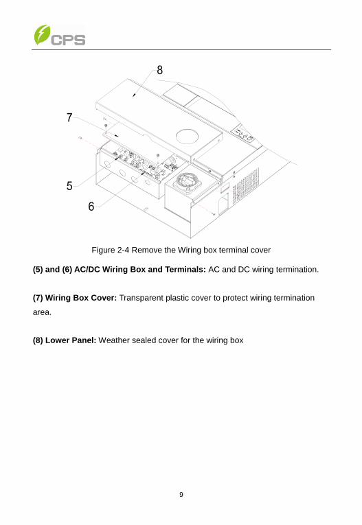
Figure 2-4 Remove the Wiring box terminal cover
(5) and (6) AC/DC Wiring Box and Terminals: AC and DC wiring termination.
(7) Wiring Box Cover: Transparent plastic cover to protect wiring termination
area.
(8) Lower Panel: Weather sealed cover for the wiring box
10
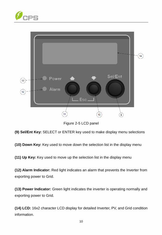
Figure 2-5 LCD panel
(9) Sel/Ent Key: SELECT or ENTER key used to make display menu selections
(10) Down Key: Key used to move down the selection list in the display menu
(11) Up Key: Key used to move up the selection list in the display menu
(12) Alarm Indicator: Red light indicates an alarm that prevents the Inverter from
exporting power to Grid.
(13) Power Indicator: Green light indicates the inverter is operating normally and
exporting power to Grid.
(14) LCD: 16x2 character LCD display for detailed Inverter, PV, and Grid condition
information.
11
Chapter 3 Installation
Please read the following installation instructions carefully and install the product
step-by-step.
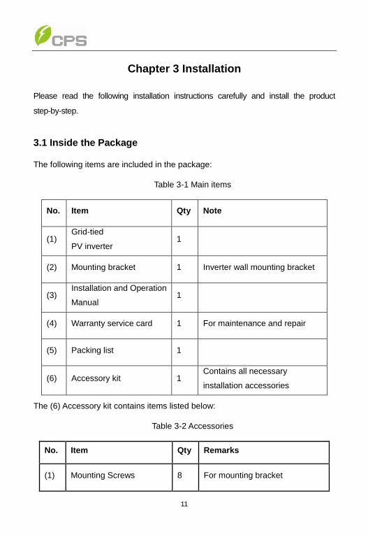
3.1 Inside the Package
The following items are included in the package:
Table 3-1 Main items
No. Item Qty Note
(1) Grid-tied
PV inverter 1
(2) Mounting bracket 1 Inverter wall mounting bracket
(3) Installation and Operation
Manual 1
(4) Warranty service card 1 For maintenance and repair
(5) Packing list 1
(6) Accessory kit 1 Contains all necessary
installation accessories
The (6) Accessory kit contains items listed below:
Table 3-2 Accessories
No. Item Qty Remarks
(1) Mounting Screws 8 For mounting bracket

12
(2) Snap Bushings/anchors 8 For mounting bracket
(3) Safety-lock screws 1 To secure the inverter
(4) Mounting plate of the data
logger 1 For optional comm. card
(5) Ring terminals 13 For wire connections
(6) Cable gland 1 For communication ports
(7) Seal pin 2 For cable gland holes
3.2 Basic requirements
Check that the product environmental specifications (protection degree,
operating temperature range, humidity and altitude, etc) meet the
requirements of the specific project location;
Make sure that the power grid voltage is within normal range;
Ensure that the local electricity supply authority has granted permission to
connect to the grid;
Installation personnel must be qualified electricians or people who have
received professional training;
Sufficient space is provided to allow the inverter cooling system to operate
normally;
Install the inverter away from flammable and explosive substances;
Avoid installing the inverter in locations that exceed the temperature limits
specified in the inverter data sheet to limit undesirable power loss;
Do not install the inverter near an electromagnetic source which can
compromise the normal operation of electronic equipment;
13
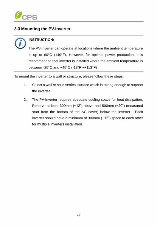
3.3 Mounting the PV-Inverter
To mount the inverter to a wall or structure, please follow these steps:
1. Select a wall or solid vertical surface which is strong enough to support
the inverter.
2. The PV-Inverter requires adequate cooling space for heat dissipation.
Reserve at least 300mm (~12”) above and 500mm (~20”) (measured
start from the bottom of the AC cover) below the inverter. Each
inverter should have a minimum of 300mm (~12”) space to each other
for multiple inverters installation.
INSTRUCTION:
The PV-Inverter can operate at locations where the ambient temperature
is up to 60C (140F). However, for optimal power production, it is
recommended that inverter is installed where the ambient temperature is
between -25C and +45C (-13F ~+113F)

14
Figure 3-1 Inverter mounting dimensions
NOTICE:
Inverter utilizes natural convection cooling for its heat sink. Mounting
the inverter in a horizontal position or having an obstruction on the
top of Inverter will result in overheating.

15
Figure 3-2 Mount the inverter correctly
16
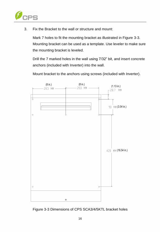
3. Fix the Bracket to the wall or structure and mount:
Mark 7 holes to fit the mounting bracket as illustrated in Figure 3-3.
Mounting bracket can be used as a template. Use leveler to make sure
the mounting bracket is leveled.
Drill the 7 marked holes in the wall using 7/32” bit, and insert concrete
anchors (included with Inverter) into the wall.
Mount bracket to the anchors using screws (included with Inverter).
Figure 3-3 Dimensions of CPS SCA3/4/5KTL bracket holes

17
4. Mount the PV-Inverter onto the base plate as illustrated in Figure 3-4.
Figure 3-4 Mount the inverter on the bracket
5. Secure the inverter to the bracket with M6 screw to hold the bottom of
inverter to keep the inverter from vibrating against the wall, as shown
in Figure 3-5.
Figure 3-5 Mounting clamp
18
3.4 Electrical installation
3.4.1 DC Connection
Connections from PV panels to the Inverter are made in the Inverter Wiring Box.
Cable type and size should be selected according to the following requirements:
Use Class 2 or Class 3 cable, with temperature rating of 194 °F (or 90 °C).
Wire size is from 12 AWG to 8 AWG.
1. Switch off circuit breaker in the main switch box to disconnect utility.
2. Cover PV panels to prevent from producing DC energy during installation.
3. Put AC/DC disconnect switch to “0” position (OFF).
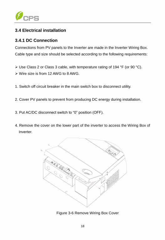
4. Remove the cover on the lower part of the inverter to access the Wiring Box of
Inverter.
Figure 3-6 Remove Wiring Box Cover

19
Figure 3-7 Remove Plastic Protective Cover
5. Configure single MPPT or dual MPPT
a. Single MPPT: This is not a typical configuration. Use a single MPPT if
the array design requires it. For example, an array design with 3 input
strings that would exceed the Maximum Input Current per MPPT
channel may have improved power output if the 3 input strings are
combined in a single MPPT. See Product Data Sheets for design
guidelines and specifications.
i. Connect jumper bar between P48 and P49 on wiring board.
20
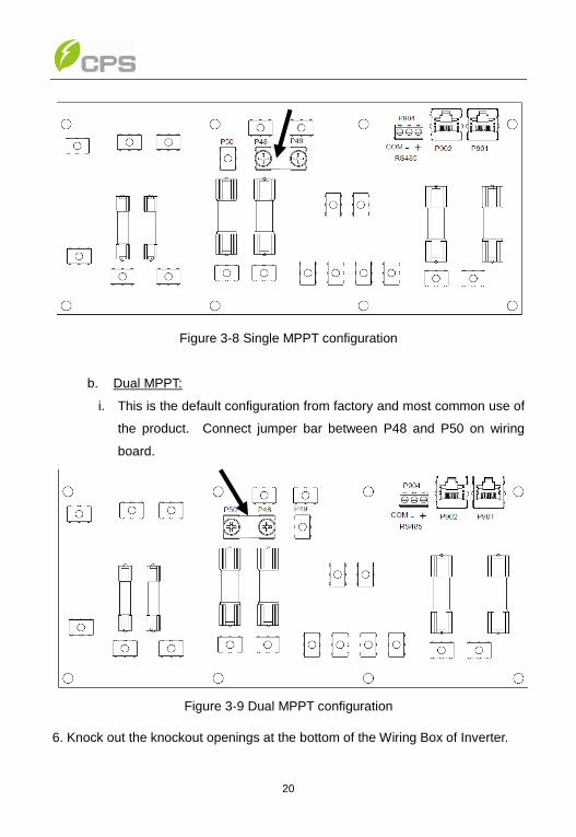
Figure 3-8 Single MPPT configuration
b. Dual MPPT:
i. This is the default configuration from factory and most common use of
the product. Connect jumper bar between P48 and P50 on wiring
board.
Figure 3-9 Dual MPPT configuration
6. Knock out the knockout openings at the bottom of the Wiring Box of Inverter.
21
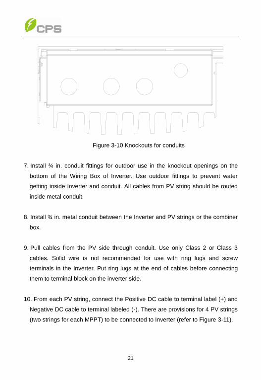
Figure 3-10 Knockouts for conduits
7. Install ¾ in. conduit fittings for outdoor use in the knockout openings on the
bottom of the Wiring Box of Inverter. Use outdoor fittings to prevent water
getting inside Inverter and conduit. All cables from PV string should be routed
inside metal conduit.
8. Install ¾ in. metal conduit between the Inverter and PV strings or the combiner
box.
9. Pull cables from the PV side through conduit. Use only Class 2 or Class 3
cables. Solid wire is not recommended for use with ring lugs and screw
terminals in the Inverter. Put ring lugs at the end of cables before connecting
them to terminal block on the inverter side.
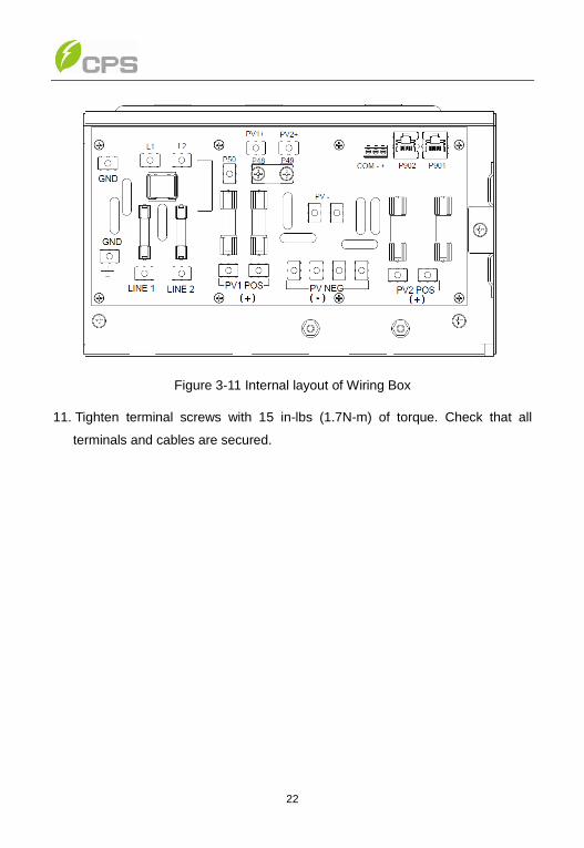
10. From each PV string, connect the Positive DC cable to terminal label (+) and
Negative DC cable to terminal labeled (-). There are provisions for 4 PV strings
(two strings for each MPPT) to be connected to Inverter (refer to Figure 3-11).
22
Figure 3-11 Internal layout of Wiring Box
11. Tighten terminal screws with 15 in-lbs (1.7N-m) of torque. Check that all
terminals and cables are secured.
23
3.4.2 AC Connection
1. Switch off circuit breaker in the main switch box to disconnect utility.
2. Put AC/DC disconnect switch to OFF position.
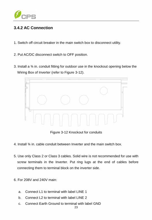
3. Install a ¾ in. conduit fitting for outdoor use in the knockout opening below the
Wiring Box of Inverter (refer to Figure 3-12).
Figure 3-12 Knockout for conduits
4. Install ¾ in. cable conduit between Inverter and the main switch box.
5. Use only Class 2 or Class 3 cables. Solid wire is not recommended for use with
screw terminals in the Inverter. Put ring lugs at the end of cables before
connecting them to terminal block on the inverter side.
6. For 208V and 240V main:
a. Connect L1 to terminal with label LINE 1
b. Connect L2 to terminal with label LINE 2
c. Connect Earth Ground to terminal with label GND
24
7. Tighten terminal screws with 15 in-lbs (1.7N-m) of torque. Check that all
terminals and cables are secured.
3.4.3 Wiring Checklist
(1) Measure the utility power quality of each phase. Make sure the waveform of
voltage is a pure sine wave without any harmonics right after your PV system is
completed. Performing the measurement when your PV system is at maximum
power generation is recommended.
(2) If harmonics exist in your PV system, one or more of capacitors or AC filters
DANGER:
High voltages exist between terminals of PV panels when Panel is
exposed to sufficient irradiation. Exposed terminals of the PV-Panel
can cause electric shock. Avoid making physical contact with those
parts of the device.
NOTICE:
Before connecting PV-Panels to DC terminals, make sure the polarity
of each connection is correct. An incorrect connection could
permanently damage the device.
NOTICE:
Perform an AC power quality measurement after the PV system is
completed to check for any abnormal AC grid condition or harmonics.
NOTICE:
Any degradation or damage of the device due to nonperformance of
the AC grid (non-compliance with IEEE standards) or uncontrolled
power quality is out of the scope of warranty.

25
may be required to install between the Inverter(s) and the utility isolation
transformer until a pure sine wave is achieved. Any such action must be done by
qualified personal and in conjunction with local electrical authorities. Specific
guidance is outside the scope of this document.
3.4.4 Communication Interface
3.4.4.1 Standard RS-485 Communication
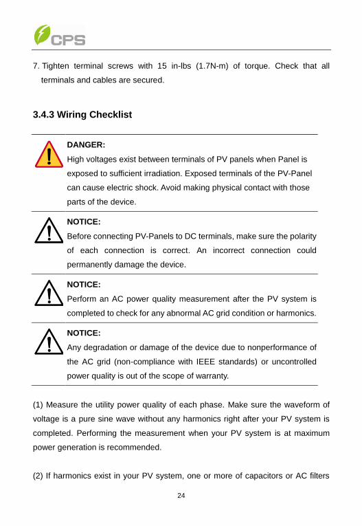
The inverter has integrated RS-485 communications capability. The connection of
RS-485 communication are made in the wiring box, as shown in Figure 3-13:
Figure 3-13 Internal communication structure
1. RS-485 +: communication pin (also called RS-485 A)
2. RS-485 -: communication pin (also called RS*485 B)
3. RS-485 COM: common ground for communication signal
26
Figure 3-14 Communication connector on wiring board
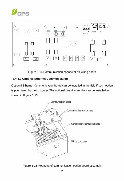
3.4.4.2 Optional Ethernet Communication
Optional Ethernet Communication board can be installed in the field if such option
is purchased by the customer. The optional board assembly can be installed as
shown in Figure 3-15.
Figure 3-15 Mounting of communication option board assembly

27
Chapter 4 Commissioning
4.1 Start Up
The inverter will start up when the following conditions are satisfied:
1. Grid voltage and frequency are within nominal setting.
o 240V settings: Grid voltage at start-up must be between 216V
and 254V
o 208V settings: Grid voltage at start-up must be between 187V
and 220V
o Grid Frequency must be between 59.5Hz to 60.3Hz
2. PV array voltage is greater than 200V on any one of two MPPT channels.
4.2 First-Time Start Up
During first-time start up, the inverter will prompt installers to choose various
setting options to match grid conditions and to configure inverter’s communication
options.
The installer can go back to the configuration screens by pressing all three
buttons (Up, Down, and Enter) at the same time for 5 seconds. After holding
these keys for 5 seconds, the inverter will stop exporting power to the grid and
allow the installer to choose the setup options as if it were the first-time start up.
INSTRUCTION:
After first-time start up, the inverter will not go through these
configuration steps in subsequence start-ups. Inverter will go directly
through start up sequence.
28
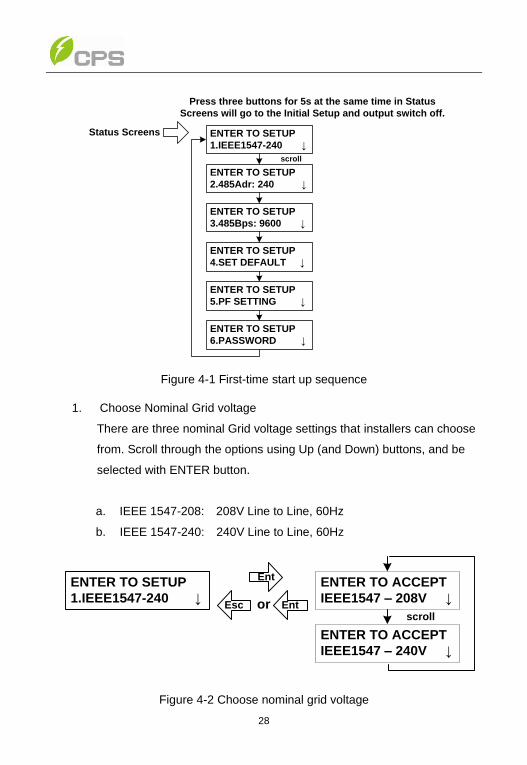
Press three buttons for 5s at the same time in Status
Screens will go to the Initial Setup and output switch off.
Status Screens ENTER TO SETUP
1.IEEE1547-240 ↓
ENTER TO SETUP
2.485Adr: 240 ↓
ENTER TO SETUP
3.485Bps: 9600 ↓
ENTER TO SETUP
4.SET DEFAULT ↓
ENTER TO SETUP
5.PF SETTING ↓
ENTER TO SETUP
6.PASSWORD ↓
scroll
Figure 4-1 First-time start up sequence
1. Choose Nominal Grid voltage
There are three nominal Grid voltage settings that installers can choose
from. Scroll through the options using Up (and Down) buttons, and be
selected with ENTER button.
a. IEEE 1547-208: 208V Line to Line, 60Hz
b. IEEE 1547-240: 240V Line to Line, 60Hz
ENTER TO ACCEPT
IEEE1547 – 208V ↓
ENTER TO ACCEPT
IEEE1547 – 240V ↓
ENTER TO SETUP
1.IEEE1547-240 ↓
Ent
Esc or Entscroll
Figure 4-2 Choose nominal grid voltage

29
2. Choose Inverter RS485 address
This is the unique Modbus address of the inverter within a network of
inverters and communication devices. The address can be any number
between 0 and 99.
ENTER TO SETUP
2.485Adr: 240 ↓
Ent
Esc or Ent
ENTER TO ACCEPT
485Adr:240 ↕
Figure 4-3 Choose Inverter RS485 address
3. Choose Inverter Baud rate
Choose the communication Baud rate to match the rate of the device
(gateway) that connects to inverter. The default Baud rate is 9600.
1. Press Up and Down key to change number for each digit.
2. Press Enter key to accept the value for each digit. The display will
automatically jump to the next digit for entry.
3. After the last digit, Enter key will move to the next setting item.
ENTER TO ACCEPT
485bps: xxxx ↕
ENTER TO SETUP
3.485Bps: 9600 ↓
Ent
Esc or Ent
Figure 4-4 Choose Inverter baud rate
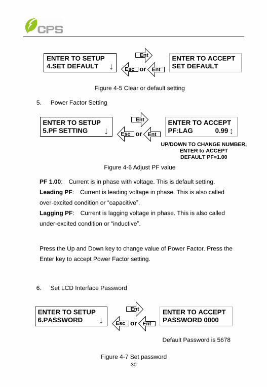
4. Set Default
INSTRUCTION:
No two Inverters in the same network can share the same address.
30
ENTER TO ACCEPT
SET DEFAULT
ENTER TO SETUP
4.SET DEFAULT ↓
Ent
Esc or Ent
Figure 4-5 Clear or default setting
5. Power Factor Setting
ENTER TO SETUP
5.PF SETTING ↓
Ent
Esc or Ent
ENTER TO ACCEPT
PF:LAG 0.99 ↕
UP/DOWN TO CHANGE NUMBER,
ENTER to ACCEPT
DEFAULT PF=1.00
Figure 4-6 Adjust PF value
PF 1.00: Current is in phase with voltage. This is default setting.
Leading PF: Current is leading voltage in phase. This is also called
over-excited condition or “capacitive”.
Lagging PF: Current is lagging voltage in phase. This is also called
under-excited condition or “inductive”.
Press the Up and Down key to change value of Power Factor. Press the
Enter key to accept Power Factor setting.
6. Set LCD Interface Password
ENTER TO SETUP
6.PASSWORD ↓
Ent
Esc or Ent
ENTER TO ACCEPT
PASSWORD 0000
Default Password is 5678
Figure 4-7 Set password

31
7. Exit Configuration
When all selections have been properly selected, the installer can go to
START INVERTER to enable the inverter to start.
1. Press Enter key to go into the item
2. Press Enter key to exit the Setup Menu, and proceed to start up Inverter
ENTER TO ACCEPT
ENTER TO START?
ENTER TO SETUP
7.START INVERTE ↓
Ent
Esc
Figure 4-8 Complete configuration and start up Inverter
Display will show the Self Test screen during the Start-up Sequence. Press
ESC combination will send the display to Information Screens.
4.3 Start-Up Sequence
The inverter will go through a sequence of safety checks before it starts exporting
power. It takes the inverter about 5 minutes to go through the whole Start-Up
Sequence.
SELFTEST 5.0KW
>>>
Figure 4-9 Inverter self-test
The following are Self-Check items that the inverter goes through:
1. Check Ground Fault operation of internal circuit and check fault current
on PV array. Ground fault current is also monitored continuously during
operation. A Ground fault will stop the inverter from exporting power to
the grid.
2. Check Impedance from the Positive and Negative terminals of the PV
array to Earth Ground.

32
3. Check various internal components.
4. Check the disconnecting relays between Inverter and Grid.
If any of these tests fails, the inverter will display a fault message about the failure
and will not connect to grid. If all Self-Test items pass, the inverter will connect
and export power to Grid.

33
Chapter 5 User Interface
5.1 Normal Operation and Display Menu
5.1.1 Status Screens
After the inverter begins exporting power to the grid, the LCD display
automatically scrolls through various information screens, displaying grid and PV
array information. The Up and Down keys can be used to go to specific
information. After 2 minutes, the display will resume scrolling.
Etoday 12345kWh
Power 1234W
Etotal 12345kWh
Runtime 2345h
Vgrid 240V
Igrid 14.5A
Vpv1 434.5V
Ipv1 15.5A
Vpv2 400.0V
Ipv2 20.0A
Freq. 60.00Hz
Pfactor 1.000
scroll
Status Screens
UP/DOWN TO CHANGE
Figure 5-1 Inverter status screens
NOTE: LCD display will switch off after 2 minutes. Pressing any key will bring the
screen back.
34
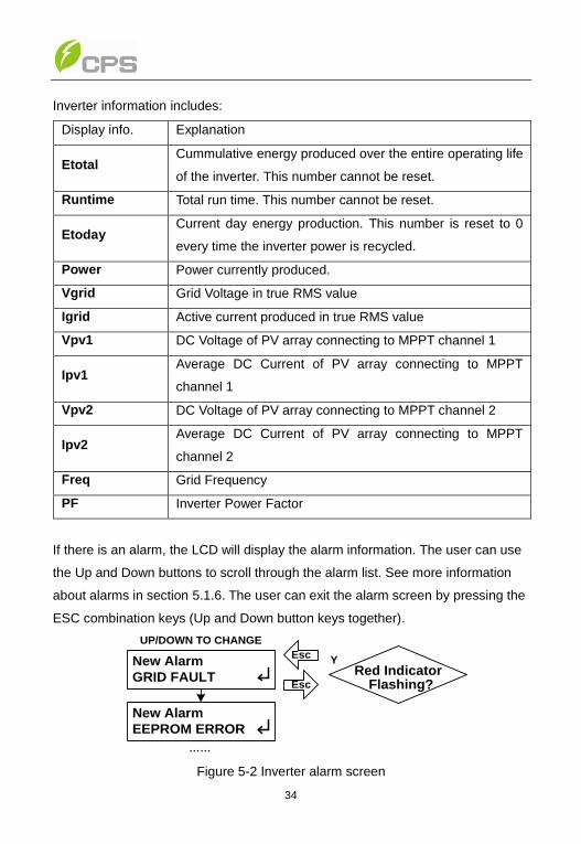
Inverter information includes:
Display info. Explanation
Etotal Cummulative energy produced over the entire operating life
of the inverter. This number cannot be reset.
Runtime Total run time. This number cannot be reset.
Etoday Current day energy production. This number is reset to 0
every time the inverter power is recycled.
Power Power currently produced.
Vgrid Grid Voltage in true RMS value
Igrid Active current produced in true RMS value
Vpv1 DC Voltage of PV array connecting to MPPT channel 1
Ipv1 Average DC Current of PV array connecting to MPPT
channel 1
Vpv2 DC Voltage of PV array connecting to MPPT channel 2
Ipv2 Average DC Current of PV array connecting to MPPT
channel 2
Freq Grid Frequency
PF Inverter Power Factor
If there is an alarm, the LCD will display the alarm information. The user can use
the Up and Down buttons to scroll through the alarm list. See more information
about alarms in section 5.1.6. The user can exit the alarm screen by pressing the
ESC combination keys (Up and Down button keys together).
New Alarm
GRID FAULT
Esc
Red IndicatorFlashing?
Y
Esc
……
New Alarm
EEPROM ERROR
UP/DOWN TO CHANGE
Figure 5-2 Inverter alarm screen
35
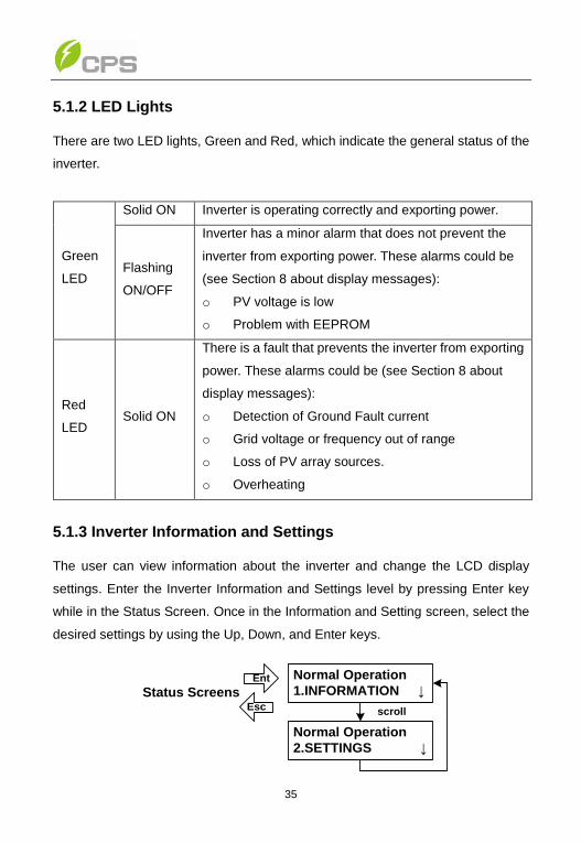
5.1.2 LED Lights
There are two LED lights, Green and Red, which indicate the general status of the
inverter.
Green
LED
Solid ON Inverter is operating correctly and exporting power.
Flashing
ON/OFF
Inverter has a minor alarm that does not prevent the
inverter from exporting power. These alarms could be
(see Section 8 about display messages):
o PV voltage is low
o Problem with EEPROM
Red
LED Solid ON
There is a fault that prevents the inverter from exporting
power. These alarms could be (see Section 8 about
display messages):
o Detection of Ground Fault current
o Grid voltage or frequency out of range
o Loss of PV array sources.
o Overheating
5.1.3 Inverter Information and Settings
The user can view information about the inverter and change the LCD display
settings. Enter the Inverter Information and Settings level by pressing Enter key
while in the Status Screen. Once in the Information and Setting screen, select the
desired settings by using the Up, Down, and Enter keys.
Normal Operation
1.INFORMATION ↓
Normal Operation
2.SETTINGS ↓
Ent
Esc scroll
Status Screens
36
Figure 5-3 Information and settings
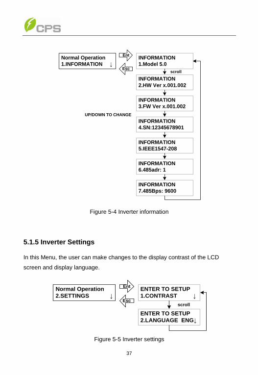
5.1.4 Inverter Information
In this screen menu, User can review the settings of Inverter. Information includes:
1. Inverter model rating
2. Inverter hardware revision
3. Inverter firmware revision
4. Inverter serial number
5. Inverter Grid voltage and frequency configuration
6. Inverter communication address
7. Inverter communication Baud rate
INSTRUCTION:
Setting levels cannot be changed in this menu level. User can make
change by going to First-Time Start-Up Setting (see Section 4.2) by
pressing all three keys for 5 seconds.
37
INFORMATION
1.Model 5.0
INFORMATION
2.HW Ver x.001.002
INFORMATION
3.FW Ver x.001.002
INFORMATION
4.SN:12345678901
INFORMATION
5.IEEE1547-208
scroll
INFORMATION
6.485adr: 1
INFORMATION
7.485Bps: 9600
Ent
Esc
Normal Operation
1.INFORMATION ↓
UP/DOWN TO CHANGE
Figure 5-4 Inverter information
5.1.5 Inverter Settings
In this Menu, the user can make changes to the display contrast of the LCD
screen and display language.
ENTER TO SETUP
2.LANGUAGE ENG↓
ENTER TO SETUP
1.CONTRAST ↓
scroll
Ent
Esc
Normal Operation
2.SETTINGS ↓
Figure 5-5 Inverter settings

38
Contrast:
There are 5 levels of contrast that user can select to make LCD characters easier
to view in different light and temperature conditions.
1. Use Enter key to go into the contrast change screen.
2. Use Up and Down button to make change to contrast of LCD screen.
3. Use Enter key to accept the change.
4. Use ESC key combination to go back.
ENTER TO SETUP
1.CONTRAST ↓
5 Levels of contrast: 1-5
Ent
Esc
ENTER TO ACCEPT
CONTRAST: 3 ↓or Ent
Figure 5-6 Contrast settings
Language:
There are two languages, English and German, from which user can select as the
display menu language.
ENTER TO SETUP
2.LANGUAGE ENG↓
Ent
Esc or Ent
ENTER TO ACCEPT
LANGUAGE ENG ↓
Figure 5-7 Language settings

39
5.1.6 Display Messages
Monitoring Parameters
Explanation
Etotal: xxxxx kWhr Accumulated energy exporting to Grid over the lifetime of Inverter in kW-Hr
Runtime: xxxxxx Hr Accumulated runtime of Inverter. (5 digit numbers)
Etoday: xxxxx WHr Accumulated energy exporting to Grid in that day
Power: xxxx W Instantaneous power exporting to grid
GridV: xxx.x V Grid RMS voltage in Volt
GridI: xx.xx A Grid RMS current in Amp
PV1V Voltage of PV array number 1
PV1 I Current of PV array number 1
PV2 V Voltage of PV array number 2
PV2 I Current of PV array number 2
Freq: xx.xx Hz Grid frequency in Hertz
System Fault Explanation
PV IMPEDANCE LOW Resistance from either PV inputs to Earth Ground is lower than 700 kOhm
ISOLATION FAULT Disconnecting relays between Inverter and Grid do not work properly
INPUT GND FAULT Fault current from PV arrays to Earth Ground
INTERNAL FAULT Failure of self-test on internal converters in Inverter
GRID FAULT Utility is not available
PV VOLTAGE HIGH PV array voltage is higher than PV operating range.
40
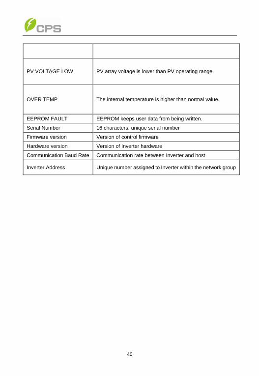
PV VOLTAGE LOW PV array voltage is lower than PV operating range.
OVER TEMP The internal temperature is higher than normal value.
EEPROM FAULT EEPROM keeps user data from being written.
Serial Number 16 characters, unique serial number
Firmware version Version of control firmware
Hardware version Version of Inverter hardware
Communication Baud Rate Communication rate between Inverter and host
Inverter Address Unique number assigned to Inverter within the network group

41
Chapter 6 Preventative Maintenance
6.1 Troubleshooting
The PV-Inverter requires very little maintenance. When unexpected situation
occurs, please refer to the following table for quick troubleshooting before
contacting your local service. The following table lists common fault messages
and ways to cope with the fault or error.
System Fault Explanation Action / Fault Clearance
PV
IMPEDANCE
LOW
Resistance from either PV inputs
to Earth Ground is lower than
700 kOhm
Check impedance from PV arrays to Earth
Ground. PV arrays may need cleaning or
drying.
Need to recycle power to Inverter to clear
fault. Inverter will test impedance again
during Start-up Sequence
ISOLATION
FAULT
Disconnecting relays between
Inverter and Grid do not work
properly
Need to recycle power to Inverter. Inverter
will retest relays during Start-up sequence.
If Fault Message occurs again, contact your
local service.
INPUT GND
FAULT
Fault current from PV arrays to
Earth Ground
Check impedance from PV arrays to Earth
Ground. PV arrays may need cleaning or
drying.
Need to recycle power to Inverter.
INTERNAL
FAULT
Failure of self-test on internal
converters in Inverter
Need to recycle power to Inverter. Inverter
will retest relays during Start-up sequence.
If Fault Message occurs again, contact your
local service.
42
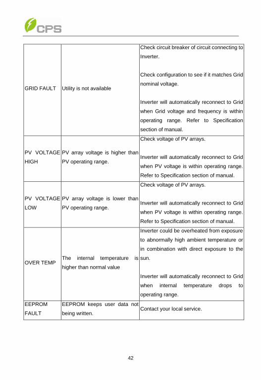
GRID FAULT Utility is not available
Check circuit breaker of circuit connecting to
Inverter.
Check configuration to see if it matches Grid
nominal voltage.
Inverter will automatically reconnect to Grid
when Grid voltage and frequency is within
operating range. Refer to Specification
section of manual.
PV VOLTAGE
HIGH
PV array voltage is higher than
PV operating range.
Check voltage of PV arrays.
Inverter will automatically reconnect to Grid
when PV voltage is within operating range.
Refer to Specification section of manual.
PV VOLTAGE
LOW
PV array voltage is lower than
PV operating range.
Check voltage of PV arrays.
Inverter will automatically reconnect to Grid
when PV voltage is within operating range.
Refer to Specification section of manual.
OVER TEMP The internal temperature is
higher than normal value
Inverter could be overheated from exposure
to abnormally high ambient temperature or
in combination with direct exposure to the
sun.
Inverter will automatically reconnect to Grid
when internal temperature drops to
operating range.
EEPROM
FAULT
EEPROM keeps user data not
being written. Contact your local service.
43
6.2 General maintenance
Although the PV-Inverter is designed to be maintenance free, the following regular
inspections would help to ensure the PV Inverter operation at optimal
performance level.
(1) Clean any debris that may settle on heat-sink on the back of the unit.
(2) Inspect Grid connection and PV connection. Re-torque terminal screws.
(3) Check the inverter and cables for any signs of external damage. Contact your
local service immediately if you find any defects. Do not carry out any repairs on
your own.
WARNING:
All the installation and wiring connections should be performed only by
qualified technical personnel. Disconnect the inverter from PV modules
and the Power Grid before maintaining and operating the equipment.
44
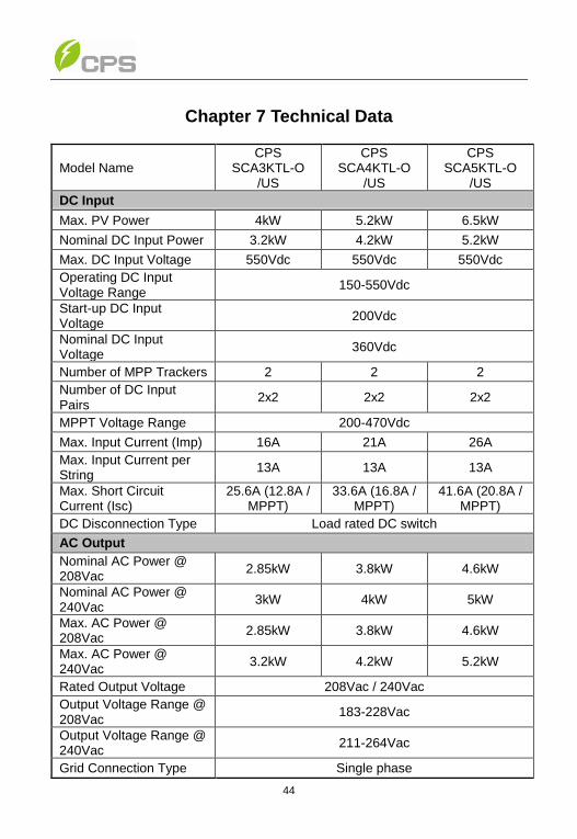
Chapter 7 Technical Data
Model Name CPS
SCA3KTL-O /US
CPS SCA4KTL-O
/US
CPS SCA5KTL-O
/US
DC Input
Max. PV Power 4kW 5.2kW 6.5kW
Nominal DC Input Power 3.2kW 4.2kW 5.2kW
Max. DC Input Voltage 550Vdc 550Vdc 550Vdc
Operating DC Input Voltage Range
150-550Vdc
Start-up DC Input Voltage
200Vdc
Nominal DC Input Voltage
360Vdc
Number of MPP Trackers 2 2 2
Number of DC Input Pairs
2x2 2x2 2x2
MPPT Voltage Range 200-470Vdc
Max. Input Current (Imp) 16A 21A 26A
Max. Input Current per String
13A 13A 13A
Max. Short Circuit Current (Isc)
25.6A (12.8A / MPPT)
33.6A (16.8A / MPPT)
41.6A (20.8A / MPPT)
DC Disconnection Type Load rated DC switch
AC Output
Nominal AC Power @ 208Vac
2.85kW 3.8kW 4.6kW
Nominal AC Power @ 240Vac
3kW 4kW 5kW
Max. AC Power @ 208Vac
2.85kW 3.8kW 4.6kW
Max. AC Power @ 240Vac
3.2kW 4.2kW 5.2kW
Rated Output Voltage 208Vac / 240Vac
Output Voltage Range @ 208Vac
183-228Vac
Output Voltage Range @ 240Vac
211-264Vac
Grid Connection Type Single phase
45
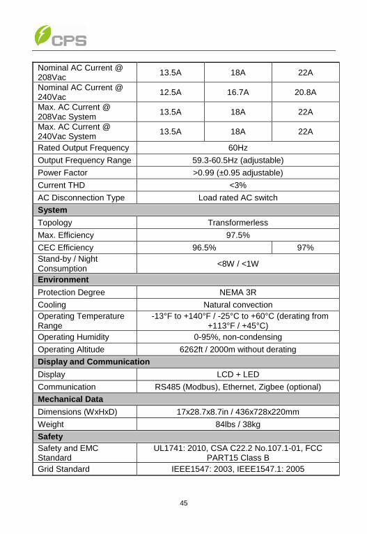
Nominal AC Current @ 208Vac
13.5A 18A 22A
Nominal AC Current @ 240Vac
12.5A 16.7A 20.8A
Max. AC Current @ 208Vac System
13.5A 18A 22A
Max. AC Current @ 240Vac System
13.5A 18A 22A
Rated Output Frequency 60Hz
Output Frequency Range 59.3-60.5Hz (adjustable)
Power Factor >0.99 (±0.95 adjustable)
Current THD <3%
AC Disconnection Type Load rated AC switch
System
Topology Transformerless
Max. Efficiency 97.5%
CEC Efficiency 96.5% 97%
Stand-by / Night Consumption
<8W / <1W
Environment
Protection Degree NEMA 3R
Cooling Natural convection
Operating Temperature Range
-13°F to +140°F / -25°C to +60°C (derating from +113°F / +45°C)
Operating Humidity 0-95%, non-condensing
Operating Altitude 6262ft / 2000m without derating
Display and Communication
Display LCD + LED
Communication RS485 (Modbus), Ethernet, Zigbee (optional)
Mechanical Data
Dimensions (WxHxD) 17x28.7x8.7in / 436x728x220mm
Weight 84lbs / 38kg
Safety
Safety and EMC Standard
UL1741: 2010, CSA C22.2 No.107.1-01, FCC PART15 Class B
Grid Standard IEEE1547: 2003, IEEE1547.1: 2005

46
Chapter 8 Limited Warranty
The warranty policy of this product is specified in the contract; otherwise, the
warranty period is 10 years. For service, Chint Power Systems America will
provide local support. For Warranty terms, please refer to the CPS America
standard warranty policy in place at time of purchase.
8.1 Disposal
The dealer or installers should remove the PV Inverter from the array and contact
the supplier for disposal instructions.
The inverter must not be disposed of with the household
waste.
Dispose of the PV Inverter at the end of its service life should
be done in accordance with the disposal regulations for electronic waste which
apply at the installation site at that time.
8.2 Contact Information
Should you have technical problems concerning this product, please contact our
Service line.
We require the following information in order to provide you with the necessary
assistance:
• Inverter type
• Serial number of the PV Inverter
• Type and number of PV panel connected
• Fault message
• Communication method