pv grid tie inverter solis three phase invertersolis three phase series pv inverters is able to...
TRANSCRIPT
PV Grid Tie Inverter
Installation and Operation Manual
Ver 1.4
Solis Three Phase Inverter
2016, Ningbo Ginlong Technologies Co., LtdC
Ningbo Ginlong Technologies Co., Ltd.
No. 57 Jintong Road, Binhai Industrial Park, Xiangshan, Ningbo,
Zhejiang, 315712, P.R.China.
Tel: +86 (0)574 6578 1806
Fax: +86 (0)574 6578 1606
If you encounter any problem on the inverter, please find out the inverter S/N
and contact us, we will try to respond to your question ASAP.
For model Solis-20K, Solis-25K, Solis-30K,Solis-36K-HV,
Solis-40K-HV
Content
.1.
2.3 Notice For Use
3. Overview
3.1 Inverter Interface Instructions
3.2 LED Status Indicator Light
3.3 Keypad
3.4 LCD
4. Product handing and storage
4.1 Product handing
4.2 Product storage
3
5
5
5
6
7
7
7
8
8
9
9
10
1. Introduction
2. Safety Instruction
2.1 Safety Symbols
2.2 General Safety Instruction
……………………………………………………………
……………………………………………………
…………………………………………………
……………………………………
…………………………………………………
……………………………………………………………
…………………………
…………………………………
………………………………………………………
…………………………………
41.2 Packaging List …………………………………………………
……………………………………………………………
41.1 Induction …………………………………………………………
………………………………………………
………………………………………………
5. Installation
5.1 Select a Location for the Inverter
5.2 Mounting the Inverter
5.3 Electrical Connections
6. Start and Stop
6.1 Start the Inverter
6.2 Stop the Inverter
11
11
13
15
25
25
25
…………………………………………………………
………………………
………………………………………
……………………………………
……………………………………………………
………………………………………………
5.3.2 DC side connection
5.3.3 AC side connection
18
20
5.3.4 Inverter monitoring connection 22
…………………………………
……………………
…………………………………
7. General Operation 26………………………………………………
………………………………………………
7.1 Interface 26………………………………………………………
5.3.1 Protective ground wire connection(PE) 16…………
.2. .3.
1. Introduction
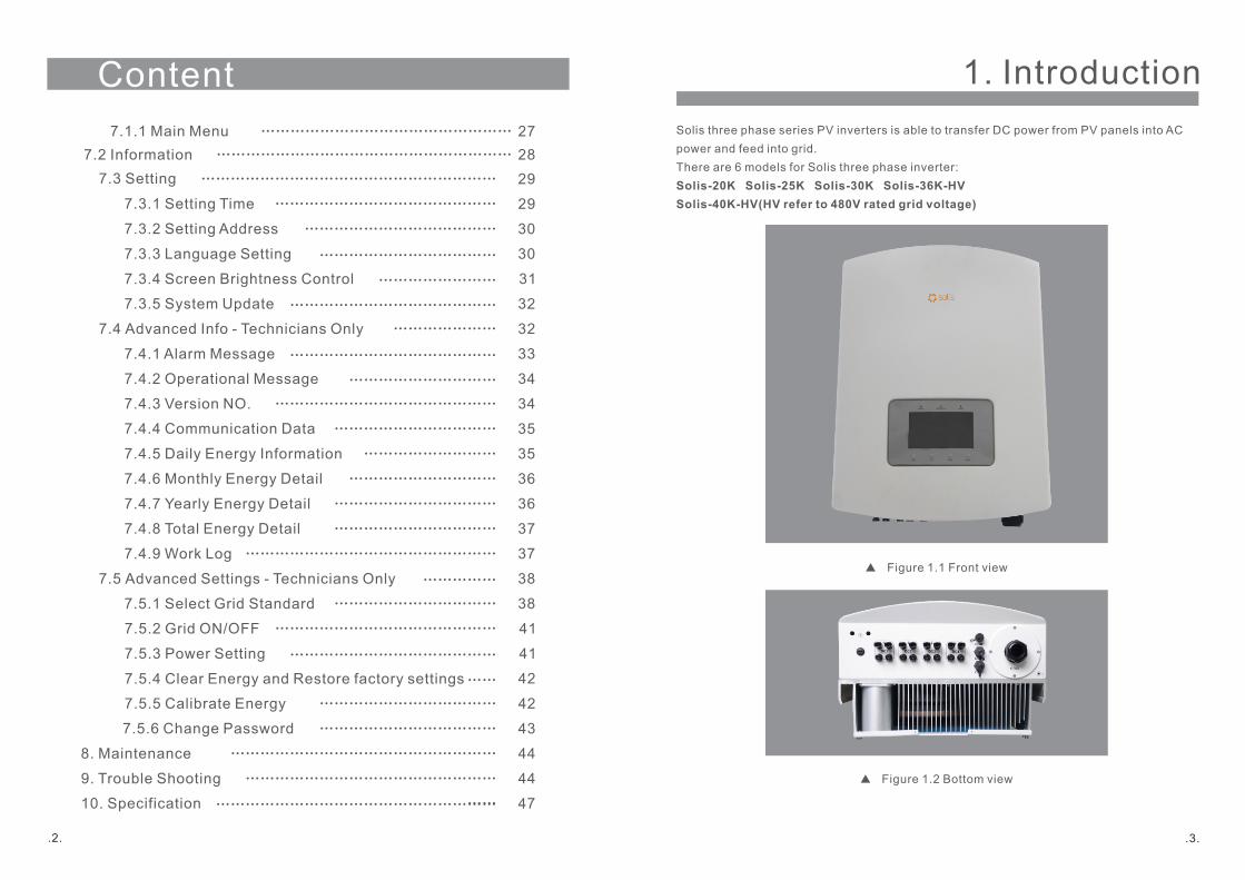
Solis three phase series PV inverters is able to transfer DC power from PV panels into AC
power and feed into grid.
There are 6 models for Solis three phase inverter:
Solis-20K Solis-25K Solis-30K Solis-36K-HV
Solis-40K-HV(HV refer to 480V rated grid voltage)
Figure 1.1 Front view
Figure 1.2 Bottom view
7.3 Setting
7.3.1 Setting Time
7.3.2 Setting Address
7.4 Advanced Info - Technicians Only
7.4.1 Alarm Message
7.4.3 Version NO.
7.4.4 Communication Data
7.4.5 Daily Energy Information
7.5 Advanced Settings - Technicians Only
7.5.1 Select Grid Standard
7.5.2 Grid ON/OFF
8. Maintenance
9. Trouble Shooting
10. Specification
29
29
30
32
33
34
35
35
38
38
41
44
44
47
7.4.2 Operational Message 34
7.5.3 Power Setting 41
……………………………………………………
………………………………………
…………………………………
………………………………………
……………………………
……………………………
………………………………………………
……………………………………………
……………………………………
7.3.3 Language Setting
7.3.4 Screen Brightness Control
30
31
7.3.5 System Update 32
7.4.7 Yearly Energy Detail
7.4.8 Total Energy Detail
7.4.9 Work Log
36
37
37
7.4.6 Monthly Energy Detail 36
……………………………
……………………………………………
……………………………
…………………………
………………………
7.5.5 Calibrate Energy
42
42
7.5.6 Change Password 43
………………………………
………………………………
……
………………………………
……………………………………
……………………
…………………
……………………………………
…………………………
Content
7.5.4 Clear Energy and Restore factory settings
……………
………………………………………
……
…………………………………………………
7.2 Information 28……………………………………………………
7.1.1 Main Menu 27……………………………………………

2. Safety Instruction
.5.
2.1Safety Symbols
Safety symbols used in this manual, which highlight potential safety risks and important
safety information, are listed as follows:
CAUTION:
CAUTION, RISK OF ELECTRIC SHOCK symbol indicates important safety
instructions, which if not correctly followed, could result in electric shock.
CAUTION:
CAUTION, HOT SURFACE symbol indicates safety instructions, which if not
correctly followed, could result in burns.
NOTE:
NOTE symbol indicates important safety instructions, which if not correctly
followed could result in some damage or the destruction of the inverter.
WARNING:
WARNING symbol indicates important safety instructions, which if not correctly
followed, could result in serious injury or death.
Improper use may result in potential electric shock hazards or burns. This manual contains
important instructions that should be followed during installation and maintenance. Please
read these instructions carefully before use and keep them for future reference.
2.2 General Safety Instructions
WARNING:
Electrical installations must be done in accordance with the local and national
regulatory and electrical safety standards.
WARNING:
DC input and AC output must be electrically isolated before operation.
DO NOT connect PV array positive (+) or negative (-) to the ground. To do
so may cause serious damage to the inverter.
. .4
1.2 Packaging List
Please check according to following table, to see whether all the parts were included in the
packaging:
Part NO. Description Number
PV grid tie Inverter
Wall mounting bracket
Locking screws
Expansion screws
DC connectors
Adhesive tape set
Table 1.1 Material list
8 pairs
Rj45 connector 2 set
1. Introduction
1
2
3
4
5
6
7
1
1
2
3
1
PV Grid Tie Inverter
Installation and Operation Manual
Ver 1.4
Solis Three Phase Inverter
2016, Ningbo Ginlong Technologies Co., LtdC
For model Solis-20K, Solis-25K, Solis-30K, Solis-36K-HV,
Solis-40K-HV
AC M4 washer8 1
98
Manual9 1
3. Overview
.6. .7.
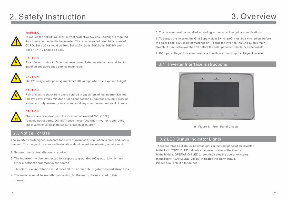
3.1 Inverter Interface Instructions
Figure 3.1 Front Panel Display
3.2 LED Status Indicator Lights
There are three LED status indicator lights in the front panel of the inverter.
In the Left: POWER LED indicates the power status of the inverter.
In the Middle: OPERATION LED (green) indicates the operation status.
In the Right: ALARM LED (yellow) indicates the alarm status.
Please see Table 3.1 for details
2. The inverter must be connected to a separate grounded AC group, to which no
other electrical equipment is connected
3. The electrical installation must meet all the applicable regulations and standards.
4. The inverter must be installed according to the instructions stated in this
manual.
5. The inverter must be installed according to the correct technical specifications.
2.3 Notice For Use
The inverter was designed in accordance with relavant safty regulation to meet end user’s
demand. The usage of inverter and installation should meet the following requirement:
WARNING:
To reduce the risk of fire, over-current protective devices (OCPD) are required
for circuits connected to the Inverter. The recommended rated trip current of
OCPD, Solis-20K should be 40A, Solis-25K, Solis-30K,Solis-36K-HV and
Solis-40K-HV should be 63A.
CAUTION:
Risk of electric shock. Do not remove cover. Refer maintenance servicing to
qualified and accredited service technician.
CAUTION:
The PV array (Solar panels) supplies a DC voltage when it is exposed to light.
CAUTION:
Risk of electric shock from energy stored in capacitors of the Inverter. Do not
remove cover until 5 minutes after disconnecting all sources of supply. Service
technician only. Warranty may be voided if any unauthorized removal of cover.
CAUTION:
The surface temperature of the inverter can exceed 75℃ (167F).
To avoid risk of burns, DO NOT touch the surface when inverter is operating.
The inverter must be installed out of reach of children.
1. Secure inverter installation is required.
6. To startup the inverter, the Grid Supply Main Switch (AC) must be switched on, before
the solar panel's DC isolator switched on. To stop the inverter, the Grid Supply Main
Switch (AC) must be switched off before the solar panel's DC isolator switched off.
7. DC input voltage of inverter must less than its maximum input voltage of inverter.
2. Safety Instruction

4. Product handing and storage
. .8 .9.
3.3 Keypad
3.4 LCD
There are four keys in the front panel of the Inverter(from left to right): ESC, UP, DOWN
and ENTER keys. The keypad is used for:
Scrolling through the displayed options (the Up and the Down keys).
.
The two-lines Liquid Crystal Display (LCD) is located at the front panel of the Inverter,
which shows the following information:
1. Inverter operation status and data;
2. Service messages for operator;
3.Alarm messages and fault indications.
Description
The inverter can detect DC power
No DC power or low DC power
The inverter is operating properly.
The inverter has stopped supplying power.
The inverter is initializing.
Alarm or fault condition is detected.
The inverter is operating properly.
Status
ON
OFF
ON
OFF
OFF
ON
FLASHING
Light
POWER
OPERATION
ALARM
Access to modify the adjustable settings (the ESC and the ENTER keys).
3. Overview
Table 3.1 Status indicator
4.1 Product handing
Please refer below to handing the product:
1.The red mark is used for handle the product with package. The product need two persons to
carry. (as shown in gure 4.1)
Figure 4.1 move the inverter
2.After open the package, it's recommend two person to get the inverter out of package.
Please handle the side of heat-sink when carry the inverter.(as shown in gure 4.2)
Figure 4.2 carry out the inverter
5.1 Select a Location for the Inverter
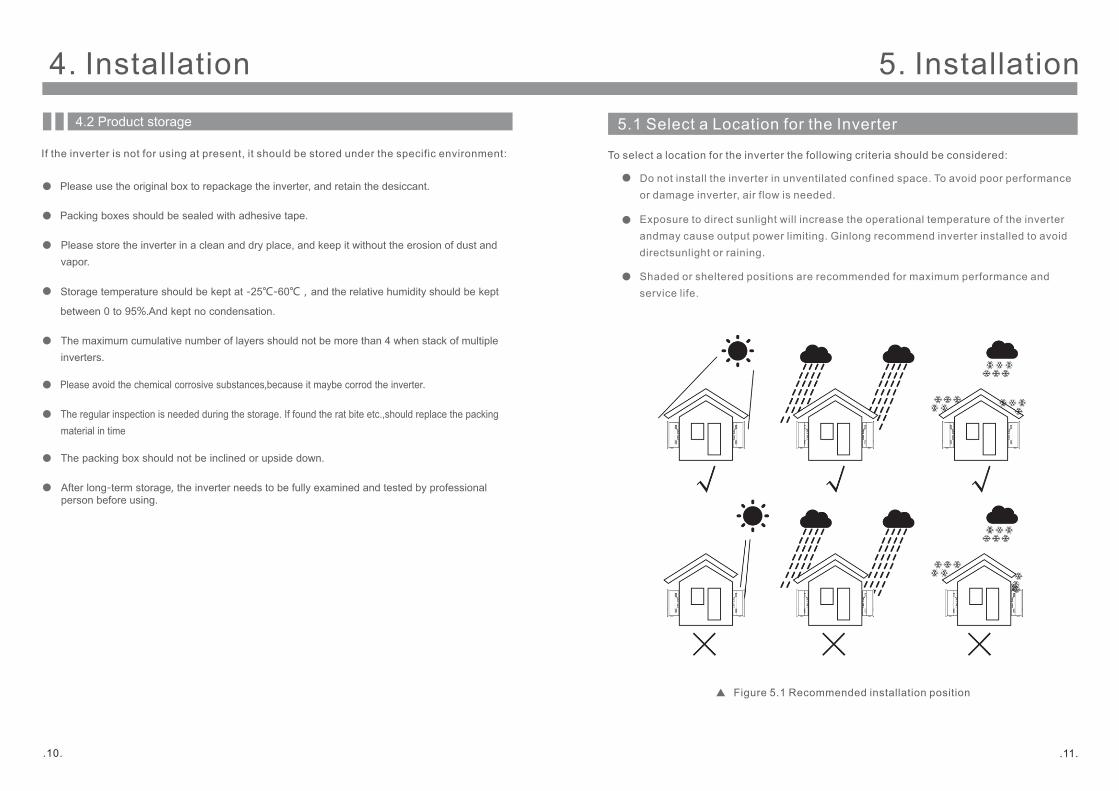
To select a location for the inverter the following criteria should be considered:
Do not install the inverter in unventilated confined space. To avoid poor performance
or damage inverter, air flow is needed.
Exposure to direct sunlight will increase the operational temperature of the inverter
andmay cause output power limiting. Ginlong recommend inverter installed to avoid
directsunlight or raining.
Shaded or sheltered positions are recommended for maximum performance and
service life.
Figure 5.1 Recommended installation position
4. Installation
4.2 Product storage
Please use the original box to repackage the inverter, and retain the desiccant.
Packing boxes should be sealed with adhesive tape.
Storage temperature should be kept at -25℃-60℃,and the relative humidity should be kept
between 0 to 95%.And kept no condensation.
Please avoid the chemical corrosive substances,because it maybe corrod the inverter.
The packing box should not be inclined or upside down.
After long-term storage, the inverter needs to be fully examined and tested by professional person before using.
If the inverter is not for using at present, it should be stored under the specific environment:
Please store the inverter in a clean and dry place, and keep it without the erosion of dust and
vapor.
5. Installation
The maximum cumulative number of layers should not be more than 4 when stack of multiple
inverters.
The regular inspection is needed during the storage. If found the rat bite etc.,should replace the packing
material in time
.11..10.
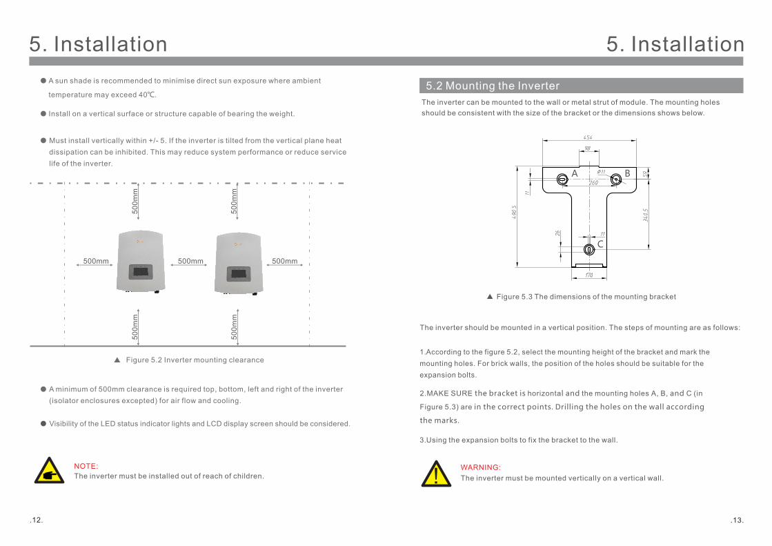
5.2 Mounting the Inverter
The inverter can be mounted to the wall or metal strut of module. The mounting holes
should be consistent with the size of the bracket or the dimensions shows below.
1. According to the figure 5.2, select the mounting height of the bracket and mark the
mounting holes. For brick walls, the position of the holes should be suitable for the
expansion bolts.
2.MAKE SURE the bracket is horizontal and the mounting holes A, B, and C (in
Figure 5.3) are in the correct points. Drilling the holes on the wall according
the marks.
WARNING:
The inverter must be mounted vertically on a vertical wall.
The inverter should be mounted in a vertical position. The steps of mounting are as follows:
Figure 5.3 The dimensions of the mounting bracket
3. Using the expansion bolts to fix the bracket to the wall.
Install on a vertical surface or structure capable of bearing the weight.
Must install vertically within +/- 5. If the inverter is tilted from the vertical plane heat
dissipation can be inhibited. This may reduce system performance or reduce service
life of the inverter.
Visibility of the LED status indicator lights and LCD display screen should be considered.
NOTE:
The inverter must be installed out of reach of children.
A minimum of 500mm clearance is required top, bottom, left and right of the inverter
(isolator enclosures excepted) for air flow and cooling.
500mm
50
0m
m
50
0m
m
500mm 500mm
50
0m
m
50
0m
m
Figure 5.2 Inverter mounting clearance
A B
C
5. Installation
A sun shade is recommended to minimise direct sun exposure where ambient
temperature may exceed 40℃.
5. Installation
.12. .13.
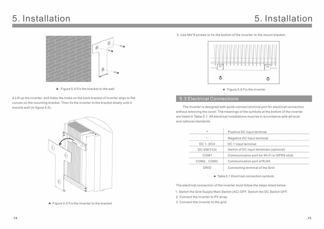
5. Use M4*9 screws to fix the bottom of the inverter to the mount bracket.
5.3 Electrical Connections
The electrical connection of the inverter must follow the steps listed below:
1. Switch the Grid Supply Main Switch (AC) OFF. Switch the DC Switch OFF.
2. Connect the inverter to PV array.
3. Connect the inverter to the grid.
The Inverter is designed with quick-connect terminal port for electrical connection
without removing the cover. The meanings of the symbols at the bottom of the inverter
are listed in Table 5.1. All electrical installations must be in accordance with all local
and national standards.
Table 5.1 Electrical connection symbols
GRID
COM1
Connecting terminal of the Grid
DC 1 input terminalDC 1- DC4
+
_
Positive DC input terminal
Negative DC input terminal
DC SWITCH Switch of DC input terminals (optional)
Communication port for Wi-Fi or GPRS stick
COM2、COM3 Communication port of RJ45
Figure 5.6 Fix the inverter
4. Lift up the inverter, and make the holes on the back bracket of inverter align to the
convex on the mounting bracket. Then fix the inverter to the bracket slowly until it
mounts well (in figure 5.5).
Figure 5.4 Fix the bracket to the wall
Figure 5.5 Fix the inverter to the bracket
5. Installation 5. Installation
.14. .15.

2) Prepare OT terminals: M4.
GinLong recommend 2 protection methods: AC terminal to connect ground and
external heat sink to connect ground .
If AC terminal is used to connect ground, please refer to the contents of 5.3.2.
If the heat sink is used to connect the ground, please
Follow the steps below:
5.3.1Protective ground wire connection(PE)
.16. .17.
1) Prepare the grounding cable: recommend to use the 16mm2 outdoor
copper-core cable.
For multiple inverters parallel system, all inverters should be connected
to each other to ensure the electric potential connections such as
grounding wire connecting.
3) using the wire stripper to strip the grounding cable insulation at the suitable length
(as shown as Figure 5.7)
B (insulation stripping length) is 2mm~3mm longer than A (OT cable
terminal crimping area) 2mm~3mm.
4) Infix the stripped wire into the OT terminal crimping area, and use the hydraulic
clamp to press (as shown as Figure 5.8).
Figure5.7 suitable length
Figure5.8 strip wire
Terminal conductor cavity formed after pressing and coat the cable,and the
cable conductors and terminals are connnected closely.
5) Screw down the screws at the ground position.
6) Use the screws of the ground position to fix grounding cable, and use T20 flower
type screwdriver to fasten the screw, fastening torque is 2Nm (as shown as Figure 5.9).
In order to improve the corrosion resistance of the grounding terminal, we
recommend that the External grounding terminal should be coated with
silica gel or paint for protection after completing the installation of the
grounding cable.
Important:
Important:
Important:
Figure5.9 fix the cable
Important:
A
B
D
C
5. Installation 5. Installation

iv) Insert the contact pin to the top part of the connector and screw up the cap nut to
the top part of the connector,Torque using 2.5-3Nm (as shown in Figure 5.15).
iii) Crimp the contact pin to the wire using a proper wire crimper as shown in Figure 5.14.
Figure 5.15 Connector with Cap nut Screwed on
Figure 5.14 Crimp the contact pin to the wire
v) Then connect the DC connectors to the inverter. Small click will confirm connection (as shown
in Figure 5.16).
Figure 5.16 Connect the DC Connectors to the Inverter
Figure 5.10 DC+ Connector Figure 5.11 DC- Connector
�B) Connect the “DC+”and “DC-”to the input terminals; see Figure 5.10 and Figure 5.11.
A) Please make sure the polarity of the output voltage of PV array matches the
“DC+”and “DC-”symbols.
5.3.1 DC side connection
The steps of assembling the DC connectors are listed as follows:
I) Strip off the DC wire for about 7mm, Disassemble the connector cap nut
(see Figure 5.12).
ii) Insert the wire into the connector cap nut and contact pin as shown in Figure 4.12.
Figure 5.12 Disassemble the Connector Cap nut
Figure 5.13 Insert the Wire into the Connector Cap nut and contact pin
5. Installation 5. Installation
.18. .19.
Cable typeOutside diameter of
cable(mm)
4.0~6.05.5~9.0
Traverse area(mm²)
Range
Industry generic PV cable
(model:PV1-F)
Recommended value
4.0(12AWG)(12~10AWG)
A) Strip the end of AC cable outer insulating jacket about 90mm then strip the end of each
wire about 15mm. (as shown in figure 5.17)
Figure 5.17 Strip AC cable
The steps to assemble the AC grid terminals are listed as follows:
Additional explanation:
If the diameter of the protective layer of the AC cable is less than the recommended
(20K models: 17-25mm;30K models: 21-30mm) it should be spirally wounded the
protective.
The adhesive tape is provided in the accessories.
Winding AC cable in a spiral form.
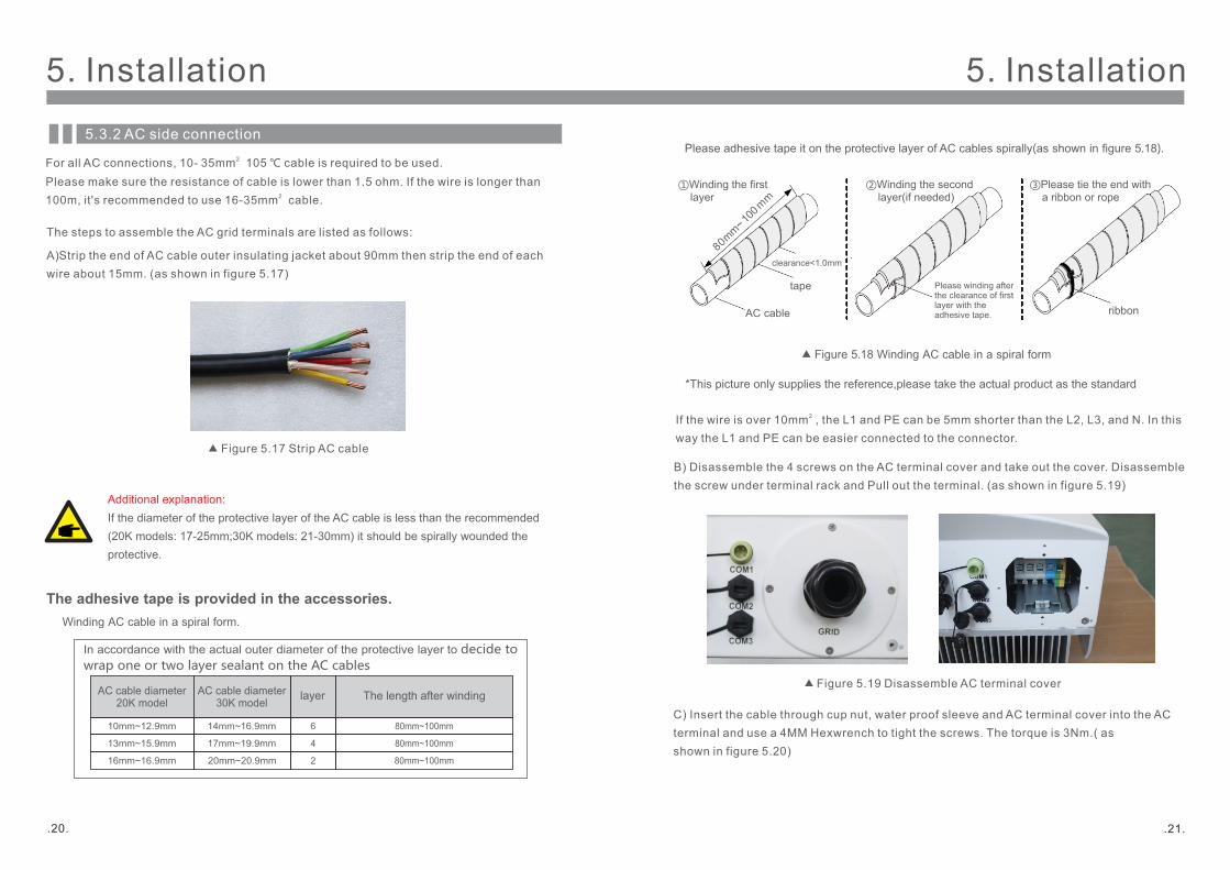
Please adhesive tape it on the protective layer of AC cables spirally(as shown in gure 5.18).
Figure 5.18 Winding AC cable in a spiral form
80mm
~10
0m
m
AC cable
tape
clearance<1.0mm
Please winding after the clearance of rst layer with the adhesive tape. ribbon
In accordance with the actual outer diameter of the protective layer to decide to
wrap one or two layer sealant on the AC cables
layer
14mm~16.9mm
17mm~19.9mm
6
4
80mm~100mm
80mm~100mm
20mm~20.9mm 2 80mm~100mm
10mm~12.9mm
13mm~15.9mm
16mm~16.9mm
For all AC connections, 10- 35mm 105 ℃ cable is required to be used. 2
Please make sure the resistance of cable is lower than 1.5 ohm. If the wire is longer than
100m, it's recommended to use 16-35mm cable.2
5.3.2 AC side connection
The length after windingAC cable diameter30K model
AC cable diameter20K model
①Winding the rst layer
②Winding the second layer(if needed)
③Please tie the end with a ribbon or rope
*This picture only supplies the reference,please take the actual product as the standard
B) Disassemble the 4 screws on the AC terminal cover and take out the cover. Disassemble
the screw under terminal rack and Pull out the terminal. (as shown in figure 5.19)
C) Insert the cable through cup nut, water proof sleeve and AC terminal cover into the AC
terminal and use a 4MM Hexwrench to tight the screws. The torque is 3Nm.( as
shown in figure 5.20)
Figure 5.19 Disassemble AC terminal cover
If the wire is over 10mm , the L1 and PE can be 5mm shorter than the L2, L3, and N. In this 2
way the L1 and PE can be easier connected to the connector.
5. Installation 5. Installation
.20. .21.
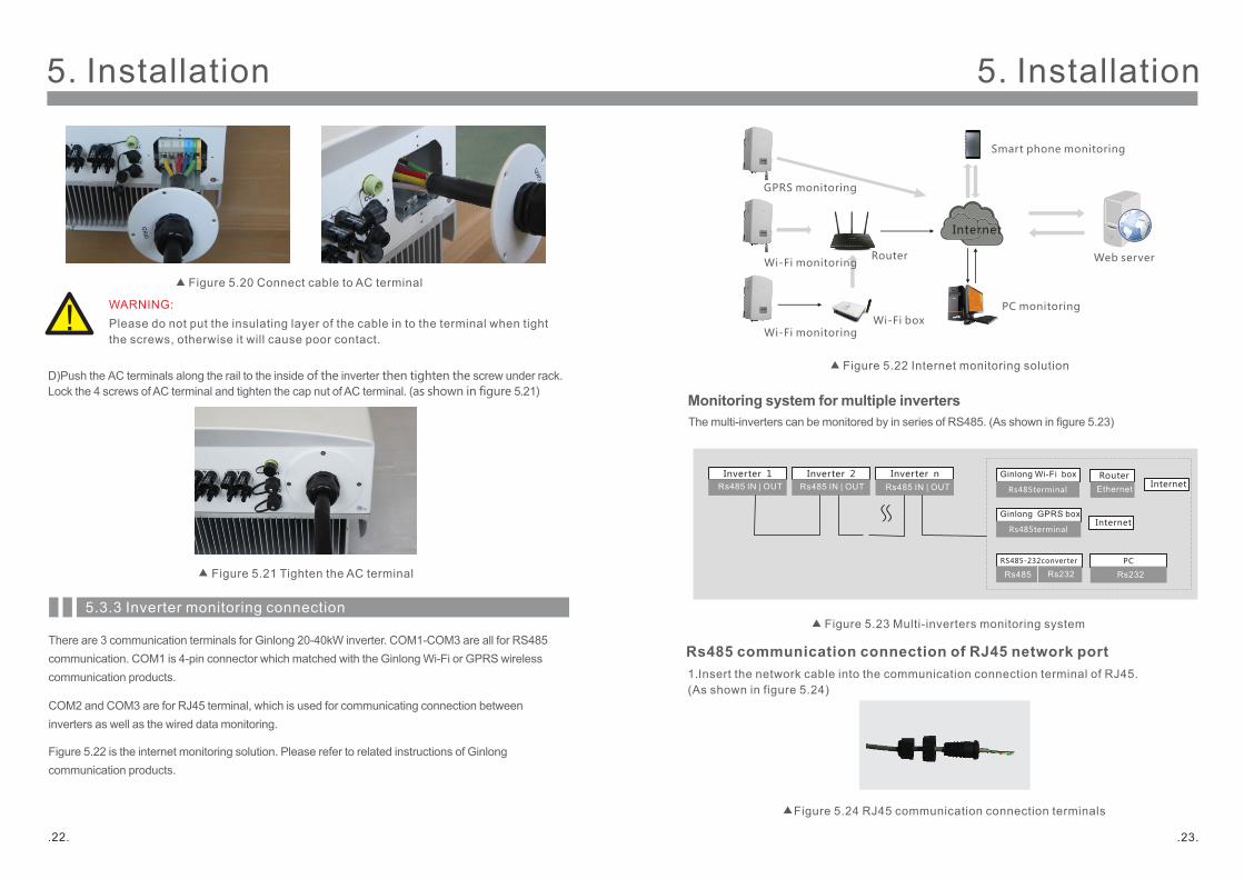
WARNING:
Please do not put the insulating layer of the cable in to the terminal when tight
the screws, otherwise it will cause poor contact.
D) Push the AC terminals along the rail to the inside of the inverter then tighten the screw under rack.
Lock the 4 screws of AC terminal and tighten the cap nut of AC terminal. (as shown in figure 5.21)
5.3.3 Inverter monitoring connection
There are 3 communication terminals for Ginlong 20-40kW inverter. COM1-COM3 are all for RS485
communication. COM1 is 4-pin connector which matched with the Ginlong Wi-Fi or GPRS wireless
communication products.
COM2 and COM3 are for RJ45 terminal, which is used for communicating connection between
inverters as well as the wired data monitoring.
Figure 5.22 is the internet monitoring solution. Please refer to related instructions of Ginlong
communication products.
Figure 5.20 Connect cable to AC terminal
Figure 5.21 Tighten the AC terminal
Rs485 communication connection of RJ45 network port
1. Insert the network cable into the communication connection terminal of RJ45.
(As shown in figure 5.24)
Figure 5.24 RJ45 communication connection terminals
Internet
GPRS monitoring
Wi-Fi monitoring
Smart phone monitoring
PC monitoring
Web serverRouter
Wi-Fi monitoring Wi-Fi box
Monitoring system for multiple inverters
The multi-inverters can be monitored by in series of RS485. (As shown in figure 5.23)
多台逆变器与电脑或数据采集器通讯时时,必须通过液晶设置通讯参数。
≈
Inverter 1 Inverter 2 Inverter n
Rs485 IN | OUT Rs485 IN | OUT Rs485 IN | OUT Rs485terminal
Rs485 Rs232 Rs232
Ethernet
Ginlong Wi-Fi box
RS485-232converter PC
Router
Rs485terminal
Ginlong GPRS box
Internet
Internet
Figure 5.22 Internet monitoring solution
Figure 5.23 Multi-inverters monitoring system
5. Installation 5. Installation
.22. .23.
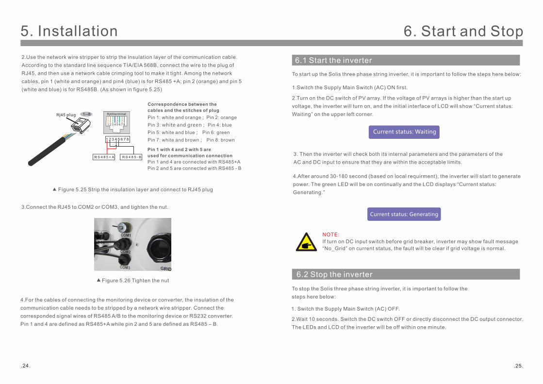
2. Use the network wire stripper to strip the insulation layer of the communication cable.
According to the standard line sequence TIA/EIA 568B, connect the wire to the plug of
RJ45, and then use a network cable crimping tool to make it tight. Among the network
cables, pin 1 (white and orange) and pin4 (blue) is for RS485 +A; pin 2 (orange) and pin 5
(white and blue) is for RS485B. (As shown in figure 5.25)
3. Connect the RJ45 to COM2 or COM3, and tighten the nut.
Figure 5.25 Strip the insulation layer and connect to RJ45 plug
Figure 5.26 Tighten the nut
Correspondence between the
cables and the stitches of plug
Pin 1: white and orange ; Pin 2: orange
Pin 3: white and green; Pin 4: blue
Pin 5: white and blue; Pin 6: green
Pin 7: white and brown; Pin 8: brown
Pin 1 with 4 and 2 with 5 are
used for communication connection
Pin 1 and 4 are connected with RS485+A
Pin 2 and 5 are connected with RS485 - B
1--8Rj45 plug Rj45terminal
1 2 3 4 5 6 7 8
1 2 3 4 5 6 7 8
R S 4 8 5 + A R S 4 8 5 - B
4. For the cables of connecting the monitoring device or converter, the insulation of the
communication cable needs to be stripped by a network wire stripper. Connect the
corresponded signal wires of RS485 A/B to the monitoring device or RS232 converter.
Pin 1 and 4 are defined as RS485+A while pin 2 and 5 are defined as RS485 – B.
6.2 Stop the inverter
To stop the Solis three phase string inverter, it is important to follow the
steps here below:
1. Switch the Supply Main Switch (AC) OFF.
2. Wait 10 seconds. Switch the DC switch OFF or directly disconnect the DC output connector.
The LEDs and LCD of the inverter will be off within one minute.
6.1 Start the inverter
To start up the Solis three phase string inverter, it is important to follow the steps here below:
1. Switch the Supply Main Switch (AC) ON first.
2. Turn on the DC switch of PV array. If the voltage of PV arrays is higher than the start up
voltage, the inverter will turn on, and the initial interface of LCD will show “Current status:
Waiting” on the upper left corner.
3. Then the inverter will check both its internal parameters and the parameters of the
AC and DC input to ensure that they are within the acceptable limits.
4. After around 30-180 second (based on local requirment), the inverter will start to generate
power. The green LED will be on continually and the LCD displays “Current status:
Generating.”
Current status: Waiting
Current status: Generating
NOTE:
If turn on DC input switch before grid breaker, inverter may show fault message
“No_Grid” on current status, the fault will be clear if grid voltage is normal.
6. Start and Stop5. Installation
.24. .25.
7. General Operation
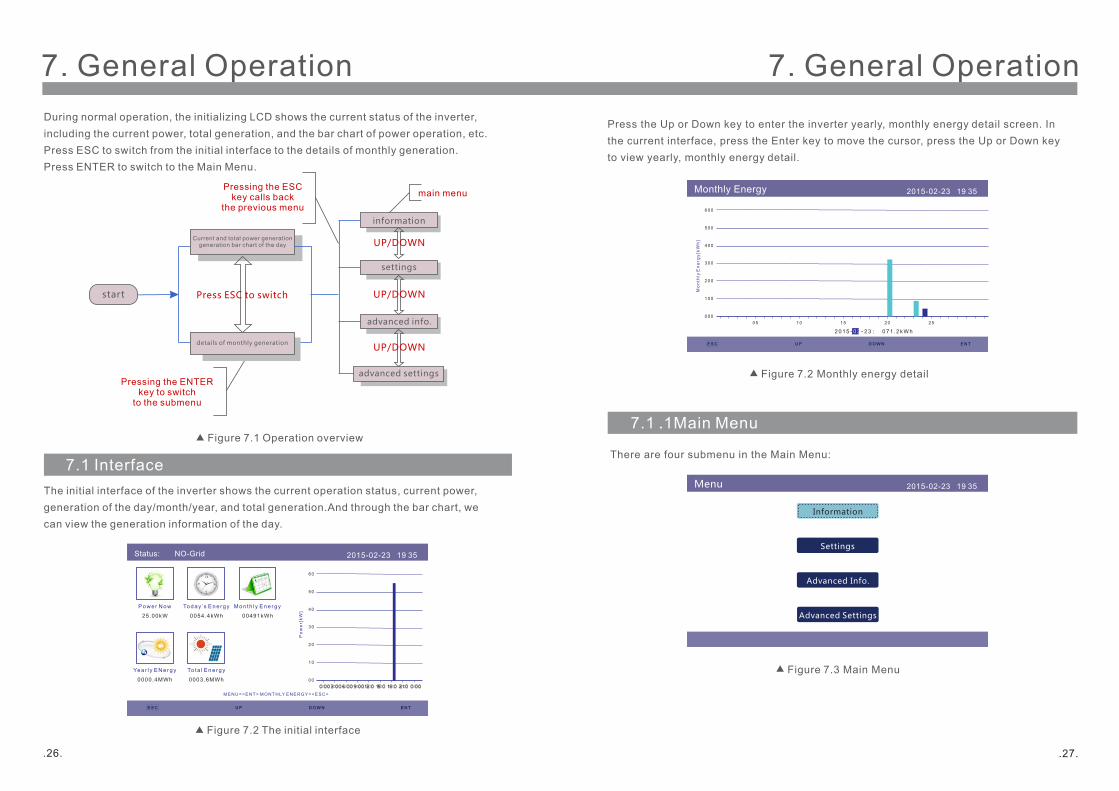
During normal operation, the initializing LCD shows the current status of the inverter,
including the current power, total generation, and the bar chart of power operation, etc.
Press ESC to switch from the initial interface to the details of monthly generation.
Press ENTER to switch to the Main Menu.
start
Current and total power generationgeneration bar chart of the day
details of monthly generation
information
settings
advanced info.
advanced settings
UP/DOWN
UP/DOWN
UP/DOWN
Press ESC to switch
Pressing the ENTER key to switch
to the submenu
Pressing the ESC key calls back
the previous menu
main menu
Figure 7.1 Operation overview
7.1 Interface
The initial interface of the inverter shows the current operation status, current power,
generation of the day/month/year, and total generation.And through the bar chart, we
can view the generation information of the day.
Figure 7.2 The initial interface
Pow e r No w To da y ’s Ene rgy Mo n th l y Ene rg y
25.00kW 0054.4kWh 00491kWh
Ye a r l y EN e rgy
0000.4MWh
To ta l Ene rg y
0003.6MWh
Status: NO-Grid 2015-02-23 19 35
M EN U =<EN T> MON TH LY EN ER GY=<ESC >
ESC U P D OWN EN T
0:003:006:009:0012:0 15:0 18:0 21:0 0:00
0 0
1 0
2 0
3 0
4 0
5 0
6 0
Po
we
r[k
W]
7. General Operation
7.1 .1Main Menu
There are four submenu in the Main Menu:
Press the Up or Down key to enter the inverter yearly, monthly energy detail screen. In
the current interface, press the Enter key to move the cursor, press the Up or Down key
to view yearly, monthly energy detail.
Figure 7.2 Monthly energy detail
Monthly Energy 2015-02-23 19 35
2 01 5 - - 2 3 : 0 71 .2 kWh0 2
0 0 0
1 0 0
2 0 0
3 0 0
4 0 0
5 0 0
6 0 0
Mo
nth
ly E
ne
rgy
[kW
h]
0 5 1 0 1 5 2 0 2 5
E S C U P D OWN E N T
Figure 7.3 Main Menu
Menu 2015-02-23 19 35
Information
Settings
Advanced Info.
Advanced Settings
.26. .27.
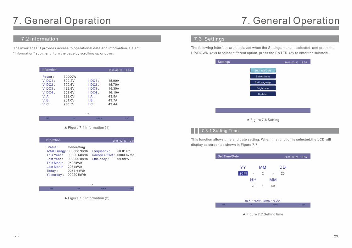
7.2 Information
The inverter LCD provides access to operational data and information. Select
"Information" sub menu, turn the page by scrolling up or down.
Figure 7.4 Information (1)
Figure 7.5 Information (2)
Informtion 2015-02-23 19 35
1 /2
Power:
V_DC1:
V_DC2:
V_DC3:
V_DC4:
V_A:
V_B:
V_C:
I_DC1:
I_DC2:
I_DC3:
I_DC4:
I_A:
I_B:
I_C:
30000W
500.2V
500.5V
499.9V
502.6V
232.0V
231.0V
230.5V
15.90A
15.70A
15.30A
16.10A
43.5A
43.7A
43.4A
ESC U P D OWN EN T
Informtion 2015-02-23 19 35
2 /2
Status:
Total Energy:
This Year:
Last Year:
This Month:
Last Month:
Today:
Yesterday:
Frequency:
Carbon Offset:
Efciency:
Generating
0003687kWh
0000014kWh
0000001kWh
0508kWh
2081kWh
0071.6kWh
000204kWh
50.01Hz
0003.67ton
99.99%
ESC U P D OWN EN T
7. General Operation7. General Operation
7.3 Settings
The following interface are displayed when the Settings menu is selected, and press the
UP/DOWN keys to select different option, press the ENTER key to enter the submenu.
7.3.1 Setting Time
This function allows time and date setting. When this function is selected,the LCD will
display as screen as shown in Figure 7.7.
Figure 7.6 Setting
Figure 7.7 Setting time
Settings 2015-02-23 19 35
Set Time/Date
Set Address
Set Language
Brightness
Updater
Set Time/Date 2015-02-23 19 35
NEXT= <ENT> D ON E= <ESC >
MM DDYY
2 232015 --
HH MM
20 53:
E S C U P D OWN E N T
.28. .29.
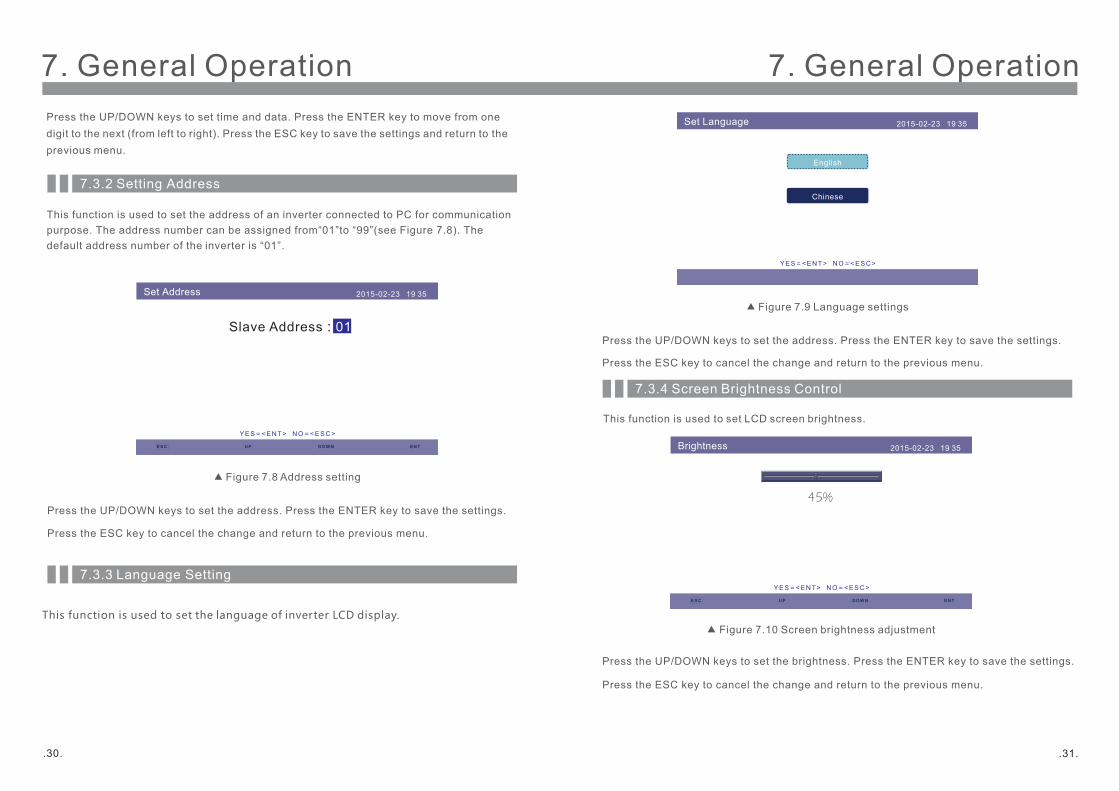
7.3.2 Setting Address
Press the UP/DOWN keys to set the address. Press the ENTER key to save the settings.
This function is used to set the address of an inverter connected to PC for communication
purpose. The address number can be assigned from“01”to “99”(see Figure 7.8). The
default address number of the inverter is “01”.
Figure 7.8 Address setting
7.3.3 Language Setting
This function is used to set the language of inverter LCD display.
Press the UP/DOWN keys to set time and data. Press the ENTER key to move from one
digit to the next (from left to right). Press the ESC key to save the settings and return to the
previous menu.
Set Address 2015-02-23 19 35
YES= <ENT> NO= <ESC>
Slave Address:01
ESC U P D OWN EN T
Press the ESC key to cancel the change and return to the previous menu.
7. General Operation 7. General Operation
7.3.4 Screen Brightness Control
This function is used to set LCD screen brightness.
Figure 7.9 Language settings
Figure 7.10 Screen brightness adjustment
Set Language 2015-02-23 19 35
English
Chinese
YES= <EN T> N O= <ESC >
Press the UP/DOWN keys to set the address. Press the ENTER key to save the settings.
Press the ESC key to cancel the change and return to the previous menu.
Press the UP/DOWN keys to set the brightness. Press the ENTER key to save the settings.
Press the ESC key to cancel the change and return to the previous menu.
Brightness 2015-02-23 19 35
45%
ESC U P D OWN EN T
YES= <EN T> NO= <ESC>
.30. .31.

7.4 Advanced Info - Technicians Only
NOTE:
Password required – restricted access – authorised technicians only
Un-authorised access may void the warranty.
Select Advanced Info from main menu, the LCD screen show the password is needed:
Figure 7.12Enter a password
7.3.5 System Update
This function is used to view the current system version.
Figure 7.11 System version
Updater 2015-02-23 19 35
The Current HMI Version:08
ESC EN T
CAN CE= <ESC> UPDATE SYSTEM= <EN T>
Password 2015-02-23 19 35
Please Input The Current Password
X X X X
ESC U P D OWN EN T
YES= <ENT> NO= <ESC>
7. General Operation 7. General Operation
The screen can be scrolled manually by pressing the UP/DOWN keys.
Pressing the ENTER key gives access to a submenu.
7.4.1 Alarm Message
The display shows the 10 latest alarm messages (see Figure 7.14).
Screens can be scrolled manually by pressing the UP/ DOWN keys.
Figure 7.14 Alarm message
The default password is "0010", press the DOWN key to move cursor, press the UP key to
change the figure for input password, after entering correct password, the LCD will show as
below:
Figure 7.13 Advanced information
Adcanced Info. 2015-02-23 19 35
Alarm Message
Running Message
Version
Communication Data
Daily Energy
Mothly Energy
Yearly Energy
Totally Energy
Daily Records
Alarm Message 2015-02-23 19 35
Message
NO-Grid
NO-Grid
NO-Grid
NO-Grid
NO-Grid
Date/Time Data
02-23 19:35
02-23 19:34
02-23 19:34
02-23 19:24
02-23 18:22
01/40
0000
0000
0000
0000
0000
ESC U P D OWN EN T
.32. .33.
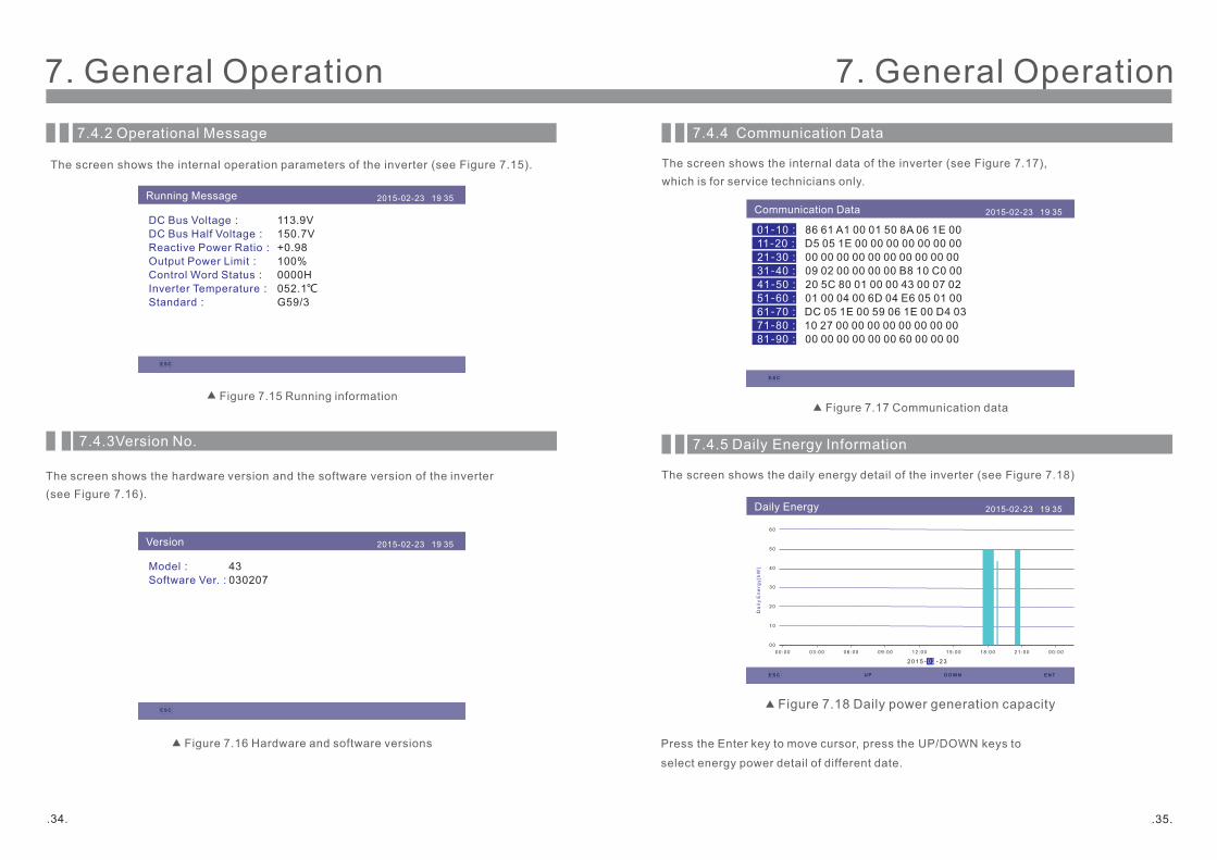
7.4.2 Operational Message
The screen shows the internal operation parameters of the inverter (see Figure 7.15).
7.4.3Version No.
The screen shows the hardware version and the software version of the inverter
(see Figure 7.16).
Figure 7.16 Hardware and software versions
版本号 2015-02-23 19 35
Figure 7.15 Running information
Running Message 2015-02-23 19 35
DC Bus Voltage:
DC Bus Half Voltage:
Reactive Power Ratio:
Output Power Limit:
Control Word Status:
Inverter Temperature:
Standard:
113.9V
150.7V
+0.98
100%
0000H
052.1℃
G59/3
ESC
Version 2015-02-23 19 35
Model:
Software Ver.:
43
030207
ESC
7. General Operation 7. General Operation
7.4.4 Communication Data
The screen shows the internal data of the inverter (see Figure 7.17),
which is for service technicians only.
Figure 7.17 Communication data
7.4.5 Daily Energy Information
The screen shows the daily energy detail of the inverter (see Figure 7.18)
Press the Enter key to move cursor, press the UP/DOWN keys to
select energy power detail of different date.
Figure 7.18 Daily power generation capacity
Communication Data 2015-02-23 19 35
01-10:
11-20:
21-30:
31-40:
41-50:
51-60:
61-70:
71-80:
81-90:
86 61 A1 00 01 50 8A 06 1E 00
D5 05 1E 00 00 00 00 00 00 00
00 00 00 00 00 00 00 00 00 00
09 02 00 00 00 00 B8 10 C0 00
20 5C 80 01 00 00 43 00 07 02
01 00 04 00 6D 04 E6 05 01 00
DC 05 1E 00 59 06 1E 00 D4 03
10 27 00 00 00 00 00 00 00 00
00 00 00 00 00 00 60 00 00 00
E S C
Daily Energy 2015-02-23 19 35
2 01 5 - - 2 30 2
0 0
1 0
2 0
3 0
4 0
5 0
6 0
Da
ily
En
erg
y[k
W]
0 0 : 0 0 0 3 :0 0 0 6 :0 0 0 9 :0 0 1 2 :0 0 1 5 :0 0 1 8 :0 0 2 1 :0 0 0 0 :0 0
E S C U P D OWN E N T
.34. .35.
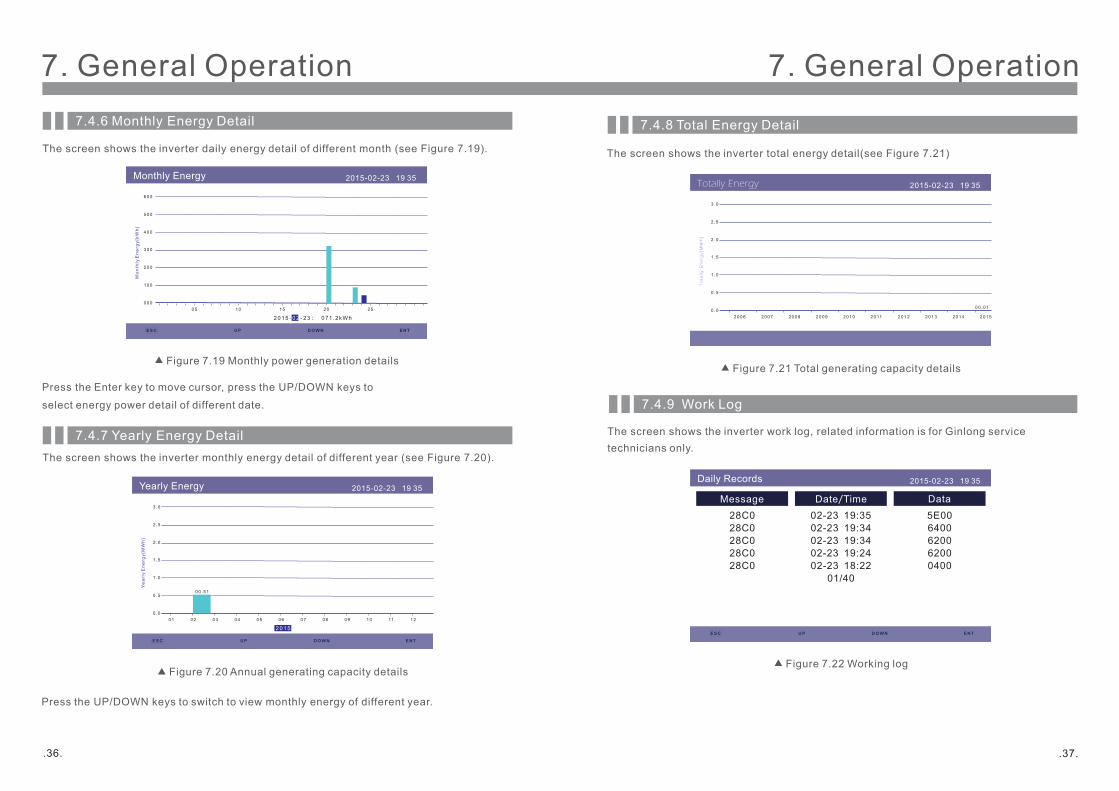
7.4.6 Monthly Energy Detail
The screen shows the inverter daily energy detail of different month (see Figure 7.19).
7.4.7 Yearly Energy Detail
Press the UP/DOWN keys to switch to view monthly energy of different year.
Figure 7.19 Monthly power generation details
Figure 7.20 Annual generating capacity details
The screen shows the inverter monthly energy detail of different year (see Figure 7.20).
Monthly Energy 2015-02-23 19 35
20 15 - - 23 : 07 1 .2kWh02
0 0 0
1 0 0
2 0 0
3 0 0
4 0 0
5 0 0
6 0 0
Mo
nth
ly E
ne
rgy
[kW
h]
0 5 1 0 1 5 2 0 2 5
ESC U P D OWN EN T
Press the Enter key to move cursor, press the UP/DOWN keys to
select energy power detail of different date.
Yearly Energy 2015-02-23 19 35
2 01 5
0 .0
0 .5
1 .0
1 .5
2 .0
2 .5
3 .0
Ye
arl
y E
ne
rgy
[MW
h]
0 1 0 2 0 3 0 4 0 5 0 6 0 7 0 8 0 9 1 0 11 1 2
0 0 .5 1
ESC U P D OWN EN T
7. General Operation7. General Operation
7.4.8 Total Energy Detail
The screen shows the inverter total energy detail(see Figure 7.21)
7.4.9 Work Log
The screen shows the inverter work log, related information is for Ginlong service
technicians only.
Figure 7.21 Total generating capacity details
Figure 7.22 Working log
Totally Energy 2015-02-23 19 35
0 .0
0 .5
1 .0
1 .5
2 .0
2 .5
3 .0
To
tall
y E
ne
rgy
[MW
h]
2 0 0 6 2 0 0 7 2 0 0 8 2 0 0 9 2 0 1 0 2 0 11 2 0 1 2 2 0 1 3 2 0 1 4 2 0 1 5
0 0 .0 1
Daily Records 2015-02-23 19 35
Message
28C0
28C0
28C0
28C0
28C0
Date/Time Data
02-23 19:35
02-23 19:34
02-23 19:34
02-23 19:24
02-23 18:22
01/40
5E00
6400
6200
6200
0400
ESC U P D OWN EN T
.36. .37.

Select grid standard (Figure 7.24)
7.5.1 Select Grid Standard
NOTE:
The "User-Def" function can be only used by the service engineer and changing
protection level must be allowed by the local grid company.
NOTE:
This is for service technicians only. The inverter is customized according to the
local standard before shipping, there should be no requirement to set the
standard.
7.5 Advanced Settings - Technicians Only
Select Advanced Settings from the Main Menu to access the following options:
NOTE:
This function is for authorised technicians only. Improper access and operation
may result in abnormal results and damage to the inverter.
Password required – restricted access – authorised technicians only
Un-authorised access may void the warranty.
Figure 7.23 Advanced settings
Advanced Set. 2015-02-23 19 35
Select Standard
Grid ON/OFF
Power Control
Clear Energy
Restore Settings
Calibrate
Reset Password
7. General Operation7. General Operation
Press the UP/DOWN keys to select the standard (AS4777,VDE4105,UL-1741, G59/3,
CQC and “User-Def” function).Press the ENTER key to confirm the setting. Press the
ESC key to cancel changes and returns to previous menu.
Selecting the User-Def submenu will access to the following submenu (see Figure 7.25):
Figure 7.24 Select national standards
Figure 7.25 User-Def
Select Standard 2015-02-23 19 35
Select Standard
G59/3
ESC U P D OWN EN T
YES= <EN T> N O= <ESC >
User-Def 2015-02-23 19 35
OV-G-V1:
OV-G-V2:
UN-G-V1:
UN-G-V2:
OV-G-F1:
OV-G-F2:
UN-G-F1:
UN-G-F2:
Startup-T:
440V
459V
330V
299V
51.0Hz
52.0Hz
48.0Hz
47.0Hz
060s
OV-G-V1-T:
OV-G-V2-T:
UN-G-V1-T:
UN-G-V2-T:
OV-G-F1-T:
OV-G-F2-T:
UN-G-F1-T:
UN-G-F2-T:
Restore-T:
1.0s
0.2s
1.0s
0.2s
1.0s
0.2s
1.0s
0.2s
060s
S ELEC T= <ENT> D ONE= <ESC >
.38. .39.
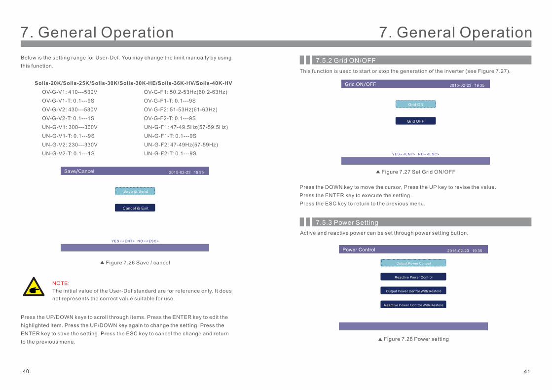
Below is the setting range for User-Def. You may change the limit manually by using
this function.
Solis-20K/Solis-25K/Solis-30K/Solis-30K-HE/Solis-36K-HV/Solis-40K-HV
OV-G-V1: 410---530V OV-G-F1: 50.2-53Hz(60.2-63Hz)
OV-G-V1-T: 0.1---9S OV-G-F1-T: 0.1---9S
OV-G-V2: 430---580V OV-G-F2: 51-53Hz(61-63Hz)
OV-G-V2-T: 0.1---1S OV-G-F2-T: 0.1---9S
UN-G-V1: 300---360V UN-G-F1: 47-49.5Hz(57-59.5Hz)
UN-G-V1-T: 0.1---9S UN-G-F1-T: 0.1---9S
UN-G-V2: 230---330V UN-G-F2: 47-49Hz(57-59Hz)
UN-G-V2-T: 0.1---1S UN-G-F2-T: 0.1---9S
Press the UP/DOWN keys to scroll through items. Press the ENTER key to edit the
highlighted item. Press the UP/DOWN key again to change the setting. Press the
ENTER key to save the setting. Press the ESC key to cancel the change and return
to the previous menu.
NOTE:
The initial value of the User-Def standard are for reference only. It does
not represents the correct value suitable for use.
Figure 7.26 Save / cancel
Save/Cancel 2015-02-23 19 35
Save & Send
Cancel & Exit
YES= <ENT> NO= <ESC>
7. General Operation7. General Operation
This function is used to start or stop the generation of the inverter (see Figure 7.27).
Press the DOWN key to move the cursor, Press the UP key to revise the value.
Press the ENTER key to execute the setting.
Press the ESC key to return to the previous menu.
Figure 7.27 Set Grid ON/OFF
7.5.2 Grid ON/OFF
7.5.3 Power Setting
Active and reactive power can be set through power setting button.
Figure 7.28 Power setting
Grid ON/OFF 2015-02-23 19 35
Grid ON
Grid OFF
YES= <EN T> N O= <ESC >
Power Control 2015-02-23 19 35
Output Power Control
Reactive Power Control
Output Power Cortrol With Restore
Reactive Power Control With Restore
.40. .41.
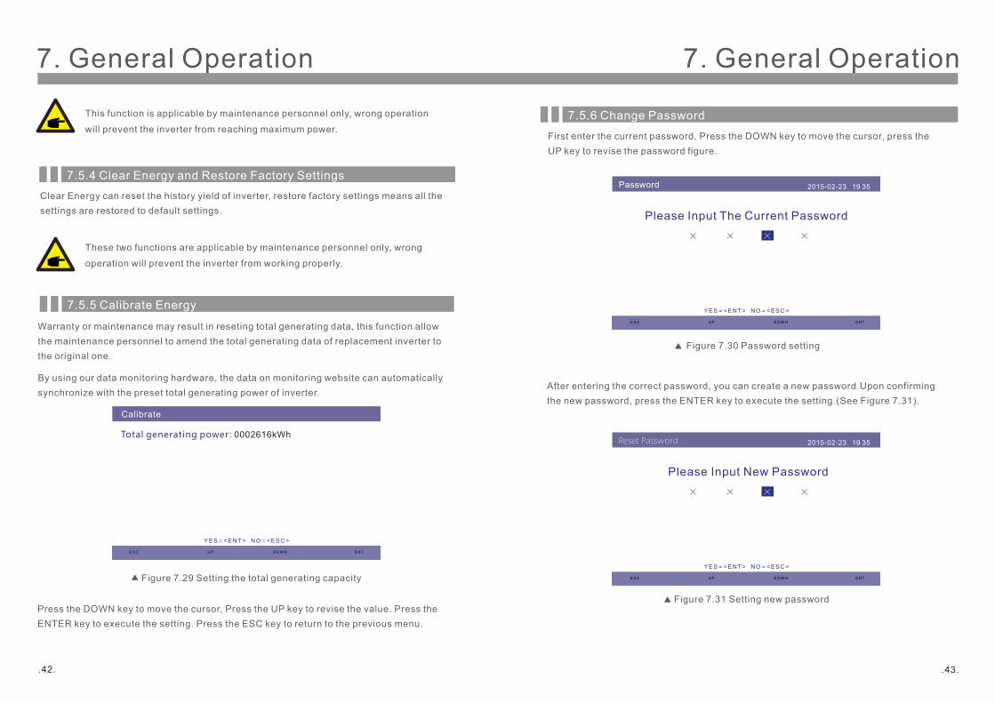
Figure 7.29 Setting the total generating capacity
Adjusting total generating power 2015-02-23 19 35Total generating power: 0002616kWh
7.5.5 Calibrate Energy
By using our data monitoring hardware, the data on monitoring website can automatically
synchronize with the preset total generating power of inverter.
Warranty or maintenance may result in reseting total generating data, this function allow
the maintenance personnel to amend the total generating data of replacement inverter to
the original one.
7.5.4 Clear Energy and Restore Factory Settings
Clear Energy can reset the history yield of inverter, restore factory settings means all the
settings are restored to default settings.
These two functions are applicable by maintenance personnel only, wrong
operation will prevent the inverter from working properly.
This function is applicable by maintenance personnel only, wrong operation
will prevent the inverter from reaching maximum power.
Press the DOWN key to move the cursor, Press the UP key to revise the value. Press the
ENTER key to execute the setting. Press the ESC key to return to the previous menu.
ESC U P D OWN EN T
YES= <ENT> N O= <ESC >
7. General Operation 7. General Operation
Calibrate
7.5.6 Change Password
First enter the current password, Press the DOWN key to move the cursor, press the
UP key to revise the password figure.
After entering the correct password, you can create a new password.Upon confirming
the new password, press the ENTER key to execute the setting.(See Figure 7.31).
Figure 7.30 Password setting
Figure 7.31 Setting new password
Password 2015-02-23 19 35
Please Input The Current Password
X X X X
ESC U P D OWN EN T
YES= <EN T> N O= <ESC >
Reset Password 2015-02-23 19 35
Please Input New Password
X X X X
ESC U P D OWN EN T
YES= <EN T> NO= <ESC >
.42. .43.
Note:
Never use any solvents, abrasives or corrosive materials to clean the inverter.
CAUTION:
Do not touch the surface when the inverter is operating. Some parts may be hot
and cause burns. Turn OFF the inverter (refer to Section 6.2) and let it cool down
before you do any maintenance or cleaning of inverter.
The LCD and the LED status indicator lights can be cleaned with cloth if they are too dirty
to be read.
The inverter has been designed in accordance with international grid tied standards for
safety, and electromagnetic compatibility requirements. Before delivering to the customer
the inverter has been subjected to several to ensure it’s optimal operation and reliability.
Solis three phase string inverter does not require any regular maintenance. However, clean the
heat-sink will help inverter dissipating heat and increase the life time of inverter.The dirt on the
inverter can be cleaned with a soft brush.
9. Trouble Shooting
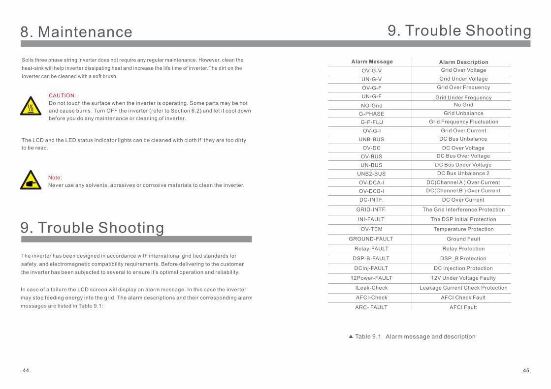
In case of a failure the LCD screen will display an alarm message. In this case the inverter
may stop feeding energy into the grid. The alarm descriptions and their corresponding alarm
messages are listed in Table 9.1:
8. Maintenance
Alarm Message
OV-G-V
UN-G-V
OV-G-F
UN-G-F
NO-Grid
G-PHASE
G-F-FLU
OV-G-I
UNB-BUS
OV-DC
OV-BUS
UN-BUS
UNB2-BUS
Alarm Description
Grid Over Voltage
Grid Under Voltage
Grid Over Frequency
Grid Under Frequency
No Grid
Grid Unbalance
Grid Frequency Fluctuation
Grid Over Current
DC Bus Unbalance
DC Over Voltage
DC Bus Over Voltage
DC Bus Under Voltage
DC Bus Unbalance 2
OV-DCA-I
OV-DCB-I
DC-INTF.
GRID-INTF.
INI-FAULT
OV-TEM
GROUND-FAULT
Relay-FAULT
DSP-B-FAULT
DCInj-FAULT
12Power-FAULT
ILeak-Check
AFCI-Check
ARC- FAULT
DC(Channel A ) Over Current
DC(Channel B ) Over Current
DC Over Current
The Grid Interference Protection
The DSP Initial Protection
Temperature Protection
Ground Fault
Relay Protection
DSP_B Protection
DC Injection Protection
12V Under Voltage Faulty
Leakage Current Check Protection
AFCI Check Fault
AFCI Fault
Table 9.1 Alarm message and description
9. Trouble Shooting
.44. . .45
9. Trouble Shooting
NOTE:
If the inverter displays any alarm message as listed in Table 9.1; please turn
off the inverter (refer to Section 6.2 to stop your inverter) and wait for 5 minutes
before restarting it (refer to Section 5.1 to start your inverter). If the failure
persists, please contact your local distributor or the service center. The below
that we will need so that we can assist you.
1. Serial number of the Inverter;
2. The distributor/dealer of the Inverter (if available);
3. Installation date.
4. The description of problem (i.e. the alarm message displayed on the LCD and the
status of the LED status indicator lights. Other readings obtained from the Information
submenu (refer to Section 7.2) will also be helpful.);
5. Your contact details.
10. Specification
.46. . .47
Operating Range Utility Frequency
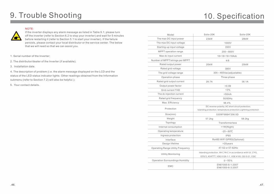
Model
The max DC input voltage
MPPT operation range
Max dc input current
Number of MPPT/strings per MPPT
Rated output power
Rated grid voltage
The grid voltage range
Operation phase
Rated grid output current
Output power factor
The dc injection current
Rated grid frequency
Max. Efficiency
Protection
Size(mm)
Weight
Topology
Internal consumption
Operating temperature
Ingress protection
Interface
Design lifetime
Utility Monitoring
Operation Surroundings Humidity
EMC
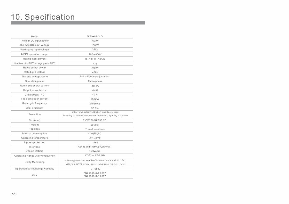
1000V
4/8
380V
304~460Vac(adjustable)
Three phase
>0.99
<50mA
50/60Hz
98.4%
Transformerless
-25~60℃
IP65
Rs485 WIFI GPRS(Optional)
>20years
47-52 or 57-62Hz
0~95%
EN61000-6-1:2007EN61000-6-3:2007
Solis-20K
200~800V
20kW
28.7A
57.2kg
<1W(Night)
DC reverse-polarity; AC short circuit protection;
Islanding protection; temperature protection;Lightning protection
Islanding protection, VA C FA C in accordance with UL 1741,
G59/3, AS4777, VDE 0126-1-1, VDE 4105, CEI 0-21, CQC
Grid current THD <3%
18+18+18+18Adc
The max DC input power 23kW
Starting-up input voltage 350V
530W*688H*356.5D
Solis-25K
25kW
36.1A
28kW
58.2kg
10. Specification10. Specification
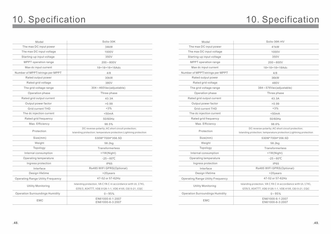
1000V
4/8
380V
304~460Vac(adjustable)
>0.99
<50mA
50/60Hz
98.5%
-25~60℃
IP65
0~95%
EN61000-6-1:2007EN61000-6-3:2007
Solis-30K
200~800V
30kW
43.3A
<3%
18+18+18+18Adc
34kW
350V
530W*700H*356.5D
58.2kg
Operating Range Utility Frequency
Model
The max DC input voltage
MPPT operation range
Max dc input current
Number of MPPT/strings per MPPT
Rated output power
Rated grid voltage
The grid voltage range
Operation phase
Rated grid output current
Output power factor
The dc injection current
Rated grid frequency
Max. Efficiency
Protection
Size(mm)
Weight
Topology
Internal consumption
Operating temperature
Ingress protection
Interface
Design lifetime
Utility Monitoring
Operation Surroundings Humidity
EMC
Grid current THD
The max DC input power
Starting-up input voltage
Three phase
Transformerless
Rs485 WIFI GPRS(Optional)
47-52 or 57-62Hz
<1W(Night)
DC reverse-polarity; AC short circuit protection;
Islanding protection; temperature protection;Lightning protection
Islanding protection, VA C FA C in accordance with UL 1741,
G59/3, AS4777, VDE 0126-1-1, VDE 4105, CEI 0-21, CQC
>20years
.48. . .49
Operating Range Utility Frequency
Model
The max DC input voltage
MPPT operation range
Max dc input current
Number of MPPT/strings per MPPT
Rated output power
Rated grid voltage
The grid voltage range
Operation phase
Rated grid output current
Output power factor
The dc injection current
Rated grid frequency
Max. Efficiency
Protection
Size(mm)
Weight
Topology
Internal consumption
Operating temperature
Ingress protection
Interface
Design lifetime
Utility Monitoring
Operation Surroundings Humidity
EMC
Grid current THD
The max DC input power
Starting-up input voltage
1000V
4/8
>0.99
<50mA
50/60Hz
98.6%
-25~60℃
IP65
0~95%
EN61000-6-1:2007EN61000-6-3:2007
200~800V
43.3A
<3%
Solis-36K-HV
36kW
18+18+18+18Adc
350V
41kW
530W*700H*356.5D
58.2kg
480V
384~576Vac(adjustable)
Three phase
Transformerless
Rs485 WIFI GPRS(Optional)
47-52 or 57-62Hz
<1W(Night)
DC reverse-polarity; AC short circuit protection;
Islanding protection; temperature protection;Lightning protection
Islanding protection, VA C FA C in accordance with UL 1741,
G59/3, AS4777, VDE 0126-1-1, VDE 4105, CEI 0-21, CQC
>20years
1000V
4/8
>0.99
<50mA
50/60Hz
98.6%
-25~60℃
IP65
0~95%
EN61000-6-1:2007EN61000-6-3:2007
200~800V
<3%
18+18+18+18Adc
350V
530W*700H*356.5D
58.2kg
480V
384~576Vac(adjustable)
Three phase
Transformerless
Rs485 WIFI GPRS(Optional)
47-52 or 57-62Hz
<1W(Night)
DC reverse-polarity; AC short circuit protection;
Islanding protection; temperature protection;Lightning protection
Islanding protection, VA C FA C in accordance with UL 1741,
G59/3, AS4777, VDE 0126-1-1, VDE 4105, CEI 0-21, CQC
>20years
Operating Range Utility Frequency
Model
The max DC input voltage
MPPT operation range
Max dc input current
Number of MPPT/strings per MPPT
Rated output power
Rated grid voltage
The grid voltage range
Operation phase
Rated grid output current
Output power factor
The dc injection current
Rated grid frequency
Max. Efficiency
Protection
Size(mm)
Weight
Topology
Internal consumption
Operating temperature
Ingress protection
Interface
Design lifetime
Utility Monitoring
Operation Surroundings Humidity
EMC
Grid current THD
The max DC input power
Starting-up input voltage
.50.
Solis-40K-HV
45kW
40kW
48.1A
10. Specification