single phase grid connected pv system - ethesisethesis.nitrkl.ac.in/7058/1/single_soren_2015.pdf ·...
TRANSCRIPT

1
SINGLE PHASE GRID CONNECTED PV SYSTEM A THESIS SUBMITTED IN PARTIAL FULFILLMENT OF THE REQUIREMENTS FOR
THE DEGREE OF
MASTER OF TECHNOLOGY (DUAL DEGREE) IN ELECTRICAL ENGINEERING
BY
SANJAY KUMAR SOREN
710EE3081
UNDER THE GUIDANCE OF
PROF. SOMNATH MAITY
Department of Electrical Engineering
National Institute of Technology, Rourkela
May 2014

2
SINGLE PHASE GRID CONNECTED PV SYSTEM A THESIS SUBMITTED IN PARTIAL FULFILLMENT OF THE REQUIREMENTS FOR
THE DEGREE OF
MASTER OF TECHNOLOGY (DUAL DEGREE) IN ELECTRICAL ENGINEERING
BY
SANJAY KUMAR SOREN
710EE3081
UNDER THE GUIDANCE OF
PROF. SOMNATH MAITY
Department of Electrical Engineering
National Institute of Technology, Rourkela
May 2014

3
Electrical Engineering Department
National Institute of Technology, Rourkela
CERTIFICATE
This is to certify that the thesis report entitled “SINGLE PHASE GRID CONNECTED PV
SYSTEM” submitted by Sanjay Kumar Soren, 710EE3081 in partial fulfillment of the requirement
for the degree of Masters of Degree (Dual Degree) in Electrical Engineering during 2014-2015 at
National Institute of Technology Rourkela is an authentic work by him under my supervision and
guidance.
Date Prof. Somnath Maity
Department of Electrical Engineering
National Institute of technology, Rourkela

4
Electrical Engineering Department
National Institute of Technology, Rourkela
ACKNOWLEDGEMENT
I would like to express my sincere thanks to my project supervisor Prof. Somnath Maity,
Department of Electrical Engineering, N.I.T. Rourkela, for his constant support, timely help,
guidance, sincere co-operation during the entire period of my work. I am grateful to him for
providing all the necessary facilities during the course of the project work.
Sanjay Kumar Soren
Electrical Engineering
NIT Rourkela
5
ABSTRACT
A single phase grid connected with a photovoltaic (PV) power system that will provide high
voltage gain with state model analysis for the control of the system has been presented. First the
photovoltaic system is designed and simulated using MATLAB SIMULINK software. The output
voltage of a PV array is comparatively low thus high voltage gain is necessary for grid-connection
and synchronization. The PV system has been provided with a boost converter which will boost
the low voltage of the PV array to high dc-voltage. A steady state model is obtained and is verified
with the help of simulation. A full bridge inverter with bidirectional power flow is used as the
second power processing stage, which stabilizes the dc voltage and the output current. Further, a
maximum-power-point-tracking method is employed in the PV system to obtain a high
performance.

6

7
Contents ABSTRACT ............................................................................................................................................... 5
INTRODUCTION ....................................................................................................................................... 8
LITERATURE REVIEW ............................................................................................................................ 9
MOTIVATION ..................................................................................................................................... 10
PHOTOVOLTAIC SYSTEM ........................................................................................................................ 11
WORKING PRINCIPLE ......................................................................................................................... 11
. ......................................................................................................................................................... 13
MAXIMUM POWER POINT TRACKING .................................................................................................... 14
METHODS FOR MPPT......................................................................................................................... 14
Perturb and Observe Method ........................................................................................................ 14
3.1.2. Incremental Conductance Method ....................................................................................... 14
3.1.3. Parasitic Capacitance Method .............................................................................................. 15
3.1.4. Constant Voltage Method .................................................................................................... 15
3.1.5. Constant Current Method .................................................................................................... 15
Flowchart of MPPT Algorithm ............................................................................................................ 16
BOOST CONVERTER ............................................................................................................................... 16
4.1. Modes of Operation .................................................................................................................... 17
4.1.1. Charging Mode ........................................................................................................................ 17
4.1.2. Discharging Mode .................................................................................................................... 18
INVERTER .............................................................................................................................................. 18
5.1. Operation of Inverter .................................................................................................................. 21
CONTROL STRATEGY OF FULL BRIDGE INVERTER ................................................................................... 24
Control of the Bidirectional Power Flow............................................................................................. 25
Direct Current Control with Compensation Unit................................................................................. 26
GRID SYNCHRONIZATION TECHNIQUE ................................................................................................... 27
SIMULATION RESULTS ........................................................................................................................... 31
8.1. SIMULINK MODEL OF PV PANEL .................................................................................................. 31
CONCLUSION ......................................................................................................................................... 38
9.1. FUTURE WORK ............................................................................................................................ 38
REFERENCES .......................................................................................................................................... 39

8
INTRODUCTION
Amongst the renewable source of energy, the photovoltaic power systems are gaining popularity,
with heavy demand in energy sector and to reduce environmental pollution around caused due to
excess use non-renewable source of energy. Several system structures are designed for grid
connected PV systems. Four different kinds of system configuration are used for grid connected
PV power application: the centralized inverter system, the string inverter system, the multi-string
inverter system and the module integrated inverter system.
The main advantages of using a grid connected PV systems are: effect on the environment is low,
the can be installed near to the consumer, thereby transmission lines losses can be saved, cost of
maintenance in the generating system can be reduced as there are no moving parts, system’s
modularity will allow the installed capacity to expand and carbon-dioxide gases are not emitted to
the environment.
For small distributed generator system , such as residential power utilization, all the above
mentioned types of inverters system other than centralized inverter system are be used. The main
problem in the design of the photovoltaic distributed generator system is to obtain high voltage
gain. For a typical photovoltaic model, the open circuit voltage is about 20 V and the maximum
power point (MPP) voltage is about 16 V whereas voltage of the utility grid is 220 V ac. Hence
high voltage amplification is mandatory for grid synchronization and to achieve low total harmonic
distortion (THD). In grid-connected PV system power electronics inverters are used for the power
conversion, interconnection and control optimization. The steady state analysis and control
strategy of the system play a vital role in the grid synchronization. The output of the inverter should
be properly sinusoidal for proper grid synchronization. Hence it is clear that inverter required for
PV system, high power factor, low THD, fast dynamic response on how the control strategy are
adopted for grid inverters.
Ensuring current injected into the grid with low harmonic content and maintain the pahse with the
main voltage, the controller must be able to track down maximum power point tracking (MPPT)
mechanism using perturb and observe (P&O) algorithm for the PV model which will cause all the
available array power to be utilized.

9
It is mandatory that the most of the solutions designed to attain the PV system tasks such as MPPT,
in inverter and Power factor correction are employed at two different stages.
LITERATURE REVIEW Various algorithms are carried out in the building of integrated photovoltaic system’s
performance reveal that an average losses of about 20%-25% in electricity production.
These are caused mainly due to mismatching losses, partial shadows, and variation in
current-voltage (I-V) characteristics, difference in inclination of solar surfaces, and
temperature effects. These losses can be minimized by means of suitable electronics
devices, a low cost high efficiency dc-dc boost converter with maximum power point
tracking (MPPT) functions. Analysis on architecture of grid connected PV system were
proposed.
PV inverter, which plays a very important role in the operation of the PV system, is used
to convert dc power obtained from the PV array into ac power which would be fed into the
grid. The output waveform of the inverter can be improved by reducing its respective
harmonic content, and hence the size of the filter used and the interference due to the
switching action of the inverter [5]. In recent years, multilevel inverters have become more
attractive for researchers and manufacturers due to their advantages over conventional
PWM inverters.
The maximum power point tracking (MPPT0 function plays a very important role as the
voltage can have a wide range from 15V-40V with variable power capacities for a single
PV panel[]. When the input voltage is of wide range, high efficiency is difficult to achive
in a single stage micro-inverter. Hence dual stage micro-inverter which combines a step
up dc-dc converter and dc-ac inverter is implemented to obtain high efficiency as high as
the conventional PV string type inverter[7].
The controller for the inverter contains inner current loop and external voltage loop. The
external voltage loop stabilizes the voltage of the dc link capacitor for the inverter and
provides the magnitude of the reference current for the inner loop, while the inner loop
controls the output current of the inverter to track reference current and meet the
requirement of the grid[9].

10
MOTIVATION
Fossil fuels used for electric power generation has created several problems on the environment
including global warming and greenhouse effect. This has led to an era in which the increasing
demand of power has to be met by Grid connected system that are based on renewable on sources
such as wind, solar and hydro power that are renewable in nature.
The DG systems are distributed near the user's facility. These systems are mainly small scale
generations having capacity less than 20MW. These Distributed Generation (DG) systems need to
be controlled properly in order to ensure sinusoidal current injection into the grid. However, they
have a poor controllability due to their intermittent characteristics. Grid connected inverter is the
key element to maintain voltage at the point of common coupling (PCC) constant and to ensure
power quality improvements. For safe and reliable operation of power system based on DG system,
usually power plant operators should satisfy the grid code requirements such as grid stability, fault
ride through, power quality improvement, grid synchronization and power control etc. The major
issue associated with DG system is their synchronization with utility voltage vector. The
information about the phase angle of utility voltage vector is accurately tracked in order to control
the flow of active and reactive power and to turn on and off power devices.

11
PHOTOVOLTAIC SYSTEM
A photovoltaic (PV) cell is a particular electrical gadget that can change over sun oriented vitality
into direct current by photovoltaic impact. It is coordinated piece of sun oriented vitality
framework and is an imperative wellspring of option wellspring of vitality. The PV cells are made
of silicon consolidated or doped with diverse components to influence the conduct of electrons or
openings. Diverse materials, for example, copper indium diselenide (CIS), cadmium telluride
(CdTe), and gallium arsenide (GaAs), are produced for utilization in PV cells. In a PV cell, these
bits of materials are put together. The gadget is developed in such a route, to the point that the
intersection can be presented to obvious light, IR, or UV. At the point when such radiation strikes
the P-N intersection, a voltage contrast is delivered between the P sort and N sort materials.
Terminals joined with the semiconductor layers permit current to be drawn from the gadget.
Metallic contacts are given to associate the heap to the cell. The cell is set under a glass spread
joined to it by glue for mechanical assurance. The proficiency of a sunlight based cell fluctuates
between 15%-19% and builds up an open circuit voltage of the request 0.65 V and a most extreme
current thickness between 35-40mA/cm2.
WORKING PRINCIPLE
Vitality change in sun powered cells works of two vital steps. First and foremost, assimilation of
light produces an electron gap pair. The electron and gap are then isolated by the structure of the
gadget electrons to the negative terminal and openings to the positive terminal—subsequently
creating electrical force.
A perfect sun oriented cell is spoken to by a present source associated in parallel with a correcting
diode, as indicated in the identical circuit of Figure 1. The relating I-V trademark is portrayed by
the Shockley sun powered cell mathematical statement
퐼 = 퐼 + 퐼 + 퐼 (1)
퐼 = 퐼 푒( )
− 1 (2)

12
퐼 = 퐼 − 퐼 푒( )
− 1 − (3)
Fig-1. Equivalent circuit of a solar cell
VO: voltage appearing across diode.
V: load voltage.
I: Cell Current (A)
RS: internal (series) resistance of the system.
IO: Reverse saturation current of the diode.
T: Temperature in kelvin.
K: Boltzmann constant (1.38 x 10⁻²³ J / K).
n = Ideality factor (≈1.92).
q: electronic charge (1.6 x 10⁻¹⁹C).

13
.
The output of the solar cell i.e. the P-V and I-V curve is given in the following figure.
Fig-2. P-V Characteristics
Fig-3. I-V Characteristics

14
MAXIMUM POWER POINT TRACKING The efficiency of a solar cell is low. With a specific end goal to expand the efficiency, routines
are to be undertaken to match the source and load appropriately. One such strategy is the
Maximum Power Point Tracking (MPPT). This procedure is utilized to acquire the most
extreme conceivable force from a fluctuating source. In photovoltaic frameworks the I-V bend
is non-direct, along these lines making it hard to be utilized to power a certain heap. This is
finished by using a help converter whose duty cycle is differed by utilizing a mppt algorithm.
METHODS FOR MPPT There are different methods to track down the maximum power point, a few of which are listed below:
Perturb and Observe method
Incremental Conductance method
Parasitic Capacitance method
Constant Voltage method
Constant Current method
Perturb and Observe Method Perturb and Observe is the most regularly utilized MPPT strategy because of its simplicity of
execution. The working voltage is expanded the length of (dP )/dV is sure, i.e. the voltage is
expanded the length of we get more power. On the off chance that (dP )/dV is detected
negative, the working voltage is diminished. The voltage is kept put if (dP )/dV is close to zero
inside of a preset band. The time multifaceted nature of this calculation is less however on
coming to near to the MPP it doesn't stop at the MPP and continues annoying. This calculation
is not suitable when the variety in the sun oriented illumination is high. The voltage never
really achieves a careful esteem yet annoys around the most extreme force point (MPP).
3.1.2. Incremental Conductance Method
In this strategy the PV exhibit's incremental conductance dI/dV to figure the indication of
dP/dV. At the point when dI/dV is equivalent and inverse to the estimation of dP/dV (where
15
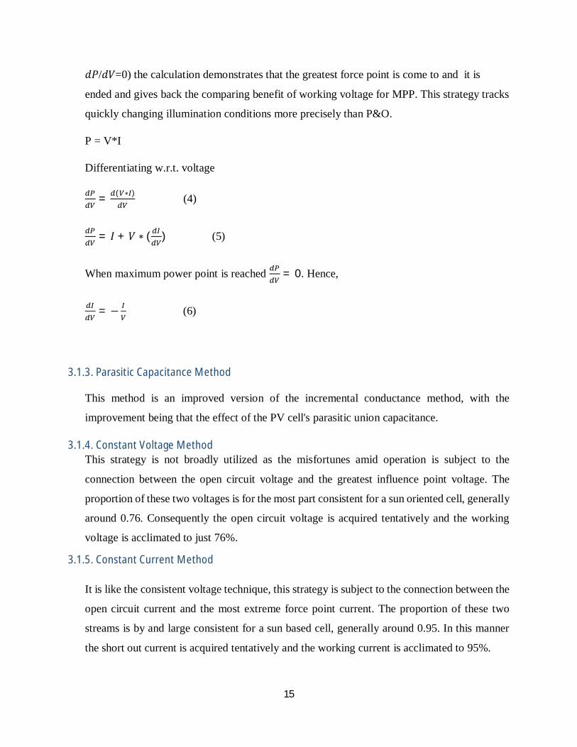
푑푃/푑푉=0) the calculation demonstrates that the greatest force point is come to and it is
ended and gives back the comparing benefit of working voltage for MPP. This strategy tracks
quickly changing illumination conditions more precisely than P&O.
P = V*I
Differentiating w.r.t. voltage
= ( ∗ ) (4)
= 퐼 + 푉 ∗ ( ) (5)
When maximum power point is reached = 0. Hence,
= − (6)
3.1.3. Parasitic Capacitance Method
This method is an improved version of the incremental conductance method, with the
improvement being that the effect of the PV cell's parasitic union capacitance.
3.1.4. Constant Voltage Method This strategy is not broadly utilized as the misfortunes amid operation is subject to the
connection between the open circuit voltage and the greatest influence point voltage. The
proportion of these two voltages is for the most part consistent for a sun oriented cell, generally
around 0.76. Consequently the open circuit voltage is acquired tentatively and the working
voltage is acclimated to just 76%.
3.1.5. Constant Current Method It is like the consistent voltage technique, this strategy is subject to the connection between the
open circuit current and the most extreme force point current. The proportion of these two
streams is by and large consistent for a sun based cell, generally around 0.95. In this manner
the short out current is acquired tentatively and the working current is acclimated to 95%.

16
Flowchart of MPPT Algorithm Perturb and Observe
Fig-4. Flowchart of Perturb and Observe
BOOST CONVERTER As the output of the PV panel is very low and in order to connect it to the grid, its voltage
has to be increased. The output of the solar panel is a DC voltage of very low magnitude.
Hence a boost converter is required for boosting the voltage to higher level without use of

17
the transformer. The primary parts of a support converter are an inductor, a diode and a
high recurrence switch. These in a composed way supply energy to the heap at a voltage
more prominent than the information voltage extent. One capacitor is joined over the
heap end to keep up the heap voltage consistent.
Fig-5. A boost Converter
4.1. Modes of Operation
Two methods of operation are there in a help converter. These are in light of the end and
opening of the switch. In the first mode the switch is shut; this is known as the charging
method of operation. The second mode is the point at which the switch is open; this is
known as the releasing method of operation. The circuit chart of a support converter is
given in fig-5.
4.1.1. Charging Mode The switch is shut and the inductor is charged by the source through the switch. The
charging current is exponential in nature and for straightforwardness it is thought to be
straightly fluctuating. The diode limits the stream of current from the source to the heap
and the interest of the heap is met by the releasing of the capacitor.

18
4.1.2. Discharging Mode
In the releasing method of operation the switch is open and the diode is forward one-sided
.The inductor now releases and together with the source charges the capacitor and takes
care of the heap requests. The heap current variety is little and by and large is expected
consistent all through the operation.
INVERTER Single stage inverters can be both of either square-wave or PWM inverters. The square wave
sort is the least complex system to create AC from DC; be that as it may, it experiences low
recurrence sounds which causes trouble in sifting through the clamor to keep these music to

19
return back to the essential side of the transformer. The PWM inverter powers the sounds to
be up higher than the basic (line) recurrence; consequently the separating necessity of the
inverter is minimized.
There are numerous mixed bags of inverter plans. The most well-known topology is alluded
to as the H-span topology. Its fundamental setup is indicated in Figure-6. This topology can
be utilized with either the square wave, or heartbeat width balance (PWM) exchanging plans.
Fig-6. H-bridge Single Phase Inverter
The square-wave exchanging strategy for controlling the switches (marked S1 through S4)
with a specific end goal to accomplish a square wave AC yield signal. The AC yield is
accomplished by utilizing a control signal with a 50% obligation cycle wired to S1 and S4. An
altered duplicate of the same sign is additionally wired to S2 and S3. This exchanging plan
guarantees that S1 and S4 are dependably on when S2 and S3 are OFF. It makes a square wave
yield as indicated in fig-7. The upside of utilizing a H-span inverter is that just a solitary, basic
control sign is obliged to control four transistors. The drawback, nonetheless, is that the square

20
wave yield is a low quality AC signal that infuses numerous music into any heaps to which it
is fueling.
Fig-7. Square wave output of Inverter
PWM control signs can be utilized with the same H-span geology. The disservice of the PWM
exchanging plan is that it is more muddled than the square-wave exchanging plan. Different,
moderately complex control signs are expected to control the transistors of the PWM inverter.
The point of interest, nonetheless, of the PWM exchanging plan is that, it has the capacity
create more sinusoidal yield than the square wave sort. The yield of PWM inverter is
demonstrated in Fig-8.

21
Fig-8. Output of PWM inverter
A proportional – Integral (PI) current control plan is utilized to keep the yield current sinusoidal
and to have high element execution under quickly changing environmental conditions and to keep
up the force variable at close solidarity. Sinusoidal PWM is acquired by contrasting a high-
recurrence transporter with a low-recurrence sinusoidal, which is the regulating or reference signal.
The transporter has a steady period; consequently, the switches have consistent exchanging
recurrence. The exchanging moment is resolved from the intersection of the transporter and the
regulating signal.
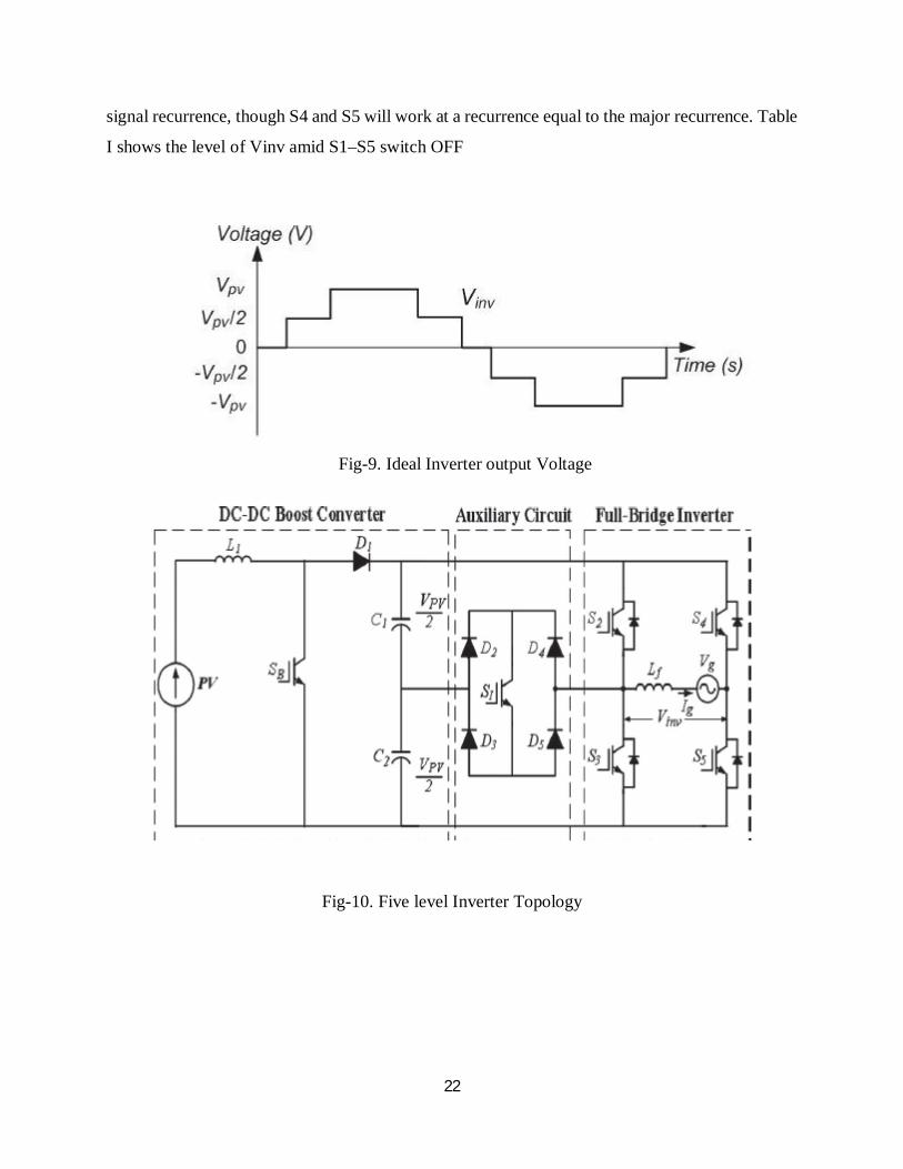
5.1. Operation of Inverter
The inverter produces five level yield voltage, i.e., 0, +Vpv/2, +Vpv, −Vpv/2, and –Vpv as in Fig.
9. As demonstrated in Fig. 10, an assistant circuit which comprises of four diodes and a switch S1
is utilized between the dc-transport capacitors and the full-connect inverter. Fitting exchanging
control of the assistant circuit can produce half level of PV supply voltage, i.e., +Vpv/2 and −Vpv/2
[6]. Two reference signals Vref1 and Vref2 will alternate to be contrasted and the transporter signal
at once. On the off chance that Vref1 surpasses the crest adequacy of the bearer signal Vcarrier,
Vref2 will be contrasted and the transporter sign till it achieves zero. At that point Vref1 assumes
control over the correlation process until it surpasses Vcarrier. This will prompt an exchanging
example, as demonstrated in Fig. 11. Switches S1–S3 will be exchanging at the rate of the bearer
22
signal recurrence, though S4 and S5 will work at a recurrence equal to the major recurrence. Table
I shows the level of Vinv amid S1–S5 switch OFF
Fig-9. Ideal Inverter output Voltage
Fig-10. Five level Inverter Topology

23
Fig-11. Switching Pattern of Five level single phase inverter

24
CONTROL STRATEGY OF FULL BRIDGE INVERTER Utilization of direct current-control system, the VS-PWM converter powers the prompt
burden current to precisely take after the sinusoidal reference, which synchronizes with the
utility matrix voltage and the powerful element, the low THD and the quick element
reaction are accomplished. Moreover, the bidirectional stream of force encourages the
remuneration of the dc-transport and the air conditioner side voltage variety which balances
out the dc-transport voltage.
TABLE-1. INVERTER OUTPUT VOLTAGE DURING SWTCHING
S1 S2 S3 S4 S5 Vinv
ON OFF OFF OFF ON +VPV/2
OFF ON OFF OFF ON +VPV
OFF OFF
Or
(ON)
OFF
Or
(ON)
ON
Or
(OFF)
ON
Or
(OFF)
0
ON OFF OFF ON OFF - VPV/2
OFF OFF ON ON OFF - VPV

25
Fig-12. Control Block of Full Bridge Inverter
Fig-12 shows the control block of the full bridge inverter with bidirectional power flow
Control of the Bidirectional Power Flow With reference to Fig-12, the dc-transport voltage Udc is controlled to keep Uref consistent
with zero lapse by the voltage-input control circle. The heading and extent of VS-PWM
converter's yield current and force are chosen by the estimation of Ue , which is the yield
of negative PI controller in the voltage circle.
On the off chance that Udc > Uref then Ue is expanding, and the VS-PWM converter fills
in as an inverter which exchanges the PV cluster energy to the utility network. The vitality
era of PV force framework is decidedly associated with the greatness of Ue .
26
On the off chance that Udc < Uref then Ue is diminishing, and when Ue < 0, the VS-PWM
converter functions as a PWM rectifier, which draws the vitality from the utility network
to the capacitor of dc transport, keeping up the steadiness of dc-transport voltage. The
present in the negative bearing at long last methodologies a little esteem, which is just
used to make up for the switch misfortunes of VS-PWM converter.
Direct Current Control with Compensation Unit
The load current iout is identified and contrasted and the reference current iref , and the
mistake sign is handled by a PI controller in the present input control circle. The upside of
the immediate current control are the low music diminishes misfortunes in relentless state,
the quick reaction to give high element exhibitions, and the top current insurance to reject
over-burden. For the most part, the present control circle is intended to have a transfer
speed of 2–5 kHz, higher than the voltage circle data transmission of 200–500 Hz, to
guarantee the solidness of the proposed inverter control with two PI controllers.
The quick power and the dc-transport voltage incorporate a swell part with the recurrence
2ω on account of a solitary stage inverter. Further the framework voltage is not a perfect
sinusoidal waveform by and by. Hence, it is difficult to accomplish low THD of the yield
current by utilizing the straightforward direct-current-control methodology in the genuine
matrix condition. Consequently two pay units are added to the present control circle as
food forward control units. The food forward control has little effect on the framework's
zeros and shafts setup, yet accomplishes to track the sinusoidal reference precisely and
limit the music mutilation of the peak current, particularly at the present.
Compensation coefficient Kd posses the magnitude of reference currents iref , and
counteract the main influences of the dc-bus voltage ripple because Kd represents
a negative fluctuating feature with the frequency 2ω, compared with the dc-bus voltage
ripple. Kd is defined as
퐾푑 = ( 7 )

27
The PI controller in the network voltage-bolster forward control duplicates the genuine,
damaged matrix voltage with an extent pick up Kf . Its yield Uc and the yield Ua of PI
controller in current input circle are as one nourished to the PWM modulator to deliver the
signs for the inverter switches. Hence, the balance wave Uout incorporates the flawed part
of lattice voltage to repay matrix voltage vacillation and get sinusoidal current waveform.
The food forward impact relies on upon the estimation of Kf .
GRID SYNCHRONIZATION TECHNIQUE

28
Synchronizations method can be divided into two categories: namely mathematical
analysis and PLL based methods. Among them, PLL method is gaining more attention.
A basic PLL consists of a phase detector (PD), a loop filter (LF) and a voltage controlled
oscillator (VCO) as shown in fig-13.
Fig-13. Structure of a PLL
휃 (푠)휃 (푠) =
퐾 퐾 퐺 (푠)푠 + 퐾 퐾 퐺 (푠)
= ()
Where, θ0, θi are output and input phases
K1,K2 are the gains of PD and VCO respectively.
Glf(s)= Kp + Ki/s is LF transfer function.
Kp,Ki are proportional and integral gains of LF.
The various kinds of PLL techniques are:
1. Linear PLL

29
Linear PLL (LPLL) is predominantly utilized for single stage voltage. It has a blender
which is utilized as a stage differentiator which gives a sign relative to the contrast
between the periods of the data and the yield signal. This mistake sign contains parts
at frequencies which are even products of the info recurrence. The circle channel
evacuates the consonant parts and just the corresponding segment is gone on to the
voltage controlled oscillator as per which the VCO yield is created.
Fig-14. Block diagram of LPLL
2. Synchronous Reference frame PLL A synchronous Reference Frame PLL (SRF PLL) is utilized for following the stage
point if there should arise an occurrence of 3-stage signals which meets expectations
in a comparable manner as a direct PLL with just distinction in the Phase Detector
(PD) piece. It uses Park's Transformation of a 3-stage motion as the PD. Figure 15
demonstrates the piece outline of a SRF PLL in which Va, Vb, Vc are the parts of a 3-
stage signal. To begin with square in the figure is Clarke's Transformation which
deciphers a 3-stage voltage vector from the abc common reference edge to the αβ
stationary reference outline. The second square is the Park's Transformation which
deciphers the αβ stationary reference edge to turning rotating frame.

30
Fig-15. Block Diagram of SRF PLL.

31
SIMULATION RESULTS
8.1. SIMULINK MODEL OF PV PANEL
Fig-8.1. PV Model
Fig-8.2. P-V Graph

32
Fig-8.3. I-V Graph
Fig-8.4. Subsystem Of PV Panel

33
Fig-8.5. Simulink Model of Grid Connected PV System
Fig-8.6.Simulink model of MPPT

34
Fig-8.7. Simulink model of Perturb & Observe
Fig-8.8. Simulink model of PID controller

35
Fig-8.8. H-Bridge Inverter
Fig-8.9. Simulink model of PLL

36
Fig-8.10. output of the inverter

37
Fig.8.11. Grid voltage output

38
CONCLUSION
A PWM generator was utilized for generating the pulse signal that was compared with the
signal generated from the MPPT unit to give out the gating signal to the switch.
If MPPT had not been used, then the user would have had to input the duty cycle to the
system. When there is change in the solar irradiation the maximum power point changes
and thus the required duty cycle for the operation of the model also changes. But if constant
duty cycle is used then maximum power point cannot be tracked and thus the system is less
efficient.
The various waveforms were obtained by using the plot mechanism in MATLAB. There
is a small loss of power from the solar panel side to the boost converter output side. This
can attributed to the switching losses and the losses in the inductor and capacitor of the
boost converter.
The parameters of the inverter model like the inductance, the dc gain (kv) and time constant
(tv) considerably affect the system dynamics at the switching time and should be chosen
properly to obtain a stable periodic behavior. When instead of PV, DC source is connected
the voltage waveform is quite similar to the reference voltage but both current and voltage
has some harmonic content in them. After connecting the PV module the harmonic content
in current and voltage increased and the output of the PV was also affected considerably.
A Linear PLL (LPLL) is used for synchronization for single phase signals with acceptable
results and a Synchronous Reference Frame (SRF) PLL is used for 3-phase balanced
signals. But it cannot be used for unbalanced utility conditions as the detected phase angle
contains 2nd harmonic oscillations.
9.1. FUTURE WORK Improvement to this project can be made by reducing the harmonics during
synchronization with the grid. Algorithm for SOGI PLL to be applied to obtain less
harmonic oscillation during steady state and transient conditions. Analyzing fast
algorithms to track the phase angle during abnormal grid conditions.

39
REFERENCES
[1] O. Wasynczuk, “Dynamic behavior of a class of photovoltaic power systems,” IEEE Transactions
on Power Apparatus and Systems, vol.PAS-102, no. 9, 1983, pp. 3031-3037.
[2] O. Wasynczuk, “Modeling and dynamic performance of a line commutated photovoltaic inverter
system, ” IEEE Transactions on Energy Conversion, vol. 4, no. 3, 1989, pp. 337-343.
[3] M. Chael, E. Ropp, and Sigifredo Gonzalez, “Development of a MATLAB/Simulink model of a
single phase grid connected photovoltaic system,” IEEE Transaction on Energy Conversion, vol 3,
pp. 344-349, 2009.
[4] Katsuma Ono, Toshimichi Saito, “Optimization of Switching Rule in DC/AC Inverter by PSO,”
IEICE Technical Report of NC, NC2009-108, 2008.
[5] N. S. Choi, J. G. Cho, G. H. Cho, “A General Circuit Topology of Multilevel Inverter,” Power
Electronics Specialists Conference, 1991. PESC’ 91. 1991 IEEE 22th Annual Volume, 24-27 June
1991 pp. 96 – 103.
[6] H. Fujita, “A three-phase voltage-source solar power conditioner using a single-phase PWM
control method,” in Proc. of IEEE Energy Conversion Congress and Exposition, pp. 3748-3754,
2009.
[7] Yan Xu, L. M. Tolbert, F. Z. Peng, J. N. Chiasson, and J. Chen, “Compensation-based non-active
power definition,” IEEE Power Electronics Letters, vol. 1, no. 2, June 2003, pp. 45-50, June 2003.
[8] Sarina Adhikari, Yan Xu, Fangxing Li, Huijuan Li, John D. Kueck, Isabelle B. Snyder, Thomas J.
Barker and Ronald Hite, “Utility-Side Voltage and PQ Control with Inverter-based Photovoltaic
Systems,” Proc., the 18th IFAC World Congress, Milano, Italy, 2011.
[9] D.T. Rizy, Huijuan Li, Fangxing Li, Yan Xu; S. Adhikari and P. Irminger, “Impacts of varying
penetration of distributed resources with & without volt/var control: case study of varying load
types,” Proc., IEEE Power and Energy Society General Meeting, Detroit, MI, 2011.
[10] R. Faranda, S. Leva, V. Maugeri, “MPPT techniques for PV Systems: energetic and cost
comparison” IEEE Power and Energy Society General Meeting – Conversion and Delivery of Electrical
Energy in the 21st Century”, pp. 1-6, July 2008.