proventia emission control carb-verified, … operation and maintenance requirements in order for...
TRANSCRIPT

PROVENTIA EMISSION CONTROLCARb-VERIfIEd, LEVEL 2+ TRu fILTER
Proventia Americas, LLC c/o Proventia Group, Tietotie 1, FI-90460 Oulunsalo, Finland Tel. 800 609 4021 www.proventiafilters.com
RE
TR
Of
IT
Owners Manual: Flow Through Filter (FTF) SystemIncluding Installation Guide for Sentry Model TRUs
2
CONTENTSOPERATORS INfORMATIONOperation and Maintenance Requirements ......................... 3Operators Pretrip Check ....................................................... 4Periodic Maintenance ............................................................ 4CARB Compliance Schedule for the Proventia FTF ............. 5
INSTALLER ANd SERVICE TEChNICIAN INfORMATIONPreinstallation Checks .......................................................... 5Injector installation ............................................................... 6Installation ............................................................................. 9Warranty Registration and Installer's Checklist .................27CARB Identification Number (IDN) Registration .................27Cleaning the FTF and Safe Ash-Handling Guidelines .........27Wiring Diagram for Backpressure Controller ....................28Troubleshooting ....................................................................29Parts List ..............................................................................32
WARRANTy STATEMENTSWarranty Statements ...........................................................33
CONTENTS

3
OPERATION ANd MAINTENANCE REQuIREMENTSIn order for the Proventia FTF system to meet the CARB Verification requirements, the Transport Refrigeration Unit (TRU) owner must meet these operation and maintenance requirements before installation:
1) TRU owner is responsible for checking engine backpressure level at every Preventive Maintenance Interval (PMI) to determine whether accumulated ash within the FTF needs to be cleaned out. With the TRU running at high speed, check the backpressure on the backpressure indicator gauge.
2) TRU owner is responsible for confirming normal oil consumption rate greater than 50 hours/quart of oil before installation of the Proventia FTF to ensure proper filter operation (a new engine gets about 120 hours/quart of oil).
3) Fuel requirement: Use only Ultra Low Sulfur Diesel (ULSD). In California, both On-road and Off-road diesel is ULSD. In the other 49 states, only On-road diesel is ULSD (In June 2010, Off-road diesel in the other 49 states will become ULSD). Use of higher sulfur diesel will clog FTF.
4) Mixing lube oil with fuel is not allowed because it will cause excessive ash accumulation in the filter.
5) Engine: This Proventia FTF kit is verified for use on Sentry model years 1985-2002.
6) Follow TRU engine maintenance schedule.7) Recommended for maximum filter life, but not
required, is to use TRU engine oil compatible with ULSD applications, such as PC-10 low sulfate ash oil.
8) TRU engine injectors must be replaced with new or remanufactured injectors at the time of FTF installation.
9) This Proventia FTF system can impose a backpressure of up to 2.5 psi on the TRU engine at low-speed operation. There is a possible fuel consumption penalty of less than 1% when running with the Proventia FTF.
OPERATION ANd MAINTENANCE REQuIREMENTS

4
OPERATORS PRETRIP ChECKInspect backpressure indicator gauge with the TRU operating at high speed. If yellow gauge line is within the red service range of the gauge (see photo at left), the FTF filter should be serviced (see page 30). Photo at right shows the yellow indicator in the green normal range.
OPERATORS PRETRIP ChECK ANd PERIOdIC MAINTENANCE
PERIOdIC MAINTENANCEAt the regular TRU Preventive Maintenance Interval, check the Proventia FTF system:
1) Check to see if TRU is being forced to high-speed operation frequently by the FTF backpressure controller (cycle would be repeating 10 minutes high speed and 5 minutes low speed). If so, this indicates that the filter may have an excessive accumulation of soot or ash. See troubleshooting on page 30.
2) Check to see if the yellow gauge line in the backpressure indicator gauge is within the red service range (shown in picture at left) while the TRU is running in high-speed mode. If so, this indicates that the filter may have an excessive accumulation of soot or ash. See troubleshooting on page 30.
3) If black smoke is visible during steady speed operation, see troubleshooting on page 31.

5COMPLIANCE SCHEDULE • PREINSTALLATION CHECKS
PREINSTALLATION ChECKSBefore installing the Proventia FTF system, the installer must confirm the oil consumption rate of the TRU engine and also replace the injectors.
1) Check the oil consumption rate using the following procedure (or confirm from recent TRU service records that oil consumption rate was at least 50 hours/qt):
a. Add oil to the engine to the full mark on the dipstick.
b. Record the engine hourmeter reading with engine oil at full: ________hours
c. Run TRU for about 50 hours under normal operation. The TRU can be used on normal routes and deliveries. It is not necessary to remove the TRU from service during this oil consumption rate check.
d. Again add oil to the engine to the full mark on the dipstick.
e. If the engine used less than a quart (32 ounces) of oil in 50 hours, the oil consumption is okay. Proceed to number 2 on next page (Replace injector assemblies).
TRU Model Year
TRU will be LETRU compliant until…
Total useful life of TRU
1985 December 31, 2015 30 years
1986 December 31, 2015 29 years
1987 December 31, 2015 28 years
1988 December 31, 2015 27 years
1989 December 31, 2015 26 years
1990 December 31, 2015 25 years
1991 December 31, 2015 24 years
1992 December 31, 2015 23 years
1993 December 31, 2015 22 years
1994 December 31, 2015 21 years
1995 December 31, 2015 20 years
1996 December 31, 2015 19 years
1997 December 31, 2015 18 years
1998 December 31, 2015 17 years
1999 December 31, 2015 16 years
2000 December 31, 2015 15 years
2001 December 31, 2015 14 years
2002 December 31, 2016 14 years
CARb COMPLIANCE SChEduLETable shows compliance dates if Proventia FTF is installed.

6
f. If the engine used more than a quart of oil in 50 hours, service the TRU engine per TRU manufacturer’s guidelines to reduce the amount of oil the engine is burning before installing the Proventia FTF system.
2) Replace injector assemblies with new or remanufactured injectors available from www.proventiafilters.com. Remanufactured injectors should be set at 2,800 to 3,000 psi for Yanmar injectors and 2,633 to 2,704 psi for Isuzu injectors.
INjECTOR INSTALLATION
INjECTOR INSTALLATIONTOOLS: 17mm open-end wrench, 14 or 10mm socket wrench, injector removal toolPARTS: Isuzu or Yanmar injectors and gaskets
1) Remove injector line from top of injector. Remove injector hold-down collar. (Isuzu, 14mm socket)

7INjECTOR INSTALLATION
2) Remove injector line from top of injector. Remove injector hold-down collar. (Yanmar, 10mm socket) Yanmar injectors can be difficult to remove, due to corrosion. Running the Yanmar engine for 10 minutes to warm it up will make injector removal much easier. Isuzu injectors should be removed when the engine is cold.
3) Loosely thread injector removal tool on top of injector.

8
4) Install injector removal tool tube, positioning the cutouts in the tube for the injector bleed line. Thread 1/2" nut onto injector removal tool until injector is lifted out of injector socket. If injector is difficult to remove due to rust, add liquid penetrant to loosen. Be careful not to damage metal injector bleed tubes, so that injector cores can be reused and remanufactured.
INjECTOR INSTALLATION
5) Install new o-ring and copper gasket with Isuzu injector. Put a spot of grease on the copper gasket to hold it in place during installation. Injector pressure spec is 2,633 to 2,704 psi. Torque injector stud nut to 27.5 ft-lb.
6) Install new nozzle protector and gasket with Yanmar injector. Injector pressure spec is 2,800 to 3,000 psi. Torque injector stud nuts to 12 ft-lb.

9
INSTALLATION 2 hOURS inSTALLATiOn TiME
SAfETy PRECAuTIONS1) Disconnect positive battery cable from battery to prevent
TRU from starting during installation.2) Do not touch hot exhaust components; make sure TRU
exhaust system is at room temperature before installing Proventia FTF system.
3) Use safety glasses and make sure to have a safe work platform when installing the Proventia FTF system.
INSTALLATION
REMOVE MuffLERTOOLS: 7/16”, 1/2”, and 9/16” socket wrenches PARTS: None1) Remove the two bolts that hold the right muffler support
onto the Sentry frame.

10
2) Remove and discard exhaust U-clamp.
INSTALLATION
3) Remove four bolts that clamp muffler onto both support brackets.

11
4) Remove muffler and two muffler clamps and discard.
INSTALLATION
INSTALL MANIfOLd INSuLATIONTOOLS: 13mm socket or box-end wrenchPARTS: insulation blanket with grommets, stainless steel tie bands (3), 2" fender washers (3), 8mm bolts (3)
1) On Isuzu se2.2 and Yanmar engines, remove three bolts holding engine exhaust manifold heat shield onto back of engine. Discard metal heat shield and old bolts.

12 INSTALLATION
2) Insert exhaust manifold insulation blanket through the side access door.
3) Install exhaust manifold insulation blanket using three new M8 x 1.25 x 20 metric bolts and 2” fender washers. There are five grommet holes in the blanket. These three holes are used on Isuzu engines:

13INSTALLATION
4) These three holes are used on Yanmar engines: 5) Steel tie bands can be used as an alternative on Isuzu se2.2 engines.

14
6) Steel tie bands can be used as an alternative on Isuzu se2.2 engines.
INSTALLATION
7) Steel tie bands are used on Isuzu di2.2 engines. Bolts are not used.

15INSTALLATION
INSTALL ThE fTfTOOLS: 13mm socket wrench, 7/16" box-end wrench, 7/16" and 1/2" socket wrenches PARTS: FTF, backpressure fitting, FTF clamps (2), 8mm bolts (4)
1) Install backpressure fitting onto FTF inlet of FTF with 7/16" wrench.
2) Loosely install two FTF clamps using four 8mm bolts.

16 INSTALLATION
R45
3) Position FTF with 1/2" clearance between FTF outlet and muffler support.
4) Loosely install R45 exhaust clamp onto FTF inlet. Insert flexible exhaust tube into FTF inlet.

17
fOR INSTALLATION ON ISuzu dI2.2 ENgINES WITh SPIRAL WOuNd ExhAuST TubINg:
5) Relace the existing spiral wound tube with this assembly.
INSTALLATION
6) Relace the existing spiral wound tube with this assembly.
Use Permatex Muffler & Tailpipe Sealer at joints.

18 INSTALLATION
7) Reinstall two bolts that hold right muffler support onto Sentry frame. Tighten four 8mm FTF clamp bolts. Tighten R45 exhaust clamp.
8) Install exhaust outlet elbow with an R48 clamp.

19
INSTALL bACKPRESSuRE CONTROLLERTOOLS: 3/8” nut driver, pliers, 1/2” box-end wrenchPARTS: Backpressure tube, controller assembly, P-clamp, self-tapping screws (5)
1) Install backpressure tube into backpressure fitting and tighten compression nut with 1/2" wrench. Bend tube for clearance with fan shroud.
2) Install backpressure controller using 3/8" nut driver and four self-tapping screws onto top of Sentry frame.
INSTALLATION

20
2) Install backpressure controller using nut driver and four self-tapping screws onto top of Sentry frame.
3) Connect silicone hose from controller to backpressure tube. Install hose clamp on end of hose.
INSTALLATION

21INSTALLATION
4) Install P-clamp with self-tapping screw to hold silicone hose onto shroud.
5) Wrap insulation blanket around exhaust tube, between engine and FTF. Snap insulation blanket shut.

22
WIRINg ThE bACKPRESSuRE CONTROLLERTOOLS: 3/8” nut driver, 12mm open-end wrenchPARTS: Tie wrapsWARninG: Disconnect positive battery cable from battery to
prevent TRU from starting during installation.
1) Connect backpressure controller wire #2 to the battery cable stud on starter solenoid.
2) Connect #7D controller wire to the 7D terminal on speed solenoid.
3) Connect CH controller wire to CH terminal on speed solenoid.
INSTALLATION
23
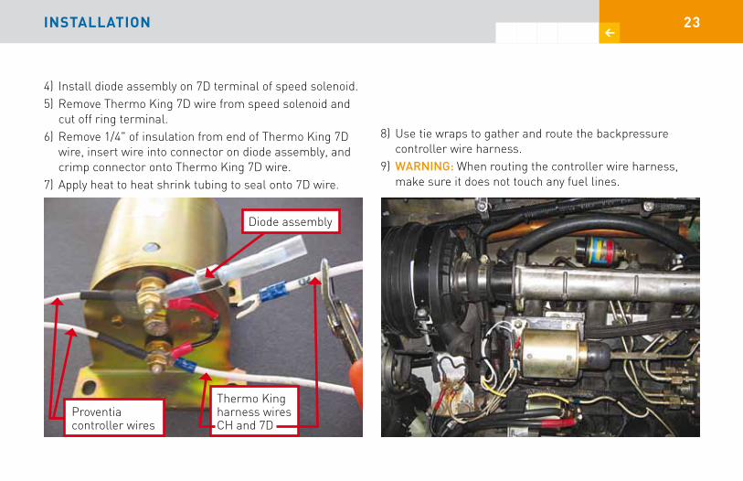
4) Install diode assembly on 7D terminal of speed solenoid.5) Remove Thermo King 7D wire from speed solenoid and
cut off ring terminal.6) Remove 1/4" of insulation from end of Thermo King 7D
wire, insert wire into connector on diode assembly, and crimp connector onto Thermo King 7D wire.
7) Apply heat to heat shrink tubing to seal onto 7D wire.
8) Use tie wraps to gather and route the backpressure controller wire harness.
9) WARninG: When routing the controller wire harness, make sure it does not touch any fuel lines.
INSTALLATION
Diode assembly
Thermo King harness wires CH and 7D
Proventia controller wires

24
INSTALL LAbELSTOOLS: Rag and degreaserPARTS: CARB VDECS label, ULSD fuel label
1) Remove CARB VDECS label, which is tie-wrapped in a plastic bag to the FTF.
2) Clean and degrease the engine surface before installing the label. Install label so it is visible to a CARB inspector when opening the TRU service doors.
INSTALLATION

25
3) Install the ULSD fuel label next to filler cap on TRU fuel tank. Clean and degrease the surface before installing the label.
hOW bACKPRESSuRE CONTROLLER WORKS The backpressure controller measures when there is too much soot accumulated inside the FTF during low-speed TRU operation. When the controller measures 2.5 psi backpressure, it will force the TRU to run in high speed by energizing the speed solenoid for 10 minutes by putting +12V at the 7D solenoid terminal. Operating at high speed will regenerate and reduce the soot accumulated inside the FTF.
After 10 minutes at high speed, the controller will return the TRU to low-speed operation. After 5 minutes at low-speed operation, if the controller again detects a 2.5 psi backpressure, it will energize the high-speed solenoid for another 10 minutes. The controller will repeat this sequence until the soot is sufficiently reduced inside the FTF. no operator intervention is required for controller to function properly.
INSTALLATION

26
ChECK PROPER OPERATION Of bACKPRESSuRE CONTROLLER AfTER COMPLETINg INSTALLATIONTOOLS: Pliers, pressurizer
1) To test if controller is functioning correctly, temporarily remove silicone hose from the backpressure tube and connect hose to the pressurizer.
2) Reconnect positive battery cable. Start TRU and run in low speed. Squeeze pressurizer until yellow indicator line is in middle of green range on gauge. This will cause controller to shift TRU into high speed. If controller doesn’t respond, see troubleshooting section on page 29. Remove pressurizer and reconnect silicone hose.
INSTALLATION

27
WARRANTy REgISTRATION ANd INSTALLER’S ChECKLISTAfter installation of the Proventia FTF system, register at www.proventiafilters.com/warranty.html and provide the following info to FTF distributor who will keep it for 4 years:
TRU owner’s name: _________________________________TRU owner’s contact phone number: __________________TRU owner’s e-mail _________________________________Installer’s name: ___________________________________Installer’s contact phone number: _____________________Installer’s e-mail ___________________________________Installation date: ___________________________________TRU hourmeter reading on installation date: _______ hoursTRU model name: (SBIII, Super II, Sentry): _____________TRU unit serial number: _____________________________TRU unit model year:________________________________TRU engine model: (Isuzu se2.2, Isuzu di2.2, Yanmar TK482, Yanmar TK486, etc.): ______________________________TRU engine serial number: __________________________Proventia FTF serial number: _________________________Oil consumption: _____________________ ounces/50 hoursInjectors replaced at : _______________ hourmeter readingInstaller initial that oil rate was measured and injectors were replaced _______________
CARb IdENTIfICATION NuMbER (IdN) REgISTRATION After installing the Proventia FTF system, the TRU owner may apply for CARB IDN at: www.arb.ca.gov/diesel/tru/application.htm
CLEANINg ThE fTf ANd SAfE ASh-hANdLINg guIdELINESIf there is excessive ash accumulation within the FTF (see page 30), the FTF will need to be cleaned. Clean the FTF by removing it from the TRU and blowing compressed air into the FTF outlet (seal around air hose), in the direction opposite of the exhaust flow. However, ash that would be blown out of the FTF inlet must be collected using a vacuum with a HEPA filter that collects the particulates for hazardous waste disposal. Call 800-609-4021 for recommendations of companies capable of removing ash from the FTF. Individuals who own, operate, or maintain diesel engines equipped with diesel particulate filters must manage hazardous ash waste generated by these devices. Follow ash-handling guidelines as prescribed by CARB at: www.arb.ca.gov/diesel/tru/documents/ashguide.pdf
WARRANTY & CARB REGISTRATION • CLEANING, ASH HANDLING

28 WIRINg dIAgRAM fOR bACKPRESSuRE CONTROLLER

29
TROubLEShOOTINgPROBLEM CAUSE SOLUTiOn
TRU does not shift to high-speed mode when backpressure is 2.5 psi at low-speed mode.
Leak in backpressure fitting, back-pressure tube, or silicone hose
Check for and repair leaks in the backpressure fitting, tube, or hose.
Faulty backpressure switch inside controller box
Check if switch contacts close when pressure is greater than 2.5 psi. If not, replace switch.
#2 Wire is disconnected from starter solenoid terminal
Terminal C on timer module should always be +12V. If not, check 5 amp in-line fuse on controller harness. Also, check for continuity of #2 wire from starter solenoid terminal up to C terminal on timer module.
#7D Wire is disconnected from speed solenoid
Put +12V on terminal #1 on timer module. 7D wire on speed solenoid should go to +12V for 10 minutes. If not, check for continuity of 7D wire from speed solenoid terminal up to NO terminal on timer module.
CH Wire is disconnected from speed solenoid
Check if terminal #2 on timer module is grounded. If not, check for continuity of CH wire from speed solenoid terminal up to #2 terminal on timer module.
Faulty timer module inside controller box
Put +12V on terminal #1 on timer module. NO terminal on timer should go to +12V for 10 minutes. If not, replace timer module.
TROubLEShOOTINg

30
PROBLEM CAUSE SOLUTiOn
TRU repeatedly shifts to high speed for 10 minutes, then low speed for 5 minutes.
Faulty Backpressure switch inside controller box
Check if backpressure switch contacts are open when TRU is not running. If not, replace switch. If switch is okay, proceed to next section.
Backpressure indicator gauge is in the red service range.
Soot or ash accumulation inside of FTF
Check if yellow gauge line in backpressure indicator gauge is within red service range during high-speed operation (see picture on page 4). If so, this is an indication that the FTF may have an excessive accumulation of soot or ash. The soot can be regenerated (cleaned out of the FTF) by running at high speed for 10 minutes and then shutting TRU off manually for 5 minutes. Repeat this cycle 5 times, then check backpressure indicator gauge reading again. If the yellow gauge line in backpressure indicator gauge continues to be within the red service range, this is an indication that the FTF may have an excessive accumulation of ash. Follow the filter cleaning and ash guidelines on page 27.
TROubLEShOOTINg

31TROubLEShOOTINg
PROBLEM CAUSE SOLUTiOn
Black smoke is visible from exhaust during steady speed operation
Poor combustion Visible smoke is normal when TRU shifts from low- to high-speed operation or high- to low-speed operation. If black smoke is visible during steady speed operation, injectors need to be serviced or replaced.
To service the TRU engine injectors, follow the TRU engine manufacturer guidelines:
a. Check the injector spray pattern on a nozzle test stand. The injector spray pattern should have four good sprays with no dripping.
b. Check the opening pressure of the nozzles:i. Yanmar injectors should be 2,800 to 3,000 psi. Isuzu injectors
should be 2,633 to 2,704 psi.
ii. Adjust nozzle opening pressure with shims as needed to meet the specification.

32
PARTS LISTReplacement parts available at www.proventiafilters.com.
PART# DESCRiPTiOnF01548 FLOW THROUGH FILTER, FTF
T001 INSULATION WITH SNAPS
T002 INSULATION BLANKET, EXHAUST MANIFOLD
T031 FTF MOUNTING CLAMPS
T004 BACK PRESSURE INDICATOR GAUGE
T033 FTF CONTROLLER ASSEMBLY (includes T014 & T015)
T007A EXHAUST CLAMP, R45
T008 HOSE, 0.17” ID X 14”
T009 TEE FITTING, BRASS
T010 SPRING CLAMP FOR SILICONE HOSE
T011 BACKPRESSURE TUBE
T012 BACKPRESSURE FITTING
T013 ULSD FUEL LABEL
T014 BACKPRESSURE SWITCH
T015 TIMER MODULE
TO17 PRESSURIZER
T050 DIODE ASSEMBLY
PARTS LIST

33
WARRANTy STATEMENTSyOuR WARRANTy RIghTS ANd ObLIgATIONSProventia Americas, LLC will warrant the Proventia FTF for the Transport Refrigeration Unit (TRU) for which it is sold or leased to be free from defects in design, materials, workmanship, or operation of the Proventia FTF that cause the Proventia FTF to fail to conform to the emission control performance level the Proventia FTF was verified to, or to the other requirements of the California Code of Regulations Title 13CCR sections §2700-2706 and 2710 for the period of 4 years, or 2,600 hours, whichever occurs first, provided there has been no abuse, neglect, or improper maintenance of the TRU, TRU engine, or Proventia FTF system, as specified in the owner’s manuals. Where a warrantable condition exists, this warranty also covers the TRU engine from damage caused by the Proventia FTF system, subject to the same exclusions for abuse, neglect, or improper maintenance of the TRU or TRU engine. Please review the owners manuals for other warranty information. The Proventia FTF system may include a core
part (e.g. particulate filter) as well as hoses, connectors, a backpressure monitor, and other emission-related assemblies. Where a warrantable condition exists, Proventia will repair or replace the FTF system at no cost to you including diagnosis, parts, and labor.
WARRANTy COVERAgEFor a TRU engine used in a TRU, the warranty period is 4 years or 2,600 hours of operation, whichever occurs first. If any emissions-related part of the Proventia FTF system is defective in design, materials, workmanship, or operation of the Proventia FTF system thus causing the Proventia FTF system to fail to conform to the emission control performance level it was verified to, or to the requirements in the California Code of Regulations Title 13CCR sections §2700-2706 and 2710, within the warranty period, as defined above, Proventia Americas, LLC will repair or replace the Proventia FTF system, including parts and labor.
In addition, Proventia Americas, LLC will replace or repair the TRU engine components to the condition they were in prior to the failure, including parts and labor, for damage to the TRU engine proximately caused by the Proventia
WARRANTy STATEMENTS

34
FTF system. This also includes those relevant diagnostic expenses in the case in which a warranty claim is valid. Proventia Americas, LLC may, at its option, instead pay the fair market value of the TRU engine prior to the time the failure occurs.
OWNER’S WARRANTy RESPONSIbILITyAs the TRU and Proventia FTF system owner, you are responsible for performing the required maintenance described in the TRU and Proventia FTF owners manuals. Proventia Americas, LLC recommends that you retain all maintenance records and receipts for maintenance expenses for your TRU and Proventia FTF system. If you do not keep your receipts or fail to perform all scheduled maintenance, Proventia Americas, LLC may have grounds to deny warranty coverage. You are responsible for presenting your TRU and Proventia FTF system to a Proventia Americas, LLC dealer as soon as a problem is detected. The warranty repair or replacement should be completed in a reasonable amount of time, not to exceed 30 days. If a replacement is needed, this may be extended to 90 days, should a replacement not be available, but must be performed as soon as a replacement becomes available.
If you have questions regarding your warranty rights and responsibilities, contact Proventia Americas, LLC at 800-609-4021 or the California Air Resources Board at Stationary Source Division - TRU, 1001 I Street, Sacramento, CA 95814, (888) 878-2826, or electronic mail: [email protected]
The installer will furnish the Proventia FTF owner with a copy of the following statement:
yOuR WARRANTy RIghTS ANd ObLIgATIONS(Installer’s name) ___________________ (Installer’s phone number) ____________________ will warrant that the installation of the Proventia FTF system is free from defects in workmanship or materials which cause the Proventia FTF to fail to conform to the emission control performance level it was verified to or to the requirements in the California Code of Regulations Title 13CCR sections §2700-2706. The warranty period and the extent of the warranty coverage provided by the installer will be the same as the warranty provided by Proventia Americas, LLC, and the same exclusions apply.
WARRANTy STATEMENTS

35
OWNER’S WARRANTy RESPONSIbILITyAs the TRU owner and Proventia FTF system owner, you are responsible for presenting your TRU and Proventia FTF system to the installer as soon as a problem with the installation is detected. If you have questions regarding your warranty rights and responsibilities, you should contact the Installer of the Proventia FTF system or the California Air Resources Board at Stationary Source Division - TRU, 1001 I Street, Sacramento, CA 95814, (888) 878-2826, or electronic mail: [email protected]
WARRANTy STATEMENTS

5/11/09