protect – mns motor management insum - abb · pdf file · 2015-05-08protectit...
TRANSCRIPT
ProtectIT – MNS Motor Management INSUM®
Technical Information
adaptable value
innovative value
intelligent value
proactive value
resourceful value
responsible value
activate value
communicative value

The Industrial IT wordmark and all product names in the form XXXXX IT are registered
or pending trademarks of ABB.
Emax is a registered trademark of ABB SACE Spa.
MNS, INSUM and PRODAT are registered trademarks of ABB Schaltanlagentechnik GmbH.
Microsoft, Windows and Windows NT are registered trademarks of Microsoft Corporation.
LON, LonTalk, LONWORKS, NEURON are registered trademarks of Echelon Corporation.
MODBUS is a registered trademark of Schneider Automation.
PROFIBUS is a registered trademark of PROFIBUS Nutzerorganisation e.V. (PNO).
Technical descriptions relate to Protect IT - MNS Motor Management INSUM, Release 2.3/1.
This product has been certified by ABB Group as Industrial IT EnabledTM- Information Level. All product
information is supplied in interactive electronic format, based on ABB Aspect ObjectTM technology.
The Industrial IT commitment from ABB ensures that every enterprise building block is equipped with the
integral tools necessary to install, operate, and maintain it efficiently throughout the product lifecycle.
The information in this document is subject to change without notice and should not be construed as a
commitment by ABB. ABB assumes no responsibility for any errors that may appear in this document. In
no event shall ABB be liable for direct, indirect, special, incidental, or consequential damages of any nature
or kind arising from the use of this document, nor shall ABB be liable for incidental or consequential damages
arising from use of any software or hardware described in this document.
This document and parts thereof must not be reproduced or copied without ABB's written permission, and
the contents thereof must not be imparted to a third party nor be used for any unauthorized purpose. The
software described in this document is furnished under a license and may be used, copied, or disclosed
only in accordance with the terms of such license.
All rights reserved.
Copyright © 2004 ABB Schaltanlagentechnik GmbH, Ladenburg

ProtectIT – MNS Motor Management INSUM
INSUM is an intelligent system based on PowerIT - Low Voltage Switchgear MNS, offering superi-
or protection, control and monitoring for user-optimized motor management.
Relevant information from the process – including timely alarms – enable plant operators to make
smart decisions on process conditions. Plant availability is significantly improved through preven-
tive actions. Data with quality far beyond conventional motor protection or remote control tech-
nology, is utilized by engineering crews for detailed system analysis and need-based maintenance.
This brochure provides an overview of the INSUM System, its components, their functions and
benefits as well as relevant technical data. Please refer also to our website at www.abb.com/mns.

System Overview
4
Control system overview showing typical low
voltage energy distribution and motor control
center communicating upwards to Process
Control Systems and sideways to engineering
and maintenance stations (INSUM OS). Avail-
able in simplex or dual-redundant configuration.
Dual-redundant illustrated.
System Overview
Integrated Tier Switch (ITS)SlimLine fitted in MNS LVswitchgear
Process Control System,Energy Management System,Emergency Shut down System
Site-Wide E
therne
t LAN Dua
l-Red
undan
t

Motor Control Unit (MCU)in Motor Starter
PR 112 ProgrammableRelease for Emax air circuit breaker
INSUM CommunicationsUnit (ICU)
INSUM OSshown connectedvia Ethernet TCP/IP
INSUM OS
PROFIBUS DP - M
ODBUS RTU-LON

System Overview
6
INSUM OperatorStation (INSUM OS)
INSUM MMIMan Machine Interface
Communication■ The INSUM Communications Unit (ICU) is
the switchgear hub for simultaneous communi-
cation to higher level control systems via gate-
way modules. A variety of protocols is avail-
able such as: MODBUS RTU, PROFIBUS DP,
LON® and Ethernet TCP/IP. Up to 128 field
devices distributed over 4 subnets are con-
nected to one ICU.
Human System Interface■ Man Machine Interface (MMI) is the switch-
room operator interface. It enables the opera-
tor to configure control and monitor all devices
connected to one ICU.
■ INSUM Operator Station (INSUM OS) is
a high-performance Microsoft WindowsTM
based engineering and maintenance system,
which allows connection to multiple ICUs for
motor management. It usually connects in
parallel to the overall plant-wide Process
Control System (PCS).
Field Devices ■ Motor Control Unit (MCU) is an intelligent
micro-processor motor protection and control
relay, one MCU is used per motor starter.
■ The Programmable Release PR 112 is an
intelligent, micro-processor trip unit for ABB
air circuit breakers. One PR unit is required
per breaker.
■ Integrated Tier Switch (ITS) is an intelligent
switch fuse disconnector providing fuse
measurements, status and reporting.
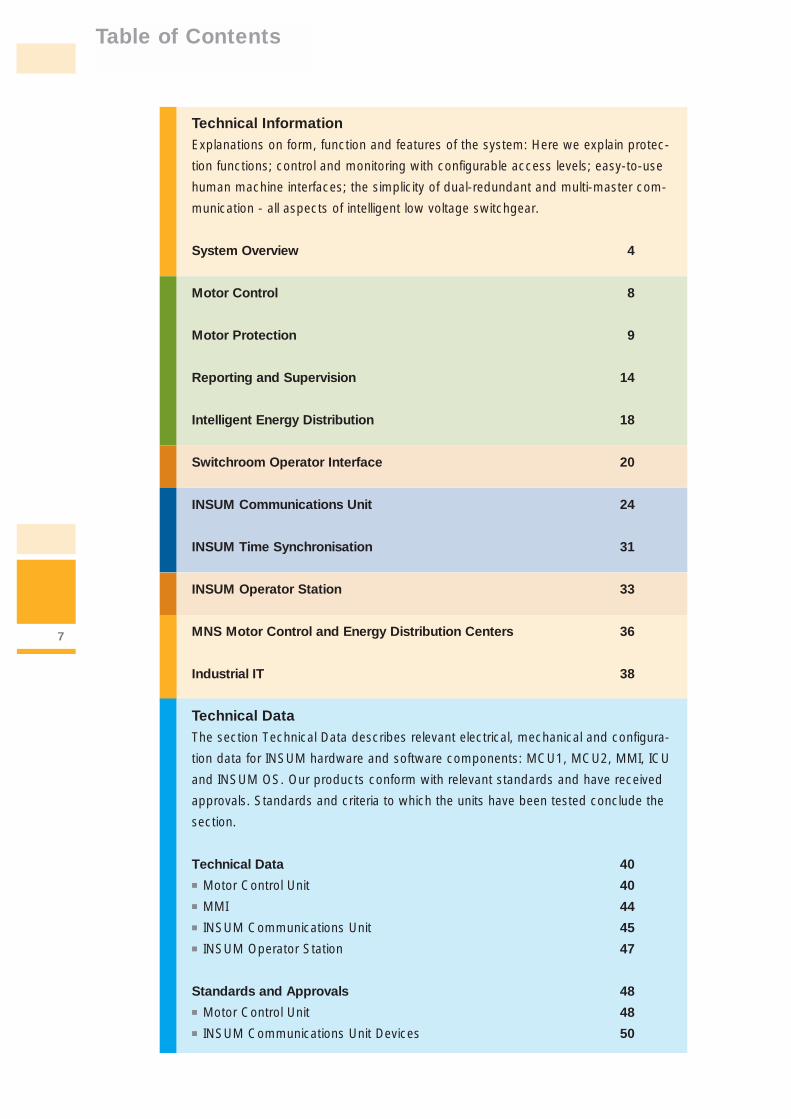
Table of Contents
7
Technical InformationExplanations on form, function and features of the system: Here we explain protec-
tion functions; control and monitoring with configurable access levels; easy-to-use
human machine interfaces; the simplicity of dual-redundant and multi-master com-
munication - all aspects of intelligent low voltage switchgear.
System Overview 4
Motor Control 8
Motor Protection 9
Reporting and Supervision 14
Intelligent Energy Distribution 18
Switchroom Operator Interface 20
INSUM Communications Unit 24
INSUM Time Synchronisation 31
INSUM Operator Station 33
MNS Motor Control and Energy Distribution Centers 36
Industrial IT 38
Technical DataThe section Technical Data describes relevant electrical, mechanical and configura-
tion data for INSUM hardware and software components: MCU1, MCU2, MMI, ICU
and INSUM OS. Our products conform with relevant standards and have received
approvals. Standards and criteria to which the units have been tested conclude the
section.
Technical Data 40■ Motor Control Unit 40■ MMI 44■ INSUM Communications Unit 45■ INSUM Operator Station 47
Standards and Approvals 48■ Motor Control Unit 48■ INSUM Communications Unit Devices 50

Motor Control
8
INSUM provides a combination of extensive
motor protection, control and monitoring using
just two standard microprocessor devices.
MCU1 provides motor protection, control and
monitoring for the most basic of applications,
whilst MCU2 provides additional functionality,
for the most complex and advanced applica-
tions. The INSUM system therefore offers a fit-
for-purpose solution.
From the most basic to the most complex in just two devices
Non R
ever
sing
DOL
MCU 1
MCU 2
Starter Types
Rever
sing
DOL
Non R
ever
sing
DOL R
emot
e Con
trol U
nit
Rever
sing
DOL
Rem
ote
Contro
l Uni
t
Non R
ever
sing
DOL L
atch
ed
Rever
sing
DOL L
atch
ed
Non R
ever
sing
Star
Del
ta
Rever
sing
Star
Del
ta
Non R
ever
sing
Two
Spee
d
Rever
sing
Two
Spee
d
Actua
tor
Auto-
Tran
sfor
mer
Soft-
Sta
rter
MCU mounted in withdrawable MNS drawer 8E/4. MCU executes control
commands from and reports status to remote control systems.

Motor Protection
9
The motor protection functions safeguard the
motor against the unwanted process or
mechanical stresses and strains. The protection
functions allow pre-sets for “Alarm Levels”
“Trip Levels” and “Trip Delays” thus protecting
your valuable assets – your mechanical and
electrical equipment – and safeguarding your
production.
The philosophy is simple to generate alarms
when the pre-set alarm level is reached. In this
condition the motor will not trip as long as the
“Trip Level” is not crossed. If the “Trip Level” is
crossed but is within the adjustable “Trip Delay”
the motor will not trip. If the “Trip Level” is
crossed and the “Trip Delay” expires the motor
will trip. In each event messages are generated.
The detailed information on the motor status
and configuration is communicated site-wide,
providing the plant operator with information
enabling preventive actions and educated deci-
sion to be made before plant status becomes
critical, ensuring plant operators are pro-active
in maximizing plant availability with unwanted
trips being avoided.
The protection functions are configurable and
can be enabled or disabled depending on the
requirement.
Additionally protection functions can be set to
trip only or alarm only. Protection functions are
suppressed during motor start up time and soft
start ramp time. The trip-reset modes can also
be configured for either of the following: ■ Auto Trip Reset ■ Remote Trip Reset■ Local Trip Reset ■ Remote & Local Trip Reset
Protecting your assets with all the protection you would ever need!
Motor Start
Trip delay
Trip level
Alarm level
Alarm and Trip data set according to motor manufacturer’s specification and process needs
Alarm issuedAlarm issued
Motor trips
Trip delay not exceeded
Motor keeps running
Normal LoadNormal Load Temporary Fault
Alarm level, Trip level and Trip delay Illustrated
Continuous Fault
Trip delay

Motor Protection
10
Thermal Overload Protection (TOL) protects the
motor against overheating. The motor thermal
condition is simulated by calculation both when
running and when stopped. The resulting cacu-
lation i.e. thermal capacity is stored in the thermal
register. The value stored in the thermal register
is communicated via the ICU to other devices
capable of interpreting the information.
TOL protection is particulary useful during plant
start-up where frequent motor starting occurs.
■ Functionality of the thermal model according
to IEC 947-4-1
■ MCU calculates “Time to Trip” and “Time to
Reset”. Additionally a message “TOL Reset
Level Reached” is generated to inform the user
of a possibility to reset the trip.
■ Automatic restart is also available (MCU2)
following a TOL trip, if activated the motor
will start automatically when it has cooled
down and the trip has reset. The restart will
take place in the direction or speed that
were active prior to the trip.
■ In some process applications it may be bene-
ficial to bypass the TOL protection for short
periods. If the “TOL Bypass” command is
given after the TOL alarm, the thermal capacity
is allowed to rise up to 200 % before tripping.
This feature cannot be activated for EEx e
applications.
Motor ProtectionFunction
TOL Standard
TOL EEx e
MCU 1 MCU 2 Alarm Trip Trip Level Level Delay
■ ■ ■ ■
■ ■ ■

Motor Protection
11
Description
Supports TOL standard. The MCU uses the highest measured phase current for the calculation.The thermal capacity calculation considers actual load, phase unbalance and motor ratedload in ambient temperature.
Supports TOL EEx e. Takes into consideration stall/nominal current ratio and the max. tem-perature allowed by the environment class definition. Data provided by the motor manufac-turer is directly entered as setting without additional calculations.
ThermalCapacity
100%
startinhibit
Start Running Stopped Start Stopped Next Start
time
earliest manual orautomatic start
start command
stop commandThermal capacity must be below “Start Inhibit” to allow a motor start.
Thermal Overload Protection Illustrated
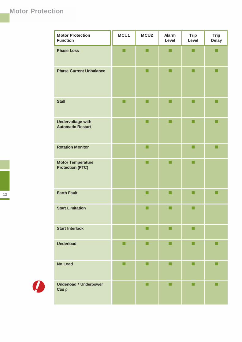
12
Motor Protection
Motor ProtectionFunction
Phase Loss
Phase Current Unbalance
Stall
Undervoltage withAutomatic Restart
Rotation Monitor
Motor TemperatureProtection (PTC)
Earth Fault
Start Limitation
Start Interlock
Underload
No Load
Underload / UnderpowerCos ρ
MCU1 MCU2 Alarm Trip Trip Level Level Delay
■ ■ ■ ■ ■
■ ■ ■ ■
■ ■ ■ ■ ■
■ ■ ■ ■
■ ■ ■
■ ■ ■
■ ■ ■ ■
■ ■ ■
■ ■ ■
■ ■ ■ ■ ■
■ ■ ■ ■ ■
■ ■ ■ ■
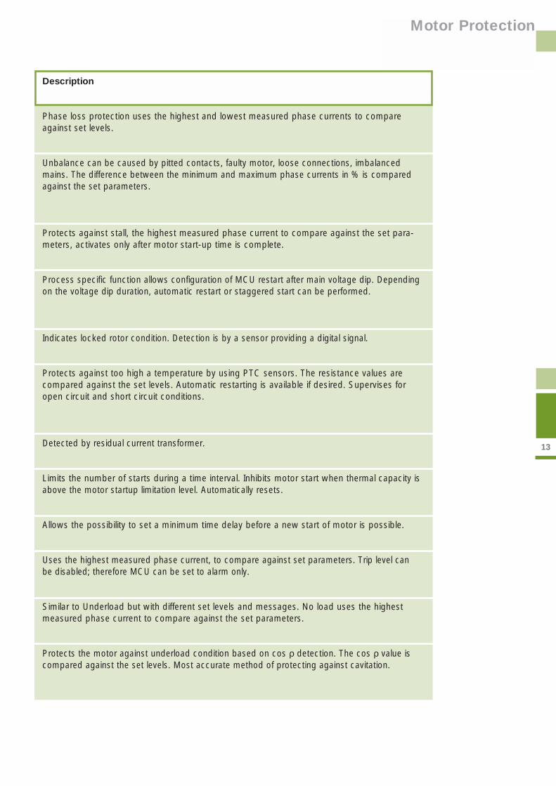
Motor Protection
13
Description
Phase loss protection uses the highest and lowest measured phase currents to compareagainst set levels.
Unbalance can be caused by pitted contacts, faulty motor, loose connections, imbalancedmains. The difference between the minimum and maximum phase currents in % is comparedagainst the set parameters.
Protects against stall, the highest measured phase current to compare against the set para-meters, activates only after motor start-up time is complete.
Process specific function allows configuration of MCU restart after main voltage dip. Dependingon the voltage dip duration, automatic restart or staggered start can be performed.
Indicates locked rotor condition. Detection is by a sensor providing a digital signal.
Protects against too high a temperature by using PTC sensors. The resistance values arecompared against the set levels. Automatic restarting is available if desired. Supervises foropen circuit and short circuit conditions.
Detected by residual current transformer.
Limits the number of starts during a time interval. Inhibits motor start when thermal capacity isabove the motor startup limitation level. Automatically resets.
Allows the possibility to set a minimum time delay before a new start of motor is possible.
Uses the highest measured phase current, to compare against set parameters. Trip level canbe disabled; therefore MCU can be set to alarm only.
Similar to Underload but with different set levels and messages. No load uses the highestmeasured phase current to compare against the set parameters.
Protects the motor against underload condition based on cos ρ detection. The cos ρ value iscompared against the set levels. Most accurate method of protecting against cavitation.

14
Reporting andSupervision
INSUM continuously supervises the other trip
situations as well as keeps track of maintenance
data. The below information is available to the
user via communication links or at the MMI dis-
play. Analog values are given as true rms values.
Messages are generated on status change or
when thresholds are exceeded indicating that
a certain planned or unplanned system status
may be reached. These messages may be
alarms or trips generated by the MCU.
More information, better decision making, increased productivity
Reporting & SupervisionFunction
Motor Status
Phase Currents
Analog Output
Calculated Thermal Capacity
Time to Trip
Time to Reset
Phase Voltages
Power Factor
Active Power
Reactive Power
Earth Fault Current
Frequency
General Purpose Digital Input
General Purpose Digital Output
Moto
r S
tatu
s an
d V
alues
MCU 1 MCU 2
■ ■
■ ■
■
■ ■
■ ■
■ ■
■
■
■
■
■
■
■
■

15
Reporting andSupervision
Description
Motor status such as On / Off; Open / Closed; Tripped.
Three motor phase currents. Absolute and relative values.
Highest phase current delivered for analog indication, e.g. at the Local Control Panel.
Thermal capacity calculated from motor and environmental parameters.
Estimated time to reach 100% thermal capacity.
Estimated cool-down time at which the thermal capacity of the motor allows a restart.
Three phase voltages. Absolute measured values.
Calculated value.
Active power as absolute value.
Reactive power as absolute value.
Earth fault current measured as absolute value.
Frequency of the electrical power system, absolute value.
Two digital inputs available for read out status of an external device (i.e. remote I/O).
Two digital outputs are available for external control. Can be driven by commands receivedfrom the process control system.
All messages are time tagged with the internal
time when they occur and the data is reported
to the field bus.
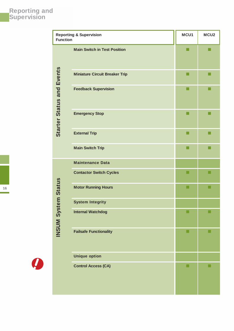
16
Reporting andSupervision
Reporting & SupervisionFunction
Main Switch in Test Position
Miniature Circuit Breaker Trip
Feedback Supervision
Emergency Stop
External Trip
Main Switch Trip
Maintenance Data
Contactor Switch Cycles
Motor Running Hours
System Integrity
Internal Watchdog
Failsafe Functionality
Unique option
Control Access (CA)
Sta
rter
Sta
tus
and E
vents
INS
UM
Sys
tem
Sta
tus
MCU1 MCU2
■ ■
■ ■
■ ■
■ ■
■ ■
■ ■
■ ■
■ ■
■ ■
■ ■
■ ■

17
Reporting andSupervision
Description
MCU monitors the main switch, I/O status and phase currents. Current based protection func-tions are disabled to allow testing. If any phase current is detected, the MCU issues a commandto trip the contactor.
MCU executes a contactor trip when Miniature Circuit Breaker Input is activated.
Following receipt of a command signal, the MCU monitors the status of motor and contactorto ensure correct execution. Status is checked by using feedback signals and by current mea-surement. When enabled will cyclically check the above.
When the Emergency Stop is operated the MCU executes a contactor trip. The release of theEmergency Stop button will not start the motor.
MCU detects an external trip, via unit I/O. When trip input is activated, MCU executes a con-tactor trip.
Main switch input indicates the status of motor feeder main switch. This input if activated willexecute a contactor trip.
Each complete close-open cycle is counted and updated. When the contactor switch cyclelimit is exceeded MCU initiates an alarm.
The MCU counts the motor running hours. An alarm is initiated when the predefined operatingrunning hours limit is exceeded.
An internal watchdog relay. In series with the contactor control line voltage, cyclically refreshedby the microprocessor. When no refreshing occurs, the contactor watchdog relay will open.
Supervises the network communication. If a loss of communications is detected the failsafeactivates with either one of the following pre-parameterized functions: No Operation, StartMotor Direction 1, Start Motor Direction 2, or Stop Motor. By selecting the correct actionsappropriate to the process, total plant shutdown can be avoided.
Control of devices is limited to one host at any time to ensure system integrity. There are up to16 levels of CA that can be user defined as to whom has the highest authority, usually the PCS.A facility exists that in the event of a failure in the PCS communications link, CA is released tothe desired authority ensuring full plant availability.

18
Intelligent EnergyDistribution
Microprocessor-based components offer an
efficient and flexible solution integrating aspects
of INSUM motor control and energy distribution
management.
As part of one integrated solution protection,
control and monitoring of the energy distribution
reaches from circuit breakers to fuse switches.
The Intelligent Circuit Breaker
The PR112/PD-L release for the Emax range
of air circuit breakers provides communication
within the INSUM system. The programmable
release with integrated communication and
control functions PR112/PD-L allows a wide
range of information to be communicated.
Breaker status, alarm and maintenance infor-
mation is communicated upstream where as
control commands and configuration settings
as well as time synchronization is sent down-
stream.
INSUM – Combining Intelligent Starters, Intelligent Circuit Breakers,and Intelligent Fuse Switches, for that Integrated Solution.
Supervision and Protection Function
Breaker Status and Values■ State and position of the circuit breaker■ Phase, neutral and earth currents
Protection■ Function: Overload (L). Selective short circuit (S). Instantaneous short
circuit (I). Earth fault (G). Over-temperature (T)■ Alarms for protection timing of L, S and G■ Alarms for protection trip of L, S, I, G and T■ Overload and excessive temperature■ Memorization of fault currents
Maintenance Data■ Alarm for contact wear■ Contact wear■ Number of total and manual operations■ Number of total trips per protection functions (L, S, I, G and T)
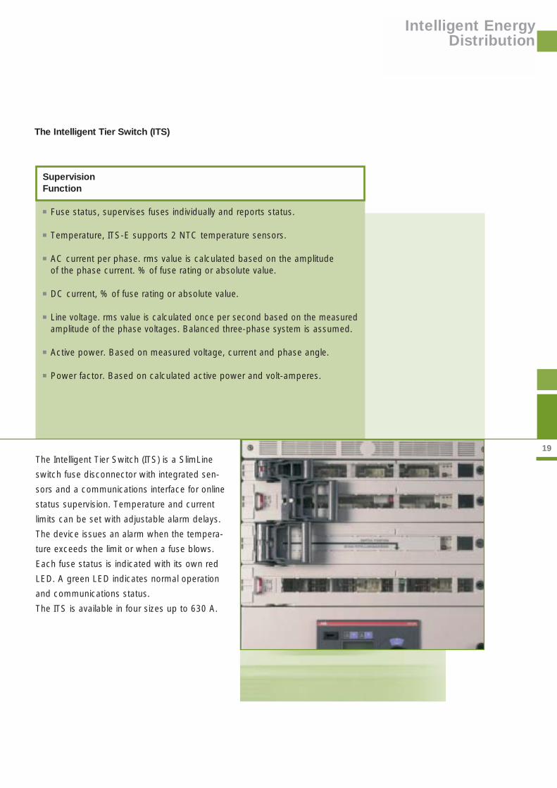
19The Intelligent Tier Switch (ITS) is a SlimLine
switch fuse disconnector with integrated sen-
sors and a communications interface for online
status supervision. Temperature and current
limits can be set with adjustable alarm delays.
The device issues an alarm when the tempera-
ture exceeds the limit or when a fuse blows.
Each fuse status is indicated with its own red
LED. A green LED indicates normal operation
and communications status.
The ITS is available in four sizes up to 630 A.
The Intelligent Tier Switch (ITS)
Supervision Function
■ Fuse status, supervises fuses individually and reports status.
■ Temperature, ITS-E supports 2 NTC temperature sensors.
■ AC current per phase. rms value is calculated based on the amplitude of the phase current. % of fuse rating or absolute value.
■ DC current, % of fuse rating or absolute value.
■ Line voltage. rms value is calculated once per second based on the measuredamplitude of the phase voltages. Balanced three-phase system is assumed.
■ Active power. Based on measured voltage, current and phase angle.
■ Power factor. Based on calculated active power and volt-amperes.
Intelligent EnergyDistribution

20
SwitchroomOperator Interface
Operator interface to the intelligent MNS System
in the switchroom is via the INSUM MMI (Man
Machine Interface). It displays measured values
and status information of all (up to 128) field
devices connected to a particular INSUM Com-
munications Unit (ICU): motor control units, circuit
breaker programmable release and fuse switches,
as well as communication devices.
The context sensitive function keys allow for the
control of these devices and for configuring their
functions by defining their respective parameters.
Access to the menu and functions can be de-
fined by using an electronic data key, the INSUM
Data Key, with configurable privileges.
All information is sorted in menus and displayed
on the MMIs 6-line 21 character LCD. The en-
coder wheel provides easy navigation through
lists of data, parameters, alarms and trips, via
clearly structured menus and sub-menus. The
ENTER, ESCAPE and HOME key assists the
navigation through the different menus resulting
in a very friendly, easy to use interface.
Data and Control at the Operator’s Fingertips – The INSUM MMI
Slot for INSUM Data Key LCD Display

21
SwitchroomOperator Interface
Function Keys ENTER Key Encoder Wheel
ALARM Indicator & LIST Key TRIP Indicator & LIST Key HOME Key
ESCAPE Key
<MA IN MENU>
SYSTEMCONFIGURAT ION
OPERATE
PARAMETER
ALARM LISTS
UPDATE DATABASE
22
SwitchroomOperator Interface
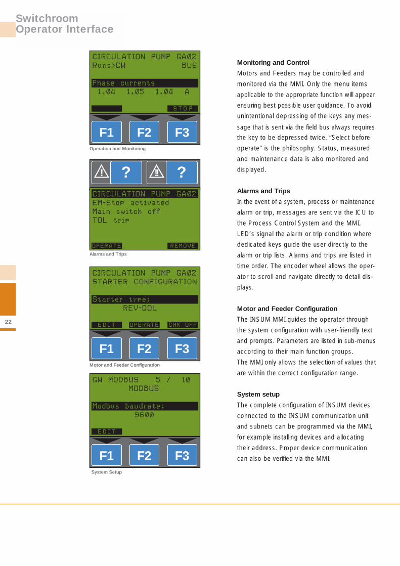
Monitoring and Control
Motors and Feeders may be controlled and
monitored via the MMI. Only the menu items
applicable to the appropriate function will appear
ensuring best possible user guidance. To avoid
unintentional depressing of the keys any mes-
sage that is sent via the field bus always requires
the key to be depressed twice. “Select before
operate” is the philosophy. Status, measured
and maintenance data is also monitored and
displayed.
Alarms and Trips
In the event of a system, process or maintenance
alarm or trip, messages are sent via the ICU to
the Process Control System and the MMI.
LED’s signal the alarm or trip condition where
dedicated keys guide the user directly to the
alarm or trip lists. Alarms and trips are listed in
time order. The encoder wheel allows the oper-
ator to scroll and navigate directly to detail dis-
plays.
Motor and Feeder Configuration
The INSUM MMI guides the operator through
the system configuration with user-friendly text
and prompts. Parameters are listed in sub-menus
according to their main function groups.
The MMI only allows the selection of values that
are within the correct configuration range.
System setup
The complete configuration of INSUM devices
connected to the INSUM communication unit
and subnets can be programmed via the MMI,
for example installing devices and allocating
their address. Proper device communication
can also be verified via the MMI.
F1 F3F2
F1 F3F2
F1 F3F2
?! ?!!
System Setup
Operation and Monitoring
Alarms and Trips
Motor and Feeder Configuration
CIRCULATION PUMP GA0/2
Runs>CW BUS
Phase currents
1.0/4 1.0/5 1.0/4 A
S T O P
CIRCULATION PUMP GA0/2
EM-Stop activated
Main switch off
TOL trip
REMOVEOPERATE
CIRCULATION PUMP GA0/2
STARTER CONFIGURATION
Starter type:
REV-DOL
CHK OFFE D I T OPERATE
GW MODBUS 5 / 10/
MODBUS
Modbus baudrate:
960/0/
E D I T
23
SwitchroomOperator Interface
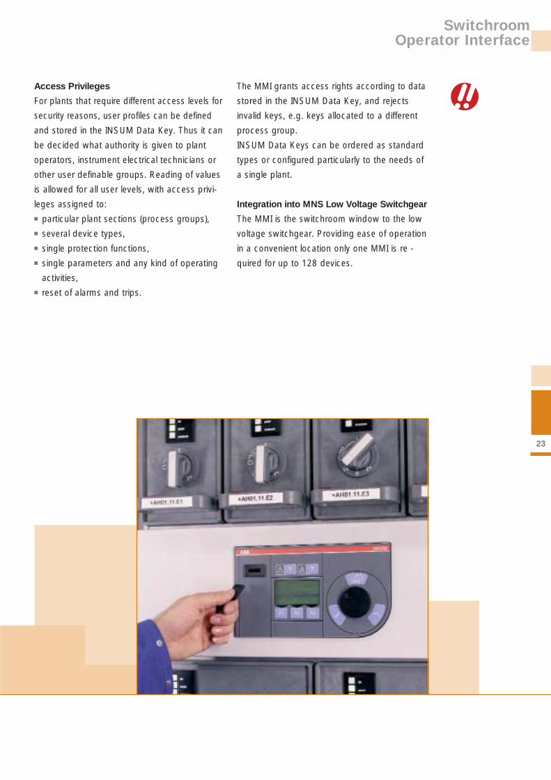
Access Privileges
For plants that require different access levels for
security reasons, user profiles can be defined
and stored in the INSUM Data Key. Thus it can
be decided what authority is given to plant
operators, instrument electrical technicians or
other user definable groups. Reading of values
is allowed for all user levels, with access privi-
leges assigned to: ■ particular plant sections (process groups), ■ several device types,■ single protection functions,■ single parameters and any kind of operating
activities,■ reset of alarms and trips.
The MMI grants access rights according to data
stored in the INSUM Data Key, and rejects
invalid keys, e.g. keys allocated to a different
process group.
INSUM Data Keys can be ordered as standard
types or configured particularly to the needs of
a single plant.
Integration into MNS Low Voltage Switchgear
The MMI is the switchroom window to the low
voltage switchgear. Providing ease of operation
in a convenient location only one MMI is re -
quired for up to 128 devices.

24
INSUM Communications Unit (ICU)
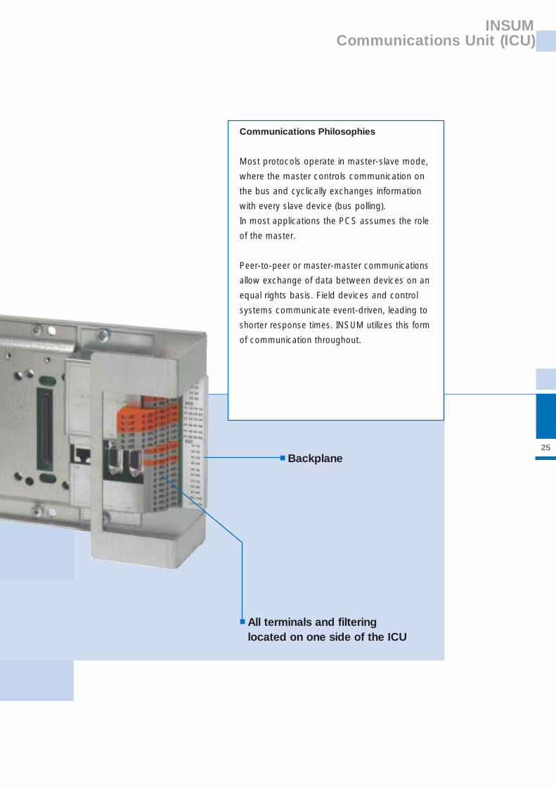
The INSUM Communications Unit (ICU) is the
switchgear communications hub for up to 128
devices consisting of MCUs, PR 112 and ITS
fuse switches. It directs and localizes bus com-
munication therefore optimizing network load
and response time. The ICU can maintain up to
three simultaneous connections to higher-level
control systems, making dual-redundant con-
figurations and multi-master communications an
integral part of the system design. The modular,
plug-in design allows configurations scalable to
application needs. All connections are located
on one side of the ICU for simple and reliable
wiring. The operator interface to all field devices
in the switch room (MMI) connects to the ICU.
These attributes lead to a cost-effective and very
flexible system design.
Collecting, filtering and distributing the right information to the rightpeople - site-wide!
■ Gateway■ Router
25
INSUM Communications Unit (ICU)
■ All terminals and filtering located on one side of the ICU
■ Backplane
Most protocols operate in master-slave mode,
where the master controls communication on
the bus and cyclically exchanges information
with every slave device (bus polling).
In most applications the PCS assumes the role
of the master.
Peer-to-peer or master-master communications
allow exchange of data between devices on an
equal rights basis. Field devices and control
systems communicate event-driven, leading to
shorter response times. INSUM utilizes this form
of communication throughout.
Communications Philosophies
26
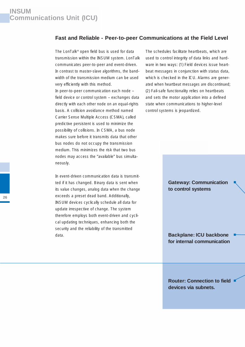
The LonTalk® open field bus is used for data
transmission within the INSUM system. LonTalk
communicates peer-to-peer and event-driven.
In contrast to master-slave algorithms, the band-
width of the transmission medium can be used
very efficiently with this method.
In peer-to-peer communication each node –
field device or control system – exchanges data
directly with each other node on an equal-rights
basis. A collision avoidance method named
Carrier Sense Multiple Access (CSMA), called
predictive persistent is used to minimize the
possibility of collisions. In CSMA, a bus node
makes sure before it transmits data that other
bus nodes do not occupy the transmission
medium. This minimizes the risk that two bus
nodes may access the “available” bus simulta-
neously.
In event-driven communication data is transmit-
ted if it has changed. Binary data is sent when
its value changes, analog data when the change
exceeds a preset dead band. Additionally,
INSUM devices cyclically schedule all data for
update irrespective of change. The system
therefore employs both event-driven and cycli-
cal updating techniques, enhancing both the
security and the reliability of the transmitted
data.
The schedules facilitate heartbeats, which are
used to control integrity of data links and hard-
ware in two ways: (1) Field devices issue heart-
beat messages in conjunction with status data,
which is checked in the ICU. Alarms are gener-
ated when heartbeat messages are discontinued;
(2) Fail-safe functionality relies on heartbeats
and sets the motor application into a defined
state when communications to higher-level
control systems is jeopardized.
Fast and Reliable - Peer-to-peer Communications at the Field Level
INSUM Communications Unit (ICU)
Backplane: ICU backbonefor internal communication
Router: Connection to fielddevices via subnets.
Gateway: Communication to control systems
■
■
■

27
INSUM Communications Unit (ICU)
The backplane is the core of the ICU and hosts
Gateways, Routers and the optional power
supply. The LON main bus communicates at
1250 kbps, providing sufficient bandwidth for
handling traffic to and from the subnets, which
communicate at 78 kbps. Up to four subnets,
two per Router, are supported by one backplane.
Up to 32 field devices: MCUs, PR112’s and ITS
fuse switches, are located on one subnet.
Utilizing multiple subnets with peer-to-peer com-
munication reduces access time to individual
devices and optimizes the network load by
localizing traffic. The system response time,
consisting of a command received at the ICU,
transmission to the field device, command exe-
cution and response back for collection is typi-
cally less than 200 ms.
Gateways provide connection and data filters for
communication of essential information to higher
level systems. With four Gateways connectable
to one ICU the INSUM system offers multi-master
capabilities as an integral part of the design. Two
ICUs configured in one system paired with peer-
to-peer communications at the field level provide
an inherently simple method for dual-redundant
communications down to the field device.
Connectivity and Communication
MMI
LON
INSUM OSEngineeringStation
Process Control System
RouterRouter
Backplane
MCU1
MCU...
MCU32
MCU1
MCU...
MCU32
PR1121
ITS...
ITS32
ITS1
PR112...
PR11216
Gateway- MODBUS- PROFIBUS DP- Ethernet
Gateway- MODBUS- PROFIBUS DP- Ethernet
GatewayINSUM OS Server- Ethernet
SystemClock
GPSReceiver
ICU internal communications: A sample configuration with 64 MCUs, 32 ITS and 16 PR 112 communicating on four subnets.
Subnet 1 Subnet 2 Subnet 3 Subnet 4
to other remoteINSUM OS Stations
to other System Clocks
28
INSUM Communications Unit (ICU)
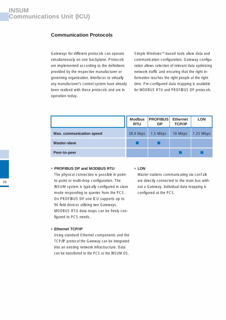
Gateways for different protocols can operate
simultaneously on one backplane. Protocols
are implemented according to the definitions
provided by the respective manufacturer or
governing organization. Interfaces to virtually
any manufacturer's control system have already
been realized with these protocols and are in
operation today.
Simple WindowsTM-based tools allow data and
communication configuration. Gateway configu-
ration allows selection of relevant data optimizing
network traffic and ensuring that the right in-
formation reaches the right people at the right
time. Pre-configured data mapping is available
for MODBUS RTU and PROFIBUS DP protocols.
■ PROFIBUS DP and MODBUS RTU
The physical connection is possible in point-
to-point or multi-drop configuration. The
INSUM system is typically configured in slave
mode responding to queries from the PCS.
On PROFIBUS DP one ICU supports up to
96 field devices utilizing two Gateways.
MODBUS RTU data maps can be freely con-
figured to PCS needs.
■ Ethernet TCP/IP
Using standard Ethernet components and the
TCP/IP protocol the Gateway can be integrated
into an existing network infrastructure. Data
can be transferred to the PCS or the INSUM OS.
■ LON
Master stations communicating via LonTalk
are directly connected to the main bus with-
out a Gateway. Individual data mapping is
configured at the PCS.
Communication Protocols
Max. communication speed
Master-slave
Peer-to-peer
Modbus PROFIBUS Ethernet LONRTU DP TCP/IP
38.4 kbps 1.5 Mbps 10 Mbps 1.25 Mbps
■ ■
■ ■
29
INSUM Communications Unit (ICU)
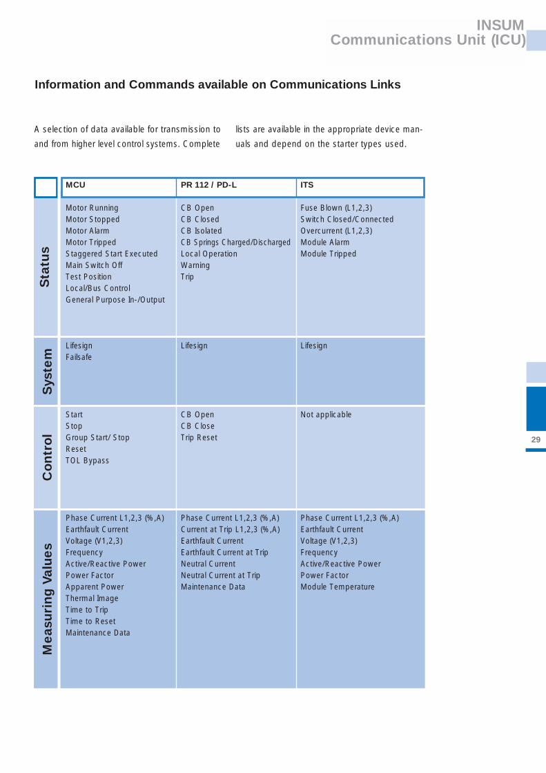
A selection of data available for transmission to
and from higher level control systems. Complete
lists are available in the appropriate device man-
uals and depend on the starter types used.
Information and Commands available on Communications Links
Sta
tus
Sys
tem
Contr
ol
Meas
uri
ng V
alues
MCU PR 112 / PD-L ITS
Motor Running CB Open Fuse Blown (L1,2,3)Motor Stopped CB Closed Switch Closed/ConnectedMotor Alarm CB Isolated Overcurrent (L1,2,3)Motor Tripped CB Springs Charged/Discharged Module AlarmStaggered Start Executed Local Operation Module TrippedMain Switch Off Warning Test Position TripLocal/Bus ControlGeneral Purpose In-/Output
Lifesign Lifesign LifesignFailsafe
Start CB Open Not applicableStop CB CloseGroup Start/ Stop Trip ResetResetTOL Bypass
Phase Current L1,2,3 (%,A) Phase Current L1,2,3 (%,A) Phase Current L1,2,3 (%,A)Earthfault Current Current at Trip L1,2,3 (%,A) Earthfault CurrentVoltage (V1,2,3) Earthfault Current Voltage (V1,2,3)Frequency Earthfault Current at Trip FrequencyActive/Reactive Power Neutral Current Active/Reactive PowerPower Factor Neutral Current at Trip Power FactorApparent Power Maintenance Data Module TemperatureThermal ImageTime to TripTime to ResetMaintenance Data

30
INSUM Communications Unit (ICU)
MCU PR 112 / PD-L ITS
TOL Alarm/Trip CB Undefined Fuse Blown (L1,2,3)Startup Inhibit Alarm/Trip CB Trip Overcurrent (L1,2,3)Phase Loss Alarm/Trip (L1,2,3) LC1 Opened Module Temperature Alarm/TripUnderload Alarm/Trip LC2 OpenedNo-load Alarm/Trip Unbalanced PhasesUnderload Cos Phi Alarm/Trip Harmonic DistortionStall Alarm/Trip Contact Wear Pre-alarmEarthfault Alarm/Trip Contact Wear AlarmPhase Unbalance Alarm/Trip Prot. L Pre-Alarm/Alarm/TripRotation Alarm/Trip Prot. S Alarm/TripTorque Trip Prot. I TripPTC Temperature Alarm/Trip Prot. G Alarm/TripUndervoltage Alarm/Trip Prot. T Pre-Alarm/Alarm/TripAutoreclosure AlarmStart Limitation Alarm/TripStart Interlock Alarm/TripEmergency StopDrawer Location AlarmFeedback AlarmMaintenance AlarmA
larm
s /
Ala
rms
wit
h Tr
ip

MMI
LON
INSUM OSEngineeringStation
Process Control System
RouterRouter
Backplane
MCU 1
MCU ...
MCU 32
MCU 1
MCU ...
MCU 32
PR1121
ITS...
ITS32
ITS 1
PR112...
PR112 16
Gateway- MODBUS- PROFIBUS DP- Ethernet
Gateway- MODBUS- PROFIBUS DP- Ethernet
GatewayINSUM OS Server- Ethernet
SystemClock
GPSReceiver
LON
Process Control System
RouterRouter
MCU1
MCU...
MCU32
MCU1
MCU...
MCU32
PR1121
ITS...
ITS32
ITS1
PR112...
PR11216
Gateway- MODBUS- PROFIBUS DP- Ethernet
Gateway- MODBUS- PROFIBUS DP- Ethernet
SystemClock
GPSReceiver
Subnet 1 Subnet 2 Subnet 4Subnet 3
INSUMTime Synchronisation
31
Plant Wide DCS Reporting may require INSUM
to be synchronized to ensure INSUM device
times are the same across the whole plant.
This is achieved via the System Clock. The
cyclic time information is sent via the INSUM
internal LON network to each INSUM device
connected to the ICU. This enables INSUM to
provide events as time stamped messages
via the Ethernet Gateway, when received from
the field devices.
INSUM System Clock
Master Mode
Slave Mode
Slave Mode
Slave Mode
RS422
to other System Clocks
The System Clock modules can operate either
Stand Alone or with GPS Receiver. This de-
pends on the type of synchronization informa-
tion required. The respective modes are called
Slave or Master and can be configured via the
MMI together with other Clock settings.
Stand Alone Mode
For standard requirements on time accuracy,
one System Clock in the switchgear can run
in Master Mode.
In Master Mode the time signal is generated
by use of its internal clock. This time signal is
distributed via RS422 to enable other System
Clocks in Slave Mode to utilize the same time
signal. The received time is broadcasted to all
connected subnets of the ICU.
to other remoteINSUM OS Stations
System Clock
to other System Clocks
■

INSUMTime Synchronisation
32
GPS Mode
To ensure a high accuracy of time the System
Clock can be configured as a slave processing
the time information from a GPS Receiver with
serial interface.
Utilizing this mode requires an additional hard-
ware (Hopf GPS System 6870), which provides
the needed time information. The time base
is synchronized by a global installed satellite
system (GPS). The processed signal is broad-
casted via connected System Clocks (in Slave
Mode) to the subnets of each ICU.
The satellite Global Positioning System (GPS)
distributes precise time, frequency and position
worldwide. At a height of about 20,000 km satel-
lites circle around the earth on different orbits.
An atomic clock runs in every satellite whose
time is constantly transmitted together with the
orbital data. The GPS Receiver records the data
of up to 6 satellites and uses this information to
calculate its position and time.
Global Positioning System (GPS)
Slave Mode
Slave Mode
Slave Mode
Slave Mode
RS422
GPS ReceiverGPS Antenna
■
■

33
INSUM Operator Station
INSUM Operator Station (INSUM OS) is a Win-
dows-based, user friendly, high performance
engineering and maintenance system. It cons-
titutes a powerful configuration tool for both
control and monitoring of the INSUM system
with seamless integration through a Client/
Server architecture utilizing existing standard
Ethernet network infrastructure. INSUM OS
connects in parallel to the PCS.
Function and Operation
Switchboard / MCC overview: Graphical General Arrangement of the switchboard interface. It provides
the user with the most advanced information and easy recognition of motor starter devices and their
location. Device tags are provided for identification, with selectable colours for offline, running, stopped,
tripped and alarm.
Your plant switchrooms accessible on your office desk just a fewclicks away.

34
INSUM Operator Station
Device Operation: This window provides status and measurement information, short term trend of current measurement
and last ten device alarms.
Event Log: Each event is recorded along with the time tag and other associated information such as ‘Alarm Type’ and
‘Event Description’, making it possible to filter the alarms. The user can ‘Acknowledge’ the alarm from the Operator Station
by simply selecting the alarm with the mouse and then ‘right clicking’ the alarm.

35
INSUM Operator Station
System Architecture
Function
Client
Server
Communication
Multiple Client/ Multiple Server
Mobile Client
Device Management
Offline/Online configuration
Tag logging and reporting function
Control Access Utility
Description
The user interface software based on Windows.
Based on dedicated hardware (INSUM Ethernet Gateway)monitors the INSUM system and simultaneously updates multiple clients event driven.
Based on TCP/IP the communication can utilize standard network components and existing infrastructure.
Multiple clients and servers are connected to the same net-work. Each client communicates to a server independent ofother clients.
Client typically installed on a portable PC with a direct con-nection port in the switchgear room for immediate and localaccess to the devices for analysis and configuration.
Device configuration tool providing an optimized user intefacefor identification, parametering, status monitoring and config-uration.
Offline preparation of single device parameters. Online para-metering of single or grouped devices.
Alarm log stores more than 10,000 alarms and events, withtime stamp, alarm type and description. The latest unacknow-ledged alarm is displayed at the top of the list for immediateaction. Shows latest 10 alarms and events on a device detailscreen.
Setup tool for Control Access facilities of INSUM.
Com
ponents
Feat
ure
s

36
MNS Motor Control and Energy Distribution Centers
Manufactured in 29 countries worldwide, and
with over 900,000 vertical tiers in operation in
all types of applications, from Offshore Oil and
Gas to Building Services, MNS is truly a global
product.
■ Modular framework.■ Rear mounted, horizontal busbars permitting
2 electrically independent busbars in the
same board.
■ Front Access■ Duplex arrangements utilizing common
busbars■ Compact design enables high stacking
density, which gives a reduced footprint■ Certified busbars up to 6300 A■ Ingress protection up to IP 54■ Forms of segregation up to Form 4 ■ Module types for different applications in
fixed, plug-in or withdrawable pattern.■ Extensive testing and certification■ Maintenance free busbar clamps■ Lloyds approved for Marine applications
A global product for a global age
Applications
Power Plants
Oil & Gas
Petrochemical
Pharmaceutical
Pulp & Paper
Mining
Water Treatment
Waste Management
Steel Industry
Food Industry
Automotive Industry
Public Buildings
Public Transport
Airports
Infrastructure Projects

37
MNS Motor Control and Energy Distribution Centers
Function
Current
Voltage
Frequency
Motor starter sizes
Starter Co-ordination
Insulation voltage
Short circuit current
Protection class
Internal separation
Vibration
Shock
Standards
Arc-resistance
Description
Up to 6300 A AC
Up to 690 V AC
50 Hz - 60 Hz
Up to 355 kW
Type 2, IEC 60947-4-1
1000 V AC
30 kA - 100 kA (1 sec)
IP 20 - IP 54
Up to Form 4
0.7 g / 100 Hz
15 g
IEC 60439-1
IEC 61641
Ele
ctri
cal
Rat
ings
Pro
tect
ion
Char
acte
rist
ics
Sta
ndard
s and A
ppro
vals

Industrial IT
38
The physical installation of system devices,
such as the DCS and the associated Switch-
gear / MCC’s, has been well established over
many years. The difficult part is collecting the
information of the installation, operation, and
the maintenance of each component – bearing
in mind this information has to be kept up to date.
The Industrial IT solution is based on using a
common system architecture, which will enable
productivity to increase, by maximizing plant /
asset availability. At the same time help and
guidance is provided wherever clarification of
the plant process is needed.
Aspect Object
Industrial IT from ABB changes all this to an
enterprise-wide architecture providing plant-
wide integration of information. Real objects
are transformed to the ABB Aspect ObjectTM
technology. The list of device characteristics
(the aspects) begins with complete documen-
tation, drawings and instructions. Depending
on the product, additional aspects may include
configuration, maintenance tools, communica-
tion protocols and faceplates.
Industrial IT Enabled
In the same way as PC users benefit from the
drivers, fonts and utilities supplied with a new
peripheral product, Industrial IT EnabledTM
technologies are bundled with standard sets
of characteristics. Products are tested and
certified at a certain level of integration.
The ABB Aspect Integrator PlatformTM allows
grouping of these certified devices and their
associated Aspect Objects, in easy-to-navigate
structures, tailored to the needs of operations,
maintenance, and management personnel.
Realtime interaction between Industrial IT
Enabled products means configuration, opera-
tion, and evaluation of each takes place within
the context of its larger system. The results:
Fast installation, logical navigation, and more
intuitive enterprise management.
■ Monitor, control, optimize, and maintain from
one powerful, open platform■ Evaluate and deploy plant components just
like browsing the files on a PC■ Access exact documentation and informa-
tion, from the components employed within
the plant
Protect IT - MNS Motor Management INSUM
certified according to Industrial IT requirements
allows the user the advantages of fieldbus
communication together with the Industrial IT
architecture in an optimized way. The integrated
system enables access to documentation when
it is needed, immediate overview re-switchgear
status and preparation of any required mainte-
nance or other action.
IndustrialIT – Information at a glance

Industrial IT
39
IndustrialIT case book
Through ABB’s Aspect Integrator Platform or
the ABB Aspect Object ViewerTM hundreds of
“information enabled” products are arranged in
a dynamic hierarchy that lets the engineer zoom
in to quickly find the right information for any
device. For example if a faulty component (e.g.
a motor) was identified, Industrial IT will support
and guide the engineer to initiate maintenance
work.
■ Open Alarm List to verify process status and
alarm history of the component■ Click the icon for Plant Component to open
the menu of available asset information■ Open Product Information to verify model and
serial number, purchase and cost information■ Review Maintenance Manual and Instruction
for recommended service interval■ Initiate a preventive maintenance work order
and file directly with Aspect Object

40
Electrical Data
Technical Data
Motor Control Unit
Mechanical Data
Main Circuit
Rated Operation Voltage (Ue) 230 ... 690 V Rated Impulse Withstand Voltage (Uimp) 6 kVRated Current (Ie) 0.1 … 3.2 A or 2.0 … 63 ARated Frequency 50 / 60 Hz
Control Circuit
Rated Operation Voltage (Ue) 24 V DC or 230 V ACRated Current (Ie) 2 A Rated Frequency 50 / 60 Hz
Auxiliary Supply Voltage 1 (UAUX1)
Supply Voltage (Ue) 24 V DCVoltage Range +19 … +33 V DC
optional:Voltage Unit(MCU 2 only)
MCU with integratedCurrent Transformer

41
Technical Data
Auxiliary Supply Voltage 2 (UAUX2)
Supply Voltage (Ue) 220 / 230 V ACVoltage Range (UB) 0.85 x Ue min … 1.1 x Ue max
Insulation Voltage (Ui) 250 V ACFrequency 50 / 60 Hz
Power Consumption
Typical 4.7 WMaximum (MCU1) 7.2 WMaximum (MCU2) 8.2 W
Digital Input
Closed Contact Current (peak) 2.5 … 10 mAOpen Contact Current (peak) 0 … 0.9 mA
LED Output
Output Voltage 14 ... 25 V DCNominal Current (short circuit protected) 20 … 32 mA
Measurement Ranges, Accuracy
Measurement Range
Current 0.05 … 10 x InVoltage 0.65 … 1.1 x Un
Accuracy
Current (I/In) typical: ± 3 %Voltage (U) typical: ± 3 %Active Power typical: ± 5 %Earth Fault Measurement typical ± 5 %
Environmental Conditions
Storage Temperature -25 to +85 °COperation Temperature -5 to +55 °CDegree of Protection IP 20MTBF 12 years

42
Technical Data
A
1
2
3
4
5
6
1
2
3
4
5
6
7
8
9
10
11
12
13
14
1
2
3
4
1
2
3
L1
L2
L3
1
2
3
4
5
6
1
2
3
1
2
3
4
5
6
7
8
9
10
11
12
13
14
15
16
17
18
19
20
21
22
23
24
25
26
27
28
29
30
31
32
33
34
T1
T2
T3
1
2
Contactor control voltage input (contactor watchdog)
Contactor control voltage input (no watchdog)
Not connected
Contactor a control output
Contactor b control output
Contactor c control output
Fieldbus A
Fieldbus B
Fieldbus shield
Not connected
Not connected
LED output: motor running indication
LED output: motor ready to start
LED output: trip indication
Common to LED output 0 V DC
Switch operating handle Test-position input / LON Service-switch input
Switch operating handle 0/1 position input
External trip input
Common to drawer internal front input +24 V DC
Common to drawer internal rear input +24 V DC
Control voltage miniature circuit breaker aux. Contact input
Contactor a auxiliary connector input
Contactor b auxiliary connector input
Contactor c auxiliary connector input
General purpose input 1 (drawer internal)
General purpose input 2 (drawer internal)
Not connected
Residual current transformer (drawer internal) input A
Residual current transformer (drawer internal) input B
Not connected
Motor temperature PTC input A
Motor temperature PTC input B
Not connected
Motor phase L1 current input loop
Motor phase L2 current input loop/N in single phase
Motor phase L3 current input loop
Motor phase L1 voltage input
Motor phase L2 voltage input / N in single phase
Motor phase L3 voltage input
Connection Diagram
X 11
X 12
X 15
X 14
X 16
X 17 X 18
X 13

43
Technical Data
Contactor watchdog signalling output
Contactor watchdog signalling output
General purpose output relay 1 (drawer internal wiring)
General purpose output relays common
General purpose output relay 2 (drawer internal wiring)
LED output for motor running direction 1 indication
LED output for motor running direction 2 indication
LED output for motor ready to be started indication
LED output for alarm indication
LED output for trip indication
LED output for Local control state indication
Motor start direction 1 switch input
Motor start direction 2 switch input
Motor stop switch input
Reset switch input
MCU local/remote control switch input
Emergency stop auxiliary contact input
Limit position switch 1 input
Limit position switch 2 input
Torque sensor for actuator type motor
General purpose input 1 (drawer external wiring)
General purpose input 2 (drawer external wiring)
Rotation monitor input (contact)
Analog Output (0-20 mA; 4-20 mA)
Aux. power input 0 V DC (24 V DC variation) / common to drawer ext. I/O
Aux. power input 0V DC
Auxiliary power input +24 V DC
Auxiliary power input +24 V DC
Not connected
Not connected
Not connected
24 V DIGI
Residual current transformer (drawer external) input A
Residual current transformer (drawer external) input B
Device Ground
Motor phase L1 current output
Motor phase L2 current output
Motor phase L3 current output
Aux. Power input L (for MCU with power supply in VU)
Aux. Power input N (for MCU with power supply in VU)
I/O available in MCU1
and MCU2
I/O available only in MCU2

44
Electrical Data
MMI
Mechanical Data
Power Supply
Operation Voltage 24 V DC (19 ... 33 V DC)Power Consumption approx. 5 W
Nominal Current 170 mAInrush Current < 350 mA
Environmental Conditions
Storage Temperature -20 °C to +80 °COperating Temperature -5 °C to +70 °CDegree of Protection IP 21MTBF 15 years
Technical Data
MMI typically mounted in MNS compartment door.
Height = 200 mm

45
Technical Data
INSUM Communications Unit
Mechanical Data
Environmental Conditions
Storage Temperature -20 °C to +80 °COperating Temperature -5 °C to +70 °CDegree of Protection IP 30MTBF 15 years
Router Modbus PROFIBUS Ethernet System Gateway Gateway Gateway Clock
Power Supply 24 V DC (19 V DC ... 33 V DC)
Power Consumption ( max. ) 1.2 W 4.8 W 5.0 W 4.8 W 1.2 W
Nominal Current ( typ. ) 40 mA 130 mA 175 mA 160 mA 50 mA
Inrush Current < 80 mA < 350 mA < 350 mA < 300 mA < 75 mA
Electrical Data
ICU typically mounted in MNS compartment. Height = 200 mm.
ICU reaches into the cable compartment, approx. 180 mm.

46
Connection Diagram
Technical Data
24 V DC 110 V DC 12
Extension Plate
Extension Plate
Extension Plate
End Plate
1112212231324142
X30
X35
X31
X32
X33
Fieldbus A subnet 1Fieldbus B subnet 1Fieldbus A subnet 2Fieldbus B subnet 2Fieldbus A subnet 3Fieldbus B subnet 3Fieldbus A subnet 4Fieldbus B subnet 4
111213142122232431323334414243445152535461626364
Interface 1 – RS422 TxAInterface 1 – RS422 TxBInterface 1 – RS422 RxAInterface 1 – RS422 RxBInterface 1 – RS485 TxAInterface 1 – RS485 TxBGroundGroundInterface 1 – RS232 TxDInterface 1 – RS232 TxRGroundGroundInterface 2 – RS422 TxAInterface 2 – RS422 TxBInterface 2 – RS422 RxAInterface 2 – RS422 RxBInterface 2 – RS485 TxAInterface 2 – RS485 TxBGroundGroundInterface 2 – RS232 TxDInterface 2 – RS232 TxRGroundGround
RJ 45 connector for subnet 5
SubD connector PROFIBUS 1SubD connector PROFIBUS 2
Service Port
Power Supply Unit
Gateway 1
Router 1
Router 2
Gateway 2 / System Clock
Ethernet Gateway / System Clock
Ethernet Gateway / System Clock
MMI connection
X22
X23
X24
X25X26
X20
X34 X40
X42 X40
X42 X40
X42 X50
X41
X41
X41
X51
47
Technical Data
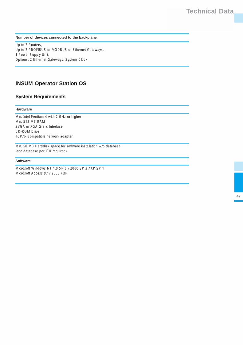
INSUM Operator Station OS
Hardware
Min. Intel Pentium 4 with 2 GHz or higherMin. 512 MB RAMSVGA or XGA Grafic InterfaceCD-ROM DriveTCP/IP compatible network adapter
Min. 50 MB Harddisk space for software installation w/o database.(one database per ICU required)
Software
Microsoft Windows NT 4.0 SP 6 / 2000 SP 3 / XP SP 1Microsoft Access 97 / 2000 / XP
System Requirements
Number of devices connected to the backplane
Up to 2 Routers, Up to 2 PROFIBUS or MODBUS or Ethernet Gateways, 1 Power Supply Unit, Options: 2 Ethernet Gateways, System Clock
48
Standards and Approvals
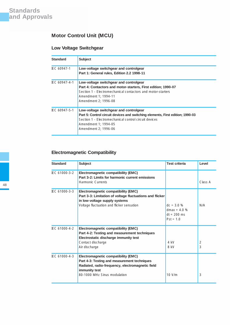
Motor Control Unit (MCU)
Low Voltage Switchgear
Standard Subject
IEC 60947-1 Low-voltage switchgear and controlgearPart 1: General rules, Edition 2.2 1998-11
IEC 60947-4-1 Low-voltage switchgear and controlgearPart 4: Contactors and motor-starters, First edition; 1990-07Section 1 - Electromechanical contactors and motor-startersAmendment 1; 1994-11Amendment 2; 1996-08
IEC 60947-5-1 Low-voltage switchgear and controlgearPart 5: Control circuit devices and switching elements, First edition; 1990-03Section 1 - Electromechanical control circuit devicesAmendment 1; 1994-05Amendment 2; 1996-06
Electromagnetic Compatibility
Standard Subject Test criteria Level
IEC 61000-3-2 Electromagnetic compatibility (EMC)Part 3-2: Limits for harmonic current emissionsHarmonic Currents Class A
IEC 61000-3-3 Electromagnetic compatibility (EMC)Part 3-3: Limitation of voltage fluctuations and flicker in low-voltage supply systems Voltage fluctuation and flicker sensation dc = 3.0 % N/A
dmax = 4.0 %dt = 200 msPst = 1.0
IEC 61000-4-2 Electromagnetic compatibility (EMC)Part 4-2: Testing and measurement techniquesElectrostatic discharge immunity test Contact discharge 4 kV 2Air discharge 8 kV 3
IEC 61000-4-3 Electromagnetic compatibility (EMC)Part 4-3: Testing and measurement techniques Radiated, radio-frequency, electromagnetic field immunity test80-1000 MHz Sinus modulation 10 V/m 3

49
Standards and Approvals
Standard Subject Test criteria Level
IEC 61000-4-4 Electromagnetic compatibility (EMC)Part 4-3: Testing and measurement techniquesElectrical fast transient/burst immunity testAC input port 4 kV 4AC output port 4 kV 4Communication, PTC and I/O port 2 kV 3
IEC 61000-4-5 Electromagnetic compatibility (EMC)Part 4-5: Testing and measurement techniquesSurge immunity test AC input 4 kV 4Communication, PTC and I/O port 2 kV 3
DIN EN 55022 Information technology equipment - Radio disturbance characteristics - Limits and methods of measurementConducted emissions 150 kHz - 30 MHz Class BRadiated emissions 30 MHz - 1000 MHz Class B
ENV 50204 Radiated electromagnetic field from digital radio telephones immunity test900 MHz, pulse modulated 10 V/m 3
Approvals The Motor Control Unit hardware version -4 and software version 3.x is in accordance with the regulations
for overload protection of explosion-protected motors of the EEx e-type of protection Directive 94/9/EC
(ATEX 100a).
Physikalisch-Technische Bundesanstalt: Certificate PTB 03 ATEX 3033 dated 9th September 2003.
Environmental Conditions
Standard Subject
IEC 60068-2-6 Vibration (sinusoidal)
IEC 60068-2-27 Shock and bump
IEC 60068-2-29 Bump
IEC 60068-2-30 Damp heat, cyclic

50
Standards and Approvals
INSUM Communications Unit (ICU) devices
Electromagnetic Compatibility
Standard Subject Test criteria Level
EN 50081-1 Electromagnetic compatibility (EMC); generic emission standard0.15 - 0.5 MHz: AC mains port *) 66...56/56...46 dBµV B0.5 - 5 MHz : AC mains port *) 56/46 dBµV B5 - 30 MHz: AC mains port*) 60/50 dBµV B30 - 230 MHz: enclosure 30 dBµV/m B230 - 1000 MHz: enclosure 37 dBµV/m B
IEC 61000-4-2 Electromagnetic compatibility (EMC)Part 4-2: Testing and measurement techniquesElectrostatic discharge immunity test Contact discharge (MMI) 4 kV 2Contact discharge (Router, Gateways) 6 kV 3Air discharge (MMI only) 8 kV 3/PC 'B'
IEC 61000-4-3 Electromagnetic compatibility (EMC)Part 4-3: Testing and measurement techniquesRadiated, radio-frequency, electromagnetic field immunity test80 - 1000 MHz, Sinus modulation 10 V/m 3895 - 905 MHz, Pulse modulation 10 V/m 3
IEC 61000-4-4 Electromagnetic compatibility (EMC)Part 4-3: Testing and measurement techniquesElectrical fast transient/burst immunity testAC mains port * ) 4 kV 424 V DC Power Supply lines 2 kV 3Communication Interface 2 kV 4
IEC 61000-4-5 Electromagnetic compatibility (EMC)Part 4-5: Testing and measurement techniquesSurge immunity testAC mains port *): Asymetrical / symetrical 2/1 kV class 324 V DC Power Supply lines: Asymetrical / symetrical 1/0.5 kV class 2Communication Interface 2 kV class 3
IEC 61000-4-6 Electromagnetic compatibility (EMC)Part 4-6: Testing and measurement techniquesImmunity to conducted disturbances, induced by radio-frequency fieldsAC mains port *) 10 V 324 V DC Power Supply lines 10 V 3Communication Interface 10 V 3
* only with INSUM Power Supply Unit 1TGB 302006

51
Standards and Approvals
Standard Subject Test criteria Level
IEC 61000-4-11 Electromagnetic compatibility (EMC)Part 4-11: Testing and measuring techniquesVoltage dips, short interruptions and voltage variationsimmunity testsAC mains port *) Voltage dips 40 % Un 1000 ms PC 'A'
EC 61000-4-29 Electromagnetic compatibility (EMC)Part 4-29: Testing and measurement techniquesVoltage dips, short interruptions and voltage variationson d.c. input power port immunity testsVoltage dips 24 V DC 70 % Un 1000 ms PC 'A'Voltage dips 24 V DC 40 % Un 100 ms PC 'A'Voltage interruption 24 V DC 30 ms PC 'A'
IEC 60255-5 Electrical RelaysPart 5: Insulation coordination for measuring relays and protection equipment Requirements and tests24 V DC Ground plane +/- 0.8 kV 324 V DC Internal bus lines +/- 0.8 kV 3Bus lines Ground plane +/- 0.8 kV 3
* only with power supply unit 1TGB 302006
Environmental Conditions
Standard Subject
IEC 60255-21-1 Vibration (sinusodial)
IEC 60255-21-2 Shock and bump
IEC 60068-2-1 Cold
IEC 60068-2-2 Dry heat
IEC 60068-2-6 Vibration (sinusodial)
IEC 60068-2-30 Damp heat, cyclic

52
Notes

ABB Low Voltage Systemswww.abb.com/mns
die-
bots
chaf
ter.
com
1TG
C
901
007
B02
02
ABB