pushover seismic analysis of quasi-static tested confined masonry buildings through simplified...
TRANSCRIPT
15th International Brick and Block Masonry Conference
Florianópolis Brazil 2012
PUSH O V E R SE ISM I C A N A L YSIS O F Q U ASI-ST A T I C T EST E D C O N F IN E D M ASO NR Y BUI L DIN GS T H R O U G H SI M PL I F I E D M O D E L
M arques, Rui1; Lourenço, Paulo B .2 1 MSc, PhD Student, University of Minho, Department of Civil Engineering, [email protected]
2 PhD, Professor, University of Minho, Department of Civil Engineering, [email protected]
The confined masonry typology has been traditionally used for building, and also selected for the reconstruction of recently earthquake-damaged cities, in developing countries responding to the seismic-economic couple. However, most of the procedures in design codes adopted for these countries are force-based, which appear to be inadequate for loading cases under severe earthquakes, where the response in displacement plays the essential role for ultimate (life preservation) limit state. In this work, a worldwide review is made of the experimental response of confined masonry buildings, from which a first storey, shear-dominated, mechanism is mostly identified. Then, two full-scale confined masonry structures with regular and irregular plan configurations, quasi-static tested, are analysed under push-over loading of simplified models of the buildings. The idealized models are based on the use of frame and discrete spring elements, allowing to consider the interaction between the masonry panel and the r.c. confining elements. A comparison between the results of tests and the analytical predictions is made, particularly concerning the base shear-displacement response and the damage patterns. The accuracy of the predictions is very satisfactory, allowing to capture the base shear-displacement response envelope and the general damage trend on the buildings, and thus making the method able for performance-based design procedures.
Keywords: Confined masonry, building response, quasi-static tests, pushover analysis, simplified model IN T R O DU C T I O N The confined masonry (CM) is a construction typology that was first introduced reacting locally to destructive earthquakes in Italy and Chile (1908 Messina and 1929 Talca earthquakes, respectively), which completely destroyed the unreinforced masonry (URM) buildings (Figure 1a). According to Brzev (2007), the CM buildings showed a good performance when subjected to the 1939 Chillan earthquake (Figure 1b), this probably being the main reason for the great dissemination of this construction technique initially in Chile, and after to all Latino-America. This typology was first used in the building of low-rise family dwellings (up to 2 storeys), and more latter as an economical solution in the urban expansion with 3-4 storey buildings (Moroni et al., 2002). The construction with CM has registered a widespread application to all Continents, in countries with medium-to-high seismicity such as Slovenia, India, New Zealand, Japan and Canada. Effectively, the large window of the world was opened to this earthquake-resistant construction typology (Figure 2), given its constructive and economic advantages.

15th International Brick and Block Masonry Conference
Florianópolis Brazil 2012
F igure 1: Post-quake scenarios in Talca (UR M buildings) and Chillan (C M buildings)
F igure 2: World map of seismic hazard
However, even if early some technical instructions were introduced for the CM construction, mainly in a prescriptive way, design rules for seismic resistance were not specified or applied, which aspect has been denoted by the insufficient seismic performance of CM buildings to more recent earthquakes, such as exemplified in Figure 3. Effectively, this construction typology started only to be a matter of study in the structural engineering field in the end of
reinforcement are sufficient to avoid propagation of the diagonal crack into the corner and to
F igure 3: Damage in C M building due to the 2010 Chile earthquake (B rzev et al., 2010)

15th International Brick and Block Masonry Conference
Florianópolis Brazil 2012
Conceptually, the CM system bases in the embracing of the masonry panels with r.c. elements, such as in the r.c. (RC) system, but with the difference that in the CM the r.c. confining elements are cast after the masonry assemblage. By this reason, contrarily to the RC typology where a infill masonry is constructed after the concrete hardening, in the case of the CM the posterior cast of the r.c. confining elements induces a post-tension on the masonry panel, as presented in Figure 4. By this reason, the CM wall responds as a whole until large deformation levels, allowing an improved strength and ductility, as concluded from the experimental study by Gouveia and Lourenço (2007) with main results in Figure 5.
F igure 4: Illust ration of the C M technique and of the difference between C M and R C
F igure 5: Results of lateral cyclic loading tests on unreinforced and confined masonry
panels (Gouveia and Lourenço, 2007) The experimental response of confined masonry walls under lateral cyclic loading has been widely evaluated in several countries by diverse authors, from which studies different theories and corresponding strength criteria were proposed, as reviewed by Marques and Lourenço (2010). However, a confined masonry building consists of an ensemble of confined masonry wall, for which a complex global behaviour is expected and needing to be considered. Some experimental studies have been carried out on three-dimensional CM structures, which are presented in Figure 6. San Bartolomé (1994) tested 2- and 3-levels CM structures with only two parallel walls in the loading direction, both monotonically and in shaking table (Figure 6a-c). In all cases a first storey collapse by diagonal shear is observed, which is theoretically predictable since this is the typical failure of a single confined wall, and due to the effect of in-plane slenderness since the first level presents the higher bending moment. More interesting is the observation that, for the 2-level CM structure, the registered envelopes of the base shear-first storey displacement response is the same for both monotonic and dynamic tests until the collapse in the dynamic test for an acceleration of 1.4g, corresponding to a 1% first storey drift. The specimen under static loading reaches two times that ductility.
-100
-50
0
50
100
-15 -10 -5 0 5 10 15
Late
ral l
oad
(kN
)
Displacement (mm)
Unreinforced
Confined
15th International Brick and Block Masonry Conference
Florianópolis Brazil 2012
(a) (b) (c)
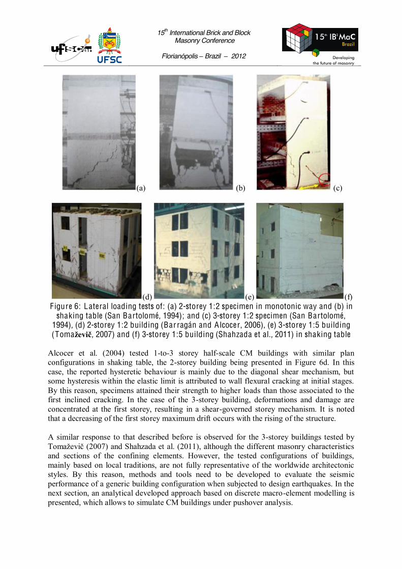
(d) (e) (f) F igure 6: Lateral loading tests of: (a) 2-storey 1:2 specimen in monotonic way and (b) in
shaking table (San Bartolomé, 1994); and (c) 3-storey 1:2 specimen (San Bartolomé, 1994), (d) 2-storey 1:2 building (Barragán and A lcocer, 2006), (e) 3-storey 1:5 building (Toma , 2007) and (f) 3-storey 1:5 building (Shahzada et al., 2011) in shaking table
Alcocer et al. (2004) tested 1-to-3 storey half-scale CM buildings with similar plan configurations in shaking table, the 2-storey building being presented in Figure 6d. In this case, the reported hysteretic behaviour is mainly due to the diagonal shear mechanism, but some hysteresis within the elastic limit is attributed to wall flexural cracking at initial stages. By this reason, specimens attained their strength to higher loads than those associated to the first inclined cracking. In the case of the 3-storey building, deformations and damage are concentrated at the first storey, resulting in a shear-governed storey mechanism. It is noted that a decreasing of the first storey maximum drift occurs with the rising of the structure. A similar response to that described before is observed for the 3-storey buildings tested by
(2007) and Shahzada et al. (2011), although the different masonry characteristics and sections of the confining elements. However, the tested configurations of buildings, mainly based on local traditions, are not fully representative of the worldwide architectonic styles. By this reason, methods and tools need to be developed to evaluate the seismic performance of a generic building configuration when subjected to design earthquakes. In the next section, an analytical developed approach based on discrete macro-element modelling is presented, which allows to simulate CM buildings under pushover analysis.

15th International Brick and Block Masonry Conference
Florianópolis Brazil 2012
M E T H O D O L O G Y F O R SE ISM I C ASSESSM E N T In this work, an approach developed by Caliò et al. (2005) based on the modelling with a discrete element and implemented in the 3DMacro software, is used to model CM structures. The flexural behaviour of the macro-element is simulated by including a set of nonlinear transversal springs between elements, to simulate the stress distribution on the interface section (Figure 7a). By other hand, two diagonal springs connecting the corners of the macro-element are included to simulate the diagonal shear mechanism, as presented in Figure 7b. The above approach allows also, to include linear elements simulating bracing elements that present 2D (beams) or 3D (columns) interaction with the masonry panels, which is the case of the CM walls (Figure 7c). These elements are modelled as nonlinear beam finite elements with concentrated plasticity, as in Figure 7d. Corresponding to the kind of interaction, axial, flexural and axial-flexural hinges are considered according to given NMxMy dominium exemplified in Figure 7e. The modelling of a whole building is made by assembling all CM walls taking as reference dimensions for the mesh generation the opening alignments.
(a) (b)
(c) (d) (e)
F igure 7: Discrete macro-element: (a) interface modelling, (b) failure mechanisms, (c) C M wall model, (d) nonlinear beam element and (e) NM xM y interaction dominium
The nonlinear static (pushover) analysis is the used procedure for evaluation of the seismic response of the buildings, since it allows to capture the inelastic capacity in displacements, which plays the essential role for ultimate limit (life preservation) state. The analysis is made using an incremental-iterative procedure, which allows to predict the base shear-displacement response (capacity curve) and to simulate the damage evolution in the individual elements. The structure is in a first stage submitted to the vertical loading, and then the analysis proceeds with horizontal loading replicating the seismic loading. Then, by using a performance-based methodology (e.g., N2 method (Fajfar and Fischinger, 1988)) the expected
Plastic hinge
node i node j
Mmedium

15th International Brick and Block Masonry Conference
Florianópolis Brazil 2012
displacement demands in design earthquakes are computed by means of a response spectrum analysis of an equivalent s.d.o.f. system, which are afterwards compared with the deformation capacities at given performance levels identified on the computed capacity curve. C ASE ST UDI ES To evaluate the accuracy of the predictions by the 3DMacro method regarding its use in performance-based design, two case studies are presented. The first is a two-level tridimensional CM structure (Figure 8a) tested by Sánchez et al. (1996) at CENAPRED, Mexico, under static lateral cyclic loading according to a height proportional fashion. The structural system consists of CM panels of fired clay bricks with typical r.c. confining elements. A r.c. slab coupled to the beams provide the floor system. The masonry properties obtained from experimental tests were a compressive strength fm = 5.3 MPa, a diagonal shear strength tm = 0.59 MPa, an elastic modulus E = 1495 MPa and a shear modulus G = 911 MPa. The lateral loads were applied through four hydraulic actuators of double action, such as presented in Figure 8b. The gravitational loads were simulated through the application of six actuators anchored on the top slab, maintaining a load in the first storey walls of 0.49 MPa. The first inclined cracks in the masonry occurred in the first storey walls for a base shear of 337 kN and a first storey drift of 0.12%. Then, a concentration of damage in the first storey was observed, where the diagonal cracking was the main pattern (Figure 9a). The penetration of diagonal cracks into the columns occurred for distortions of about 0.4% in the first storey. In the end of the test, these r.c. elements present peeling of the concrete and folding of the longitudinal reinforcement bars, failing by shear and causing the collapse of the model.
(a) (b) (c)
F igure 8: 3D C M structure (a) building view and (b) test layout (Sánchez et al., 1996), and (c) 3DM acro model
The 3DMacro model of the building is presented in Figure 8c, the predictions in terms of ultimate damage, corresponding stresses and loads on elements, and base shear-displacement response appearing in Figure 9. The predicted response of the structure is in general very accurate, namely by identifying the general damage mechanism and by capturing a base shear-1st storey displacement response envelope perfectly adjusted to the experimental response. Figure 9c presents the predicted stress distribution on elements for ultimate state, which denotes a complex interaction between masonry piers and confining elements.

15th International Brick and Block Masonry Conference
Florianópolis Brazil 2012
(a) (b)
(c) (d) F igure 9: Structure response: (a) real and (b) predicted ultimate damage, (c) predicted stresses on elements and (d) experimental versus predicted load-displacement response
A second building tested by Zabala et al. (2004) at CISMID, Peru, which presents structural irregularity as shown in Figure 10a, was also studied. This building represents a typical family house in Peru with 2.5 m storey height and 100 t mass, which was built using handmade clay bricks. A compressive strength fm of 4.65 MPa was obtained from tests, from which a diagonal shear strength tm was estimated as 0.3132fm
1/2 = 0.68 MPa. Elastic modulus E and shear modulus G were respectively predicted as 400fm = 1860 MPa and 0.4E = 744 MPa. Figure 10b presents the test setup, where two actuators on the second floor and one actuator on the first floor were in position to push and pull the building, in order to develop a cyclic loading. The test was carried out under mix control, one actuator on the second floor with displacement control and the others actuators under load control, a load pattern proportional to the building height being induced. It was related that the structure behaves elastically until a 0.0625% inter-storey drift, the cracking on walls starting for 0.125% drift. High degradation was related under 0.5% drift, the maximum deterioration occurring for 1.33% drift.
F igure 10: A rchitectural plan and global view of the tested building (Zabala et al., 2004)
80.44 69.46
56.67 37.85 34.2465.46
71.05 89.67 Bas
e S
hear
Forc
e (k
N)
-500.0
-400.0
-300.0
-200.0
-100.0
0.0
100.0
200.0
300.0
400.0
500.0
-15.0 -12.5 -10.0 -7.5 -5.0 -2.5 0.0 2.5 5.0 7.5 10.0 12.5 15.0B
ase
shea
r fo
rce
(kN
)D isplacement at 1st level (mm)
-400.0
-200.0
0.0
200.0
400.0
-15.0 -10.0 -5.0 0.0 5.0 10.0 15.0Displacement at 1st Level (mm)
---- Test
Prediction
x: diagonal cracking =: flexural cracking

15th International Brick and Block Masonry Conference
Florianópolis Brazil 2012
The geometric and computational models of the building generated in the 3DMacro software are presented in Figure 11, the experimental and predicted crack patterns appearing in Figure 12a-c. Regarding the damage on the main façade of the building, the simulation was capable to predict the confined panels presenting higher degradation, as identified in Figure 12a-b.
F igure 11: G eometric and computational models of the building
(a)
x: diagonal cracking =: flexural cracking (b)
F igure 12: C rack trend of: (a) test for 0.125% and 1% 1st-storey drifts, (b) simulation for 0.125% and ultimate 1st-storey drifts in right- and leftward and (c) at peak base shear in right- and leftward directions; and test hysteresis versus p redicted envelope
Displacement at Roof Level (mm)
Base
She
ar F
orce
(tf)
Prediction
(d) (c)

15th International Brick and Block Masonry Conference
Florianópolis Brazil 2012
Figure 12d presents the experimental hysteretic behavior showing the evolution of stiffness, base shear and roof displacement of the building, which is compared with the capacity envelope obtained from the pushover analysis. The prediction was globally capable to capture the main aspects of the response, even if the displacement capacity in rightward direction was underestimated 30% and the base shear capacity in leftward direction being overestimated 15%, which are however acceptable tolerances given the complexity of the building. C O N C L USI O NS The confined masonry has been used since a century ago, in all Continents, by using very different materials, but a common basic constructive technique. This typology was initially used in the structure of low-height buildings presenting a satisfactory seismic behaviour based mainly on prescriptive design rules. However, since this typology was used in construction of 3-4 storey buildings, a deficient seismic performance was observed due to lack or no-application of engineered design rules. Then, in this work a review was made regarding the worldwide investigation of the seismic behaviour of confined masonry structures, aiming to capture the main aspects of its global response. Experimental response of confined masonry structures denotes mostly a first storey-dominant mechanism, with some elastic hysteresis due to flexural cracks at low-level deformations, a diagonal cracking of the masonry following with propagation into the confinement columns until the collapse of the structure for high deformations. By this reason, a sufficient density of walls needs to be included in the first storey of the building, in mode to avoid a too pronounced mechanism. It is also noted that a sufficient reinforcement of the confinement columns, as identified in the case studies, is requested to avoid early flexural failure. The high displacement capacity of the confined masonry structures claims for the use of performance-based design procedures, allowing to consider the inelastic reserve of the buildings. Then, a method based on discrete element modelling and pushover analysis was applied to two experimental cases of confined masonry structures under quasi-static lateral cyclic loading. The predicted responses were capable to capture the response of the buildings, both in terms of damage and base shear-displacement envelope, the method thus being able to use in performance-based safety verification, for example through the N2 method. A C K N O W L E D G E M E N TS The first author gratefully acknowledges the financial support from the Portuguese Foundation for Science and Technology through the PhD grant SFRH/BD/41221/2007. R E F E R E N C ES Alcocer, S.M., Arias, J.G., Vá
Earthquake Engineering, Vancouver, 2004, Paper No. 2130. Barrágan, R., Alc -scale models of confined masonry
Earthquake Engineering and Seismology, Geneva, 2006, Paper No. 1147. Brzev, S. Earthquake-Resistant Confined Masonry Construction. NICEE, Kanpur, 2007.

15th International Brick and Block Masonry Conference
Florianópolis Brazil 2012
Brzev, S., Astroza, M., Moroni, O. Performance of Confined Masonry Buildings in the February 27, 2010 Chile Earthquake. EERI Report, California, 2010.
ings of the 10th International Conference on Civil, Structural and Environmental Engineering Computing, Rome, 2005, Paper No. 195.
Proceedings of the 9th World Conference on Earthquake Engineering, Vol. 5, Tokyo-Kyoto, 1988, pp 111-116.
ted to cyclic loading: Influence of
Masonry Conference, 2007, Paper No. 042.
Proceed. of the 8th International Masonry Conference, Dresden, Vol. 3, 2010, pp 2193-2202. Meli, R., Zeevaert, W., Esteva, L. Behaviour of Reinforced Masonry under Alternating Loads. Instituto de Ingeniería, UNAM, Report No. 156, 1968.
Conference on Earthquake Engineering, Rome, Vol. 1, 1974, pp 853-862.
Encyclopedia. EERI-IAEE, Housing Report # 7, 2002. San Bartolomé, A. Masonry Construction: Seismic Behaviour and Structural Design. Editorial Fund, Catholic University of Peru, Lima, 1994 (in Spanish).
masonry structure, full-Conference of Structural Engineering, Mérida-Yucatán, Vol. 2, 1996, pp 909-18 (in Spanish).
ble test of -260, 2011, pp 689-693.
3DMacro: Computer program for the three-dimensional seismic analysis of masonry structures, University of Catania and Gruppo Sismica, 2011. Toma -resistant design of masonry structures:
, Canadian Journal of Civil Engeenering, 34, 2007, pp 1403-1412.
masonry Proceedings of the 13th World Conference on Earthquake Engineering, Vancouver, 2004, Paper No. 2885.