project manual douglas macarthur at taney avenue
TRANSCRIPT
Project Manual
DOUGLAS MACARTHUR
AT TANEY AVENUE ALEXANDRIA CITY PUBLIC SCHOOLS
ALEXANDRIA, VIRGINIA
ARCHITECT, MEP, FP & STRUCTURAL ENGINEERS SPRINGFIELD, VIRGINIA
ADTEK ENGINEERS, INC. CIVIL ENGINEER FAIRFAX, VIRGINIA
A/E’s Project # 550502
October 24, 2019 Volume 2 of 2

DOUGLAS MACARTHUR AT TANEY AVENUE ALEXANDRIA CITY PUBLIC SCHOOLS, ALEXANDRIA, VA
Architect’s Project No: 550502
TABLE OF CONTENTS 001100 - 1
TECHNICAL SPECIFICATIONS
VOLUME 1
DIVISION 1 - GENERAL REQUIREMENTS
011000 Summary 012100 Allowances 012500 Substitution Procedures 012501 Substitution Request Form – Before Receipt of Bids 012502 Substitution Request Form – After Receipt of Bids 012600 Contract Modification Procedures 012601 Project Modification Form 012900 Payment Procedures 013100 Project Management and Coordination 013200 Construction Progress Documentation 013300 Submittal Procedures 014000 Quality Requirements 014200 References 015000 Temporary Facilities and Controls 016000 Product Requirements 017300 Execution 017419 Construction Waste Management 017700 Closeout Procedures 017839 Project Record Documents 017900 Demonstration and Training 018119 Indoor Air Quality Requirements
DIVISION 2- EXISTING CONDITIONS
024119 Selective Structure Demolition
DIVISION 3 – CONCRETE
033000 Cast-In-Place Concrete
DIVISION 4 - MASONRY
042000 Unit Masonry
DIVISION 5 – METALS
055000 Metal Fabrications
DOUGLAS MACARTHUR AT TANEY AVENUE ALEXANDRIA CITY PUBLIC SCHOOLS, ALEXANDRIA, VA
Architect’s Project No: 550502
TABLE OF CONTENTS 001100 - 2
DIVISION 6 - WOOD PLASTICS AND COMPOSITES – NOT USED
DIVISION 7 - THERMAL AND MOISTURE PROTECTION
075423 Thermoplastic Polyolefin (TPO) Roofing 076201 Flashing, Sheet Metal and Roofing Accessories 079200 Joint Sealants
DIVISION 8 - OPENINGS
081113 Steel Doors and Frames 081416 Flush Wood Doors 084113 Aluminum Framed Entrances and Storefront 087100 Door Hardware
DIVISION 9 - FINISHES
092216 Cold-Formed Steel Framing – Non-Structural (CFSF-NS) 092900 Gypsum Board 093000 Tiling 095113 Acoustical Panel Ceilings 096513 Resilient Base and Accessories 096519 Resilient Tile Flooring 096566.16 Vinyl Athletic Flooring 096813 Tile Carpeting 099100 Painting
DIVISION 10 - SPECIALTIES
101100 Visual Display Surfaces 101400 Signage 102123 Cubicle Curtains and Track 104416 Fire Extinguishers
DIVISION 11 - EQUIPMENT
116143 Stage Curtains 116623 Gymnasium Equipment
DIVISION 12 - FURNISHINGS
122113 Horizontal Louver Blinds 123216 Manufactured Plastic-Laminate-Faced Casework
DIVISION 13 - SPECIAL CONSTRUCTION
132800 Hazardous and Universal Waste Management 132801 Removal of Asbestos-Containing Materials 132802 Lead Control Procedures
DOUGLAS MACARTHUR AT TANEY AVENUE ALEXANDRIA CITY PUBLIC SCHOOLS, ALEXANDRIA, VA
Architect’s Project No: 550502
TABLE OF CONTENTS 001100 - 3
DIVISION 14 - CONVEYING SYSTEMS – NOT USED
VOLUME 2
DIVISION 21 - FIRE SUPPRESSION
210500 Common Work Results for Fire-Suppression 210533 Heat Tracing for Fire Suppression Piping 211000 Water-Based Fire-Suppression Systems
DIVISION 22 - PLUMBING
220500 Common Work Results for Plumbing 220513 Motors for Plumbing Equipment 220517 Sleeves and Sleeve Seals for Plumbing Piping 220519 Meters and Gages for Plumbing Piping 220523 General-Duty Valves for Plumbing Piping 220529 Hangers and Supports for Plumbing Piping and Equipment 220553 Identification for Plumbing Piping and Equipment 220700 Plumbing Insulation 221113 Facility Natural Gas Piping 221116 Domestic Water Piping 221119 Domestic Water Piping Specialties 221125 Circulating Pumps 223400 Fuel Fired, Domestic-Water Heaters
DIVISION 23 - MECHANICAL
230500 Common Work Results for HVAC
DIVISION 26 - ELECTRICAL
260519 Low-Voltage Electrical Power Conductors and Cables 260529 Hangers and Supports for Electrical Systems 260533 Raceway and Boxes for Electrical Systems 260923 Lighting Control Devices 265119 LED Interior Lighting
DIVISION 27 – COMMUNICATIONS – NOT USED
DIVISIONS 28 - ELECTRONIC SAFETY AND SECURITY
281300 Access Control 281600 Intrusion Detection System 282300 Video Surveillance 283111 Digital, Addressable Fire-Alarm System

DOUGLAS MACARTHUR AT TANEY AVENUE ALEXANDRIA CITY PUBLIC SCHOOLS, ALEXANDRIA, VA
Architect’s Project No: 550502
TABLE OF CONTENTS 001100 - 4
DIVISION 31 – EARTHWORK – NOT USED
DIVISION 32 – EXTERIOR IMPROVEMENTS – NOT USED
DIVISION 33 – UTILITIES – NOT USED
DIVISION 34 – TRANSPORTATION – NOT USED
END OF TABLE OF CONTENTS

DOUGLAS MACARTHUR AT TANEY AVENUE ALEXANDRIA CITY PUBLIC SCHOOLS, ALEXANDRIA, VA
Architect’s Project No: 550502
COMMON WORK RESULTS FOR FIRE-SUPPRESSION 210500 - 1
SECTION 210500 - COMMON WORK RESULTS FOR FIRE-SUPPRESSION
PART 1 - GENERAL
1.1 RELATED DOCUMENTS
A. Provisions of the Contract and of the Contract Documents apply to this Section.
1.2 DEFINITIONS
A. Finished Spaces: Spaces other than mechanical and electrical equipment rooms, furred spaces, pipe chases, unheated spaces immediately below roof, spaces above ceilings, unexcavated spaces, crawlspaces, and tunnels.
B. Exposed, Interior Installations: Exposed to view indoors.
C. Exposed, Exterior Installations: Exposed to view outdoors.
D. Subject to Freezing: Subject to temperatures below 40 degrees F.
E. Concealed, Interior Installations: Concealed from view and protected from physical contact by occupants.
F. Concealed, Exterior Installations: Concealed from view and protected from physical contact by occupants.
G. The following are industry abbreviations for rubber materials:
1. EPDM: Ethylene-propylene-diene terpolymer rubber. 2. NBR: Acrylonitrile-butadiene rubber.
1.3 SUBMITTALS
A. LEED Submittals: Refer to Division 1 Section “Sustainable Design Requirements.”
1.4 QUALITY ASSURANCE
A. Equipment and appliances comprising portions of the mechanical systems regulated by the International Mechanical Code shall be listed and labeled in accordance with the current edition of the Virginia Construction Code.
B. Equipment and appliances comprising portions of the mechanical systems regulated by the International Mechanical Code shall be installed in accordance with the listing, the manufacturer’s installation instructions, and the Virginia Construction Code. Manufacturer’s installation instructions shall be available on the job site for use and inspection.

DOUGLAS MACARTHUR AT TANEY AVENUE ALEXANDRIA CITY PUBLIC SCHOOLS, ALEXANDRIA, VA
Architect’s Project No: 550502
COMMON WORK RESULTS FOR FIRE-SUPPRESSION 210500 - 2
C. Steel Support Welding: Qualify processes and operators according to AWS D1.1, "Structural Welding Code--Steel."
D. Steel Pipe Welding: Qualify processes and operators according to ASME Boiler and Pressure Vessel Code: Section IX, "Welding and Brazing Qualifications."
1. Comply with provisions in ASME B31 Series, "Code for Pressure Fire-suppression piping."
2. Certify that each welder has passed AWS qualification tests for welding processes involved and that certification is current.
E. ASME Compliance: Comply with ASME A13.1, "Scheme for the Identification of Fire-suppression piping Systems," for letter size, length of color field, colors, and viewing angles of identification devices for fire-suppression piping.
F. Electrical Characteristics for Fire-Suppression Equipment: Equipment of higher electrical characteristics may be furnished provided such proposed equipment is approved in writing and connecting electrical services, circuit breakers, and conduit sizes are appropriately modified. If minimum energy ratings or efficiencies are specified, equipment shall comply with requirements.
1.5 DELIVERY, STORAGE, AND HANDLING
A. Deliver pipes and tubes with factory-applied end caps. Maintain end caps through shipping, storage, and handling to prevent pipe end damage and to prevent entrance of dirt, debris, and moisture.
1.6 COORDINATION
A. Arrange for pipe spaces, chases, slots, and openings in building structure during progress of construction, to allow for fire-suppression installations.
B. Coordinate installation of required supporting devices and set sleeves in poured-in-place concrete and other structural components as they are constructed.
C. Coordinate requirements for access panels and doors for fire-suppression items requiring access that are concealed behind finished surfaces. Access panels and doors are specified in Division 08 Section "Access Doors and Frames.
1.7 INTENT OF CONTRACT DOCUMENTS
A. Fire Suppression/Protection drawings are diagrammatic, indicating general locations and arrangements of pipe, and equipment. Not necessarily indicating all offsets, conditions, and appurtenances required to provide clearances for maximum practical accessibility to perform maintenance.

DOUGLAS MACARTHUR AT TANEY AVENUE ALEXANDRIA CITY PUBLIC SCHOOLS, ALEXANDRIA, VA
Architect’s Project No: 550502
COMMON WORK RESULTS FOR FIRE-SUPPRESSION 210500 - 3
B. Coordinate work in order to achieve proper operation and to provide a maintainable installed condition.
C. Notify the Architect’s representative immediately of conditions which do not comply or will not produce this result.
PART 2 - PRODUCTS
2.1 DIELECTRIC FITTINGS
A. Description: Combination fitting of copper alloy and ferrous materials with threaded, solder-joint, plain, or weld-neck end connections that match fire-suppression piping system materials.
B. Insulating Material: Suitable for system fluid, pressure, and temperature.
C. Dielectric Unions: Factory-fabricated, union assembly, for 250-psig minimum working pressure at 180ºF.
D. Dielectric-Flange Kits: Companion-flange assembly for field assembly. Include flanges, full-face- or ring-type neoprene or phenolic gasket, phenolic or polyethylene bolt sleeves, phenolic washers, and steel backing washers.
1. Separate companion flanges and steel bolts and nuts shall have 150- or 300-psig minimum working pressure where required to suit system pressures.
E. Dielectric Couplings: Galvanized-steel coupling with inert and non-corrosive, thermoplastic lining; threaded ends; and 300-psig minimum working pressure at 225ºF.
F. Dielectric Nipples: Electroplated steel nipple with inert and non-corrosive, thermoplastic lining; plain, threaded, or grooved ends; and 300-psig minimum working pressure at 225ºF.
2.2 MECHANICAL SLEEVE SEALS
A. Description: Modular sealing element unit, designed for field assembly, to fill annular space between pipe and sleeve.
1. Available Manufacturers:
a. Advance Products & Systems, Inc. b. Calpico, Inc. c. Metraflex Co. d. Pipeline Seal and Insulator, Inc.
2. Sealing Elements: EPDM interlocking links shaped to fit surface of pipe. Include type and number required for pipe material and size of pipe.
3. Pressure Plates: Plastic. Include two for each sealing element.
DOUGLAS MACARTHUR AT TANEY AVENUE ALEXANDRIA CITY PUBLIC SCHOOLS, ALEXANDRIA, VA
Architect’s Project No: 550502
COMMON WORK RESULTS FOR FIRE-SUPPRESSION 210500 - 4
4. Connecting Bolts and Nuts: Carbon steel with corrosion-resistant coating of length required to secure pressure plates to sealing elements. Include one for each sealing element.
2.3 JOINING MATERIALS
A. Pipe Joint Compound for Threaded Pipe: UL listed.
B. Adhesives applied inside the weatherproofing system shall comply with the South Coast Air Quality Management District (SCAQMD) Rule #1168 VOC limits as required for LEED. VOC limits correspond to an effective date of July 1, 2005 and rule amendment date of January 7, 2005. VOC limits are reprinted in the LEED Reference Guide and are available from the Architect upon request.
C. Sealants and sealant primers applied inside the weatherproofing system shall comply with the South Coast Air Quality Management District (SCAQMD) Rule #1168 VOC limits as required for LEED.
1. Architectural Sealants: 250 g/L or less. 2. Other Sealants: 420 g/L or less. 3. Architectural sealant primers (nonporous): 250 g/L or less. 4. Architectural sealant primers (porous): 775 g/L or less. 5. Other sealant primers: 750 g/L or less.
2.4 SLEEVES
A. Galvanized-Steel Sheet: 0.0239-inch minimum thickness; round tube closed with welded longitudinal joint.
B. Steel Pipe: ASTM A 53, Type E, Grade B, Schedule 40, galvanized, plain ends.
C. Cast Iron: Cast or fabricated "wall pipe" equivalent to ductile-iron pressure pipe, with plain ends and integral waterstop, unless otherwise indicated.
D. Molded PE: Reusable, PE, tapered-cup shaped, and smooth-outer surface with nailing flange for attaching to wooden forms.
2.5 ESCUTCHEONS
A. Description: Manufactured wall and ceiling escutcheons and floor plates, with an ID to closely fit around fire-suppression piping and an OD that completely covers opening.
B. One-Piece, Deep-Pattern Type: Deep-drawn, box-shaped brass with polished chrome-plated finish.
C. One-Piece, Cast-Brass Type: With set screw.

DOUGLAS MACARTHUR AT TANEY AVENUE ALEXANDRIA CITY PUBLIC SCHOOLS, ALEXANDRIA, VA
Architect’s Project No: 550502
COMMON WORK RESULTS FOR FIRE-SUPPRESSION 210500 - 5
1. Finish: Polished chrome-plated and rough brass.
D. Split-Casting, Cast-Brass Type: With concealed hinge and set screw.
1. Finish: Polished chrome-plated and rough brass.
E. One-Piece, Stamped-Steel Type: With set screw or spring clips and chrome-plated finish.
F. Split-Plate, Stamped-Steel Type: With exposed-rivet hinge, set screw or spring clips, and chrome-plated finish.
G. One-Piece, Floor-Plate Type: Cast-iron floor plate.
H. Split-Casting, Floor-Plate Type: Cast brass with concealed hinge and set screw.
2.6 GROUT
A. Description: ASTM C 1107, Grade B, nonshrink and nonmetallic, dry hydraulic-cement grout.
1. Characteristics: Post-hardening, volume-adjusting, nonstaining, noncorrosive, nongaseous, and recommended for interior and exterior applications.
2. Design Mix: 5000-psi, 28-day compressive strength. 3. Packaging: Premixed and factory packaged.
2.7 FIRE-SUPPRESSION PIPING IDENTIFICATION DEVICES
A. Manufactured Pipe Markers, General: Preprinted, color-coded, with lettering indicating service, and showing direction of flow.
1. Colors: Comply with ASME A13.1, unless otherwise indicated. 2. Lettering: Use fire-suppression piping system terms indicated. 3. Pipes with OD, Including Insulation, Less Than 6 Inches: Full-band pipe markers
extending 360 degrees around pipe at each location. 4. Pipes with OD, Including Insulation, 6 Inches and Larger: Either full-band or strip-type
pipe markers at least three times letter height and of length required for label. 5. Arrows: Integral with fire-suppression piping system service lettering to accommodate
both directions; or as separate unit on each pipe marker to indicate direction of flow.
B. Pretensioned Pipe Markers: Precoiled semirigid plastic formed to cover full circumference of pipe and to attach to pipe without adhesive.
C. Self-Adhesive Pipe Markers: Plastic with pressure-sensitive, permanent-type, self-adhesive back.
D. Plastic Tape: Continuously printed, vinyl tape at least 3 mils thick with pressure-sensitive, permanent-type, self-adhesive back.
DOUGLAS MACARTHUR AT TANEY AVENUE ALEXANDRIA CITY PUBLIC SCHOOLS, ALEXANDRIA, VA
Architect’s Project No: 550502
COMMON WORK RESULTS FOR FIRE-SUPPRESSION 210500 - 6
1. Width for Markers on Pipes with OD, Including Insulation, Less Than 6 Inches: 3/4 inch minimum.
2. Width for Markers on Pipes with OD, Including Insulation, 6 Inches or Larger: 1-1/2 inches minimum.
PART 3 - EXECUTION
3.1 FIRE-SUPPRESSION PIPING SYSTEMS - COMMON REQUIREMENTS
A. Install fire-suppression piping according to the following requirements and Division 21 Sections specifying fire-suppression piping systems.
B. Drawing plans, schematics, and diagrams indicate general location and arrangement of fire-suppression piping systems. Indicated locations and arrangements were used to size pipe and calculate friction loss, expansion, pump sizing, and other design considerations. Install fire-suppression piping as indicated unless deviations to layout are approved on Coordination Drawings.
C. Install fire-suppression piping in concealed locations, unless otherwise indicated and except in equipment rooms and service areas.
D. Install fire-suppression piping indicated to be exposed and fire-suppression piping in equipment rooms and service areas at right angles or parallel to building walls. Diagonal runs are prohibited unless specifically indicated otherwise.
E. Install fire-suppression piping above accessible ceilings to allow sufficient space for ceiling panel removal.
F. Install fire-suppression piping to permit valve servicing.
G. Install fire-suppression piping at indicated slopes.
H. Install fire-suppression piping free of sags and bends.
I. Install fittings for changes in direction and branch connections.
J. Install fire-suppression piping to allow application of insulation.
K. Select system components with pressure rating equal to or greater than system operating pressure.
L. Install escutcheons for penetrations of walls, ceilings, and floors according to the following:
1. New Fire-suppression piping:
a. Fire-suppression piping with Fitting or Sleeve Protruding from Wall: One-piece, deep-pattern type.
DOUGLAS MACARTHUR AT TANEY AVENUE ALEXANDRIA CITY PUBLIC SCHOOLS, ALEXANDRIA, VA
Architect’s Project No: 550502
COMMON WORK RESULTS FOR FIRE-SUPPRESSION 210500 - 7
b. Chrome-Plated Fire-suppression piping: One-piece, cast-brass type with polished chrome-plated finish.
c. Insulated Fire-suppression piping: One-piece, stamped-steel type with spring clips.
d. Bare Fire-suppression piping at Wall and Floor Penetrations in Finished Spaces: One-piece, cast-brass type with polished chrome-plated finish.
e. Bare Fire-suppression piping at Ceiling Penetrations in Finished Spaces: One-piece, cast-brass type with polished chrome-plated finish.
f. Bare Fire-suppression piping in Unfinished Service Spaces: One-piece, cast-brass type with rough-brass finish.
g. Bare Fire-suppression piping in Equipment Rooms: One-piece, cast-brass type. h. Bare Fire-suppression piping at Floor Penetrations in Equipment Rooms: One-
piece, floor-plate type.
M. Sleeves are not required for core-drilled holes.
N. Permanent sleeves are not required for holes formed by removable PE sleeves.
O. Install sleeves for pipes passing through concrete and masonry walls, gypsum-board partitions, and concrete floor and roof slabs.
1. Cut sleeves to length for mounting flush with both surfaces.
a. Exception: Extend sleeves installed in floors of mechanical equipment areas or other wet areas 2 inches above finished floor level. Extend cast-iron sleeve fittings below floor slab as required to secure clamping ring if ring is specified.
2. Install sleeves in new walls and slabs as new walls and slabs are constructed.
a. Steel Pipe Sleeves: For pipes smaller than NPS 6. b. Steel Sheet Sleeves: For pipes NPS 6 and larger, penetrating gypsum-board
partitions. c. Stack Sleeve Fittings: For pipes penetrating floors with membrane waterproofing.
Secure flashing between clamping flanges. Install section of cast-iron soil pipe to extend sleeve to 2 inches above finished floor level. Refer to Division 07 Section "Sheet Metal Flashing and Trim" for flashing.
1) Seal space outside of sleeve fittings with grout.
3. Except for underground wall penetrations, seal annular space between sleeve and pipe or pipe insulation, using joint sealants appropriate for size, depth, and location of joint. Refer to Division 07 Section "Joint Sealants" for materials and installation.
P. Aboveground, Exterior-Wall Pipe Penetrations: Seal penetrations using sleeves and mechanical sleeve seals. Select sleeve size to allow for 1-inch annular clear space between pipe and sleeve for installing mechanical sleeve seals.
1. Install steel pipe for sleeves smaller than 6 inches in diameter. 2. Install cast-iron "wall pipes" for sleeves 6 inches and larger in diameter.

DOUGLAS MACARTHUR AT TANEY AVENUE ALEXANDRIA CITY PUBLIC SCHOOLS, ALEXANDRIA, VA
Architect’s Project No: 550502
COMMON WORK RESULTS FOR FIRE-SUPPRESSION 210500 - 8
3. Mechanical Sleeve Seal Installation: Select type and number of sealing elements required for pipe material and size. Position pipe in center of sleeve. Assemble mechanical sleeve seals and install in annular space between pipe and sleeve. Tighten bolts against pressure plates that cause sealing elements to expand and make watertight seal.
Q. Underground, Exterior-Wall Pipe Penetrations: Install cast-iron "wall pipes" for sleeves. Seal pipe penetrations using mechanical sleeve seals. Select sleeve size to allow for 1-inch annular clear space between pipe and sleeve for installing mechanical sleeve seals.
1. Mechanical Sleeve Seal Installation: Select type and number of sealing elements required for pipe material and size. Position pipe in center of sleeve. Assemble mechanical sleeve seals and install in annular space between pipe and sleeve. Tighten bolts against pressure plates that cause sealing elements to expand and make watertight seal.
R. Fire-Barrier Penetrations: Maintain indicated fire rating of walls, partitions, ceilings, and floors at pipe penetrations. Seal pipe penetrations with firestop materials. Refer to Division 07 Section "Penetration Firestopping" for materials.
S. Verify final equipment locations for roughing-in.
T. Refer to equipment specifications in other Sections of these Specifications for roughing-in requirements.
3.2 FIRE-SUPPRESSION PIPING JOINT CONSTRUCTION
A. Join pipe and fittings according to the following requirements and Division 21 Sections specifying fire-suppression piping systems.
B. Ream ends of pipes and tubes and remove burrs. Bevel plain ends of steel pipe.
C. Remove scale, slag, dirt, and debris from inside and outside of pipe and fittings before assembly.
D. Soldered Joints: Apply ASTM B 813, water-flushable flux, unless otherwise indicated, to tube end. Construct joints according to ASTM B 828 or CDA's "Copper Tube Handbook," using lead-free solder alloy complying with ASTM B 32.
E. Brazed Joints: Construct joints according to AWS's "Brazing Handbook," "Pipe and Tube" Chapter, using copper-phosphorus brazing filler metal complying with AWS A5.8.
F. Threaded Joints: Thread pipe with tapered pipe threads according to ASME B1.20.1. Cut threads full and clean using sharp dies. Ream threaded pipe ends to remove burrs and restore full ID. Join pipe fittings and valves as follows:
1. Apply appropriate tape or pipe joint compound to external pipe threads unless dry seal threading is specified.
DOUGLAS MACARTHUR AT TANEY AVENUE ALEXANDRIA CITY PUBLIC SCHOOLS, ALEXANDRIA, VA
Architect’s Project No: 550502
COMMON WORK RESULTS FOR FIRE-SUPPRESSION 210500 - 9
2. Damaged Threads: Do not use pipe or pipe fittings with threads that are corroded or damaged. Do not use pipe sections that have cracked or open welds.
G. Welded Joints: Construct joints according to AWS D10.12, using qualified processes and welding operators according to Part 1 "Quality Assurance" Article.
H. Flanged Joints: Select appropriate gasket material, size, type, and thickness for service application. Install gasket concentrically positioned. Use suitable lubricants on bolt threads.
3.3 CONCRETE BASES
A. Concrete Bases: Anchor equipment to concrete base according to equipment manufacturer's written instructions and according to seismic codes at Project.
1. Construct concrete bases of dimensions indicated, but not less than 4 inches larger in both directions than supported unit.
2. Install dowel rods to connect concrete base to concrete floor. Unless otherwise indicated, install dowel rods on 18-inch centers around the full perimeter of the base.
3. Install epoxy-coated anchor bolts for supported equipment that extend through concrete base, and anchor into structural concrete floor.
4. Place and secure anchorage devices. Use supported equipment manufacturer's setting drawings, templates, diagrams, instructions, and directions furnished with items to be embedded.
5. Install anchor bolts to elevations required for proper attachment to supported equipment. 6. Install anchor bolts according to anchor-bolt manufacturer's written instructions. 7. Use 3000-psi, 28-day compressive-strength concrete and reinforcement as specified in
Division 03 Section "Cast-in-Place Concrete."
3.4 ERECTION OF METAL SUPPORTS AND ANCHORAGES
A. Refer to Division 05 Section "Metal Fabrications" for structural steel.
B. Cut, fit, and place miscellaneous metal supports accurately in location, alignment, and elevation to support and anchor fire-suppression materials and equipment.
C. Field Welding: Comply with AWS D1.1.
3.5 FIRE-SUPPRESSION PIPING IDENTIFICATION
A. Install manufactured pipe markers indicating service on each fire-suppression piping system. Install with flow indication arrows showing direction of flow.
1. Pipes with OD, Including Insulation, Less Than 6 Inches: Pretensioned pipe markers sized to ensure a tight fit. Or: Self-adhesive pipe markers. Use color-coded, self-adhesive plastic tape, 1-1/2 inches wide, lapped at least 1-1/2 inches at both ends of pipe marker, and covering full circumference of pipe.

DOUGLAS MACARTHUR AT TANEY AVENUE ALEXANDRIA CITY PUBLIC SCHOOLS, ALEXANDRIA, VA
Architect’s Project No: 550502
COMMON WORK RESULTS FOR FIRE-SUPPRESSION 210500 - 10
2. Pipes with OD, Including Insulation, 6 Inches and Larger: Shaped pipe markers. Use size to match pipe and secure with fasteners. Or: Self-adhesive pipe markers. Use color-coded, self-adhesive plastic tape, at least 1-1/2 inches wide, lapped at least 3 inches at both ends of pipe marker, and covering full circumference of pipe.
B. Stenciled Pipe Marker Option: Stenciled markers may be provided instead of manufactured pipe markers, at Installer's option. Install stenciled pipe markers with painted, color-coded bands or rectangles complying with ASME A13.1 on each fire-suppression piping system.
1. Identification Paint: Use for contrasting background. 2. Stencil Paint: Use for pipe marking. 3. Paints and coatings applied inside the weatherproofing system shall comply with the
following: a. Architectural paints, coatings, and primers shall not exceed the VOC content limits
established in Green Seal Standard GS-11, Paints, First Edition, May 20, 1993. VOC limits are printed in the LEED Reference Guide and are available from the Architect upon request.
C. Locate pipe markers and color bands where fire-suppression piping is exposed in finished spaces; machine rooms; accessible maintenance spaces such as shafts, tunnels, and plenums; and exterior nonconcealed locations as follows:
1. Near each valve and control device. 2. Near penetrations through walls, floors, ceilings, and nonaccessible enclosures. 3. At access doors, manholes, and similar access points that permit view of concealed fire-
suppression piping. 4. Near major equipment items and other points of origination and termination. 5. Spaced at maximum intervals of 50 feet along each run. Reduce intervals to 25 feet in
areas of congested fire-suppression piping and equipment. 6. On fire-suppression piping above removable acoustical ceilings.
3.6 GROUTING
A. Mix and install grout for fire suppression equipment base bearing surfaces, pump and other equipment base plates, and anchors.
B. Clean surfaces that will come into contact with grout.
C. Provide forms as required for placement of grout.
D. Avoid air entrapment during placement of grout.
E. Place grout, completely filling equipment bases.
F. Place grout on concrete bases and provide smooth bearing surface for equipment.
G. Place grout around anchors.
H. Cure placed grout.
DOUGLAS MACARTHUR AT TANEY AVENUE ALEXANDRIA CITY PUBLIC SCHOOLS, ALEXANDRIA, VA
Architect’s Project No: 550502
COMMON WORK RESULTS FOR FIRE-SUPPRESSION 210500 - 11
3.7 EXCAVATION AND BACKFILL
A. Excavation and backfill shall be as indicated in Division 1 specifications and on the drawings. If excavation and backfill is not otherwise indicated the following shall apply: 1. Excavate trenches to indicated gradients, lines, depths, and elevations.
a. Beyond the building perimeter, excavate trenches to allow installation of top of pipe below frost line.
2. Excavate trenches to uniform widths to provide twelve inches clear on each side of pipe. Excavate trench walls vertically from trench bottom.
3. Trench Bottoms: Excavate trench bottoms to provide flat surface. Place and compact six inches of sand. Excavate and shape sand to provide uniform bearing and support of pipes. Shape sand to provide continuous support for bells, joints, fittings, and barrels of pipes. Sand shall be free of projecting stones and sharp objects.
4. Backfill and hand tamp to 95% proctor to six inches above the top of the pipe. 5. Backfill and machine tamp the remainder of the trench to 95% proctor in twelve inch
lifts.
END OF SECTION 210500

DOUGLAS MACARTHUR AT TANEY AVENUE ALEXANDRIA CITY PUBLIC SCHOOLS, ALEXANDRIA, VA
Architect’s Project No: 550502
HEAT TRACING FOR FIRE-SUPPRESSION PIPING 210533 - 1
SECTION 210533 - HEAT TRACING FOR FIRE-SUPPRESSION PIPING
PART 1 - GENERAL
1.1 RELATED DOCUMENTS
A. Provisions of the Contract and of the Contract Documents apply to this Section.
1.2 SUBMITTALS
A. Product Data: Include rated capacities, operating characteristics, furnished specialties, and accessories for each type of product indicated.
1. Schedule heating capacity, length of cable, spacing, and electrical power requirement for each electric heating cable required.
B. Shop Drawings: For electric heating cable. Include plans, sections, details, and attachments to other work.
1. Wiring Diagrams: Power, signal, and control wiring.
C. Operation and Maintenance Data: For electric heating cable controls to include in operation and maintenance manuals.
D. Warranty: Special warranty specified in this Section.
1.3 QUALITY ASSURANCE
A. Electrical Components, Devices, and Accessories: Listed and labeled as defined in NFPA 70, Article 100, by a testing agency acceptable to authorities having jurisdiction, and marked for intended use.
1.4 WARRANTY
A. Special Warranty: Manufacturer's standard form in which manufacturer agrees to repair or replace electric heating cable that fails in materials or workmanship within specified warranty period.
1. Warranty Period: 10 years from date of Substantial Completion.
DOUGLAS MACARTHUR AT TANEY AVENUE ALEXANDRIA CITY PUBLIC SCHOOLS, ALEXANDRIA, VA
Architect’s Project No: 550502
HEAT TRACING FOR FIRE-SUPPRESSION PIPING 210533 - 2
PART 2 - PRODUCTS
2.1 SELF-REGULATING, PARALLEL-RESISTANCE HEATING CABLES
A. Basis-of-Design Product: Subject to compliance with requirements, provide the product indicated on Drawings or a comparable product by one of the following:
1. Chromalox, Inc.; Wiegard Industrial Division; Emerson Electric Company. 2. Delta-Therm Corp. 3. Raychem; a division of Tyco Thermal Controls. 4. Thermon Manufacturing Co.
B. Heating Element: Pair of parallel No. 16 AWG, nickel-coated copper bus wires embedded in a self-regulating crosslinked conductive polymeric core, which varies heat output in response to temperature along its length. Terminate with waterproof, factory-assembled non-heating leads with connectors at one end, and seal the opposite end watertight. Cable shall be capable of crossing over itself once without overheating.
C. Electrical Insulating Jacket: Flame-retardant polyolefin.
D. Maximum Operating Temperature (Power On): As scheduled. If not scheduled 120 degrees F.
E. Maximum Exposure Temperature (Power On and Off): 185 deg F.
F. Capacities and Characteristics: As scheduled. If not scheduled 3 watts per linear foot at 115V, 1PH, 60HZ, to maintain 120 degrees F.
2.2 CONTROLS
A. Pipe-Mounting Thermostats for Freeze Protection:
1. Remote bulb unit with adjustable temperature range from 30 to 50 deg F. 2. Snap action; open-on-rise, single-pole switch with minimum current rating adequate for
connected cable. 3. Remote bulb on capillary, resistance temperature device, or thermistor for directly
sensing pipe-wall temperature. 4. Corrosion-resistant, waterproof control enclosure.
2.3 ACCESSORIES
A. Cable Installation Accessories: Fiberglass tape, heat-conductive putty, cable ties, silicone end seals and splice kits, and installation clips all furnished by heat tracing manufacturer, or as recommended in writing by heat tracing manufacturer.
B. Warning Tape: Continuously printed "Electrical Tracing"; vinyl, at least 3 mils thick, and with pressure-sensitive, permanent, waterproof, self-adhesive back.

DOUGLAS MACARTHUR AT TANEY AVENUE ALEXANDRIA CITY PUBLIC SCHOOLS, ALEXANDRIA, VA
Architect’s Project No: 550502
HEAT TRACING FOR FIRE-SUPPRESSION PIPING 210533 - 3
1. Width for Markers on Pipes with OD, Including Insulation, Less Than 6 Inches: 3/4 inch minimum.
2. Width for Markers on Pipes with OD, Including Insulation, 6 Inches or Larger: 1-1/2 inches minimum.
PART 3 - EXECUTION
3.1 EXAMINATION
A. Examine surfaces and substrates to receive electric heating cables for compliance with requirements for installation tolerances and other conditions affecting performance.
1. Ensure surfaces and pipes in contact with electric heating cables are free of burrs and sharp protrusions.
2. Proceed with installation only after unsatisfactory conditions have been corrected.
3.2 APPLICATIONS
3.3 Install electric heating cable: Self-regulating, parallel-resistance heating cable.
3.4 INSTALLATION
A. Install electric heating cable across expansion, construction, and control joints according to manufacturer's written recommendations using cable protection conduit and slack cable to allow movement without damage to cable.
B. Electric Heating Cable Installation for Freeze Protection for Piping:
1. Install electric heating cables after piping has been tested and before insulation is installed.
2. Install electric heating cables according to IEEE 515.1. 3. Install insulation over piping with electric cables according to Division 22 Section
"Plumbing Insulation." 4. Install warning tape on piping insulation where piping is equipped with electric heating
cables.
C. Set field-adjustable switches and circuit-breaker trip ranges.
D. Protect installed heating cables, including non-heating leads, from damage.
3.5 CONNECTIONS
A. Ground equipment according to Division 26 Section "Grounding and Bonding for Electrical Systems."

DOUGLAS MACARTHUR AT TANEY AVENUE ALEXANDRIA CITY PUBLIC SCHOOLS, ALEXANDRIA, VA
Architect’s Project No: 550502
HEAT TRACING FOR FIRE-SUPPRESSION PIPING 210533 - 4
B. Connect wiring according to Division 26 Section "Low-Voltage Electrical Power Conductors and Cables."
3.6 FIELD QUALITY CONTROL
A. Testing: Perform tests after cable installation but before application of coverings such as insulation, wall or ceiling construction, or concrete.
1. Test cables for electrical continuity and insulation integrity before energizing. 2. Test cables to verify rating and power input. Energize and measure voltage and current
simultaneously. Record results. 3. Repeat tests for continuity, insulation resistance, and input power after applying thermal
insulation on pipe-mounting cables. Record results.
B. Remove and replace malfunctioning heat tracing and retest as specified above.
END OF SECTION 210533

DOUGLAS MACARTHUR SWING SPACE ALEXANDRIA CITY PUBLIC SCHOOLS, ALEXANDRIA, VA
Architect’s Project No: 550502
WATER-BASED FIRE-SUPPRESSION SYSTEMS 211000 - 1
SECTION 211000 - WATER-BASED FIRE-SUPPRESSION SYSTEMS
PART 1 - GENERAL
1.1 RELATED DOCUMENTS
A. Provisions of the Contract and of the Contract Documents apply to this Section.
1.2 SUMMARY
A. Description of Work:
1. The work includes designing and providing an automatic fire extinguishing system ofrequired hazard for building occupancy to afford complete fire protection coveragethroughout. Where required the work shall include complete standpipe systems Thedesign, equipment, materials, installation and workmanship shall be in strict accordancewith the Owners insurance underwriters requirements, the Virginia Construction Code,and the required and advisory provisions of NFPA.
2. Each system shall include materials, accessories and equipment necessary to provide eachsystem complete and ready for use.
3. The design of each system shall give full consideration to blind spaces, piping, electricalequipment, ductwork, and all other construction and equipment to afford completecoverage.
4. Devices and equipment for fire protection service shall be of an approved make and typelisted by the Underwriters' Laboratories, Inc., or approved by the Factory Mutual System.
5. In the publications referred to herein, the advisory provisions shall be considered to bemandatory, as though the word "shall" had been substituted for "should" wherever itappears.
6. Reference to the "authority having jurisdiction" shall be interpreted to mean the LocalFire Marshal.
7. Calculations shall include delivering water from the point of the fire hydrant flow testthrough the site piping.
8. Consideration shall be given to all unheated areas such as attics, utility rooms, loadingdocks, outdoor storage spaces with canopies, etc., to provide freeze protection inaccordance with NFPA 13. This shall include the installation of dry sprinklers, anti-freeze, and dry-pipe sprinkler systems where necessary.

DOUGLAS MACARTHUR SWING SPACE ALEXANDRIA CITY PUBLIC SCHOOLS, ALEXANDRIA, VA
Architect’s Project No: 550502
WATER-BASED FIRE-SUPPRESSION SYSTEMS 211000 - 2
1.3 DEFINITIONS
A. CR: Chlorosulfonated polyethylene synthetic rubber.
B. High-Pressure Piping System: Fire-suppression piping system designed to operate at workingpressure higher than standard 175 psig.
C. PE: Polyethylene plastic.
D. Email: for the purposes of this section email shall be considered “in writing”
1.4 SYSTEM DESCRIPTIONS
A. Wet-Pipe Sprinkler System: Automatic sprinklers are attached to piping containing water andthat is connected to water supply. Water discharges immediately from sprinklers when they areopened. Sprinklers open when heat melts fusible link or destroys frangible device.
1.5 PERFORMANCE REQUIREMENTS
A. Component Working Pressure: Listed for at least 175 psig.
B. Design shall be approved by authorities having jurisdiction.
C. Fire-suppression sprinkler system design shall include the following:
1. Margin of Safety for Available Water Flow and Pressure: 10 percent, including lossesthrough water-service piping, valves, and backflow preventers.
2. Sprinkler Occupancy Hazard Classifications shall be as indicated on the drawings. If notindicated comply with NFPA 13.
3. Maximum Protection Area per Sprinkler shall be in accordance with its UL listing.
1.6 SUBMITTALS
A. Product Data: For the following:
1. Piping materials, including flexible connections, and sprinkler specialty fittings.2. Pipe hangers and supports.3. Valves, including listed fire-protection valves, unlisted general-duty valves, specialty
valves and trim.4. Sprinklers, escutcheons, and guards. Include sprinkler flow characteristics, mounting,
finish, and other pertinent data.5. Hose connections, including size, type, and finish.6. Alarm devices, including electrical data.
B. Fire-hydrant flow test report.
DOUGLAS MACARTHUR SWING SPACE ALEXANDRIA CITY PUBLIC SCHOOLS, ALEXANDRIA, VA
Architect’s Project No: 550502
WATER-BASED FIRE-SUPPRESSION SYSTEMS 211000 - 3
C. Approved Sprinkler Piping Shop Drawings: Working plans, prepared according to NFPA 13,that have been approved by authorities having jurisdiction, including hydraulic calculations.Diagram power, signal, and control wiring.1. Include shop drawings indicating location of all sprinkler heads and all other construction
that penetrates ceilings, including light fixtures, HVAC equipment, speakers, fire alarmdevices, partition assemblies, etc.
D. Welding certificates.
E. Operation and Maintenance Data to include in emergency, operation, and maintenance manuals.
1.7 CLOSEOUT SUBMITTALS
A. Field Test Reports and Certificates: Indicate and interpret test results for compliance withperformance requirements and as described in NFPA 13 and NFPA 14. Include "Contractor'sMaterial and Test Certificate for Aboveground Piping" and "Contractor's Material and TestCertificate for Underground Piping."
1.8 QUALITY ASSURANCE
A. Installer Qualifications:
1. Installer's responsibilities include designing, fabricating, and installing fire-suppressionsystems and providing professional engineering services needed to assume engineeringresponsibility. System design shall be by a professional engineer registered in the state ofVirginia or by a NICET Level III or Level IV certified technician in the field of Water-Based Systems Layout.
B. Flow test:
1. Bid shall be based on the indicated fire-hydrant flow and pressure.
2. Design calculations shall be based on the results of a confirming fire-hydrant flow testperformed or caused to be performed by the contractor.
C. Welding: Qualify processes and operators according to ASME Boiler and Pressure VesselCode: Section IX.
D. NFPA Standards: Fire-suppression-system equipment, specialties, accessories, installation, andtesting shall comply with the following:
1. NFPA 13: "Installation of Sprinkler Systems" 2010 edition.2. NFPA 14: "Installation of Standpipe and Hose Systems" 2010 edition.
1.9 COORDINATION
A. Relocate piping to clear the path of ductwork.

DOUGLAS MACARTHUR SWING SPACE ALEXANDRIA CITY PUBLIC SCHOOLS, ALEXANDRIA, VA
Architect’s Project No: 550502
WATER-BASED FIRE-SUPPRESSION SYSTEMS 211000 - 4
B. Relocate piping to clear the path of conduit.
C. Relocate piping to clear the path of cable tray.
D. Coordinate layout and installation of sprinklers with other construction that penetrates ceilings,including light fixtures, HVAC equipment, and partition assemblies.
1.10 SPRINKLER CABINET(S) AND SPARE SPRINKLERS
A. Provide finished, wall-mounted, steel sprinkler cabinet with hinged cover.
B. Provide space for minimum of six spare sprinklers and sprinkler wrench.
C. Provide minimum of six spare sprinklers and sprinkler wrench in cabinet.
D. Provide number of sprinklers required by NFPA 13.
E. Provide separate cabinet with sprinklers and wrench for each type of sprinkler on Project.
F. Provide products packaged with protective covering for storage. Identify contents with label.
PART 2 - PRODUCTS
2.1 DUCTILE-IRON PIPE AND FITTINGS
A. Mechanical-Joint, Ductile-Iron Pipe: AWWA C151, with mechanical-joint bell end and plainend.
1. Mechanical-Joint, Ductile-Iron Fittings AWWA C110, ductile- or gray-iron standardpattern or AWWA C153, ductile-iron compact pattern.
2. Glands, Gaskets, and Bolts: AWWA C111, ductile- or gray-iron gland, rubber gasket,and steel bolts and nuts.
B. Push-on-Joint, Ductile-Iron Pipe: AWWA C151, with push-on-joint bell end and plain end.
1. Push-on-Joint, Ductile-Iron Fittings AWWA C110, ductile- or gray-iron standard patternor AWWA C153, ductile-iron compact pattern.
2. Gaskets: AWWA C111, rubber.
C. Grooved-End, Ductile-Iron Pipe: AWWA C151, with factory formed, radius-cut-grooved endsaccording to AWWA C606.
1. Grooved-Joint Piping Systems:
a. Available Manufacturers:
1) Victaulic Co. of America.
b. Grooved-End Fittings: ASTM A 536, ductile-iron casting with OD matchingductile-iron-pipe OD.
DOUGLAS MACARTHUR SWING SPACE ALEXANDRIA CITY PUBLIC SCHOOLS, ALEXANDRIA, VA
Architect’s Project No: 550502
WATER-BASED FIRE-SUPPRESSION SYSTEMS 211000 - 5
c. Grooved-End-Pipe Couplings: AWWA C606, gasketed fitting matching ductile-iron-pipe OD. Include ductile-iron housing with keys matching ductile-iron-pipeand fitting grooves, prelubricated rubber gasket with center leg, and steel bolts andnuts.
d. Grooved-End-Pipe Transition Coupling: UL 213 and AWWA C606, gasketedfitting with end matching ductile-iron-pipe OD and end matching steel-pipe OD.Include ductile-iron housing with key matching ductile-iron-pipe groove and keymatching steel-pipe groove, prelubricated rubber gasket listed for use withhousing, and steel bolts and nuts.
2.2 STEEL PIPE AND FITTINGS
A. Threaded-End, Schedule 40 Steel Pipe: ASTM A 53/A 53M, ASTM A 135, or ASTM A 795,hot-dip galvanized where indicated and with factory- or shop-formed threaded ends.
1. Cast-Iron Threaded Flanges: ASME B16.1.2. Malleable-Iron Threaded Fittings: ASME B16.3.3. Gray-Iron Threaded Fittings: ASME B16.4.4. Steel Threaded Pipe Nipples: ASTM A 733, made of ASTM A 53/A 53M or
ASTM A 106, Schedule 40, seamless steel pipe. Include ends matching joining method.5. Steel Threaded Couplings: ASTM A 865.
B. Plain-End, Schedule 40 Steel Pipe: ASTM A 53/A 53M, ASTM A 135, or ASTM A 795 hot-dip galvanized where indicated.
1. Steel Welding Fittings: ASTM A 234/A 234M, and ASME B16.9 or ASME B16.11.2. Steel Flanges and Flanged Fittings: ASME B16.5.
C. Grooved-End, Schedule 40 Steel Pipe: ASTM A 53/A 53M, ASTM A 135, or ASTM A 795,hot-dip galvanized where indicated and with factory- or field-formed, square-cut- or roll-grooved ends.
1. Grooved-Joint Piping Systems:
a. Available Manufacturers:
1) Anvil International, Inc.2) Central Sprinkler Corp.3) Ductilic, Inc.4) JDH Pacific, Inc.5) National Fittings, Inc.6) Shurjoint Piping Products, Inc.7) Southwestern Pipe, Inc.8) Star Pipe Products; Star Fittings Div.9) Victaulic Co. of America.10) Ward Manufacturing.
b. Grooved-End Fittings: UL-listed, ASTM A 536, ductile-iron casting with ODmatching steel-pipe OD.
DOUGLAS MACARTHUR SWING SPACE ALEXANDRIA CITY PUBLIC SCHOOLS, ALEXANDRIA, VA
Architect’s Project No: 550502
WATER-BASED FIRE-SUPPRESSION SYSTEMS 211000 - 6
c. Grooved-End-Pipe Couplings: UL 213 and AWWA C606, rigid pattern, unlessotherwise indicated; gasketed fitting matching steel-pipe OD. Include ductile-ironhousing with keys matching steel-pipe and fitting grooves, prelubricated rubbergasket listed for use with housing, and steel bolts and nuts.
D. Grooved-End, Schedule 10 Steel Pipe: Schedule 10 in NPS 2-1/2 to NPS 5; and NFPA 13-specified wall thickness in NPS 6 to NPS 10; with factory- or field-formed, roll-grooved ends.
1. Grooved-Joint Piping Systems:
a. Manufacturers:1) Central Sprinkler Corp.2) Victaulic Co. of America.3) Ward Manufacturing.
b. Grooved-End Fittings: UL-listed, ASTM A 536, ductile-iron casting with ODmatching steel-pipe OD.
c. Grooved-End-Pipe Couplings: UL 213 and AWWA C606, rigid pattern, unlessotherwise indicated; gasketed fitting matching steel-pipe OD. Include ductile-ironhousing with keys matching steel-pipe and fitting grooves, prelubricated rubbergasket listed for use with housing, and steel bolts and nuts.
2.3 FLEXIBLE SPINKLER HOSE FITTINGS
A. Available Manufacturers:1. FlexHead Industries, Inc.2. Flex-Hose Co., Inc.3. Victaulic Co. of America - VicFlex4. Metraflex, Inc.
B. Standard: UL 2443 and FM 1637.
C. Type: Fully stainless steel braided flexible hose for connection to sprinkler, and with one-pieceopen-gate bracket for connection to ceiling grid.1. The bracket shall allow installation before the ceiling tile is in place.
D. Bend radius to 2 inch for proper installation in confined spaces.
E. Pressure Rating: 175 psig minimum.
F. Size: Same as connected piping for sprinkler.
2.4 CORROSION-PROTECTIVE ENCASEMENT FOR PIPING
A. Encasement for Underground Metal Piping: ASTM A 674 or AWWA C105, PE film, 0.008-inch minimum thickness, tube or sheet.

DOUGLAS MACARTHUR SWING SPACE ALEXANDRIA CITY PUBLIC SCHOOLS, ALEXANDRIA, VA
Architect’s Project No: 550502
WATER-BASED FIRE-SUPPRESSION SYSTEMS 211000 - 7
2.5 SPRINKLER SPECIALTY FITTINGS
A. Sprinkler specialty fittings shall be UL listed or FMG approved, with 175-psig minimumworking-pressure rating, and made of materials compatible with piping. Sprinkler specialtyfittings shall have
B. Outlet Specialty Fittings:
1. Available Manufacturers:a. Central Sprinkler Corp.b. Victaulic Co. of America.c. Ward Manufacturing.
2. Mechanical-T and -Cross Fittings: UL 213, ductile-iron housing with gaskets, bolts andnuts, and grooved outlets.
3. Snap-On and Strapless Outlet Fittings: UL 213, ductile-iron housing or casting withgasket and threaded or grooved or grooved outlet.
C. Sprinkler Drain and Alarm Test Fittings: Cast- or ductile-iron body; with threaded, grooved orlocking-lug inlet and outlet, test valve, and orifice and sight glass.
1. Available Manufacturers:
a. Central Sprinkler Corp.b. Viking Corp.c. Victaulic Co. of America.
D. Sprinkler Branch-Line Test Fittings: Brass body with threaded or grooved inlet, capped drainoutlet, and threaded or grooved outlet for sprinkler.
1. Available Manufacturers:
a. Elkhart Brass Mfg. Co., Inc.b. Fire-End and Croker Corp.c. Potter-Roemer; Fire-Protection Div.
E. Sprinkler Inspector's Test Fitting: Cast- or ductile-iron housing with threaded or grooved inletand drain outlet and sight glass.
1. Available Manufacturers:
a. Central Sprinkler Corp.
2.6 LISTED FIRE-PROTECTION VALVES
A. Valves shall be UL listed or FMG approved, with 175-psig minimum pressure rating.1. Available manufacturers:
a. Grinnell Fire Protection.b. McWane, Inc.; Kennedy Valve Div.c. NIBCO.d. Stockham.
DOUGLAS MACARTHUR SWING SPACE ALEXANDRIA CITY PUBLIC SCHOOLS, ALEXANDRIA, VA
Architect’s Project No: 550502
WATER-BASED FIRE-SUPPRESSION SYSTEMS 211000 - 8
B. Ball Valves: Comply with UL 1091, except with ball instead of disc.
1. Available Manufacturers:
a. NIBCO.b. Victaulic Co. of America.
2. NPS 1-1/2 and Smaller: Bronze body with threaded or grooved ends.
3. NPS 2 and NPS 2-1/2: Ductile-iron body with grooved ends.
4. NPS 3: Ductile-iron body with grooved ends.
C. Butterfly Valves: UL 1091.
1. NPS 2 and Smaller: Bronze body with grooved ends.
a. Available Manufacturers:
1) Global Safety Products, Inc.2) Victaulic Co. of America.3) Milwaukee Valve Company.
2. NPS 2-1/2 and Larger: Bronze, cast-iron, or ductile-iron body; wafer type or withflanged or grooved ends.
a. Available Manufacturers:
1) Central Sprinkler Corp.2) McWane, Inc.; Kennedy Valve Div.3) Mueller Company.4) NIBCO.5) Victaulic Co. of America.
D. Check Valves NPS 2 and Larger: UL 312, swing type, cast-iron body with flanged or groovedends.
1. Available Manufacturers:a. Clow Valve Co.b. Crane Co.; Crane Valve Group; Crane Valves.c. Crane Co.; Crane Valve Group; Jenkins Valves.d. Grinnell Fire Protection.e. NIBCO.f. Potter-Roemer; Fire Protection Div.g. Reliable Automatic Sprinkler Co., Inc.h. Stockham.i. Victaulic Co. of America.j. Watts Industries, Inc.; Water Products Div.
E. Indicating Valves: UL 1091, with integral indicating device and ends matching connectingpiping.

DOUGLAS MACARTHUR SWING SPACE ALEXANDRIA CITY PUBLIC SCHOOLS, ALEXANDRIA, VA
Architect’s Project No: 550502
WATER-BASED FIRE-SUPPRESSION SYSTEMS 211000 - 9
1. Indicator: Electrical, 15 amp @125-VAC 60 HZ, prewired, single-pole-single-throw,supervisory switch
2. NPS 2 and Smaller: Ball or butterfly valve with bronze body and threaded or groovedends.
a. Available Manufacturers:
1) Milwaukee Valve Company.2) NIBCO.3) Victaulic Co. of America.
3. NPS 2-1/2 and Larger: Butterfly valve with cast- or ductile-iron body; wafer type or withflanged or grooved ends.
a. Available Manufacturers:
1) Central Sprinkler Corp.2) Grinnell Fire Protection.3) Milwaukee Valve Company.4) NIBCO.5) Victaulic Co. of America.
F. Double Check Backflow Preventers:
1. Available Manufacturers:
a. Ames Co.b. Conbraco.c. Febco.d. Apollo Valves - Apollo Valves - Conbraco Industries, Inc.e. Watts Industries, Inc.; Water Products Div.f. Zurn Plumbing Products Group; Wilkins Div.
2. Standard: ASSE 1015
3. Application: continuous-pressure.
4. Pressure Loss: 8 psig maximum, through middle 1/3 of flow range.
5. Size: ¾” thru 10” as required to match connected piping.
6. Body: Brass or bronze for NPS 2 and smaller; cast iron or steel with interior liningcomplying with AWWA C550 or that is FDA approved for NPS 2-1/2 and larger.
7. Configuration: Comply with drawing requirements.
8. Accessories:
a. Valves: Ball type with threaded ends on inlet and outlet of 2” and smaller; outsidescrew and yoke gate-type with flanged ends on inlet and outlet of 2 ½” and larger.
2.7 GENERAL-DUTY VALVES
A. Available Manufacturers:
DOUGLAS MACARTHUR SWING SPACE ALEXANDRIA CITY PUBLIC SCHOOLS, ALEXANDRIA, VA
Architect’s Project No: 550502
WATER-BASED FIRE-SUPPRESSION SYSTEMS 211000 - 10
1. Crane Co.; Crane Valve Group; Crane Valves.2. Crane Co.; Crane Valve Group; Jenkins Valves.3. Jamesbury; a subsidiary of Metso Automation.4. Milwaukee Valve Company.5. NIBCO INC.6. Red-White Valve Corporation.
B. Ball Valves NPS 2 and Smaller: MSS SP-110, 2-piece copper-alloy body with chrome-platedbrass ball, 600-psig minimum CWP rating, blowout-proof stem, and threaded or grooved ends.
C. Check Valves NPS 2 and Smaller: MSS SP-80, Type 4, Class 125 minimum, swing type withbronze body, nonmetallic disc, and threaded or grooved ends.
2.8 SPECIALTY VALVES
A. Sprinkler System Control Valves: UL listed or FMG approved, cast- or ductile-iron body withflanged or grooved ends, and 175-psig minimum pressure rating.
1. Available Manufacturers:a. Central Sprinkler Corp.b. Grinnell Fire Protection.c. Reliable Automatic Sprinkler Co., Inc.d. Tyco Fire & Building Products.e. Victaulic Co. of America.f. Viking Corp.
2. Riser Check Valves: UL 193, designed for horizontal or vertical installation, with bronzegrooved seat with O-ring seals, single-hinge pin, and latch design. Include trim sets fordrain and pressure gages.
B. Automatic Drain Valves: UL 1726, NPS 3/4, ball-check device with threaded or grooved ends.
1. Available Manufacturers:
a. Grinnell Fire Protection.
2.9 SPRINKLERS
A. Sprinklers shall be UL listed or FMG approved, with 175-psig minimum pressure rating.
B. Available Manufacturers:
1. Central Sprinkler Corp.2. Grinnell Fire Protection.3. Reliable Automatic Sprinkler Co., Inc.4. Tyco Fire & Building Products.5. Victaulic Co. of America.6. Viking Corp.
C. Automatic Sprinklers: With glass bulb type heat-responsive element complying with thefollowing:
1. UL 199, for nonresidential applications.

DOUGLAS MACARTHUR SWING SPACE ALEXANDRIA CITY PUBLIC SCHOOLS, ALEXANDRIA, VA
Architect’s Project No: 550502
WATER-BASED FIRE-SUPPRESSION SYSTEMS 211000 - 11
2. UL 1767, for early-suppression, fast-response applications.
D. Sprinkler types, features, and options as follows:
1. Concealed ceiling sprinklers, including cover plate.2. Extended-coverage sprinklers.3. Pendent sprinklers.4. Pendent, dry-type sprinklers.5. Quick-response sprinklers.6. Recessed sprinklers, including escutcheon.7. Sidewall sprinklers.8. Sidewall, dry-type sprinklers.9. Upright sprinklers.
E. Sprinkler Finishes: Chrome plated, brass, and painted.
F. Sprinkler Escutcheons: Materials, types, and finishes for the following sprinkler mountingapplications. Escutcheons for concealed, flush, and recessed-type sprinklers are specified withsprinklers.
1. Ceiling Mounting: 2 piece, with 1-inch vertical adjustment.2. Sidewall Mounting: 2 piece, with 1-inch horizontal adjustment.
G. Sprinkler Guards: Wire-cage type, including fastening device for attaching to sprinkler.
2.10 FIRE DEPARTMENT CONNECTIONS
A. Manufacturers:
1. Central Sprinkler Corp.2. Elkhart Brass Mfg. Co., Inc.3. Fire-End and Croker Corp.4. Guardian Fire Equipment Incorporated.5. Potter-Roemer; Fire-Protection Div.
B. Wall-Type, Fire Department Connection: UL 405, 175-psig minimum pressure rating; 4” x 4”30 degree storz connection with cap and chain, and escutcheon plate with marking similar to"AUTO SPKR & STANDPIPE."
1. Finish: Chrome plated.
2.11 TEST HEADER FOR BACKFLOW PREVENTER
A. Manufacturers:
1. Elkhart Brass Mfg. Co., Inc.2. Fire-End and Croker Corp.3. Guardian Fire Equipment Incorporated.4. Potter-Roemer; Fire-Protection Div
B. Hose Valve Manifold Assembly:
DOUGLAS MACARTHUR SWING SPACE ALEXANDRIA CITY PUBLIC SCHOOLS, ALEXANDRIA, VA
Architect’s Project No: 550502
WATER-BASED FIRE-SUPPRESSION SYSTEMS 211000 - 12
1. Header Pipe: Schedule 40, steel or ductile iron.2. Header Pipe Fittings: galvanized cast-iron threaded fittings.3. Automatic Drain Valve: UL 17264. Hose Valves: UL 668, straightway pattern, chrome plated with cap and chain. Include
NFPA 1963 hose thread that complies with local fire department standards and finish same asfor test-header-manifold escutcheon plate.
5. Nipples: Schedule 40 galvanized-steel pipe with threaded ends.6. Caps with Chain: Chrome plated with threaded outlet.7. Escutcheon Plate: Chrome plated, rectangular.8. Exposed Parts Finish: Chrome plated.9. Escutcheon Plate Marking: “BKFL TEST CONN”
2.12 ALARM DEVICES
A. Alarm-device types shall match piping and equipment connections.
B. Wet Pipe Water-Flow Indicator: UL 346, electrical-supervision, paddle-operated-type, water-flow detector with 250-psig pressure rating and designed for horizontal or vertical installation.Include two single-pole, double-throw circuit switches for isolated alarm and auxiliary contacts,7 A, 125-V ac and 0.25 A, 24-V dc; complete with factory-set, field-adjustable retard element toprevent false signals and tamperproof cover that sends signal if removed.
1. Available Manufacturers:
a. Grinnell Fire Protection.b. ITT McDonnell & Miller.c. Potter Electric Signal Company.d. Viking Corp.e. Watts Industries, Inc.; Water Products Div.
C. Valve Supervisory Switch: UL 753, electrical, single-pole, double-throw switch with normallyclosed contacts. Include design that signals controlled valve is in other than fully open position.
1. Available Manufacturers:
a. McWane, Inc.; Kennedy Valve Div.b. Potter Electric Signal Company.c. System Sensor.
D. Indicator-Post Supervisory Switch: UL 753, electrical, single-pole, double-throw switch withnormally closed contacts. Include design that signals controlled indicator-post valve is in otherthan fully open position.
1. Available Manufacturers:
a. Potter Electric Signal Company.b. System Sensor.
F. Outside Electric Bell: UL 753, 120VAC with weatherproof backbox.
1. Available Manufacturers:
DOUGLAS MACARTHUR SWING SPACE ALEXANDRIA CITY PUBLIC SCHOOLS, ALEXANDRIA, VA
Architect’s Project No: 550502
WATER-BASED FIRE-SUPPRESSION SYSTEMS 211000 - 13
a. Notifierb. Potter Electric Signal Company.c. System Sensor.
2.13 PRESSURE GAGES
A. Available Manufacturers:1. Dresser Equipment Group; Instrument Div.
B. Description: UL 393, 3-1/2” to 4-1/2” diameter dial.
C. Water System Piping: Include caption "WATER" or "AIR/WATER" on dial face.
PART 3 - EXECUTION
3.1 PREPARATION
A. Perform fire-hydrant flow test according to NFPA standards, procedures, appendices, orrecommendations.
B. Report test results no later than two days following the test in writing.
3.2 EARTHWORK
A. Refer to Division 31 Section "Earth Moving" for excavating, trenching, and backfilling.
3.3 EXAMINATION
A. Examine roughing-in for hose connections and stations to verify actual locations of pipingconnections before installation.
B. Examine walls and partitions for suitable thicknesses, fire- and smoke-rated construction,framing for hose-station cabinets, and other conditions where hose connections and stations areto be installed.
C. Proceed with installation only after unsatisfactory conditions have been corrected.
3.4 PIPING APPLICATIONS, GENERAL
A. Provide shop-welded joints where welding is required.
B. Provide shop or manufacturer-threaded or grooved joints where threads are required.
C. Field-welded joints will be permitted where indicated on the drawings. Field welding isoptional where indicated. Other approved or specified methods are acceptable.

DOUGLAS MACARTHUR SWING SPACE ALEXANDRIA CITY PUBLIC SCHOOLS, ALEXANDRIA, VA
Architect’s Project No: 550502
WATER-BASED FIRE-SUPPRESSION SYSTEMS 211000 - 14
D. Do not use welded joints for galvanized-steel.
E. Flanges, flanged fittings, unions, nipples, transition and special fittings with finish and pressureratings same as or higher than system's pressure rating may be used in abovegroundapplications, unless otherwise indicated.
F. Underground Piping: Ductile-iron, mechanical-joint pipe and fittings with restrained joints.Include corrosion-protective encasement.
3.5 SPRINKLER SYSTEM PIPING APPLICATIONS
A. Wet-Pipe Sprinkler System, 175-psig Maximum Working Pressure:
1. Sprinkler Piping NPS 2” and smaller use any of the following:
a. Threaded or grooved-end, black, schedule 40 steel pipe; cast- or malleable-ironthreaded or grooved fittings; and threaded or grooved joints.
b. Plain-end, black, schedule 40 steel pipe; steel welding fittings; and welded joints.c. Grooved-end, black, schedule 40 steel pipe with square-cut- or roll-grooved ends;
grooved-end fittings; grooved-end-pipe couplings; and grooved joints.2. Sprinkler Piping NPS 2 ½” and larger use any of the following:
a. Threaded or grooved-end, black, schedule 40 steel pipe; cast- or malleable-ironthreaded or grooved fittings; and threaded or grooved joints.
b. Plain-end, black, schedule 10 steel pipe; steel welding fittings; and welded joints.c. Grooved-end, black, Schedule 10 steel pipe; grooved-end fittings; grooved-end-
pipe couplings; and roll grooved joints.
3.6 VALVE APPLICATIONS
A. Where specific valve types are not indicated, the following requirements apply:
1. Listed Fire-Protection Valves: UL listed and FMG approved for application.
a. Shutoff Duty: Use ball, or butterfly valves.
3.7 JOINT CONSTRUCTION
A. Refer to Section "Common Work Results for Fire Suppression" for basic piping jointconstruction.
B. Threaded Joints: Comply with NFPA 13 for pipe thickness and threads. Do not thread pipesmaller than 8” with wall thickness less than Schedule 40 unless approved by authorities havingjurisdiction.
C. Threads shall be checked by a ring gage and shall comply with ASME B1.20.1.
D. Grooved Joints: Assemble joints with listed coupling, gasket, lubricant, and bolts.
DOUGLAS MACARTHUR SWING SPACE ALEXANDRIA CITY PUBLIC SCHOOLS, ALEXANDRIA, VA
Architect’s Project No: 550502
WATER-BASED FIRE-SUPPRESSION SYSTEMS 211000 - 15
1. Ductile-Iron Pipe: Radius-cut-groove ends of piping. Use grooved-end fittings andgrooved-end-pipe couplings.
2. Steel Pipe: Roll-groove piping. Use grooved-end fittings and rigid, grooved-end-pipecouplings, unless otherwise indicated.
3. Dry-Pipe Systems: Use fittings and gaskets listed for dry-pipe service.
E. Dissimilar-Metal Piping Joints: Construct joints using dielectric fittings compatible with bothpiping materials.
1. NPS 2 and Smaller: Use dielectric unions, couplings, or nipples.2. NPS 2-1/2 to NPS 4: Use dielectric flanges.3. NPS 5 and Larger: Use dielectric flange insulation kits.
3.8 SERVICE-ENTRANCE PIPING
A. Connect fire-suppression piping to water-service piping of size and in location indicated forservice entrance to building.
B. Install shutoff valve, backflow preventer, pressure gage, drain, and other accessories indicatedat connection to water-service piping.
3.9 PIPING INSTALLATION
A. Refer to Section "Common Work Results for Fire Suppression" for basic piping installation.
B. Locations and Arrangements: Drawing plans, shop drawings, schematics, and diagramsindicate general location and arrangement of piping. Install piping as indicated.
1. Deviations from approved working drawings for piping require written approval fromauthorities having jurisdiction and Architect. File written approval with Architect beforedeviating.
C. Install underground piping according to NFPA 13, NFPA 24 and Drawings. Provide restrainedjoints. Provide corrosion-protective encasement.
D. Provide approved fittings to make changes in direction, branch takeoffs from mains, andreductions in pipe sizes.
E. Provide unions adjacent to each valve in pipes 2” and smaller. Unions are not required onflanged devices or in piping installations using grooved joints.
F. Provide flanges or flange adapters on valves, and equipment having 2-1/2” and larger pipeconnections.
G. Provide "Inspector's Test Connections" in sprinkler system piping, complete with shutoff valve.Test connections that discharge to the exterior shall discharge 1’-0” above a concrete splashblock. Provide splash block under this section of the specifications. Pipe penetration shall beinstalled to coursing dimensions where concrete masonry units are utilized to construct wall.
DOUGLAS MACARTHUR SWING SPACE ALEXANDRIA CITY PUBLIC SCHOOLS, ALEXANDRIA, VA
Architect’s Project No: 550502
WATER-BASED FIRE-SUPPRESSION SYSTEMS 211000 - 16
H. Provide sprinkler piping with drains for complete system drainage.
I. Provide alarm devices.
J. Hangers and Supports: Refer to Section “Hangers and Supports for Fire-Suppression Piping”for hanger materials.
1. Install standpipe system piping according to NFPA 14.2. Install sprinkler system piping according to NFPA 13.
K. Install pressure gages on each riser or feed main, and at each sprinkler test connection. Includepressure gages with connection not less than ¼” and with soft metal seated globe valve,arranged for draining pipe between gage and valve. Install gages to permit removal, and installwhere not subject to freezing.
L. Fill wet-pipe sprinkler system piping with water.
3.10 VALVE INSTALLATION
A. Install listed fire-protection valves, unlisted general-duty valves, specialty valves and trim,controls, and specialties according to NFPA 13 and NFPA 14 and authorities havingjurisdiction.
B. Install listed fire-protection shutoff valves supervised-open, located to control sources of watersupply except from fire department connections. Install permanent identification signsindicating portion of system controlled by each valve.
C. Install backflow preventer in potable-water supply sources.
D. Specialty Valves:
1. Riser Check Valves: Install in vertical position for proper direction of flow.
3.11 SPRINKLER APPLICATIONS
A. Use the following sprinkler types unless otherwise indicated:
1. Rooms without Ceilings: Upright sprinklers.2. Rooms with Suspended Ceilings: Recessed pendent sprinklers.3. Wall Mounting: Recessed Sidewall sprinklers.4. Spaces Subject to Freezing: Dry pendent sprinklers.5. Special Applications: Extended-coverage, and quick-response sprinklers where required.6. Sprinkler Finishes:
a. Upright, Pendent, and Sidewall Sprinklers: Chrome plated in finished spacesexposed to view; rough brass in unfinished spaces not exposed to view.
b. Concealed Sprinklers: Rough brass, with factory white painted cover plate.c. Recessed Sprinklers: Chrome plated with matching two-piece escutcheon.

DOUGLAS MACARTHUR SWING SPACE ALEXANDRIA CITY PUBLIC SCHOOLS, ALEXANDRIA, VA
Architect’s Project No: 550502
WATER-BASED FIRE-SUPPRESSION SYSTEMS 211000 - 17
3.12 SPRINKLER INSTALLATION
A. Install sprinklers in suspended ceilings in the center of acoustical ceiling panels and tiles.
B. Do not install pendent or sidewall, wet-type sprinklers in areas subject to freezing. Use dry-type sprinklers with water supply from heated space wherever possible. Otherwise, useantifreeze sprinkler systems, or dry-pipe systems.
3.13 CONNECTIONS
A. Install piping adjacent to equipment to allow service and maintenance.
B. Connect water-supply piping to fire-suppression piping. Include backflow preventer betweenpotable-water piping and fire-suppression piping.
C. Install ball drip valves at each check valve for fire department connection. Drain as indicated.If not indicated otherwise, drain to floor drain or outside building.
D. Connect piping to hose valves, specialties, fire department connections, and accessories.
E. Coordinate connection of alarm devices to fire alarm.
F. Ground equipment. Grounding shall be in accordance with section "Grounding and Bondingfor Electrical Systems."
G. Coordinate connection of wiring.
H. Tighten electrical connectors and terminals according to manufacturer's published torque-tightening values. If manufacturer's torque values are not indicated, use those specified inUL 486A and UL 486B.
3.14 LABELING AND IDENTIFICATION
A. Install labeling and pipe markers on equipment and piping according to requirements inNFPA 13 and section “Common Work Results for Fire-Suppression” for piping identifications.
3.15 FIELD QUALITY CONTROL
A. Perform the following field tests and inspections and prepare test reports:
1. Leak Test: After installation, charge system and test for leaks. Repair leaks and retestuntil no leaks exist.
2. Test and adjust controls and safeties. Replace damaged and malfunctioning controls andequipment.
3. Energize circuits to electrical equipment and devices.4. Flush, test, and inspect sprinkler systems according to NFPA 13, "Systems Acceptance"
Chapter.
DOUGLAS MACARTHUR SWING SPACE ALEXANDRIA CITY PUBLIC SCHOOLS, ALEXANDRIA, VA
Architect’s Project No: 550502
WATER-BASED FIRE-SUPPRESSION SYSTEMS 211000 - 18
5. Flush, test, and inspect standpipe systems according to NFPA 14, "System Acceptance"Chapter.
6. Coordinate with fire alarm tests. Operate as required.7. Verify that equipment hose threads are same as local fire department equipment.
B. Report test results promptly and in writing to Architect and authorities having jurisdiction.
3.16 CLEANING AND PROTECTION
A. Clean dirt and debris from sprinklers.
B. Provide sprinklers to replace sprinklers with paint or coating other than the original factoryfinish.
C. Protect sprinklers from damage and debris until Substantial Completion.
D. Protect the building exterior when operating drains and test connections discharging to thebuilding exterior.
E. Dirt and stains on any surfaces resulting from the work of this section shall be cleaned andremoved under this section.
3.17 DEMONSTRATION
A. Engage a factory-authorized service representative to train Owner's maintenance personnel toadjust, operate, and maintain the system.
END OF SECTION 211000
DOUGLAS MACARTHUR AT TANEY AVENUE ALEXANDRIA CITY PUBLIC SCHOOLS, ALEXANDRIA, VA
Architect’s Project No: 550502
COMMON WORK RESULTS FOR PLUMBING 220500 - 1
SECTION 220500 - COMMON WORK RESULTS FOR PLUMBING
PART 1 - GENERAL
1.1 RELATED DOCUMENTS
A. Provisions of the Contract and of the Contract Documents apply to this Section.
1.2 DEFINITIONS
A. Finished Spaces: Spaces other than mechanical and electrical equipment rooms, furred spaces, pipe chases, unheated spaces immediately below roof, spaces above ceilings, unexcavated spaces, crawlspaces, and tunnels.
B. Exposed, Interior Installations: Exposed to view indoors. Examples include finished occupied spaces and mechanical equipment rooms.
C. Exposed, Exterior Installations: Exposed to view outdoors or subject to outdoor ambient temperatures and weather conditions. Examples include rooftop locations.
D. Concealed, Interior Installations: Concealed from view and protected from physical contact by building occupants. Examples include above ceilings and in chases.
E. Concealed, Exterior Installations: Concealed from view and protected from weather conditions and physical contact by building occupants but subject to outdoor ambient temperatures. Examples include installations within unheated shelters.
F. The following are industry abbreviations for plastic materials:
1. ABS: Acrylonitrile-butadiene-styrene plastic. 2. CPVC: Chlorinated polyvinyl chloride plastic. 3. PE: Polyethylene plastic. 4. PVC: Polyvinyl chloride plastic.
G. The following are industry abbreviations for rubber materials:
1. EPDM: Ethylene-propylene-diene terpolymer rubber. 2. NBR: Acrylonitrile-butadiene rubber.
1.3 SUBMITTALS
A. Product Data: For the following:
1. Transition fittings. 2. Dielectric fittings. 3. Mechanical sleeve seals.
DOUGLAS MACARTHUR AT TANEY AVENUE ALEXANDRIA CITY PUBLIC SCHOOLS, ALEXANDRIA, VA
Architect’s Project No: 550502
COMMON WORK RESULTS FOR PLUMBING 220500 - 2
4. Escutcheons.
1.4 QUALITY ASSURANCE
A. Steel Support Welding: Qualify processes and operators according to AWS D1.1, "StructuralWelding Code--Steel."
B. Steel Pipe Welding: Qualify processes and operators according to ASME Boiler and PressureVessel Code: Section IX, "Welding and Brazing Qualifications."
1. Comply with provisions in ASME B31 Series, "Code for Pressure Piping."2. Certify that each welder has passed AWS qualification tests for welding processes
involved and that certification is current.
C. Electrical Characteristics for Plumbing Equipment: Equipment of higher electricalcharacteristics may be furnished provided such proposed equipment is approved in writing andconnecting electrical services, circuit breakers, and conduit sizes are appropriately modified. Ifminimum energy ratings or efficiencies are specified, equipment shall comply withrequirements.
1.5 DELIVERY, STORAGE, AND HANDLING
A. Deliver pipes and tubes with factory-applied end caps. Maintain end caps through shipping,storage, and handling to prevent pipe end damage and to prevent entrance of dirt, debris, andmoisture.
B. Store plastic pipes protected from direct sunlight. Support to prevent sagging and bending.
1.6 COORDINATION
A. Arrange for pipe spaces, chases, slots, and openings in building structure during progress ofconstruction, to allow for plumbing installations.
B. Coordinate installation of required supporting devices and set sleeves in poured-in-placeconcrete and other structural components as they are constructed.
C. Coordinate requirements for access panels and doors for plumbing items requiring access thatare concealed behind finished surfaces. Access panels and doors are specified in Division 08Section "Access Doors and Frames."
1.7 INTENT OF CONTRACT DOCUMENTS
A. Plumbing drawings are diagrammatic, indicating general locations and arrangements of pipe,and equipment. Not necessarily indicating all offsets, conditions, and appurtenances required toprovide clearances for maximum practical accessibility to perform maintenance.
DOUGLAS MACARTHUR AT TANEY AVENUE ALEXANDRIA CITY PUBLIC SCHOOLS, ALEXANDRIA, VA
Architect’s Project No: 550502
COMMON WORK RESULTS FOR PLUMBING 220500 - 3
B. Coordinate work in order to achieve proper operation and to provide a maintainable installed condition.
C. Notify the Architect’s representative immediately of conditions which do not comply or will not produce this result.
D. Indicated configurations were used to size pipes, pumps, expansion tanks and other devices. Install piping and equipment generally as indicated. Minor deviations are permitted in the course of necessary coordination. Major changes shall be submitted for approval by the Architect’s representative. Additional fittings and offsets not shown on the drawings are expected, anticipated by the design, and shall be provided. If more than 5% of the indicated number of fittings are required or if one change in direction is within six inches of another change in direction and this “Z” shape is not indicated notify the Architect’s representative immediately. Provide necessary additional fittings and offsets. Changes in pipe size shall be made only with written approval from the Architect’s representative.
PART 2 - PRODUCTS
2.1 PIPE, TUBE, AND FITTINGS
A. Refer to other Division 22 piping sections for pipe, tube, and fitting materials and joining methods.
B. Pipe Threads: ASME B1.20.1 for factory-threaded pipe and pipe fittings.
2.2 JOINING MATERIALS
A. Refer to individual Division 22 piping sections for joining materials not listed below.
B. Pipe-Flange Gasket Materials: Suitable for chemical and thermal conditions inside & outside pipe and:
1. ASME B16.21, nonmetallic, flat, asbestos-free, 1/8-inch maximum thickness unless thickness or specific material is otherwise indicated.
a. Full-Face Type: For flat-face, Class 125, cast-iron and cast-bronze flanges. b. Narrow-Face Type: For raised-face, Class 250, cast-iron and steel flanges.
2. AWWA C110, rubber, flat face, 1/8-inch-thick, unless otherwise indicated, and full-face or ring type, unless otherwise indicated.
C. Solder Filler Metals: ASTM B 32, lead-free (95% Tin, 5% Antimony) alloy. Include water-flushable flux according to ASTM B 813.
D. Brazing Filler Metals: AWS A5.8, BCuP Series, copper-phosphorus alloys for general-duty brazing, unless otherwise indicated; and AWS A5.8, BAg1, silver alloy for refrigerant piping, unless otherwise indicated.
DOUGLAS MACARTHUR AT TANEY AVENUE ALEXANDRIA CITY PUBLIC SCHOOLS, ALEXANDRIA, VA
Architect’s Project No: 550502
COMMON WORK RESULTS FOR PLUMBING 220500 - 4
E. Welding Filler Metals: Comply with AWS D10.12 for welding materials appropriate for wallthickness and chemical analysis of steel pipe being welded.
F. Solvent Cements for Joining Plastic Piping:
1. ABS Piping: ASTM D 2235.2. CPVC Piping: ASTM F 493.3. PVC Piping: ASTM D 2564. Include primer according to ASTM F 656.4. PVC to ABS Piping Transition: ASTM D 3138.
2.3 MECHANICAL GROOVED JOINT COUPLINGS
A. Manufacturer: Victaulic
B. Description: Pipe joint consisting of a grooved pipe, EPDM gasket, steel housing, 2 bolts and 2nuts.
C. Gasket Material: Grade “E” EPDM suitable for use up to 250 degrees F.
D. Housing: Carbon steel
2.4 DIELECTRIC FITTINGS
A. Description: Combination fitting of copper alloy and ferrous materials with threaded, solder-joint, plain, or weld-neck end connections that match piping system materials.
B. Insulating Material: Suitable for system fluid, pressure, and temperature.
C. Dielectric Flanges: Factory-fabricated, companion-flange assembly, for 150 or 300 psigworking pressure, as required to suit system pressures.
1. Available Manufacturers:
a. Capitol Manufacturing Co.b. Central Plastics Company.c. Epco Sales, Inc.d. Watts Industries, Inc.; Water Products Div.
D. Dielectric-Flange Kits: Companion-flange assembly for field assembly. Include flanges, full-face- or ring-type neoprene or phenolic gasket, phenolic or polyethylene bolt sleeves, phenolicwashers, and steel backing washers.
1. Available Manufacturers:
a. Advance Products & Systems, Inc.b. Calpico, Inc.c. Central Plastics Company.d. Pipeline Seal and Insulator, Inc.
DOUGLAS MACARTHUR AT TANEY AVENUE ALEXANDRIA CITY PUBLIC SCHOOLS, ALEXANDRIA, VA
Architect’s Project No: 550502
COMMON WORK RESULTS FOR PLUMBING 220500 - 5
2. Separate companion flanges and steel bolts and nuts shall have 150- or 300-psigminimum working pressure where required to suit system pressures.
E. Dielectric Couplings: Galvanized-steel coupling with inert and noncorrosive, thermoplasticlining; threaded ends; and 300-psig minimum working pressure at 225 deg F.
1. Available Manufacturers:
a. Calpico, Inc.b. Lochinvar Corp.
2.5 SLEEVES
A. Galvanized-Steel Sheet: 0.0239-inch minimum thickness; round tube closed with weldedlongitudinal joint.
B. Steel Pipe: ASTM A 53, Type E, Grade B, Schedule 40, galvanized, plain ends.
C. Cast Iron: Cast or fabricated "wall pipe" equivalent to ductile-iron pressure pipe, with plainends and integral waterstop, unless otherwise indicated.
D. Stack Sleeve Fittings: Manufactured, cast-iron sleeve with integral clamping flange. Includeclamping ring and bolts and nuts for membrane flashing.
1. Underdeck Clamp: Clamping ring with set screws.
E. Molded PE: Reusable, PE, tapered-cup-shaped, and smooth-outer surface with nailing flangefor attaching to wooden forms.
2.6 ESCUTCHEONS
A. Description: Manufactured wall and ceiling escutcheons and floor plates, with an ID to closelyfit around pipe, tube, and insulation of insulated piping and an OD that completely coversopening.
B. One-Piece, Deep-Pattern Type: Deep-drawn, box-shaped brass with polished chrome-platedfinish.
C. One-Piece, Cast-Brass Type: With set screw.
1. Finish: Polished chrome-plated.
D. Split-Casting, Cast-Brass Type: With concealed hinge and set screw.
1. Finish: Polished chrome-plated.
E. One-Piece, Floor-Plate Type: Cast-iron floor plate.
F. Split-Casting, Floor-Plate Type: Cast brass with concealed hinge and set screw.

DOUGLAS MACARTHUR AT TANEY AVENUE ALEXANDRIA CITY PUBLIC SCHOOLS, ALEXANDRIA, VA
Architect’s Project No: 550502
COMMON WORK RESULTS FOR PLUMBING 220500 - 6
2.7 GROUT
A. Description: ASTM C 1107, Grade B, non-shrink and nonmetallic, dry hydraulic-cement grout.
1. Characteristics: Post-hardening, volume-adjusting, non-staining, noncorrosive, nongaseous, and recommended for interior and exterior applications.
2. Design Mix: 5000-psi, 28-day compressive strength. 3. Packaging: Premixed and factory packaged.
PART 3 - EXECUTION
3.1 PLUMBING DEMOLITION
A. Refer to Division 2 Sections "Site and Selective Demolition" for general demolition requirements and procedures.
B. Disconnect, demolish, and remove plumbing systems, equipment, and components indicated to be removed.
1. Piping to Be Removed: Remove portion of piping indicated to be removed and cap or plug remaining piping with same or compatible piping material.
2. Piping to Be Abandoned in Place: Drain piping and cap or plug piping with same or compatible piping material.
3. Equipment to Be Removed: Remove equipment and associated piping back to main unless otherwise indicated. Cap services.
4. Equipment to Be Removed and Reinstalled: Disconnect and cap services. Remove, clean, and store equipment. When appropriate, reinstall, reconnect, and make equipment operational.
5. Equipment to Be Removed and Salvaged: Remove equipment and associated piping back to main unless otherwise indicated. Cap services. Remove equipment, clean, and store as directed (May be off-site). Make available to owner at time of the owner’s choosing.
C. If pipe, insulation, or equipment to remain is damaged in appearance or is unserviceable, remove damaged or unserviceable portions and replace with new products of equal capacity and quality.
3.2 PIPING SYSTEMS - COMMON REQUIREMENTS
A. Install piping according to the following and Division 22 Sections specifying piping systems.
B. Install piping in concealed locations, unless otherwise indicated and except in equipment rooms and service areas.
C. Install piping indicated to be exposed and piping in equipment rooms and service areas at right angles or parallel to building walls. Diagonal runs are prohibited unless specifically indicated otherwise.
DOUGLAS MACARTHUR AT TANEY AVENUE ALEXANDRIA CITY PUBLIC SCHOOLS, ALEXANDRIA, VA
Architect’s Project No: 550502
COMMON WORK RESULTS FOR PLUMBING 220500 - 7
D. Install piping above accessible ceilings to allow sufficient space for ceiling panel removal.
E. Install piping to permit valve servicing.
F. Install piping at the minimum slopes required by authorities having jurisdiction unless otherwise indicated.
G. Install piping free of sags and bends.
H. Install fittings for changes in direction and branch connections.
I. Install piping to allow application of insulation.
J. Select system components with pressure rating equal to or greater than system operating pressure.
K. Install escutcheons for penetrations of walls, ceilings, and floors according to the following:
1. Exposed, Interior Installations/Piping with Fitting or Sleeve Protruding from Wall: One-piece, deep-pattern type.
2. Exposed, Interior Installations/Chrome-Plated Piping: One-piece, cast-brass type with polished chrome-plated finish and set-screw.
3. Exposed, Interior Installations/Insulated Piping: One-piece, cast-brass type with polished chrome-plated finish.
4. Exposed, Interior Installations/Bare Piping at Wall and Floor Penetrations in Finished Spaces: One-piece, cast-brass type with finish to match surrounding surfaces.
5. Exposed, Interior Installations/Bare Piping at Ceiling Penetrations in Finished Spaces: One-piece or split-casting, cast-brass type with finish to match surrounding surfaces.
6. Exposed, Interior Installations/Piping in Unfinished Service Spaces: None, provide sealant.
7. Exposed, Interior Installations/Piping in Equipment Rooms: None, provide sealant. 8. Exposed, Interior Installations/Piping at Floor Penetrations in Equipment Rooms, Fan
Rooms, or similar wet spaces: None - provide sealant and sleeve extending 2” above floor to prevent liquid leaking to floor below
L. Sleeves are not required for core-drilled holes. 1. Exception: Exposed, Interior Installations at Floor Penetrations in Equipment Rooms, Fan
Rooms, or similar wet spaces.
M. Permanent sleeves are not required for holes formed by removable PE sleeves. 1. Exception: Exposed, Interior Installations at Floor Penetrations in Equipment Rooms, Fan
Rooms, or similar wet spaces.
N. Install sleeves for pipes passing through walls, floors, or roofs.
1. Cut sleeves to length for mounting flush with both surfaces.
a. Exception: Extend sleeves installed in floors of mechanical equipment areas or other wet areas 2 inches above finished floor level. Extend cast-iron sleeve fittings below floor slab as required to secure clamping ring.
DOUGLAS MACARTHUR AT TANEY AVENUE ALEXANDRIA CITY PUBLIC SCHOOLS, ALEXANDRIA, VA
Architect’s Project No: 550502
COMMON WORK RESULTS FOR PLUMBING 220500 - 8
2. Install sleeves as walls and slabs are constructed.
a. PVC Pipe Sleeves: Permitted for pipes smaller than NPS 6 except aboveground,exterior-walls.
b. Steel Sheet Sleeves: Permitted for pipes NPS 6 and larger, penetrating gypsum-board partitions except aboveground, exterior-walls.
c. Stack Sleeve Fittings: For pipes penetrating floors. Secure flashing betweenclamping flanges. Install section of cast-iron soil pipe to extend sleeve to 2 inchesabove finished floor. Seal space outside sleeve fittings with grout.
3. Except for penetrations where mechanical sleeve seals are used, seal annular spacebetween sleeve and pipe or pipe insulation, using joint sealants appropriate for size,depth, and location of joint. Refer to Division 7 Section "Joint Sealants".
O. Aboveground Exterior Penetrations: Seal penetrations using sleeves and mechanical sleeveseals. Select sleeve size to allow for annular clear space required by the mechanical sleeve sealmanufacturer between pipe and sleeve for installing mechanical sleeve seals.
1. Install steel pipe for sleeves smaller than 6 inches in diameter.2. Install cast-iron "wall pipes" for sleeves 6 inches and larger in diameter.3. Mechanical Sleeve Seal Installation: Select type and number of sealing elements
required for pipe material and size. Position pipe in center of sleeve. Assemblemechanical sleeve seals and install in annular space between pipe and sleeve. Tightenbolts against pressure plates that cause sealing elements to expand and make watertightseal.
4. Sleeves from an approved sleeve seal manufacturer shall be acceptable.
P. Underground Exterior Penetrations: Install cast-iron "wall pipes" for sleeves. Seal pipepenetrations using mechanical sleeve seals. Select sleeve size to allow for annular clear spacerequired by the mechanical sleeve seal manufacturer between pipe and sleeve for installingmechanical sleeve seals.
Q. Mechanical Sleeve Seal Installation: Select type and number of sealing elements required forpipe material and size. Position pipe in center of sleeve. Assemble mechanical sleeve seals andinstall in annular space between pipe and sleeve. Tighten bolts against pressure plates thatcause sealing elements to expand and make watertight seal.
R. Fire-Barrier Penetrations: Maintain indicated fire rating of walls, partitions, ceilings, and floorsat pipe penetrations. Seal pipe penetrations with firestop materials. Refer to Section"Penetration Firestopping" for materials.
S. Verify final equipment locations for roughing-in.
T. Refer to equipment specifications in other Sections of these Specifications for roughing-inrequirements.

DOUGLAS MACARTHUR AT TANEY AVENUE ALEXANDRIA CITY PUBLIC SCHOOLS, ALEXANDRIA, VA
Architect’s Project No: 550502
COMMON WORK RESULTS FOR PLUMBING 220500 - 9
3.3 PIPING JOINT CONSTRUCTION
A. Join pipe and fittings according to the following requirements and Division 22 Sections specifying piping systems.
B. Ream ends of pipes and tubes and remove burrs. Bevel plain ends of steel pipe.
C. Remove scale, slag, dirt, and debris from inside and outside of pipe and fittings before assembly.
D. Soldered Joints: Apply ASTM B 813, water-flushable flux, unless otherwise indicated, to tube end. Construct joints according to ASTM B 828 or CDA's "Copper Tube Handbook," using lead-free solder alloy complying with ASTM B 32.
E. Brazed Joints: Construct joints according to AWS's "Brazing Handbook," "Pipe and Tube" Chapter, using copper-phosphorus brazing filler metal complying with AWS A5.8.
F. Threaded Joints: Thread pipe with tapered pipe threads according to ASME B1.20.1. Cut threads full and clean using sharp dies. Ream threaded pipe ends to remove burrs and restore full ID. Join pipe fittings and valves as follows:
1. Apply appropriate tape or thread compound to external pipe threads unless dry seal threading is specified.
2. Damaged Threads: Do not use pipe or pipe fittings with threads that are corroded or damaged. Do not use pipe sections that have cracked or open welds.
G. Welded Joints: Construct joints according to AWS D10.12, using qualified processes and welding operators according to Part 1 "Quality Assurance" Article.
H. Flanged Joints: Select appropriate gasket material, size, type, and thickness for service application. Install gasket concentrically positioned. Use suitable lubricants on bolt threads.
I. Plastic Piping Solvent-Cement Joints: Clean and dry joining surfaces. Join pipe and fittings according to the following:
1. Comply with ASTM F 402 for safe-handling practice of cleaners, primers, and solvent cements.
2. ABS Piping: Join according to ASTM D 2235 and ASTM D 2661 Appendixes. 3. CPVC Piping: Join according to ASTM D 2846/D 2846M Appendix. 4. PVC Pressure Piping: Join schedule number ASTM D 1785, PVC pipe and PVC socket
fittings according to ASTM D 2672. Join other-than-schedule-number PVC pipe and socket fittings according to ASTM D 2855.
5. PVC Non-pressure Piping: Join according to ASTM D 2855. 6. PVC to ABS Non-pressure Transition Fittings: Join according to ASTM D 3138
Appendix.
J. Plastic Pressure Piping Gasketed Joints: Join according to ASTM D 3139.
K. Plastic Non-pressure Piping Gasketed Joints: Join according to ASTM D 3212.

DOUGLAS MACARTHUR AT TANEY AVENUE ALEXANDRIA CITY PUBLIC SCHOOLS, ALEXANDRIA, VA
Architect’s Project No: 550502
COMMON WORK RESULTS FOR PLUMBING 220500 - 10
L. PE Piping Heat-Fusion Joints: Clean and dry joining surfaces by wiping with clean cloth or paper towels. Join according to ASTM D 2657.
1. Plain-End Pipe and Fittings: Use butt fusion. 2. Plain-End Pipe and Socket Fittings: Use socket fusion.
M. Fiberglass Bonded Joints: Prepare pipe ends and fittings, apply adhesive, and join according to pipe manufacturer's written instructions.
N. Mechanical Joints: Prepare pipe ends and fittings, apply coupling, and join according to joint manufacturer's written instructions.
3.4 PIPING CONNECTIONS
A. Make connections according to the following, unless otherwise indicated:
1. Install unions, in piping 2” and smaller, one adjacent to each valve and at final connections to each piece of equipment.
2. Install flanges, in piping NPS 2-1/2” and larger, adjacent to final connections to each piece of equipment.
3. Install dielectric unions or flanges for connections of dissimilar metals.
3.5 EQUIPMENT INSTALLATION - COMMON REQUIREMENTS
A. Install equipment to allow maximum possible headroom unless specific mounting heights are indicated.
B. Install equipment level and plumb, parallel and perpendicular to other building systems and components in exposed interior spaces, unless otherwise indicated.
C. Install plumbing equipment to facilitate service, maintenance, and repair or replacement of components. Connect equipment for ease of disconnecting, with minimum interference to other installations. Extend grease fittings to accessible locations.
D. Install equipment to allow right of way for piping installed at required slope.
3.6 PAINTING
A. Damage and Touchup: Repair marred and damaged factory-painted finishes with materials and procedures to match original factory finish.
3.7 HOUSEKEEPING PADS AND EQUIPMENT PADS
A. Housekeeping pads and equipment pads: Anchor equipment to concrete according to equipment manufacturer's written instructions and according to seismic codes at project location.

DOUGLAS MACARTHUR AT TANEY AVENUE ALEXANDRIA CITY PUBLIC SCHOOLS, ALEXANDRIA, VA
Architect’s Project No: 550502
COMMON WORK RESULTS FOR PLUMBING 220500 - 11
1. Construct concrete pads in accordance with drawing details.
2. Details may be found on structural drawings. If details are not provided comply with thefollowing:
a. Housekeeping pads inside the building shall be 4” thick and 6” larger all aroundthan supported equipment. Provide a 1” chamfer on all edges.
b. If details are not provided, equipment pads outside the building shall be 8” thickwith a 24” deep 12” wide turndown (footing) all around the outside edge of thepad. Provide welded wire mesh reinforcement. Pad shall be 12” larger all aroundthan supported equipment.
c. Install dowel rods to connect housekeeping pad to concrete floor. Unlessotherwise indicated, install dowel rods on 18-inch centers around the full perimeterof the pad. Provide a 1” chamfer on all edges.
d. Install epoxy-coated anchor bolts. For equipment on housekeeping pads bolts shallextend through housekeeping pad, and anchor into structural concrete floor.
e. Place and secure anchor bolts using supported equipment manufacturer's settingdrawings, templates, diagrams, instructions, and directions for placement.
f. Install anchor bolts to elevations required for proper attachment to supportedequipment.
g. Install anchor bolts according to anchor bolt manufacturer's written instructions.h. Use 3000-psi, 28-day compressive-strength concrete and reinforcement as
specified in Section "Cast-in-Place Concrete”.
3.8 ERECTION OF METAL SUPPORTS AND ANCHORAGES
A. Refer to Section "Metal Fabrications" for structural steel.
B. Cut, fit, and place miscellaneous metal supports accurately in location, alignment, and elevationto support and anchor plumbing materials and equipment.
C. Field Welding: Comply with AWS D1.1.
3.9 GROUTING
A. Mix and install grout for plumbing equipment base bearing surfaces, pump and other equipmentbase plates, and anchors.
B. Clean surfaces that will come into contact with grout.
C. Provide forms as required for placement of grout.
D. Avoid air entrapment during placement of grout.
E. Place grout, completely filling equipment bases.
F. Place grout on concrete bases and provide smooth bearing surface for equipment.
G. Place grout around anchors.

DOUGLAS MACARTHUR AT TANEY AVENUE ALEXANDRIA CITY PUBLIC SCHOOLS, ALEXANDRIA, VA
Architect’s Project No: 550502
COMMON WORK RESULTS FOR PLUMBING 220500 - 12
H. Cure placed grout.
3.10 EXCAVATION AND BACKFILL
A. Excavation and backfill shall be as indicated in Division 1 specifications and on the drawings. If excavation and backfill is not otherwise indicated the following shall apply: 1. Excavate trenches to indicated gradients, lines, depths, and elevations.
a. Beyond the building perimeter, excavate trenches to allow installation of top of pipe below frost line.
2. Excavate trenches to uniform widths to provide twelve inches clear on each side of pipe. Excavate trench walls vertically from trench bottom.
3. Trench Bottoms: Excavate trench bottoms to provide flat surface. Place and compact six inches of sand. Excavate and shape sand to provide uniform bearing and support of pipes. Shape sand to provide continuous support for bells, joints, fittings, and barrels of pipes. Sand shall be free of projecting stones and sharp objects.
4. Backfill and hand tamp to 95% proctor to six inches above the top of the pipe. 5. Backfill and machine tamp the remainder of the trench to 95% proctor in twelve inch
lifts.
END OF SECTION 220500
DOUGLAS MACARTHUR AT TANEY AVENUE ALEXANDRIA CITY PUBLIC SCHOOLS, ALEXANDRIA, VA
Architect’s Project No: 550502
MOTORS FOR PLUMBING EQUIPMENT 220513 - 1
SECTION 220513 – MOTORS FOR PLUMBING EQUIPMENT
PART 1 - GENERAL
1.1 RELATED DOCUMENTS
A. Provisions of the Contract and of the Contract Documents apply to this Section.
1.2 SUBMITTALS
A. Manufacturer’s catalog and efficiency data.
1.3 QUALITY ASSURANCE
A. Electrical Components, Devices, and Accessories: Listed and labeled as defined in NFPA 70, Article 100, by a testing agency acceptable to authorities having jurisdiction, and marked for intended use.
B. Comply with NFPA 70.
1.4 COORDINATION
A. Equip all motors with overload protection.
1. Locate overload protection near the motor. 2. Overload protection:
a. Locate between the circuit breaker/fuse provided under Division 26 and the motor windings.
b. Comply with one of the following: 1) Locate in motor by motor manufacturer. (Design Standard) 2) Locate separate overload device near motor. 3) Locate in, or with, disconnect switch by equipment manufacturer. Provision
of such switch shall not modify, change, or eliminate Division 26 requirements. Provide indicated disconnecting means.
B. Coordinate features of motors, installed units, and accessory devices. Provide motors that are:
C. Compatible with controller.
D. Matched to torque and horsepower requirements of the load.
E. Matched to ratings and characteristics of supply circuit and required control sequence.
F. Coordinate motor support with requirements for driven load; access for maintenance and motor replacement; installation of accessories, belts, belt guards; and adjustment of sliding rails for belt tensioning.
G. Belt tension must be wrench and socket adjustable.
H. Belt tensioning device must accommodate adjustable sheaves.
PART 2 - PRODUCTS
2.1 MOTOR REQUIREMENTS

DOUGLAS MACARTHUR AT TANEY AVENUE ALEXANDRIA CITY PUBLIC SCHOOLS, ALEXANDRIA, VA
Architect’s Project No: 550502
MOTORS FOR PLUMBING EQUIPMENT 220513 - 2
A. Motor requirements apply except as follows:
B. Ratings, performance, or characteristics for a motor are specified in another Section or arescheduled on the drawings.
C. Motor manufacturer requires ratings, performance, or characteristics, other than those specifiedto meet indicated performance.
2.2 MOTOR CHARACTERISTICS
A. Frequency Rating: 60 Hz.
B. Voltage Rating: NEMA standard voltage selected to operate on nominal circuit voltage towhich motor is connected.
C. Duty: Continuous at 105 deg F and 3300 feet above sea level.
D. Capacity and Torque sufficient to:
1. Start, accelerate, and operate connected load.2. Maintain designated speeds.3. Operate at installed altitude and environment.4. Operate with indicated operating sequence.5. Operate without exceeding nameplate ratings.6. Operate without utilizing service factor.
E. Enclosure: Open drip-proof unless otherwise indicated.
F. Minimum Service Factor: 1.15 unless otherwise indicated.
2.3 POLYPHASE MOTORS
A. Description: NEMA MG 1, Design B, medium induction motor.
B. Premium efficiency motors shall meet the following full load efficiency:
HP ODP TEFC6 Pole 4 Pole 2 Pole 6 Pole 4 Pole 2 Pole
1 82.5 85.5 77.0 82.5 85.5 77.0 1.5 86.5 86.5 84.0 87.5 86.5 84.0 2 87.5 86.5 85.5 88.5 86.5 85.5 3 88.5 89.5 85.5 89.5 89.5 86.5 5 89.5 89.5 86.5 89.5 89.5 88.5
7.5 90.2 91.0 88.5 91.0 91.7 89.5 10 91.7 91.7 89.5 91.0 91.7 90.2 15 91.7 93.0 90.2 91.7 92.4 91.0 20 92.4 93.0 91.0 91.7 93.0 91.0 25 93.0 93.6 91.7 93.0 93.6 91.7 30 93.6 94.1 91.7 93.0 93.6 91.7 40 94.1 94.1 92.4 94.1 94.1 92.4 50 94.1 94.5 93.0 94.1 94.5 93.0 60 94.5 95.0 93.6 94.5 95.0 93.6 75 94.5 95.0 93.6 94.5 95.4 93.6
100 95.0 95.4 93.6 95.0 95.4 94.1 125 95.0 95.4 94.1 95.0 95.4 95.0
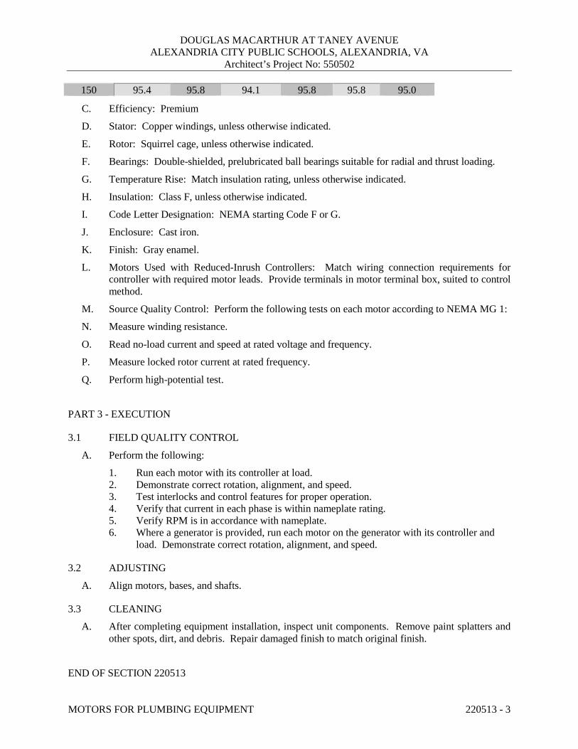
DOUGLAS MACARTHUR AT TANEY AVENUE ALEXANDRIA CITY PUBLIC SCHOOLS, ALEXANDRIA, VA
Architect’s Project No: 550502
MOTORS FOR PLUMBING EQUIPMENT 220513 - 3
150 95.4 95.8 94.1 95.8 95.8 95.0
C. Efficiency: Premium
D. Stator: Copper windings, unless otherwise indicated.
E. Rotor: Squirrel cage, unless otherwise indicated.
F. Bearings: Double-shielded, prelubricated ball bearings suitable for radial and thrust loading.
G. Temperature Rise: Match insulation rating, unless otherwise indicated.
H. Insulation: Class F, unless otherwise indicated.
I. Code Letter Designation: NEMA starting Code F or G.
J. Enclosure: Cast iron.
K. Finish: Gray enamel.
L. Motors Used with Reduced-Inrush Controllers: Match wiring connection requirements forcontroller with required motor leads. Provide terminals in motor terminal box, suited to controlmethod.
M. Source Quality Control: Perform the following tests on each motor according to NEMA MG 1:
N. Measure winding resistance.
O. Read no-load current and speed at rated voltage and frequency.
P. Measure locked rotor current at rated frequency.
Q. Perform high-potential test.
PART 3 - EXECUTION
3.1 FIELD QUALITY CONTROL
A. Perform the following:
1. Run each motor with its controller at load.2. Demonstrate correct rotation, alignment, and speed.3. Test interlocks and control features for proper operation.4. Verify that current in each phase is within nameplate rating.5. Verify RPM is in accordance with nameplate.6. Where a generator is provided, run each motor on the generator with its controller and
load. Demonstrate correct rotation, alignment, and speed.
3.2 ADJUSTING
A. Align motors, bases, and shafts.
3.3 CLEANING
A. After completing equipment installation, inspect unit components. Remove paint splatters andother spots, dirt, and debris. Repair damaged finish to match original finish.
END OF SECTION 220513

DOUGLAS MACARTHUR AT TANEY AVENUE ALEXANDRIA CITY PUBLIC SCHOOLS, ALEXANDRIA, VA
Architect’s Project No: 550502
SLEEVES AND SLEEVE SEALS FOR PLUMBING PIPING 220517 - 1
SECTION 220517 - SLEEVES AND SLEEVE SEALS FOR PLUMBING PIPING
PART 1 - GENERAL
1.1 RELATED DOCUMENTS
A. Provisions of the Contract and of the Contract Documents apply to this Section.
1.2 SUBMITTALS
A. Product Data: For each type of product indicated.
PART 2 - PRODUCTS
2.1 SLEEVES
A. Cast-Iron Wall Pipes: Cast or fabricated of cast or ductile iron and equivalent to ductile-iron pressure pipe, with plain ends and integral waterstop unless otherwise indicated.
B. Galvanized-Steel Wall Pipes: ASTM A 53/A 53M, Schedule 40, with plain ends and welded steel collar; zinc coated.
C. Galvanized-Steel-Pipe Sleeves: ASTM A 53/A 53M, Type E, Grade B, Schedule 40, zinc coated, with plain ends.
D. Galvanized-Steel-Sheet Sleeves: 0.0239-inch (0.6-mm) minimum thickness; round tube closed with welded longitudinal joint.
2.2 STACK-SLEEVE FITTINGS
A. Available Manufacturers:
1. Smith, Jay R. Mfg. Co. 2. Wade 3. Zurn Specification Drainage Operation; Zurn Plumbing Products Group.
B. Description: Manufactured, cast-iron sleeve with integral clamping flange. Include clamping ring, bolts, and nuts for membrane flashing.
1. Underdeck Clamp: Clamping ring with setscrews.

DOUGLAS MACARTHUR AT TANEY AVENUE ALEXANDRIA CITY PUBLIC SCHOOLS, ALEXANDRIA, VA
Architect’s Project No: 550502
SLEEVES AND SLEEVE SEALS FOR PLUMBING PIPING 220517 - 2
2.3 MECHANICAL SLEEVE SEALS
A. Description: Modular sealing element unit, designed for field assembly, to fill annular space between pipe and sleeve.
1. Available Manufacturers:
a. Advance Products & Systems, Inc. b. Calpico, Inc. c. GPT, EnPro Industries d. Metraflex Co. e. Pipeline Seal and Insulator, Inc.
2. Sealing Elements: EPDM interlocking links shaped to fit surface of pipe. Include type and number required for pipe material and size of pipe.
3. Pressure Plates: Plastic. Include two for each sealing element. 4. Connecting Bolts and Nuts: Stainless steel of length required to secure pressure plates to
sealing elements.
PART 3 - EXECUTION
3.1 SLEEVE INSTALLATION
A. Install sleeves for piping passing through penetrations in floors, partitions, roofs, and walls.
B. For sleeves that will have sleeve-seal system installed, select sleeves of size large enough to provide 1-inch annular clear space between piping and concrete slabs and walls.
1. Sleeves are not required for core-drilled holes.
C. Install sleeves in concrete floors, concrete roof slabs, and concrete walls as new slabs and walls are constructed.
1. Permanent sleeves are not required for holes in slabs formed by molded-PE or -PP sleeves.
2. Cut sleeves to length for mounting flush with both surfaces.
a. Exception: Extend sleeves installed in floors of mechanical equipment areas or other wet areas 2 inches above finished floor level.
3. Using grout, seal the space outside of sleeves in slabs and walls without sleeve-seal system.
D. Install sleeves for pipes passing through interior partitions.
1. Cut sleeves to length for mounting flush with both surfaces. 2. Install sleeves that are large enough to provide ¼” clear space between sleeve and pipe or
pipe insulation.
DOUGLAS MACARTHUR AT TANEY AVENUE ALEXANDRIA CITY PUBLIC SCHOOLS, ALEXANDRIA, VA
Architect’s Project No: 550502
SLEEVES AND SLEEVE SEALS FOR PLUMBING PIPING 220517 - 3
3. Seal annular space between sleeve and piping or piping insulation; use joint sealantsappropriate for size, depth, and location of joint. Comply with requirements for sealants.
E. Fire Ratings: Maintain indicated fire rating of walls, partitions, ceilings, and floors at pipepenetrations. Seal pipe penetrations with firestop materials.
3.2 STACK-SLEEVE-FITTING INSTALLATION
A. Install stack-sleeve fittings in new slabs as slabs are constructed.
1. Install fittings that are large enough to provide ¼” clear space between sleeve and pipe orpipe insulation.
2. Secure flashing between clamping flanges for pipes penetrating floors with membranewaterproofing. Comply with requirements for flashing specified in Division 07 Section"Sheet Metal Flashing and Trim."
3. Install section of cast-iron soil pipe to extend sleeve to 2 inches above finished floorlevel.
4. Extend cast-iron sleeve fittings below floor slab as required to secure clamping ring ifring is specified.
5. Using grout, seal the space around outside of stack-sleeve fittings.
B. Fire Rating: Maintain indicated fire rating at pipe penetrations. Seal pipe penetrations withfirestop materials.
3.3 SLEEVE-SEAL SYSTEM INSTALLATION
A. Install sleeve-seal systems in sleeves in exterior concrete walls and slabs-on-grade at servicepiping entries into building unless otherwise indicated.
B. Select type, size, and number of sealing elements required for piping material and size and forsleeve ID or hole size. Position piping in center of sleeve. Center piping in penetration,assemble sleeve-seal system components, and install in annular space between piping andsleeve. Tighten bolts against pressure plates that cause sealing elements to expand and make awatertight seal.
3.4 SLEEVE AND SLEEVE-SEAL SCHEDULE
A. Use sleeves and sleeve seals for the following piping-penetration applications:
1. Exterior Concrete Walls above Grade, below Grade, Concrete Slabs-on-Grade, andConcrete Slabs above Grade:
a. Piping Smaller Than 6”: Cast-iron wall sleeves with sleeve-seal system.1) Select sleeve size to allow for one inch (1”) annular clear space between
piping and sleeve for installing sleeve-seal system.b. Piping 6” and Larger: Galvanized-steel-pipe sleeves with sleeve-seal system.

DOUGLAS MACARTHUR AT TANEY AVENUE ALEXANDRIA CITY PUBLIC SCHOOLS, ALEXANDRIA, VA
Architect’s Project No: 550502
SLEEVES AND SLEEVE SEALS FOR PLUMBING PIPING 220517 - 4
END OF SECTION 220517
DOUGLAS MACARTHUR AT TANEY AVENUE ALEXANDRIA CITY PUBLIC SCHOOLS, ALEXANDRIA, VA
Architect’s Project No: 550502
METERS AND GAGES FOR PLUMBING PIPING 220519-1
SECTION 220519 - METERS AND GAGES FOR PLUMBING PIPING
PART 1 - GENERAL
1.1 RELATED DOCUMENTS
A. Provisions of the Contract and of the Contract Documents apply to this Section.
1.2 SUBMITTALS
A. Product Data: For each type of product indicated.
B. Operation and Maintenance Data: For meters and gages to include in operation and maintenance manuals.
1.3 ABBREVIATIONS:
A. AFF Above finished floor B. F Fahrenheit C. SS Stainless Steel
PART 2 - PRODUCTS
2.1 LIQUID-IN-GLASS THERMOMETERS
A. Metal-Case, Industrial-Style, Liquid-in-Glass Thermometers:
1. Available Manufacturers:
a. Flo Fab Inc. b. Miljoco Corporation. c. Palmer Wahl Instrumentation Group. d. Tel-Tru Manufacturing Company. e. Trerice, H. O. Co. f. Weiss Instruments, Inc. g. Winters Instruments - U.S.
2. Standard: ASME B40.200. 3. Case: Cast aluminum; 9-inch nominal size unless otherwise indicated. 4. Case Form: Adjustable angle unless otherwise indicated. 5. Tube: Glass with magnifying lens and blue or red organic liquid. 6. Tube Background: Non-reflective aluminum with permanently etched scale markings
graduated in degrees F. 7. Window: Glass

DOUGLAS MACARTHUR AT TANEY AVENUE ALEXANDRIA CITY PUBLIC SCHOOLS, ALEXANDRIA, VA
Architect’s Project No: 550502
METERS AND GAGES FOR PLUMBING PIPING 220519-2
8. Stem: Aluminum length = 1/2 pipe diameter, 1/2 duct width or 12” whichever is less.
a. Air-Duct Installation: Provide ventilated shroud.b. Thermowell Installation: Provide Bare stem.
9. Connector: 1-1/4 inches, with ASME B1.1 screw threads.10. Accuracy: Plus or minus 1 percent of scale range or one scale division, to a maximum of
1.5 percent of scale range.
2.2 THERMOWELLS
A. Thermowells:
1. Standard: ASME B40.200.2. Description: Pressure-tight, socket-type fitting made for insertion into threaded fitting.3. Material: Brass.4. Type: Stepped shank unless straight or tapered shank is indicated.5. External Threads: NPS 1/2, NPS 3/4, or NPS 1, ASME B1.20.1 pipe threads.6. Internal Threads: 1/2, 3/4, and 1 inch, with ASME B1.1 screw threads.7. Bore: Diameter required to match thermometer bulb or stem.8. Insertion Length: Length required to match thermometer bulb or stem.9. Lagging Extension: Include on thermowells for insulated piping and tubing.10. Bushings: For converting size of thermowell's internal screw thread to size of
thermometer connection.
2.3 PRESSURE GAGES
A. Direct-Mounted, Metal-Case, Dial-Type Pressure Gages:
1. Available Manufacturers:
a. AMETEK, Inc.; U.S. Gauge.b. Ashcroft Inc.c. Ernst Flow Industries.d. Flo Fab Inc.e. Marsh Bellofram.f. Miljoco Corporation.g. Noshok.h. Palmer Wahl Instrumentation Group.i. REOTEMP Instrument Corporation.j. Tel-Tru Manufacturing Company.k. Trerice, H. O. Co.l. Watts Regulator Co.; a div. of Watts Water Technologies, Inc.m. Weiss Instruments, Inc.n. WIKA Instrument Corporation - USA.o. Winters Instruments - U.S.
2. Standard: ASME B40.100.

DOUGLAS MACARTHUR AT TANEY AVENUE ALEXANDRIA CITY PUBLIC SCHOOLS, ALEXANDRIA, VA
Architect’s Project No: 550502
METERS AND GAGES FOR PLUMBING PIPING 220519-3
3. Case: Solid-front, lead-free, pressure relief type; stainless steel; 4-1/2-inch nominal diameter.
4. Pressure-Element Assembly: Bourdon tube unless otherwise indicated. 5. Pressure Connection: Brass, with NPS 1/4, ASME B1.20.1 pipe threads and bottom-
outlet type unless back-outlet type is indicated. 6. Movement: Phosphor bronze. 7. Dial: Nonreflective aluminum with permanently etched scale markings graduated in psi. 8. Pointer: Dark-colored metal. 9. Window: Glass. 10. Ring: Brass. 11. Accuracy: + or – 1.0 percent of full scale.
2.4 GAGE ATTACHMENTS
A. Snubbers: ASME B40.100, brass; with NPS 1/4, ASME B1.20.1 pipe threads and porous-metal-type surge-dampening device. Include extension for use on insulated piping.
B. Siphons: Loop-shaped section of brass pipe with NPS 1/4 pipe threads.
C. Valves: Brass or stainless-steel needle, with NPS 1/4, ASME B1.20.1 pipe threads.
2.5 TEST PLUGS
A. Manufacturers: Subject to compliance with requirements, provide products by one of the following:
1. Flow Design, Inc. 2. Miljoco Corporation. 3. National Meter, Inc. 4. Peterson Equipment Co., Inc. 5. Sisco Manufacturing Company, Inc. 6. Trerice, H. O. Co. 7. Watts Regulator Co.; a div. of Watts Water Technologies, Inc. 8. Weiss Instruments, Inc.
B. Description: Test-station fitting made for insertion into piping tee fitting.
C. Body: Brass or stainless steel with core inserts and gasketed and threaded cap. Include extended stem on units to be installed in insulated piping.
D. Thread Size: NPS 1/2, ASME B1.20.1 pipe thread.
E. Minimum Pressure and Temperature Rating: 500 psig at 200 deg F.
F. Core Inserts: Chlorosulfonated polyethylene synthetic and EPDM self-sealing rubber.

DOUGLAS MACARTHUR AT TANEY AVENUE ALEXANDRIA CITY PUBLIC SCHOOLS, ALEXANDRIA, VA
Architect’s Project No: 550502
METERS AND GAGES FOR PLUMBING PIPING 220519-4
PART 3 - EXECUTION
3.1 INSTALLATION
A. Install thermowells with socket extending to center of pipe in piping tees.
B. Install thermowells of sizes required to match thermometer connectors. Include bushings to match sizes.
C. Install thermowells with extensions on insulated piping.
D. Install direct-mounted thermometers in thermowells and adjust positions.
E. Install pressure gages in piping tees located between 36” and 60” above finished floor unless otherwise indicated.
F. Install valve and snubber for each pressure gage.
G. Install test plugs in piping tees at locations indicated.
H. Assemble and install connections, tubing, and accessories between flow-measuring elements and flowmeters according to manufacturer's written instructions.
I. Install flowmeter elements in accessible positions in piping systems.
J. Install permanent indicators on walls or brackets at 50” above finished floor unless otherwise indicated..
K. Install connection fittings in accessible locations for attachment to portable indicators. L. Install thermometers in the following locations:
1. Inlet and outlet of each water heater.
M. Install pressure gages in the following locations: 1. Inlet and outlet of each water heater. 2. Suction and discharge of each pump.
N. Install a test plug at each thermometer and pressure gauge.
3.2 THERMOMETER SCALE-RANGE SCHEDULE A. Scale Range for Domestic Cold-Water Piping: 0 to 100 F with 2-degree scale divisions. B. Scale Range for Domestic Hot-Water and Hot-Water Recirculation Piping 30 to 240 F with 2-
degree scale divisions.
3.3 PRESSURE-GAGE SCALE-RANGE SCHEDULE
A. Scale Range for Domestic Water Piping: 0 psi to 100 psi. 1. Provide pressure scale range so that normal operating high and low pressures are within
25%-75% of the full scale range.
END OF SECTION 220519
DOUGLAS MACARTHUR AT TANEY AVENUE ALEXANDRIA CITY PUBLIC SCHOOLS, ALEXANDRIA, VA
Architect’s Project No: 550502
GENERAL DUTY VALVES FOR PLUMBING PIPING 220523 - 1
SECTION 220523 – GENERAL DUTY VALVES FOR PLUMBING PIPING
PART 1 - GENERAL
1.1 RELATED DOCUMENTS
A. Provisions of the Contract and of the Contract Documents apply to this Section.
1.2 DEFINITIONS
A. The following are standard abbreviations for valves:1. CWP: Cold working pressure.2. EPDM: Ethylene-propylene-diene terpolymer rubber.3. MPTFE: Modified polytetrafluoroethylene plastic.4. NBR: Acrylonitrile-butadiene rubber.5. PTFE: Polytetrafluoroethylene plastic.6. RPTFE: Reinforced polytetrafluoroethylene plastic.7. SWP: Steam working pressure.8. TFE: Tetrafluoroethylene plastic.9. WOG: Water Oil Gas.
1.3 SUBMITTALS
A. Product Data: For each type of valve proposed. Include body, seating, and trim materials;valve design; pressure and temperature classifications; end connections; arrangement;dimensions; and required clearances. Include proposed specialties and accessories.
1.4 QUALITY ASSURANCE
A. ASME Compliance: ASME B31.1 for power piping valves and ASME B31.9 for buildingservices piping valves.1. Exceptions: Domestic hot- and cold-water valves unless referenced.
B. ASME Compliance for Ferrous Valves: ASME B16.10 and ASME B16.34 for dimension anddesign criteria.
C. NSF Compliance:1. NSF 61 for valve materials for potable-water service.2. NSF 372 for Lead content requirements in drinking water system components.
1.5 DELIVERY, STORAGE, AND HANDLING
A. Prepare valves for shipping as follows:1. Protect internal parts against rust and corrosion.

DOUGLAS MACARTHUR AT TANEY AVENUE ALEXANDRIA CITY PUBLIC SCHOOLS, ALEXANDRIA, VA
Architect’s Project No: 550502
GENERAL DUTY VALVES FOR PLUMBING PIPING 220523 - 2
2. Protect threads, flange faces, grooves, and weld ends. 3. Set ball valves open to minimize exposure of functional surfaces. 4. Set butterfly valves closed or slightly open. 5. Block check valves in either closed or open position.
B. Use the following precautions during storage: 1. Maintain valve end protection. 2. Store valves indoors and maintain at higher than ambient dew-point temperature. If
outdoor storage is necessary, store valves off the ground in watertight enclosures.
C. Use sling to handle large valves; rig sling to avoid damage to exposed parts. Do not use handwheels or stems as lifting or rigging points.
PART 2 - PRODUCTS
2.1 VALVES, GENERAL
A. Refer to Part 3 "Valve Applications" Article for applications of valves.
B. Bronze & Brass: Shall be dezincification resistant. (Zinc content shall be less than 15%)
C. Bronze Valves: 2” and smaller with threaded or soldered ends, unless otherwise indicated.
D. Ferrous Valves: 2-1/2” and larger with flanged ends, unless otherwise indicated.
E. Valve Pressure and Temperature Ratings: Not less than indicated for system pressure and temperature.
F. Valve Sizes: Same as the larger of the upstream or downstream pipe, unless otherwise indicated.
G. Valve Actuators: 1. As indicated in other Part 2 articles. 2. Where indicated, provide a chain actuator. 3. Chain Actuator: For attachment to valves of size and mounting height indicated. 4. Wrench: For plug valves with square heads. Furnish Owner with 1 wrench for every 10
plug valves, for each size square plug head.
H. Extended Valve Stems: Provide on insulated valves.
I. Valve Flanges: Provide ASME B16.1 for cast-iron valves, ASME B16.5 for steel, and ASME B16.24 for bronze.
J. Valve Grooved Ends: AWWA C606.
K. Threaded: With threads according to ASME B1.20.1.
L. Valve Bypass and Drain Connections: MSS SP-45.
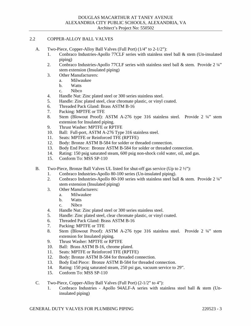
DOUGLAS MACARTHUR AT TANEY AVENUE ALEXANDRIA CITY PUBLIC SCHOOLS, ALEXANDRIA, VA
Architect’s Project No: 550502
GENERAL DUTY VALVES FOR PLUMBING PIPING 220523 - 3
2.2 COPPER-ALLOY BALL VALVES
A. Two-Piece, Copper-Alloy Ball Valves (Full Port) (1/4” to 2-1/2”): 1. Conbraco Industries-Apollo 77CLF series with stainless steel ball & stem (Un-insulated
piping) 2. Conbraco Industries-Apollo 77CLF series with stainless steel ball & stem. Provide 2 ¼”
stem extension (Insulated piping) 3. Other Manufacturers:
a. Milwaukee b. Watts c. Nibco
4. Handle Nut: Zinc plated steel or 300 series stainless steel. 5. Handle: Zinc plated steel, clear chromate plastic, or vinyl coated. 6. Threaded Pack Gland: Brass ASTM B-16 7. Packing: MPTFE or TFE 8. Stem (Blowout Proof): ASTM A-276 type 316 stainless steel. Provide 2 ¼” stem
extension for Insulated piping. 9. Thrust Washer: MPTFE or RPTFE 10. Ball: Full-port, ASTM A-276 Type 316 stainless steel. 11. Seats: MPTFE or Reinforced TFE (RPTFE) 12. Body: Bronze ASTM B-584 for solder or threaded connection. 13. Body End Piece: Bronze ASTM B-584 for solder or threaded connection. 14. Rating: 150 psig saturated steam, 600 psig non-shock cold water, oil, and gas. 15. Conform To: MSS SP-110
B. Two-Piece, Bronze Ball Valves UL listed for shut-off gas service (Up to 2 ½”): 1. Conbraco Industries-Apollo 80-100 series (Un-insulated piping). 2. Conbraco Industries-Apollo 80-100 series with stainless steel ball & stem. Provide 2 ¼”
stem extension (Insulated piping) 3. Other Manufacturers:
a. Milwaukee b. Watts c. Nibco
4. Handle Nut: Zinc plated steel or 300 series stainless steel. 5. Handle: Zinc plated steel, clear chromate plastic, or vinyl coated. 6. Threaded Pack Gland: Brass ASTM B-16 7. Packing: MPTFE or TFE 8. Stem (Blowout Proof): ASTM A-276 type 316 stainless steel. Provide 2 ¼” stem
extension for Insulated piping. 9. Thrust Washer: MPTFE or RPTFE 10. Ball: Brass ASTM B-16, chrome plated. 11. Seats: MPTFE or Reinforced TFE (RPTFE) 12. Body: Bronze ASTM B-584 for threaded connection. 13. Body End Piece: Bronze ASTM B-584 for threaded connection. 14. Rating: 150 psig saturated steam, 250 psi gas, vacuum service to 29”. 15. Conform To: MSS SP-110
C. Two-Piece, Copper-Alloy Ball Valves (Full Port) (2-1/2” to 4”): 1. Conbraco Industries - Apollo 94ALF-A series with stainless steel ball & stem (Un-
insulated piping)

DOUGLAS MACARTHUR AT TANEY AVENUE ALEXANDRIA CITY PUBLIC SCHOOLS, ALEXANDRIA, VA
Architect’s Project No: 550502
GENERAL DUTY VALVES FOR PLUMBING PIPING 220523 - 4
2. Conbraco Industries - Apollo 94ALF-A series with stainless steel ball & stem. Provide 2¼” stem extension (Insulated piping)
3. Other Manufacturers:a. Milwaukeeb. Wattsc. Nibco.
4. Handle Nut: Zinc plated steel or 300 series stainless steel.5. Handle: Zinc plated steel, clear chromate plastic, or vinyl coated.6. Threaded Pack Gland: Brass ASTM B-16 Alloy 3607. Packing: RPTFE or TFE8. Stem (Blowout Proof): ASTM A-276 type 316 stainless steel. Provide 2 ¼” stem
extension for Insulated piping.9. Thrust Washer: MPTFE or Reinforced TFE10. Ball: Full-port, ASTM A-276 Type 316 stainless steel.11. Seats: MPTFE or Reinforced TFE12. Body: Bronze ASTM B-584 for solder or threaded connection.13. Body End Piece: Bronze ASTM B-584 for solder or threaded connection.14. Rating: 150 psig saturated steam, 600 psig non-shock cold water, oil, and gas.15. Conform To: MSS SP-110
2.3 LARGE GAS BALL VALVES (ABOVE 2 ½” to 10”):
A. Carbon Steel ANSI class 150, flanged, standard port ball valve with stainless steel ball andstem.1. Conbraco Industries-Apollo 88A-140 series2. Other Manufacturers:
a. Milwaukeeb. Wattsc. Nibco
3. Provide gear operator with oversized hand wheel.4. Packing Gland: ASTM A108 Type 12155. Packing: RPTFE or TFE6. Stem (Blowout Proof): ASTM A108 Type 12157. Ball: Standard-port, ASTM A-276 Type 316 stainless steel solid ball.8. Seats: RPTFE9. Thrust Washer: RPTFE.10. Body: Carbon steel ASTM A216 WCB.11. Body Nut: ASTM A194, grade 2H.12. UL (YRPV): Listed for gas shut-off service.13. Rating: 150 psig saturated steam
2.4 FERROUS-ALLOY BUTTERFLY VALVES
A. General: Butterfly valves shall provide bi-directional bubble tight dead end service without adownstream flange.
B. Wafer-lug type butterfly valves:1. Conbraco Industries-Apollo 141(wafer)/143(lug)

DOUGLAS MACARTHUR AT TANEY AVENUE ALEXANDRIA CITY PUBLIC SCHOOLS, ALEXANDRIA, VA
Architect’s Project No: 550502
GENERAL DUTY VALVES FOR PLUMBING PIPING 220523 - 5
2. Other Manufacturers: a. Stockham b. Demco c. Nibco
3. Shaft: ASTM A-582 Type 416 Stainless steel single piece through shaft. 4. Collar Bushing: ASTM B-124 Brass or PTFE. 5. Stem Seal: EPDM OR Buna-N Rubber 6. Body Seal: EPDM Rubber 7. Upper Bushing: CDA 122 Copper or PTFE 8. Liner: EPDM Rubber 9. Disc: ASTM B-148 alloy 954/955 aluminum bronze. 10. Lower Bushing: CDA 122 copper or PTFE. 11. Body Wafer: ASTM A-536 Ductile Iron or ASTM A-126 CL. B cast iron. 12. Body Lug: ASTM A-536 Ductile Iron or ASTM A-126 CL. B cast iron. 13. Ratings:
a. 2” through 12” 200 psig CWP. b. 14” through 24” 150 psig CWP.
14. Conform To: MSS SP-67, MSS SP-25, API-609 15. Operator:
a. Valves up to and including 6”: Lever-lock operator. b. Valves 8” and larger: Self locking worm gear operator equipped with adjustable
stops at open and shut positions.
C. Grooved-End 300 psig butterfly valves: 1. Conbraco Industries-Apollo SJ-900N/SJ-900N-L 2. Other Manufacturers:
a. Victaulic b. Nibco
3. Upper Stem: ASTM A-582 Type 416 Stainless steel. 4. Upper Bearing: Split metal. 5. O-Ring: EPDM 6. Body: ASTM A-395 ductile iron with polyimide coating. 7. Disc: ASTM A-395 ductile iron with EPDM encapsulation. 8. Lower Bearing: Split metal. 9. Dust Plug: PVC 10. Rating: 300 psig CWP. 11. Conform To: MSS SP-67 12. Operator:
a. Valves up to and including 6”: Lever-lock operator. b. Valves 8” and larger: Self locking worm gear operator equipped with adjustable
stops at open and shut positions.
D. Flanged 200 psig butterfly valves: 1. Conbraco Industries-Apollo SJ-200 2. Other Manufacturers:
a. Nibco 3. Upper Stem: ASTM A-582 Type 416 Stainless steel. 4. Upper Bushing: TFE over porous bronze, steel backed. 5. O-Ring: EPDM 6. Body: ASTM A-126 Class B cast iron with polyimide coating.

DOUGLAS MACARTHUR AT TANEY AVENUE ALEXANDRIA CITY PUBLIC SCHOOLS, ALEXANDRIA, VA
Architect’s Project No: 550502
GENERAL DUTY VALVES FOR PLUMBING PIPING 220523 - 6
7. Disc: ASTM A-395 ductile iron with EPDM encapsulation. 8. Lower Bushing: TFE over porous bronze, steel backed. 9. Lower Stem: ASTM A-582 Type 416 Stainless steel. 10. Dust Plug: PVC 11. Rating: 200 psig CWP. 12. Conform To: MSS SP-67 and MSS SP-25 13. Operator:
a. Valves up to and including 6”: Lever-lock operator. b. Valves 8” and larger: Self locking worm gear operator equipped with adjustable
stops at open and shut positions.
E. Flanged 200 psig butterfly valves for Gas Service: 1. NIBCO Model FC-2765-0 2. Upper Stem: ASTM A-582 Type 416 Stainless steel. 3. Upper Bushing: TFE over porous bronze, steel backed. 4. O-Ring: EPDM 5. Body: ASTM A-126 Class B cast iron with polyimide coating. 6. Disc: ASTM A-395 ductile iron with EPDM encapsulation. 7. Lower Bushing: TFE over porous bronze, steel backed. 8. Lower Stem: ASTM A-582 Type 416 Stainless steel. 9. Dust Plug: PVC 10. Rating: 200 psig CWP. 11. Conform To: MSS SP-67 and MSS SP-25 12. Operator:
a. Valves up to and including 6”: Lever-lock operator. b. Valves 8” and larger: Self locking worm gear operator equipped with adjustable
stops at open and shut positions.
2.5 BRONZE CHECK VALVES
A. Bronze, Horizontal Swing Check Valves: 1. Conbraco Industries-Apollo 161S/T 2. Other Manufacturers:
a. Milwaukee b. Stockham c. Nibco
3. Bonnet: ASTM B-62 bronze. 4. Body: ASTM B-62 bronze. 5. Hinge Pin: ASTM B-140 alloy C31400 bronze, or B-134 alloy C23000 bronze. 6. Disc Hanger:
a. Sizes ¼” thru ¾”: Type 304 stainless steel. b. Sizes 1” and larger: ASTM B-62 bronze.
7. Hanger Nut: ASTM B-16 bronze. 8. Disc Holder: ASTM B-62 bronze. 9. Seat Disc:
a. Water and Other Heat Transfer Fluids: ASTM B-62 bronze. b. Steam: TFE
10. Seat Disc Nut: ASTM B-16 or B-62 bronze. 11. Hinge Pin Plug: ASTM B-140 alloy C31600 bronze.

DOUGLAS MACARTHUR AT TANEY AVENUE ALEXANDRIA CITY PUBLIC SCHOOLS, ALEXANDRIA, VA
Architect’s Project No: 550502
GENERAL DUTY VALVES FOR PLUMBING PIPING 220523 - 7
12. Seat Disc Washer (When Provided): ASTM B-98 alloy C65500 or B-103 bronze. 13. Rating: 125 psig SWP and 200 psig CWP. 14. Conform To: MSS SP-80
B. Bronze, Inline Spring Loaded Check Valves: 1. Conbraco Industries-Apollo 61-100 series 2. Other Manufacturers:
a. Milwaukee b. Stockham c. Nibco
3. Body: ASTM B-584 alloy C84400 bronze. 4. Retainer/Stem: ASTM B16 brass or ASTM A-582 alloy C30300 stainless steel. 5. Ball Check: RPTFE or 6. Disc Holder 316 Stainless steel
a. Disc: 1) Water, Oil, Gas: Buna-N 2) Steam: TFE
b. Seat Screw: ASTM A-276 alloy S43000 stainless steel. c. Body End: ASTM B-584 alloy C84400 bronze. d. Rating: 125 psig SWP and 250 psig CWP.
7. Guide: ASTM B16 Brass 8. Spring: Type 316 stainless steel. 9. Rating: 125 psig SWP and 400 psig WOG.
2.6 IRON BODY CHECK VALVES
A. Iron Body, Horizontal Swing Check Valves: 1. Conbraco Industries-Apollo 910F 2. Other Manufacturers:
a. Milwaukee b. Stockham c. Nibco
3. Body Bolt: ASTM A-307 steel. 4. Bonnet: ASTM A-126 class B cast iron. 5. Body Gasket: Synthetic Fibers. 6. Body Nut: ASTM A-307 steel 7. Side Plug: ASTM B-16 alloy C36000 Brass. 8. Hanger Pin: ASTM B-16 alloy C36000 Brass. 9. Hanger: ASTM B-584 alloy C84400 cast bronze. 10. Disc: ASTM B-584 alloy C84400 cast bronze or ASTM A-536 ductile iron w/bronze face
ring. 11. Seat Ring: ASTM B-584 alloy C84400 cast bronze. 12. Disc Nut: ASTM B-16 alloy C36000. 13. Body: ASTM A-126 class B cast iron. 14. Disc Bolt: ASTM B-16 alloy C36000 Brass. 15. Disc Plate: ASTM A-126 class B cast iron. 16. Disc Cage: ASTM A-126 class B cast iron. 17. Rating: 125 psig SWP and 200 psig CWP. 18. Conform To: MSS SP-71 Type 1.

DOUGLAS MACARTHUR AT TANEY AVENUE ALEXANDRIA CITY PUBLIC SCHOOLS, ALEXANDRIA, VA
Architect’s Project No: 550502
GENERAL DUTY VALVES FOR PLUMBING PIPING 220523 - 8
B. Grooved-End, Ductile-Iron Spring Assisted Check Valves: Apollo SJ-900N with EPDM discseal.
C. Spring Actuated Silent Check Valves:1. NIBCO Model F-9102. Other Manufacturers:
a. Milwaukeeb. Stockham
3. Body: ASTM A48 class 35 cast iron.4. Seat: ASTM B-584 alloy C83600 (B) bronze.5. Disc: ASTM B-584 alloy C83600 bronze.6. Spring: Type 302 ASTM A313 stainless steel.7. Bushing:
a. 6” and Smaller: ASTM B-16 brassb. 8” and Larger: ASTM B-584 alloy C83600 bronze.
8. Set Screws: Type 304 ASTM A-276 stainless steel.9. Rating: 200 psig CWP.10. Conform To: MIL-V-18436F
PART 3 - EXECUTION
3.1 EXAMINATION
A. Examine valve interior for cleanliness, freedom from foreign matter, and corrosion. Removespecial packing materials, such as blocks, used to prevent disc movement during shipping andhandling.
B. Operate valves in positions from fully-open to fully-closed. Examine guides and seats madeaccessible by such operations.
C. Examine threads on valve and mating pipe for form and cleanliness.
D. Examine mating flange faces for conditions that might cause leakage. Check bolting for propersize, length, and material. Verify that gasket is of proper size, that its material composition issuitable for service, and that it is free from defects and damage.
E. Do not attempt to repair defective valves; replace with new valves.
3.2 VALVE INSTALLATION
A. Install valves with unions or flanges at each piece of equipment arranged to allow service,maintenance, and equipment removal without system shutdown.
B. Locate valves for easy access.
C. Install valves in horizontal piping with stem at or above center of pipe.

DOUGLAS MACARTHUR AT TANEY AVENUE ALEXANDRIA CITY PUBLIC SCHOOLS, ALEXANDRIA, VA
Architect’s Project No: 550502
GENERAL DUTY VALVES FOR PLUMBING PIPING 220523 - 9
D. Install valves in position to allow full stem movement.
E. Install chainwheels on operators for ball and butterfly valves 4” and larger and more than 96 inches above finished floor. Extend chains to 60 inches above finished floor.
F. Install check valves for proper direction of flow and as follows: 1. Swing Check Valves: In horizontal position with hinge pin level. 2. Center-Guided and Plate-Type Check Valves: In horizontal or vertical position, between
flanges. 3. Lift Check Valves: With stem upright and plumb.
G. Shutoff valves shall be located on each floor, on takeoffs from all vertical risers, branch lines from the mains, and at the connection to each fixture.
3.3 ADJUSTING
A. Adjust valve packing after piping systems have been tested and put into service but before final testing and balancing. Replace valves if persistent leaking occurs.
3.4 VALVE APPLICATIONS
A. Refer to piping Sections for specific valve applications. If valve applications are not indicated, use the following: 1. Shutoff Service: Ball or butterfly valves. 2. Throttling Service: Ball or butterfly valves. 3. Pump Discharge: Spring-loaded, lift-disc check valves and ball or butterfly valves.
B. If valves with specified SWP classes or CWP ratings are not available, the same types of valves with higher SWP class or CWP ratings may be substituted.
C. Compressed-Air Piping: Use the following types of valves: 1. Valves, NPS 2” and Smaller: Two-Piece, Copper-Alloy Ball Valves (Full Port). 2. Equipment-Isolation Valves: Safety-Vent, Copper-Alloy Ball Valves (For Compressed
Air). 3. Valves, NPS 2-1/2” and 3”: Two-piece or three-piece, Copper-Alloy Ball Valves (Full
Port). 4. Check Valves, NPS 2” and Smaller: Bronze, Inline Lift Check Valves. 5. Check Valves, NPS 2-1/2” and Larger: Spring Actuated Silent Check Valves.
D. Domestic Water Piping: Use the following types of valves: 1. Valves, NPS 2” and Smaller: Two-Piece, Copper-Alloy Ball Valves (Full Port). 2. Valves, NPS 2-1/2” and 3”:
a. Two-piece or three-piece, Copper-Alloy Ball Valves (Full Port). b. Wafer-Lug, grooved-end, or flanged butterfly valves.
3. Valves, NPS 4” and Larger: Wafer-Lug, grooved-end, or flanged butterfly valves. 4. Pump Discharge Check Valves (Horizontal or Vertical), NPS 2” and Smaller: Bronze,
Inline Lift Check Valves.
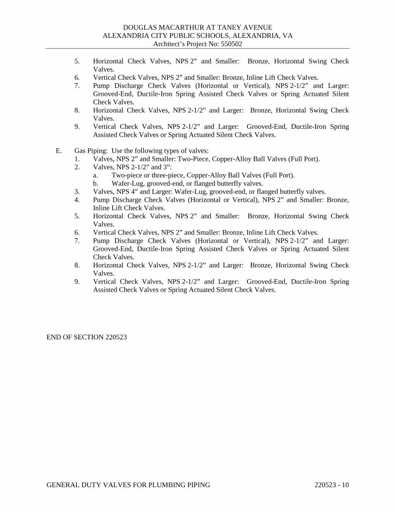
DOUGLAS MACARTHUR AT TANEY AVENUE ALEXANDRIA CITY PUBLIC SCHOOLS, ALEXANDRIA, VA
Architect’s Project No: 550502
GENERAL DUTY VALVES FOR PLUMBING PIPING 220523 - 10
5. Horizontal Check Valves, NPS 2” and Smaller: Bronze, Horizontal Swing Check Valves.
6. Vertical Check Valves, NPS 2” and Smaller: Bronze, Inline Lift Check Valves. 7. Pump Discharge Check Valves (Horizontal or Vertical), NPS 2-1/2” and Larger:
Grooved-End, Ductile-Iron Spring Assisted Check Valves or Spring Actuated Silent Check Valves.
8. Horizontal Check Valves, NPS 2-1/2” and Larger: Bronze, Horizontal Swing Check Valves.
9. Vertical Check Valves, NPS 2-1/2” and Larger: Grooved-End, Ductile-Iron Spring Assisted Check Valves or Spring Actuated Silent Check Valves.
E. Gas Piping: Use the following types of valves: 1. Valves, NPS 2” and Smaller: Two-Piece, Copper-Alloy Ball Valves (Full Port). 2. Valves, NPS 2-1/2” and 3”:
a. Two-piece or three-piece, Copper-Alloy Ball Valves (Full Port). b. Wafer-Lug, grooved-end, or flanged butterfly valves.
3. Valves, NPS 4” and Larger: Wafer-Lug, grooved-end, or flanged butterfly valves. 4. Pump Discharge Check Valves (Horizontal or Vertical), NPS 2” and Smaller: Bronze,
Inline Lift Check Valves. 5. Horizontal Check Valves, NPS 2” and Smaller: Bronze, Horizontal Swing Check
Valves. 6. Vertical Check Valves, NPS 2” and Smaller: Bronze, Inline Lift Check Valves. 7. Pump Discharge Check Valves (Horizontal or Vertical), NPS 2-1/2” and Larger:
Grooved-End, Ductile-Iron Spring Assisted Check Valves or Spring Actuated Silent Check Valves.
8. Horizontal Check Valves, NPS 2-1/2” and Larger: Bronze, Horizontal Swing Check Valves.
9. Vertical Check Valves, NPS 2-1/2” and Larger: Grooved-End, Ductile-Iron Spring Assisted Check Valves or Spring Actuated Silent Check Valves.
END OF SECTION 220523

DOUGLAS MACARTHUR AT TANEY AVENUE ALEXANDRIA CITY PUBLIC SCHOOLS, ALEXANDRIA, VA
Architect’s Project No: 550502
HANGERS AND SUPPORTS FOR PLUMBING PIPING AND EQUIPMENT 220529 - 1
SECTION 220529 - HANGERS AND SUPPORTS FOR PLUMBING PIPING AND EQUIPMENT
PART 1 - GENERAL
1.1 RELATED DOCUMENTS
A. Provisions of the Contract and of the Contract Documents apply to this Section.
1.2 DEFINITIONS
A. MSS: Manufacturers Standardization Society of the Valve and Fittings Industry Inc.
B. Terminology: As defined in MSS SP-90, "Guidelines on Terminology for Pipe Hangers and Supports."
1.3 PERFORMANCE REQUIREMENTS
A. Design Requirement: Design trapeze pipe hangers and equipment supports, including comprehensive engineering analysis by a qualified professional engineer where using methods other than indicated.
B. Structural Performance: Hangers and supports for HVAC piping and equipment shall withstand the effects of gravity loads and stresses within limits and under conditions indicated according to ASCE/SEI 7.
1. Design supports for multiple pipes, including pipe stands, capable of supporting combined weight of supported systems, system contents, and test medium.
2. Design equipment supports capable of supporting combined operating weight of supported equipment and connected systems and components.
3. Design seismic-restraint hangers and supports for piping and equipment.
1.4 QUALITY ASSURANCE
A. Structural Steel Welding Qualifications: Qualify procedures and personnel according to AWS D1.1/D1.1M, "Structural Welding Code - Steel."
B. Pipe Welding Qualifications: Qualify procedures and operators according to ASME Boiler and Pressure Vessel Code.
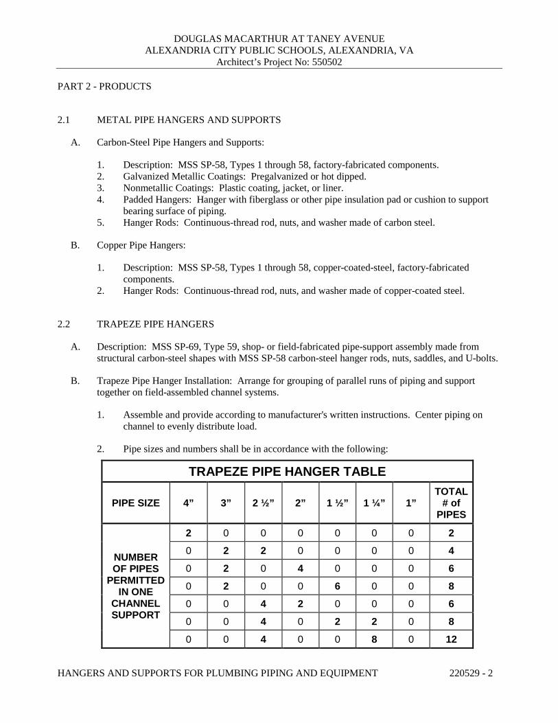
DOUGLAS MACARTHUR AT TANEY AVENUE ALEXANDRIA CITY PUBLIC SCHOOLS, ALEXANDRIA, VA
Architect’s Project No: 550502
HANGERS AND SUPPORTS FOR PLUMBING PIPING AND EQUIPMENT 220529 - 2
PART 2 - PRODUCTS
2.1 METAL PIPE HANGERS AND SUPPORTS
A. Carbon-Steel Pipe Hangers and Supports:
1. Description: MSS SP-58, Types 1 through 58, factory-fabricated components.2. Galvanized Metallic Coatings: Pregalvanized or hot dipped.3. Nonmetallic Coatings: Plastic coating, jacket, or liner.4. Padded Hangers: Hanger with fiberglass or other pipe insulation pad or cushion to support
bearing surface of piping.5. Hanger Rods: Continuous-thread rod, nuts, and washer made of carbon steel.
B. Copper Pipe Hangers:
1. Description: MSS SP-58, Types 1 through 58, copper-coated-steel, factory-fabricatedcomponents.
2. Hanger Rods: Continuous-thread rod, nuts, and washer made of copper-coated steel.
2.2 TRAPEZE PIPE HANGERS
A. Description: MSS SP-69, Type 59, shop- or field-fabricated pipe-support assembly made fromstructural carbon-steel shapes with MSS SP-58 carbon-steel hanger rods, nuts, saddles, and U-bolts.
B. Trapeze Pipe Hanger Installation: Arrange for grouping of parallel runs of piping and supporttogether on field-assembled channel systems.
1. Assemble and provide according to manufacturer's written instructions. Center piping onchannel to evenly distribute load.
2. Pipe sizes and numbers shall be in accordance with the following:
TRAPEZE PIPE HANGER TABLE
PIPE SIZE 4” 3” 2 ½” 2” 1 ½” 1 ¼” 1” TOTAL
# of PIPES
NUMBER OF PIPES
PERMITTED IN ONE
CHANNEL SUPPORT
2 0 0 0 0 0 0 2 0 2 2 0 0 0 0 4 0 2 0 4 0 0 0 6 0 2 0 0 6 0 0 8 0 0 4 2 0 0 0 6 0 0 4 0 2 2 0 8 0 0 4 0 0 8 0 12
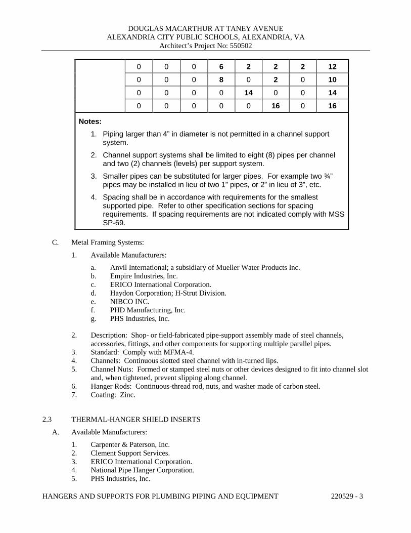
DOUGLAS MACARTHUR AT TANEY AVENUE ALEXANDRIA CITY PUBLIC SCHOOLS, ALEXANDRIA, VA
Architect’s Project No: 550502
HANGERS AND SUPPORTS FOR PLUMBING PIPING AND EQUIPMENT 220529 - 3
0 0 0 6 2 2 2 12 0 0 0 8 0 2 0 10 0 0 0 0 14 0 0 14 0 0 0 0 0 16 0 16
Notes: 1. Piping larger than 4” in diameter is not permitted in a channel support
system. 2. Channel support systems shall be limited to eight (8) pipes per channel
and two (2) channels (levels) per support system. 3. Smaller pipes can be substituted for larger pipes. For example two ¾”
pipes may be installed in lieu of two 1” pipes, or 2” in lieu of 3”, etc. 4. Spacing shall be in accordance with requirements for the smallest
supported pipe. Refer to other specification sections for spacing requirements. If spacing requirements are not indicated comply with MSS SP-69.
C. Metal Framing Systems:
1. Available Manufacturers:
a. Anvil International; a subsidiary of Mueller Water Products Inc. b. Empire Industries, Inc. c. ERICO International Corporation. d. Haydon Corporation; H-Strut Division. e. NIBCO INC. f. PHD Manufacturing, Inc. g. PHS Industries, Inc.
2. Description: Shop- or field-fabricated pipe-support assembly made of steel channels, accessories, fittings, and other components for supporting multiple parallel pipes.
3. Standard: Comply with MFMA-4. 4. Channels: Continuous slotted steel channel with in-turned lips. 5. Channel Nuts: Formed or stamped steel nuts or other devices designed to fit into channel slot
and, when tightened, prevent slipping along channel. 6. Hanger Rods: Continuous-thread rod, nuts, and washer made of carbon steel. 7. Coating: Zinc.
2.3 THERMAL-HANGER SHIELD INSERTS
A. Available Manufacturers:
1. Carpenter & Paterson, Inc. 2. Clement Support Services. 3. ERICO International Corporation. 4. National Pipe Hanger Corporation. 5. PHS Industries, Inc.
DOUGLAS MACARTHUR AT TANEY AVENUE ALEXANDRIA CITY PUBLIC SCHOOLS, ALEXANDRIA, VA
Architect’s Project No: 550502
HANGERS AND SUPPORTS FOR PLUMBING PIPING AND EQUIPMENT 220529 - 4
6. Pipe Shields, Inc.; a subsidiary of Piping Technology & Products, Inc. 7. Piping Technology & Products, Inc. 8. Rilco Manufacturing Co., Inc. 9. Value Engineered Products, Inc.
B. Insulation-Insert Material for Cold Piping: ASTM C 552, Type II cellular glass with 100-psig or ASTM C 591, Type VI, Grade 1 polyisocyanurate with 125-psig minimum compressive strength and vapor barrier.
C. Insulation-Insert Material for Hot Piping: Water-repellent treated, ASTM C 533, Type I calcium silicate with 100-psig, ASTM C 552, Type II cellular glass with 100-psig, or ASTM C 591, Type VI, Grade 1 polyisocyanurate with 125-psig minimum compressive strength.
D. For Trapeze or Clamped Systems: Insert and shield shall cover entire circumference of pipe.
E. For Clevis or Band Hangers: Insert and shield shall cover lower 180 degrees of pipe.
F. Insert Length: Extend 2” beyond sheet metal shield for piping operating below ambient air temperature.
2.4 PIPE STANDS
A. General Requirements for Pipe Stands: Shop- or field-fabricated assemblies made of manufactured corrosion-resistant components to support roof-mounted piping.
1. Available Manufacturers:
a. Cooper B-Line – Dura-Blok b. MAPA Products c. Mifab, Inc. – C-Port d. Miro Industries, Inc. e. OMG, Inc. f. PHP Systems/Design g. Pipe Prop h. Roof Top Blox
2. Provide pipe supports for supporting gas, condensate, refrigeration lines, or hydronic piping on flat roof surfaces. Support shall rest on roof surface without penetrating the roof surface. Supports for condensate piping shall be adjustable vertically to ensure pipe slopes as required.
B. Compact Pipe Stand: One-piece plastic unit with integral-rod roller, pipe clamps, or V-shaped cradle to support pipe, for roof installation without membrane penetration.
C. Curb Mounted Pipe Stands: Shop- or field-fabricated pipe supports made from structural-steel shapes, continuous-thread rods, and rollers, for mounting on permanent stationary roof curb.
DOUGLAS MACARTHUR AT TANEY AVENUE ALEXANDRIA CITY PUBLIC SCHOOLS, ALEXANDRIA, VA
Architect’s Project No: 550502
HANGERS AND SUPPORTS FOR PLUMBING PIPING AND EQUIPMENT 220529 - 5
2.5 EQUIPMENT SUPPORTS
A. Description: Welded, shop or field fabricated equipment support made from structural carbon-steelshapes unless indicated otherwise.
2.6 MISCELLANEOUS MATERIALS
A. Structural Steel: ASTM A 36/A 36M, carbon-steel plates, shapes, and bars; black and galvanized.
B. Grout: ASTM C 1107, factory-mixed and -packaged, dry, hydraulic-cement, non-shrink andnonmetallic grout; suitable for interior and exterior applications.
1. Properties: Non-staining, noncorrosive, and nongaseous.2. Design Mix: 5000-psi, 28-day compressive strength.
PART 3 - EXECUTION
3.1 HANGER AND SUPPORT INSTALLATION
A. Metal Pipe-Hanger Installation: Comply with MSS SP-69 and MSS SP-89. Provide hangers,supports, clamps, and attachments as required to properly support piping from the buildingstructure.
B. Metal Trapeze Pipe-Hanger Installation: Comply with MSS SP-69, MSS SP-89, and Table above.Arrange for grouping of parallel runs of horizontal piping, and support together on field-fabricatedtrapeze pipe hangers.
C. Metal Framing System Installation: Arrange for grouping of parallel runs of piping, and supporttogether on field-assembled metal framing systems.
D. Thermal-Hanger Shield Installation: Provide in pipe hanger or shield for insulated piping.
E. Pipe Stand Installation: Assemble components and mount on smooth roof surface. Do notpenetrate roof membrane.
F. Provide hangers and supports complete with necessary attachments, inserts, bolts, rods, nuts,washers, and other accessories.
G. Equipment Support Installation: Fabricate from welded-structural-steel shapes.
H. Provide hangers and supports to allow controlled thermal and seismic movement of piping systems,to permit freedom of movement between pipe anchors, and to facilitate action of expansion joints,expansion loops, expansion bends, and similar units.
I. Provide lateral bracing with pipe hangers and supports to prevent swaying.

DOUGLAS MACARTHUR AT TANEY AVENUE ALEXANDRIA CITY PUBLIC SCHOOLS, ALEXANDRIA, VA
Architect’s Project No: 550502
HANGERS AND SUPPORTS FOR PLUMBING PIPING AND EQUIPMENT 220529 - 6
J. Provide building attachments within concrete slabs or attach to structural steel. Building attachments may not used on steel joists unless otherwise indicated. Provide additional attachments at concentrated loads, including valves, flanges, and strainers, 2-1/2” and larger and at changes in direction of piping. Provide concrete inserts before concrete is placed; fasten inserts to forms and provide reinforcing bars through openings at top of inserts.
K. Load Distribution: Provide hangers and supports so that piping live and dead loads and stresses from movement will not be transmitted to connected equipment.
L. Pipe Slopes: Provide hangers and supports to provide indicated pipe slopes and to not exceed maximum pipe deflections allowed by ASME B31.9 for building services piping.
M. Insulated Piping:
1. Attach clamps and spacers to piping.
a. Piping Operating above Ambient Air Temperature: Clamp may project through insulation.
b. Piping Operating below Ambient Air Temperature: Provide thermal-hanger shield insert with clamp sized to match OD of insert.
c. Do not exceed pipe stress limits allowed by ASME B31.9 for building services piping.
2. Provide MSS SP-58, Type 39, protection saddles if insulation without vapor barrier is indicated. Fill interior voids with insulation that matches adjoining insulation.
3. Provide MSS SP-58, Type 40, protective shields on cold piping with vapor barrier. Shields shall span an arc of 180 degrees.
4. Shield Dimensions for Pipe: Not less than the following:
a. Pipe ¼” to 3-½”: 12 inches long and 0.048 inch thick. b. Pipe 4”: 12 inches long and 0.06 inch thick. c. Pipe 5” and 6”: 18 inches long and 0.06 inch thick. d. Pipe 8” to 14”: 24 inches long and 0.075 inch thick.
5. Pipes 8” and Larger: Include wood or reinforced calcium-silicate-insulation inserts of length at least as long as protective shield.
6. Thermal-Hanger Shields: Provide with insulation same thickness as piping insulation.
3.2 EQUIPMENT SUPPORTS
A. Fabricate structural-steel stands to suspend equipment from structure overhead or to support equipment above floor.
B. Grouting: Place grout under supports for equipment and make bearing surface smooth.
C. Provide lateral bracing, to prevent swaying, for equipment supports.
3.3 METAL FABRICATIONS
A. Cut, drill, and fit miscellaneous metal fabrications for trapeze pipe hangers and equipment supports.
DOUGLAS MACARTHUR AT TANEY AVENUE ALEXANDRIA CITY PUBLIC SCHOOLS, ALEXANDRIA, VA
Architect’s Project No: 550502
HANGERS AND SUPPORTS FOR PLUMBING PIPING AND EQUIPMENT 220529 - 7
B. Fit exposed connections together to form hairline joints. Field weld connections that cannot be shop welded because of shipping size limitations.
C. Field Welding: Comply with AWS D1.1/D1.1M procedures for shielded, metal arc welding; appearance and quality of welds; and methods used in correcting welding work; and with the following:
1. Provide materials and methods that minimize distortion and develop strength and corrosion resistance of base metals.
2. Obtain fusion without undercut or overlap. 3. Remove welding flux immediately. 4. Finish welds at exposed connections so no roughness shows after finishing and so contours of
welded surfaces match adjacent contours.
3.4 ADJUSTING
A. Hanger Adjustments: Adjust hangers to distribute loads equally on attachments and to achieve indicated slope of pipe.
B. Trim excess length of continuous-thread hanger and support rods to 1-1/2 inches.
3.5 PAINTING
A. Touchup: Unless otherwise indicated clean field welds and abraded areas of shop paint. Paint exposed areas immediately after erecting hangers and supports. Provide same materials as used for shop painting. Comply with SSPC-PA 1 requirements for touching up field-painted surfaces.
1. Apply paint by brush or spray to provide a minimum dry film thickness of 2.0 mils.
B. Galvanized Surfaces: Clean welds, bolted connections, and abraded areas and immediately apply galvanizing-repair paint. Paint shall comply with ASTM A 780.
3.6 HANGER AND SUPPORT SCHEDULE
A. Specific hanger and support requirements are in Sections specifying piping systems and equipment.
B. Comply with MSS SP-69 for pipe-hanger selections and applications that are not specified in piping system Sections.
C. Provide hangers and supports with galvanized metallic coatings for piping and equipment that will not have field-applied finish.
D. Provide nonmetallic coatings on attachments for electrolytic protection where attachments are in direct contact with copper tubing.
E. Provide copper-plated pipe hangers and copper attachments for copper piping and tubing.
F. Provide padded hangers for piping that is subject to scratching.
DOUGLAS MACARTHUR AT TANEY AVENUE ALEXANDRIA CITY PUBLIC SCHOOLS, ALEXANDRIA, VA
Architect’s Project No: 550502
HANGERS AND SUPPORTS FOR PLUMBING PIPING AND EQUIPMENT 220529 - 8
G. Provide thermal-hanger shield inserts for insulated piping and tubing.
H. Horizontal-Piping Hangers and Supports: Unless otherwise indicated provide the following:
1. Adjustable, Steel Clevis Hangers (MSS Type 1): For suspension of stationary pipes ½” to 30”.
2. Yoke-Type Pipe Clamps (MSS Type 2): For suspension of up to 1050 deg F pipes 4” to 14”, requiring up to 4“ of insulation.
3. Carbon- or Alloy-Steel, Double-Bolt Pipe Clamps (MSS Type 3): For suspension of pipes ¾” to 14”, requiring clamp flexibility and up to 4 inches of insulation.
4. Steel Pipe Clamps (MSS Type 4): For suspension of cold and hot pipes ½” to 14” if little or no insulation is required.
5. Pipe Hangers (MSS Type 5): For suspension of pipes ½” to 4”, to allow off-center closure for hanger installation before pipe erection.
6. Adjustable, Swivel Split- or Solid-Ring Hangers (MSS Type 6): For suspension of noninsulated, stationary pipes ¾” to 8”.
7. Adjustable, Steel Band Hangers (MSS Type 7): For suspension of noninsulated, stationary pipes ½” to 8”.
8. Adjustable Band Hangers (MSS Type 9): For suspension of noninsulated, stationary pipes ½” to 8”.
9. Adjustable, Swivel-Ring Band Hangers (MSS Type 10): For suspension of noninsulated, stationary pipes ½” to 8”.
10. Split Pipe Ring with or without Turnbuckle Hangers (MSS Type 11): For suspension of noninsulated, stationary pipes ½” to 8”.
11. Extension Hinged or Two-Bolt Split Pipe Clamps (MSS Type 12): For suspension of noninsulated, stationary pipes NPS ½” to 3”.
12. U-Bolts (MSS Type 24): For support of heavy pipes ½” to 14”. 13. Clips (MSS Type 26): For support of insulated pipes not subject to expansion or contraction. 14. Pipe Saddle Supports (MSS Type 36): For support of pipes 4” to 14”, with steel-pipe base
stanchion support and cast-iron floor flange or carbon-steel plate. 15. Pipe Stanchion Saddles (MSS Type 37): For support of pipes 4” to 14”, with steel-pipe base
stanchion support and cast-iron floor flange or carbon-steel plate, and with U-bolt to retain pipe.
16. Adjustable Pipe Saddle Supports (MSS Type 38): For stanchion-type support for pipes 2-½” to 14” if vertical adjustment is required, with steel-pipe base stanchion support and cast-iron floor flange.
17. Single-Pipe Rolls (MSS Type 41): For suspension of pipes 1” to 14”, from two rods if longitudinal movement caused by expansion and contraction might occur.
18. Adjustable Roller Hangers (MSS Type 43): For suspension of pipes 2-½” to 14”, from single rod if horizontal movement caused by expansion and contraction might occur.
19. Complete Pipe Rolls (MSS Type 44): For support of pipes 2” to 14” if longitudinal movement caused by expansion and contraction might occur but vertical adjustment is not necessary.
20. Pipe Roll and Plate Units (MSS Type 45): For support of pipes 2” to 14” if small horizontal movement caused by expansion and contraction might occur and vertical adjustment is not necessary.
21. Adjustable Pipe Roll and Base Units (MSS Type 46): For support of pipes 2” to 14”if vertical and lateral adjustment during installation might be required in addition to expansion and contraction.
DOUGLAS MACARTHUR AT TANEY AVENUE ALEXANDRIA CITY PUBLIC SCHOOLS, ALEXANDRIA, VA
Architect’s Project No: 550502
HANGERS AND SUPPORTS FOR PLUMBING PIPING AND EQUIPMENT 220529 - 9
I. Vertical-Piping Clamps: Unless otherwise indicated provide the following:
1. Extension Pipe or Riser Clamps (MSS Type 8): For support of pipe risers ¾” to 14”.2. Carbon- or Alloy-Steel Riser Clamps (MSS Type 42): For support of pipe risers ¾” to 14” if
longer ends are required for riser clamps.
J. Hanger-Rod Attachments: Unless otherwise indicated provide the following:
1. Steel Turnbuckles (MSS Type 13): For adjustment up to 6 inches for heavy loads.2. Steel Clevises (MSS Type 14): For 120 to 450 deg F piping installations.3. Swivel Turnbuckles (MSS Type 15): For use with MSS Type 11, split pipe rings.4. Malleable-Iron Sockets (MSS Type 16): For attaching hanger rods to various types of
building attachments.5. Steel Weldless Eye Nuts (MSS Type 17): For 120 to 450 deg F piping installations.6. Flat Plate, Double Nut, and Washer as Detailed on Structural Drawings: For attaching to bar
joists. Method of attachment to bar joists must be approved by the structural engineer andjoist manufacturer.
K. Building Attachments: Unless otherwise indicated provide the following:
1. Steel or Malleable Concrete Inserts (MSS Type 18): For upper attachment to suspend pipehangers from concrete ceiling.
2. Flat Plate, Double Nuts, and Washer as Detailed on Structural Drawings: For use under roofinstallations with bar-joist construction to attach to bottom chord of joist.
3. Side-Beam or Channel Clamps (MSS Type 20): For attaching to bottom flange of beams,channels, or angles.
4. Center-Beam Clamps (MSS Type 21): For attaching to center of bottom flange of beams.5. Welded Beam Attachments (MSS Type 22): For attaching to bottom of beams if loads are
considerable and rod sizes are large.6. C-Clamps (MSS Type 23): For structural shapes.7. Top-Beam Clamps (MSS Type 25): For top of beams if hanger rod is required tangent to
flange edge.8. Side-Beam Clamps (MSS Type 27): For bottom of steel I-beams.9. Steel-Beam Clamps with Eye Nuts (MSS Type 28): For attaching to bottom of steel I-beams
for heavy loads.10. Linked-Steel Clamps with Eye Nuts (MSS Type 29): For attaching to bottom of steel I-
beams for heavy loads, with link extensions.11. Malleable-Beam Clamps with Extension Pieces (MSS Type 30): For attaching to structural
steel.12. Welded-Steel Brackets: For support of pipes from below or for suspending from above by
using clip and rod. Provide one of the following for indicated loads:
a. Light (MSS Type 31): 750 lb.b. Medium (MSS Type 32): 1500 lb.c. Heavy (MSS Type 33): 3000 lb.
13. Side-Beam Brackets (MSS Type 34): For sides of steel or wooden beams.14. Plate Lugs (MSS Type 57): For attaching to steel beams if flexibility at beam is required.15. Horizontal Travelers (MSS Type 58): For supporting piping systems subject to linear
horizontal movement where headroom is limited.
DOUGLAS MACARTHUR AT TANEY AVENUE ALEXANDRIA CITY PUBLIC SCHOOLS, ALEXANDRIA, VA
Architect’s Project No: 550502
HANGERS AND SUPPORTS FOR PLUMBING PIPING AND EQUIPMENT 220529 - 10
L. Saddles and Shields: Unless otherwise indicated provide the followings:
1. Steel-Pipe-Covering Protection Saddles (MSS Type 39): To fill interior voids with insulation that matches adjoining insulation.
2. Protection Shields (MSS Type 40): Of length recommended in writing by manufacturer to prevent crushing insulation.
3. Thermal-Hanger Shield Inserts: For supporting insulated pipe.
M. Spring Hangers and Supports: Unless otherwise indicated provide the following:
1. Restraint-Control Devices (MSS Type 47): To control pipe movement. 2. Spring Cushions (MSS Type 48): For light loads if vertical movement does not exceed 1-1/4
inches. 3. Spring-Cushion Roll Hangers (MSS Type 49): For equipping Type 41, roll hanger with
springs. 4. Spring Sway Braces (MSS Type 50): To retard sway, shock, vibration, or thermal expansion
in piping systems. 5. Variable-Spring Hangers (MSS Type 51): Preset to indicated load and limit variability factor
to 25 percent to allow expansion and contraction of piping system from hanger. 6. Variable-Spring Base Supports (MSS Type 52): Preset to indicated load and limit variability
factor to 25 percent to allow expansion and contraction of piping system from base support. 7. Variable-Spring Trapeze Hangers (MSS Type 53): Preset to indicated load and limit
variability factor to 25 percent to allow expansion and contraction of piping system from trapeze support.
8. Constant Supports: For critical piping stress and if necessary to avoid transfer of stress from one support to another support, critical terminal, or connected equipment. Include auxiliary stops for erection, hydrostatic test, and load-adjustment capability. These supports include the following types:
a. Horizontal (MSS Type 54): Mounted horizontally. b. Vertical (MSS Type 55): Mounted vertically. c. Trapeze (MSS Type 56): Two vertical-type supports and one trapeze member.
N. Comply with MSS SP-69 for trapeze pipe-hanger selections and applications that are not specified in piping system Sections.
O. Comply with MFMA-103 for metal framing system selections and applications that are not specified in piping system Sections.
P. Provide powder-actuated fasteners or mechanical-expansion anchors instead of building attachments where indicated in concrete construction.
END OF SECTION 220529
DOUGLAS MACARTHUR AT TANEY AVENUE ALEXANDRIA CITY PUBLIC SCHOOLS, ALEXANDRIA, VA
Architect’s Project No: 550502
IDENTIFICATION FOR PLUMBING PIPING AND EQUIPMENT 220553-1
SECTION 220553 - IDENTIFICATION FOR PLUMBING PIPING AND EQUIPMENT
PART 1 - GENERAL
1.1 RELATED DOCUMENTS
A. Provisions of the Contract and of the Contract Documents apply to this Section.
1.2 SUBMITTALS
A. Product Data: For each type of product indicated.
B. Equipment Label Schedule: Include a listing of all equipment to be labeled with the proposedcontent for each label.
C. Valve Schedules: For each piping system to include in maintenance manuals.
D. 1/16”=1’-0” scale drawing showing all valve locations to include in maintenance manuals.
1.3 QUALITY ASSURANCE
A. ASME Compliance: Comply with ASME A13.1, "Scheme for the Identification of PipingSystems," for letter size, length of color field, colors, and viewing angles of identificationdevices for piping.
1.4 COORDINATION
A. Coordinate installation of identifying devices with completion of covering and painting ofsurfaces where devices are to be applied.
B. Coordinate installation of identifying devices with locations of access panels and doors.
C. Install identifying devices before installing acoustical ceilings and similar concealment.
PART 2 - PRODUCTS
2.1 EQUIPMENT LABELS
A. Metal Labels for Equipment:
1. Material and Thickness: Brass, Aluminum, or anodized aluminum, 0.032-inch minimumthickness, and having predrilled or stamped holes for attachment hardware.
2. Minimum Label Size: Length and width vary for required label content, but not less than2-1/2 by 3/4 inch.
DOUGLAS MACARTHUR AT TANEY AVENUE ALEXANDRIA CITY PUBLIC SCHOOLS, ALEXANDRIA, VA
Architect’s Project No: 550502
IDENTIFICATION FOR PLUMBING PIPING AND EQUIPMENT 220553-2
3. Minimum Letter Size: 1/4 inch for name of units if viewing distance is less than 24 inches, 1/2 inch for viewing distances up to 72 inches, and proportionately larger lettering for greater viewing distances. Include secondary lettering two-thirds to three-fourths the size of principal lettering.
4. Fasteners: Stainless-steel rivets or self-tapping screws. 5. Adhesive: Contact-type permanent adhesive, compatible with label and with substrate.
B. Plastic Labels for Equipment:
1. Material and Thickness: Multilayer, multicolor, plastic labels for mechanical engraving, 1/16 inch thick, and having predrilled holes for attachment hardware.
2. Letter Color: White. 3. Background Color: Black. 4. Maximum Temperature: Able to withstand temperatures up to 160 deg F. 5. Minimum Label Size: Length and width vary for required label content, but not less than
2-1/2 by 3/4 inch. 6. Minimum Letter Size: 1/4 inch for name of units if viewing distance is less than 24
inches, 1/2 inch for viewing distances up to 72 inches, and proportionately larger lettering for greater viewing distances. Include secondary lettering two-thirds to three-fourths the size of principal lettering.
7. Fasteners: Stainless-steel rivets or self-tapping screws. 8. Adhesive: Contact-type permanent adhesive, compatible with label and with substrate.
C. Label Content: Include equipment's Drawing designation or unique equipment number, Drawing numbers where equipment is indicated (plans, details, and schedules), plus the Specification Section number and title where equipment is specified.
D. Equipment Label Schedule: For each item of equipment to be labeled, on 8-1/2-by-11-inch bond paper. Tabulate equipment identification number and identify Drawing numbers where equipment is indicated (plans, details, and schedules), plus the Specification Section number and title where equipment is specified. Equipment schedule shall be included in operation and maintenance data.
2.2 WARNING SIGNS AND LABELS
A. Material and Thickness: Multilayer, multicolor, plastic labels for mechanical engraving, 1/16 inch thick, and having predrilled holes for attachment hardware.
B. Letter Color: White.
C. Background Color: Red.
D. Maximum Temperature: Able to withstand temperatures up to 160 deg F.
E. Minimum Label Size: Length and width vary for required label content, but not less than 2-1/2 by 3/4 inch.
DOUGLAS MACARTHUR AT TANEY AVENUE ALEXANDRIA CITY PUBLIC SCHOOLS, ALEXANDRIA, VA
Architect’s Project No: 550502
IDENTIFICATION FOR PLUMBING PIPING AND EQUIPMENT 220553-3
F. Minimum Letter Size: 1/4 inch for name of units if viewing distance is less than 24 inches, 1/2 inch for viewing distances up to 72 inches, and proportionately larger lettering for greater viewing distances. Include secondary lettering two-thirds to three-fourths the size of principal lettering.
G. Fasteners: Stainless-steel rivets or self-tapping screws.
H. Adhesive: Contact-type permanent adhesive, compatible with label and with substrate.
I. Label Content: Include caution and warning information, plus emergency notification instructions.
2.3 PIPE LABELS
A. General Requirements for Manufactured Pipe Labels: Preprinted, color-coded, with lettering indicating service, and showing flow direction.
B. Pretensioned Pipe Labels: Precoiled, semirigid plastic formed to cover full circumference of pipe and to attach to pipe without fasteners or adhesive.
C. Self-Adhesive Pipe Labels: Printed plastic with contact-type, permanent-adhesive backing.
D. Pipe Label Contents: Include identification of piping service using same designations or abbreviations as used on Drawings, pipe size, and an arrow indicating flow direction.
1. Flow-Direction Arrows: Integral with piping system service lettering to accommodate both directions, or as separate unit on each pipe label to indicate flow direction.
2. Lettering Size: At least 1-1/2 inches high.
2.4 STENCILS
A. Stencils: Prepared with letter sizes according to ASME A13.1 for piping; minimum letter height of 1-1/4 inches for ducts; and minimum letter height of 3/4 inch for access panel and door markers, equipment markers, equipment signs, and similar operational instructions.
1. Stencil Material: Metal or fiberboard.
2. Stencil Paint: Exterior, gloss, black, unless otherwise indicated. Paint shall be low VOC and shall meet the requirements of section 09910. Paint may be in pressurized spray-can form.
3. Identification Paint: Exterior, in colors according to ASME A13.1, unless otherwise indicated. Paint shall be low VOC and shall meet the requirements of section 09910.
2.5 VALVE TAGS
A. Valve Tags: Stamped or engraved with 1/4-inch letters for piping system abbreviation and 1/2-inch numbers, numbering scheme approved by Architect. Provide 5/32-inch hole for fastener.
1. Material: 0.032-inch- thick brass or
DOUGLAS MACARTHUR AT TANEY AVENUE ALEXANDRIA CITY PUBLIC SCHOOLS, ALEXANDRIA, VA
Architect’s Project No: 550502
IDENTIFICATION FOR PLUMBING PIPING AND EQUIPMENT 220553-4
2. Material: 0.0375-inch- thick stainless steel or
3. Material: 3/32-inch- thick laminated plastic with 2 black surfaces and white inner layer.
B. Valve-Tag Fasteners: Brass wire-link or beaded chain; or S-hook.
2.6 VALVE SCHEDULES
A. Valve Schedules: For each piping system, on standard-size bond paper. Tabulate valve number, piping system, system abbreviation (as shown on valve tag), location of valve (room or space), normal-operating position (open, closed, or modulating), and variations for identification. Mark valves for emergency shutoff and similar special uses.
1. Valve-Schedule Frames: Glazed display frame for removable mounting on masonry walls for each page of valve schedule. Include mounting screws and hangers.
2. Frame: Finished hardwood or extruded aluminum.
3. Glazing: ASTM C 1036, Type I, Class 1, Glazing Quality B, 2.5-mm, single-thickness glass.
2.7 VALVE PLAN
A. Valve Plan: Prepare a scale drawing. Provide the location and identity of each valve.
1. Valve Plan Frames: Glazed display frame for removable mounting on masonry walls for each page of valve plan. Include mounting screws and hangers.
2. Frame: Finished hardwood or extruded aluminum.
3. Glazing: ASTM C 1036, Type I, Class 1, Glazing Quality B, 2.5-mm, single-thickness glass.
2.8 WARNING TAGS
A. Warning Tags: Preprinted or partially preprinted, accident-prevention tags, of plasticized card stock with matte finish suitable for writing.
1. Size: 3 by 5-1/4 inches minimum. 2. Fasteners: Brass grommet and wire. 3. Nomenclature: Large-size primary caption such as "DANGER," "CAUTION," or "DO
NOT OPERATE." 4. Color: Yellow background with black lettering.
DOUGLAS MACARTHUR AT TANEY AVENUE ALEXANDRIA CITY PUBLIC SCHOOLS, ALEXANDRIA, VA
Architect’s Project No: 550502
IDENTIFICATION FOR PLUMBING PIPING AND EQUIPMENT 220553-5
PART 3 - EXECUTION
3.1 PREPARATION
A. Clean piping and equipment surfaces of substances that could impair bond of identification devices, including dirt, oil, grease, release agents, and incompatible primers, paints, and encapsulants.
3.2 EQUIPMENT LABEL INSTALLATION
A. Install and permanently fasten equipment nameplates on each major item of plumbing equipment that does not have nameplate, or has a nameplate that is damaged or located where not easily visible. Locate nameplates where easily visible. Include nameplates for the following general categories of equipment:
1. Fuel-burning units.
2. Pumps, compressors, and other motor-driven equipment.
3. Heat exchangers and similar equipment.
4. Water heaters and storage tanks.
B. Install equipment markers with permanent adhesive on or near each major item of mechanical equipment. Data required for markers may be included on signs, and markers may be omitted if both are indicated.
1. Letter Size: Minimum 1/4 inch for name of units if viewing distance is less than 24 inches, 1/2 inch for viewing distances up to 72 inches, and proportionately larger lettering for greater viewing distances. Include secondary lettering two-thirds to three-fourths the size of principal lettering.
2. Data: Distinguish among multiple units, indicate operational requirements, indicate safety and emergency precautions, warn of hazards and improper operations, and identify units.
3. Locate markers where accessible and visible. Include markers for the following general categories of equipment:
a. Main control and operating valves, including safety devices and hazardous units such as gas outlets.
b. Meters, gages, and thermometers. c. Fuel-burning units. d. Pumps, compressors, and other motor-driven equipment. e. Heat exchangers and similar equipment. f. Water heaters and storage tanks.
C. Stenciled Equipment Marker Option: Stenciled markers may be provided instead of laminated-plastic equipment markers, at Installer's option, if lettering larger than 1 inch high is needed for proper identification because of distance from normal location of required identification.
D. Install equipment signs with screws or permanent adhesive on or near each major item of mechanical equipment. Locate signs where easily visible.
DOUGLAS MACARTHUR AT TANEY AVENUE ALEXANDRIA CITY PUBLIC SCHOOLS, ALEXANDRIA, VA
Architect’s Project No: 550502
IDENTIFICATION FOR PLUMBING PIPING AND EQUIPMENT 220553-6
1. Identify mechanical equipment with equipment markers in the following color codes:
a. Green: For cooling equipment and components. b. Yellow: For heating equipment and components. c. Orange: For combination cooling and heating equipment and components. d. Brown: For energy-reclamation equipment and components. e. Blue: For equipment not listed in a through d
2. Letter Size: Minimum 1/4 inch for name of units if viewing distance is less than 24 inches, 1/2 inch for viewing distances up to 72 inches, and proportionately larger lettering for greater viewing distances. Include secondary lettering two-thirds to three-fourths the size of principal lettering.
3. Data: Distinguish among multiple units, indicate operational requirements, indicate safety and emergency precautions, warn of hazards and improper operations, and identify units.
E. Stenciled Equipment Sign Option: Stenciled signs may be provided instead of laminated-plastic equipment signs, at Installer's option, if lettering larger than 1 inch high is needed for proper identification because of distance from normal location of required identification.
F. Install access panel markers with screws on equipment access panels.
3.3 PIPE LABEL INSTALLATION
A. Piping Color-Coding: Painting of piping is specified in other sections.
B. Stenciled Pipe Label Option: Stenciled labels may be provided instead of manufactured pipe labels, at Installer's option. Install stenciled pipe labels with painted, color-coded bands or rectangles on each piping system.
1. Identification Paint: Use for contrasting background. 2. Stencil Paint: Use for pipe marking.
C. Locate pipe labels where piping is exposed or above accessible ceilings in finished spaces; machine rooms; accessible maintenance spaces such as shafts, tunnels, and plenums; and exterior exposed locations as follows:
1. Near each valve and control device. 2. Near each branch connection, excluding short takeoffs for fixtures and terminal units.
Where flow pattern is not obvious, mark each pipe at branch. 3. Near penetrations through walls, floors, ceilings, and inaccessible enclosures. 4. At access doors, manholes, and similar access points that permit view of concealed
piping. 5. Near major equipment items and other points of origination and termination. 6. Spaced at maximum intervals of 25 feet. 7. On piping above removable acoustical ceilings. Omit intermediately spaced labels.
D. Pipe Label Color Schedule:
1. Compressed-Air Piping:
DOUGLAS MACARTHUR AT TANEY AVENUE ALEXANDRIA CITY PUBLIC SCHOOLS, ALEXANDRIA, VA
Architect’s Project No: 550502
IDENTIFICATION FOR PLUMBING PIPING AND EQUIPMENT 220553-7
a. Background Color: Black.b. Letter Color: White.
2. Domestic Cold Water Piping:
a. Background Color: Green.b. Letter Color: White.
3. Domestic Hot Water Piping:
a. Background Color: Green.b. Letter Color: White.
4. Sanitary Waste and Storm Drainage Piping:
a. Background Color: Green.b. Letter Color: White.
3.4 VALVE-TAG INSTALLATION
A. Install tags on valves and control devices in piping systems, except check valves; valves withinfactory-fabricated equipment units; plumbing fixture supply stops; shutoff valves; faucets;convenience and lawn-watering hose connections; and HVAC terminal devices and similarroughing-in connections of end-use fixtures and units. List tagged valves in a valve schedule.
B. Valve-Tag Application Schedule: Tag valves according to size, shape, and color scheme andwith captions similar to those indicated in the following:
1. Valve-Tag Size and Shape:
a. Domestic Cold Water: 1 ½”, round.b. Domestic Hot Water: 1 ½”, round.c. Domestic Hot Water Recirculation: 1 ½”, round.d. Natural Gas: 2”, round.
2. Valve-Tag Color:
a. Domestic Cold Water: Blue.b. Domestic Hot Water: Red.c. Domestic Hot Water Recirculation: Red.d. Natural Gas: Yellow.
3. Letter Color:
a. Domestic Cold Water: Black.b. Domestic Hot Water: White.c. Domestic Hot Water Recirculation: White.d. Natural Gas: 2”, Black.
3.5 VALVE SCHEDULE INSTALLATION
A. Mount valve schedules on wall in accessible location in each major equipment room and wheredirected by owner.
DOUGLAS MACARTHUR AT TANEY AVENUE ALEXANDRIA CITY PUBLIC SCHOOLS, ALEXANDRIA, VA
Architect’s Project No: 550502
IDENTIFICATION FOR PLUMBING PIPING AND EQUIPMENT 220553-8
3.6 VALVE PLAN INSTALLATION
A. Mount valve plans on wall in accessible location in each major equipment room and where directed by owner.
3.7 WARNING-TAG INSTALLATION
A. Write required message on, and attach warning tags to, equipment and other items where required.
3.8 ADJUSTING
A. Relocate mechanical identification materials and devices that have become visually blocked by other work.
3.9 CLEANING
A. Clean faces of mechanical identification devices and glass fronts of valve schedules and plans.
END OF SECTION 220553
DOUGLAS MACARTHUR AT TANEY AVENUE ALEXANDRIA CITY PUBLIC SCHOOLS, ALEXANDRIA, VA
Architect’s Project No: 550502
PLUMBING INSULATION 220700 - 1
SECTION 220700 - PLUMBING INSULATION
PART 1 - GENERAL
1.1 RELATED DOCUMENTS
A. Provisions of the Contract and of the Contract Documents apply to this Section.
1.2 DEFINITIONS
A. Outdoor pipe: Pipe located outside the building insulation envelope.
B. Plenum: An unoccupied space or void, on the conditioned side of the building insulation and vapor barrier, being used to return conditioned air to the inlet side of a return or exhaust fan either directly or via a duct connection. An example would be a space with air handling light fixtures or openings in the ceiling used to transport air through the ceiling and then to an open duct located above the ceiling in another location.
C. Indirectly Conditioned Space: A space having no direct conditioning but, due to air movement induced by an exhaust, or return opening, is conditioned by makeup air from an adjacent space. An example would be a small toilet. Boiler rooms, fan rooms, and mechanical rooms do not qualify as indirectly conditioned spaces.
D. Inside the Building Insulation Envelope: For the purposes of this section, boiler rooms, fan rooms, and mechanical rooms are considered to be OUTSIDE the building insulation envelope.
E. Exposed: Visible from any angle without removal of building element or equipment.
F. Concealed: Enclosed in building element or above ceiling such that it is not visible from any angle without removal of building element or equipment.
1.3 SUBMITTALS
A. Product Data: Identify thermal conductivity, thickness, and jackets (both factory and field applied, if any), for each type of product indicated.
B. Shop Drawings: Show fabrication and installation details for the following:
1. Detail application of removable insulation covers. 2. Detail application of protective shields, saddles, and inserts at hangers for each type of
insulation and hanger. 3. Detail attachment and covering of heat tracing inside insulation. 4. Detail insulation application at pipe expansion joints for each type of insulation. 5. Detail insulation application at elbows, fittings, flanges, valves, and specialties for each
type of insulation. 6. Detail removable insulation at piping specialties, equipment connections, and access
panels. 7. Detail application of field-applied jackets. 8. Detail application at linkages of control devices. 9. Detail field application for each equipment type.

DOUGLAS MACARTHUR AT TANEY AVENUE ALEXANDRIA CITY PUBLIC SCHOOLS, ALEXANDRIA, VA
Architect’s Project No: 550502
PLUMBING INSULATION 220700 - 2
1.4 QUALITY ASSURANCE
A. Fire-Test-Response Characteristics: Insulation and related materials shall have fire-test-response characteristics indicated, as determined by testing identical products per ASTM E 84, by a testing and inspecting agency acceptable to authorities having jurisdiction. Factory label insulation and jacket materials and adhesive, mastic, tapes, and cement material containers, with appropriate markings of applicable testing and inspecting agency.
1. Insulation Installed Indoors: Flame-spread index of 25 or less, and smoke-developed index of 50 or less.
2. Insulation Installed Outdoors: Flame-spread index of 75 or less, and smoke-developed index of 150 or less.
1.5 DELIVERY, STORAGE, AND HANDLING
A. Packaging: Ship insulation materials in containers marked by manufacturer with type, grade, and maximum use temperature.
B. Ship Insulated Piping System Components on pallets and wood supports. Securely fasten and protect from damage. Store off the ground and cover with opaque waterproof tarp to protect materials from sunlight and rain.
1.6 COORDINATION
A. Coordinate size and location of supports, hangers, and insulation shields specified in Section "Hangers and Supports for HVAC Piping and Equipment."
B. Coordinate clearance requirements with piping installer for piping insulation, duct installer for duct insulation, and equipment installer for equipment insulation.
C. Maintain clearances required for maintenance.
D. Coordinate installation and testing of heat tracing.
PART 2 - PRODUCTS
2.1 MANUFACTURERS
A. Available Manufacturers:
1. Mineral-Fiber Insulation: a. CertainTeed Manson. b. Johns Manville c. Knauf FiberGlass GmbH. d. Owens-Corning Fiberglas Corp. e. Schuller International, Inc.
2. Flexible Elastomeric Thermal Insulation: a. Armstrong World Industries, Inc. b. Rubatex Corp.
3. Polyolefin Insulation: a. Armstrong World Industries, Inc. b. IMCOA.
4. Closed-Cell Phenolic-Foam Insulation:
DOUGLAS MACARTHUR AT TANEY AVENUE ALEXANDRIA CITY PUBLIC SCHOOLS, ALEXANDRIA, VA
Architect’s Project No: 550502
PLUMBING INSULATION 220700 - 3
a. Kooltherm Insulation Products, Ltd. 5. Removable Insulation Covers:
a. Advance Thermal Corp.
2.2 INSULATION MATERIALS
A. Comply with requirements in Part 3 schedule articles for where insulating materials shall be applied.
B. Products shall not contain asbestos, lead, mercury, or mercury compounds.
C. Products that come in contact with stainless steel shall have a leachable chloride content of less than 50 ppm when tested according to ASTM C 871.
D. Insulation materials for use on austenitic stainless steel shall be qualified as acceptable according to ASTM C 795.
E. Foam insulation materials shall not use CFC or HCFC blowing agents in the manufacturing process.
F. Mineral-Fiber Board: Glass fibers bonded with a thermosetting resin. Comply with ASTM C 612, Type IB, with factory applied FSK Jacket. Meet the requirements of ASTM C 1290, Type III, inorganic glass fibers bonded by a thermosetting resin to maximum service temperature of 250°F. Faced insulation shall not exceed 25 Flame Spread, 50 Smoke Developed when tested in accordance with ASTM E84.
G. Semi-Rigid Mineral-Fiber Board: Glass fibers bonded with a thermosetting resin. Comply with ASTM C 1136, Type I, II, III, & IV with factory applied all-service jacket (ASJ) or Type II, IV with factory applied Foil Scrim Kraft (FSK) jacket.
H. Mineral-Fiber Blanket with Factory Applied FSK Jacket: Meet the requirements of ASTM C 1290, Type III, inorganic glass fibers bonded by a thermosetting resin with a multi-purpose foil-scrim kraft (FSK) jacket to maximum service temperature of 250°F. FSK shall meet the requirements of ASTM C 1136, Type II, when surface burning characteristics are determined in accordance with ASTM E 84 with the foil surface of the material exposed to the flame as it is in the final composite. Composite (insulation, facing and adhesive) shall not exceed 25 Flame Spread, 50 Smoke Developed when tested in accordance with ASTM E 84. Insulation properties shall be as follows:
1. Thickness: 1-1/2” a. Density: 0.75 pcf b. Minimum uncompressed R value: 5.0 c. Minimum installed R value assuming 25% compression: 4.0
2. Thickness: 2” a. Density: 1.0 pcf b. Minimum uncompressed R value: 7.4 c. Minimum installed R value assuming 25% compression: 6.0
3. Alternate to 2” 1.0 pcf: Thickness: 2.2” a. Density: 0.75 pcf b. Minimum uncompressed R value: 7.4 c. Minimum installed R value assuming 25% compression: 6.0
4. Thickness: 3” a. Density: 0.75 pcf
DOUGLAS MACARTHUR AT TANEY AVENUE ALEXANDRIA CITY PUBLIC SCHOOLS, ALEXANDRIA, VA
Architect’s Project No: 550502
PLUMBING INSULATION 220700 - 4
b. Minimum uncompressed R value: 10.0 c. Minimum installed R value assuming 25% compression: 8.3
I. Medium Temperature Mineral-Fiber Blanket for Operating Temperatures from 250 to 850 deg F: Glass fibers bonded with a thermosetting resin. Comply with ASTM C 553, Type II, without facing and with all-service jacket manufactured from kraft paper, reinforcing scrim, aluminum foil, and vinyl film.
J. High Temperature Mineral-Fiber Blanket for Temperatures above 850 deg F: Glass fibers bonded with a thermosetting resin. Comply with ASTM C 553, Type V, without facing and with all-service jacket manufactured from kraft paper, reinforcing scrim, aluminum foil, and vinyl film.
K. Mineral-Fiber Pipe Insulation: Glass fibers bonded with a thermosetting resin complying with the following:
1. Preformed Pipe Insulation: Comply with ASTM C 547, Type 1, with factory-applied, all-purpose, vapor-retarder jacket.
2. Semi-Rigid Mineral-Fiber Board: Glass fibers bonded with a thermosetting resin. Comply with ASTM C 1136, Type I, II, III, IV with factory applied all-service jacket (ASJ) or Type II, IV with factory applied Foil Scrim Kraft (FSK) jacket.
3. Blanket Insulation: Comply with ASTM C 553, Type II, without facing. 4. Mineral-Fiber Insulating Cements: Comply with ASTM C 195. 5. Expanded or Exfoliated Vermiculite Insulating Cements: Comply with ASTM C 196. 6. Mineral-Fiber, Hydraulic-Setting Insulating and Finishing Cement: Comply with
ASTM C 449/C 449M.
L. Flexible Elastomeric: Closed-cell, sponge- or expanded-rubber materials. Comply with ASTM C 534, Type I for tubular materials and Type II for sheet materials.
1. Adhesive: As recommended by insulation material manufacturer. 2. Ultraviolet-Protective Coating: As recommended by insulation manufacturer.
M. Closed-Cell Phenolic-Foam: Block insulation of rigid, expanded, closed-cell structure. Comply with ASTM C 1126, Type II, Grade 1.
N. Prefabricated Thermal Insulating Fitting Covers: Comply with ASTM C 450 for dimensions used in preforming insulation to cover valves, elbows, tees, and flanges.
2.3 FIELD-APPLIED JACKETS
A. General: ASTM C 921, Type 1, unless otherwise indicated.
B. Glass Cloth: Woven glass-fiber fabric, plain weave, minimum 8 ounces per square yard.
C. Foil and Paper Jacket: Laminated, glass-fiber-reinforced, flame-retardant kraft paper and aluminum foil.
D. PVC Jacket: High-impact, ultraviolet-resistant PVC; 20 mils thick; roll stock ready for shop or field cutting and forming.
1. Adhesive: As recommended by insulation material manufacturer. 2. PVC Duct Jacket Color: White or gray. 3. PVC Pipe Jacket Color: Color-code piping jackets based on materials contained within
the piping system.

DOUGLAS MACARTHUR AT TANEY AVENUE ALEXANDRIA CITY PUBLIC SCHOOLS, ALEXANDRIA, VA
Architect’s Project No: 550502
PLUMBING INSULATION 220700 - 5
E. Aluminum Jacket: Deep corrugated sheets manufactured from aluminum alloy complying withASTM B 209, and having an integrally bonded moisture barrier over entire surface in contactwith insulation. Factory cut and rolled to indicated sizes. Comply with ASTM B 209, 3003alloy, H-14 temper.
1. Finish and Thickness: Stucco-embossed finish, 0.016 inch thick.2. Moisture Barrier: 1-mil- thick, heat-bonded polyethylene and kraft paper.3. Elbows: Preformed, 45- and 90-degree, short- and long-radius elbows; same material,
finish, and thickness as jacket.
F. Stainless-Steel Jacket: Deep corrugated sheets of stainless steel complying with ASTM A 666,Type 304 or 316; 0.10 inch thick; and roll stock ready for shop or field cutting and forming toindicated sizes.
1. Moisture Barrier: 1-mil- thick, heat-bonded polyethylene and kraft paper.2. Elbows: Gore type, for 45- and 90-degree elbows in same material, finish, and thickness
as jacket.3. Jacket Bands: Stainless steel, Type 304, 3/4 inch wide.
G. Heavy PVC Pipe Fitting Covers: Factory-fabricated fitting covers manufactured from 30-mil-thick, high-impact, ultraviolet-resistant PVC.
1. Shapes: 45- and 90-degree, short- and long-radius elbows, tees, valves, flanges, reducers,end caps, soil-pipe hubs, traps, mechanical joints, and P-trap and supply covers forlavatories for the disabled.
2. Adhesive: As recommended by insulation material manufacturer.
H. Standard PVC Pipe Fitting Covers: Factory-fabricated fitting covers manufactured from 20-mil- thick, high-impact, ultraviolet-resistant PVC.
1. Shapes: 45- and 90-degree, short- and long-radius elbows, tees, valves, flanges, reducers,end caps, soil-pipe hubs, traps, mechanical joints, and P-trap and supply covers forlavatories for the disabled.
2. Adhesive: As recommended by insulation material manufacturer.
2.4 REMOVABLE INSULATION COVERS
A. Pre-manufactured easily removable insulation cover/blanket intended for insulation ofequipment and devices requiring periodic maintenance.
2.5 ACCESSORIES AND ATTACHMENTS
A. Glass Cloth and Tape: Comply with MIL-C-20079H, Type I for cloth and Type II for tape.Woven glass-fiber fabrics, plain weave, presized a minimum of 8 oz. /sq. yd.
1. Tape Width: 4 inches.
B. Bands: 3/4 inch wide, in one of the following materials compatible with jacket:
1. Stainless Steel: ASTM A 666, Type 304; 0.020 inch thick.2. Galvanized Steel: 0.005 inch thick.3. Aluminum: 0.007 inch thick.4. Brass: 0.010 inch thick.5. Nickel-Copper Alloy: 0.005 inch thick.

DOUGLAS MACARTHUR AT TANEY AVENUE ALEXANDRIA CITY PUBLIC SCHOOLS, ALEXANDRIA, VA
Architect’s Project No: 550502
PLUMBING INSULATION 220700 - 6
C. Wire: 0.080-inch, nickel-copper alloy; 0.062-inch, soft-annealed, stainless steel; or 0.062-inch, soft-annealed, galvanized steel.
D. Weld-Attached Anchor Pins and Washers: Copper-coated steel pin for capacitor-discharge welding and galvanized speed washer. Pin length sufficient for insulation thickness indicated.
1. Welded Pin Holding Capacity: 100 lb for direct pull perpendicular to the attached surface.
E. Adhesive-Attached Anchor Pins and Speed Washers: Galvanized steel plate, pin, and washer manufactured for attachment to duct, pipe, plenum and breeching with adhesive. Pin length sufficient for insulation thickness indicated.
1. Adhesive: Recommended by the anchor pin manufacturer as appropriate for surface temperatures of ducts, pipes, plenums, and breechings; and to achieve a holding capacity of 100 lb. for direct pull perpendicular to the adhered surface.
F. Self-Adhesive Anchor Pins and Speed Washers: Galvanized steel plate, pin, and washer manufactured for attachment to duct, pipe, and plenum with adhesive. Pin length sufficient for insulation thickness indicated.
2.6 VAPOR RETARDERS
A. Mastics: Materials recommended by insulation material manufacturer that are compatible with insulation materials, jackets, and substrates.
2.7 REMOVABLE INSULATION COVERS
A. Pre-manufactured easily removable insulation cover/blanket intended for insulation of equipment and devices requiring periodic maintenance.
PART 3 - EXECUTION
3.1 EXAMINATION
A. Examine substrates and conditions for compliance with requirements for installation and other conditions affecting performance of insulation application.
B. Proceed with installation only after unsatisfactory conditions have been corrected.
3.2 PREPARATION
A. Surface Preparation: Clean and dry surfaces to receive insulation. Remove materials that will adversely affect insulation application.
3.3 GENERAL APPLICATION REQUIREMENTS
A. Apply insulation materials, accessories, and finishes according to the manufacturer's written instructions; with smooth, straight, and even surfaces; and free of voids throughout the length of piping, and fittings.
B. Refer to schedules at the end of this Section for materials, forms, jackets, and thickness required for each system.
DOUGLAS MACARTHUR AT TANEY AVENUE ALEXANDRIA CITY PUBLIC SCHOOLS, ALEXANDRIA, VA
Architect’s Project No: 550502
PLUMBING INSULATION 220700 - 7
C. Use accessories compatible with insulation materials and suitable for the service. Use accessories that do not corrode, soften, or otherwise attack insulation or jacket in either wet or dry state.
D. Apply multiple layers of insulation with seams staggered.
E. Do not weld brackets, clips, or other attachment devices to piping, fittings, and specialties.
F. Seal joints and seams with vapor-retarder mastic on insulation indicated to receive a vapor retarder.
G. Keep insulation materials dry at all times. Insulation that becomes wet or is otherwise damaged beyond repair shall be removed immediately and replaced. Replacement material and installation shall be in accordance with these specifications.
H. Apply insulation with tight longitudinal seams and end joints. Bond seams and joints with adhesive recommended by the insulation material manufacturer.
I. Apply insulation with the minimum number of joints practical.
J. Apply insulation over fittings, valves, and specialties, with continuous thermal and vapor-retarder integrity, unless otherwise indicated.
K. Refer to special instructions for applying insulation over fittings, valves, and specialties.
L. Hangers and Anchors: Where vapor retarder is indicated, seal penetrations in insulation at hangers, supports, anchors, and other projections with vapor-retarder mastic.
1. Apply insulation continuously through hangers and around anchor attachments. 2. For insulation application where vapor retarders are indicated, extend insulation on
anchor legs at least 12 inches from point of attachment to pipe and taper insulation ends. Seal tapered ends with a compound recommended by the insulation material manufacturer to maintain vapor retarder.
3. Install insert materials and apply insulation to tightly join the insert. Seal insulation to insulation inserts with adhesive or sealing compound recommended by the insulation material manufacturer.
4. Cover inserts with jacket material matching adjacent pipe insulation. Install shields over jacket, arranged to protect the jacket from tear or puncture by the hanger, support, and shield.
M. Insulation Terminations: For insulation application where vapor retarders are indicated, seal ends with a compound recommended by the insulation material manufacturer to maintain vapor retarder.
N. Apply insulation with integral jackets as follows:
1. Pull jacket tight and smooth. 2. Joints and Seams: Cover with tape and vapor retarder as recommended by insulation
material manufacturer to maintain vapor seal. 3. Vapor-Retarder Mastics: Where vapor retarders are indicated, apply mastic on seams and
joints and at ends adjacent to pipe joints and fittings.
O. Cut insulation according to manufacturer's written instructions to prevent compressing insulation to less than 75 percent of its nominal thickness.
P. Install vapor-retarder mastic on pipes and equipment.

DOUGLAS MACARTHUR AT TANEY AVENUE ALEXANDRIA CITY PUBLIC SCHOOLS, ALEXANDRIA, VA
Architect’s Project No: 550502
PLUMBING INSULATION 220700 - 8
1. Pipes and equipment with vapor retarders: Overlap insulation facing at seams and seal with vapor-retarder mastic and pressure-sensitive tape having same facing as insulation. Repair punctures, tears, and penetrations with tape or mastic to maintain vapor-retarder seal.
2. Pipes and equipment without vapor retarders: Overlap insulation facing at seams and secure with outward clinching staples and pressure-sensitive tape having same facing as insulation.
Q. Roof Penetrations: Apply insulation for interior applications to a point even with top of roof flashing.
1. Seal penetrations with vapor-retarder mastic. 2. Apply insulation for exterior applications tightly joined to interior insulation ends. 3. Seal insulation to roof flashing with vapor-retarder mastic.
R. Interior Wall and Partition Penetrations: Apply insulation continuously through walls and partitions, except fire-rated walls and partitions.
S. Fire-Rated Wall and Partition Penetrations: Terminate insulation at fire/smoke damper sleeves for fire-rated wall and partition penetrations.
T. Floor Penetrations: Terminate insulation at underside of floor assembly and at floor support at top of floor.
1. For insulation indicated to have vapor retarders, taper termination and seal insulation ends with vapor-retarder mastic.
3.4 MINERAL-FIBER INSULATION APPLICATION
A. Blanket Applications for Pipes: Secure blanket insulation with adhesive, and anchor pins with speed washers.
1. Apply adhesives according to manufacturer's recommended coverage rates per square foot, for 100 percent coverage of pipe surfaces.
2. Apply adhesive to entire circumference of pipes and to all surfaces of fittings and transitions.
3. Install anchor pins and speed washers on sides, top, and bottom of horizontal pipes. 4. Impale insulation over anchors and attach speed washers. 5. Cut excess portion of pins extending beyond speed washers. Cover exposed pins and
washers with tape matching insulation facing. 6. Create a facing lap for longitudinal seams and end joints with insulation by removing 2
inches from one edge and one end of insulation segment. Secure laps to adjacent insulation segment with 1/2-inch staples, 1-inch o.c., and cover with pressure-sensitive tape having same facing as insulation.
7. Overlap unfaced blankets a minimum of 2 inches on longitudinal seams and end joints. Secure with steel band at end joints and spaced a maximum of 18 inches o.c.
8. Apply insulation on pipe fittings and transitions with a full insulation segment for each surface. Apply insulation on pipe elbows with individually mitered gores cut to fit the elbow.
9. Insulate pipe hangers and flanges that protrude beyond the insulation surface with 6-inch- wide strips of the same material as insulation. Secure on alternating sides of stiffener, hanger, and flange with anchor pins spaced 6 inches o.c.

DOUGLAS MACARTHUR AT TANEY AVENUE ALEXANDRIA CITY PUBLIC SCHOOLS, ALEXANDRIA, VA
Architect’s Project No: 550502
PLUMBING INSULATION 220700 - 9
10. Apply vapor-retarder mastic to open joints, breaks, and punctures for insulation indicated to receive vapor retarder.
B. Board Applications for Equipment: Secure board insulation with adhesive and anchor pins and speed washers.
1. Apply adhesives according to manufacturer's recommended coverage rates per square foot, for 100 percent coverage of duct, plenum, & equipment surfaces.
2. Apply adhesive to all surfaces of fittings and equipment. 3. Cut excess portion of pins extending beyond speed washers. Cover exposed pins and
washers with tape matching insulation facing. 4. Create a facing lap for longitudinal seams and end joints with insulation by removing 2
inches from one edge and one end of insulation segment. Secure laps to adjacent insulation segment with 1/2-inch staples, 1-inch o.c., and cover with pressure-sensitive tape having same facing as insulation.
5. Insulate equipment stiffeners, hangers, and flanges that protrude beyond the insulation surface with 6” wide strips of the insulating material. Secure on alternating sides of stiffener, hanger, and flange with anchor pins spaced 6 inches o.c.
6. Apply vapor-retarder mastic to open joints, breaks, and punctures for insulation indicated to receive vapor retarder.
3.5 FLEXIBLE ELASTOMERIC THERMAL INSULATION APPLICATION
A. Apply insulation to ducts, plenums, and equipment as follows:
1. Follow the manufacturer's written instructions for applying insulation. 2. Seal longitudinal seams and end joints with manufacturer's recommended adhesive.
Cement to avoid openings in insulation that will allow passage of air to the duct, plenum, and equipment surface.
3.6 CLOSED-CELL PHENOLIC-FOAM INSULATION APPLICATION
A. Apply insulation as follows:
1. Secure each layer of insulation with stainless-steel bands at 12-inch intervals and tighten without deforming the insulation materials.
2. Apply two-layer insulation with joints tightly butted and staggered at least 3 inches. Secure inner layer with 0.062-inch, soft-annealed, stainless steel wire spaced at 12-inch intervals. Secure outer layer with stainless-steel bands at 12-inch intervals.
3. On exposed applications, finish insulation with a skim coat of mineral-fiber, hydraulic-setting cement to surface of installed insulation. When dry, apply flood coat of lagging adhesive and press on one layer of glass cloth or tape. Overlap edges at least 1 inch. Apply finish coat of lagging adhesive over glass cloth or tape. Thin the finish coat to achieve smooth finish.
3.7 FIELD-APPLIED JACKET APPLICATION
A. Apply glass-cloth jacket, where indicated, directly over bare insulation or insulation with factory-applied jackets.
1. Apply jacket smooth and tight to surface with 2-inch overlap at seams and joints. 2. Embed glass cloth between two 0.062-inch- thick coats of jacket manufacturer's
recommended adhesive.
DOUGLAS MACARTHUR AT TANEY AVENUE ALEXANDRIA CITY PUBLIC SCHOOLS, ALEXANDRIA, VA
Architect’s Project No: 550502
PLUMBING INSULATION 220700 - 10
3. Completely encapsulate insulation with jacket, leaving no exposed raw insulation.
3.8 FINISHES
A. Glass-Cloth Jacketed Insulation: Paint insulation finished with glass-cloth jacket as indicated.
B. Flexible Elastomeric Thermal Insulation: After adhesive has fully cured, apply two coats of insulation manufacturer's recommended protective coating.
C. Color: Final color shall be as selected by Architect. Vary first and second coats to allow visual inspection of the completed Work.
3.9 APPLICATIONS
A. Insulation materials and thickness are specified at the end of this Section.
B. Insulate all pipe and equipment:
1. Insulate pipe in accordance with the application schedule(s) below. 2. Exceptions: Unless otherwise indicated, do not apply insulation to the following systems,
materials, and equipment: a. Vibration-control devices. b. Testing agency labels and stamps. c. Nameplates and data plates. d. Manholes. e. Handholes. f. Cleanouts. g. Plastic Condensate Drain piping. h. Factory-insulated equipment. i. Flexible connectors.
3.10 INDOOR APPLICATION SCHEDULE (ABOVE GRADE):
A. Service: Domestic hot water and domestic circulated hot water.
1. Insulation Material: Mineral fiber preformed or flexible elastomeric pipe insulation. 2. Insulation Thickness: Apply the following insulation thicknesses:
a. Copper Pipe, ½” through 1½” in diameter: 1” b. Copper Pipe, 1½” through 3” in diameter: 1 ½” c. Copper Pipe, larger than 3” in diameter: 2”
3. Vapor Retarder Required: No. 4. Finish: Exposed = Painted, concealed = none.
B. Service: Domestic cold water.
1. Insulation Material: Mineral fiber preformed or flexible elastomeric pipe insulation. 2. Insulation Thickness: ½” 3. Vapor Retarder Required: Yes. 4. Finish: Exposed = Painted, concealed = none.
C. Service: Rainwater conductors (Including secondary roof drain conductors). Insulate first thirty linear feet of piping including vertical piping from drain body and first horizontal piping run. If a second vertical run occurs before thirty linear feet is reached, terminate insulation at end of first horizontal run.
DOUGLAS MACARTHUR AT TANEY AVENUE ALEXANDRIA CITY PUBLIC SCHOOLS, ALEXANDRIA, VA
Architect’s Project No: 550502
PLUMBING INSULATION 220700 - 11
1. Insulation Material: Mineral fiber preformed pipe insulation or Mineral-Fiber Blanket with Factory Applied FSK Jacket.
2. Insulation Thickness: 1” 3. Vapor Retarder Required: Yes. 4. Finish: Exposed = Painted, concealed = none.
D. Service: Roof drain and overflow drain bodies.
1. Insulation Material: Semi-Rigid Mineral-Fiber Board Thermal Insulation 2. Insulation Thickness: 1½” 3. Vapor Retarder Required: Yes. 4. Finish: Exposed = Painted, concealed = none.
E. Service: Exposed piping: 1. Mineral fiber preformed pipe insulation with Factory Applied FSK Jacket. 2. Insulation Thickness: 1” 3. Vapor Retarder Required: Yes. 4. Finish: Exposed = Painted, concealed = none.
F. Service: Floor Drains, Traps, and Sanitary Drain Piping within 10 Feet of Drain Receiving Drainage from any Equipment. Measurement shall be pipe length. 1. Insulation Material: Mineral fiber preformed pipe insulation with Factory Applied FSK
Jacket. 2. Insulation Thickness: 1” 3. Vapor Retarder Required: Yes. 4. Finish: Exposed = Painted, concealed = none.
G. Service: Condensate Drains, & Traps. 1. Insulation Material: Mineral fiber preformed pipe insulation with Factory Applied FSK
Jacket. 2. Insulation Thickness: 1” 3. Vapor Retarder Required: Yes. 4. Finish: Exposed = Painted, concealed = none.
H. Service: Equipment Non-condensate Drains, & Traps. 1. Insulation Material: Mineral fiber preformed pipe insulation with Factory Applied FSK
Jacket. 2. Insulation Thickness: 1” 3. Vapor Retarder Required: Yes. 4. Finish: Exposed = Painted, concealed = none.
3.11 INDOOR APPLICATION SCHEDULE (BELOW GRADE):
1. None required.
END OF SECTION 220700

DOUGLAS MACARTHUR AT TANEY AVENUE ALEXANDRIA CITY PUBLIC SCHOOLS, ALEXANDRIA, VA
Architect’s Project No: 550502
FACILITY NATURAL-GAS PIPING 221113- 1
SECTION 221113 – FACILITY NATURAL-GAS PIPING
1.1 RELATED DOCUMENTS
A. Provisions of the Contract and of the Contract Documents apply to this Section.
1.2 DEFINITIONS
A. Finished Spaces: Spaces other than mechanical and electrical equipment rooms, furred spaces,pipe and duct shafts, unheated spaces immediately below roof, spaces above ceilings,unexcavated spaces, crawlspaces, and tunnels.
B. Exposed, Interior Installations: Exposed to view indoors. Examples include finished occupiedspaces and mechanical equipment rooms.
C. Exposed, Exterior Installations: Exposed to view outdoors or subject to outdoor ambienttemperatures and weather conditions. Examples include rooftop locations.
1.3 PERFORMANCE REQUIREMENTS
A. Minimum Operating-Pressure Ratings:
1. Piping and Valves: 100 psig minimum unless otherwise indicated.2. Service Regulators: 65 psig minimum unless otherwise indicated.3. Service Meter: 65 psig minimum unless otherwise indicated.
B. Gas System Pressures: Primary pressure from the utility is more than 2.0 psig and is reduced toa secondary pressure of 2.0 psig by a pressure reducing valve installed immediately downstreamof the meter and is reduced again by pressure reducing valves located at each piece ofequipment.
1.4 SUBMITTALS
A. Product Data: For each type of the following:
1. Piping specialties.2. Corrugated, stainless-steel tubing with associated components.3. Valves. Include pressure rating, capacity, settings, and electrical connection data of
selected models.4. Pressure regulators. Indicate pressure ratings and capacities.5. Dielectric fittings.
B. Operation and Maintenance Data: For motorized gas valves and pressure regulators to includein operation and maintenance manuals.
DOUGLAS MACARTHUR AT TANEY AVENUE ALEXANDRIA CITY PUBLIC SCHOOLS, ALEXANDRIA, VA
Architect’s Project No: 550502
FACILITY NATURAL-GAS PIPING 221113- 2
1.5 QUALITY ASSURANCE
A. Electrical Components and Devices: If indicated, provide electrical components and devices that are listed and labeled as defined in NFPA 70, Article 100, by testing agency acceptable to authorities having jurisdiction, and marked for intended use.
B. Applicable Codes: Comply with the Virginia Uniform Statewide Building Code and the International Fuel Gas Code.
C. Fuel Gas Piping: Listed and labeled as required by the International Fuel Gas Code.
D. UL Standard: Provide components listed in UL's "Gas and Oil Equipment Directory" where UL listing is indicated.
E. Steel Support Welding Qualifications: Qualify procedures and personnel according to AWS D1.1/D1.1M, "Structural Welding Code - Steel."
F. Pipe Welding Qualifications: Qualify procedures and operators according to ASME Boiler and Pressure Vessel Code.
1.6 DELIVERY, STORAGE, AND HANDLING
A. Handling Flammable Liquids: Remove and dispose of liquids from natural-gas piping according to requirements of authorities having jurisdiction.
B. Deliver pipes and tubes with factory-applied end caps. Maintain end caps through shipping, storage, and handling to prevent pipe end damage and to prevent entrance of dirt, debris, and moisture.
C. Store and handle pipes and tubes having factory-applied protective coatings to avoid damaging coating, and protect from direct sunlight.
D. Protect stored PE pipes and valves from direct sunlight.
1.7 PROJECT CONDITIONS
A. Perform site survey: Contract with utility-locating service for area where Project is located and locate utilities.
B. Design values of fuel gas supplied for these systems are as follows:
1. Nominal Heating Value: 1000 Btu/cu.ft. 2. Nominal Specific Gravity: 0.6.
C. Interruption of Natural-Gas Service: Do not interrupt natural-gas service to facilities occupied by Owner or others unless permitted under the following conditions and then only after arranging to provide purging and startup of natural-gas supply according to requirements indicated:

DOUGLAS MACARTHUR AT TANEY AVENUE ALEXANDRIA CITY PUBLIC SCHOOLS, ALEXANDRIA, VA
Architect’s Project No: 550502
FACILITY NATURAL-GAS PIPING 221113- 3
1. Notify Owner and Architect no fewer than two days in advance of proposed interruption of natural-gas service.
2. Do not proceed with interruption of natural-gas service without Owner and Architect's written permission.
1.8 COORDINATION
A. Coordinate sizes and locations of concrete bases with actual equipment provided.
B. Coordinate requirements for access panels and doors for valves installed concealed behind finished surfaces.
PART 2 - PRODUCTS
2.1 PIPING MATERIALS
A. Refer to Part 3 "Piping Applications" Article for applications of pipe, tube, fitting, and joining materials.
2.2 PIPES, TUBES, AND FITTINGS
A. Steel Pipe: ASTM A 53/A 53M, black steel, Schedule 40, Type E or S, Grade B.
1. Malleable-Iron Threaded Fittings: ASME B16.3, Class 150, standard pattern. 2. Wrought-Steel Welding Fittings: ASTM A 234/A 234M for butt welding and socket
welding. 3. Unions: ASME B16.39, Class 150, malleable iron with brass-to-iron seat, ground joint,
and threaded ends. 4. Forged-Steel Flanges and Flanged Fittings: ASME B16.5, minimum Class 150,
including bolts, nuts, and gaskets of the following material group, end connections, and facings: a. Material Group: 1.1. b. End Connections: Threaded or butt welding to match pipe. c. Lapped Face: Not permitted underground. d. Gasket Materials: ASME B16.20, metallic, flat, asbestos free, aluminum o-rings,
and spiral-wound metal gaskets. e. Bolts and Nuts: ASME B18.2.1, carbon steel aboveground and stainless steel
underground. 5. Protective Coating for Underground Piping: Factory-applied, three-layer coating of
epoxy, adhesive, and PE. a. Joint Cover Kits: Epoxy paint, adhesive, and heat-shrink PE sleeves.
2.3 PROTECTIVE COATING
A. Furnish pipe and fittings with factory-applied, corrosion-resistant polyethylene coating for use in corrosive atmosphere.
DOUGLAS MACARTHUR AT TANEY AVENUE ALEXANDRIA CITY PUBLIC SCHOOLS, ALEXANDRIA, VA
Architect’s Project No: 550502
FACILITY NATURAL-GAS PIPING 221113- 4
2.4 JOINING MATERIALS
A. Joint Compound and Tape: Suitable for natural gas.
B. Welding Filler Metals: Comply with AWS D10.12/D10.12M for welding materials appropriate for wall thickness and chemical analysis of steel pipe being welded.
2.5 VALVES
A. Refer to section “General Duty Valves for Plumbing Piping”.
2.6 PIPING SPECIALTIES
A. Appliance Flexible Connectors:
1. Indoor, Fixed-Appliance Flexible Connectors: Comply with ANSI Z21.24. 2. Indoor, Movable-Appliance Flexible Connectors: Comply with ANSI Z21.69. 3. Outdoor, Appliance Flexible Connectors: Comply with ANSI Z21.75. 4. Corrugated stainless-steel tubing with polymer coating. 5. Operating-Pressure Rating: 0.5 psig 6. End Fittings: Zinc-coated steel. 7. Threaded Ends: Comply with ASME B1.20.1. 8. Maximum Length: 72”
B. Y-Pattern Strainers:
1. Body: ASTM A 126, Class B, cast iron with bolted cover and bottom drain connection. 2. End Connections: Threaded ends for 2” and smaller; flanged ends for 2 ½” and larger. 3. Strainer Screen: 40-mesh startup strainer, and perforated stainless-steel basket with 50
percent free area. 4. CWP Rating: 125 psig.
C. Weatherproof Vent Cap: Cast- or malleable-iron increaser fitting with corrosion-resistant wire screen, with free area at least equal to cross-sectional area of connecting pipe and threaded-end connection.
2.7 SPECIALTY VALVES
A. Available Manufacturers:
1. ASCO General Controls. 2. Automatic Switch Co. 3. Eaton Corp.; Controls Div. 4. Honeywell, Inc. 5. Johnson Controls, Inc.
B. Automatic Gas Valves: ANSI Z21.21, with electrical or mechanical operator for actuation by appliance automatic shutoff device.
DOUGLAS MACARTHUR AT TANEY AVENUE ALEXANDRIA CITY PUBLIC SCHOOLS, ALEXANDRIA, VA
Architect’s Project No: 550502
FACILITY NATURAL-GAS PIPING 221113- 5
2.8 Valves, 2” and Smaller: Ball valves with threaded ends according to ASME B1.20.1 for pipe threads.
2.9 Valves, 2-1/2” and Larger: Butterfly valves for use with flanged ends according to ASME B16.5 for steel flanges.
2.10 PRESSURE REGULATORS
A. Available Manufacturers:
1. Line Pressure Regulators: a. American Meter Co. b. Donkin: Bryan Donkin RMG Canada, Ltd. c. Eclipse Combustion, Inc. d. Equimeter, Inc. e. Fisher Controls International, Inc. f. Maxitrol Co. g. National Meter. h. Richards Industries, Inc.; Jordan Valve Div. i. Schlumberger Industries; Gas Div.
B. Description: Single stage and suitable for fuel gas service. Include steel jacket and corrosion-resistant components, elevation compensator, and atmospheric vent.
1. 2” and Smaller: Threaded ends according to ASME B1.20.1 for pipe threads. 2. 2 ½” and Larger: Flanged ends according to ASME B16.5 for steel flanges and
according to ASME B16.24 for copper and copper-alloy flanges. 3. Line Pressure Regulators: ANSI Z21.80 with 5-psig- minimum inlet pressure rating. 4. Appliance Pressure Regulators: ANSI Z21.18 with 2-psig minimum inlet pressure.
Regulator may include vent limiting device, instead of vent connection, if approved by authorities having jurisdiction. If vents are required provided piping necessary to extend to termination location outside the building as approved by the architect.
C. Pressure Regulator Vents: Factory- or field-installed, corrosion-resistant screen in opening if not connected to vent piping. Extend to exterior of building and terminate in location approved by the architect.
D. Appliance Pressure Regulators: Comply with ANSI Z21.18.
1. Available Manufacturers:
a. Canadian Meter Company Inc. b. Eaton Corporation; Controls Div. c. Harper Wyman Co. d. Maxitrol Company. e. SCP, Inc.
2. Body and Diaphragm Case: Die-cast aluminum. 3. Springs: Zinc-plated steel; interchangeable. 4. Diaphragm Plate: Zinc-plated steel.

DOUGLAS MACARTHUR AT TANEY AVENUE ALEXANDRIA CITY PUBLIC SCHOOLS, ALEXANDRIA, VA
Architect’s Project No: 550502
FACILITY NATURAL-GAS PIPING 221113- 6
5. Seat Disc: Nitrile rubber. 6. Seal Plug: Ultraviolet-stabilized, mineral-filled nylon. 7. Factory-Applied Finish: Minimum three-layer polyester and polyurethane paint finish. 8. Regulator may include vent limiting device, instead of vent connection, if approved by
authorities having jurisdiction. 9. Maximum Inlet Pressure: 2 psig.
2.11 CONCRETE BASES
A. Description: Reinforced concrete base formed of 3000-psi- minimum, 28-day compressive strength concrete, and measuring 6 inches thick and 6 inches larger in each dimension than equipment, unless otherwise indicated.
2.12 DIELECTRIC FITTINGS
A. Dielectric Unions:
1. Available Manufacturers:
a. Capitol Manufacturing Company. b. Central Plastics Company. c. Hart Industries International, Inc. d. McDonald, A. Y. Mfg. Co. e. Watts Regulator Co.; Division of Watts Water Technologies, Inc. f. Wilkins; Zurn Plumbing Products Group. g. Conbraco Industries-Apollo
2. Minimum Operating-Pressure Rating: 150 psig. 3. Combination fitting of copper alloy and ferrous materials. 4. Insulating materials suitable for natural gas. 5. Combination fitting of copper alloy and ferrous materials with threaded, brazed-joint,
plain, or welded end connections that match piping system materials.
B. Dielectric Flanges:
1. Available Manufacturers:
a. Capitol Manufacturing Company. b. Central Plastics Company. c. Watts Regulator Co.; Division of Watts Water Technologies, Inc. d. Wilkins; Zurn Plumbing Products Group.
2. Minimum Operating-Pressure Rating: 150 psig. 3. Combination fitting of copper alloy and ferrous materials. 4. Insulating materials suitable for natural gas. 5. Combination fitting of copper alloy and ferrous materials with threaded, brazed-joint,
plain, or welded end connections that match piping system materials.
C. Dielectric-Flange Kits:
1. Available Manufacturers:

DOUGLAS MACARTHUR AT TANEY AVENUE ALEXANDRIA CITY PUBLIC SCHOOLS, ALEXANDRIA, VA
Architect’s Project No: 550502
FACILITY NATURAL-GAS PIPING 221113- 7
a. Advance Products & Systems, Inc.b. Calpico Inc.c. Central Plastics Company.d. Pipeline Seal and Insulator, Inc.
2. Minimum Operating-Pressure Rating: 150 psig.3. Companion-flange assembly for field assembly.4. Include flanges, full-face- or ring-type neoprene or phenolic gasket, phenolic or PE bolt
sleeves, phenolic washers, and steel backing washers.5. Insulating materials suitable for natural gas.6. Combination fitting of copper alloy and ferrous materials with threaded, brazed-joint,
plain, or welded end connections that match piping system materials.
2.13 LABELING AND IDENTIFYING
A. Detectable Warning Tape: Acid- and alkali-resistant, PE film warning tape manufactured formarking and identifying underground utilities, a minimum of 6 inches wide and 4 mils thick,continuously inscribed with a description of utility, with metallic core encased in a protectivejacket for corrosion protection, detectable by metal detector when tape is buried up to 30 inchesdeep; colored yellow.
PART 3 - EXECUTION
3.1 EXAMINATION
A. Examine roughing-in for natural-gas piping system to verify actual locations of pipingconnections before equipment installation.
B. Proceed with installation only after unsatisfactory conditions have been corrected.
3.2 PREPARATION
A. Close equipment shutoff valves before turning off fuel gas to premises or piping section.
B. Inspect natural-gas piping according to the International Fuel Gas Code to determine thatnatural-gas utilization devices are turned off in piping section affected.
C. Comply with the International Fuel Gas Code requirements for prevention of accidentalignition.
3.3 SERVICE ENTRANCE PIPING
A. Extend fuel gas piping and connect to fuel gas distribution piping downstream of meter.
1. Service meter will be provided by Local Gas Utility.
DOUGLAS MACARTHUR AT TANEY AVENUE ALEXANDRIA CITY PUBLIC SCHOOLS, ALEXANDRIA, VA
Architect’s Project No: 550502
FACILITY NATURAL-GAS PIPING 221113- 8
B. Install dielectric fitting downstream from and adjacent to each service meter unless meter is supported from service-meter bar with integral dielectric fitting. Install shutoff valve downstream from and adjacent to dielectric fitting. Refer to Division 22 Section "Common Work Results for Plumbing" for dielectric fittings.
3.4 CONCRETE BASE INSTALLATION
A. Locate bases at service meters and service regulators.
B. Excavate earth and make level beds to support bases. Form and pour concrete bases level with top surface projecting approximately 3 inches above grade.
3.5 OUTDOOR PIPING INSTALLATION
A. Comply with the International Fuel Gas Code for installation and purging of natural-gas piping.
B. Install underground, natural-gas piping buried at least 36 inches below finished grade. Comply with requirements in Section "Earth Moving" for excavating, trenching, and backfilling.
1. If natural-gas piping is installed less than 36 inches below finished grade, install it in containment conduit.
C. Install underground, PE, natural-gas piping according to ASTM D 2774.
D. Steel Piping Protective Coating:
1. Apply joint cover kits to pipe after joining to cover, seal, and protect joints. 2. Repair damage to PE coating on pipe as recommended in writing by protective coating
manufacturer.
E. Copper Tubing Protective Coating:
1. Apply joint cover kits over tubing to cover, seal, and protect joints. 2. Repair damage to PE coating on pipe as recommended in writing by protective coating
manufacturer.
F. Install fittings for changes in direction and branch connections.
G. Install pressure gage upstream and downstream from each service regulator. Pressure gages are specified in Section "Meters and Gages for Plumbing Piping."
3.6 INDOOR PIPING INSTALLATION
A. Comply with the International Fuel Gas Code for installation and purging of natural-gas piping.
B. Drawing plans, schematics, and diagrams indicate general location and arrangement of piping systems. Indicated locations and arrangements are used to size pipe and calculate friction loss, expansion, and other design considerations. Install piping as indicated unless deviations to are accepted by architect.

DOUGLAS MACARTHUR AT TANEY AVENUE ALEXANDRIA CITY PUBLIC SCHOOLS, ALEXANDRIA, VA
Architect’s Project No: 550502
FACILITY NATURAL-GAS PIPING 221113- 9
C. Arrange for pipe spaces, chases, slots, sleeves, and openings in building structure during progress of construction, to allow for mechanical installations.
D. Install piping in concealed locations unless otherwise indicated and except in equipment rooms.
E. Install piping indicated to be exposed and piping in equipment rooms at right angles or parallel to building walls. Diagonal runs are prohibited unless specifically indicated otherwise.
F. Install piping above accessible ceilings to allow sufficient space for ceiling panel removal.
G. Locate valves for easy access.
H. Install natural-gas piping at uniform grade toward drip and sediment traps.
I. Install piping free of sags and bends.
J. Install fittings for changes in direction and branch connections.
K. Verify final equipment locations for roughing-in.
L. Comply with requirements in Sections specifying gas-fired appliances and equipment for roughing-in requirements.
M. Drips and Sediment Traps: Install drips at points where condensate may collect, including service-meter outlets. Locate where accessible to permit cleaning and emptying. Do not install where condensate is subject to freezing.
1. Construct drips and sediment traps using tee fitting with bottom outlet plugged or capped. Use nipple a minimum length of 3 pipe diameters, but not less than 3 inches long and same size as connected pipe. Install with space below bottom of drip to remove plug or cap.
N. Extend relief vent connections for service regulators, line regulators, and overpressure protection devices to outdoors and terminate with weatherproof vent cap.
O. Conceal pipe installations in walls, pipe spaces, utility spaces, above ceilings, below grade or floors, and in floor channels unless indicated to be exposed to view.
P. Concealed Location Installations: Except as specified below, install concealed natural-gas piping and piping installed under the building in containment conduit constructed of steel pipe with welded joints as described in Part 2. Install a vent pipe from containment conduit to outdoors and terminate with weatherproof vent cap.
1. Above Accessible Ceilings: Natural-gas piping, fittings, valves, and regulators may be installed in accessible spaces without containment conduit.
2. In Floors: Install pre-sleeved corrugated, stainless-steel tubing systems for natural-gas. Cover with minimum of 1-1/2 inches of concrete. Jacket may not be in physical contact with metallic structures such as reinforcing rods or electrically neutral conductors. Do not embed piping in concrete slabs containing quick-set additives.
3. In Walls or Partitions: Protect tubing installed inside partitions or hollow walls from physical damage using steel striker barriers at rigid supports.
DOUGLAS MACARTHUR AT TANEY AVENUE ALEXANDRIA CITY PUBLIC SCHOOLS, ALEXANDRIA, VA
Architect’s Project No: 550502
FACILITY NATURAL-GAS PIPING 221113- 10
a. Exception: Tubing passing through partitions or walls does not require striker barriers.
4. Prohibited Locations: a. Do not install natural-gas piping in or through circulating air ducts, clothes or trash
chutes, chimneys or gas vents (flues), ventilating ducts, or dumbwaiter or elevator shafts.
b. Do not install natural-gas piping in solid walls or partitions.
Q. Connect branch piping from top or side of horizontal piping.
R. Install unions in pipes 2” and smaller, adjacent to each valve, at final connection to each piece of equipment and where otherwise indicated. Unions are not required at flanged connections.
S. Do not use natural-gas piping as grounding electrode.
T. Install strainer on inlet of each line-pressure regulator and automatic or electrically operated valve.
U. Install pressure gage upstream and downstream from each line regulator. Pressure gages are specified in Section "Meters and Gages for Plumbing Piping."
V. Install sleeves for piping penetrations of walls, ceilings, and floors. Comply with requirements for sleeves specified in Section "Sleeves and Sleeve Seals for Plumbing Piping."
W. Install sleeve seals for piping penetrations of concrete walls and slabs. Comply with requirements for sleeve seals specified in Section "Sleeves and Sleeve Seals for HVAC Piping."
X. Install escutcheons for piping penetrations of walls, ceilings, and floors. Comply with requirements for escutcheons specified in Division 22 Section "Escutcheons for Plumbing Piping."
Y. Install corrugated, stainless-steel tubing system according to manufacturer's written instructions. Include striker plates to protect tubing from puncture where tubing is restrained and cannot move.
Z. Install containment casings for gas piping below slabs extending minimum of 2 inches beyond point where pipe emerges from the floor. Tightly seal ends around gas piping using mechanical sleeve seals.
3.7 SERVICE-METER ASSEMBLY INSTALLATION
A. Provide concrete base for service meter.
B. Install locking shutoff valves downstream from service regulator. Shutoff valves are not required at second regulator if two regulators are installed in series.
C. Install strainer on inlet of service-pressure regulator.
DOUGLAS MACARTHUR AT TANEY AVENUE ALEXANDRIA CITY PUBLIC SCHOOLS, ALEXANDRIA, VA
Architect’s Project No: 550502
FACILITY NATURAL-GAS PIPING 221113- 11
D. Install service pressure regulator mounted outside with vent outlet horizontal or facing down. Install screen in vent outlet if not integral with service regulator.
E. Install metal shutoff valves upstream from service meters. Install dielectric fittings downstream from service meters.
3.8 VALVE INSTALLATION
A. Install manual gas shutoff valve for each gas appliance ahead of corrugated stainless-steel tubing, aluminum, or copper connector.
B. Install underground valves with valve boxes.
C. Install regulators and overpressure protection devices with maintenance access space adequate for servicing and testing.
3.9 PIPING JOINT CONSTRUCTION
A. Ream ends of pipes and tubes and remove burrs.
B. Remove scale, slag, dirt, and debris from inside and outside of pipe and fittings before assembly.
C. Threaded Joints:
1. Thread pipe with tapered pipe threads complying with ASME B1.20.1. 2. Cut threads full and clean using sharp dies. 3. Ream threaded pipe ends to remove burrs and restore full inside diameter of pipe. 4. Apply appropriate tape or thread compound to external pipe threads unless dryseal
threading is specified. 5. Damaged Threads: Do not use pipe or pipe fittings with threads that are corroded or
damaged. Do not use pipe sections that have cracked or open welds.
D. Welded Joints:
1. Construct joints according to AWS D10.12/D10.12M, using qualified processes and welding operators.
2. Bevel plain ends of steel pipe. 3. Patch factory-applied protective coating as recommended by manufacturer at field welds
and where damage to coating occurs during construction.
E. Flanged Joints: Install gasket material, size, type, and thickness appropriate for natural-gas service. Install gasket concentrically positioned.
F. Flared Joints: Cut tubing with roll cutting tool. Flare tube end with tool to result in flare dimensions complying with SAE J513. Tighten finger tight, then use wrench. Do not overtighten.

DOUGLAS MACARTHUR AT TANEY AVENUE ALEXANDRIA CITY PUBLIC SCHOOLS, ALEXANDRIA, VA
Architect’s Project No: 550502
FACILITY NATURAL-GAS PIPING 221113- 12
G. PE Piping Heat-Fusion Joints: Clean and dry joining surfaces by wiping with clean cloth or paper towels. Join according to ASTM D 2657.
1. Plain-End Pipe and Fittings: Use butt fusion. 2. Plain-End Pipe and Socket Fittings: Use socket fusion.
3.10 HANGER AND SUPPORT INSTALLATION
A. Comply with requirements for pipe hangers and supports specified in Section "Hangers and Supports for Plumbing Piping and Equipment."
B. Install hangers for horizontal steel piping with the following maximum spacing and minimum rod sizes:
1. 1” and Smaller: Maximum span, 96”; minimum rod size, 3/8”. 2. 1¼”: Maximum span, 108”; minimum rod size, 3/8”. 3. 1½” and 2”: Maximum span, 108”; minimum rod size, 3/8”. 4. 2½” to 3 ½”: Maximum span, 10’-0”; minimum rod size, ½”. 5. 4” and Larger: Maximum span, 10’-0”; minimum rod size, 5/8”.
C. Install hangers for horizontal, corrugated stainless-steel tubing with the following maximum spacing and minimum rod sizes:
1. 3/8”: Maximum span, 48”; minimum rod size, 3/8”. 2. ½”: Maximum span, 72”; minimum rod size, 3/8 “. 3. ¾” and Larger: Maximum span, 96”; minimum rod size, 3/8”.
3.11 CONNECTIONS
A. Connect to utility's gas meter according to utility's procedures and requirements.
B. Install piping adjacent to appliances to allow service and maintenance of appliances.
C. Connect piping to appliances using manual gas shutoff valves and unions. Install valve within 72” of each gas-fired appliance and equipment. Install union between valve and appliances or equipment.
D. Sediment Traps: Install tee fitting with capped nipple in bottom to form drip, as close as practical to inlet of each appliance.
3.12 PIPING APPLICATIONS
A. Flanges, unions, transition, and special fittings with pressure ratings same as or higher than system pressure rating may be used in applications below, unless otherwise indicated.
B. Above Ground Exposed Fuel Gas Piping:
1. Sizes up to 2”: a. Steel pipe, malleable-iron threaded fittings, and threaded joints.
DOUGLAS MACARTHUR AT TANEY AVENUE ALEXANDRIA CITY PUBLIC SCHOOLS, ALEXANDRIA, VA
Architect’s Project No: 550502
FACILITY NATURAL-GAS PIPING 221113- 13
b. Pre-sleeved corrugated stainless-steel piping shall only be used for final equipment whip connections, kept to 5’ or less, and only where approved by AHJ. Sizing shall be determined based on equivalent hydraulic diameter and not direct transfer of size.
2. 2½” to 4”: a. Steel pipe, malleable-iron threaded fittings, and threaded joints, or steel pipe, steel
welding fittings, and welded joints. 3. Larger Than NPS 4:
a. Steel pipe, steel welding fittings, and welded joints.
C. Above Ground Concealed Fuel Gas Piping:
1. Sizes up to 2”: a. Steel pipe, malleable-iron threaded fittings, and threaded joints.
2. 2½” to 4”: a. Steel pipe, malleable-iron threaded fittings, and threaded joints, or steel pipe, steel
welding fittings, and welded joints. 3. Larger Than NPS 4:
a. Steel pipe, steel welding fittings, and welded joints.
D. Exterior Underground Fuel Gas Piping:
1. All Sizes: Polyethylene pipe, fittings and joining materials.
E. Under Slab Fuel Gas Piping: (NOTICE: Method of fuel gas piping installation below floor slab must be approved by the local code authority.)
1. Pre-Sleeved Corrugated, Stainless-Steel Tubing Systems. 2. Steel pipe, steel welding fittings, and welded joints with welded steel vented conduit.
3.13 LABELING AND IDENTIFYING
A. Comply with requirements in Section "Identification for Plumbing Piping and Equipment" for piping and valve identification.
B. Install detectable warning tape directly above gas piping, 12” minimum below finished grade.
1. Exception: 6 minimum below sub-grade under pavements and slabs.
3.14 PAINTING
A. Use materials and procedures in Division 9 Section "Painting," "Exterior Paint Schedule" Article, "Ferrous Metal" Paragraph, "Full-Gloss, Alkyd-Enamel Finish" Subparagraph.
B. Paint exterior service meters, pressure regulators, and specialty valves.
1. Color: Gray.
DOUGLAS MACARTHUR AT TANEY AVENUE ALEXANDRIA CITY PUBLIC SCHOOLS, ALEXANDRIA, VA
Architect’s Project No: 550502
FACILITY NATURAL-GAS PIPING 221113- 14
3.15 FIELD QUALITY CONTROL
A. Inspect, test, and purge piping according to ANSI Z223.1, Part 4 "Inspection, Testing, andPurging," and requirements of authorities having jurisdiction.
B. Repair leaks and defects with new materials and retest system until satisfactory results areobtained.
C. Report test results promptly and in writing to Architect and authorities having jurisdiction.
D. Verify capacities and pressure ratings of service meters, pressure regulators, valves, andspecialties.
E. Verify correct pressure settings for pressure regulators.
F. Verify that specified piping tests are complete.
3.16 ADJUSTING
A. Adjust controls and safety devices. Replace damaged and malfunctioning controls and safetydevices.
END OF SECTION 221113

DOUGLAS MACARTHUR AT TANEY AVENUE ALEXANDRIA CITY PUBLIC SCHOOLS, ALEXANDRIA, VA
Architect’s Project No: 550502
DOMESTIC WATER PIPING 221116 - 1
SECTION 221116 –DOMESTIC WATER PIPING
PART 1 - GENERAL
1.1 RELATED DOCUMENTS
A. Drawings and general provisions of the Contract, including General and Supplementary Conditions and Division 01 Specification Sections, apply to this Section.
1.2 PERFORMANCE REQUIREMENTS
A. Provide components and installation capable of producing domestic water piping systems with the following minimum working-pressure ratings, unless otherwise indicated: 1. Domestic Water Service Piping: 160 psig. 2. Domestic Water Distribution Piping: 125 psig.
B. Seismic Performance: Refer to structural drawings for seismic category. Domestic water piping, support, and installation shall withstand the effects of earthquake motions determined in accordance with ASCE/SEI 7, state, and local codes.
1.3 SUBMITTALS
A. Product Data: For pipe, tube, fittings, and couplings.
B. Water Samples: Specified in “Cleaning” Article.
C. Coordination Drawings: For piping in equipment rooms and other congested areas, drawn to scale, on which the following items are shown and coordinated with each other, using input from Installers of the items involved: 1. Fire-suppression-water piping. 2. Domestic water piping. 3. Compressed air piping. 4. HVAC hydronic piping.
D. Field quality-control reports.
1.4 QUALITY ASSURANCE
A. Piping materials shall bear label, stamp, or other markings of specified testing agency.
B. NSF/ANSI Compliance: 1. NSF/ANSI 61, "Drinking Water System Components – Health Effects” 2. NSF/ANSI 372, “Drinking Water System Components – Lead Content”
DOUGLAS MACARTHUR AT TANEY AVENUE ALEXANDRIA CITY PUBLIC SCHOOLS, ALEXANDRIA, VA
Architect’s Project No: 550502
DOMESTIC WATER PIPING 221116 - 2
1.5 PROJECT CONDITIONS
A. Interruption of Existing Water Service: Do not interrupt water service to facilities occupied by Owner or others unless permitted under the following conditions and then only after arranging to provide temporary water service according to requirements indicated: 1. Notify Architect, Construction Manager, and Owner no fewer than two days in advance
of proposed interruption of water service. 2. Do not proceed with interruption of water service without Architect's, Construction
Manager's, and Owner's written permission.
PART 2 - PRODUCTS
2.1 PIPING MATERIALS
A. Comply with requirements in "Piping Schedule" Article for applications of pipe, tube, fitting materials, and joining methods for specific services, service locations, and pipe sizes.
2.2 COPPER TUBE AND FITTINGS
A. Hard Copper Tube: ASTM B 88, Type L (ASTM B 88M, Type B) water tube, drawn temper. 1. Cast-Copper Solder-Joint Fittings: ASME B16.18, pressure fittings. 2. Wrought-Copper Solder-Joint Fittings: ASME B16.22, wrought-copper pressure fittings. 3. Bronze Flanges: ASME B16.24, Class 150, with solder-joint ends. 4. Copper Unions: MSS SP-123, cast-copper-alloy, hexagonal-stock body, with ball-and-
socket, metal-to-metal seating surfaces, and solder-joint or threaded ends. 5. Copper Pressure-Seal-Joint Fittings:
a. Manufacturers: Subject to compliance with requirements, available manufacturers offering products that may be incorporated into the Work include, but are not limited to, the following:
1) Elkhart Products Corporation; Industrial Division. 2) NIBCO INC. 3) Viega; Plumbing and Heating Systems. 4) Conex Banninger
b. NPS 2 (DN 50) and Smaller: Wrought-copper fitting with EPDM-rubber O-ring seal in each end.
c. NPS 2-1/2 to NPS 4 (DN 65 to DN 100): Cast-bronze or wrought-copper fitting with EPDM-rubber O-ring seal in each end.
6. Copper Push-on-Joint Fittings:
a. Manufacturers: Subject to compliance with requirements, available manufacturers offering products that may be incorporated into the Work include, but are not limited to, the following:
1) NVent LLC.

DOUGLAS MACARTHUR AT TANEY AVENUE ALEXANDRIA CITY PUBLIC SCHOOLS, ALEXANDRIA, VA
Architect’s Project No: 550502
DOMESTIC WATER PIPING 221116 - 3
b. Description: Cast-copper fitting complying with ASME B16.18 or wrought-copper fitting complying with ASME B 16.22; with stainless-steel teeth and EPDM-rubber O-ring seal in each end instead of solder-joint ends.
B. Soft Copper Tube: ASTM B 88, Type K (ASTM B 88M, Type A) water tube, annealed temper. 1. Copper Solder-Joint Fittings: ASME B16.22, wrought-copper pressure fittings. 2. Copper Pressure-Seal-Joint Fittings:
a. Manufacturers: Subject to compliance with requirements, available manufacturers offering products that may be incorporated into the Work include, but are not limited to, the following:
1) Elkhart Products Corporation; Industrial Division. 2) NIBCO INC. 3) Viega; Plumbing and Heating Systems. 4) Conex Banninger
b. NPS 2 (DN 50) and Smaller: Wrought-copper fitting with EPDM-rubber O-ring seal in each end.
c. NPS 3 and NPS 4 (DN 80 and DN 100): Cast-bronze or wrought-copper fitting with EPDM-rubber O-ring seal in each end.
2.3 PIPING JOINING MATERIALS
A. Pipe-Flange Gasket Materials: AWWA C110, rubber, flat face, 1/8 inch (3.2 mm) thick or ASME B16.21, nonmetallic and asbestos free, unless otherwise indicated; full-face or ring type unless otherwise indicated.
B. Metal, Pipe-Flange Bolts and Nuts: ASME B18.2.1, carbon steel unless otherwise indicated.
C. Solder Filler Metals: ASTM B 32, lead-free alloys. Include water-flushable flux according to ASTM B 813.
PART 3 - EXECUTION
3.1 EXCAVATION
A. Refer to other sections for excavating, trenching, and backfilling.
3.2 PIPING APPLICATIONS
A. Transition and special fittings with pressure ratings at least equal to piping rating may be used in applications below, unless otherwise indicated.
B. Flanges may be used on aboveground piping, unless otherwise indicated.
DOUGLAS MACARTHUR AT TANEY AVENUE ALEXANDRIA CITY PUBLIC SCHOOLS, ALEXANDRIA, VA
Architect’s Project No: 550502
DOMESTIC WATER PIPING 221116 - 4
C. Grooved joints may be used on aboveground grooved-end piping.
D. Fitting Options: 1. Mechanically formed tee-branch outlets (T-Drill) and brazed joints may be used on
aboveground copper tubing. 2. Press Fittings: Mechanically crimped fittings with neoprene gasket.
E. Underground Domestic Water Service Piping: Match civil materials to first flange.
F. Aboveground Domestic Water Piping: Use the following piping materials for each size range: 1. 2” and Smaller:
a. Hard copper tube, Type L copper pressure fittings; and soldered joints. 2. 2-1/2” and above”:
a. Hard copper tube, Type L copper pressure fittings; and soldered joints. b. Hard copper tube, Type L with grooved ends; copper grooved-end fittings; copper-
tubing, keyed couplings; and grooved joints.
G. Underground Domestic Water Piping: Use the following piping materials for each size range: 1. 2” and Smaller:
a. Soft copper tube, Type K copper pressure fittings; and soldered joints with no joints permitted below concrete slabs.
2. 2-1/2” and above: a. Soft copper tube, Type K copper pressure fittings; and soldered joints.
3.3 VALVE APPLICATIONS
A. Drawings indicate valve types to be used. Where specific valve types are not indicated, the following requirements apply: 1. Shutoff Duty: Use bronze ball valves for piping NPS 2 and smaller. Use cast-iron
butterfly valves with flanged ends for piping NPS 2-1/2 and larger. 2. Throttling Duty: Use bronze ball valves for piping NPS 2 and smaller. Use cast-iron
butterfly valves with flanged ends for piping NPS 2-1/2 and larger. 3. Hot-Water-Piping, Balancing Duty: Use automatic flow control valves. 4. Drain Duty: Hose-end drain valves.
B. Grooved-end valves may be used with grooved-end piping.
3.4 PIPING INSTALLATION
A. Extend domestic water service piping to exterior water distribution piping in sizes and locations indicated.
B. Install underground ductile-iron piping according to AWWA C600, and AWWA M41. Install buried piping inside building between wall and floor penetrations and connection to water service piping outside building with restrained joints. Anchor pipe to wall or floor. Install thrust-block supports at vertical and horizontal offsets. 1. Encase piping with polyethylene film according to ASTM A 674 or AWWA C105.
DOUGLAS MACARTHUR AT TANEY AVENUE ALEXANDRIA CITY PUBLIC SCHOOLS, ALEXANDRIA, VA
Architect’s Project No: 550502
DOMESTIC WATER PIPING 221116 - 5
C. Install underground copper according to CDA's "Copper Tube Handbook."
D. Install cast-iron sleeve with water stop and mechanical sleeve seal at each service pipe penetration through foundation wall. Select number of interlocking rubber links required to make installation watertight.
E. Install water-pressure regulators downstream from shutoff valves.
F. Install aboveground domestic water piping level and plumb.
G. Fill water piping. Check components to determine that they are not air bound and that piping is full of water.
H. Perform the following steps before operation: 1. Close drain valves, hydrants, and hose bibbs. 2. Open shutoff valves to fully open position. 3. Open throttling valves to proper setting. 4. Remove plugs used during testing of piping and plugs used for temporary sealing of
piping during installation. 5. Remove and clean strainer screens. Close drain valves and replace drain plugs. 6. Remove filter cartridges from housings, and verify that cartridges are as specified for
application where used and that cartridges are clean and ready for use.
I. Check plumbing equipment and verify proper settings, adjustments, and operation. Do not operate water heaters before filling with water.
J. Check plumbing specialties and verify proper settings, adjustments, and operation. 1. Water-Pressure Regulators: Set outlet pressure at 80 psig maximum, unless otherwise
indicated.
K. Energize pumps and verify proper operation.
3.5 JOINT CONSTRUCTION
A. Soldered Joints: Use ASTM B 813, water-flushable, lead-free flux; ASTM B 32, lead-free-alloy solder; and ASTM B 828 procedure, unless otherwise indicated.
B. Grooved Joints: Assemble joints with keyed-coupling housing, gasket, lubricant, and bolts according to coupling and fitting manufacturer's written instructions.
C. Mechanically Formed Outlets: Form tee in copper tube according to equipment manufacturer's written instructions. Use tool designed for copper tube; drill pilot hole, form collar for outlet, dimple tube to form seating stop, and braze branch tube into collar.
D. Mechanically crimped fittings shall be installed in accordance with manufacturer’s installation instructions and by factory accredited installer.
E. Fusion welded joints shall be installed in accordance with the manufacturer’s installation instructions, specifications, product standards, and by factory accredited installer.
DOUGLAS MACARTHUR AT TANEY AVENUE ALEXANDRIA CITY PUBLIC SCHOOLS, ALEXANDRIA, VA
Architect’s Project No: 550502
DOMESTIC WATER PIPING 221116 - 6
3.6 VALVE INSTALLATION
A. Install sectional valve close to water main on each branch and riser serving plumbing fixtures orequipment. Use ball valves for piping NPS 2 and smaller. Use butterfly valves for pipingNPS 2-1/2 and larger.
B. Install shutoff valve on each water supply to equipment and on each water supply to plumbingfixtures without supply stops. Use ball valves for piping NPS 2 and smaller. Use butterflyvalves for piping NPS 2-1/2 and larger.
C. Install balancing valve in each hot-water circulation return branch and discharge side of eachpump and circulator. Use ball valves for piping NPS 2 and smaller and butterfly valves forpiping NPS 2-1/2 and larger.
3.7 HANGER AND SUPPORT INSTALLATION
A. Refer to Section 220529 “Hangers and Supports for Plumbing Piping” for pipe hanger andsupport devices.
B. Install the following:1. Vertical Piping: MSS Type 8 or Type 42, clamps.2. Individual, Straight, Horizontal Piping Runs: According to the following:
a. 100 Feet and Less: MSS Type 1, adjustable, steel clevis hangers.b. Longer Than 100 Feet: MSS Type 43, adjustable roller hangers.c. Longer Than 100 Feet, if indicated: MSS Type 49, spring cushion rolls.
3. Multiple, Straight, Horizontal Piping Runs 100 Feet or Longer: MSS Type 44, pipe rolls.Support pipe rolls on trapeze.
4. Base of Vertical Piping: MSS Type 52, spring hangers.
C. Support vertical piping and tubing at base and at each floor.
D. Rod diameter may be reduced 1 size for double-rod hangers, to a minimum of 3/8 inch.
E. Install hangers for copper tubing with the following maximum horizontal spacing and minimumrod diameters:1. NPS 3/4 and Smaller: 60 inches with 3/8-inch rod.2. NPS 1 and NPS 1-1/4: 72 inches with 3/8-inch rod.3. NPS 1-1/2 and NPS 2: 96 inches with 3/8-inch rod.4. NPS 2-1/2: 108 inches with 1/2-inch rod.5. NPS 3 to NPS 5: 10 feet with 1/2-inch rod.6. NPS 6: 10 feet with 5/8-inch rod.7. NPS 8: 10 feet with 3/4-inch rod.
F. Where hangers for piping are to be suspended from open-web steel joists, install hangers atmaximum spacing that will result in hanger loads that comply with the requirements on thestructural drawings.
G. Install supports for vertical copper tubing every 10 feet.

DOUGLAS MACARTHUR AT TANEY AVENUE ALEXANDRIA CITY PUBLIC SCHOOLS, ALEXANDRIA, VA
Architect’s Project No: 550502
DOMESTIC WATER PIPING 221116 - 7
H. Support piping and tubing not listed above according to MSS SP-69 and manufacturer's written instructions.
I. Where bends in the pipe occur, place hangers 1/3 of the maximum allowed spacing distance of the bend (i.e. is the maximum span is 12 feet, the hanger shall be 4 feet from the bend. Pipe shall be supported from both sides of the bend.
3.8 CONNECTIONS
A. Drawings indicate general arrangement of piping, fittings, and specialties.
B. Install piping adjacent to equipment and machines to allow service and maintenance.
C. Connect domestic water piping to exterior water service piping. Use transition fitting to join dissimilar piping materials.
3.9 FIELD QUALITY CONTROL
A. Inspect domestic water piping as follows: 1. Do not enclose, cover, or put piping into operation until it is inspected and approved by
authorities having jurisdiction. 2. During installation, notify authorities having jurisdiction at least 24 hours before
inspection must be made. Perform tests specified below in presence of authorities having jurisdiction:
a. Roughing-in Inspection: Arrange for inspection of piping before concealing or closing-in after roughing-in and before setting fixtures.
b. Final Inspection: Arrange for final inspection by authorities having jurisdiction to observe tests specified below and to ensure compliance with requirements.
3. Reinspection: If authorities having jurisdiction find that piping will not pass test or inspection, make required corrections and arrange for reinspection.
4. Reports: Prepare inspection reports and have them signed by authorities having jurisdiction.
B. Test domestic water piping as follows: 1. Test for leaks and defects in new piping and parts of existing piping that have been
altered, extended, or repaired. If testing is performed in segments, submit separate report for each test, complete with diagram of portion of piping tested.
2. Leave uncovered and unconcealed new, altered, extended, or replaced domestic water piping until it has been tested and approved. Expose work that was covered or concealed before it was tested.
3. Cap and subject piping to static water pressure of 50 psig above operating pressure, without exceeding pressure rating of piping system materials. Isolate test source and allow to stand for four hours. Leaks and loss in test pressure constitute defects that must be repaired.
4. Repair leaks and defects with new materials and retest piping or portion thereof until satisfactory results are obtained.
5. Prepare reports for tests and required corrective action.
DOUGLAS MACARTHUR AT TANEY AVENUE ALEXANDRIA CITY PUBLIC SCHOOLS, ALEXANDRIA, VA
Architect’s Project No: 550502
DOMESTIC WATER PIPING 221116 - 8
3.10 ADJUSTING
A. Adjust balancing valves in hot-water-circulation return piping to provide adequate flow. 1. Manually adjust ball-type balancing valves in hot-water-circulation return piping to
provide flow of hot water in each branch.
3.11 CLEANING
A. Clean interior of domestic water piping system. Remove dirt and debris as work progresses.
B. Clean and disinfect potable domestic water piping as follows: 1. Purge new piping and parts of existing domestic water piping that have been altered,
extended, or repaired before using. 2. Use purging and disinfecting procedures prescribed by authorities having jurisdiction or,
if methods are not prescribed, procedures described in AWWA C651, AWWA C652 or as described below:
a. Flush piping system with clean, potable water until dirty water does not appear at outlets.
b. Fill and isolate system according to either of the following:
1) Fill system or part thereof with water/chlorine solution with at least 50 ppm of chlorine. Isolate with valves and allow to stand for 24 hours.
2) Fill system or part thereof with water/chlorine solution with at least 200 ppm of chlorine. Isolate and allow to stand for three hours.
c. Flush system with clean, potable water until no chlorine is in water coming from system after the standing time.
d. Submit water samples in sterile bottles to authorities having jurisdiction. Repeat procedures if biological examination shows contamination.
C. Prepare and submit reports of purging and disinfecting activities to authorities having jurisdiction.
END OF SECTION 221116

DOUGLAS MACARTHUR AT TANEY AVENUE ALEXANDRIA CITY PUBLIC SCHOOLS, ALEXANDRIA, VA
Architect’s Project No: 550502
DOMESTIC WATER PIPING SPECIALTIES 221119 - 1
SECTION 221119 - DOMESTIC WATER PIPING SPECIALTIES
PART 1 - GENERAL
1.1 RELATED DOCUMENTS
A. Provisions of the Contract and of the Contract Documents apply to this Section.
1.2 PERFORMANCE REQUIREMENTS
A. Minimum Working Pressure for Domestic Water Piping Specialties: 125 psig, unless otherwise indicated.
1.3 SUBMITTALS
A. Product Data: For each type of product proposed.
B. Shop Drawings: Diagram power, signal, and control wiring.
C. Operation and Maintenance Data: For domestic water piping specialties to include in emergency, operation, and maintenance manuals.
1.4 QUALITY ASSURANCE
A. Electrical Components, Devices, and Accessories: Listed and labeled as defined in NFPA 70, Article 100, by a testing agency acceptable to authorities having jurisdiction, and marked for intended use.
B. NSF Compliance: Comply with NSF 61, "Drinking Water System Components - Health Effects; Sections 1 through 9."
C. Water Management Installation:
1. Installer Qualifications: An installer who is authorized by the equipment manufacturer for both installation and maintenance of submitted equipment.
2. Provide documentation demonstrating previous experience and successfully completing projects of similar size and scope.
3. Provide a list of installations that the Installer has specifically installed for verification by the Owner. Similar installations from other vendors and/or Installers shall be accepted. The Installer’s employees must meet these qualifications.
4. The Installer shall demonstrate to the satisfaction of the Architect/Engineer that he has: a. Adequate plant and equipment to pursue the work properly and expeditiously. b. Adequate staff and technical experience to implement the work. c. Suitable financial status to meet the obligations of the work. d. Technical capable and factory trained service personnel at a local service facility to
provide routine and emergency service for all products used in this project.

DOUGLAS MACARTHUR AT TANEY AVENUE ALEXANDRIA CITY PUBLIC SCHOOLS, ALEXANDRIA, VA
Architect’s Project No: 550502
DOMESTIC WATER PIPING SPECIALTIES 221119 - 2
5. A contractor intending to bid on this work, not meeting the requirements of this section, may employ the services of an “Installer” meeting the requirements of this section. A “subcontractor” so employed must be acceptable to the Architect. The “Installer” shall be identified by submittal for acceptance by the Architect.
PART 2 - PRODUCTS
2.1 VACUUM BREAKERS
A. Pipe-Applied, Atmospheric-Type (Anti-siphon) Vacuum Breakers:
1. Available Manufacturers:
a. Ames Co. b. Apollo Valves - Conbraco Industries, Inc. c. Watts Industries, Inc.; Water Products Div. d. Zurn Plumbing Products Group; Wilkins Div.
2. Standard: ASSE 1001.
3. Sizes: ¾” thru 3” as required to match connected piping.
4. Body: Brass or Bronze.
5. Inlet and Outlet Connections: Threaded.
6. Finish: Rough bronze or chrome plated.
B. Pressure Vacuum Breakers:
1. Available Manufacturers:
a. Ames Co. b. Apollo Valves - Conbraco Industries, Inc. c. Watts Industries, Inc.; Water Products Div. d. Zurn Plumbing Products Group; Wilkins Div.
2. Standard: ASSE 1020. 3. Operation: Continuous-pressure applications. 4. Accessories:
a. Valves: Ball type, on inlet and outlet.
C. Spill-Resistant Vacuum Breakers:
1. Available Manufacturers:
a. Apollo Valves - Conbraco Industries, Inc. b. Watts Industries, Inc.; Water Products Div.
2. Standard: ASSE 1056.
3. Operation: Continuous-pressure applications.
4. Sizes: ¾” thru 1” as required to match connected piping.
5. Accessories:
DOUGLAS MACARTHUR AT TANEY AVENUE ALEXANDRIA CITY PUBLIC SCHOOLS, ALEXANDRIA, VA
Architect’s Project No: 550502
DOMESTIC WATER PIPING SPECIALTIES 221119 - 3
a. Valves: Ball type, on inlet and outlet.
2.2 DISHWASHER AIR-GAP FITTINGS
A. Description: ASSE 1021, fitting suitable for use with domestic dishwashers and for deck mounting; with plastic body, chrome-plated brass cover; and capacity of at least 5 gpm; and inlet pressure of at least 5 psig at temperature of at least 140 deg F. Include 5/8-inch- ID inlet and 7/8-inch- ID outlet hose connections.
B. Hoses: Rubber and suitable for temperature of at least 140 deg F. 1. Inlet Hose: 5/8-inch- ID and 48 inches long. 2. Outlet Hose: 7/8-inch- ID and 48 inches long.
2.3 BACKFLOW PREVENTERS
A. Reduced-Pressure-Zone (RPZ) Backflow Preventers:
1. Available Manufacturers:
a. Ames Co. b. Apollo Valves - Apollo Valves - Conbraco Industries, Inc. c. Watts Industries, Inc.; Water Products Div. d. Zurn Plumbing Products Group; Wilkins Div.
2. Standard: ASSE 1013.
3. Operation: Continuous-pressure applications.
4. Pressure Loss: 10 psig maximum, through middle 1/3 of flow range.
5. Sizes: ¾” thru 10”
6. Body: Brass or bronze for 2” and smaller; cast iron or steel with interior lining complying with AWWA C550 or that is FDA approved for 2 ½” and larger.
7. Configuration: Comply with drawing requirements.
8. Accessories:
a. Valves: Ball type with threaded ends on inlet and outlet of 2” and smaller; outside screw and yoke gate-type with flanged ends on inlet and outlet of 2 ½” and larger.
b. Air-Gap Fitting: ASME A112.1.2, matching backflow-preventer connection.
B. Double-Check Backflow Preventers:
1. Available Manufacturers:
a. Ames Co. b. Apollo Valves - Apollo Valves - Conbraco Industries, Inc. c. Watts Industries, Inc.; Water Products Div. d. Zurn Plumbing Products Group; Wilkins Div.
2. Standard: ASSE 1015
3. Application: continuous-pressure, unless otherwise indicated.

DOUGLAS MACARTHUR AT TANEY AVENUE ALEXANDRIA CITY PUBLIC SCHOOLS, ALEXANDRIA, VA
Architect’s Project No: 550502
DOMESTIC WATER PIPING SPECIALTIES 221119 - 4
4. Pressure Loss: 8 psig maximum, through middle 1/3 of flow range.
5. Size: ¾” thru 10” as required to match connected piping.
6. Body: Brass or bronze for NPS 2 and smaller; cast iron or steel with interior lining complying with AWWA C550 or that is FDA approved for NPS 2-1/2 and larger.
7. Configuration: Comply with drawing requirements.
8. Accessories:
a. Valves: Ball type with threaded ends on inlet and outlet of 2” and smaller; outside screw and yoke gate-type with flanged ends on inlet and outlet of 2 ½” and larger.
C. Dual-Check-Valve Backflow Preventers:
1. Available Manufacturers: a. Apollo Valves - Apollo Valves - Conbraco Industries, Inc. b. Mueller Co.; Water Products Div. c. Watts Industries, Inc.; Water Products Div. d. Zurn Plumbing Products Group; Wilkins Div.
2. Standard: ASSE 1024. 3. Operation: Continuous-pressure applications.
4. Sizes: ¾” thru 1” as required to match connected piping.
5. Body: Bronze with union inlet.
2.4 WATER PRESSURE-REDUCING VALVES
A. Available Manufacturers:
1. CLA-VAL Automatic Control Valves. 2. Flomatic Corporation. 3. OCV Control Valves. 4. Watts Industries, Inc.; Ames Fluid Control Systems. 5. Watts Industries, Inc.; Watts ACV. 6. Zurn Plumbing Products Group; Wilkins Div.
B. Description: Pilot-operation, diaphragm-type, single-seated main water control valve.
C. Pressure Rating: Initial working pressure of 150 psig minimum with AWWA C550 or FDA-approved, interior epoxy coating. Include small pilot-control valve, restrictor device, specialty fittings, and sensor piping.
D. Main Valve Body: Cast- or ductile-iron body with AWWA C550 or FDA-approved, interior epoxy coating; or stainless-steel body.
1. Sizes: 1¼” thru 10” as required to match connected piping. 2. Pattern: Angle or Globe-valve design. 3. Trim: Stainless steel.
DOUGLAS MACARTHUR AT TANEY AVENUE ALEXANDRIA CITY PUBLIC SCHOOLS, ALEXANDRIA, VA
Architect’s Project No: 550502
DOMESTIC WATER PIPING SPECIALTIES 221119 - 5
2.5 AUTOMATIC FLOW CONTROL VALVES
A. Manufacturers:1. Bell & Gossett2. Flow Design, Inc.3. Griswold Controls4. Hays Fluid Controls5. Pro Hydronic Specialties
B. Valves shall be factory set to maintain constant flow with plus or minus 10 percent. Each valveshall have an identification tag attached by chain, and be factory marked with the zone orequipment identification, valve number, and flow rate. Valve shall be line size and as follows:
1. Body: Gray-iron or brass, designed for 175 psig at 200 deg For; brass or ferrous-metal,designed for 300 psig at 250 deg F.
2. Cartridge: Stainless steel or nickel chrome plated brass, tamperproof, self-cleaning, piston-spring assembly, or polyphenylsulfone orifice seat with polymer diaphragm (Hays)removable for inspection or replacement.
3. Adjustment: Flow and pressure differential shall be adjustable by cartridge replacement.4. Configuration: “Y” or other permitting cartridge replacement without valve removal for
sizes 2” and smaller.5. Sizes: Match connecting pipe.6. Accessories:
a. Provide unions and isolation valves or other configuration permitting cartridgereplacement with valve removal for sizes larger than 2.”
b. Minimum pressure differential shall not exceed 2 psi (unless otherwise indicated)c. Maximum pressure differential shall not be less than 32 psi (unless otherwise
indicated).d. Flow rates shall be as indicated on equipment schedules on the drawings.e. Valves shall be installed in return piping.f. Ball valves and unions included as part of the valve package may be used in place
of ball valves and unions specified and indicated on the drawings only when inpositions indicated. Ball valves shall be provided with a solid stainless steel orchrome plated brass ball.
g. Provide a #20 mesh Y-strainer with blow-down valve and garden hose connectionbetween the supply side valve and equipment.
h. Valves may be provided as part of a “hose kit.”
2.6 TEMPERATURE-ACTUATED WATER MIXING VALVES
A. Thermostatic Water Mixing Valves:
1. Refer to drawing schedule for manufacturer and operating requirements.
2. Available Manufacturers:
a. Lawler Manufacturing Company, Inc.b. Leonard Valve Company.c. Powers; a Watts Industries Co.d. Symmons Industries, Inc.
3. Standard: ASSE 1017.
DOUGLAS MACARTHUR AT TANEY AVENUE ALEXANDRIA CITY PUBLIC SCHOOLS, ALEXANDRIA, VA
Architect’s Project No: 550502
DOMESTIC WATER PIPING SPECIALTIES 221119 - 6
4. Pressure Rating: 125 psig.
5. Material: Bronze body with corrosion-resistant interior components.
6. Connections: union inlets and outlet.
7. Accessories:
a. Check stops on hot- and cold-water supplies. b. Handle. c. Dial thermometer on inlets and outlet. d. Pressure gauges on inlets and outlet.
8. Pressure Rating: 125 psig, unless otherwise indicated.
B. Individual-Fixture, Water Tempering Valves:
1. Refer to drawing schedule for manufacturer and operating requirements.
2. Available Manufacturers:
a. Apollo Valves - Conbraco Industries, Inc. b. Lawler Manufacturing Company, Inc. c. Leonard Valve Company. d. Powers; a Watts Industries Co. e. Watts Industries, Inc.; Water Products Div. f. Zurn Plumbing Products Group; Wilkins Div.
3. Standard: ASSE 1016, thermostatically controlled water tempering valve.
4. Pressure Rating: 125 psig minimum, unless otherwise indicated.
5. Body: Bronze body with corrosion-resistant interior components.
6. Temperature Control: Adjustable.
7. Inlets and Outlet: Threaded. Provide unions and valves.
8. Finish: Chrome-plated bronze.
2.7 STRAINERS
A. Pattern: “Y”
1. Pressure Rating: 125 psig minimum, unless otherwise indicated. 2. Body: Bronze for NPS 2 and smaller; cast iron or steel with interior lining complying with
AWWA C550 or FDA-approved, epoxy coating and for NPS 2-1/2 and larger. 3. End Connections: Threaded for NPS 2 and smaller; flanged for NPS 2-1/2 and larger. 4. Screen: Stainless steel with round perforations, unless otherwise indicated. 5. Perforation Size:
a. Strainers NPS 2 and Smaller: 0.033 inch. b. Strainers NPS 2-1/2 to NPS 4: 0.062 inch. c. Strainers NPS 5 and Larger: 0.10 inch.
6. Drain: Factory-installed, hose-end drain valve.

DOUGLAS MACARTHUR AT TANEY AVENUE ALEXANDRIA CITY PUBLIC SCHOOLS, ALEXANDRIA, VA
Architect’s Project No: 550502
DOMESTIC WATER PIPING SPECIALTIES 221119 - 7
2.8 WATER HAMMER ARRESTERS
A. Available Manufacturers: 1. AMTROL, Inc. 2. Josam Company. 3. MIFAB, Inc. 4. PPP Inc. 5. Sioux Chief Manufacturing Company, Inc. 6. Smith, Jay R. Mfg. Co.; Division of Smith Industries, Inc. 7. Tyler Pipe; Wade Div. 8. Watts Drainage Products Inc. 9. Zurn Plumbing Products Group; Specification Drainage Operation.
B. Standard: ASSE 1010 or PDI-WH 201.
C. Type: Metal bellows or copper tube with piston.
D. Size: ASSE 1010, Sizes AA and A through F or PDI-WH 201, Sizes A through F.
2.9 TRAP GUARD
A. Available Manufacturers: 1. ProSet Systems, Model TG 2. SureSeal Manufacturing, Inline Floor Drain Trap Sealer
B. General: 1. Comply with ASSE 1072-2007. 2. ProSet Systems: Smooth, soft, flexible, elastomeric PVC material molded into shape, open
on top with curl closure at bottom. SureSeal: ABS plastic body with neoprene rubber diaphragm and sealing gasket with 80 durometer compression fit sealing gasket on gravity drain outlet connection.
3. Allows wastewater to open and adequately discharge floor drain through its interior. 4. Closes and returns to original molded shape after wastewater discharge is complete. 5. Size shall be as required to match drain in which it is installed.
2.10 TRAP-SEAL PRIMER VALVES
A. Supply-Type, Trap-Seal Primer Valves:
1. Available Manufacturers:
a. MIFAB, Inc. b. PPP Inc. c. Sioux Chief Manufacturing Company, Inc. d. Smith, Jay R. Mfg. Co.; Division of Smith Industries, Inc. e. Watts Industries, Inc.; Water Products Div.
2. Standard: ASSE 1018.
DOUGLAS MACARTHUR AT TANEY AVENUE ALEXANDRIA CITY PUBLIC SCHOOLS, ALEXANDRIA, VA
Architect’s Project No: 550502
DOMESTIC WATER PIPING SPECIALTIES 221119 - 8
3. Pressure Rating: 125 psig minimum. 4. Body: Bronze. 5. Inlet and Outlet Connections: NPS 1/2 threaded, union, or solder joint. 6. Gravity Drain Outlet Connection: NPS 1/2 threaded or solder joint. 7. Finish: Chrome plated, or rough bronze for units used with pipe or tube that is not chrome
finished.
B. Drainage-Type, Trap-Seal Primer Valves: 1. Available Manufacturers:
a. Smith, Jay R. Mfg. Co.; Division of Smith Industries, Inc.
2. Standard: ASSE 1044, lavatory P-trap with NPS 3/8 minimum, trap makeup connection. 3. Size: NPS 1-1/4 minimum. 4. Material: Chrome-plated, cast brass.
2.11 TRAP-SEAL PRIMER SYSTEMS
A. Trap-Seal Primer Systems: 1. Available Manufacturers: 2. Basis-of-Design Product: Subject to compliance with requirements, provide the product
indicated on Drawings or a comparable product by one of the following:
a. PPP Inc.
3. Standard: ASSE 1044 4. Piping: ASTM B 88, Type L; copper, water tubing. 5. Cabinet: Unless otherwise indicated, recessed or surface-mounting steel box with
stainless-steel cover. 6. Electric Controls: 24-hour timer, solenoid valve, and manual switch for 120-V ac power. 7. Vacuum Breaker: ASSE 1001. 8. Number of Outlets: Refer to drawings. 9. Size of Outlets: ½”
PART 3 - EXECUTION
3.1 INSTALLATION
A. Refer to Section "Common Work Results for Plumbing" for piping joining materials, joint construction, and basic installation requirements.
B. Install backflow preventers where indicated: If not indicated on each water supply to mechanical equipment and systems and to other equipment and water systems that may be sources of contamination. Comply with authorities having jurisdiction.
1. Locate backflow preventers in same room as connected equipment or system.

DOUGLAS MACARTHUR AT TANEY AVENUE ALEXANDRIA CITY PUBLIC SCHOOLS, ALEXANDRIA, VA
Architect’s Project No: 550502
DOMESTIC WATER PIPING SPECIALTIES 221119 - 9
2. Install drain for backflow preventers with atmospheric-vent drain connection with air-gap fitting, fixed air-gap fitting, or equivalent positive pipe separation of at least two pipe diameters in drain piping and pipe to floor drain. Locate air-gap device attached to or under backflow preventer. Simple air breaks are not acceptable for this application.
3. Do not install bypass piping around backflow preventers.
C. Install balancing valves with-in 12” of ceiling at access door or tile where they can be reached with-out obstruction.
D. Install thermostatic mixing valves with check stops or shutoff valves on inlets and with shutoff valve on outlet.
1. Install thermometers and pressure gauges. 2. Install cabinet-type units recessed in or surface mounted on wall as indicated.
E. Install strainers where indicated.
F. Install outlet boxes recessed in wall. Install 2-by-4-inch fire-retardant-treated-wood blocking wall reinforcement between studs. Fire-retardant-treated-wood blocking is specified in Section "Rough Carpentry."
G. Install water hammer arresters in water piping according to PDI-WH 201.
H. Install supply-type, trap-seal primer valves with outlet piping pitched down toward drain trap a minimum of 1/8” per foot, and connect to floor-drain body, trap, or inlet fitting. Adjust valve for proper flow.
I. Install drainage-type, trap-seal primer valves as lavatory trap with outlet piping pitched down toward drain trap a minimum of 1/8” per foot, and connect to floor-drain body, trap, or inlet fitting.
J. Install trap-seal primer systems with outlet piping pitched down toward drain trap a minimum of 1/8” per foot, and connect to floor-drain body, trap, or inlet fitting. Adjust system for proper flow.
K. Install trap guards in accordance with manufacturer’s instructions.
L. Fasten wall-hanging plumbing specialties securely to supports attached to building substrate if supports are specified and to building wall construction if no support is indicated.
M. Fasten recessed-type plumbing specialties to reinforcement built into walls.
N. Install wood-blocking reinforcement for wall-mounting and recessed-type plumbing specialties.
O. Install individual shutoff valve in each water supply to plumbing specialties. Use ball valve if specific valve is not indicated. Install shutoff valves in accessible locations. Refer to Section "Valves" for general-duty ball valves.
P. Install air vents at water piping high points. Include ball valve in inlet.
DOUGLAS MACARTHUR AT TANEY AVENUE ALEXANDRIA CITY PUBLIC SCHOOLS, ALEXANDRIA, VA
Architect’s Project No: 550502
DOMESTIC WATER PIPING SPECIALTIES 221119 - 10
Q. Install traps on plumbing specialty drain outlets. Omit traps on indirect wastes unless trap isindicated.
R. Install escutcheons at wall, floor, and ceiling penetrations in exposed finished locations andwithin cabinets and millwork. Use deep-pattern escutcheons if required to conceal protrudingpipe fittings.
3.2 LABELING AND IDENTIFYING
A. Indicate safety and emergency precautions, and warn of hazards and improper operations, inaddition to identifying unit. Nameplates and signs are specified in Section "PlumbingIdentification"
3.3 FIELD QUALITY CONTROL
A. Perform the following tests and prepare test reports:
1. Test each reduced-pressure-principle backflow preventer, double-check backflow-preventer and double-check, detector-assembly according to authorities having jurisdictionand the device manufacturer's recommendations.
B. Remove and replace malfunctioning domestic water piping specialties and retest as specifiedabove.
3.4 ADJUSTING
A. Set field-adjustable pressure set points.
B. Set field-adjustable flow set points.
C. Set field-adjustable temperature set points.
END OF SECTION 221119
DOUGLAS MACARTHUR AT TANEY AVENUE ALEXANDRIA CITY PUBLIC SCHOOLS, ALEXANDRIA, VA
Architect’s Project No: 550502
CIRCULATING PUMPS 221125 - 1
SECTION 221125 - CIRCULATING PUMPS
PART 1 - GENERAL
1.1 RELATED DOCUMENTS
A. Provisions of the Contract and of the Contract Documents apply to this Section.
1.2 DEFINITIONS
A. Low Voltage: As defined in NFPA 70 for circuits and equipment operating at less than 50 V or for remote-control, signaling power-limited circuits.
1.3 ABBREVIATIONS
A. BAS Building Automation System
1.4 SUBMITTALS
A. Product Data: For each type of product indicated. Include materials of construction, rated capacities, certified performance curves with operating points plotted on curves, operating characteristics, electrical characteristics, and furnished specialties and accessories.
B. Operation and Maintenance Data: For domestic water pumps to include in operation and maintenance manuals.
1.5 QUALITY ASSURANCE
A. Electrical Components, Devices, and Accessories: Listed and labeled as defined in NFPA 70, by a qualified testing agency, and marked for intended location and application.
B. UL Compliance: Comply with UL 778 for motor-operated water pumps.
1.6 DELIVERY, STORAGE, AND HANDLING
A. Retain shipping flange protective covers and protective coatings during storage.
B. Protect against damage.
C. Comply with pump manufacturer's written instructions for handling.
DOUGLAS MACARTHUR AT TANEY AVENUE ALEXANDRIA CITY PUBLIC SCHOOLS, ALEXANDRIA, VA
Architect’s Project No: 550502
CIRCULATING PUMPS 221125 - 2
PART 2 - PRODUCTS
2.1 CIRCULATING PUMPS
A. Basis-of-Design Product: Subject to compliance with requirements, provide product indicated on Drawings or comparable product by one of the following:
1. Grundfos Pumps Corp. 2. TACO Incorporated. 3. Bell & Gossett Domestic Pump; ITT Corporation. 4. Armstrong Pumps Inc.
B. Description: Factory-assembled and -tested, in-line, wet rotor or system lubricated, close-coupled, 100% lead free, overhung-impeller, designed for circulating domestic hot water.
C. Pump Construction:
1. Pump and Motor Assembly: Hermetically sealed, cartridge type with motor and impeller on common shaft and designed for installation with pump and motor shaft horizontal.
2. Motor: Non-overloading at all points on the pump curve 3. Casing: Bronze, with companion-flange connections. 4. Impeller: Plastic. 5. Motor: Single speed, unless otherwise indicated.
2.2 MOTORS
A. Comply with NEMA designation, temperature rating, service factor, enclosure type, and efficiency requirements for motors specified in Division 22 Section "Common Motor Requirements for Plumbing Equipment."
1. Motor Sizes: Minimum size as indicated. If not indicated, large enough so driven load will not require motor to operate in service factor range above 1.0.
2. Controllers, Electrical Devices, and Wiring: Comply with requirements for electrical devices and connections specified in Division 26 Sections.
2.3 CONTROLS
A. BAS: Electric, adjustable for control of water-supply pump.
1. Type: Start/Stop 2. Operation of Pump: Refer to Section “Sequence of Operation”.
DOUGLAS MACARTHUR AT TANEY AVENUE ALEXANDRIA CITY PUBLIC SCHOOLS, ALEXANDRIA, VA
Architect’s Project No: 550502
CIRCULATING PUMPS 221125 - 3
PART 3 - EXECUTION
3.1 EXAMINATION
A. Examine roughing-in of domestic-water-piping system to verify actual locations of connections before pump installation.
B. Verify installation and location of automatic flow control valve(s). Record actual location(s) on as-built drawings.
3.2 PUMP INSTALLATION
A. Comply with HI 1.4.
B. Install in-line, centrifugal pumps with shaft horizontal unless otherwise indicated.
3.3 CONNECTIONS
A. Drawings indicate general arrangement of piping, fittings, and specialties.
B. Install piping adjacent to pumps to allow service and maintenance.
C. Connect domestic water piping to pumps.
D. Install suction and discharge piping.
E. Install indicated valves &devices.
F. Comply with Division 26 Sections for electrical connections.
G. Connect controls.
H. Interlock pump with water heater to deactivate water heater when pump is deactivated.
3.4 IDENTIFICATION
A. Comply with requirements for identification specified in Division 22 Section "Identification for Plumbing Piping and Equipment" for identification of pumps.
3.5 STARTUP SERVICE
A. Perform startup service.
1. Complete installation and startup checks according to manufacturer's written instructions. 2. Check piping connections for tightness. 3. Clean strainers on suction piping. 4. Check operation of controls for automatic starting and stopping operation of pumps.
DOUGLAS MACARTHUR AT TANEY AVENUE ALEXANDRIA CITY PUBLIC SCHOOLS, ALEXANDRIA, VA
Architect’s Project No: 550502
CIRCULATING PUMPS 221125 - 4
5. Perform the following startup checks for each pump before starting: a. Verify that pump is free to rotate by hand and that pump for handling hot liquid is
free to rotate with pump hot and cold. If pump is bound or drags, do not operate until cause of trouble is determined and corrected.
b. Verify that pump is rotating in the correct direction. 6. Prime pump. 7. Close discharge valve. 8. Start motor. 9. Open discharge valve slowly. 10. Adjust temperature settings on thermostatic mixing valves if included in design. 11. Adjust balancing valves if required by thermostatic mixing valve manufacturer. 12. Check and record pressure on inlet and outlet of pump.
END OF SECTION 221125

DOUGLAS MACARTHUR AT TANEY AVENUE ALEXANDRIA CITY PUBLIC SCHOOLS, ALEXANDRIA, VA
Architect’s Project No: 550502
FUEL-FIRED, DOMESTIC-WATER HEATERS 223400 - 1
SECTION 223400 - FUEL-FIRED, DOMESTIC-WATER HEATERS
PART 1 - GENERAL
1.1 RELATED DOCUMENTS
A. Provisions of the Contract and of the Contract Documents apply to this Section.
1.2 BASIS OF DESIGN PRODUCT
A. As scheduled on the drawings or as otherwise indicated.
1.3 ACTION SUBMITTALS
A. Product Data: For each type and size of domestic-water heater indicated. Include rated capacities, operating characteristics, electrical characteristics, and furnished specialties and accessories.
B. Shop Drawings:
1. Wiring Diagrams: For power, signal, and control wiring.
1.4 INFORMATIONAL SUBMITTALS
A. Product Certificates: For each type of commercial, gas-fired, domestic-water heater, from manufacturer.
B. Domestic-Water Heater Labeling: Certified and labeled by testing agency acceptable to authorities having jurisdiction.
C. Source quality-control reports.
D. Field quality-control reports.
E. Warranty: Sample of special warranty.
1.5 CLOSEOUT SUBMITTALS
A. Operation and Maintenance Data: For fuel-fired, domestic-water heaters to include in emergency, operation, and maintenance manuals.
DOUGLAS MACARTHUR AT TANEY AVENUE ALEXANDRIA CITY PUBLIC SCHOOLS, ALEXANDRIA, VA
Architect’s Project No: 550502
FUEL-FIRED, DOMESTIC-WATER HEATERS 223400 - 2
1.6 QUALITY ASSURANCE
A. Electrical Components, Devices, and Accessories: Listed and labeled as defined in NFPA 70, bya qualified testing agency, and marked for intended location and application.
B. ASHRAE/IESNA Compliance: Fabricate and label fuel-fired, domestic-water heaters to complywith ASHRAE/IESNA 90.1.
C. ASME Compliance:
1. Where ASME-code construction is indicated, fabricate and label commercial, domestic-water heater storage tanks to comply with ASME Boiler and Pressure Vessel Code:Section VIII, Division 1.
2. Where ASME-code construction is indicated, fabricate and label commercial, finned-tube, domestic-water heaters to comply with ASME Boiler and Pressure Vessel Code:Section IV.
D. NSF Compliance: Fabricate and label equipment components that will be in contact withpotable water to comply with NSF 61 Annex G, "Drinking Water System Components - HealthEffects."
1.7 COORDINATION
A. Coordinate sizes and locations of concrete bases with actual equipment provided.
1.8 WARRANTY
A. Special Warranty: Manufacturer's standard form in which manufacturer agrees to repair orreplace components of fuel-fired, domestic-water heaters that fail in materials or workmanshipwithin specified warranty period.
1. Failures include, but are not limited to, the following:
a. Structural failures including storage tank and supports.b. Faulty operation of controls.c. Deterioration of metals, metal finishes, and other materials beyond normal use.
2. Warranty Periods: From date of Substantial Completion.
a. Commercial, Gas-Fired, Storage, Domestic-Water Heaters:
1) Storage Tank: Five years.2) Controls and Other Components: Two year(s).
b. Compression Tanks: Five years.

DOUGLAS MACARTHUR AT TANEY AVENUE ALEXANDRIA CITY PUBLIC SCHOOLS, ALEXANDRIA, VA
Architect’s Project No: 550502
FUEL-FIRED, DOMESTIC-WATER HEATERS 223400 - 3
PART 2 - PRODUCTS
2.1 DOMESTIC-WATER HEATERS
A. General: 1. The basis of design for each water heater shall be as indicated on drawings. The
contractor shall provide equivalent products by one of the listed manufacturers.
2. Manufacturers: a. Bradford White Corporation. b. Hubbell. c. Lochinvar Corporation. d. PVI Industries, LLC. e. RECO USA. f. Rheem Manufacturing Company. g. Smith, A. O. Water Products Co.; a division of A. O. Smith Corporation. h. State Industries.
3. Neutralization: Provide all condensing gas-fired domestic water heaters with condensate
neutralization kits from water heater manufacturer. Coordinate location and drain requirements with drains and equipment indicated on plans.
2.2 COMMERCIAL, GAS-FIRED, STORAGE, DOMESTIC-WATER HEATERS
A. Commercial, Gas-Fired, High-Efficiency, Storage, Domestic-Water Heaters:
1. Standard: ANSI Z21.10.3/CSA 4.3. a. Description: Manufacturer's proprietary design to provide at least 95 percent
combustion efficiency at optimum operating conditions.
2. Storage-Tank Construction: ASME-code steel with 150-psig minimum working-pressure rating.
a. Tappings: Factory fabricated of materials compatible with tank. Attach tappings to tank before testing.
1) NPS 2 and Smaller: Threaded ends according to ASME B1.20.1. 2) NPS 2-1/2 and Larger: Flanged ends according to ASME B16.5 for steel and
stainless-steel flanges and according to ASME B16.24 for copper and copper-alloy flanges.
b. Interior Finish: Comply with NSF 61 Annex G barrier materials for potable-water tank linings, including extending finish into and through tank fittings and outlets.
c. Lining: Cement, Glass, or Nickel plate complying with NSF 61 Annex G barrier materials for potable-water tank linings, including extending lining into and through tank fittings and outlets.
3. Factory-Installed Storage-Tank Appurtenances:
DOUGLAS MACARTHUR AT TANEY AVENUE ALEXANDRIA CITY PUBLIC SCHOOLS, ALEXANDRIA, VA
Architect’s Project No: 550502
FUEL-FIRED, DOMESTIC-WATER HEATERS 223400 - 4
a. Anode Rod: Replaceable magnesium. b. Dip Tube: Required unless cold-water inlet is near bottom of tank. c. Drain Valve: Corrosion-resistant metal complying with ASSE 1005. d. Insulation: Comply with ASHRAE/IESNA 90.1. Surround entire storage tank
except connections and controls. e. Jacket: Steel with enameled finish. f. Burner or Heat Exchanger: Comply with UL 795 or approved testing agency
requirements for gas-fired, high-efficiency, domestic-water heaters and natural-gas fuel.
g. Temperature Control: Adjustable thermostat. h. Safety Controls: Automatic, high-temperature-limit and low-water cutoff devices
or systems. i. Combination Temperature-and-Pressure Relief Valves: ANSI Z21.22/CSA 4.4-M.
Include one or more relief valves with total relieving capacity at least as great as heat input, and include pressure setting less than domestic-water heater working-pressure rating. Select one relief valve with sensing element that extends into storage tank.
4. Draft Hood: Draft diverter, complying with ANSI Z21.12.
B. Capacity and Characteristics: Refer to Plumbing drawings and schedules.
1. Minimum Vent Diameter: Refer to and coordinate with manufacturer’s written installation recommendations and Mechanical drawings and schedules.
2.3 DOMESTIC-WATER HEATER ACCESSORIES
A. General: 1. The basis of design for each water heater shall be as indicated on drawings. The
contractor shall provide equivalent products by one of the listed manufacturers.
2. Manufacturers: a. AMTROL Inc. b. Honeywell International Inc. c. Pentair Pump Group (The); Myers. d. Smith, A. O. Water Products Co.; a division of A. O. Smith Corporation. e. State Industries. f. Taco, Inc. g. Hubbell
B. Domestic-Water Compression Tanks: 1. Description: Steel, pressure-rated tank constructed with welded joints and factory-
installed butyl-rubber diaphragm. Include air pre-charge to minimum system-operating pressure at tank or manufacturer’s recommended pre-charge pressure.
2. Construction:
a. Tappings: Factory-fabricated steel, welded to tank before testing and labeling. Include ASME B1.20.1 pipe thread.
DOUGLAS MACARTHUR AT TANEY AVENUE ALEXANDRIA CITY PUBLIC SCHOOLS, ALEXANDRIA, VA
Architect’s Project No: 550502
FUEL-FIRED, DOMESTIC-WATER HEATERS 223400 - 5
b. Interior Finish: Comply with NSF 61 Annex G barrier materials for potable-water tank linings, including extending finish into and through tank fittings and outlets.
c. Air-Charging Valve: Factory installed.
A. Capacity and Characteristics: Refer to Plumbing drawings and schedules.
B. Drain Pans: Corrosion-resistant metal with raised edge. Comply with ANSI/CSA LC 3. Include dimensions not less than 2-4 inches beyond base of domestic-water heater, dimensions not less than 2-4 inches vertical, and include drain outlet not less than NPS 3/4 with ASME B1.20.1 pipe threads or with ASME B1.20.7 garden-hose threads.
C. Piping-Type Heat Traps: Field-fabricated piping arrangement according to ASHRAE/IESNA 90.1.
D. Manifold Piping Arrangements: For multiple grouped domestic-water heater installations, ensure equalized and balanced distribution to each water heater. Include ball or butterfly shutoff valves and unions to isolate each domestic-water heater. Coordinate with manufacturer’s written installation instructions and recommendations. 1. Acceptable Balancing Arrangements:
a. Manufacturer provided factory-fabricated manifold kit. b. Field-fabricated mechanically balanced piping arrangement with calibrated or
memory-stop balancing valves. c. Field-Fabricated equal-leg piping arrangement. d. Reverse-return equal-leg piping arrangement.
E. Comply with requirements for ball or butterfly-shutoff valves specified in Section 220523 "General Duty Valves for Plumbing Piping".
1. Comply with requirements for balancing valves specified in Section 221119 "Domestic Water Piping Specialties."
F. Gas Shutoff Valves: ANSI Z21.15/CSA 9.1-M, manually operated. Furnish for installation in piping.
G. Gas Pressure Regulators: ANSI Z21.18/CSA 6.3, appliance type. Include pressure rating as required to match gas supply.
H. Automatic Gas Valves: ANSI Z21.21/CSA 6.5, appliance, electrically operated, on-off automatic valve.
I. Combination Temperature-and-Pressure Relief Valves: Include relieving capacity at least as great as heat input, and include pressure setting less than domestic-water heater working-pressure rating. Select relief valves with sensing element that extends into storage tank.
1. Gas-Fired, Domestic-Water Heaters: ANSI Z21.22/CSA 4.4-M.
J. Pressure Relief Valves: Include pressure settings less than domestic-water heater working-pressure rating.
1. Gas-Fired, Domestic-Water Heaters: ANSI Z21.22/CSA 4.4-M.
DOUGLAS MACARTHUR AT TANEY AVENUE ALEXANDRIA CITY PUBLIC SCHOOLS, ALEXANDRIA, VA
Architect’s Project No: 550502
FUEL-FIRED, DOMESTIC-WATER HEATERS 223400 - 6
K. Vacuum Relief Valves: ANSI Z21.22/CSA 4.4-M.
2.4 SOURCE QUALITY CONTROL
A. Factory Tests: Test and inspect assembled domestic-water heaters and storage tanks specified to be ASME-code construction, according to ASME Boiler and Pressure Vessel Code.
B. Hydrostatically test commercial domestic-water heaters and storage tanks to minimum of one and one-half times pressure rating before shipment.
C. Domestic-water heaters will be considered defective if they do not pass tests and inspections. Comply with requirements in Section 014000 "Quality Requirements" for retesting and reinspecting requirements and Section 017300 "Execution" for requirements for correcting the Work.
D. Prepare test and inspection reports.
PART 3 - EXECUTION
3.1 DOMESTIC-WATER HEATER INSTALLATION
A. Commercial, Domestic-Water Heater Mounting: Install commercial domestic-water heaters on concrete base. Comply with requirements for concrete base specified in Section 033000 "Cast-in-Place Concrete."
1. Exception: Omit concrete bases for commercial domestic-water heaters if installation on stand, bracket, suspended platform, or directly on floor is indicated.
2. Maintain manufacturer's recommended clearances. 3. Arrange units so controls and devices that require servicing are accessible. 4. Install dowel rods to connect concrete base to concrete floor. Unless otherwise indicated,
install dowel rods on 18-inch centers around the full perimeter of concrete base. 5. For supported equipment, install epoxy-coated anchor bolts that extend through concrete
base and anchor into structural concrete floor. 6. Place and secure anchorage devices. Use setting drawings, templates, diagrams,
instructions, and directions furnished with items to be embedded. 7. Install anchor bolts to elevations required for proper attachment to supported equipment. 8. Anchor domestic-water heaters to substrate.
B. Install domestic-water heaters level and plumb, according to layout drawings, original design, and referenced standards. Maintain manufacturer's recommended clearances. Arrange units so controls and devices needing service are accessible.
1. Install shutoff valves on domestic-water-supply piping to domestic-water heaters and on domestic-hot-water outlet piping. Comply with requirements for shutoff valves specified in Section "General Duty Valves for Plumbing Piping".
C. Install gas-fired, domestic-water heaters according to NFPA 54.
DOUGLAS MACARTHUR AT TANEY AVENUE ALEXANDRIA CITY PUBLIC SCHOOLS, ALEXANDRIA, VA
Architect’s Project No: 550502
FUEL-FIRED, DOMESTIC-WATER HEATERS 223400 - 7
1. Install gas shutoff valves on gas supply piping to gas-fired, domestic-water heaters without shutoff valves.
2. Install gas pressure regulators on gas supplies to gas-fired, domestic-water heaters without gas pressure regulators if gas pressure regulators are required to reduce gas pressure at burner.
3. Install automatic gas valves on gas supplies to gas-fired, domestic-water heaters if required for operation of safety control.
4. Comply with requirements for gas shutoff valves, gas pressure regulators, and automatic gas valves specified in Section 221113 "Facility Natural-Gas Piping."
D. Install combination temperature-and-pressure relief valves in top portion of storage tanks. Use relief valves with sensing elements that extend into tanks. Extend commercial-water-heater relief-valve outlet, with drain piping full size and same as domestic-water piping material in continuous downward pitch, and discharge by positive air gap onto closest floor drain.
E. Install water-heater drain piping as indirect waste to spill by positive air gap into open drains or over floor drains. Install hose-end drain valves at low points in water piping for domestic-water heaters that do not have tank drains. Comply with requirements for hose-end drain valves specified in Section 221119 "Domestic Water Piping Specialties."
F. Install thermometer on outlet piping of domestic-water heaters. Comply with requirements for thermometers specified in Section 220519 "Meters and Gages for Plumbing Piping."
G. Assemble and install inlet and outlet piping manifold kits for multiple domestic-water heaters. Fabricate, modify, or arrange manifolds for balanced water flow through each domestic-water heater. Include shutoff valve and thermometer in each domestic-water heater inlet and outlet, and throttling valve in each domestic-water heater outlet. Comply with requirements for valves specified in Section 220523 "General Duty Valves for Plumbing Piping," and comply with requirements for thermometers specified in Section 220519 "Meters and Gages for Plumbing Piping."
H. Install piping-type heat traps on inlet and outlet piping of domestic-water heater storage tanks without integral or fitting-type heat traps.
I. Fill domestic-water heaters with water.
J. Charge domestic-water compression tanks with air.
3.2 CONNECTIONS
A. Comply with requirements for domestic-water piping specified in Section 221116 "Domestic Water Piping."
B. Comply with requirements for gas piping specified in Section 221113 "Facility Natural-Gas Piping."
C. Drawings indicate general arrangement of piping, fittings, and specialties.

DOUGLAS MACARTHUR AT TANEY AVENUE ALEXANDRIA CITY PUBLIC SCHOOLS, ALEXANDRIA, VA
Architect’s Project No: 550502
FUEL-FIRED, DOMESTIC-WATER HEATERS 223400 - 8
D. Where installing piping adjacent to fuel-fired, domestic-water heaters, allow space for serviceand maintenance of water heaters. Arrange piping for easy removal of domestic-water heaters.
3.3 IDENTIFICATION
A. Identify system components. Comply with requirements for identification specified inSection 220553 "Identification for Plumbing Piping and Equipment."
3.4 FIELD QUALITY CONTROL
A. Perform tests and inspections.
1. Manufacturer's Field Service: Engage a factory-authorized service representative toinspect components, assemblies, and equipment installations, including connections, andto assist in testing.
2. Leak Test: After installation, charge system and test for leaks. Repair leaks and retestuntil no leaks exist.
3. Operational Test: After electrical circuitry has been energized, start units to confirmproper operation.
4. Test and adjust controls and safeties. Replace damaged and malfunctioning controls andequipment.
B. Domestic-water heaters will be considered defective if they do not pass tests and inspections.Comply with requirements in Section "Quality Requirements" for retesting and reinspectionrequirements and Section "Execution" for requirements for correcting the Work.
C. Prepare test and inspection reports.
3.5 DEMONSTRATION
A. Engage a factory-authorized service representative to train Owner's maintenance personnel toadjust, operate, and maintain commercial, gas-fired, storage, domestic-water heaters.
END OF SECTION 223400
DOUGLAS MACARTHUR AT TANEY AVENUE ALEXANDRIA CITY PUBLIC SCHOOLS, ALEXANDRIA, VA
Architect’s Project No: 550502
COMMON WORK RESULTS FOR HVAC 230500 - 1
SECTION 230500 - COMMON WORK RESULTS FOR HVAC
PART 1 - GENERAL
1.1 RELATED DOCUMENTS
A. Provisions of the Contract and of the Contract Documents apply to this Section.
1.2 DEFINITIONS
A. Finished Spaces: Spaces other than mechanical and electrical equipment rooms, furred spaces, pipe chases, unheated spaces immediately below roof, spaces above ceilings, unexcavated spaces, crawlspaces, and tunnels.
B. Exposed, Interior Installations: Exposed to view indoors. Examples include finished occupied spaces and mechanical equipment rooms.
C. Exposed, Exterior Installations: Exposed to view outdoors or subject to outdoor ambient temperatures and weather conditions. Examples include rooftop locations.
D. Concealed, Interior Installations: Concealed from view and protected from physical contact by building occupants. Examples include above ceilings and in chases.
E. Concealed, Exterior Installations: Concealed from view and protected from weather conditions and physical contact by building occupants but subject to outdoor ambient temperatures. Examples include installations within unheated shelters.
F. The following are industry abbreviations for rubber materials:
1. EPDM: Ethylene-propylene-diene terpolymer rubber. 2. NBR: Acrylonitrile-butadiene rubber.
1.3 SUBMITTALS
A. Product Data: For the following:
1. Transition fittings. 2. Dielectric fittings. 3. Mechanical sleeve seals. 4. Escutcheons.
1.4 QUALITY ASSURANCE
A. Equipment and appliances comprising portions of the mechanical systems regulated by the VUSBC shall be listed and labeled in accordance with the current edition of the VUSBC.
DOUGLAS MACARTHUR AT TANEY AVENUE ALEXANDRIA CITY PUBLIC SCHOOLS, ALEXANDRIA, VA
Architect’s Project No: 550502
COMMON WORK RESULTS FOR HVAC 230500 - 2
B. Equipment and appliances comprising portions of the mechanical systems regulated by the VUSBC shall be installed in accordance with the listing, manufacturer’s installation instructions, and the VUSBC. Manufacturer’s installation instructions shall be available on the job site for use and inspection.
C. Steel Support Welding: Qualify processes and operators according to AWS D1.1, "Structural Welding Code--Steel."
D. Steel Pipe Welding: Qualify processes and operators according to ASME Boiler and Pressure Vessel Code: Section IX, "Welding and Brazing Qualifications."
1. Comply with provisions in ASME B31 Series, "Code for Pressure Piping." 2. Certify that each welder has passed AWS qualification tests for welding processes
involved and that certification is current.
E. Electrical Characteristics for HVAC Equipment: Equipment of higher electrical characteristics may be furnished provided such proposed equipment is approved in writing and connecting electrical services, circuit breakers, and conduit sizes are appropriately modified. If minimum energy ratings or efficiencies are specified, equipment shall comply with requirements.
1.5 DELIVERY, STORAGE, AND HANDLING
A. Deliver pipes and tubes with factory-applied end caps. Maintain end caps through shipping, storage, and handling to prevent pipe end damage and to prevent entrance of dirt, debris, and moisture.
1.6 COORDINATION
A. Arrange for pipe spaces, chases, slots, and openings in building structure during progress of construction, to allow for HVAC installations.
B. Coordinate installation of required supporting devices and set sleeves in poured-in-place concrete and other structural components as they are constructed.
C. Coordinate requirements for access panels and doors for HVAC items requiring access that are concealed behind finished surfaces. Access panels and doors are specified in Division 08 Section "Access Doors and Frames."
1.7 INTENT OF CONTRACT DOCUMENTS
A. Mechanical and HVAC drawings are diagrammatic, indicating general locations and arrangements of pipe, duct, and equipment. Not necessarily indicating all offsets, conditions, and appurtenances required to provide clearances for maximum practical accessibility to perform maintenance.
B. Coordinate work in order to achieve proper operation and to provide a maintainable installed condition.

DOUGLAS MACARTHUR AT TANEY AVENUE ALEXANDRIA CITY PUBLIC SCHOOLS, ALEXANDRIA, VA
Architect’s Project No: 550502
COMMON WORK RESULTS FOR HVAC 230500 - 3
C. Notify the Architect’s representative immediately of conditions which do not comply or will not produce this result.
PART 2 - PRODUCTS
2.1 NOT USED
PART 3 - EXECUTION
3.1 HVAC DEMOLITION
A. Refer to Sections "Cutting and Patching" and "Selective Structure Demolition" for general demolition requirements and procedures.
B. Disconnect, demolish, and remove HVAC systems, equipment, and components indicated to be removed.
1. Piping to Be Removed: Remove portion of piping indicated to be removed and cap or plug remaining piping with same or compatible piping material.
2. Piping to Be Abandoned in Place: Drain piping and cap or plug piping with same or compatible piping material.
3. Equipment to Be Removed: Remove equipment and associated piping back to main unless otherwise indicated. Cap services.
4. Equipment to Be Removed and Reinstalled: Disconnect and cap services. Remove, clean, and store equipment. When appropriate, reinstall, reconnect, and make equipment operational.
5. Equipment to Be Removed and Salvaged: Remove equipment and associated piping back to main unless otherwise indicated. Cap services. Remove equipment, clean, and store as directed (May be off-site). Make available to owner at time of the owner’s choosing.
C. If pipe, insulation, or equipment to remain is damaged in appearance or is unserviceable, remove damaged or unserviceable portions and replace with new products of equal capacity and quality.
3.2 EQUIPMENT INSTALLATION - COMMON REQUIREMENTS
A. Install equipment to allow maximum possible headroom unless specific mounting heights are indicated.
B. Install equipment level and plumb, parallel and perpendicular to other building systems and components in exposed interior spaces, unless otherwise indicated.
DOUGLAS MACARTHUR AT TANEY AVENUE ALEXANDRIA CITY PUBLIC SCHOOLS, ALEXANDRIA, VA
Architect’s Project No: 550502
COMMON WORK RESULTS FOR HVAC 230500 - 4
C. Install HVAC equipment to facilitate service, maintenance, and repair or replacement of components. Connect equipment for ease of disconnecting, with minimum interference to other installations. Extend grease fittings to service side of equipment.
D. Install equipment to allow space for other systems.
3.3 PAINTING
A. Damage and Touchup: Repair marred and damaged factory-painted finishes with materials and procedures to match original factory finish.
3.4 ERECTION OF METAL SUPPORTS AND ANCHORAGES
A. Refer to Section "Metal Fabrications" for structural steel.
B. Cut, fit, and place miscellaneous metal supports accurately in location, alignment, and elevation to support and anchor HVAC materials and equipment.
C. Field Welding: Comply with AWS D1.1.
END OF SECTION 230500
DOUGLAS MACARTHUR AT TANEY AVENUE ALEXANDRIA CITY PUBLIC SCHOOLS, ALEXANDRIA, VA
Architect’s Project No: 550502
LOW-VOLTAGE ELECTRICAL POWER CONDUCTORS AND CABLES 260519 - 1
SECTION 260519 - LOW-VOLTAGE ELECTRICAL POWER CONDUCTORS AND CABLES
PART 1 - GENERAL
1.1 RELATED DOCUMENTS
A. Drawings and general provisions of the Contract, including General and Supplementary Conditions and Division 01 Specification Sections, apply to this Section.
1.2 SUMMARY
A. Section Includes:
1. Building wires and cables rated 600 V and less. 2. Connectors, splices, and terminations rated 600 V and less.
1.3 ACTION SUBMITTALS
A. Product Data: For each type of product.
1.4 INFORMATIONAL SUBMITTALS
A. Field quality-control reports.
PART 2 - PRODUCTS
2.1 CONDUCTORS AND CABLES
A. Manufacturers: Subject to compliance with requirements, available manufacturers offering products that may be incorporated into the Work include, but are not limited to the following:
1. Cerro Wire LLC. 2. General Cable; General Cable Corporation. 3. Southwire Company.
B. Copper Conductors: Comply with NEMA WC 70/ICEA S-95-658.
C. Conductor Insulation: Comply with NEMA WC 70/ICEA S-95-658 for Type THHN-2-THWN-2.
D. Multiconductor Cable: Comply with NEMA WC 70/ICEA S-95-658 for metal-clad cable, Type MC with ground wire.
DOUGLAS MACARTHUR AT TANEY AVENUE ALEXANDRIA CITY PUBLIC SCHOOLS, ALEXANDRIA, VA
Architect’s Project No: 550502
LOW-VOLTAGE ELECTRICAL POWER CONDUCTORS AND CABLES 260519 - 2
2.2 CONNECTORS AND SPLICES
A. Manufacturers: Subject to compliance with requirements, available manufacturers offeringproducts that may be incorporated into the Work include, but are not limited to the following:
1. 3M.2. Hubbell Power Systems, Inc.3. ILSCO.4. Tyco Electronics Corp.
B. Description: Factory-fabricated connectors and splices of size, ampacity rating, material, type,and class for application and service indicated.
2.3 SYSTEM DESCRIPTION
A. Electrical Components, Devices, and Accessories: Listed and labeled as defined in NFPA 70, bya qualified testing agency, and marked for intended location and application.
B. Comply with NFPA 70.
PART 3 - EXECUTION
3.1 CONDUCTOR MATERIAL APPLICATIONS
A. Feeders: Copper. Solid for No. 10 AWG and smaller; stranded for No. 8 AWG and larger.
B. Branch Circuits: Copper. Solid for No. 10 AWG and smaller; stranded for No. 8 AWG andlarger, except VFC cable, which shall be extra flexible stranded.
3.2 CONDUCTOR INSULATION AND MULTICONDUCTOR CABLE APPLICATIONS AND WIRING METHODS
A. Service Entrance: Type THHN-2-THWN-2, single conductors in raceway.
B. Exposed Feeders: Type THHN-2-THWN-2, single conductors in raceway.
C. Feeders Concealed in Ceilings, Walls, Partitions, and Crawlspaces: Type THHN-2-THWN-2,single conductors in raceway.
D. Feeders Concealed in Concrete, below Slabs-on-Grade, and Underground: Type THHN-2-THWN-2, single conductors in raceway.
E. Exposed Branch Circuits, Including in Crawlspaces: Type THHN-2-THWN-2, singleconductors in raceway.

DOUGLAS MACARTHUR AT TANEY AVENUE ALEXANDRIA CITY PUBLIC SCHOOLS, ALEXANDRIA, VA
Architect’s Project No: 550502
LOW-VOLTAGE ELECTRICAL POWER CONDUCTORS AND CABLES 260519 - 3
F. Branch Circuits Concealed in Ceilings, Walls, and Partitions: Type THHN-2-THWN-2, single conductors in raceway.
G. Branch Circuits Concealed in Concrete, below Slabs-on-Grade, and Underground: Type THHN-2-THWN-2, single conductors in raceway.
H. Cord Drops and Portable Appliance Connections: Type SO, hard service cord with stainless-steel, wire-mesh, strain relief device at terminations to suit application.
3.3 INSTALLATION OF CONDUCTORS AND CABLES
A. Conceal cables in finished walls, ceilings, and floors unless otherwise indicated.
B. Complete raceway installation between conductor and cable termination points according to Section 260533 "Raceways and Boxes for Electrical Systems" prior to pulling conductors and cables.
C. Use manufacturer-approved pulling compound or lubricant where necessary; compound used must not deteriorate conductor or insulation. Do not exceed manufacturer's recommended maximum pulling tensions and sidewall pressure values.
D. Use pulling means, including fish tape, cable, rope, and basket-weave wire/cable grips, that will not damage cables or raceway.
E. Install exposed cables parallel and perpendicular to surfaces of exposed structural members, and follow surface contours where possible.
F. Branch Circuits Concealed in Casework: MC cable may be used to feed to outlet boxes fish concealed in built-in casework. Route cable supported tight in upper inside corners of casework, not in conflict with drawers or cabinet doors.
G. Support cables according to Section 260529 "Hangers and Supports for Electrical Systems."
H. Whips from Junction Box Concealed in Ceilings to Lighting Fixtures: 1. Type MC Cable or FMC, with minimum #12AWG copper THHN/THWN and full size
equipment grounding conductor. Maximum whip length 72”. 2. MC Cable and FMC shall be supported within 24” of fixture connection so that whip is
not in contact with ceiling or grid. Securing to fixture support wires with batwings is acceptable but not to ceiling support wires.
3. Do not connect fixture whips from fixture to fixture (daisy chain). No more than 4 whips shall be connected to any one junction box.
I. All single-phase circuits shall include a dedicated neutral (grounded) and grounding conductor, unless specifically noted otherwise. 1. The intent of this is to eliminate multiwire branch circuits and allow disconnection of one
circuit without requiring disconnection of other(s) as would be required to comply with NEC 210.4(B). Per NEC 310.15(B)(b) each of these neutral (grounded) conductor is not considered to be load-bearing so derating is not required.

DOUGLAS MACARTHUR AT TANEY AVENUE ALEXANDRIA CITY PUBLIC SCHOOLS, ALEXANDRIA, VA
Architect’s Project No: 550502
LOW-VOLTAGE ELECTRICAL POWER CONDUCTORS AND CABLES 260519 - 4
J. Contract drawings are based upon a maximum of 3 current-carrying conductors in a conduit.Contractor may rework indicated circuitry to install a maximum of (6) L-N circuits (120 or277V) in a single conduit. There shall be no more than 2 each A, B, C phase conductors perhomerun. Each shall have dedicated neutral (grounded) conductor.1. Do not group L-L circuits in a homerun, unless specifically indicated on the drawings.2. Where there are more than 3 current-carrying conductors in a conduit, derate conductor
ampacities in accordance with NEC Table 310.15(B)(2)(a).3. When running more than 3 ungrounded conductors in a raceway, increase size of
conduits beyond those indicated in contract documents, as required to not exceed NECChapter 9, Table 1 conduit-fill requirements. As-built drawings shall clearly indicatewhich circuits are grouped in homeruns.
K. Unless otherwise indicated, minimum conductor size shall be 12 AWG.
3.4 CONNECTIONS
A. Tighten electrical connectors and terminals according to manufacturer's published torque-tightening values. If manufacturer's torque values are not indicated, use those specified inUL 486A-486B.
B. Make splices, terminations, and taps that are compatible with conductor material and thatpossess equivalent or better mechanical strength and insulation ratings than unsplicedconductors.
C. Wiring at Outlets: Install conductor at each outlet, with at least 12 inches of slack.
3.5 IDENTIFICATION
A. Identify and color-code conductors and cables according to Section 260553 "Identification forElectrical Systems."
B. Identify each spare conductor at each end with identity number and location of other end ofconductor, and identify as spare conductor.
3.6 SLEEVE AND SLEEVE-SEAL INSTALLATION FOR ELECTRICAL PENETRATIONS
A. Install sleeves and sleeve seals at penetrations of exterior floor and wall assemblies. Complywith requirements in Section 260544 "Sleeves and Sleeve Seals for Electrical Raceways andCabling."
3.7 FIRESTOPPING
A. Apply firestopping to electrical penetrations of fire-rated floor and wall assemblies to restoreoriginal fire-resistance rating of assembly according to Section 078413 "PenetrationFirestopping."
DOUGLAS MACARTHUR AT TANEY AVENUE ALEXANDRIA CITY PUBLIC SCHOOLS, ALEXANDRIA, VA
Architect’s Project No: 550502
LOW-VOLTAGE ELECTRICAL POWER CONDUCTORS AND CABLES 260519 - 5
3.8 FIELD QUALITY CONTROL
A. Manufacturer's Field Service: Engage a factory-authorized service representative to test and inspect components, assemblies, and equipment installations, including connections.
B. Perform the following tests and inspections:
1. After installing conductors and cables and before electrical circuitry has been energized, test service entrance and feeder conductors for compliance with requirements.
2. Perform each visual and mechanical inspection and electrical test stated in NETA Acceptance Testing Specification. Certify compliance with test parameters.
C. Test and Inspection Reports: Prepare a written report to record the following:
1. Procedures used. 2. Results that comply with requirements. 3. Results that do not comply with requirements and corrective action taken to achieve
compliance with requirements.
D. Cables will be considered defective if they do not pass tests and inspections.
END OF SECTION 260519

DOUGLAS MACARTHUR AT TANEY AVENUE ALEXANDRIA CITY PUBLIC SCHOOLS, ALEXANDRIA, VA
Architect's Project No: 550502
HANGERS AND SUPPORTS FOR ELECTRICAL SYSTEMS 260529 - 1
SECTION 260529 - HANGERS AND SUPPORTS FOR ELECTRICAL SYSTEMS
PART 1 - GENERAL
1.1 RELATED DOCUMENTS
A. Drawings and general provisions of the Contract, including General and Supplementary Conditions and Division 01 Specification Sections, apply to this Section.
1.2 SUMMARY
A. This Section includes the following:
1. Hangers and supports for electrical equipment and systems. 2. Construction requirements for concrete bases.
1.3 DEFINITIONS
A. EMT: Electrical metallic tubing.
B. IMC: Intermediate metal conduit.
C. RMC: Rigid metal conduit.
1.4 PERFORMANCE REQUIREMENTS
A. Design supports for multiple raceways capable of supporting combined weight of supported systems and its contents.
B. Design equipment supports capable of supporting combined operating weight of supported equipment and connected systems and components.
C. Rated Strength: Adequate in tension, shear, and pullout force to resist maximum loads calculated or imposed for this Project.
1.5 ACTION SUBMITTALS
A. Product Data: For the following:
1. Steel slotted support systems. 2. Nonmetallic slotted support systems.

DOUGLAS MACARTHUR AT TANEY AVENUE ALEXANDRIA CITY PUBLIC SCHOOLS, ALEXANDRIA, VA
Architect's Project No: 550502
HANGERS AND SUPPORTS FOR ELECTRICAL SYSTEMS 260529 - 2
1.6 QUALITY ASSURANCE
A. Welding: Qualify procedures and personnel according to AWS D1.1/D1.1M, "Structural Welding Code - Steel."
B. Comply with NFPA 70.
1.7 COORDINATION
A. Coordinate size and location of concrete bases. Cast anchor-bolt inserts into bases. Concrete, reinforcement, and formwork requirements are specified together with concrete Specifications.
B. Coordinate installation of roof curbs, equipment supports, and roof penetrations. These items are specified in Section 077200 "Roof Accessories."
PART 2 - PRODUCTS
2.1 SUPPORT, ANCHORAGE, AND ATTACHMENT COMPONENTS
A. Steel Slotted Support Systems: Comply with MFMA-4, factory-fabricated components for field assembly.
1. Manufacturers: Subject to compliance with requirements, available manufacturers offering products that may be incorporated into the Work include, but are not limited to the following:
a. Cooper B-Line, Inc.; a division of Cooper Industries. b. ERICO International Corporation. c. Thomas & Betts Corporation. d. Unistrut; an Atkore International company.
2. Metallic Coatings: Hot-dip galvanized after fabrication and applied according to MFMA-4.
3. Channel Dimensions: Selected for applicable load criteria.
B. Raceway and Cable Supports: As described in NECA 1 and NECA 101.
C. Conduit and Cable Support Devices: Steel and malleable-iron hangers, clamps, and associated fittings, designed for types and sizes of raceway or cable to be supported.
D. Support for Conductors in Vertical Conduit: Factory-fabricated assembly consisting of threaded body and insulating wedging plug or plugs for non-armored electrical conductors or cables in riser conduits. Plugs shall have number, size, and shape of conductor gripping pieces as required to suit individual conductors or cables supported. Body shall be malleable iron.

DOUGLAS MACARTHUR AT TANEY AVENUE ALEXANDRIA CITY PUBLIC SCHOOLS, ALEXANDRIA, VA
Architect's Project No: 550502
HANGERS AND SUPPORTS FOR ELECTRICAL SYSTEMS 260529 - 3
E. Structural Steel for Fabricated Supports and Restraints: ASTM A 36/A 36M, steel plates, shapes, and bars; black and galvanized.
F. Mounting, Anchoring, and Attachment Components: Items for fastening electrical items or their supports to building surfaces include the following:
1. Powder-Actuated Fasteners: Threaded-steel stud, for use in hardened Portland cement concrete, steel, or wood, with tension, shear, and pullout capacities appropriate for supported loads and building materials where used.
a. Manufacturers: Subject to compliance with requirements, available manufacturers offering products that may be incorporated into the Work include, but are not limited to the following:
1) Hilti, Inc. 2) MKT Fastening, LLC. 3) Simpson Strong-Tie Co., Inc.
2. Concrete Inserts: Steel or malleable-iron, slotted support system units similar to MSS Type 18; complying with MFMA-4 or MSS SP-58.
3. Clamps for Attachment to Steel Structural Elements: MSS SP-58, type suitable for attached structural element.
4. Through Bolts: Structural type, hex head, and high strength. Comply with ASTM A 325. 5. Toggle Bolts: All-steel springhead type. 6. Hanger Rods: Threaded steel.
2.2 FABRICATED METAL EQUIPMENT SUPPORT ASSEMBLIES
A. Description: Welded or bolted, structural-steel shapes, shop or field fabricated to fit dimensions of supported equipment.
B. Materials: Comply with requirements in Section 055000 "Metal Fabrications" for steel shapes and plates.
PART 3 - EXECUTION
3.1 APPLICATION
A. Comply with NECA 1 and NECA 101 for application of hangers and supports for electrical equipment and systems except if requirements in this Section are stricter.
B. Maximum Support Spacing and Minimum Hanger Rod Size for Raceway: Space supports for EMT, IMC, and RMC as required by NFPA 70. Minimum rod size shall be 1/4 inch in diameter.
DOUGLAS MACARTHUR AT TANEY AVENUE ALEXANDRIA CITY PUBLIC SCHOOLS, ALEXANDRIA, VA
Architect's Project No: 550502
HANGERS AND SUPPORTS FOR ELECTRICAL SYSTEMS 260529 - 4
C. Multiple Raceways or Cables: Install trapeze-type supports fabricated with steel slottedsupport system, sized so capacity can be increased by at least 25 percent in future without exceeding specified design load limits.
1. Secure raceways and cables to these supports with two-bolt conduit clamps.
3.2 SUPPORT INSTALLATION
A. Comply with NECA 1 and NECA 101 for installation requirements except as specified in this Article.
B. Strength of Support Assemblies: Where not indicated, select sizes of components so strength will be adequate to carry present and future static loads within specified loading limits. Minimum static design load used for strength determination shall be weight of supported components plus 200 lb.
C. Mounting and Anchorage of Surface-Mounted Equipment and Components: Anchor and fasten electrical items and their supports to building structural elements by the following methods unless otherwise indicated by code:
1. To Wood: Fasten with lag screws or through bolts. 2. To New Concrete: Bolt to concrete inserts. 3. To Masonry: Approved toggle-type bolts on hollow masonry units and expansion anchor
fasteners on solid masonry units. 4. To Existing Concrete: Expansion anchor fasteners. 5. Instead of expansion anchors, powder-actuated driven threaded studs provided with lock
washers and nuts may be used in existing standard-weight concrete 4 inches thick or greater. Do not use for anchorage to lightweight-aggregate concrete or for slabs less than 4 inches thick.
6. To Steel: Beam clamps (MSS Type 19, 21, 23, 25, or 27) complying with MSS SP-69. 7. To Light Steel: Sheet metal screws. 8. Items Mounted on Hollow Walls and Nonstructural Building Surfaces: Mount cabinets,
panelboards, disconnect switches, control enclosures, pull and junction boxes, transformers, and other devices on slotted-channel racks attached to substrate.
D. Drill holes for expansion anchors in concrete at locations and to depths that avoid reinforcing bars.
3.3 INSTALLATION OF FABRICATED METAL SUPPORTS
A. Comply with installation requirements in Section 055000 "Metal Fabrications" for site-fabricated metal supports.
B. Cut, fit, and place miscellaneous metal supports accurately in location, alignment, and elevation to support and anchor electrical materials and equipment.

DOUGLAS MACARTHUR AT TANEY AVENUE ALEXANDRIA CITY PUBLIC SCHOOLS, ALEXANDRIA, VA
Architect's Project No: 550502
HANGERS AND SUPPORTS FOR ELECTRICAL SYSTEMS 260529 - 5
C. Field Welding: Comply with AWS D1.1/D1.1M.
3.4 CONCRETE BASES
A. Construct concrete bases of dimensions indicated but not less than 4 inches larger in bothdirections than supported unit, and so anchors will be a minimum of 10 bolt diameters fromedge of the base.
B. Use 3000-psi, 28-day compressive-strength concrete. Concrete materials, reinforcement, andplacement requirements are specified in Section 033000 "Cast-in-Place Concrete."
C. Anchor equipment to concrete base.
1. Place and secure anchorage devices. Use supported equipment manufacturer's settingdrawings, templates, diagrams, instructions, and directions furnished with items to beembedded.
2. Install anchor bolts to elevations required for proper attachment to supported equipment.3. Install anchor bolts according to anchor-bolt manufacturer's written instructions.
3.5 PAINTING
A. Touchup: Clean field welds and abraded areas of shop paint. Paint exposed areas immediatelyafter erecting hangers and supports. Use same materials as used for shop painting. Comply withSSPC-PA 1 requirements for touching up field-painted surfaces.
1. Apply paint by brush or spray to provide minimum dry film thickness of 2.0 mils.
B. Touchup: Comply with requirements in Division 9 for cleaning and touchup painting of fieldwelds, bolted connections, and abraded areas of shop paint on miscellaneous metal.
C. Galvanized Surfaces: Clean welds, bolted connections, and abraded areas and applygalvanizing-repair paint to comply with ASTM A 780.
END OF SECTION 260529
DOUGLAS MACARTHUR AT TANEY AVENUE ALEXANDRIA CITY PUBLIC SCHOOLS, ALEXANDRIA, VA
Architect's Project No: 550502
RACEWAYS AND BOXES FOR ELECTRICAL SYSTEMS 260533 - 1
SECTION 260533 - RACEWAYS AND BOXES FOR ELECTRICAL SYSTEMS
PART 1 - GENERAL
1.1 RELATED DOCUMENTS
A. Drawings and general provisions of the Contract, including General and SupplementaryConditions and Division 01 Specification Sections, apply to this Section.
1.2 SUMMARY
A. Section Includes:
1. Metal conduits, tubing, and fittings.2. Nonmetal conduits, tubing, and fittings.3. Metal wireways and auxiliary gutters.4. Nonmetal wireways and auxiliary gutters.5. Surface raceways.6. Boxes, enclosures, and cabinets.7. Handholes and boxes for exterior underground cabling.
B. Part 2 of this section includes material requirements for all raceways and boxes that may or maynot be used on the project. Part 3 of this Section defines where a given type of product shall beor is permitted to be utilized.
1.3 DEFINITIONS
A. ARC: Aluminum rigid conduit.
B. GRC: Galvanized rigid steel conduit.
C. IMC: Intermediate metal conduit.
1.4 ACTION SUBMITTALS
A. Product Data: For surface raceways, wireways and fittings, floor boxes, hinged-coverenclosures, and cabinets.
B. Shop Drawings: For custom enclosures and cabinets. Include plans, elevations, sections, andattachment details.
1.5 INFORMATIONAL SUBMITTALS
A. Source quality-control reports.

DOUGLAS MACARTHUR AT TANEY AVENUE ALEXANDRIA CITY PUBLIC SCHOOLS, ALEXANDRIA, VA
Architect's Project No: 550502
RACEWAYS AND BOXES FOR ELECTRICAL SYSTEMS 260533 - 2
PART 2 - PRODUCTS
2.1 METAL CONDUITS, TUBING, AND FITTINGS
A. Manufacturers: Subject to compliance with requirements, available manufacturers offeringproducts that may be incorporated into the Work include, but are not limited to the following:
1. Allied Tube & Conduit.2. O-Z/Gedney; an EGS Electrical Group brand; an Emerson Industrial Automation
business.3. Robroy Industries.4. Thomas & Betts Corporation.
B. Listing and Labeling: Metal conduits, tubing, and fittings shall be listed and labeled as definedin NFPA 70, by a qualified testing agency, and marked for intended location and application.
C. GRC: Comply with ANSI C80.1 and UL 6.
D. IMC: Comply with ANSI C80.6 and UL 1242.
E. PVC-Coated Steel Conduit: PVC-coated rigid steel conduit.
1. Comply with NEMA RN 1.2. Coating Thickness: 0.040 inch, minimum.
F. EMT: Comply with ANSI C80.3 and UL 797.
G. FMC: Comply with UL 1; zinc-coated steel.
H. LFMC: Flexible steel conduit with PVC jacket and complying with UL 360.
I. Fittings for Metal Conduit: Comply with NEMA FB 1 and UL 514B.
1. Conduit Fittings for Hazardous (Classified) Locations: Comply with UL 886 andNFPA 70.
2. Fittings for EMT:
a. Material: Steel.b. Type: Setscrew.
3. Expansion Fittings: PVC or steel to match conduit type, complying with UL 651, ratedfor environmental conditions where installed, and including flexible external bondingjumper.
4. Coating for Fittings for PVC-Coated Conduit: Minimum thickness of 0.040 inch, withoverlapping sleeves protecting threaded joints.

DOUGLAS MACARTHUR AT TANEY AVENUE ALEXANDRIA CITY PUBLIC SCHOOLS, ALEXANDRIA, VA
Architect's Project No: 550502
RACEWAYS AND BOXES FOR ELECTRICAL SYSTEMS 260533 - 3
2.2 NONMETALLIC CONDUITS, TUBING, AND FITTINGS
A. Manufacturers: Subject to compliance with requirements, available manufacturers offeringproducts that may be incorporated into the Work include, but are not limited to the following:
1. AFC Cable Systems, Inc.2. Electri-Flex Company.3. RACO; Hubbell.4. Thomas & Betts Corporation.
B. Listing and Labeling: Nonmetallic conduits, tubing, and fittings shall be listed and labeled asdefined in NFPA 70, by a qualified testing agency, and marked for intended location andapplication.
C. RNC: Type EPC-40-PVC, complying with NEMA TC 2 and UL 651 unless otherwiseindicated.
D. LFNC: Comply with UL 1660.
E. Rigid HDPE: Comply with UL 651A.
F. RTRC: Comply with UL 1684A and NEMA TC 14.
G. Fittings for ENT and RNC: Comply with NEMA TC 3; match to conduit or tubing type andmaterial.
H. Fittings for LFNC: Comply with UL 514B.
2.3 METAL WIREWAYS AND AUXILIARY GUTTERS
A. Manufacturers: Subject to compliance with requirements, available manufacturers offeringproducts that may be incorporated into the Work include, but are not limited to the following:
1. Cooper B-Line, Inc.; a division of Cooper Industries.2. Hoffman; a brand of Pentair Equipment Protection.3. Square D.
B. Description: Sheet metal, complying with UL 870 and NEMA 250, Type 1 unless otherwiseindicated, and sized according to NFPA 70.
1. Metal wireways installed outdoors shall be listed and labeled as defined in NFPA 70, by aqualified testing agency, and marked for intended location and application.
C. Fittings and Accessories: Include covers, couplings, offsets, elbows, expansion joints, adapters,hold-down straps, end caps, and other fittings to match and mate with wireways as required forcomplete system.
D. Wireway Covers: Screw-cover type unless otherwise indicated.

DOUGLAS MACARTHUR AT TANEY AVENUE ALEXANDRIA CITY PUBLIC SCHOOLS, ALEXANDRIA, VA
Architect's Project No: 550502
RACEWAYS AND BOXES FOR ELECTRICAL SYSTEMS 260533 - 4
E. Finish: Manufacturer's standard enamel finish.
2.4 NONMETALLIC WIREWAYS AND AUXILIARY GUTTERS
A. Manufacturers: Subject to compliance with requirements, provide products by one of thefollowing:
1. Allied Moulded Products, Inc.2. Hoffman; a brand of Pentair Equipment Protection.3. Lamson & Sessions.
B. Listing and Labeling: Nonmetallic wireways and auxiliary gutters shall be listed and labeled asdefined in NFPA 70, by a qualified testing agency, and marked for intended location andapplication.
C. Description: PVC, extruded and fabricated to required size and shape, and having snap-oncover, mechanically coupled connections, and plastic fasteners.
D. Fittings and Accessories: Couplings, offsets, elbows, expansion joints, adapters, hold-downstraps, end caps, and other fittings shall match and mate with wireways as required for completesystem.
2.5 SURFACE RACEWAYS
A. Listing and Labeling: Surface raceways and tele-power poles shall be listed and labeled asdefined in NFPA 70, by a qualified testing agency, and marked for intended location andapplication.
B. Surface Metal Raceways: Galvanized steel with snap-on covers complying with UL 5. Primecoated, ready for field painting.
1. Manufacturers: Subject to compliance with requirements, available manufacturersoffering products that may be incorporated into the Work include, but are not limited tothe following:
a. MonoSystems, Inc.b. Panduit Corp.c. Wiremold / Legrand.
C. Surface Nonmetallic Raceways: Two- or three-piece construction, complying with UL 5A, andmanufactured of rigid PVC with texture and color selected by Architect from manufacturer'sstandard colors. Product shall comply with UL 94 V-0 requirements for self-extinguishingcharacteristics.
1. Manufacturers: Subject to compliance with requirements, available manufacturersoffering products that may be incorporated into the Work include, but are not limited tothe following:

DOUGLAS MACARTHUR AT TANEY AVENUE ALEXANDRIA CITY PUBLIC SCHOOLS, ALEXANDRIA, VA
Architect's Project No: 550502
RACEWAYS AND BOXES FOR ELECTRICAL SYSTEMS 260533 - 5
a. Hubbell Incorporated.b. Panduit Corp.c. Wiremold / Legrand.
D. Tele-Power Poles:
1. Manufacturers: Subject to compliance with requirements, available manufacturersoffering products that may be incorporated into the Work include, but are not limited tothe following:
a. MonoSystems, Inc.b. Panduit Corp.c. Wiremold / Legrand.
2. Material: Galvanized steel with ivory baked-enamel finish.3. Fittings and Accessories: Dividers, end caps, covers, cutouts, wiring harnesses, devices,
mounting materials, and other fittings shall match and mate with tele-power pole asrequired for complete system.
2.6 BOXES, ENCLOSURES, AND CABINETS
A. Manufacturers: Subject to compliance with requirements, available manufacturers offeringproducts that may be incorporated into the Work include, but are not limited to the following:
1. EGS/Appleton Electric.2. Erickson Electrical Equipment Company.3. Hoffman; a brand of Pentair Equipment Protection.4. Hubbell Incorporated.5. O-Z/Gedney; an EGS Electrical Group brand; an Emerson Industrial Automation
business.6. RACO; Hubbell.
B. General Requirements for Boxes, Enclosures, and Cabinets: Boxes, enclosures, and cabinetsinstalled in wet locations shall be listed for use in wet locations.
C. Sheet Metal Outlet and Device Boxes: Comply with NEMA OS 1 and UL 514A.
D. Cast-Metal Outlet and Device Boxes: Comply with NEMA FB 1, ferrous alloy, Type FD, withgasketed cover.
E. Nonmetallic Outlet and Device Boxes: Comply with NEMA OS 2 and UL 514C.
F. Metal Floor Boxes:
1. Material: Cast metal.2. Type: Fully adjustable.3. Shape: Rectangular.

DOUGLAS MACARTHUR AT TANEY AVENUE ALEXANDRIA CITY PUBLIC SCHOOLS, ALEXANDRIA, VA
Architect's Project No: 550502
RACEWAYS AND BOXES FOR ELECTRICAL SYSTEMS 260533 - 6
4. Listing and Labeling: Metal floor boxes shall be listed and labeled as defined inNFPA 70, by a qualified testing agency, and marked for intended location andapplication.
G. Luminaire Outlet Boxes: Nonadjustable, designed for attachment of luminaire weighing 50 lb.Outlet boxes designed for attachment of luminaires weighing more than 50 lb shall be listed andmarked for the maximum allowable weight.
H. Paddle Fan Outlet Boxes: Nonadjustable, designed for attachment of paddle fan weighing 70 lb.
1. Listing and Labeling: Paddle fan outlet boxes shall be listed and labeled as defined inNFPA 70, by a qualified testing agency, and marked for intended location andapplication.
I. Small Sheet Metal Pull and Junction Boxes: NEMA OS 1.
J. Cast-Metal Access, Pull, and Junction Boxes: Comply with NEMA FB 1 and UL 1773, castaluminum with gasketed cover.
K. Box extensions used to accommodate new building finishes shall be of same material asrecessed box.
L. Device Box Dimensions: 4 inches by 2-1/8 inches by 2-1/8 inches deep.
M. Gangable boxes are allowed.
N. Hinged-Cover Enclosures: Comply with UL 50 and NEMA 250, Type 1 with continuous-hingecover with flush latch unless otherwise indicated.
1. Metal Enclosures: Steel, finished inside and out with manufacturer's standard enamel.2. Nonmetallic Enclosures: Plastic.3. Interior Panels: Steel; all sides finished with manufacturer's standard enamel.
O. Cabinets:
1. NEMA 250, Type 1 galvanized-steel box with removable interior panel and removablefront, finished inside and out with manufacturer's standard enamel.
2. Hinged door in front cover with flush latch and concealed hinge.3. Key latch to match panelboards.4. Metal barriers to separate wiring of different systems and voltage.5. Accessory feet where required for freestanding equipment.6. Nonmetallic cabinets shall be listed and labeled as defined in NFPA 70, by a qualified
testing agency, and marked for intended location and application.
2.7 FLOOR BOXES AND SERVICE FITTINGS
A. Basis of Design: Wiremold, RFB4 Series Floor Boxes.
DOUGLAS MACARTHUR AT TANEY AVENUE ALEXANDRIA CITY PUBLIC SCHOOLS, ALEXANDRIA, VA
Architect's Project No: 550502
RACEWAYS AND BOXES FOR ELECTRICAL SYSTEMS 260533 - 7
1. Floor boxes mounted on first floor grade shall be manufactured from cast-iron and beapproved for use on grade and above grade floors. The box shall be 14 1/2" L x 11 7/8"W x 3 7/16" H. There shall be four independent wiring compartments that allow capacityfor up to four duplex receptacles and/or communication services. The RFB4-CI-1 SeriesBox shall permit tunneling from adjacent or opposite compartments. Two of the fourcompartments shall have a minimum wiring capacity of 27 cu in., and two compartmentsshall have a minimum wiring capacity of 36 cu in.. The box shall provide the followingnumber of conduit hubs: four 1" and four 1 1/4". The box shall be fully adjustable,providing a maximum of 1 7/8" pre-pour adjustment, and a maximum of 3/4" after-pouradjustment. Wiremold RFB4-CI-1.
2. Activation covers shall be manufactured of die-cast aluminum or die-cast zinc, and beavailable in a brushed aluminum finish, plated brass finish, or a powder-coated paintfinish. The activation cover shall be listed by UL to meet the applicable U.S. andCanadian safety standards for scrub water exclusion when used on tile, terrazzo, wood,and carpet covered floors. The floor box manufacturer shall provide a complete line offaceplates and bezels to facilitate mounting of UTP, STP (150 ohm), fiber optic, coaxial,and communication devices within the box.
3. Activation covers shall be available in flanged and flangeless versions of cast aluminumwith aluminum, black, bronze, brass, nickel or gray finish. Covers shall be available withoptions for tile or carpet inserts, flush covers, or furniture feed. Flanged covers shall be 73/4" L x 6 9/16" W. Flangeless covers shall be 6 3/4" L x 5 9/16" W.a. Unless indicated otherwise, provide the following cover configurations:
1) Power/Telecom Outlets: Brushed aluminum flanged with blank lid flushwith floor and NO carpet/tile cutouts.
2) Furniture Floor Feed: Brushed aluminum flanged with 1" trade size screwplug opening and one combination 1 1/4" and 2" trade size screw plugopenings.
2.8 HANDHOLES AND BOXES FOR EXTERIOR UNDERGROUND WIRING
A. General Requirements for Handholes and Boxes:
1. Boxes and handholes for use in underground systems shall be designed and identified asdefined in NFPA 70, for intended location and application.
2. Boxes installed in wet areas shall be listed and labeled as defined in NFPA 70, by aqualified testing agency, and marked for intended location and application.
B. Polymer-Concrete Handholes and Boxes with Polymer-Concrete Cover: Molded of sand andaggregate, bound together with polymer resin, and reinforced with steel, fiberglass, or acombination of the two.
1. Manufacturers: Subject to compliance with requirements, available manufacturersoffering products that may be incorporated into the Work include, but are not limited tothe following:
a. Armorcast Products Company.b. Carson Industries LLC.
DOUGLAS MACARTHUR AT TANEY AVENUE ALEXANDRIA CITY PUBLIC SCHOOLS, ALEXANDRIA, VA
Architect's Project No: 550502
RACEWAYS AND BOXES FOR ELECTRICAL SYSTEMS 260533 - 8
c. Quazite: Hubbell Power Systems, Inc.
2. Standard: Comply with SCTE 77.3. Configuration: Designed for flush burial with open bottom unless otherwise indicated.4. Cover: Weatherproof, secured by tamper-resistant locking devices and having structural
load rating consistent with enclosure and handhole location.5. Cover Finish: Nonskid finish shall have a minimum coefficient of friction of 0.50.6. Cover Legend: Molded lettering, "ELECTRIC.".7. Conduit Entrance Provisions: Conduit-terminating fittings shall mate with entering ducts
for secure, fixed installation in enclosure wall.8. Handholes 12 Inches Wide by 24 Inches Long and Larger: Have inserts for cable racks
and pulling-in irons installed before concrete is poured.
C. Fiberglass Handholes and Boxes: Molded of fiberglass-reinforced polyester resin, with frameand covers of fiberglass.
1. Manufacturers: Subject to compliance with requirements, available manufacturersoffering products that may be incorporated into the Work include, but are not limited tothe following:
a. Armorcast Products Company.b. Carson Industries LLC.c. Quazite: Hubbell Power Systems, Inc.
2. Standard: Comply with SCTE 77.3. Color of Frame and Cover: Gray.4. Configuration: Designed for flush burial with open bottom unless otherwise indicated.5. Cover: Weatherproof, secured by tamper-resistant locking devices and having structural
load rating consistent with enclosure and handhole location.6. Cover Finish: Nonskid finish shall have a minimum coefficient of friction of 0.50.7. Cover Legend: Molded lettering, "ELECTRIC.".8. Conduit Entrance Provisions: Conduit-terminating fittings shall mate with entering ducts
for secure, fixed installation in enclosure wall.9. Handholes 12 Inches Wide by 24 Inches Long and Larger: Have inserts for cable racks
and pulling-in irons installed before concrete is poured.
2.9 SOURCE QUALITY CONTROL FOR UNDERGROUND ENCLOSURES
A. Handhole and Pull-Box Prototype Test: Test prototypes of handholes and boxes for compliancewith SCTE 77. Strength tests shall be for specified tier ratings of products supplied.
1. Tests of materials shall be performed by an independent testing agency.2. Strength tests of complete boxes and covers shall be by either an independent testing
agency or manufacturer. A qualified registered professional engineer shall certify tests bymanufacturer.
3. Testing machine pressure gages shall have current calibration certification complyingwith ISO 9000 and ISO 10012 and traceable to NIST standards.

DOUGLAS MACARTHUR AT TANEY AVENUE ALEXANDRIA CITY PUBLIC SCHOOLS, ALEXANDRIA, VA
Architect's Project No: 550502
RACEWAYS AND BOXES FOR ELECTRICAL SYSTEMS 260533 - 9
PART 3 - EXECUTION
3.1 RACEWAY APPLICATION
A. Outdoors: Apply raceway products as specified below unless otherwise indicated:
1. Exposed Conduit: GRC.2. Concealed Conduit, Aboveground: GRC.3. Underground Conduit: RNC, Type EPC-40-PVC, direct buried.4. Connection to Vibrating Equipment (Including Transformers and Hydraulic, Pneumatic,
Electric Solenoid, or Motor-Driven Equipment): LFMC.5. Boxes and Enclosures, Aboveground: NEMA 250, Type 3R.
B. Indoors: Apply raceway products as specified below unless otherwise indicated:
1. Exposed, Not Subject to Physical Damage: EMT.2. Exposed, Not Subject to Severe Physical Damage: EMT.3. Exposed and Subject to Severe Physical Damage: GRC. Raceway locations include the
following:
a. Loading dock.b. Corridors used for traffic of mechanized carts, forklifts, and pallet-handling units.c. Mechanical rooms.d. Gymnasiums.
4. Concealed in ceilings and interior walls and partitions: EMT, or MC cable within wallswith a transitioning to EMT above ceiling, with EMT continuing back to source.(FC-14-11/29/16)
5. Connection to Vibrating Equipment (Including Transformers and Hydraulic, Pneumatic,Electric Solenoid, or Motor-Driven Equipment): FMC, except use LFMC in damp or wetlocations.
6. Damp or Wet Locations: GRC.7. Boxes and Enclosures: NEMA 250, Type 1, except use NEMA 250, Type 4 stainless
steel in institutional and commercial kitchens and damp or wet locations.
C. Minimum Raceway Size: 3/4-inch trade size.
D. Raceway Fittings: Compatible with raceways and suitable for use and location.
1. Rigid and Intermediate Steel Conduit: Use threaded rigid steel conduit fittings unlessotherwise indicated. Comply with NEMA FB 2.10.
2. PVC Externally Coated, Rigid Steel Conduits: Use only fittings listed for use with thistype of conduit. Patch and seal all joints, nicks, and scrapes in PVC coating afterinstalling conduits and fittings. Use sealant recommended by fitting manufacturer andapply in thickness and number of coats recommended by manufacturer.
3. EMT: Use setscrew, steel fittings. Comply with NEMA FB 2.10.

DOUGLAS MACARTHUR AT TANEY AVENUE ALEXANDRIA CITY PUBLIC SCHOOLS, ALEXANDRIA, VA
Architect's Project No: 550502
RACEWAYS AND BOXES FOR ELECTRICAL SYSTEMS 260533 - 10
4. Flexible Conduit: Use only fittings listed for use with flexible conduit. Comply withNEMA FB 2.20.
E. Do not install aluminum conduits, boxes, or fittings in contact with concrete or earth.
F. Install surface raceways only where indicated on Drawings.
G. Do not install nonmetallic conduit where ambient temperature exceeds 120 deg F.
3.2 INSTALLATION
A. Comply with NECA 1 and NECA 101 for installation requirements except where requirementson Drawings or in this article are stricter. Comply with NECA 102 for aluminum conduits.Comply with NFPA 70 limitations for types of raceways allowed in specific occupancies andnumber of floors.
B. Keep raceways at least 6 inches away from parallel runs of flues and steam or hot-water pipes.Install horizontal raceway runs above water and steam piping.
C. Complete raceway installation before starting conductor installation.
D. Comply with requirements in Section 260529 "Hangers and Supports for Electrical Systems"for hangers and supports.
E. Arrange stub-ups so curved portions of bends are not visible above finished slab.
F. Install no more than the equivalent of three 90-degree bends in any conduit run except forcontrol wiring conduits, for which fewer bends are allowed. Support within 12 inches ofchanges in direction.
G. Conceal conduit and EMT within finished walls, ceilings, and floors unless otherwise indicated.Install conduits parallel or perpendicular to building lines.
H. All conduit to be installed on exterior masonry shall not run continuously within the wall cavity.
I. Support conduit within 12 inches of enclosures to which attached.
J. Raceways Embedded in Slabs:
1. Are not permitted, except as required for entry into recessed floor boxes.2. Conduits run below slab on ground floor level shall be buried within the porous fill and
stub-up at the required location. Transition from RNC to RGS with RGS elbow beforerising above the floor. After RGS elbow, stub-up conduit shall be type indicated in Part3.1 above.
3. Where raceways are terminated with threaded hubs, screw raceways or fittings tightlyinto hub so end bears against wire protection shoulder. Where chase nipples are used,align raceways so coupling is square to box; tighten chase nipple so no threads areexposed.

DOUGLAS MACARTHUR AT TANEY AVENUE ALEXANDRIA CITY PUBLIC SCHOOLS, ALEXANDRIA, VA
Architect's Project No: 550502
RACEWAYS AND BOXES FOR ELECTRICAL SYSTEMS 260533 - 11
4. Do not embed threadless fittings in concrete unless specifically approved by Architect foreach specific location.
5. Change from ENT to GRC before rising above floor.
K. Stub-ups to Above Recessed Ceilings:
1. Use EMT, IMC, or RMC for raceways.2. Use a conduit bushing or insulated fitting to terminate stub-ups not terminated in hubs or
in an enclosure.
L. Threaded Conduit Joints, Exposed to Wet, Damp, Corrosive, or Outdoor Conditions: Applylisted compound to threads of raceway and fittings before making up joints. Follow compoundmanufacturer's written instructions.
M. Coat field-cut threads on PVC-coated raceway with a corrosion-preventing conductivecompound prior to assembly.
N. Install raceways square to the enclosure and terminate at enclosures with locknuts. Installlocknuts hand tight plus 1/4 turn more.
O. Do not rely on locknuts to penetrate nonconductive coatings on enclosures. Remove coatings inthe locknut area prior to assembling conduit to enclosure to assure a continuous ground path.
P. Cut conduit perpendicular to the length. For conduits 2-inch trade size and larger, use roll cutteror a guide to make cut straight and perpendicular to the length.
Q. Install pull wires in empty raceways. Use polypropylene or monofilament plastic line with notless than 200-lb tensile strength. Leave at least 12 inches of slack at each end of pull wire. Capunderground raceways designated as spare above grade alongside raceways in use.
R. Surface Raceways:
1. Install surface raceway with a minimum 2-inchradius control at bend points.2. Secure surface raceway with screws or other anchor-type devices at intervals not
exceeding 48 inches and with no less than two supports per straight raceway section.Support surface raceway according to manufacturer's written instructions. Tape and glueare not acceptable support methods.
S. Install raceway sealing fittings at accessible locations according to NFPA 70 and fill them withlisted sealing compound. For concealed raceways, install each fitting in a flush steel box with ablank cover plate having a finish similar to that of adjacent plates or surfaces. Install racewaysealing fittings according to NFPA 70.
T. Install devices to seal raceway interiors at accessible locations. Locate seals so no fittings orboxes are between the seal and the following changes of environments. Seal the interior of allraceways at the following points:
1. Where conduits pass from warm to cold locations, such as boundaries of refrigeratedspaces.
2. Where an underground service raceway enters a building or structure.
DOUGLAS MACARTHUR AT TANEY AVENUE ALEXANDRIA CITY PUBLIC SCHOOLS, ALEXANDRIA, VA
Architect's Project No: 550502
RACEWAYS AND BOXES FOR ELECTRICAL SYSTEMS 260533 - 12
3. Where otherwise required by NFPA 70.
U. Comply with manufacturer's written instructions for solvent welding RNC and fittings.
V. Expansion-Joint Fittings:
1. Install in each run of aboveground RNC that is located where environmental temperaturechange may exceed 30 deg F and that has straight-run length that exceeds 25 feet. Installin each run of aboveground RMC and EMT conduit that is located where environmentaltemperature change may exceed 100 deg F and that has straight-run length that exceeds100 feet.
2. Install type and quantity of fittings that accommodate temperature change listed for eachof the following locations:
a. Outdoor Locations Not Exposed to Direct Sunlight: 125 deg F temperaturechange.
b. Outdoor Locations Exposed to Direct Sunlight: 155 deg F temperature change.c. Indoor Spaces Connected with Outdoors without Physical Separation: 125 deg F
temperature change.
3. Install fitting(s) that provide expansion and contraction for at least 0.00041 inch per footof length of straight run per deg F of temperature change for PVC conduits. Installfitting(s) that provide expansion and contraction for at least 0.000078 inch per foot oflength of straight run per deg F of temperature change for metal conduits.
4. Install expansion fittings at all locations where conduits cross building or structureexpansion joints.
5. Install each expansion-joint fitting with position, mounting, and piston setting selectedaccording to manufacturer's written instructions for conditions at specific location at timeof installation. Install conduit supports to allow for expansion movement.
W. Flexible Conduit Connections: Comply with NEMA RV 3. Use a maximum of 72 inches offlexible conduit for recessed and semi-recessed luminaires, equipment subject to vibration,noise transmission, or movement; and for transformers and motors.
1. Use LFMC in damp or wet locations subject to severe physical damage.2. Use LFMC or LFNC in damp or wet locations not subject to severe physical damage.
X. Mount boxes at heights indicated on Drawings. If mounting heights of boxes are notindividually indicated, give priority to ADA requirements and also refer to Architecturalelevations. Install boxes with height measured to center of box unless otherwise indicated.
Y. Recessed Boxes in Masonry Walls: Saw-cut opening for box in center of cell of masonry block,and install box flush with surface of wall. Prepare block surfaces to provide a flat surface for araintight connection between box and cover plate or supported equipment and box.
Z. Horizontally separate boxes mounted on opposite sides of walls so they are not in the samevertical channel.
AA. Locate boxes so that cover or plate will not span different building finishes.
DOUGLAS MACARTHUR AT TANEY AVENUE ALEXANDRIA CITY PUBLIC SCHOOLS, ALEXANDRIA, VA
Architect's Project No: 550502
RACEWAYS AND BOXES FOR ELECTRICAL SYSTEMS 260533 - 13
BB. Support boxes of three gangs or more from more than one side by spanning two framing members or mounting on brackets specifically designed for the purpose.
CC. Fasten junction and pull boxes to or support from building structure. Do not support boxes byconduits.
DD. Set metal floor boxes level and flush with finished floor surface.
3.3 INSTALLATION OF UNDERGROUND CONDUIT
A. Direct-Buried Conduit:
1. Excavate trench bottom to provide firm and uniform support for conduit. Prepare trenchbottom as specified in Section 312000 "Earth Moving" for pipe less than 6 inches innominal diameter.
2. Install backfill as specified in Section 312000 "Earth Moving."3. After installing conduit, backfill and compact. Start at tie-in point, and work toward end
of conduit run, leaving conduit at end of run free to move with expansion and contractionas temperature changes during this process. Firmly hand tamp backfill around conduit toprovide maximum supporting strength. After placing controlled backfill to within 12inches of finished grade, make final conduit connection at end of run and completebackfilling with normal compaction as specified in Section 312000 "Earth Moving."
4. Install manufactured rigid steel conduit elbows for stub-ups at poles and equipment andat building entrances through floor.
a. Couple steel conduits to ducts with adapters designed for this purpose, and encasecoupling with 3 inches of concrete for a minimum of 12 inches on each side of thecoupling.
b. For stub-ups at equipment mounted on outdoor concrete bases and where conduitspenetrate building foundations, extend steel conduit horizontally a minimum of60 inches from edge of foundation or equipment base. Install insulated groundingbushings on terminations at equipment.
5. Underground Warning Tape: Comply with requirements in Section 260553"Identification for Electrical Systems."
3.4 INSTALLATION OF UNDERGROUND HANDHOLES AND BOXES
A. Install handholes and boxes level and plumb and with orientation and depth coordinated withconnecting conduits to minimize bends and deflections required for proper entrances.
B. Unless otherwise indicated, support units on a level bed of crushed stone or gravel, graded from1/2-inch sieve to No. 4 sieve and compacted to same density as adjacent undisturbed earth.
C. Elevation: In paved areas, set so cover surface will be flush with finished grade. Set covers ofother enclosures 1 inch above finished grade.
D. Install handholes with bottom below frost line, below grade.
DOUGLAS MACARTHUR AT TANEY AVENUE ALEXANDRIA CITY PUBLIC SCHOOLS, ALEXANDRIA, VA
Architect's Project No: 550502
RACEWAYS AND BOXES FOR ELECTRICAL SYSTEMS 260533 - 14
3.5 SLEEVE AND SLEEVE-SEAL INSTALLATION FOR ELECTRICAL PENETRATIONS
A. Install sleeves and sleeve seals at penetrations of exterior floor and wall assemblies. Complywith requirements in Section 260544 "Sleeves and Sleeve Seals for Electrical Raceways andCabling."
3.6 FIRESTOPPING
A. Install firestopping at penetrations of fire-rated floor and wall assemblies. Comply withrequirements in Division 07.
3.7 PROTECTION
A. Protect coatings, finishes, and cabinets from damage and deterioration.
1. Repair damage to galvanized finishes with zinc-rich paint recommended bymanufacturer.
2. Repair damage to PVC coatings or paint finishes with matching touchup coatingrecommended by manufacturer.
END OF SECTION 260533

DOUGLAS MACARTHUR AT TANEY AVENUE ALEXANDRIA CITY PUBLIC SCHOOLS, ALEXANDRIA, VA
Architect's Project No: 550502
LIGHTING CONTROL DEVICES 260923 - 1
SECTION 260923 - LIGHTING CONTROL DEVICES
PART 1 - GENERAL
1.1 RELATED DOCUMENTS
A. Drawings and general provisions of the Contract, including General and SupplementaryConditions and Division 01 Specification Sections, apply to this Section.
1.2 SUMMARY
A. Section Includes:1. Photoelectric switches.2. Indoor occupancy sensors.3. Outdoor motion sensors.4. Lighting contactors.5. Emergency shunt relays.
1.3 ACTION SUBMITTALS
A. Product Data: For each type of product.
B. Shop Drawings: Show installation details for occupancy and light-level sensors.
1. Interconnection diagrams showing field-installed wiring.2. Include diagrams for power, signal, and control wiring.
1.4 INFORMATIONAL SUBMITTALS
A. Field quality-control reports.
1.5 CLOSEOUT SUBMITTALS
A. Operation and Maintenance Data: For each type of lighting control device to include inemergency, operation, and maintenance manuals.
PART 2 - PRODUCTS
2.1 TIME SWITCHES
A. Manufacturers: Subject to compliance with requirements, available manufacturers offeringproducts that may be incorporated into the Work include, but are not limited to the following:

DOUGLAS MACARTHUR AT TANEY AVENUE ALEXANDRIA CITY PUBLIC SCHOOLS, ALEXANDRIA, VA
Architect's Project No: 550502
LIGHTING CONTROL DEVICES 260923 - 2
1. Cooper Industries, Inc.2. Intermatic, Inc.3. Leviton Manufacturing Co., Inc.4. NSi Industries LLC.
2.2 OUTDOOR PHOTOELECTRIC SWITCHES
A. Manufacturers: Subject to compliance with requirements, available manufacturers offeringproducts that may be incorporated into the Work include, but are not limited to the following:
1. Cooper Industries, Inc.2. Intermatic, Inc.3. NSi Industries LLC.4. Tyco Electronics.
B. Description: Solid state, with SPST dry contacts rated for 1800 VA, to operate connected load,complying with UL 773.
1. Listed and labeled as defined in NFPA 70, by a qualified testing agency, and marked forintended location and application.
2. Light-Level Monitoring Range: 1.5 to 10 fc, with an adjustment for turn-on and turn-offlevels within that range.
3. Time Delay: Thirty-second minimum, to prevent false operation.4. Lightning Arrester: Air-gap type.5. Mounting: Twist lock complying with NEMA C136.10, with base.
2.3 INDOOR OCCUPANCY SENSORS
A. Manufacturers: Subject to compliance with requirements, available manufacturers offeringproducts that may be incorporated into the Work include, but are not limited to the following:
1. Hubbell Building Automation, Inc.2. Leviton Manufacturing Co., Inc.3. Lithonia Lighting; Acuity Brands Lighting, Inc.4. Lutron Electronics Co., Inc.5. Sensor Switch, Inc.6. Watt Stopper.
B. General Requirements for Sensors: Wall- or ceiling-mounted, solid-state indoor occupancysensors with a separate power pack.
1. Listed and labeled as defined in NFPA 70, by a qualified testing agency, and marked forintended location and application.
2. Operation: Unless otherwise indicated, turn lights on when coverage area is occupied,and turn them off when unoccupied; with a time delay for turning lights off, adjustableover a minimum range of 1 to 15 minutes.
3. Sensor Output: Contacts rated to operate the connected relay, complying with UL 773A.Sensor is powered from the power pack.

DOUGLAS MACARTHUR AT TANEY AVENUE ALEXANDRIA CITY PUBLIC SCHOOLS, ALEXANDRIA, VA
Architect's Project No: 550502
LIGHTING CONTROL DEVICES 260923 - 3
4. Power Pack: Dry contacts rated for 20-A ballast load at 120- and 277-V ac, for 13-Atungsten at 120-V ac, and for 1 hp at 120-V ac. Sensor has 24-V dc, 150-mA, Class 2power source, as defined by NFPA 70.
5. Mounting:
a. Sensor: Suitable for mounting in any position on a standard outlet box.b. Relay: Externally mounted through a 1/2-inch knockout in a standard electrical
enclosure.c. Time-Delay and Sensitivity Adjustments: Recessed and concealed behind hinged
door.
6. Indicator: Digital display, to show when motion is detected during testing and normaloperation of sensor.
7. Bypass Switch: Override the "on" function in case of sensor failure.8. Automatic Light-Level Sensor: Adjustable from 2 to 200 fc; turn lights off when selected
lighting level is present.
C. Dual-Technology Type: Ceiling mounted; detect occupants in coverage area using PIR andultrasonic detection methods. The particular technology or combination of technologies thatcontrol on-off functions is selectable in the field by operating controls on unit.
1. Sensitivity Adjustment: Separate for each sensing technology.2. Detector Sensitivity: Detect occurrences of 6-inch- minimum movement of any portion of
a human body that presents a target of not less than 36 sq. in., and detect a person ofaverage size and weight moving not less than 12 inches in either a horizontal or a verticalmanner at an approximate speed of 12 inches/s.
3. Detection Coverage:a. Standard Height Units: In areas that have ceiling heights of 12 feet or lower,
provide Watt Stopper unit DT-300 (or approved equal): Detect occupancyanywhere within a circular area up to 2000 square feet. Detectors shall benetworkable to allow coverage of larger or irregularly shaped areas.
b. High Ceiling Units: In areas that have ceiling/mounting height over 12 feet up to40 foot mounting including but not limited to Gymnasium, Auditorium, Cafeteria(commons) and forum spaces, provide Watt Stopper unit HB3x0 with L4 lens, orapproved equal. Detect occupancy anywhere within a circular area up to 3500square feet. Detectors shall be networkable to allow coverage of larger orirregularly shaped areas.
2.4 SWITCHBOX-MOUNTED OCCUPANCY SENSORS
A. Manufacturers: Subject to compliance with requirements, available manufacturers offeringproducts that may be incorporated into the Work include, but are not limited to the following:
1. Hubbell Building Automation, Inc.2. Leviton Manufacturing Co., Inc.3. Lutron Electronics Co., Inc.4. Sensor Switch, Inc.5. Watt Stopper.
DOUGLAS MACARTHUR AT TANEY AVENUE ALEXANDRIA CITY PUBLIC SCHOOLS, ALEXANDRIA, VA
Architect's Project No: 550502
LIGHTING CONTROL DEVICES 260923 - 4
B. General Requirements for Sensors: Automatic-wall-switch occupancy sensor, suitable formounting in a single gang switchbox.
1. Listed and labeled as defined in NFPA 70, by a qualified testing agency, and marked forintended location and application.
2. Operating Ambient Conditions: Dry interior conditions, 32 to 120 deg F.3. Switch Rating: Not less than 800-VA fluorescent at 120 V, 1200-VA fluorescent at
277 V, and 800-W incandescent.
2.5 HIGH-BAY OCCUPANCY SENSORS
A. Manufacturers: Subject to compliance with requirements, available manufacturers offeringproducts that may be incorporated into the Work include, but are not limited to the following:
1. Hubbell Building Automation, Inc.
B. General Description: Solid-state unit. The unit is designed to operate with the lamp and ballastsindicated.
1. Listed and labeled as defined in NFPA 70, by a qualified testing agency, and marked forintended location and application.
2. Operation: Turn lights on when coverage area is occupied, and to half-power whenunoccupied; with a time delay for turning lights to half-power that is adjustable over aminimum range of 1 to 16 minutes.
3. Continuous Lamp Monitoring: When lamps are dimmed continuously for 24 hours,automatically turn lamps on to full power for 15 minutes for every 24 hours ofcontinuous dimming.
4. Operating Ambient Conditions: 32 to 149 deg F.5. Mounting: Threaded pipe.6. Time-Delay and Sensitivity Adjustments: Recessed and concealed behind hinged door.7. Detector Technology: PIR.
C. Detector Coverage: User selectable by interchangeable PIR lenses, suitable for mountingheights from 12 to 50 feet.
D. Accessories: Obtain manufacturer's installation and maintenance kit with laser alignment toolfor sensor positioning and power port connectors.
2.6 OUTDOOR MOTION SENSORS
A. Manufacturers: Subject to compliance with requirements, available manufacturers offeringproducts that may be incorporated into the Work include, but are not limited to the following:
1. Hubbell Building Automation, Inc.2. Leviton Manufacturing Co., Inc.3. Sensor Switch, Inc.4. Watt Stopper.
DOUGLAS MACARTHUR AT TANEY AVENUE ALEXANDRIA CITY PUBLIC SCHOOLS, ALEXANDRIA, VA
Architect's Project No: 550502
LIGHTING CONTROL DEVICES 260923 - 5
B. General Requirements for Sensors: Solid-state outdoor motion sensors.
1. Listed and labeled as defined in NFPA 70, by a qualified testing agency, and marked forintended location and application.
2. Dual-technology (PIR and infrared) type, weatherproof. Detect occurrences of 6-inch-minimum movement of any portion of a human body that presents a target of not lessthan 36 sq. in.. Comply with UL 773A.
3. Switch Rating:a. Separately Mounted Sensor: Dry contacts rated for 20-A ballast load at 120- and
277-V ac, for 13-A tungsten at 120-V ac, and for 1 hp at 120-V ac. Sensor has 24-V dc, 150-mA, Class 2 power source, as defined by NFPA 70.
4. Switch Type: SP. With bypass switch to override the "on" function in case of sensorfailure.
5. Voltage: Dual voltage, 120- and 277-V type.6. Detector Coverage:
a. Standard Range: 210-degree field of view, with a minimum coverage area of 900sq. ft.
b. Long Range: 180-degree field of view and 110-foot detection range.
7. Ambient-Light Override: Concealed, field-adjustable, light-level sensor from 10 to 150fc. The switch prevents the lights from turning on when the light level is higher than theset point of the sensor.
8. Concealed "off" time-delay selector at 30 seconds, and 5, 10, and 20 minutes.9. Adaptive Technology: Self-adjusting circuitry detects and memorizes usage patterns of
the space and help eliminate false "off" switching.10. Operating Ambient Conditions: Suitable for operation in ambient temperatures ranging
from minus 40 to plus 130 deg F, rated as "raintight" according to UL 773A.
2.7 LIGHTING CONTACTORS
A. Manufacturers: Subject to compliance with requirements, available manufacturers offeringproducts that may be incorporated into the Work include, but are not limited to the following:
1. Allen-Bradley/Rockwell Automation.2. ASCO Power Technologies, LP.3. General Electric Company.4. Square D.
B. Description: Electrically operated and mechanically held, combination-type lighting contactorswith nonfused disconnect, complying with NEMA ICS 2 and UL 508.
1. Current Rating for Switching: Listing or rating consistent with type of load served,including tungsten filament, inductive, and high-inrush ballast (ballast with 15 percent orless total harmonic distortion of normal load current).
2. Fault Current Withstand Rating: Equal to or exceeding the available fault current at thepoint of installation.
3. Enclosure: Comply with NEMA 250.

DOUGLAS MACARTHUR AT TANEY AVENUE ALEXANDRIA CITY PUBLIC SCHOOLS, ALEXANDRIA, VA
Architect's Project No: 550502
LIGHTING CONTROL DEVICES 260923 - 6
4. Provide with control and pilot devices as indicated on Drawings, matching the NEMAtype specified for the enclosure.
2.8 EMERGENCY SHUNT RELAY
A. Manufacturers: Subject to compliance with requirements, available manufacturers offeringproducts that may be incorporated into the Work include, but are not limited to the following:
1. Lighting Control and Design.2. Watt Stopper.
B. Description: Normally closed, electrically held relay, arranged for wiring in parallel withmanual or automatic switching contacts; complying with UL 924.
1. Coil Rating: 277 V.
2.9 CONDUCTORS AND CABLES
A. Power Wiring to Supply Side of Remote-Control Power Sources: Not smaller than No. 12AWG. Comply with requirements in Section 260519 "Low-Voltage Electrical PowerConductors and Cables."
B. Classes 2 and 3 Control Cable: Multiconductor cable with stranded-copper conductors notsmaller than No. 18 AWG. Comply with requirements in Section 260519 "Low-VoltageElectrical Power Conductors and Cables."
C. Class 1 Control Cable: Multiconductor cable with stranded-copper conductors not smaller thanNo. 14 AWG. Comply with requirements in Section 260519 "Low-Voltage Electrical PowerConductors and Cables."
PART 3 - EXECUTION
3.1 SENSOR INSTALLATION
A. Coordinate layout and installation of ceiling-mounted devices with other construction thatpenetrates ceilings or is supported by them, including light fixtures, HVAC equipment, smokedetectors, fire-suppression systems, and partition assemblies.
B. Install and aim sensors in locations to achieve not less than 90 percent coverage of areasindicated. Do not exceed coverage limits specified in manufacturer's written instructions.
3.2 WIRING INSTALLATION
A. Wiring Method: Comply with Section 260519 "Low-Voltage Electrical Power Conductors andCables." Minimum conduit size is 1/2 inch.

DOUGLAS MACARTHUR AT TANEY AVENUE ALEXANDRIA CITY PUBLIC SCHOOLS, ALEXANDRIA, VA
Architect's Project No: 550502
LIGHTING CONTROL DEVICES 260923 - 7
B. Wiring within Enclosures: Comply with NECA 1. Separate power-limited and non-power-limited conductors according to conductor manufacturer's written instructions.
C. Size conductors according to lighting control device manufacturer's written instructions unlessotherwise indicated.
D. Splices, Taps, and Terminations: Make connections only on numbered terminal strips injunction, pull, and outlet boxes; terminal cabinets; and equipment enclosures.
3.3 IDENTIFICATION
A. Identify components and power and control wiring according to Section 260553 "Identificationfor Electrical Systems."
1. Identify controlled circuits in lighting contactors.2. Identify circuits or luminaires controlled by photoelectric and occupancy sensors at each
sensor.
B. Label time switches and contactors with a unique designation.
3.4 FIELD QUALITY CONTROL
A. Perform the following tests and inspections:
1. Operational Test: After installing time switches and sensors, and after electrical circuitryhas been energized, start units to confirm proper unit operation.
2. Test and adjust controls and safeties. Replace damaged and malfunctioning controls andequipment.
B. Lighting control devices will be considered defective if they do not pass tests and inspections.
C. Prepare test and inspection reports.
3.5 ADJUSTING
A. Occupancy Adjustments: When requested within 12 months from date of SubstantialCompletion, provide on-site assistance in adjusting sensors to suit actual occupied conditions.Provide up to two visits to Project during other-than-normal occupancy hours for this purpose.
1. For occupancy and motion sensors, verify operation at outer limits of detector range. Settime delay to suit Owner's operations.
2. For daylighting controls, adjust set points and deadband controls to suit Owner'soperations.
3. Align high-bay occupancy sensors using manufacturer's laser aiming tool.

DOUGLAS MACARTHUR AT TANEY AVENUE ALEXANDRIA CITY PUBLIC SCHOOLS, ALEXANDRIA, VA
Architect's Project No: 550502
LIGHTING CONTROL DEVICES 260923 - 8
3.6 DEMONSTRATION
A. Coordinate demonstration of products specified in this Section with demonstration requirementsfor low-voltage, programmable lighting control systems specified in Section 260943.13"Addressable-Fixture Lighting Controls" and Section 260943.23 "Relay-Based LightingControls."
B. Train Owner's maintenance personnel to adjust, operate, and maintain lighting control devices.
END OF SECTION 260923
DOUGLAS MACARTHUR AT TANEY AVENUE ALEXANDRIA CITY PUBLIC SCHOOLS, ALEXANDRIA, VA
Architect's Project No: 550502
LED INTERIOR LIGHTING 265119 - 1
SECTION 265119 - LED INTERIOR LIGHTING
PART 1 - GENERAL
1.1 RELATED DOCUMENTS
A. Drawings and general provisions of the Contract, including General and SupplementaryConditions and Division 01 Specification Sections, apply to this Section.
1.2 SUMMARY
A. Section Includes:
1. Interior solid-state luminaires that use LED technology.2. Lighting fixture supports.
B. Related Requirements:
1. Section 260923 "Lighting Control Devices" for automatic control of lighting, includingtime switches, photoelectric relays, occupancy sensors, and multipole lighting relays andcontactors.
1.3 DEFINITIONS
A. CCT: Correlated color temperature.
B. CRI: Color Rendering Index.
C. Fixture: See "Luminaire."
D. IP: International Protection or Ingress Protection Rating.
E. LED: Light-emitting diode.
F. Lumen: Measured output of lamp and luminaire, or both.
G. Luminaire: Complete lighting unit, including lamp, reflector, and housing.
1.4 ACTION SUBMITTALS
A. Product Data: For each type of product.
1. Arrange in order of luminaire designation.2. Include data on features, accessories, and finishes.3. Include physical description and dimensions of luminaires.
DOUGLAS MACARTHUR AT TANEY AVENUE ALEXANDRIA CITY PUBLIC SCHOOLS, ALEXANDRIA, VA
Architect's Project No: 550502
LED INTERIOR LIGHTING 265119 - 2
4. Include emergency lighting units, including batteries and chargers.5. Include life, output (lumens, CCT, and CRI), and energy efficiency data.6. Photometric data and adjustment factors based on laboratory tests, complying with
IESNA Lighting Measurements Testing and Calculation Guides, of each lighting fixturetype. The adjustment factors shall be for lamps and accessories identical to thoseindicated for the lighting fixture as applied in this Project.
a. Manufacturers' Certified Data: Photometric data certified by manufacturer'slaboratory with a current accreditation under the National Voluntary LaboratoryAccreditation Program for Energy Efficient Lighting Products.
B. Shop Drawings: For nonstandard or custom luminaires.
1. Include plans, elevations, sections, and mounting and attachment details.2. Include details of luminaire assemblies. Indicate dimensions, weights, loads, required
clearances, method of field assembly, components, and location and size of each fieldconnection.
3. Include diagrams for power, signal, and control wiring.
C. Product Schedule: For luminaires and lamps. Use same designations indicated on Drawings.
1.5 INFORMATIONAL SUBMITTALS
A. Detailed description of equipment anchorage devices on which the certification is based andtheir installation requirements.
B. Product Certificates: For each type of luminaire.
C. Product Test Reports: For each luminaire, for tests performed by manufacturer and witnessed bya qualified testing agency.
D. Sample warranty.
1.6 CLOSEOUT SUBMITTALS
A. Operation and Maintenance Data: For luminaires and lighting systems to include in operationand maintenance manuals.
1. Provide a list of all lamp types used on Project; use ANSI and manufacturers' codes.
1.7 QUALITY ASSURANCE
A. Luminaire Photometric Data Testing Laboratory Qualifications: Luminaire manufacturer'slaboratory that is accredited under the NVLAP for Energy Efficient Lighting Products.
B. Provide luminaires from a single manufacturer for each luminaire type.
DOUGLAS MACARTHUR AT TANEY AVENUE ALEXANDRIA CITY PUBLIC SCHOOLS, ALEXANDRIA, VA
Architect's Project No: 550502
LED INTERIOR LIGHTING 265119 - 3
C. Each luminaire type shall be binned within a three-step MacAdam Ellipse to ensure colorconsistency among luminaires.
1.8 DELIVERY, STORAGE, AND HANDLING
A. Protect finishes of exposed surfaces by applying a strippable, temporary protective coveringbefore shipping.
1.9 WARRANTY
A. Warranty: Manufacturer and Installer agree to repair or replace components of luminaires thatfail in materials or workmanship within specified warranty period.
B. Warranty Period: Five year(s) from date of Substantial Completion.
PART 2 - PRODUCTS
2.1 LUMINAIRE REQUIREMENTS
A. Electrical Components, Devices, and Accessories: Listed and labeled as defined in NFPA 70, bya qualified testing agency, and marked for intended location and application.
B. NRTL Compliance: Luminaires for hazardous locations shall be listed and labeled for indicatedclass and division of hazard by an NRTL.
C. FM Global Compliance: Luminaires for hazardous locations shall be listed and labeled forindicated class and division of hazard by FM Global.
D. Recessed Fixtures: Comply with NEMA LE 4.
E. Bulb shape complying with ANSI C79.1.
F. CRI of minimum 80. CCT of 3500 K.
G. Rated lamp life minimum of 50,000 hours.
H. Lamps dimmable from 100 percent to 0 percent of maximum light output.
I. Internal driver:1. Minimum efficiency: 85% at full load.2. Minimum Operating Ambient Temperature: -20˚ C. (-4˚ F.).3. Input Voltage: 120 - 277V (±10%) at 60 Hz.4. Integral short circuit, open circuit, and overload protection.5. Power Factor: ≥ 0.95.6. Total Harmonic Distortion: ≤ 20%.7. Comply with FCC 47 CFR Part 15.

DOUGLAS MACARTHUR AT TANEY AVENUE ALEXANDRIA CITY PUBLIC SCHOOLS, ALEXANDRIA, VA
Architect's Project No: 550502
LED INTERIOR LIGHTING 265119 - 4
J. LED Modules:1. Comply with IES LM-79 and LM-80 requirements.2. Minimum CRI 80 and color temperature 4200˚ K unless otherwise specified in
LIGHTING FIXTURE SCHEDULE.3. Minimum Rated Life: 50,000 hours per IES L70.4. Light output lumens as indicated in the LIGHTING FIXTURE SCHEDULE.
K. Nominal Operating Voltage: 277 V ac.
L. Lens Thickness: At least 0.125 inch minimum unless otherwise indicated.
2.2 CYLINDER
A. Manufacturers: Subject to compliance with requirements, provide products as scheduled on thedrawings.
B. Minimum lumens per light fixture schedule.
C. With integral mounting provisions.
2.3 DOWNLIGHT
A. Manufacturers: Subject to compliance with requirements, provide products as scheduled on thedrawings.
B. Minimum lumens per light fixture schedule
C. Universal mounting bracket.
D. Integral junction box with conduit fittings.
2.4 HIGHBAY, LINEAR
A. Manufacturers: Subject to compliance with requirements, provide products as scheduled on thedrawings.
2.5 Minimum lumens per light fixture schedule
2.6 LINEAR INDUSTRIAL
A. Manufacturers: Subject to compliance with requirements, provide products as scheduled on thedrawings.
B. Minimum lumens per light fixture schedule
C. Housing and heat sink rated to the following:

DOUGLAS MACARTHUR AT TANEY AVENUE ALEXANDRIA CITY PUBLIC SCHOOLS, ALEXANDRIA, VA
Architect's Project No: 550502
LED INTERIOR LIGHTING 265119 - 5
1. Marine and wet locations.
2.7 LOWBAY
A. Manufacturers: Subject to compliance with requirements, provide products as scheduled on thedrawings.
B. Minimum lumens per light fixture schedule
C. Universal mounting bracket.
2.8 RECESSED LINEAR
A. Manufacturers: Subject to compliance with requirements, provide products as scheduled on thedrawings.
B. Minimum lumens per light fixture schedule
C. Integral junction box with conduit fittings.
2.9 STRIP LIGHT
A. Manufacturers: Subject to compliance with requirements, provide products as scheduled on thedrawings.
B. Minimum lumens per light fixture schedule
C. Integral junction box with conduit fittings.
2.10 SURFACE MOUNT, LINEAR
A. Manufacturers: Subject to compliance with requirements, provide products as scheduled on thedrawings.
B. Minimum lumens per light fixture schedule.
C. Integral junction box with conduit fittings.
2.11 SURFACE MOUNT, NONLINEAR
A. Manufacturers: Subject to compliance with requirements, provide products as scheduled on thedrawings.
B. Minimum lumens per light fixture schedule.
C. Integral junction box with conduit fittings.
DOUGLAS MACARTHUR AT TANEY AVENUE ALEXANDRIA CITY PUBLIC SCHOOLS, ALEXANDRIA, VA
Architect's Project No: 550502
LED INTERIOR LIGHTING 265119 - 6
2.12 SUSPENDED, LINEAR
A. Manufacturers: Subject to compliance with requirements, provide products as scheduled on thedrawings.
B. Minimum lumens per light fixture schedule.
2.13 SUSPENDED, NONLINEAR
A. Manufacturers: Subject to compliance with requirements, provide products as scheduled on thedrawings.
B. Minimum lumens per light fixture schedule
C. Integral junction box with conduit fittings.
2.14 MATERIALS
A. Metal Parts:
1. Free of burrs and sharp corners and edges.2. Sheet metal components shall be steel unless otherwise indicated.3. Form and support to prevent warping and sagging.
B. Doors, Frames, and Other Internal Access: Smooth operating, free of light leakage underoperating conditions, and designed to permit relamping without use of tools. Designed toprevent doors, frames, lenses, diffusers, and other components from falling accidentally duringrelamping and when secured in operating position.
C. Diffusers and Globes:
1. prismatic acrylic2. Acrylic Diffusers: One hundred percent virgin acrylic plastic, with high resistance to
yellowing and other changes due to aging, exposure to heat, and UV radiation.3. Lens Thickness: At least 0.125 inch minimum unless otherwise indicated.
D. Factory-Applied Labels: Comply with UL 1598. Include recommended lamps. Locate labelswhere they will be readily visible to service personnel, but not seen from normal viewing angleswhen lamps are in place.
1. Label shall include the following lamp characteristics:
a. "USE ONLY" and include specific lamp type.b. Lamp diameter, shape, size, wattage, and coating.c. CCT and CRI for all luminaires.
DOUGLAS MACARTHUR AT TANEY AVENUE ALEXANDRIA CITY PUBLIC SCHOOLS, ALEXANDRIA, VA
Architect's Project No: 550502
LED INTERIOR LIGHTING 265119 - 7
2.15 METAL FINISHES
A. Variations in finishes are unacceptable in the same piece. Variations in finishes of adjoiningcomponents are acceptable if they are within the range of approved Samples and if they can beand are assembled or installed to minimize contrast.
2.16 LUMINAIRE FIXTURE SUPPORT COMPONENTS
A. Comply with requirements in Section 260529 "Hangers and Supports for Electrical Systems"for channel and angle iron supports and nonmetallic channel and angle supports.
B. Single-Stem Hangers: 1/2-inch steel tubing with swivel ball fittings and ceiling canopy. Finishsame as luminaire.
C. Wires: ASTM A 641/A 641 M, Class 3, soft temper, zinc-coated steel, 12 gage.
D. Rod Hangers: 3/16-inch minimum diameter, cadmium-plated, threaded steel rod.
E. Hook Hangers: Integrated assembly matched to luminaire, line voltage, and equipment withthreaded attachment, cord, and locking-type plug.
PART 3 - EXECUTION
3.1 EXAMINATION
A. Examine substrates, areas, and conditions, with Installer present, for compliance withrequirements for installation tolerances and other conditions affecting performance of the Work.
B. Examine roughing-in for luminaire to verify actual locations of luminaire and electricalconnections before fixture installation. Proceed with installation only after unsatisfactoryconditions have been corrected.
3.2 TEMPORARY LIGHTING
A. If approved by the Architect, use selected permanent luminaires for temporary lighting. Whenconstruction is sufficiently complete, clean luminaires used for temporary lighting and installnew lamps.
3.3 INSTALLATION
A. Comply with NECA 1.
B. Install luminaires level, plumb, and square with ceilings and walls unless otherwise indicated.
C. Install lamps in each luminaire.

DOUGLAS MACARTHUR AT TANEY AVENUE ALEXANDRIA CITY PUBLIC SCHOOLS, ALEXANDRIA, VA
Architect's Project No: 550502
LED INTERIOR LIGHTING 265119 - 8
D. Supports:
1. Sized and rated for luminaire weight.2. Able to maintain luminaire position after cleaning and relamping.3. Provide support for luminaire without causing deflection of ceiling or wall.4. Luminaire mounting devices shall be capable of supporting a horizontal force of 100
percent of luminaire weight and vertical force of 400 percent of luminaire weight.
E. Flush-Mounted Luminaire Support:
1. Secured to outlet box.2. Attached to ceiling structural members at four points equally spaced around
circumference of luminaire.3. Trim ring flush with finished surface.
F. Wall-Mounted Luminaire Support:
1. Attached using through bolts and backing plates on either side of wall.2. Do not attach luminaires directly to gypsum board.
G. Ceiling-Mounted Luminaire Support:
1. Ceiling mount with two 5/32-inch- diameter aircraft cable supports adjustable to 72inches in length.
2. Ceiling mount with pendant mount with 5/32-inch- diameter aircraft cable supportsadjustable to 72 inches in length.
3. Ceiling mount with hook mount.
H. Suspended Luminaire Support:
1. Pendants and Rods: Where longer than 48 inches, brace to limit swinging.2. Stem-Mounted, Single-Unit Luminaires: Suspend with twin-stem hangers. Support with
approved outlet box and accessories that hold stem and provide damping of luminaireoscillations. Support outlet box vertically to building structure using approved devices.
3. Continuous Rows of Luminaires: Use tubing or stem for wiring at one point and wiresupport for suspension for each unit length of luminaire chassis, including one at eachend.
4. Do not use ceiling grid as support for pendant luminaires. Connect support wires or rodsto building structure.
I. Ceiling-Grid-Mounted Luminaires:
1. Secure to any required outlet box.2. Secure luminaire to the luminaire opening using approved fasteners in a minimum of four
locations, spaced near corners of luminaire.3. Use approved devices and support components to connect luminaire to ceiling grid and
building structure in a minimum of four locations, spaced near corners of luminaire.
J. Comply with requirements in Section 260519 "Low-Voltage Electrical Power Conductors andCables" for wiring connections.

DOUGLAS MACARTHUR AT TANEY AVENUE ALEXANDRIA CITY PUBLIC SCHOOLS, ALEXANDRIA, VA
Architect's Project No: 550502
LED INTERIOR LIGHTING 265119 - 9
3.4 IDENTIFICATION
A. Identify system components, wiring, cabling, and terminals. Comply with requirements foridentification specified in Section 260553 "Identification for Electrical Systems."
3.5 FIELD QUALITY CONTROL
A. Perform the following tests and inspections:
1. Operational Test: After installing luminaires, switches, and accessories, and afterelectrical circuitry has been energized, test units to confirm proper operation.
2. Test for Emergency Lighting: Interrupt power supply to demonstrate proper operation.Verify transfer from normal power to battery power and retransfer to normal.
B. Luminaire will be considered defective if it does not pass operation tests and inspections.
C. Prepare test and inspection reports.
3.6 ADJUSTING
A. Occupancy Adjustments: When requested within 12 months of date of Substantial Completion,provide on-site assistance in adjusting the direction of aim of luminaires to suit occupiedconditions. Make up to two visits to Project during other-than-normal hours for this purpose.Some of this work may be required during hours of darkness.
1. During adjustment visits, inspect all luminaires. Replace lamps or luminaires that aredefective.
2. Parts and supplies shall be manufacturer's authorized replacement parts and supplies.3. Adjust the aim of luminaires in the presence of the Architect.
END OF SECTION 265119
DOUGLAS MACARTHUR AT TANEY AVENUE ALEXANDRIA CITY PUBLIC SCHOOLS, ALEXANDRIA, VA
Architect's Project No: 550502
ACCESS CONTROL SYSTEM 281300 - 1
SECTION 281300 – ACCESS CONTROL SYSTEM
PART 1 - GENERAL
1.1 SECTION INCLUDES
A. Access controllers.
B. Access control devices.
C. Accessory devices.
1.2 RELATED DOCUMENTS
A. Provisions of the Contract and of the Contract Documents apply to this section.
1.3 SUMMARY
A. Provide as indicated on the Drawings and herein specified a complete and operable AccessControl System. Readers shall consist of proximity readers, proximity reader/keypads, andother access control system devices. Upon correctly entering a personal ID code or presenting aproximity card or keyfob, the system shall grant access to a controlled device or resource.
B. Owner has standardized on Avigilon for Access Control and Aiphone for intercommunicationsin order to maintain compatibility and consistency with the Patrick Henry building.
C. Coordinate with the Owner all the card, keyfob or other credential types to be used.
D. The Access Control System shall be installed in accordance with all applicable NEC, and localbuilding codes. All equipment shall be UL labeled. All equipment shall be compatible.
E. The Access Control System shall interface to the Fire Alarm System as required to meet allrequired Fire and Life Safety Codes.
F. The system shall use Mercury boards for the hardware control.
G. The system shall include, but not be limited to, the following1. Proximity card readers2. Proximity card & keypad combo readers3. Control Processors4. Alarm monitoring modules5. Output relay modules6. Access control proximity cards & key fobs7. PC running the Card Access System’s Software8. Support I.D. Photo Access Cards with identification images and logos9. Support Biometric readers10. Support Magnetic stripe card readers11. Support keypads & pin pads12. Video Intercom System
H. Provide archive/purge and backup utilities for database maintenance.
DOUGLAS MACARTHUR AT TANEY AVENUE ALEXANDRIA CITY PUBLIC SCHOOLS, ALEXANDRIA, VA
Architect's Project No: 550502
ACCESS CONTROL SYSTEM 281300 - 2
I. The Access Control System’s database shall be capable of supporting a minimum of 5,000 user accounts. The Access Control System shall be capable of supporting 100 client licenses. Access Control system database shall be Microsoft SQL 2008 or better.
J. The Access Control System shall be a robust, user-friendly, easily expandable solution. Users shall be added, modified, and deactivated using a Windows-based GUI interface. Each user shall be given customized access rights to controlled devices and other resources based on the time of day, day of the week, and restricted dates. In addition, users must be able to be assigned to customized user groups, which system administrators shall be able to create in order to streamline the access management process and tailor it to their own needs.
K. The system shall have a lockout feature after an invalid access code has been entered four times on a keypad.
1.4 SUBMITTALS
A. Submit under provisions of Section 01 33 00 – Submittal Procedures.
B. Product Data: Manufacturer's data sheets for each type of product to be used, including: 1. Preparation instructions and recommendations. 2. Storage and handling requirements and recommendations. 3. Installation methods.
C. Shop Drawings: Submit complete shop drawings indicating system components and wiring diagrams.
D. Record Drawings: During construction, maintain record drawings indicating location of equipment and wiring. Submit an electronic version of record drawings for the system not later than Substantial Completion of the project.
E. Operation and Maintenance Data: Submit manufacturer's operation and maintenance data, customized to the system installed. Include system and operator manuals.
F. Field Tests: Submit results of field testing of every device including date, testing personnel, retesting date if applicable, and confirmation that every device passed field testing.
G. Maintenance Service Agreement: Submit a sample copy of the manufacturer's maintenance service agreement, including cost and services for a one year period for Owner's review.
1.5 QUALITY ASSURANCE
A. Manufacturer: Minimum ten years of experience in manufacturing and maintaining similar systems. Access control system manufacturer shall be certified compliant with ISO 9001.
B. Installer: Minimum two years of experience installing similar systems, and acceptable to the manufacturer.
1.6 DELIVERY, STORAGE, AND HANDLING
A. Deliver materials in manufacturer's labeled packages. Store and handle in accordance with manufacturer's requirements, in a facility with environmental conditions within recommended limits.
B. Store products in manufacturer's unopened packaging until ready for installation.

DOUGLAS MACARTHUR AT TANEY AVENUE ALEXANDRIA CITY PUBLIC SCHOOLS, ALEXANDRIA, VA
Architect's Project No: 550502
ACCESS CONTROL SYSTEM 281300 - 3
1.7 PROJECT CONDITIONS
A. Maintain environmental conditions (temperature, humidity, and ventilation) within limits recommended by manufacturer for optimum results. Do not install products under environmental conditions outside manufacturer's recommended limits.
1.8 WARRANTY
A. Manufacturer's Warranty: Submit manufacturer's standard one-year warranty for the access control system.
PART 2 - PRODUCTS
2.1 ACCESS CONTROLLER
A. Manufacturers 1. Avigilon ACM
B. Description 1. All components used in creating the access control system shall be of the same
manufacturer and/or approved by the manufacturer for system compatibility. All control boards shall be built by Mercury Security. Used products shall not be acceptable. Equipment specified herein indicates the types of equipment and the minimum quality of equipment required. It shall be the contractor’s responsibility to assure the compatibility of all access control equipment, software, programming, cable, mounting methods, etc. that are used in providing a complete, fully-functional system.
2. All head end equipment power shall be provided from emergency circuits. Additional UPS or Battery Backup power shall be provided for all central equipment to provide error free operation.
3. Intelligent Controller: Firmware for 10,000 cardholder records and 1,000 transactions. Shall support both proximity readers and keypads simultaneously for each door. Systems shall be capable of optionally supporting LAN or WAN communications using TCP/IP.
4. Software must provide the ability to Lock Down all card access doors with a single “one step” action from the Graphical User Interface or from additional wireless, mobile or hardwired input devices.
C. Software features 1. User Configuration Functions: A user shall include any individual that uses the access
control system to access resources. A user shall also include an administrator who is using the access client software to add users and set permissions and rules. User configuration functions shall include the following: a. Creating a New User
1) Provide a User Configuration screen that shall allow the operator to create a new user or display information about current users. The information fields displayed shall include the following; Last Name, First Name, Middle Name and ID Number. The ID Number shall be any combination of letters and numbers up to a maximum of 50 characters
2) Optionally, a User Type shall be capable of being selected: Types shall include (None), Staff, and Visitor. A user type of Inmate or Staff must be selected when using the work release or time and attendance tracking features respectively

DOUGLAS MACARTHUR AT TANEY AVENUE ALEXANDRIA CITY PUBLIC SCHOOLS, ALEXANDRIA, VA
Architect's Project No: 550502
ACCESS CONTROL SYSTEM 281300 - 4
3) Any custom user information shall be capable of being entered into the Additional Information tab
4) An image shall be capable of being associated with a user and stored in the SMS database for retrieval from the client software or touchscreen(s)
b. Modifying a User (Searching) 1) Provide a means to modify information about existing users 2) Provide a User Search dialog box that, by default, displays all active users in the
database. The User Configuration screen for each user shall be displayed upon the selection of a user in the database
3) Provide a means to facilitate a more refined search. The operator shall be capable of selecting a field (i.e. – Last Name, First Name, ID Number, token, etc.) to search on in a “Search” list and typing the desired text in a “For” box. The operator shall also be capable of searching for deactivated accounts by means of a checkbox selection
c. Acquiring an Image for a User 1) Provide a means to capture an image and associate it with an individual user in
the database 2) Provide an Image Acquire screen that shall allow an operator to capture an image
via an image capture device (i.e. – USB camera). Provide a drop-down list of available image capture devices
3) Provide a preview window that displays a live video stream. Depending upon the options available for the selected image capture device, provide Format, Source, Compression, and Display buttons to allow the operator to fine-tune the video stream
4) Provide an Image Capture button for the operator to select once the user is positioned properly in the preview window. Once selected, the image shall appear in a separate user image window. Provide a means to assign the captured image to the user
d. Importing an Image for a User 1) Provide a means to import an image and associate it with an individual user in
the database 2) Provide an Import Image screen that shall allow an operator to import an existing
image. Provide a window for the operator to browse to an existing image and open the image once it is found
3) Provide an outlined area (or box) showing the size of the user image window. If the imported image is larger than the user image window, the operator shall be able to relocate the image box by holding down the left mouse button and dragging the box to the desired location within the image. Provide a means to assign the imported image to the user
e. Assigning Permissions to a User 1) Provide a means to allow users access to system resources 2) Provide an Assign Permissions tab within the User Configuration screen. This
screen shall show a list of all system resources. Each resource shall include a checkbox to allow access to that particular resource. Provide a “filter” box with drop down menu to allow the operator to select and display a particular type of resource. Resource types shall include, but not be limited to, the following; Doors, Touchscreens, Access Control System Client software, SMS client, etc
3) Provide Check All and Uncheck All buttons for the operator to select to simplify the assignment of permissions

DOUGLAS MACARTHUR AT TANEY AVENUE ALEXANDRIA CITY PUBLIC SCHOOLS, ALEXANDRIA, VA
Architect's Project No: 550502
ACCESS CONTROL SYSTEM 281300 - 5
f. Assigning a User to User Groups 1) Provide a means to allow users to be assigned to User Groups. A User Group
shall be defined as a specific group of users who share the same permissions and rules. When a user is assigned to a group, they shall receive the same permissions and rules that the group has, in addition to their own individual permissions and rules. Users shall be capable of belonging to more than one user group
2) Provide an Assign Groups tab within the User Configuration screen. This screen shall show a list of all user groups in the system. Each group shall include a checkbox to assign the user to that particular group
g. Assigning Rules to a User 1) Provide a means to assign rules to a user. Assigning rules to a user shall allow
the user’s permissions to be restricted to specific days of the week, as well as specific times of the day. Provide a means to have a user’s access to activate or expire on a specific day or prevent them from using permissions on restricted dates
2) Provide an Assign Rules tab within the User Configuration screen. Provide an ‘Allow access only on selected days of the week’ checkbox for users that are allowed access only on specific day(s). Provide checkboxes for each day of the week for the operator to select for days they want the user to have access on
3) Provide an ‘Allow access only during time range’ checkbox for users that are allowed access only during specific times. Provide time configuration boxes for ‘No earlier than’ and ‘No later than’ that include the time in hours, minutes and seconds. Provide indications for “AM” and “PM”
4) Provide an ‘Unrestricted Access’ checkbox to select for users that have no access restrictions based on the time of the day and the day of the week
5) Provide an ‘Access has activation date’ checkbox for users that have permissions that should not begin until a later date. Provide a drop-down calendar tool to set the activation date
6) Provide an ‘Access has expiration date’ checkbox for users that have permissions that should expire on a certain date. Provide a drop-down calendar tool to set the expiration date
7) Provide an ‘Allow access on restricted dates’ checkbox for users that are allowed access on restricted dates
h. Assigning Tokens to a User 1) Provide a means to assign tokens to a user. Assigning Tokens to a user consists
of assigning items such as a PIN code, Duress Code, proximity card number, password, etc. that the Access Control System uses to identify a user
2) Provide an Assign Tokens tab within the User Configuration screen. All tokens assigned to a particular user shall be displayed on this tab
3) Provide information fields for the following tokens: Proximity Card, Personal Identification Number, Duress Code and User Name and Password
4) Provide a Proximity Card field that shall be used to assign a proximity card or keyfob ID number to the user. For this feature, a proximity reader enrollment station may be used. The operator shall activate an Enroll button and swipe a proximity card or keyfob at the enrollment reader. The proximity ID will appear in the field when the card or keyfob is read
5) Provide a Personal Identification Number field that shall be used to assign a unique number to a user for use with proximity readers with a keypad option.
DOUGLAS MACARTHUR AT TANEY AVENUE ALEXANDRIA CITY PUBLIC SCHOOLS, ALEXANDRIA, VA
Architect's Project No: 550502
ACCESS CONTROL SYSTEM 281300 - 6
Upon correct entry of a personal identification number at a keypad, the user shall be granted access to the resource. The personal identification number shall be up to a maximum of 12 digits long, and unique for all users
6) Provide a Duress Code field that shall be used to assign a unique number to a user for use with proximity readers with a keypad option. Upon correct entry of a duress code at a keypad, the local and Central Control Touchscreen(s) shall be notified that a duress alarm exists. The duress code shall be a maximum of 13 digits long
7) Provide User Name and Password fields that shall be used to assign a unique user name and corresponding password for the purpose of accessing Touchscreens and the access control system client software
8) Provide for a replacement card to automatically invalidate the user’s previous lost card
i. Creating a New User Group 1) Provide a means to create User Groups, which shall allow the operator to easily
assign the same permissions and rules to many users 2) Provide a Group Configuration screen that shall allow the operator to create a
new group or display information about current groups. The information fields displayed shall include the following; Group Name
j. Modifying a User Group (Searching) 1) Provide a means to modify information about existing user groups 2) Provide a User Group Search dialog box that, by default, displays all active user
groups in the database. The User Group Configuration screen for each user group shall be displayed upon the selection of a user group in the database
3) Provide a means to facilitate a more refined search. The operator shall be capable of selecting a field (i.e. – Group Name, Resource Type, Resource Name) to search on in a “Search” list and typing the desired text in a “For” box
k. Assigning Permissions to a User Group 1) Provide a means to allow user groups access to system resources 2) Provide an Assign Permissions tab within the User Group Configuration screen.
This screen shall show a list of all system resources. Each resource shall include a checkbox to allow access to that particular resource. Provide a “filter” box with drop down menu to allow the operator to select and display a particular type of resource. Resource types shall include, but not be limited to, the following; Doors, Touchscreens, Access Control System Client software, SMS client, etc
3) Provide Check All and Uncheck All buttons for the operator to select to simplify the assignment of permissions
l. Assigning Rules to a User Group 1) Provide a means to assign rules to user groups. Assigning rules to a user group
shall allow the user group’s permissions to be restricted to specific days of the week, as well as specific times of the day. Provide a means to have a user group’s access to activate or expire on a specific day or prevent the group from using permissions on restricted dates
2) Provide an Assign Rules tab within the User Group Configuration screen. Provide an ‘Allow access only on selected days of the week’ checkbox for user groups that are allowed access only on specific day(s). Provide checkboxes for each day of the week for the operator to select for days they want the user group to have access on

DOUGLAS MACARTHUR AT TANEY AVENUE ALEXANDRIA CITY PUBLIC SCHOOLS, ALEXANDRIA, VA
Architect's Project No: 550502
ACCESS CONTROL SYSTEM 281300 - 7
3) Provide an ‘Allow access only during time range’ checkbox for user groups that are allowed access only during specific times. Provide time configuration boxes for ‘No earlier than’ and ‘No later than’ that include the time in hours, minutes and seconds. Provide indications for “AM” and “PM”
4) Provide an ‘Unrestricted Access’ checkbox to select for user groups that have no access restrictions based on the time of the day and the day of the week
5) Provide an ‘Access has activation date’ checkbox for user groups that have permissions that should not begin until a later date. Provide a drop-down calendar tool to set the activation date
6) Provide an ‘Access has expiration date’ checkbox for user groups that have permissions that should expire on a certain date. Provide a drop-down calendar tool to set the expiration date
7) Provide an ‘Allow access on restricted dates’ checkbox for user groups that are allowed access on restricted dates
m. Assigning Users to a User Group 1) Provide a means to assign users to user groups. When a user is assigned to a user
group, they receive the permissions and rules of the user group in addition to their own rules and permissions
2) Provide an Assign Users tab within the User Group Configuration screen. Each user in the database shall be displayed. Each user shall include a checkbox to assign the user to that particular group
2. Administrative Configuration Functions: Provide administrative-level tools to enhance and customize the functionality of the access control system software a. Adding/Modifying/Deleting User Information Types
1) Provide a User Information Type screen that shall allow the administrator to create new, modify existing, or delete existing information fields for users. Information types (i.e. – address, phone number, etc.) shall be defined by the administrator on this screen. The administrator shall be capable of assigning a display order for each information field. A minimum of 1000 administrator-definable user information types shall be available
2) Once defined, these fields shall be displayed in the User Configuration screen. Provide an Additional Information tab within the User Configuration screen. All additional information specific to a particular user shall be displayed on this tab
b. Adding/Modifying/Deleting Restricted Dates 1) Provide a Restricted Dates screen that shall allow the administrator to create new,
modify existing, or delete existing restricted dates. Restricted Dates shall be used to control access on Holidays or other user-defined dates. Restricted dates shall be defined by the administrator on this screen. The administrator shall be capable of assigning a name, as well as a date for the restricted date on this screen. A minimum of 1000 administrator-definable restricted dates shall be available
2) Once defined, access on restricted dates shall granted by going to the Assign Rules tab within the User Configuration screen, and checking the ‘Allow access on restricted dates’ checkbox
c. Reporting Features: The access system shall have the following reporting features 1) User Profile Report: This report shall provide information in a document format
on the user, such as full name, ID Number, and whether the account is activated or deactivated. This report shall also detail what group(s) the user belongs to, as

DOUGLAS MACARTHUR AT TANEY AVENUE ALEXANDRIA CITY PUBLIC SCHOOLS, ALEXANDRIA, VA
Architect's Project No: 550502
ACCESS CONTROL SYSTEM 281300 - 8
well as what resources the user has permission to access. The rules for the user shall also be listed in the User Profile Report
2) Resource Report: This report shall provide information in a document format on a particular resource. This report shall detail the specific resource chosen, as well as what group and user permissions are assigned to the resource
3) Audit trail available historically or in real time, including standard reports that include, but not limited to: a) Invalid access attempts b) Time and attendance c) Door reader location d) Group of readers e) Individual cardholder f) Operator console activity g) History report for an alarm point(s) of state. An alarm point state shall be
defined as: Normal, alarm, Trouble, Ajar h) History report for card state. A card state shall be defined as: Normal,
Trace, Not Found, Anti-Pass violation, Time Zone Violation, Site Code violation or Expired card
4) Ability to design custom reports d. System Backup/Restore: The access system shall have the following administration
features 1) Database Backup: This tool shall provide a database management window, which
shall allow the database files to be backed up to another directory or external media
2) Database Restore: This tool shall provide a database management window, which shall allow the database files to be restored from another directory or external media
3) Provide automatic backup procedure daily. e. Badge Designer: The system shall have the following Badge Designer features
1) Badge Designer Basics: This tool shall be used to create custom badge templates. A badge template can then be assigned to any number of users in order to print custom user badges. The badge designer shall be capable of creating templates for use with badges with similar requirements
2) Badge Printing: This tool shall be used to allow for edge-to-edge card printing f. Software shall have ability to partition control of the system by user ID.
1) Allow multiple administrators with partition control. 2) Allow a minimum of four administrators with ability to create security levels per
operator. 3) The cardholder database must be shareable across partitions. 4) Must be able to create cardholders that are only accessible from a single partition. 5) Hardware components (locks, readers, controllers, etc.) must be able to be
assigned to a particular partition or shared across multiple partitions. g. The system shall automatically adjust the time of the system for Daylight Savings
changes. h. The system shall cause an alarm when controllers go off-line.
2.2 FILE SERVER/CARD ACCESS CLIENT STATION COMPUTER
A. Manufacturers 1. HP
DOUGLAS MACARTHUR AT TANEY AVENUE ALEXANDRIA CITY PUBLIC SCHOOLS, ALEXANDRIA, VA
Architect's Project No: 550502
ACCESS CONTROL SYSTEM 281300 - 9
2. Dell 3. Approved equal
B. Provide a File Server / Client station as indicated on the Drawings. File Server and Client Station computers shall include, but not be limited to, the following: 1. Access Control Software shall operate on Windows 8.1 Professional or better. Software
shall include Administration, Event Monitoring, Status Windows, and shall support multiple application windows open simultaneously.
2. The PC-based workstations shall consist of an Intel Core i7-4790, 3.6 GHz processor or better, 512K cache, 8GB 1600MHz DD3 Memory, 250GB hard drive, 2 USB ports, network card for Ethernet operation, DVD-RW drive, sound card, video accelerator. Provide UPS power for all workstations.
C. Provide a 22” or larger LCD flat panel monitor with 1280 X 1024 resolution. 1. Approved Manufacturers – Dell, Samsung, HP
2.3 CARD READERS
A. Manufacturers 1. Avigilon 2. Approved equal
B. Proximity Reader 1. Dimensions: 3.3” x 4.8” x .95” 2. Power Supply: 5-12 VDC 3. Current Requirements: Average – 50/75mA (12VDC) 4. Operating Temperature: -40° to 150°F (-40° to 65°C) 5. Operating humidity: 5-95% relative humidity, non-condensing 6. Transmit and Excite Frequency: 125kHz and 13.56MHz 7. The proximity reader shall be a HID Corp. model RP40 or approved equal 8. The proximity reader shall be a HID Corp. model RP10 or approved equal when mounted
to Mullions or other tight mounting locations.
C. Proximity Reader/Keypad 1. Dimensions: 3.3” x 4.8” x .95” 2. Power Supply: 5-12 VDC 3. Current Requirements: Average – 50/75mA (12VDC) 4. Operating Temperature: -40° to 150°F (-40° to 65°C) 5. Operating humidity: 5-95% relative humidity, non-condensing 6. Transmit and Excite Frequency: 125kHz and 13.56MHz 7. The unit shall include an integrated weatherized keypad. 8. The proximity reader/keypad shall be a HID Corp. model RPK40 with keypad or approved
equal
2.4 ACCESSORIES
A. Proximity Keyfob 1. Dimensions: 1.90” x 0.900” x 0.550”
DOUGLAS MACARTHUR AT TANEY AVENUE ALEXANDRIA CITY PUBLIC SCHOOLS, ALEXANDRIA, VA
Architect's Project No: 550502
ACCESS CONTROL SYSTEM 281300 - 10
2. Construction: Ultrasonically welded, ABS shell 3. Operating Temperature: -50° to 160°F (-45° to 70°C) 4. Read range: up to 3” 5. Format: Shall support formats up to 85 bits. 6. The proximity keyfob shall be an Avigilon model XF951 series. 7. Provide 150 keyfobs to the Owner upon final completion.
B. Printable Proximity Access Card 1. Dimensions: 2.125” x 3.375” x 0.033” 2. Construction: Thin, flexible polyvinyl chloride (PVC) laminate 3. Operating Temperature: -50° to 160°F (-45° to 70°C) 4. Read range: up to 7” 5. Format: Shall support formats up to 85 bits. 6. Options: Card shall include external card numbering, vertical slot punch and artwork
gloss finish. 7. The proximity access card shall be an Avigilon model XF8520. 8. Provide 250 cards to the Owner upon final completion.
2.5 VIDEO INTERCOM SYSTEM
A. Manufacturer 1. Aiphone IX Series
B. Master Station – Aiphone IX-MV.
C. Door Station – Aiphone IX-DF.
2.6 SPARES
A. Provide the following shelf spares: 1. Provide one (1) Card reader of each type used.
PART 3 - EXECUTION
3.1 INSPECTION:
A. Check location, “roughing in”, and field dimensions prior to beginning work.
B. Do not begin installation until all unsatisfactory conditions have been corrected.
C. Verify field measurements are as shown on Drawings and as instructed by manufacturer.
D. Verify that required utilities are available, in proper location, and ready for use.
3.2 INSTALLATION
A. Coordinate all card reader, and equipment locations with Owner.
B. Access Control pathways and conduit, to be provided by Electrical Contractor. Coordinate location of devices and required pathways with General and Electrical Contractors.
C. Provide wire and cabling for complete Access Control system.
DOUGLAS MACARTHUR AT TANEY AVENUE ALEXANDRIA CITY PUBLIC SCHOOLS, ALEXANDRIA, VA
Architect's Project No: 550502
ACCESS CONTROL SYSTEM 281300 - 11
D. Provide desktop surface or rack to house File Server/Client Workstation in Admin/Data Room C119.
E. Replace equipment, components, and wiring as required, achieving a fully functional system.
3.3 FIELD TESTING AND CERTIFICATION
A. Testing: The control, alarm monitoring and reporting, time management, and user identification cards shall be tested in accordance with the following: 1. Conduct a complete inspection and test of all installed access control equipment. 2. Provide staff to test all devices and all operational features of the System for witness by the
Owner's representative and authorities having jurisdiction as applicable. 3. Correct deficiencies until satisfactory results are obtained. 4. Submit written copies of test results.
3.4 TRAINING
A. Train Owner's maintenance personnel in the procedures and schedules involved in operating, programming, troubleshooting, servicing, and preventative maintenance of the system. Schedule training with Owner through the Architect, with at least seven days’ notice.
3.5 PROTECTION
A. Protect installed products until completion of project.
B. Touch-up, repair or replace damaged products before Substantial Completion.
END OF SECTION 281300

DOUGLAS MACARTHUR AT TANEY AVENUE ALEXANDRIA CITY PUBLIC SCHOOLS, ALEXANDRIA, VA
Architect's Project No: 550502
INTRUSION DETECTION SYSTEM 281600 - 1
SECTION 281600 – INTRUSION DETECTION SYSTEM
PART 1 - GENERAL
1.1 SECTION INCLUDES
A. Alarm control panels.
B. Intrusion detection devices.
C. Accessory devices.
1.2 RELATED DOCUMENTS
A. Provisions of the Contract and of the Contract Documents apply to this section.
1.3 SUMMARY
A. Provide intrusion detection equipment as indicated on Drawings and specified herein. Equipment includes, but is not limited to, motion detectors, door position switches and keypads for arming and monitoring the system.
B. Owner has standardized on Bosch for Intrusion Detection in order to maintain compatibility and consistency with the Patrick Henry building.
C. Coordinate with Owner the grouping of zones and control from keypads.
1.4 SUBMITTALS
A. Submit under provisions of Section 01 33 00 – Submittal Procedures.
B. Product Data: Manufacturer's data sheets for each type of product to be used, including: 1. Preparation instructions and recommendations. 2. Storage and handling requirements and recommendations. 3. Installation methods.
C. Shop Drawings: Submit complete shop drawings indicating system components and wiring diagrams.
D. Record Drawings: During construction, maintain record drawings indicating location of equipment and wiring. Submit an electronic version of record drawings for the system not later than Substantial Completion of the project.
E. Operation and Maintenance Data: Submit manufacturer's operation and maintenance data, customized to the system installed. Include system and operator manuals.
F. Field Tests: Submit results of field testing of every device including date, testing personnel, retesting date if applicable, and confirmation that every device passed field testing.
G. Maintenance Service Agreement: Submit a sample copy of the manufacturer's maintenance service agreement, including cost and services for a one year period for Owner's review.
1.5 QUALITY ASSURANCE
DOUGLAS MACARTHUR AT TANEY AVENUE ALEXANDRIA CITY PUBLIC SCHOOLS, ALEXANDRIA, VA
Architect's Project No: 550502
INTRUSION DETECTION SYSTEM 281600 - 2
A. Manufacturer: Minimum ten years of experience in manufacturing and maintaining similar systems. Intrusion detection system manufacturer shall be certified compliant with ISO 9001.
B. Installer: Minimum two years of experience installing similar systems, and acceptable to the manufacturer.
1.6 DELIVERY, STORAGE, AND HANDLING
A. Deliver materials in manufacturer's labeled packages. Store and handle in accordance with manufacturer's requirements, in a facility with environmental conditions within recommended limits.
B. Store products in manufacturer's unopened packaging until ready for installation.
1.7 PROJECT CONDITIONS
A. Maintain environmental conditions (temperature, humidity, and ventilation) within limits recommended by manufacturer for optimum results. Do not install products under environmental conditions outside manufacturer's recommended limits.
1.8 WARRANTY
A. Manufacturer's Warranty: Submit manufacturer's standard warranty for the access control system.
PART 2 - PRODUCTS
2.1 MANUFACTURERS
A. Bosch G-Series
2.2 INTRUSION DETECTION CONTROL PANELS
A. Description 1. Basis-of-design shall be the Honeywell VISTA 20P Burglary System: 2. Listed for UL Commercial Burglary. 3. The control panel shall be a two (2)-partition, UL commercial burglary control panel that
supports up to 48 zones using basic hardwired, zone expanders, and wireless zones. It shall also provide supervision of the bell output, RF receivers, and relay modules. In addition, the control shall provide the ability to schedule time-driven events, and allow certain operations to be automated by pressing a single button. The system shall be capable of interfacing with an ECP long range radio (LRR) unit that can send Contact ID messages, and alphanumeric paging devices.
4. System Power - The Fire and Burglary Alarm System shall operate using standard 120 volts AC, 50/60 Hz power. a. Control Primary Power - Transformer power shall be 16.5 VAC, 40VA. b. Backup Battery - A rechargeable 12 VDC, gel type, lead acid backup battery shall be
provided. The battery shall be rated between 7 and 34-ampere hours (AH). c. Alarm Power - Alarm power shall be 12 VDC, 1.0 amps for each bell output d. Auxiliary Standby Power - Standby power shall be 12 VDC, 600 mA maximum. e. Fusing - The battery input, auxiliary, and bell outputs shall be protected using PTC

DOUGLAS MACARTHUR AT TANEY AVENUE ALEXANDRIA CITY PUBLIC SCHOOLS, ALEXANDRIA, VA
Architect's Project No: 550502
INTRUSION DETECTION SYSTEM 281600 - 3
circuit breakers. All outputs shall be power limited. 5. Communication Options.
a. Internet reporting - The system shall be capable of communicating with the central station via the internet using Alarmnet-I using its built-in internet communicator. It shall provide the user with the ability to control the system via a browser interface (i.e. Internet Explorer). All packet data transmitted to the monitoring station shall be encrypted with a minimum of 256 bits of encryption.
6. User interface options: a. Keypad, Alpha Display: The system keypad shall include a two-line, alphanumeric
LCD display. Use the Honeywell Vista 6160 keypad or equivalent. The installer shall follow manufacturer's installation instructions when installing system equipment.
B. The Control Panel shall be enclosed in a metal cabinet, suitable for wall mounting. The dimensions shall not exceed 14.5 inches (36.8 cm) in height, 12.5 inches (31.8 cm) in width or 3 inches (7.6 cm) in depth.
C. Environmental Conditions - The System shall be designed to meet the following environmental conditions. 1. Storage Temperature - The system shall be designed for a storage temperature of -10
degree C to 70 degree C. 2. Operating Temperature - The system shall be designed for an operating temperature of 0
degree C to 50 degree (32 degree F to 120 degree F). 3. Humidity - The system shall be designed for normal operation in an 85% relative humidity
environment. 4. Electromagnetic Interference - The system shall meet or exceed the requirements of FCC
Part 15, Class B devices, FCC Part 68, IEC EMC directive.
D. Control Panel: 1. Compatible Detection Devices: Conventional. 2. Partitions: 2. 3. System Users: 48. 4. Access Readers: 0. 5. Total Inputs: 48. 6. Onboard Inputs: 8. 7. Addressable Inputs: 40. 8. Wireless Inputs: 40. 9. Onboard Communication: Digital Dialer, TCP/IP. 10. Communication Choices: Digital Dialer, TCP/IP, GSM. 11. Event Log: 100. 12. Basic Hardwired Zones - The control shall provide eight (8) style-B hardwire zones with
the following characteristics: a. EOLR supervision (if required for zones 1-8): Shall support N.O. or N.C. sensors
(EOLR supervision required for UL installations). b. Individually assignable to one of two (2) partitions. c. Supports up to 16 two-wire smoke detectors on one selected zone. d. Supports four-wire smoke or heat detectors on any zone (power to four-wire smoke
detectors must be supervised with an EOL device). 13. Expansion Zones:
a. ECP Zone Expansion - The control shall support up to 40 additional hardwire zones using a built-in four-wire polling (ECP) loop interface. The polling loop shall provide

DOUGLAS MACARTHUR AT TANEY AVENUE ALEXANDRIA CITY PUBLIC SCHOOLS, ALEXANDRIA, VA
Architect's Project No: 550502
INTRUSION DETECTION SYSTEM 281600 - 4
power and data to remote point modules, and constantly monitor the status of all zones on the loop. The polling loop zones shall have the following characteristics: 1) Interface with RPM (Remote Point Module) devices that provide Class B, Style
Y (e.g., 4219). 2) Individually assignable to one of two (2) partitions. 3) Supervised by the control panel.
b. Wireless Expansion - The control shall support up to 40 wireless zones using a 5800 series RF receiver (fewer if using hardwire and/or polling loop zones). Wireless zones shall have the following characteristics: 1) Supervised by control panel for check-in signals (except certain non-supervised
transmitters). 2) Tamper-protection for supervised zones. 3) Individually assignable to one of eight (8) partitions. 4) Supports wireless devices listed for Commercial Burglary using the 5881ENHC
RF Receiver. 14. Partitions - The control shall provide the ability to operate two (2) separate areas, each
functioning as if it had its own control. 15. User Codes - The control shall accommodate 48 user codes, all of which can operate any or
all partitions. Certain characteristics must be assignable to each user code, as follows: a. Authority level (Master, Manager, or several other Operator levels). Each User Code
(other than the installer code) shall be capable of being assigned the same or a different level of authority for each partition that it will operate.
b. Opening/Closing central station reporting. c. Specific partitions that the code can operate. d. Global arming capability (ability to arm all partitions the code has access to in one
command). e. Use of an RF (button) to arm and disarm the system (RF key must first be enrolled
into the system). 16. Peripheral Devices - The control shall support up to 16 addressable ECP devices, which
can be any combination of keypads, RF receivers, relay modules, annunciator modules, and interactive phone modules. Peripheral devices have the following characteristics: a. Each device set to an individual address according to the device's instructions. b. Each device enabled in system programming. c. Each device's address shall be supervisable (via programming).
17. Keypad/Annunciator - The control shall accommodate up to sixteen (16) keypads or five (5) touch-screen (i.e., advanced user interface) keypads. The keypads shall be capable of the following: a. Performing all system arming functions. b. Being assigned to any partition. c. Providing four programmable single-button function keys, which can be used for:
1) Panic Functions - activated by wired and wireless keypads; reported separately by partition.
2) Keypad Macros - 32 keypad macro commands per system (each macro is a series of keypad commands). Assignable to the A, B, C, and D keys by partition.
18. Output Relays - A total of 16 relay outputs shall be accommodated using relay modules. Each relay module shall provide four (4) Form C (normally open and normally closed) relays for general-purpose use. The relays shall be capable of being: a. Programmed to activate in response to system events. b. Programmed to activate using time intervals.
DOUGLAS MACARTHUR AT TANEY AVENUE ALEXANDRIA CITY PUBLIC SCHOOLS, ALEXANDRIA, VA
Architect's Project No: 550502
INTRUSION DETECTION SYSTEM 281600 - 5
c. Activated manually.
2.3 DETECTION DEVICES
A. Conventional Detection Devices. The system shall integrate with facility doors, windows, and departments. The system shall also integrate with external systems, such as building appliances and building alert systems for remote control and central collection of external system alerts. When integrated with external systems, the system shall connect to the external system to receive status changes by way of a dry contact output from the external system. The system shall use its user interface to provide local status messages from external systems, providing for the initiation of local building policies. The system may transmit information to an off-site monitoring service to provide initiation of remote policies when appropriate.
B. Grouped Zone Inputs – 1. System zone inputs allow the system to sense the change in state of an output from an
external device, such as a door/window position sensor, a motion detector, a relay output from an appliance, the output of an external alert system, or other devices that provide a dry closure output. System zone inputs shall be available for connection of sensing devices at the control panel and zone expander modules located at designated locations. The installer shall follow manufacturer's instructions when installing and programming system equipment.
C. Hollow Metal Frame Doors and windows, concealed, conventional – 1. The system shall monitor the opened and closed position of doors in the facility. The
installer shall install a Honeywell Model 947-75T concealed sensor, equipped with the steel door adapter or equivalent. The installer shall follow manufacturer instructions while installing and programming system equipment.
D. Passive Infrared Motion Detector, Wall-mounted, Conventional – 1. Selected areas in the protected site will use motion detectors to sense motion in rooms or
areas of rooms. Where designated in the plans, install a Honeywell Model IS3035 Passive Infrared Motion Detector or equivalent. The installer shall follow manufacturer's instructions when installing and programming system equipment.
E. Panic and Emergency Buttons – 1. The system shall include manual panic buttons under desks, in storage rooms, in walk-in
refrigeration units and other designated locations. The panic button shall be the Honeywell Model 269R or equivalent. The installer shall follow manufacturer's instructions when installing and programming system equipment.
2.4 SPARES
A. Provide the following shelf spares: 1. Provide one (1) Motion detector of each type used.
PART 3 - EXECUTION
3.1 INSPECTION:
A. Check location, “roughing in”, and field dimensions prior to beginning work.
B. Do not begin installation until all unsatisfactory conditions have been corrected.
C. Verify field measurements are as shown on Drawings and as instructed by manufacturer.
D. Verify that required utilities are available, in proper location, and ready for use.

DOUGLAS MACARTHUR AT TANEY AVENUE ALEXANDRIA CITY PUBLIC SCHOOLS, ALEXANDRIA, VA
Architect's Project No: 550502
INTRUSION DETECTION SYSTEM 281600 - 6
3.2 INSTALLATION
A. Coordinate all motion detector, and equipment locations with Owner.
B. Intrusion Detection pathways and conduit, to be provided by Electrical Contractor. Coordinate location of devices and required pathways with General and Electrical Contractors.
C. Provide wire and cabling for complete Intrusion Detection system.
D. Replace equipment, components, and wiring as required, achieving a fully functional system.
3.3 FIELD TESTING AND CERTIFICATION
A. Testing: Test system as recommended by manufacturer, including the following: 1. Conduct a complete inspection and test of all installed intrusion detection equipment. 2. Provide staff to test all devices and all operational features of the System for witness by the
Owner's representative and authorities having jurisdiction as applicable. 3. Correct deficiencies until satisfactory results are obtained. 4. Submit written copies of test results.
3.4 TRAINING
A. Train Owner's maintenance personnel in the procedures and schedules involved in operating, programming, troubleshooting, servicing, and preventative maintenance of the system. Schedule training with Owner through the Architect, with at least seven days’ notice.
3.5 PROTECTION
A. Protect installed products until completion of project.
B. Touch-up, repair or replace damaged products before Substantial Completion.
END OF SECTION 281600

DOUGLAS MACARTHUR AT TANEY AVENUE ALEXANDRIA CITY PUBLIC SCHOOLS, ALEXANDRIA, VA
Architect's Project No: 550502
NETWORK VIDEO SYSTEM 282300 - 1
SECTION 282300 – VIDEO SURVEILLANCE
PART 1 - GENERAL
1.1 SECTION INCLUDES
A. Network Video Recorders (NVR)
B. Client Workstation
C. Fixed Cameras
D. Network Switch
E. Accessory devices
1.2 RELATED DOCUMENTS
A. Provisions of the Contract and of the Contract Documents apply to this section.
1.3 SUMMARY
A. The system shall consist of a Network Video Recorder (NVR) with integrated software, mouse and on-screen keyboard, IP cameras, lenses, housings, mounting hardware, and Client workstation software for live and recorded viewing of all cameras within the system.
B. Owner has standardized on Avigilon for Video Surveillance in order to maintain compatibility and consistency with the Patrick Henry building.
C. Controls shall allow manual selection of any camera display option.
D. The system shall allow full frame rate (30fps) and full resolution (1080p HD) live viewing on all camera inputs and simultaneous recording at a lower frame rate and/or resolution to manage the use of storage space.
E. Provide Power over Ethernet (PoE) for all cameras within the system.
F. The system shall support JPEG, H.264, MJPEG, MPEG-2, MPEG-4, and be configurable on a per camera basis.
G. The system shall utilize TCP/IP communication protocols and reside on an Ethernet LAN physical layer.
H. Exterior cameras in areas of low light shall be inclusive of IR or low light capabilities to produce a clearly identifiable image when viewed.
I. All cameras shall have vandal resistant grade housings.
1.4 SUBMITTALS
A. Submit under provisions of Section 01 33 00 – Submittal Procedures.
B. Product Data: Manufacturer's data sheets for each type of product to be used, including: 1. Preparation instructions and recommendations. 2. Storage and handling requirements and recommendations. 3. Installation methods.
C. Shop Drawings: Submit complete shop drawings indicating system components and wiring
DOUGLAS MACARTHUR AT TANEY AVENUE ALEXANDRIA CITY PUBLIC SCHOOLS, ALEXANDRIA, VA
Architect's Project No: 550502
NETWORK VIDEO SYSTEM 282300 - 2
diagrams.
D. Record Drawings: During construction, maintain record drawings indicating location of equipment and wiring. Submit an electronic version of record drawings for the system not later than Substantial Completion of the project.
E. Operation and Maintenance Data: Submit manufacturer's operation and maintenance data, customized to the system installed. Include system and operator manuals.
F. Field Tests: Submit results of field testing of every device including date, testing personnel, retesting date if applicable, and confirmation that every device passed field testing.
G. Maintenance Service Agreement: Submit a sample copy of the manufacturer's maintenance service agreement, including cost and services for a one year period for Owner's review.
1.5 QUALITY ASSURANCE
A. Manufacturer: Minimum ten years experience in manufacturing and maintaining video management systems. Manufacturer shall provide toll-free technical assistance and support available 24/7.
B. Installer: Minimum two years experience installing similar systems, and acceptable to the manufacturer of the video management system.
C. NEC Compliance. Comply with applicable requirements pertaining to TV equipment and signal distribution systems
D. UL Compliance. Comply with applicable requirements of UL safety standards pertaining to television equipment and accessories. Provide TV equipment and accessories, which are UL-listed and labeled.
E. EIA Compliance. Comply with applicable requirements of Electronic Industries Associations standards pertaining to television cameras and monitors.
1.6 DELIVERY, STORAGE, AND HANDLING
A. Deliver and store products in manufacturer's unopened packaging bearing the brand name and manufacturer's identification until ready for installation.
B. Handling: Handle materials to avoid damage.
1.7 PROJECT CONDITIONS
A. Maintain environmental conditions (temperature, humidity, and ventilation) within limits recommended by manufacturer for optimum results. Do not install products under environmental conditions outside manufacturer's recommended limits.
1.8 WARRANTY
A. Manufacturer's Warranty: Submit manufacturer's standard one-year warranty for the video surveillance system.
PART 2 - PRODUCTS
2.1 NETWORK VIDEO RECORDER
DOUGLAS MACARTHUR AT TANEY AVENUE ALEXANDRIA CITY PUBLIC SCHOOLS, ALEXANDRIA, VA
Architect's Project No: 550502
NETWORK VIDEO SYSTEM 282300 - 3
A. Manufacturers 1. Avigilon
B. Description 1. Basis-of-design shall be the Honeywell MAXPRO NVR PE Network Video Recording
System. 2. The Network Video Recorder (NVR) supports simultaneous recording, remote viewing
and search, and system management for up to 64 IP cameras including high definition formats. Multiple NVRs may be deployed for system expansion using a distributed architecture and integrated with the multi-site software or enterprise video management system.
3. The NVR Server shall contain the recording engine, database of all network-connected cameras and encoders, integrated components and their configurations. Server shall be provided as a combined hardware and software device.
4. The NVR Client software shall render video and act as a main human/machine interface. 5. All cameras shall be programmed to record on motion at 15 ips, recording at native
resolution, with H.264 and/or MPEG-4 compression, assuming an activity level of 35% across all cameras and providing for a minimum of 30 days of storage. The system automatically replaces the oldest video stored when the system storage capacity is reached.
6. System Hardware: a. NVR Server shall operate with no performance degradation using the following
minimum hardware and operating system configuration: b. 2U 8 bay storage unit with SAS hard drives. c. Processor: Intel Core i7-4790, 3.6 GHz, Intel HD Graphics 4600. d. Memory: 8 GB. e. Power supply: Dual redundant 820 W. f. OS Drives: 2 x 2.5" 128 GB SATA solid state drives, RAID 1 support. g. Operating system: Windows Embedded Standard 7, 64-bit SP1. h. Database: Microsoft SQL Server Express 2008 R2. i. Storage capacities: 4 TB to 32 TB raw storage, Video storage redundancy with
RAID 5/6 support. j. Video Storage Hard Disk Options: 8 field-upgradable 1 TB, 2 TB, 3 TB, or 4 TB
SAS Hard Disk Drive options. k. Optical drive: DVD-RW. l. Network interface: Dual 1 Gigabit Ethernet. m. RAID card: 6 GB SAS/SATA RAID card, PCI Express x8, supports RAID levels
up to 6+0. n. Human Interface: 102-key keyboard and a mouse pointing device. o. Monitor Output: HDMI with DVI-D to HDMI adapter or VGA or DVI-D or Display
Port (1 monitor support). p. Rack kit: Rack kit for use with 2U chassis.
7. Operational Requirements: a. NVR shall provide a user-friendly graphical user interface (GUI) to configure the
cameras, create schedules for recording, perform video surveillance and recording operations, and view various reports.
b. NVR shall be configured to store and to view images captured by 64 cameras. c. NVR shall have following major capabilities:
DOUGLAS MACARTHUR AT TANEY AVENUE ALEXANDRIA CITY PUBLIC SCHOOLS, ALEXANDRIA, VA
Architect's Project No: 550502
NETWORK VIDEO SYSTEM 282300 - 4
1) Record and monitor up to 64 IP channels at 1920 fps at 4CIF/VGA or 1920 fps at 720p HD or 1920 fps at 1080p (4 Mbps bitrate) HD per NVR. Network bandwidth/throughput supported per NVR with Incoming: 256 Mbps, Outgoing: 425 Mbps providing a Total: 681 Mbps. Archival support of 25 channels at 4 Mbps bitrate each (100 Mbps total archival throughput capacity per NVR), with outgoing archival storage throughput of 275 Mbps. Multi-stream support with maximum 128 streams per NVR. Support for configuring one (1) preferred stream for continuous recording and one (1) preferred stream for live video/motion based recording per camera. Support for One-Way Audio (for specific IP cameras) with live, playback and clip export on NVR desktop client for up to 64 IP channels.
2) Live viewing of up to 64 IP cameras on a single remote workstation with up to two (2) monitors set up at CIF resolution. For 4CIF and HD resolution, the number of live streams needs to be benchmarked based on client hardware configuration deployed. Cost-effective enhanced HD video rendering on remote desktop clients with support for monitoring of up to 18 1080p HD cameras in real time (30 fps)/540 fps 1080p HD with no-time lapse using the GPU capabilities of in-built processor graphics with 4th generation Intel Core Processors for client systems. Up to 4 1080p HD at 30 fps/120 fps on local client.
8. Powerful investigation and video archive search tools from remote client. 9. Capable of managing motion detection-based recording with pre-event and post-event
recording based on camera-based motion detection or Server-based motion detection events and "advanced" search on recordings from remote client.
10. Preview and Calendar Search permitting search for videos and events-based on user-selected date and time from remote client.
11. Simultaneous use of multiple video compressions including MJPEG, MPEG-4 and H.264. 12. Internationalization - supports the following languages: French, German, Russian, Italian,
Spanish, Dutch, Arabic and English. 13. Email on alarm. 14. Instant clip creation from snapshot. 15. Dynamic IP Camera Discovery - Automatically discover all compatible cameras connected
to NVR. 16. Multi-level user access rights for viewing and manages access to the recorder functions. 17. Capable of managing continuous, scheduled, manual, event-based, and alarm-based
recording features. 18. Advanced security features with encryption support for communication between desktop
client to NVR and secure https login for web client and mobile apps. 19. Support for web client and mobile apps. 20. Mode for User Login: NVR shall have the option of two modes of user logins:
a. Windows Authentication: Uses Windows logged-in user name. b. User DB Authentication: Uses preconfigured user name and password.
21. Configurations for cameras connected to NVR: a. Camera Configuration: The user shall be able to configure the following parameters
for each camera connected to the NVR. 1) Camera Name.
DOUGLAS MACARTHUR AT TANEY AVENUE ALEXANDRIA CITY PUBLIC SCHOOLS, ALEXANDRIA, VA
Architect's Project No: 550502
NETWORK VIDEO SYSTEM 282300 - 5
2) IP Address. 3) Camera Type. 4) Fixed/PTZ. 5) Continuous Recording: All cameras added shall be defaulted to "24/7"
recording with the option to select other recording modes. 6) Event-based Recording: Shall be "None" by default, with the option to select
motion-based recording. 7) User name: Shall display and enable setting the user name for a camera. 8) Password: Shall enable setting the password for a camera. 9) Camera Advanced Settings: Shall enable configuration of Video Format,
Compression Format, Resolution, Compression, Video Frame Rate, GOP, Record Quality Settings, Clip Deletion Settings, Launching Web View of camera for Advanced Setup, Motion detection zones configuration for Server-based motion detection, Video Archival Settings, Multi-Stream Settings and Video Preview. Shall enable configuration of RTSP URL for cameras or encoders added with camera type - Generic RTSP.
b. The following video recording options shall be supported: 1) Scheduled-based recording: The system shall support the ability to schedule
recordings for each individual camera for times in the future. By default, the NVR shall be pre-loaded with the following four schedules: 24x7, Weekday, Daytime, and Nighttime, which cannot be edited. A maximum of 50 schedules can be created in the NVR.
2) User-based recording: The user shall be able to configure user activated settings for recording moments of interest while viewing live video from a camera. After configuring the user activated settings, the operator can start recording of video when needed. The video is recorded for the time period specified in the System settings for user activated recording. The User-based Recording Time Duration shall be selectable from a list of values ranging between 30 seconds and 5 minutes.
3) Event-based recording: Event-based recording shall be possible on Video Motion Detection and alarm triggers. The NVR must be capable of managing motion detection-based recording with pre-event and post-event recording based on camera and Server-based motion detection events.
22. Viewer: The NVR Viewer shall have the following minimum capabilities: a. Main video viewing screen capable of showing 1, 4, 9, 16, and other customized
split salvos of live or recorded video. Standard presets shall be customizable to the user preferences.
b. Capable of saving current salvo as a View and allowing the user to drag this view at any later point in time.
c. Capable of configuring and running scan sequences. d. Capable of adjusting the contrast, brightness, and saturation settings for each camera
independently. e. Capable of exporting user selected image or video clips in simple .wmv, .asf, .mpvc
and .bmp formats. Capable of attaching a digital signature for authentication of exported clips in .wmv format.
f. Capability to play back the video clips exported. Each video channel that is being recorded by the recording system shall be overlaid with text and a time stamp that is customizable by the user.
g. Allow the user to initiate recording through the GUI or a controller.

DOUGLAS MACARTHUR AT TANEY AVENUE ALEXANDRIA CITY PUBLIC SCHOOLS, ALEXANDRIA, VA
Architect's Project No: 550502
NETWORK VIDEO SYSTEM 282300 - 6
h. Capability of complete alarm management for the alarms coming from the NVR. i. Facility of surrounding camera view. j. Option to perform various operations through context menu on a particular video
(live/recorded/sequence). These operations include: Full screen, point and drag, maintain aspect ratio, toggle text, digital PTZ, add bookmark, start recording, stop recording, mark in, mark out, save image, save image as, show surrounding cameras.
k. Ability to manage timeline control of the recording device, which provides camera recording statistics. Timeline control shall have the following features: Mark input (with looping facility), bookmark, snapshot, time slider, time jump, play controls.
l. Preference configuration including: frame rate of unselected panels, rendered type, preview pane, text display format.
23. Search: The Search facility shall include search for recorded video and events based on date and time.
24. Reports: The Report facility shall include event history report and audit log report.
2.2 CLIENT WORKSTATION
A. Manufacturer 1. Avigilon
B. General: NVR Client Computers shall be provided at locations as shown on the plans. Designated client computers shall provide the administrative user interface for the system, enabling the definition and configuration of various system aspects such as: 1. System Configuration: Provide options to configure the system level settings. 2. Camera Configuration: Provide options to add/edit/delete IP cameras and encoders. 3. Schedules: Provide options to configure schedule-based recording for cameras connected
to the NVR. 4. Input and Output: Provide options to configure camera input and output. 5. Sequences: Provide options to group a fixed number of cameras to view video. 6. User Management (Users and Roles): Provide option to add/edit/delete users. 7. Clip Deletion Settings: Provide the ability to automatically utilize more storage on event-
initiated recording. 8. Independent deletion setting for continuous recording. 9. Independent deletion setting for event recording. 10. Surrounding Cameras: Provide option to grant a user the ability to view a single camera
surrounded by the cameras programmed as the "Surrounding Cameras". 11. Profile Cameras: Multi-zoom views on HD video and support to create virtual cameras by
digitally zooming into the field of view. For example: zooming in on a cash register in one view of the HD camera while at the same time monitoring the cashier in the zoomed out view of that HD camera.
C. Client Workstation shall operate with no performance degradation using the following recommended hardware and operating system configuration for rendering up to eighteen (18) 1080p HD cameras in real time (30 fps)/540 fps at 1080p HD with no time-lapse: 1. Processor: Intel Core i7-4790, 3.6 GHz or equivalent 4th generation Intel Core Processors

DOUGLAS MACARTHUR AT TANEY AVENUE ALEXANDRIA CITY PUBLIC SCHOOLS, ALEXANDRIA, VA
Architect's Project No: 550502
NETWORK VIDEO SYSTEM 282300 - 7
2. Graphics Adapter: In-built Processor Graphics (GPU): Intel HD Graphics 4600 or equivalent.
3. System Memory (RAM): 8 GB. 4. Optical Drive: DVD-RW. 5. Hard Disk Drives: 250GB. 6. Network Interface Card (NIC): 1 Gbps. 7. Human Interface: 102-key keyboard and a mouse pointing device. 8. Operating System: Microsoft Windows 8.1 Professional 64-bit, or Windows 10
Professional 64-bit. 9. Provide UPS power for all workstations.
D. Provide a 22” or larger LCD flat panel monitor with 1280 X 1024 resolution. 1. Approved Manufacturers – Avigilon
2.3 INTERIOR / EXTERIOR FIXED DOME IP CAMERAS
A. Manufacturer 1. Avigilon
B. The indoor fixed camera dome shall incorporate a fixed camera/lens combination. The camera dome shall be available for indoor surface mounting. The high-resolution day/night camera shall be available with an integral 3.3-12mm or 9-22mm varifocal autoiris lens. The lenses shall be available motorized to allow for remote configuration of zoom and focus (motorized focus and zoom - MFZ); it shall be zoom scalable so the iris shall automatically adjust to zoom condition. Day/night operation shall be achieved using a built-in IR-cut filter. A smoke polycarbonate lower dome that is secured by tamperproof screws shall be included. Exterior cameras shall have black housings. Interior camera housings shall be lighter in color to be coordinated during the submittal phase.
C. The latest model available from the camera manufacturer shall be utilized.
D. The camera position shall have a three-direction adjustment, allowing for adjustment of pan, tilt and lens rotation (roll), for any angle of view required.
E. The camera dome shall be powered by PoE, 24 VAC or 12 VDC.
F. The camera dome shall have dual streaming video and support H.264 and M-JPEG (2nd stream only) compression.
G. Camera features shall include electronic iris, AGC, BLC, white balance, flip, mirror and motion detection.
H. The camera dome shall meet the FCC requirements for a Class A device. It shall include support for the industry-standard ONVIF interface.
I. The camera dome shall provide a slot for an SD card for local storage.
J. Cameras shall be Color with a UL listing. 1. Imaging sensor: 1/2.5” CMOS Sensor 2. Lens: Varifocal 3.3 -12mm or 9 – 22mm 3. Electronic Zoom: 2-10x (based on client software) 4. Minimum illumination: Color 0.07fc, B&W 0.007fc

DOUGLAS MACARTHUR AT TANEY AVENUE ALEXANDRIA CITY PUBLIC SCHOOLS, ALEXANDRIA, VA
Architect's Project No: 550502
NETWORK VIDEO SYSTEM 282300 - 8
5. Video compression: H.264 with MPEG-4 available on 2nd stream 6. Casing: impact-resistant casing and polycarbonate smoked dome 7. Resolution: 720p, & 1080P – refer to camera schedules for locations 8. Frame Rate: 2.5 – 30fps 9. Power: camera: PoE (IEEE 802.3af) class 2 10. Operating Temperature: with heater: (-20 – 122deg F) 11. Supported protocols: HTTP, HTTPS, TCP, RTSP/RTP/RTCP, IGMP, SMTP, IPv4, IPv6,
DHCP, NTP, ARP, DNS
K. Lenses 1. This contractor shall include in their estimate lenses adequate for the functional criteria
described and shall change lenses without additional cost to the Owner such that all areas are appropriately covered under actual test conditions. Cameras monitoring specific doors shall have lenses adequate to identify the individual.
2. Cameras monitoring outdoor activity, long corridors, and large indoor areas shall have lenses adequate to identify the nature of the activity in the area.
L. Camera Housings and Supports 1. Recessed ceiling or wall mounted housing shall be a high security camera enclosure
rated for interior or exterior use with a built-in heater. For exterior wall mounted applications provide appropriate mounting arms and brackets.
2. Provide all accessories to accomplish the specified mount per the camera schedule. The mounts shall all have internal protective passage for cables. All cameras and domes shall be mounted with required housings for complete installation.
2.4 CCTV NETWORK SWITCHES:
A. Acceptable Manufacturer 1. Avigilon
B. Specifications: 1. 24 or 48 Ethernet 10/100/1000 PoE+ ports with minimum of 1 Gigabit uplink 2. 370-740 W of available PoE power. 3. 4 - Gigabit Ethernet SFP ports for stacking or uplinks 4. Ability to stack units or implemented as a distributed stack at multiple locations and
managed as a single-IP entity 5. Multicast routing, IEEE 802.3af Power over Ethernet 6. High resiliency and continuous availability with active load sharing and support for ultra-
fast failover recovery 7. Layer 2 security with ACL ports, IEEE 802.1X operation with multiple authentication
mechanisms. 8. Have the ability to prioritize converged network traffic to ensure high levels of service for
latency-sensitive applications
2.5 ACCESSORY DEVICES

DOUGLAS MACARTHUR AT TANEY AVENUE ALEXANDRIA CITY PUBLIC SCHOOLS, ALEXANDRIA, VA
Architect's Project No: 550502
NETWORK VIDEO SYSTEM 282300 - 9
A. LCD/KVM – Provide 1U Rack Mount LCD monitor keyboard drawer with 17” LCD, keyboard and touch pad with built in KVM switch sized for the number of NVR’s in the system, equal to Aten CL1008MUKIT or approved equal.
B. Power Supplies – Cameras shall be powered by POE from the CCTV network switches. Exterior cameras with heaters that may require a power source other than POE shall use an Interior VAC power supply by Altronix or approved equal. Power supply shall meet the following specs: 1. Input Voltage: 120VAC, 60 Hz 2. Output Voltage: 28VAC, Fusing: 10A 3. Input Connector: Line Cord 4. Output Connector: Screw type barrier strip 5. Rating: NEMA1 6. 32 class 2 rated PTC protected power limited outputs
C. Cabinets – Provide equipment cabinets for NVR’s, network swithes and other security electronic devices that require rack mounting. Provide cabinets with following specs from Atlas Soundlolier, Eldon, Hoffman, Middle Atlantic, Winsted or approved equal: 1. Cold Rolled steel units, 12 Ga angles, 14 Ga posts, 16 Ga molding and braces. 2. 16 Ga flush mount doors; flush or louvered with flush pulls 3. 16 Ga flush mount; flush or louvered, easy removal. 4. Provide door with key lock on all cabinets. 5. Provide louvers as required for cooling equipment. 6. Provide ventilation fans to maintain manufacturer recommended temperatures for
equipment. 7. Provide electrical outlet and power strip for power supplies. Install wire ties around plugs
to prevent the plug from being removed accidently.
2.6 SPARES
A. Provide the following shelf spares: 1. Provide two (2) pre-programmed Fixed cameras with licenses of each type used.
PART 3 - EXECUTION
3.1 INSPECTION
A. Verify that surfaces and areas are ready to receive work. Verify field measurements are as shown on Drawings and as instructed by manufacturer. Verify that required utilities are available, in proper location, and ready for use.
3.2 INSTALLATION
A. All components of the video management system shall be thoroughly tested before shipping to the project location.
B. Coordinate all camera, and equipment locations with Owner. Camera placement shall be made in the field to provide a specific view; approval from the Owner must be obtained prior to final installation.

DOUGLAS MACARTHUR AT TANEY AVENUE ALEXANDRIA CITY PUBLIC SCHOOLS, ALEXANDRIA, VA
Architect's Project No: 550502
NETWORK VIDEO SYSTEM 282300 - 10
C. Camera pathways and conduit, to be provided by Electrical Contractor. Coordinate location of cameras and required pathways with General and Electrical Contractors.
D. Provide wire and cabling for complete Video Surveillance system. Camera cabling will be terminated on patch panels within equipment racks in Data Rooms and then patch cables will be used to connect to network switch.
E. Install Network Video Recorder with KVM and monitor in Admin/Data Room C119. Provide desktop surface or rack to house Client Workstation in Admin/Data Room C119.
F. Coordinate configuration of CCTV network switch and connection to Owner network with Owner.
G. Coordinate configuration of Network Video Recorder with Owner, including setup of cameras, network connection, and recording rates/resolution of each camera.
H. Replace equipment, components, and wiring as required, achieving a fully functional system.
3.3 FIELD TESTING AND CERTIFICATION
A. Testing: Test system as recommended by manufacturer, including the following: 1. Conduct a complete inspection and test of all installed video equipment. 2. Provide staff to test all devices and all operational features of the System for witness by
the Owner's representative and authorities having jurisdiction as applicable. 3. Correct deficiencies until satisfactory results are obtained. 4. Submit written copies of test results. 5. During the final testing of the CCTV system, the Owner’s representative shall view and
sign off on each camera view for proper angling and coverage. This signed list shall be submitted before Substantial Completion.
3.4 TRAINING
A. Train Owner's maintenance personnel in the procedures and schedules involved in operating, programming, troubleshooting, servicing, and preventative maintenance of the system. Schedule training with Owner through the Architect, with at least seven days’ notice.
1.2 PROTECTION
A. Protect installed products until completion of project.
B. Touch-up, repair or replace damaged products before Substantial Completion.
END OF SECTION 282300
DOUGLAS MACARTHUR AT TANEY AVENUE ALEXANDRIA CITY PUBLIC SCHOOLS, ALEXANDRIA, VA
Architect's Project No: 550502
DIGITAL, ADDRESSABLE FIRE-ALARM SYSTEM 283111 - 1
SECTION 283111 - DIGITAL, ADDRESSABLE FIRE-ALARM SYSTEM
PART 1 - GENERAL
1.1 RELATED DOCUMENTS
A. Drawings and general provisions of the Contract, including General and Supplementary Conditions and Division 01 Specification Sections, apply to this Section.
1.2 SUMMARY
A. Section Includes:
1. Fire-alarm control unit. 2. Manual fire-alarm boxes. 3. System smoke detectors. 4. Nonsystem smoke detectors. 5. Heat detectors. 6. Notification appliances. 7. Device guards. 8. Firefighters' two-way telephone communication service. 9. Firefighters' smoke-control station. 10. Remote annunciator. 11. Graphic annunciator. 12. Addressable interface device. 13. Digital alarm communicator transmitter. 14. Radio alarm transmitter. 15. Network communications.
B. Related Requirements:
1.3 DEFINITIONS
A. EMT: Electrical Metallic Tubing.
B. FACP: Fire Alarm Control Panel.
C. HLI: High Level Interface.
D. NICET: National Institute for Certification in Engineering Technologies.
E. PC: Personal computer.
DOUGLAS MACARTHUR AT TANEY AVENUE ALEXANDRIA CITY PUBLIC SCHOOLS, ALEXANDRIA, VA
Architect's Project No: 550502
DIGITAL, ADDRESSABLE FIRE-ALARM SYSTEM 283111 - 2
1.4 ACTION SUBMITTALS
A. Product Data: For each type of product, including furnished options and accessories.
1. Include construction details, material descriptions, dimensions, profiles, and finishes. 2. Include rated capacities, operating characteristics, and electrical characteristics.
B. Shop Drawings: For fire-alarm system.
1. Comply with recommendations and requirements in the "Documentation" section of the "Fundamentals" chapter in NFPA 72.
2. Include plans, elevations, sections, details, and attachments to other work. 3. Include details of equipment assemblies. Indicate dimensions, weights, loads, required
clearances, method of field assembly, components, and locations. Indicate conductor sizes, indicate termination locations and requirements, and distinguish between factory and field wiring.
4. Detail assembly and support requirements. 5. Include voltage drop calculations for notification-appliance circuits. 6. Include battery-size calculations. 7. Include input/output matrix. 8. Include statement from manufacturer that all equipment and components have been tested
as a system and meet all requirements in this Specification and in NFPA 72. 9. Include performance parameters and installation details for each detector. 10. Verify that each duct detector is listed for complete range of air velocity, temperature,
and humidity possible when air-handling system is operating. 11. Provide program report showing that air-sampling detector pipe layout balances
pneumatically within the airflow range of the air-sampling detector. 12. Include plans, sections, and elevations of heating, ventilating, and air-conditioning ducts,
drawn to scale; coordinate location of duct smoke detectors and access to them.
a. Show critical dimensions that relate to placement and support of sampling tubes, detector housing, and remote status and alarm indicators.
b. Show field wiring and equipment required for HVAC unit shutdown on alarm and override by firefighters' control system.
c. Locate detectors according to manufacturer's written recommendations. d. Show air-sampling detector pipe routing.
13. Include voice/alarm signaling-service equipment rack or console layout, grounding schematic, amplifier power calculation, and single-line connection diagram.
14. Include floor plans to indicate final outlet locations showing address of each addressable device. Show size and route of cable and conduits and point-to-point wiring diagrams.
C. General Submittal Requirements:
1. Submittals shall be approved by the architect prior to submission to authorities having jurisdiction.
2. Shop Drawings shall be prepared by persons with the following qualifications:
a. Trained and certified by manufacturer in fire-alarm system design. b. NICET-certified, fire-alarm technician; Level III minimum.

DOUGLAS MACARTHUR AT TANEY AVENUE ALEXANDRIA CITY PUBLIC SCHOOLS, ALEXANDRIA, VA
Architect's Project No: 550502
DIGITAL, ADDRESSABLE FIRE-ALARM SYSTEM 283111 - 3
1.5 INFORMATIONAL SUBMITTALS
A. Qualification Data: For Installer.
B. Field quality-control reports.
1.6 Sample Warranty: For special warranty.
1.7 CLOSEOUT SUBMITTALS
A. Operation and Maintenance Data: For fire-alarm systems and components to include in emergency, operation, and maintenance manuals.
1. In addition to items specified in Section 017823 "Operation and Maintenance Data," include the following and deliver copies to authorities having jurisdiction:
a. Comply with the "Records" section of the "Inspection, Testing and Maintenance" chapter in NFPA 72.
b. Provide "Fire Alarm and Emergency Communications System Record of Completion Documents" according to the "Completion Documents" Article in the "Documentation" section of the "Fundamentals" chapter in NFPA 72.
c. Complete wiring diagrams showing connections between all devices and equipment. Each conductor shall be numbered at every junction point with indication of origination and termination points.
d. Riser diagram. e. Device addresses. f. Record copy of site-specific software. g. Provide "Inspection and Testing Form" according to the "Inspection, Testing and
Maintenance" chapter in NFPA 72, and include the following:
1) Equipment tested. 2) Frequency of testing of installed components. 3) Frequency of inspection of installed components. 4) Requirements and recommendations related to results of maintenance. 5) Manufacturer's user training manuals.
h. Manufacturer's required maintenance related to system warranty requirements. i. Abbreviated operating instructions for mounting at fire-alarm control unit and each
annunciator unit.
B. Software and Firmware Operational Documentation:
1. Software operating and upgrade manuals. 2. Program Software Backup: On magnetic media or compact disk, complete with data files. 3. Device address list. 4. Printout of software application and graphic screens.
DOUGLAS MACARTHUR AT TANEY AVENUE ALEXANDRIA CITY PUBLIC SCHOOLS, ALEXANDRIA, VA
Architect's Project No: 550502
DIGITAL, ADDRESSABLE FIRE-ALARM SYSTEM 283111 - 4
1.8 MAINTENANCE MATERIAL SUBMITTALS
A. Furnish extra materials that match products installed and that are packaged with protective covering for storage and identified with labels describing contents.
1. Lamps for Remote Indicating Lamp Units: Quantity equal to 10 percent of amount installed, but no fewer than one unit.
2. Lamps for Strobe Units: Quantity equal to 10 percent of amount installed, but no fewer than one unit.
3. Smoke Detectors, Fire Detectors: Quantity equal to 10 percent of amount of each type installed, but no fewer than one unit of each type.
4. Detector Bases: Quantity equal to two percent of amount of each type installed, but no fewer than one unit of each type.
5. Keys and Tools: One extra set for access to locked or tamperproofed components. 6. Audible and Visual Notification Appliances: One of each type installed. 7. Fuses: Two of each type installed in the system. Provide in a box or cabinet with
compartments marked with fuse types and sizes.
1.9 QUALITY ASSURANCE
A. Installer Qualifications: Personnel shall be trained and certified by manufacturer for installation of units required for this Project.
B. Installer Qualifications: Installation shall be by personnel certified by NICET as fire-alarm Level II technician.
C. NFPA Certification: Obtain certification according to NFPA 72 by an NRTL (nationally recognized testing laboratory).
D. NFPA Certification: Obtain certification according to NFPA 72 by a UL-listed alarm company.
E. NFPA Certification: Obtain certification according to NFPA 72 in the form of a placard by an FM Global-approved alarm company.
1.10 PROJECT CONDITIONS
A. Perform a full test of the existing system prior to starting work. Document any equipment or components not functioning as designed.
B. Use of Devices during Construction: Protect devices during construction unless devices are placed in service to protect the facility during construction.
1.11 WARRANTY
A. Special Warranty: Manufacturer agrees to repair or replace fire-alarm system equipment and components that fail in materials or workmanship within specified warranty period.
DOUGLAS MACARTHUR AT TANEY AVENUE ALEXANDRIA CITY PUBLIC SCHOOLS, ALEXANDRIA, VA
Architect's Project No: 550502
DIGITAL, ADDRESSABLE FIRE-ALARM SYSTEM 283111 - 5
1. Warranty Extent: All equipment and components not covered in the Maintenance Service Agreement.
2. Warranty Period: Five years from date of Substantial Completion.
PART 2 - PRODUCTS
2.1 SYSTEM DESCRIPTION
A. Source Limitations for Fire-Alarm System and Components: Components shall be compatible with, and operate as an extension of, existing system. Provide system manufacturer's certification that all components provided have been tested as, and will operate as, a system.
B. Noncoded, UL-certified addressable system, with multiplexed signal transmission and horn/strobe evacuation.
C. Automatic sensitivity control of certain smoke detectors.
D. All components provided shall be listed for use with the selected system.
E. Electrical Components, Devices, and Accessories: Listed and labeled as defined in NFPA 70, by a qualified testing agency, and marked for intended location and application.
2.2 SYSTEMS OPERATIONAL DESCRIPTION
A. Fire-alarm signal initiation shall be by one or more of the following devices:
1. Manual stations. 2. Heat detectors. 3. Flame detectors. 4. Smoke detectors. 5. Duct smoke detectors. 6. Carbon monoxide detectors. 7. Combustible gas detectors. 8. Automatic sprinkler system water flow. 9. Preaction system. 10. Fire-extinguishing system operation. 11. Fire standpipe system. 12. Dry system pressure flow switch.
B. Fire-alarm signal shall initiate the following actions:
1. Continuously operate alarm notification appliances. 2. Identify alarm and specific initiating device at fire-alarm control unit and remote
annunciators. 3. Transmit an alarm signal to the remote alarm receiving station. 4. Unlock electric door locks in designated egress paths. 5. Release fire and smoke doors held open by magnetic door holders.
DOUGLAS MACARTHUR AT TANEY AVENUE ALEXANDRIA CITY PUBLIC SCHOOLS, ALEXANDRIA, VA
Architect's Project No: 550502
DIGITAL, ADDRESSABLE FIRE-ALARM SYSTEM 283111 - 6
6. Activate voice/alarm communication system. 7. Switch heating, ventilating, and air-conditioning equipment controls to fire-alarm mode. 8. Activate smoke-control system (smoke management) at firefighters' smoke-control
system panel. 9. Activate stairwell and elevator-shaft pressurization systems. 10. Close smoke dampers in air ducts of designated air-conditioning duct systems. 11. Activate preaction system. 12. Recall elevators to primary or alternate recall floors. 13. Activate elevator power shunt trip. 14. Activate emergency lighting control. 15. Activate emergency shutoffs for gas and fuel supplies. 16. Record events in the system memory. 17. Record events by the system printer. 18. Indicate device in alarm on the graphic annunciator.
C. Supervisory signal initiation shall be by one or more of the following devices and actions:
1. Valve supervisory switch. 2. High- or low-air-pressure switch of a dry-pipe or preaction sprinkler system. 3. Alert and Action signals of air-sampling detector system. 4. Elevator shunt-trip supervision. 5. Fire pump running. 6. Fire-pump loss of power. 7. Fire-pump power phase reversal. 8. Independent fire-detection and -suppression systems. 9. User disabling of zones or individual devices. 10. Loss of communication with any panel on the network.
D. System trouble signal initiation shall be by one or more of the following devices and actions:
1. Open circuits, shorts, and grounds in designated circuits. 2. Opening, tampering with, or removing alarm-initiating and supervisory signal-initiating
devices. 3. Loss of communication with any addressable sensor, input module, relay, control
module, remote annunciator, printer interface, or Ethernet module. 4. Loss of primary power at fire-alarm control unit. 5. Ground or a single break in internal circuits of fire-alarm control unit. 6. Abnormal ac voltage at fire-alarm control unit. 7. Break in standby battery circuitry. 8. Failure of battery charging. 9. Abnormal position of any switch at fire-alarm control unit or annunciator. 10. Voice signal amplifier failure. 11. Hose cabinet door open.
E. System Supervisory Signal Actions:
1. Initiate notification appliances. 2. Identify specific device initiating the event at fire-alarm control unit, connected network
control panels, off-premises network control panels,. 3. Record the event on system printer.
DOUGLAS MACARTHUR AT TANEY AVENUE ALEXANDRIA CITY PUBLIC SCHOOLS, ALEXANDRIA, VA
Architect's Project No: 550502
DIGITAL, ADDRESSABLE FIRE-ALARM SYSTEM 283111 - 7
4. After a time delay of 200 seconds, transmit a trouble or supervisory signal to the remote alarm receiving station.
5. Transmit system status to building management system. 6. Display system status on graphic annunciator.
2.3 FIRE-ALARM CONTROL UNIT
A. Manufacturers: Subject to compliance with requirements, available manufacturers offering products that may be incorporated into the Work include, but are not limited to the following:
1. Silent Knight
2. Firelite 3. Siemens 4. SimplexGrinnell LP. 5. Edwards Systems Technology
B. General Requirements for Fire-Alarm Control Unit:
1. Field-programmable, microprocessor-based, modular, power-limited design with electronic modules, complying with UL 864.
a. System software and programs shall be held in nonvolatile flash, electrically erasable, programmable, read-only memory, retaining the information through failure of primary and secondary power supplies.
b. Include a real-time clock for time annotation of events on the event recorder and printer.
c. Provide communication between the FACP and remote circuit interface panels, annunciators, and displays.
d. The FACP shall be listed for connection to a central-station signaling system service.
e. Provide nonvolatile memory for system database, logic, and operating system and event history. The system shall require no manual input to initialize in the event of a complete power down condition. The FACP shall provide a minimum 500-event history log.
2. Addressable Initiation Device Circuits: The FACP shall indicate which communication zones have been silenced and shall provide selective silencing of alarm notification appliance by building communication zone.
3. Addressable Control Circuits for Operation of Notification Appliances and Mechanical Equipment: The FACP shall be listed for releasing service.
C. Alphanumeric Display and System Controls: Arranged for interface between human operator at fire-alarm control unit and addressable system components including annunciation and supervision. Display alarm, supervisory, and component status messages and the programming and control menu.
1. Annunciator and Display: Liquid-crystal type, 80 characters, minimum.

DOUGLAS MACARTHUR AT TANEY AVENUE ALEXANDRIA CITY PUBLIC SCHOOLS, ALEXANDRIA, VA
Architect's Project No: 550502
DIGITAL, ADDRESSABLE FIRE-ALARM SYSTEM 283111 - 8
2. Keypad: Arranged to permit entry and execution of programming, display, and control commands.
D. Initiating-Device, Notification-Appliance, and Signaling-Line Circuits:
1. Pathway Class Designations: NFPA 72, Class A. 2. Pathway Survivability: Level 1. 3. Install no more than 50 addressable devices on each signaling-line circuit. 4. Serial Interfaces:
a. One dedicated RS 485 port for remote station operation using point ID DACT. b. One RS 485 port for remote annunciators, Ethernet module, or multi-interface
module (printer port). c. One USB port for PC configuration.
E. Smoke-Alarm Verification:
1. Initiate audible and visible indication of an "alarm-verification" signal at fire-alarm control unit.
2. Activate an approved "alarm-verification" sequence at fire-alarm control unit and detector.
3. Record events by the system printer. 4. Sound general alarm if the alarm is verified. 5. Cancel fire-alarm control unit indication and system reset if the alarm is not verified.
F. Notification-Appliance Circuit:
1. Audible appliances shall sound in a three-pulse temporal pattern, as defined in NFPA 72. 2. Where notification appliances provide signals to sleeping areas, the alarm signal shall be
a 520-Hz square wave with an intensity 15 dB above the average ambient sound level or 5 dB above the maximum sound level, or at least 75 dBA, whichever is greater, measured at the pillow.
3. Visual alarm appliances shall flash in synchronization where multiple appliances are in the same field of view, as defined in NFPA 72.
G. Elevator Recall:
1. Elevator recall shall be initiated only by one of the following alarm-initiating devices:
a. Elevator lobby detectors except the lobby detector on the designated floor. b. Smoke detector in elevator machine room. c. Smoke detectors in elevator hoistway.
2. Elevator controller shall be programmed to move the cars to the alternate recall floor if lobby detectors located on the designated recall floors are activated.
3. Water-flow alarm connected to sprinkler in an elevator shaft and elevator machine room shall shut down elevators associated with the location without time delay.
a. Water-flow switch associated with the sprinkler in the elevator pit may have a delay to allow elevators to move to the designated floor.

DOUGLAS MACARTHUR AT TANEY AVENUE ALEXANDRIA CITY PUBLIC SCHOOLS, ALEXANDRIA, VA
Architect's Project No: 550502
DIGITAL, ADDRESSABLE FIRE-ALARM SYSTEM 283111 - 9
H. Door Controls: Door hold-open devices that are controlled by smoke detectors at doors in smoke-barrier walls shall be connected to fire-alarm system.
I. Remote Smoke-Detector Sensitivity Adjustment: Controls shall select specific addressable smoke detectors for adjustment, display their current status and sensitivity settings, and change those settings. Allow controls to be used to program repetitive, time-scheduled, and automated changes in sensitivity of specific detector groups. Record sensitivity adjustments and sensitivity-adjustment schedule changes in system memory, and print out the final adjusted values on system printer.
J. Transmission to Remote Alarm Receiving Station: Automatically transmit alarm, supervisory, and trouble signals to a remote alarm station.
K. Printout of Events: On receipt of signal, print alarm, supervisory, and trouble events. Identify zone, device, and function. Include type of signal (alarm, supervisory, or trouble) and date and time of occurrence. Differentiate alarm signals from all other printed indications. Also print system reset event, including same information for device, location, date, and time. Commands initiate the printing of a list of existing alarm, supervisory, and trouble conditions in the system and a historical log of events.
L. Primary Power: 24-V dc obtained from 120-V ac service and a power-supply module. Initiating devices, notification appliances, signaling lines, trouble signals, supervisory signals supervisory and digital alarm communicator transmitters and digital alarm radio transmitters shall be powered by 24-V dc source.
1. Alarm current draw of entire fire-alarm system shall not exceed 80 percent of the power-supply module rating.
M. Secondary Power: 24-V dc supply system with batteries, automatic battery charger, and automatic transfer switch.
1. Batteries: Sealed lead calcium.
N. Instructions: Computer printout or typewritten instruction card mounted behind a plastic or glass cover in a stainless-steel or aluminum frame. Include interpretation and describe appropriate response for displays and signals. Briefly describe the functional operation of the system under normal, alarm, and trouble conditions.
2.4 PREACTION SYSTEM
A. Initiate Presignal Alarm: This function shall cause an audible and visual alarm and indication to be provided at the FACP. Activation of an initiation device connected as part of a preaction system shall be annunciated at the FACP only, without activation of the general evacuation alarm.
2.5 MANUAL FIRE-ALARM BOXES
A. Manufacturers: Same as Paragraph 2.3.
DOUGLAS MACARTHUR AT TANEY AVENUE ALEXANDRIA CITY PUBLIC SCHOOLS, ALEXANDRIA, VA
Architect's Project No: 550502
DIGITAL, ADDRESSABLE FIRE-ALARM SYSTEM 283111 - 10
B. General Requirements for Manual Fire-Alarm Boxes: Comply with UL 38. Boxes shall be finished in red with molded, raised-letter operating instructions in contrasting color; shall show visible indication of operation; and shall be mounted on recessed outlet box. If indicated as surface mounted, provide manufacturer's surface back box. 1. Double-action mechanism requiring two actions to initiate an alarm, breaking-glass or
plastic-rod pull-lever type; with integral addressable module arranged to communicate manual-station status (normal, alarm, or trouble) to fire-alarm control unit.
2. Station Reset: Key- or wrench-operated switch.
2.6 SYSTEM SMOKE DETECTORS
A. Manufacturers: Same as Paragraph 2.3.
B. General Requirements for System Smoke Detectors:
1. Comply with UL 268; operating at 24-V dc, nominal. 2. Detectors shall be four-wire type. 3. Integral Addressable Module: Arranged to communicate detector status (normal, alarm,
or trouble) to fire-alarm control unit. 4. Base Mounting: Detector and associated electronic components shall be mounted in a
twist-lock module that connects to a fixed base. Provide terminals in the fixed base for connection to building wiring.
5. Self-Restoring: Detectors do not require resetting or readjustment after actuation to restore them to normal operation.
6. Integral Visual-Indicating Light: LED type, indicating detector has operated and power-on status.
C. Photoelectric Smoke Detectors:
1. Detector address shall be accessible from fire-alarm control unit and shall be able to identify the detector's location within the system and its sensitivity setting.
2. An operator at fire-alarm control unit, having the designated access level, shall be able to manually access the following for each detector:
a. Primary status. b. Device type. c. Present average value. d. Present sensitivity selected. e. Sensor range (normal, dirty, etc.).
D. Duct Smoke Detectors: Photoelectric type complying with UL 268A.
1. Detector address shall be accessible from fire-alarm control unit and shall be able to identify the detector's location within the system and its sensitivity setting.
2. An operator at fire-alarm control unit, having the designated access level, shall be able to manually access the following for each detector:
a. Primary status. b. Device type.

DOUGLAS MACARTHUR AT TANEY AVENUE ALEXANDRIA CITY PUBLIC SCHOOLS, ALEXANDRIA, VA
Architect's Project No: 550502
DIGITAL, ADDRESSABLE FIRE-ALARM SYSTEM 283111 - 11
c. Present average value. d. Present sensitivity selected. e. Sensor range (normal, dirty, etc.).
3. Weatherproof Duct Housing Enclosure: NEMA 250, Type 4X; NRTL listed for use with the supplied detector for smoke detection in HVAC system ducts.
4. Each sensor shall have multiple levels of detection sensitivity. 5. Sampling Tubes: Design and dimensions as recommended by manufacturer for specific
duct size, air velocity, and installation conditions where applied. 6. Relay Fan Shutdown: Fully programmable relay rated to interrupt fan motor-control
circuit.
2.7 CARBON MONOXIDE DETECTORS
A. General: Carbon monoxide detector listed for connection to fire-alarm system.
1. Mounting: Adapter plate for outlet box mounting. 2. Testable by introducing test carbon monoxide into the sensing cell. 3. Detector shall provide alarm contacts and trouble contacts. 4. Detector shall send trouble alarm when nearing end-of-life, power supply problems, or
internal faults. 5. Comply with UL 2075. 6. Locate, mount, and wire according to manufacturer's written instructions. 7. Provide means for addressable connection to fire-alarm system. 8. Test button simulates an alarm condition.
2.8 HEAT DETECTORS
A. Manufacturers: Same as Paragraph 2.3.
B. General Requirements for Heat Detectors: Comply with UL 521.
1. Temperature sensors shall test for and communicate the sensitivity range of the device.
C. Heat Detector, Combination Type: Actuated by either a fixed temperature of 135 deg F or a rate of rise that exceeds 15 deg F per minute unless otherwise indicated.
1. Mounting: Twist-lock base interchangeable with smoke-detector bases. 2. Integral Addressable Module: Arranged to communicate detector status (normal, alarm,
or trouble) to fire-alarm control unit.
D. Heat Detector, Fixed-Temperature Type: Actuated by temperature that exceeds a fixed temperature of 190 deg F.
1. Mounting: Twist-lock base interchangeable with smoke-detector bases. 2. Integral Addressable Module: Arranged to communicate detector status (normal, alarm,
or trouble) to fire-alarm control unit.
DOUGLAS MACARTHUR AT TANEY AVENUE ALEXANDRIA CITY PUBLIC SCHOOLS, ALEXANDRIA, VA
Architect's Project No: 550502
DIGITAL, ADDRESSABLE FIRE-ALARM SYSTEM 283111 - 12
2.9 NOTIFICATION APPLIANCES
A. Manufacturers: Same as Paragraph 2.3.
B. General Requirements for Notification Appliances: Individually addressed, connected to a signaling-line circuit, equipped for mounting as indicated, and with screw terminals for system connections.
1. Combination Devices: Factory-integrated audible and visible devices in a single-mounting assembly, equipped for mounting as indicated, and with screw terminals for system connections.
C. Horns: Electric-vibrating-polarized type, 24-V dc; with provision for housing the operating mechanism behind a grille. Comply with UL 464. Horns shall produce a sound-pressure level of 90 dBA, measured 10 feet from the horn, using the coded signal prescribed in UL 464 test protocol.
D. Visible Notification Appliances: Xenon strobe lights complying with UL 1971, with clear or nominal white polycarbonate lens mounted on an aluminum faceplate. The word "FIRE" is engraved in minimum 1-inch- high letters on the lens.
1. Rated Light Output: a. 15/30/75/110 cd, selectable in the field.
2. Mounting: Wall mounted unless otherwise indicated. 3. For units with guards to prevent physical damage, light output ratings shall be determined
with guards in place. 4. Flashing shall be in a temporal pattern, synchronized with other units. 5. Strobe Leads: Factory connected to screw terminals. 6. Mounting Faceplate: Factory finished, red.
E. Exit Marking Audible Notification Appliance:
1. Exit marking audible notification appliances shall meet the audibility requirements in NFPA 72.
2. Provide exit marking audible notification appliances at the entrance to all building exits. 3. Provide exit marking audible notification appliances at the entrance to areas of refuge
with audible signals distinct from those used for building exit marking.
2.10 FIREFIGHTERS' TWO-WAY TELEPHONE COMMUNICATION SERVICE
A. Dedicated, two-way, supervised, telephone voice communication links between fire-alarm control unit and remote firefighters' telephone stations. Supervised telephone lines shall be connected to talk circuits by controls in a control module. Provide the following:
1. Common-talk type for firefighter use only. 2. Controls to disconnect phones from talk circuits if too many phones are in use
simultaneously. An indicator lamp shall flash if a phone is disconnected from the talk circuits.
DOUGLAS MACARTHUR AT TANEY AVENUE ALEXANDRIA CITY PUBLIC SCHOOLS, ALEXANDRIA, VA
Architect's Project No: 550502
DIGITAL, ADDRESSABLE FIRE-ALARM SYSTEM 283111 - 13
3. Addressable firefighters' phone modules to monitor and control a loop of firefighter phones. Module shall be capable of differentiating between normal, off-hook, and trouble conditions.
4. Audible Pulse and Tone Generator, and High-Intensity Lamp: When a remote telephone is taken off the hook, it causes an audible signal to sound and a high-intensity lamp to flash at the fire-alarm control unit.
5. Selector panel controls to provide for simultaneous operation of up to six telephones in selected zones. Indicate ground faults and open or shorted telephone lines on the panel front by individual LEDs.
6. Display: Graphic to indicate location of caller. 7. Remote Telephone Cabinet: Flush- or surface-mounted cabinet as indicated, factory-
standard red finish, with handset.
a. Install one-piece handset to cabinet with vandal-resistant armored cord. Silk-screened or engraved label on cabinet door, designating "Fire Emergency Phone."
b. With "break-glass" type door access lock.
8. Remote Telephone Jack Stations: Single-gang, stainless-steel-plate mounted plug, engraved "Fire Emergency Phone."
9. Handsets: push-to-talk-type sets with noise-canceling microphone stored in a cabinet adjacent to fire-alarm control unit.
2.11 MAGNETIC DOOR HOLDERS
A. Description: Units are equipped for wall or floor mounting as indicated and are complete with matching doorplate.
1. Electromagnets: Require no more than 3 W to develop 25-lbf holding force. 2. Wall-Mounted Units: Flush mounted unless otherwise indicated. 3. Rating: 24-V ac or dc.
B. Material and Finish: Match door hardware.
2.12 GRAPHIC ANNUNCIATOR
A. Manufacturers: Same as Paragraph 2.3.
B. Graphic Annunciator Panel: Mounted in an aluminum frame with nonglare, minimum 3/16-inch- thick, clear acrylic cover over graphic representation of the facility. Detector locations shall be represented by red LED lamps. Normal system operation shall be indicated by a lighted, green LED. Trouble and supervisory alarms shall be represented by an amber LED.
1. Comply with UL 864. 2. Operating voltage shall be 24-V dc provided by a local 24-V power supply provided with
the annunciator. 3. Include built-in voltage regulation, reverse polarity protection, RS 232/422 serial
communications, and a lamp test switch.
DOUGLAS MACARTHUR AT TANEY AVENUE ALEXANDRIA CITY PUBLIC SCHOOLS, ALEXANDRIA, VA
Architect's Project No: 550502
DIGITAL, ADDRESSABLE FIRE-ALARM SYSTEM 283111 - 14
4. Semiflush mounted in a NEMA 250, Type 1 cabinet, with key lock and no exposed screws or hinges.
5. Graphic representation of the facility shall be a CAD drawing and each detector shall be represented by an LED in its actual location. CAD drawing shall be at 1/8-inch per foot scale or larger.
6. The LED representing a detector shall flash two times per second while detector is an alarm.
2.13 REMOTE ANNUNCIATOR
A. Description: Annunciator functions shall match those of fire-alarm control unit for alarm, supervisory, and trouble indications. Manual switching functions shall match those of fire-alarm control unit, including acknowledging, silencing, resetting, and testing.
1. Mounting: Flush cabinet, NEMA 250, Type 1.
B. Display Type and Functional Performance: Alphanumeric display and LED indicating lights shall match those of fire-alarm control unit. Provide controls to acknowledge, silence, reset, and test functions for alarm, supervisory, and trouble signals.
2.14 ADDRESSABLE INTERFACE DEVICE
A. General:
1. Include address-setting means on the module. 2. Store an internal identifying code for control panel use to identify the module type. 3. Listed for controlling HVAC fan motor controllers.
B. Monitor Module: Microelectronic module providing a system address for alarm-initiating devices for wired applications with normally open contacts.
C. Integral Relay: Capable of providing a direct signal to elevator controller to initiate elevator recall.
1. Allow the control panel to switch the relay contacts on command. 2. Have a minimum of two normally open and two normally closed contacts available for
field wiring.
D. Control Module:
1. Operate notification devices. 2. Operate solenoids for use in sprinkler service.
2.15 DIGITAL ALARM COMMUNICATOR TRANSMITTER
A. Digital alarm communicator transmitter shall be acceptable to the remote central station and shall comply with UL 632.

DOUGLAS MACARTHUR AT TANEY AVENUE ALEXANDRIA CITY PUBLIC SCHOOLS, ALEXANDRIA, VA
Architect's Project No: 550502
DIGITAL, ADDRESSABLE FIRE-ALARM SYSTEM 283111 - 15
B. Functional Performance: Unit shall receive an alarm, supervisory, or trouble signal from fire-alarm control unit and automatically capture [one] [two] telephone line(s) and dial a preset number for a remote central station. When contact is made with central station(s), signals shall be transmitted. If service on either line is interrupted for longer than 45 seconds, transmitter shall initiate a local trouble signal and transmit the signal indicating loss of telephone line to the remote alarm receiving station over the remaining line. Transmitter shall automatically report telephone service restoration to the central station. If service is lost on both telephone lines, transmitter shall initiate the local trouble signal.
C. Local functions and display at the digital alarm communicator transmitter shall include the following:
1. Verification that both telephone lines are available. 2. Programming device. 3. LED display. 4. Manual test report function and manual transmission clear indication. 5. Communications failure with the central station or fire-alarm control unit.
D. Digital data transmission shall include the following:
1. Address of the alarm-initiating device. 2. Address of the supervisory signal. 3. Address of the trouble-initiating device. 4. Loss of ac supply. 5. Loss of power. 6. Low battery. 7. Abnormal test signal. 8. Communication bus failure.
E. Secondary Power: Integral rechargeable battery and automatic charger.
F. Self-Test: Conducted automatically every 24 hours with report transmitted to central station.
2.16 NETWORK COMMUNICATIONS
A. Provide network communications for fire-alarm system according to fire-alarm manufacturer's written requirements.
B. Provide network communications pathway per manufacturer's written requirements and requirements in NFPA 72 and NFPA 70.
C. Provide integration gateway using BACnet for connection to building automation system.
2.17 SYSTEM PRINTER
A. Printer shall be listed and labeled as an integral part of fire-alarm system.
DOUGLAS MACARTHUR AT TANEY AVENUE ALEXANDRIA CITY PUBLIC SCHOOLS, ALEXANDRIA, VA
Architect's Project No: 550502
DIGITAL, ADDRESSABLE FIRE-ALARM SYSTEM 283111 - 16
2.18 DEVICE GUARDS
A. Description: Welded wire mesh of size and shape for the manual station, smoke detector, gong, or other device requiring protection.
1. Factory fabricated and furnished by device manufacturer. 2. Finish: Paint of color to match the protected device.
PART 3 - EXECUTION
3.1 EXAMINATION
A. Examine areas and conditions for compliance with requirements for ventilation, temperature, humidity, and other conditions affecting performance of the Work.
1. Verify that manufacturer's written instructions for environmental conditions have been permanently established in spaces where equipment and wiring are installed, before installation begins.
B. Examine roughing-in for electrical connections to verify actual locations of connections before installation.
C. Proceed with installation only after unsatisfactory conditions have been corrected.
3.2 EQUIPMENT INSTALLATION
A. Comply with NFPA 72, NFPA 101, and requirements of authorities having jurisdiction for installation and testing of fire-alarm equipment. Install all electrical wiring to comply with requirements in NFPA 70 including, but not limited to, Article 760, "Fire Alarm Systems."
1. Devices placed in service before all other trades have completed cleanup shall be replaced.
2. Devices installed but not yet placed in service shall be protected from construction dust, debris, dirt, moisture, and damage according to manufacturer's written storage instructions.
B. Install wall-mounted equipment, with tops of cabinets not more than 78 inches above the finished floor.
C. Manual Fire-Alarm Boxes:
1. Install manual fire-alarm box in the normal path of egress within 60 inches of the exit doorway.
2. Mount manual fire-alarm box on a background of a contrasting color. 3. The operable part of manual fire-alarm box shall be between 42 inches and 48 inches
above floor level. All devices shall be mounted at the same height unless otherwise indicated.

DOUGLAS MACARTHUR AT TANEY AVENUE ALEXANDRIA CITY PUBLIC SCHOOLS, ALEXANDRIA, VA
Architect's Project No: 550502
DIGITAL, ADDRESSABLE FIRE-ALARM SYSTEM 283111 - 17
D. Smoke- or Heat-Detector Spacing:
1. Comply with the "Smoke-Sensing Fire Detectors" section in the "Initiating Devices" chapter in NFPA 72, for smoke-detector spacing.
2. Comply with the "Heat-Sensing Fire Detectors" section in the "Initiating Devices" chapter in NFPA 72, for heat-detector spacing.
3. Smooth ceiling spacing shall not exceed 30 feet. 4. Spacing of detectors for irregular areas, for irregular ceiling construction, and for high
ceiling areas shall be determined according to Annex Ain NFPA 72. 5. HVAC: Locate detectors not closer than 36 inches from air-supply diffuser or return-air
opening. 6. Lighting Fixtures: Locate detectors not closer than 12 inches from any part of a lighting
fixture and not directly above pendant mounted or indirect lighting.
E. Install a cover on each smoke detector that is not placed in service during construction. Cover shall remain in place except during system testing. Remove cover prior to system turnover.
F. Duct Smoke Detectors: Comply with NFPA 72 and NFPA 90A. Install sampling tubes so they extend the full width of duct. Tubes more than 36 inches long shall be supported at both ends.
1. Do not install smoke detector in duct smoke-detector housing during construction. Install detector only during system testing and prior to system turnover.
G. Elevator Shafts: Coordinate temperature rating and location with sprinkler rating and location. Do not install smoke detectors in sprinklered elevator shafts.
H. Single-Station Smoke Detectors: Where more than one smoke alarm is installed within a dwelling or suite, they shall be connected so that the operation of any smoke alarm causes the alarm in all smoke alarms to sound.
I. Remote Status and Alarm Indicators: Install in a visible location near each smoke detector, sprinkler water-flow switch, and valve-tamper switch that is not readily visible from normal viewing position.
J. Audible Alarm-Indicating Devices: Install not less than 6 inches below the ceiling. Install bells and horns on flush-mounted back boxes with the device-operating mechanism concealed behind a grille. Install all devices at the same height unless otherwise indicated.
K. Visible Alarm-Indicating Devices: Install adjacent to each alarm bell or alarm horn and at least 6 inches below the ceiling. Install all devices at the same height unless otherwise indicated.
L. Device Location-Indicating Lights: Locate in public space near the device they monitor.
3.3 PATHWAYS
A. Pathways shall be installed in EMT.

DOUGLAS MACARTHUR AT TANEY AVENUE ALEXANDRIA CITY PUBLIC SCHOOLS, ALEXANDRIA, VA
Architect's Project No: 550502
DIGITAL, ADDRESSABLE FIRE-ALARM SYSTEM 283111 - 18
3.4 CONNECTIONS
A. For fire-protection systems related to doors in fire-rated walls and partitions and to doors in smoke partitions, comply with requirements in Section 087100 "Door Hardware." Connect hardware and devices to fire-alarm system.
1. Verify that hardware and devices are listed for use with installed fire-alarm system before making connections.
B. Make addressable connections with a supervised interface device to the following devices and systems. Install the interface device less than 36 inches from the device controlled. Make an addressable confirmation connection when such feedback is available at the device or system being controlled.
1. Alarm-initiating connection to smoke-control system (smoke management) at firefighters' smoke-control system panel.
2. Alarm-initiating connection to stairwell and elevator-shaft pressurization systems. 3. Smoke dampers in air ducts of designated HVAC duct systems. 4. Magnetically held-open doors. 5. Electronically locked doors and access gates. 6. Alarm-initiating connection to elevator recall system and components. 7. Alarm-initiating connection to activate emergency lighting control. 8. Alarm-initiating connection to activate emergency shutoffs for gas and fuel supplies. 9. Supervisory connections at valve supervisory switches. 10. Supervisory connections at low-air-pressure switch of each dry-pipe sprinkler system. 11. Supervisory connections at elevator shunt-trip breaker. 12. Data communication circuits for connection to building management system. 13. Data communication circuits for connection to mass notification system. 14. Supervisory connections at fire-extinguisher locations. 15. Supervisory connections at fire-pump power failure including a dead-phase or phase-
reversal condition. 16. Supervisory connections at fire-pump engine control panel.
C. Connect two dedicated active telephone lines to the DACT; coordinate with communications system installer.
3.5 IDENTIFICATION
A. Identify system components, wiring, cabling, and terminals. Comply with requirements for identification specified in Section 260553 "Identification for Electrical Systems."
B. Install framed instructions in a location visible from fire-alarm control unit.
3.6 REMOTE MONITORING SERVICE
A. Engage a licensed remote monitoring facility to monitor the fire alarm system. This shall be for a period of at least 12 months following substantial completion (full warranty period). The

DOUGLAS MACARTHUR AT TANEY AVENUE ALEXANDRIA CITY PUBLIC SCHOOLS, ALEXANDRIA, VA
Architect's Project No: 550502
DIGITAL, ADDRESSABLE FIRE-ALARM SYSTEM 283111 - 19
Owner shall be the designated point of contact for the remote monitoring facility. After the first 12 months, monitoring service shall be transferrable to the Owner. 1. Provide a Contract option for the Owner to extend the remote monitoring service contract
to 2, 3, 4 or 5 years, to be honored any time during the initial 12-month period.
B. If the Owner has a preferred licensed remote monitoring facility other than that proposed by the Fire Alarm subcontractor, credit Contract an amount equal to 1 year monitoring service and coordinate with Owner’s monitoring service.
3.7 Program the DACT to dial the telephone number(s) of the licensed remote monitoring facility.
3.8 GROUNDING
A. Ground fire-alarm control unit and associated circuits; comply with IEEE 1100. Install a ground wire from main service ground to fire-alarm control unit.
B. Ground shielded cables at the control panel location only. Insulate shield at device location.
3.9 FIELD QUALITY CONTROL
A. Field tests shall be witnessed by authorities having jurisdiction.
B. Manufacturer's Field Service: Engage a factory-authorized service representative to test and inspect components, assemblies, and equipment installations, including connections.
C. Perform tests and inspections.
D. Perform the following tests and inspections:
1. Visual Inspection: Conduct visual inspection prior to testing.
a. Inspection shall be based on completed record Drawings and system documentation that is required by the "Completion Documents, Preparation" table in the "Documentation" section of the "Fundamentals" chapter in NFPA 72.
b. Comply with the "Visual Inspection Frequencies" table in the "Inspection" section of the "Inspection, Testing and Maintenance" chapter in NFPA 72; retain the "Initial/Reacceptance" column and list only the installed components.
2. System Testing: Comply with the "Test Methods" table in the "Testing" section of the "Inspection, Testing and Maintenance" chapter in NFPA 72.
3. Test audible appliances for the public operating mode according to manufacturer's written instructions. Perform the test using a portable sound-level meter complying with Type 2 requirements in ANSI S1.4.
4. Test audible appliances for the private operating mode according to manufacturer's written instructions.
5. Test visible appliances for the public operating mode according to manufacturer's written instructions.
DOUGLAS MACARTHUR AT TANEY AVENUE ALEXANDRIA CITY PUBLIC SCHOOLS, ALEXANDRIA, VA
Architect's Project No: 550502
DIGITAL, ADDRESSABLE FIRE-ALARM SYSTEM 283111 - 20
6. Factory-authorized service representative shall prepare the "Fire Alarm System Record of Completion" in the "Documentation" section of the "Fundamentals" chapter in NFPA 72 and the "Inspection and Testing Form" in the "Records" section of the "Inspection, Testing and Maintenance" chapter in NFPA 72.
E. Reacceptance Testing: Perform reacceptance testing to verify the proper operation of added or replaced devices and appliances.
F. Fire-alarm system will be considered defective if it does not pass tests and inspections.
G. Prepare test and inspection reports.
H. Maintenance Test and Inspection: Perform tests and inspections listed for weekly, monthly, quarterly, and semiannual periods. Use forms developed for initial tests and inspections.
I. Annual Test and Inspection: One year after date of Substantial Completion, test fire-alarm system complying with visual and testing inspection requirements in NFPA 72. Use forms developed for initial tests and inspections.
3.10 MAINTENANCE SERVICE
A. Initial Maintenance Service: Beginning at Substantial Completion, maintenance service shall include 12 months' full maintenance by skilled employees of manufacturer's designated service organization. Include preventive maintenance, repair or replacement of worn or defective components, lubrication, cleaning, and adjusting as required for proper operation. Parts and supplies shall be manufacturer's authorized replacement parts and supplies.
1. Include visual inspections according to the "Visual Inspection Frequencies" table in the "Testing" paragraph of the "Inspection, Testing and Maintenance" chapter in NFPA 72.
2. Perform tests in the "Test Methods" table in the "Testing" paragraph of the "Inspection, Testing and Maintenance" chapter in NFPA 72.
3. Perform tests per the "Testing Frequencies" table in the "Testing" paragraph of the "Inspection, Testing and Maintenance" chapter in NFPA 72.
3.11 SOFTWARE SERVICE AGREEMENT
A. Comply with UL 864.
B. Technical Support: Beginning at Substantial Completion, service agreement shall include software support for two years.
C. Upgrade Service: At Substantial Completion, update software to latest version. Install and program software upgrades that become available within two years from date of Substantial Completion. Upgrading software shall include operating system and new or revised licenses for using software.
1. Upgrade Notice: At least 30 days to allow Owner to schedule access to system and to upgrade computer equipment if necessary.
DOUGLAS MACARTHUR AT TANEY AVENUE ALEXANDRIA CITY PUBLIC SCHOOLS, ALEXANDRIA, VA
Architect's Project No: 550502
DIGITAL, ADDRESSABLE FIRE-ALARM SYSTEM 283111 - 21
3.12 DEMONSTRATION
A. Train Owner's maintenance personnel to adjust, operate, and maintain fire-alarm system.
END OF SECTION 283111