prof.jung july22 apss2010
DESCRIPTION
aTRANSCRIPT
2010-07-22
1
Structural Controlfor Civil Engineering
Applications
Hyung-Jo Jung
Dept. of Civil & Environmental Engineering
KAIST, Korea
2010 Asia-Pacific Summer School on Smart Structures Technology
The University of Tokyo, Japan
July 15 ~ August 4, 2010
l Overview
l Passive Control
l Active Control
l Hybrid Control
l Semi-active Control
l Summary
CONTENTS
2
l Background
l Motive of Structural Control
l Distinctive Features of Structural Control
l Evolution of Structural Control
l Classification of Structural Control
OVERVIEW
3 4
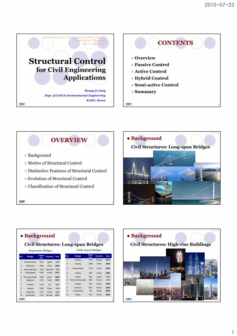
l Background
Civil Structures: Long-span Bridges
Overview
5
No. Bridge Span[m] Country Year
1 Akashi-Kaikyo 1991 Japan 1998
2 Xihoumen 1650 China 2009
3 Great Belt East 1624 Denmark 19984 Gwangyang 1545 Korea 2012
5 Runyang South 1490 China 20056 Nanjing-4 1418 China 2013
7 Humber 1410 UK 1981
8 Jiangyin 1385 China 1999
9 Tsing Ma 1377 China 199710 Hardanger 1310 Norway 2013
No. Bridge Span [m] Country Year
1 Russky 1104 Russia 2012
2 Sutong 1088 China 2008
3 Stonecutters 1018 China 2009
4 Edong 926 China 2009
5 Tatara 890 Japan 19996 Pont de Normandie 856 France 1995
7 Jingsha 816 China 2009
8 Incheon 800 Korea 20099 Chongming 730 China 2009
10 Minpu 708 China 2009
l Background
Civil Structures: Long-span BridgesSuspension Bridges Cable-stayed Bridges
5
Overview
6
6
l Background
Civil Structures: High-rise Buildings
Overview

2010-07-22
2
7
l BackgroundCivil Structures: High-rise Buildings
7
Overview
Increase in construction of high-rise buildings
8
Input OutputSystem
Displacement (Safety)
Acceleration (Serviceability)
Excitation ResponseStructure
Vibration Problem of Structures
l Background
8
Overview
Overview
l Background
Seismically-excited Structures
9
Northridge Earthquake, 1994
72 deaths, 1500 injured, 1000s homeless , > $15B cost10
l BackgroundOverview
Great Hanshin Earthquake, Kobe, Japan, 1995
6434 deaths, 35k injured , 300k homeless , > $150B cost
11
l BackgroundOverview
Sichuan Earthquake, China (2008)
Estimated losses: 70k deaths , 370k injured, 5.0m homeless
l BackgroundOverview
12

2010-07-22
3
Other Recent Earthquakes
13
l Background
Kocaeli (Turkey, 1999)Chi-Chi (Taiwan, 1999)
20,000dead20,000dead>$6B damage>$6B damage
Nisqually (Seattle, WA, 2001)
1 death (heart)1 death (heart)400 injured400 injured$1B$1B--$2B damage$2B damage
India (2001)
20,000 (official) 20,000 (official) ––90,000 (unofficial)90,000 (unofficial)deaddead
2500 dead2500 dead10,000 injured10,000 injured100,000 homeless100,000 homeless
230,000 dead230,000 dead125,000 injured125,000 injured1.69 m homeless1.69 m homeless
Sumatra-Andaman (Indonesia, 2004)
Overview
Tacoma Narrows Bridge, Tacoma, Washington
l Background
Wind-excited Structures
14
Overview
Structure & Aerodynamic instabilityphenomenon
15
l Background
Wind-induced vibration
Period of Phenomenon @ Period of Structure(Resonance)
Overview
l BackgroundWind-excited Structures
Tokyo Wan Aqua-line, Tokyo, Japan16
Overview
Tokyo Wan Aqua-line, Tokyo, Japan
17
l BackgroundWind-excited Structures
Overview
After completion of the superstructure, oscillation with an amplitude over 0.5 m was observed.
To suppress it, 16 tuned mass dampers(TMD) were installed.Part of the steed deck was stiffened. 17
Millennium Foot Bridge, London, England
18
l BackgroundHuman-excited Structures
Overview

2010-07-22
4
l Implementation of passive control systems for retrofitting the bridge§ 37 fluid-viscous dampers (horizontal movement)§ 52 tuned mass dampers (vertical movement)
(www.arup.com/MillenniumBridge/)
l BackgroundHuman-excited Structures
19
Overview
l Increased flexibility¡ the trend toward taller, longer and more flexible structures
l Increased safety levels ¡ higher safety level demands : tall structures, nuclear power
plants
l Increased stringent performance requirements¡ strict performance guide lines: radar tracking stations, radio
telescope structures, aerospace structures
l Better utilization of materials and lower cost¡ economic considerations: savings in materials, weight and
costs
20
Overview
l Motive of Structural Control
l Civil engineering structures are statically stable.¡ the addition of purely active control force can cause
destabilization.¡ in contrast to aerospace structures which requires active
control for stability.
l Loads are highly uncertain.¡ earthquake and wind loads have no definite magnitude and
arrival time.¡ on the other hand, mechanical loads are fairly well
documented.
l Performance requirements are generally coarse.
l Distinctive Features of Structural Control
21
Overview
l Classification of Structural Control
Overview
22
Passive Control
Energy dissipation Friction damper
Metallic yield damper
Viscoelastic damper
Energy transfer
TLD
TMD
Structural Control
Viscous fluid damper
Base isolation TLCD
Semi-active Control
Variable orifice damper
Controllable fluid damperMR damper
ER damper
Hybrid Control
Active ControlActive mass driver
Active tendon
Hybrid mass driver
Active base-isolation
Passive, Active, Semi-active Control
Semi-active Controlcontrollablelittle power required
Active Controlcontrollablesignificant power required
Passive Controlnon-controllableno power required
l Classification of Structural Control
23
Overview
Applicable range of structural control systems
Overview
24
l Classification of Structural Control

2010-07-22
5
Overview
25
Applicable range of structural control systems
l Classification of Structural Control
l The beginning of structural control¡ John Milne (1885): the first example of an isolated building
(a small house of wood on ball bearings)
¡ J. A. Calantarients (1909): a different isolation system to isolate the building from its foundation using layers of talc or mica à building slides during an earthquake.
l Evolution of Structural ControlOverview
26
l Modern structural control concept¡ T. Kobori (1956): proposed a basic concept of active
seismic-response-controlled structure. (the earliest attempt to formulate the problem of active control for applications to civil engineering structures)
¡ J.T.P. Yao (1972): indicated the way to the present active control research in the field of civil engineering.
l Evolution of Structural ControlOverview
27
~1970s 1970s ~ 1990s 1990s ~ 2000s 2010s ~
Passivecontrol
Activecontrol
Semi-activecontrol
Semi-activecontrol???
l Trend of main research topic
l Introduction
l Metallic Yield Dampers
l Friction Dampers
l Viscoelastic Dampers
l Viscous Fluid Dampers
l Tuned Mass Dampers
l Tuned Liquid Dampers
l Base Isolation Systems
PASSIVE CONTROL
28
Energy dissipation(kinetic energy à heat)
Energy transfer
Passive Control Systems
StructureExcitation Response
PED*
M
Passive Damper
M
Base Isolation
M
m
Tuned Mass Damper
* PED: passive energy dissipation 29
l IntroductionPassive Control
l It is usually relatively inexpensive.
l It consumes no external energy (energy may not be
available during a major earthquake).
l It is inherently stable.
l It works even during a major earthquake.
Passive Control
l Introduction
Four Main Advantages of Passive Control
30

2010-07-22
6
l Conversion of kinetic energy to heat:
¡ frictional sliding
¡ yielding of metals
¡ phase transformation in metals
¡ deformation of viscoelastic solids or fluids
¡ fluid orificing
l Transferring of energy among vibrating modes:
¡ supplemental oscillators, which act as dynamic vibration
absorbers.
Passive Control
l Introduction
Energy Dissipation Mechanisms
31
Metallic damper
Viscoelastic damper Fluid damper
Theoretical Behavior of Different Types of Dampers(Force-Displacement Response)
Passive Control
l Introduction
32
Friction damper
Time(sec) Time(sec)
En
ergy
En
ergy
without Damper with Damper
Energy Dissipation Performance
kinetic energy
strain energy from elastic and plasticdeformation
damping energy
kinetic energy
strain energy from elastic deformation
damping energy
33
l IntroductionPassive Control
l Inelastic deformation of metallic substances.
l The idea of utilizing added metallic energy dissipatorswithin a structure to absorb a large portion of the seismic energy: the conceptual and experimental work of Kelly et al. (1972) and Skinner et al. (1975).
l Several of the devices considered: torsional beams, flexural beams, and U-strip energy dissipators.
Passive Control
lMetallic Yield Dampers
34
Passive Control
lMetallic Yield Dampers
Behavior of a damper:Bending under horizontal load
플레이트형ADAS 장치
P
ADAS 장치
보
브레이스
P
P
Installation
Plate-type ADAS
35
The area within the hysteresis loops measures the amount of dissipated energy.
36
lMetallic Yield DampersPassive Control

2010-07-22
7
• A triangular plate damper or triangular added damping and stiffnessdevices (TADAS)
37
lMetallic Yield DampersPassive Control
38
Low-yield strength steel
42-story high-rise RC condominium
Tennozu Project
Copyright 2008 Shimizu Corporation, All Rights Reserved
lMetallic Yield Dampers
38
Honeycomb Damper Installation of Honeycomb Damper
39
lMetallic Yield DampersPassive Control
lFriction Dampers
l Friction:
¡ an excellent mechanism for energy dissipation
¡ used for many years in automotive brakes to dissipate kinetic energy
l It is important to minimize stick-slip phenomena to avoid
introducing high-frequency excitation.
l Compatible materials to maintain a consistent coefficient of
friction over the intended life of device
l Not to slip during wind storms or moderate earthquakes.
à under severe loading conditions, the devices slip at a predetermined
optimum load before yielding occurs in primary structural members.
40
lFriction Dampers
41
Passive Control
l Pall-Friction Damper
41
Disc Springs
Friction Pad Material
Bolt
Steel Plate
Hard Steel Washer
Nut
Steel Plate
Hinge
lFriction Dampersl Rotational Friction Damper
42
Passive Control

2010-07-22
8
Mechanism of the Damper
This new friction damper device is based on rotational friction and designed to:• be stable in performance over many cycles• be compact• be easy to manufacture• be fast and simple to install (no need for a qualified staff)• be requiring little or no maintenance• be inexpensive
TensionRotationRotation
TensionTension
Force
Mechanism of the Damper
Force
43
lFriction Dampersl Rotational Friction Damper
Passive Control Passive Control
lViscoelastic Dampers
44
l Metallic and frictional devices: seismic application
l The VE dampers: applications in both wind and seismic protection
ß VE solid materials can be used to dissipate energy at alldeformation levels
l Characteristics of VE materials1) rate dependent behavior (viscous)2) elastic behavior (elastic) 3) store and dissipate energy at all deformation levels
Steel Plate
Viscoelastic Material
P
P
⇒
Deformed
Steel flangeCenter plate
VE MaterialCenterplate
Steelflange
VE Material
F/2 F/2
F
Typical Hysteretic Loops
Typical Viscoelastic Damper
VE dampers dissipate energy through shear deformation of the VE layers. 45
lViscoelastic DampersPassive Control Passive Control
lViscoelastic Dampers
46
l World Trade Center in New York (1969)
ViscoVisco--elastic elastic damperdamper
• 10,000 Visco-elastic dampers in each tower• Evenly distributed from 10th to the 110th floor• Damping: 2.5%~3%
l The Columbia SeaFirst Building in Seattle (1982)
→ 260 viscoelastic dampers → to reduce wind-induced vibration
VE Damper
47
lViscoelastic DampersPassive Control
l The Two Union Square Building in Seattle (1988)
→ 16 large dampers were installed parallel to four columns
in one floor
→ to reduce wind-induced vibration 48
lViscoelastic DampersPassive Control
2010-07-22
9
Wall TypeWall Type
Brace TypeBrace Type C BuildingC Building
M Department StoreM Department Store
Visco-elastic Material
Copyright 2008 Shimizu Corporation, All Rights Reserved 49
lViscoelastic Dampers
粘
弾
性
体
鋼
板
Q
Q
鋼
板
v(速度)
せん断ひずみ γ=δ/d
d(厚さ) δThickness Thickness (t)(t)
deformation deformation (d)(d)
Shear Strain g = Shear Strain g = d/td/t
Steel Steel PlatePlate
Shear Shear Force (Q)Force (Q)
Steel Steel PlatePlate
ViscoVisco--elastic Materialelastic Material
Shear Shear Force (Q)Force (Q)
50
VE damper 설치 위치
Implementation of VE Damper
core wall
column
wide beam
lViscoelastic Dampers
l Galleria Palace in Seoull Full-scale 5 story steel tower
K.W. Min (Dankook Univ., Korea)
Passive Control
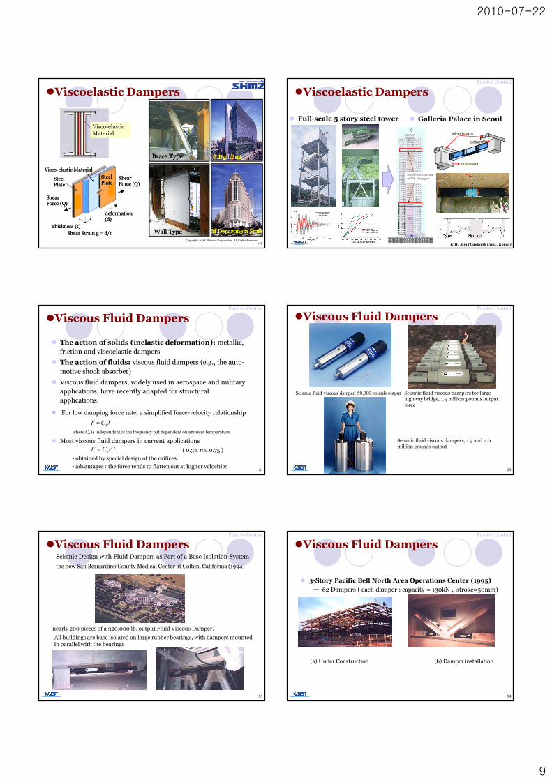
lViscous Fluid Dampers
l The action of solids (inelastic deformation): metallic, friction and viscoelastic dampers
l The action of fluids: viscous fluid dampers (e.g., the auto-motive shock absorber)
l Viscous fluid dampers, widely used in aerospace and military applications, have recently adapted for structural applications.
l Most viscous fluid dampers in current applications
( 0.3 £ n £ 0.75 )
• obtained by special design of the orifices
• advantages : the force tends to flatten out at higher velocities
noVCF =
l For low damping force rate, a simplified force-velocity relationship
XCF &0=
where C0 is independent of the frequency but dependent on ambient temperature
51
Passive Control
Seismic fluid viscous damper, 50,000 pounds output Seismic fluid viscous dampers for large highway bridge, 1.5 million pounds output force
Seismic fluid viscous dampers, 1.3 and 2.0 million pounds output
lViscous Fluid Dampers
52
Passive Control
Seismic Design with Fluid Dampers as Part of a Base Isolation System
the new San Bernardino County Medical Center at Colton, California (1994)
nearly 200 pieces of a 320,000 lb. output Fluid Viscous Damper.
All buildings are base isolated on large rubber bearings, with dampers mounted in parallel with the bearings
lViscous Fluid Dampers
53
Passive Control
l 3-Story Pacific Bell North Area Operations Center (1995)
→ 62 Dampers ( each damper : capacity = 130kN , stroke=50mm)
(a) Under Construction (b) Damper installation
lViscous Fluid Dampers
54
Passive Control
2010-07-22
10
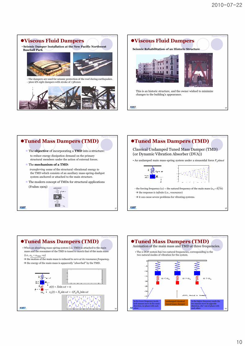
• Seismic Damper Installation at the New Pacific Northwest Baseball Park
- The dampers are used for seismic protection of the roof during earthquakes.- 3600 kN eight dampers with stroke of ±381mm
lViscous Fluid Dampers
55
Passive Control
Seismic Rehabilitation of an Historic Structure
This is an historic structure, and the owner wished to minimize changes to the building's appearance.
lViscous Fluid Dampers
56
Passive Control
l The objective of incorporating a TMD into a structure:
to reduce energy dissipation demand on the primary structural members under the action of external forces.
l The mechanism of a TMD:
transferring some of the structural vibrational energy to the TMD which consists of an auxiliary mass-spring-dashpot system anchored or attached to the main structure.
l The modern concept of TMDs for structural applications
(Frahm 1909)
Passive Control
lTuned Mass Dampers (TMD)
57
Classical Undamped Tuned Mass Damper (TMD) (or Dynamic Vibration Absorber (DVA))
• An undamped main mass-spring system under a sinusoidal force F0sinwt
- the forcing frequency (w) = the natural frequency of the main mass (wn=Ök/m)
à the response is infinite (i.e., resonance)
à it can cause severe problems for vibrating systems.
x
k
m
58
Passive Control
lTuned Mass Dampers (TMD)
• When an absorbing mass-spring system (i.e. TMD) is attached to the main mass and the resonance of the TMD is tuned to match that of the main mass
(i.e., wn = wTMD =w)
à the motion of the main mass is reduced to zero at its resonance frequency.
à the energy of the main mass is apparently "absorbed" by the TMD.
x(t) = Xsin wt = 0
xa(t) = Xasin wt = -(F0/ka)sin wt
ka
ma
k
m
59
Passive Control
lTuned Mass Dampers (TMD)
60
Animation of the main mass and TMD at three frequencies.
• The 2-DOF system has two natural frequencies, corresponding to the two natural modes of vibration for the system.
In the lower frequency mode, both masses move in the same direction, in-phase with each other.
In the higher frequency mode the two masses move in opposite direction, 180° out of phase with each other.
undamped classical tuned mass damper
w < wn w > wnw = wn
60
Passive Control
lTuned Mass Dampers (TMD)

2010-07-22
11
Displacement vs. Frequency plots:
• The plots below show the displacements as a function of normalized frequency (driving frequency divided by natural frequency of main mass).
- The blue dashed curve: the displacement response of the undamped main mass alone. - The blue curve: the displacement of the main mass after undamped TMD has been attached.
(A TMD mass (20% of the main mass) is tuned to the resonance frequency of the main mass.)- The red curve: the displacement of the absorber mass.
- Notes:(1) the main mass has zero displacement at the original problem frequency. (2) there are now two new resonance frequencies.(3) the displacement of the TMD mass is infinite at the same two resonance frequencies.(4) the response at the target frequency is finite (approximately 4.8).
main massdisplacement
TMDdisplacement
61
Passive Control
lTuned Mass Dampers (TMD)l Citicorp Center in New York, USA
62
Passive Control
lTuned Mass Dampers (TMD)
l John Hancock Tower in Boston, USA
63
Passive Control
lTuned Mass Dampers (TMD)• Chiba Port Tower,
Tokyo Bay, Japan
64
Passive Control
lTuned Mass Dampers (TMD)
l Supplementary damping¡ Towers: not necessary
¡ Sky bridge: 3 TMDs per each leg. (73 kg ea)
¡ Pinnacles: simple chain impact dampers
TMD
Petronas Towers: TMD
65
Passive Control
lTuned Mass Dampers (TMD)
66Building TMDBuilding TMD
Pinnacle TMDsPinnacle TMDs
lTuned Mass Dampers (TMD)
66
Taipei 101, Taiwan
2010-07-22
12
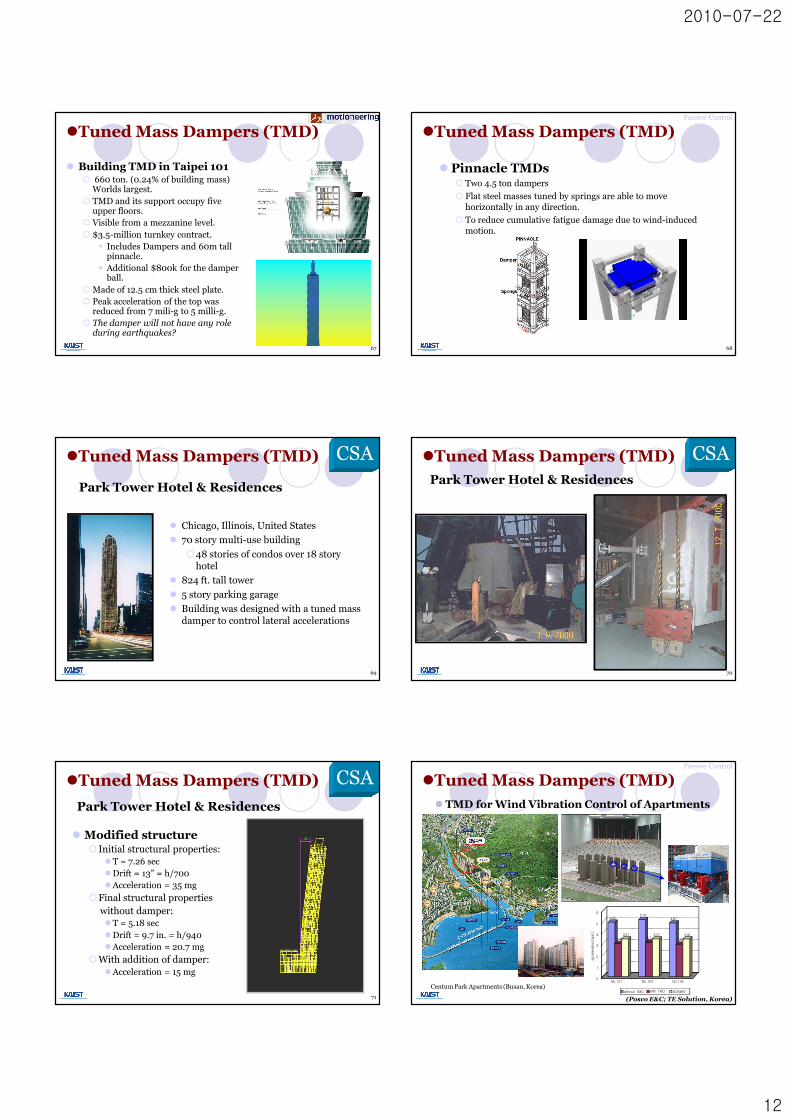
l Building TMD in Taipei 101¡ 660 ton. (0.24% of building mass)
Worlds largest.¡ TMD and its support occupy five
upper floors.¡ Visible from a mezzanine level.¡ $3.5-million turnkey contract.
§ Includes Dampers and 60m tall pinnacle.
§ Additional $800k for the damper ball.
¡ Made of 12.5 cm thick steel plate.¡ Peak acceleration of the top was
reduced from 7 mili-g to 5 milli-g.¡ The damper will not have any role
during earthquakes?
lTuned Mass Dampers (TMD)
67
l Pinnacle TMDs¡ Two 4.5 ton dampers
¡ Flat steel masses tuned by springs are able to move horizontally in any direction.
¡ To reduce cumulative fatigue damage due to wind-induced motion.
68
Passive Control
lTuned Mass Dampers (TMD)
Park Tower Hotel & Residences
l Chicago, Illinois, United States
l 70 story multi-use building
¡48 stories of condos over 18 story hotel
l 824 ft. tall tower
l 5 story parking garage
l Building was designed with a tuned mass damper to control lateral accelerations
CSA
69
lTuned Mass Dampers (TMD)
70
Park Tower Hotel & Residences
CSA
70
lTuned Mass Dampers (TMD)
l Modified structure¡ Initial structural properties:
lT = 7.26 seclDrift = 13” = h/700lAcceleration = 35 mg
¡Final structural properties without damper:lT = 5.18 seclDrift = 9.7 in. = h/940lAcceleration = 20.7 mg
¡With addition of damper:lAcceleration = 15 mg
CSA
71
lTuned Mass Dampers (TMD)
Park Tower Hotel & Residences l TMD for Wind Vibration Control of Apartments
(Posco E&C; TE Solution, Korea)
Centum Park Apartments (Busan, Korea)
4.95
2.98
3.41
5.18
3.12
3.41
4.87
2.94
3.41
0
1
2
3
4
5
6
accele
ration[gal]
No.101 No.103 No.105
without TMD with TMD ISO6897
Passive Control
lTuned Mass Dampers (TMD)

2010-07-22
13
l Liquids are used to provide all of the necessary characteristic of the secondary system.
l The liquid not only supplies the required secondary mass, but also the damping through viscous action primarily in the boundary layers.
l Gravity provides the necessary restoring mechanism.
Passive Control
lTuned Liquid Dampers (TLD)
l In TMD, typically a solid concrete or metal block acts as the secondary mass.
73
TSD
(Tuned Sloshing Damper)
TLCD
(Tuned Liquid Column Damper)
TLD
§ Haneda Airport Air Traffic Control Tower (1993, H=77.6m)
74
Passive Control
lTuned Liquid Dampers (TLD)
Super Sloshing Damper
Tokyo Dome Hotel
75
lTuned Liquid Dampers (TLD)
¡ Two TLCDs at the roof level (290 tons and 430tons)
¡ Large U-shaped tanks at right angles.¡ Moving water mass is 550 tons (0.33% of
building weight) in each tank.¡ Cost effective. Cheaper than a pendulum
TMD.
lTuned Liquid Dampers (TLD)
l Tuned Liquid Column Damper in Random House
76
77
0 20 40 60 80-0.5
0
0.5
Time (sec)
Acc
. (m
/sec
2 )
UncontrolledControlled
0 1 2 30
0.1
0.2
0.3
0.4
0.5
Frequency (Hz)
Pea
k A
cc. (
m/s
ec2 )
UncontrolledControlled
(POSCO E&C and RIST, Korea)
Test ResultsSmall-scale Experimental Test
Passive Control
lTuned Liquid Dampers (TLD)
l TLCD for Wind Vibration Control of Apartments l One of the most widely implemented and accepted control strategies
l Decouple the structures and/or its components from potentially damaging earthquake-induced ground or support motions .
l Allow large deformations of control devices to achieve these goals.
Acceleration response spectrum Displacement response spectrum
Period shift
Period
Acc
eler
atio
n
Dampingeffect
Period shift
Period
Dis
plac
emen
t
Dampingeffect
Passive Control
lBase Isolation System
78

2010-07-22
14
• During an earthquake, a fixed-base building can sway from side to side.
• When a base isolation system is used, the sideways movement occurs mainly in the bearings, and the building hardly distorts at all.
79
Base Isolation SystemPassive Control
l Basic requirements of base isolation
l Seismic behavior of base isolated structures
1. Flexibility
2. Energy dissipation capacity
3. Sufficient stiffness under small load
Passive Control
lBase Isolation System
80
Conventional bridges with earthquake resistant designHorizontal force is concentrated on a rigid pier.
81
Passive Control
lBase Isolation System
Load dispersing bridge (Base Isolated)RB and LRB are used to disperse the horizontal force induced on each pier.
82
Passive Control
lBase Isolation System
Seismic isolation bridgeLRB is used to increase the vibration period and damp the vibration.
83
Passive Control
lBase Isolation System
Square Base Isolators made of Multilayer Natural Rubber with an internal Lead Plug
84
Passive Control
lBase Isolation System

2010-07-22
15
Function
Multi-layer rubber isolator Function
(1) Load supporting / Rotation Absorbing function
- Rubber reinforced with steel plates provides stable support for structures- Multilayer construction provides better vertical rigidity than single layer rubber pads for supporting a building.
85
Passive Control
lBase Isolation System
(2) Horizontal elasticity function (prolonged oscillation period)- Earthquake vibration is converted to low speed motion- As horizontal stiffness of the multi-layer rubber bearing is low, strong earthquake vibration is alleviated and the oscillation period of the building is increased.
(3) Restoration function- Horizontal elasticity returns the building to its original position.- After an earthquake the restoring force of the rubber layers returns the
building to the original position.86
Passive Control
lBase Isolation System
Function of lead plug (damper)
(4) Vibration damping function- It absorbs large vibration of the structure- As the layers of rubber are distorted, the lead plug is plastically deformed, which
absorbs the earthquake energy and quickly damps the vibration.
(5) Trigger function- Reduces vibration from sources other than earthquake.- Vibration generated by strong winds are avoided as the relative rigidity of the lead
plug restricts the flexibility of the isolation system until the plug is subjected to a certain level of force. 87
Passive Control
lBase Isolation SystemPassive Control
88
USC Hospital(First base-isolated hospital in U.S.)
New LA Cathedral(under construction)
LA City Hall(in retrofit)
rubber bearings
friction pendulum bearings
bearings in basement
lBase Isolation System
Base-isolated Condominiums
89
Passive Control
lBase Isolation SystemLead Rubber Bearings (LRB) in Bridges Base Isolators in Bridges
90
Passive Control
lBase Isolation System

2010-07-22
16
Example: LNG Tank
91
Passive Control
lBase Isolation SystemExample: Tohoku Univ.
Acceleration resp. of left bld.
Acceleration resp. of right bld.
92
Passive Control
lBase Isolation System
l Introduction
l Actuators
l Control Algorithms
l Full-scale Applications
ACTIVE CONTROL
Active Control
93
StructureExcitation Response
Computer
Control Actuators
Sensors
FeedbackLink
Sensors
FeedforwardLink
Active Control Systems
94
l IntroductionActive Control
Active Bracing
M
Actuator
Sensor
Active Mass Damper
M
Actuator Sensors
m
Control Computer
Active Control Systems
95
l IntroductionActive Control
l Initial concept paper: J.T.P. Yao (1972)
l An external source powers control actuator(s) that apply forces to the structure in a prescribed manner.
l Control forces can be used to both add and dissipate energy in the structure.
l In an active feedback system, the signals sent to the control actuators are a function of the response of the system measured with physical sensors (optical, mechanical, electrical, chemical, and so on).
Active Control Systems
96
l IntroductionActive Control

2010-07-22
17
l Advantages (attractive features):¡ enhanced effectiveness in motion control
¡ relative insensitivity to site conditions and ground motions
¡ applicability to multi-hazard situations
¡ greater ability to select control objectives
l Disadvantages (issues to be solved):¡ Capital cost and maintenance
¡ reliance on external power
¡ system reliability and stability
¡ gaining acceptance by the profession
l IntroductionActive Control
97
Active Control
98
l Introduction
l Active structural control is not popular for seismic hazard mitigation because¡ Energy consumption during seismic events, when power blackout
is highly likely to occur
¡ Stability concern: what if the control system becomes unstable?
l Active structural control is still very useful for reducing wind-induced vibrations in bridges and buildings¡ Active mass damper (AMD)
¡ Hybrid mass damper (HMD)
Active Mass Driver (AMD) Experiment:Acceleration Feedback Control Strategies
Control Computer/DSP Board
)(act tz
)(a1 tz&&
)(g tz&&
)(a3 tz&&
)(a2 tz&&
Active Control
l Introduction
99(B.F. Spencer, Jr., UIUC)
2 translational1 translational &
rotational2 translational &
rotational
Arrangement of AMD
l IntroductionActive Control
100
lControl AlgorithmsActive Control
101
l Optimal Control
l Stochastic Control
l Adaptive Control
l Intelligent Control§ Neural network-based control (i.e., neuro-controller)
§ Fuzzy logic-based control (i.e., fuzzy controller)
l Sliding Mode Control
l Robust Control
Kyobashi Seiwa Building (1989)
AMD-1
AMD-2Control Computer
Sensor
Sensor
Sensor
lFull-scale ApplicationsActive Control
102

2010-07-22
18
Kyobashi Seiwa Building (1989)
lFull-scale ApplicationsActive Control
103
Yokohama Landmark Tower (1993): AMD
lFull-scale ApplicationsActive Control
104
Shinjuku Park Tower (1994): AMD
lFull-scale Applications
105
Active Control
0 500 1000 1500 2000 2500 3000-10
-5
0
5
10Bending 23F X-dir
x uncont
x cont
0 500 1000 1500 2000 2500 3000-5
0
5Bending 23F Y-dir
y uncont
y cont
0 500 1000 1500 2000 2500 3000-4
-3
-2
-1
0
1
2
3Rotation 23F
theta uncont
theta cont
AMD for Wind Vibration Control of Building in Use(2007)
0 10 20 30 40 50 60 70 80 90 100-10
0
10
Accele
ration
G
al
Unit No. 1 side
0 10 20 30 40 50 60 70 80 90 100-10
0
10
Accele
ration
G
al
Unit No. 2 side
0 10 20 30 40 50 60 70 80 90 100-20
0
20
Dis
pla
cem
ent
cm
Unit No. 1
0 10 20 30 40 50 60 70 80 90 100-20
0
20
Time s
Dis
pla
cem
ent
cm
Unit No. 2
0 10 20 30 40 50 60 70 80 90 100-10
0
10
Acc
eler
atio
n
Gal
Unit No. 1 side
0 10 20 30 40 50 60 70 80 90 100-10
0
10
Acc
eler
atio
n
Gal
Unit No. 2 side
0 10 20 30 40 50 60 70 80 90 100-40
-20
0
20
40
Dis
plac
emen
t
cm
Unit No. 1
0 10 20 30 40 50 60 70 80 90 100-40
-20
0
20
40
Time s
Dis
plac
emen
t
cm
Unit No. 2
Numerical VerificationFree Vibration TestUncontrolled case Controlled case
AMD System
Active Control
106
lFull-scale Applications
(Lotte E&C and KAIST)
lFull-scale Applications
(Lotte E&C and KAIST)
Reinforcement Lifting Temporary Hoist Frame
Assembling Control Panel Completion
Active Control
AMD for Wind Vibration Control of Building in Use(2007)
HYBRID CONTROL
l Introduction
l Hybrid Mass Damper (HMD)
l (Semi-)Active Base Isolation
l Full-scale Applications
108

2010-07-22
19
StructureExcitation Response
Computer
Control Actuators
Sensors
FeedbackLink
Sensors
FeedforwardLink
Hybrid Control Systems(passive devices + (semi-)active system)
109
PED
lIntroductionHybrid Control
l The combined use of active and passive control systems
l For example, ¡ a structure equipped with distributed viscoelastic damping
supplemented with an active mass damper on or near the top of the structure
¡ A base isolated structure with actuators actively controlled to enhance performance
¡ The hybrid mass damper (HMD) is a combination of a TMD and an active control actuator, which is the most common control device employed in full-scale civil engineering applications.
Hybrid Control Systems
110
lIntroductionHybrid Control
(Semi-)Active BaseIsolation
M
Actuator or MR damper Sensor
Control Computer
Hybrid Control Systems
111
lIntroductionHybrid Control
Hybrid Mass Damper
MActuator
Sensorsm
l The most common control device in full-scale structure
l HMD = TMD + active control actuator
l Advantages- compact
- efficient
- practically implementable
lHybrid Mass Damper (HMD)
• DUOX HMD
- high control efficiency with a small actuator force
Hybrid Control
112
20 40 60 80 100 120 140-0.10
-0.05
0.00
0.05
0.10
Accel
eratio
n (m/
s2 )
Time (sec)
TMDmode Uncontrolled
x
y
HMD1
HMD2
Air Traffic Control Tower: 100. 4 mNatural Freqeuncy: 0.71 Hz
Location of HMDs: 19th Floor (80 m above ground)
20 40 60 80 100 120 140-0.10
-0.05
0.00
0.05
0.10
Accel
eratio
n (m/
s)
Time (sec)
Controlled byHMD mode
Hybrid Mass Damper (HMD)
HMD for Air-traffic Control Tower (Incheon Int’l Airport)
Signal w/o HMD Signal w/ HMD
Hybrid Control
113
lFull-scale Applications
114
l Active tuned mass damper¡ Two dampers on the 90th floor.
¡ Sensors are used to measure the building sway with a computer to control
• Shape– The Hole in the building reduces vortex-
shedding induced force.
Shanghai World Financial Center: HMD
lFull-scale ApplicationsHybrid Control

2010-07-22
20
Hybrid (or Smart) Base Isolation
MR Damper
gx&&
115(B.F. Spencer, Jr. (UIUC))
Experimental Setup
[parameters of the experimental model]• mass of the base: 10.5 kg• mass of the structure: 57.5 kg• total mass: 68 kg
• Max force of the MR damper (at current of 0.5 A): 45 N6.6 % of the total mass
116(B.F. Spencer, Jr. (UIUC))
Experimental Setup
%5.3Hz),(3.88Hz65.11%0.1,Hz)(0.47 Hz42.1
22
11
====z
zff
117(B.F. Spencer, Jr. (UIUC))
Structural Acceleration
-0.15-0.1
-0.050
0.050.1
0.15
0 2 4 6 8 10
Acc
eler
atio
n [g
]
-0.4-0.2
00.20.4
0 2 4 6 8 10
Acc
. [g] Max: 0.2g(0.44g for full scale)
Response to Strong Earthquake
Without damper
Optimal passive(constant voltage)
Smart damping
28 % reduction (Peak)29 % reduction (RMS)
46 % reduction (Peak)59 % reduction (RMS)
Input Motion (El Centro NS)
118(B.F. Spencer, Jr. (UIUC))
-0.04-0.02
00.02
0.04
0 2 4 6 8 10
Acc
eler
atio
n [g
]
Structural Acceleration
Without damper
Optimal passive(constant voltage)
Smart Damper
49 % increase (Peak)49 % increase (RMS)
37 % reduction (Peak)49 % reduction (RMS)
Input Motion (El Centro NS)
Max: 0.07g(0.15g for full scale)
Response to Moderate Earthquake
-0.4-0.2
00.20.4
0 2 4 6 8 10
Acc
. [g]
119(B.F. Spencer, Jr. (UIUC))
SEMI-ACTIVE CONTROL
l Introduction
l MR Fluids and Dampers
l MR Damper-based Control Systems
l Control of Cable Vibration
l Limitation of Semi-active Control
120

2010-07-22
21
Semi-active Control Systems
StructureExcitation Response
Sensors SensorsComputer
Control Actuators
PED
121
lIntroductionSemi-active Control
Semi-active Control Devices® combine the best features of both passive and active control
® don’t require large power sources : can operate on battery power, which is critical during seismic events when the main power source to structure may fail
® performance is better than passive devices and have potential to achieve similar performance with fully active devices
Definition
¡ cannot inject mechanical energy into the controlled structure, but has properties that can be controlled to optimally reduce the responses of the system
®have no potential to destabilize the structural system
(Bounded Input-Bounded Output stability)
Semi-active Control
lIntroduction
122
Control Computer
Semi-active Control Systems
123
Smart Base Isolation
MMR elastomer
Sensor
Semi-active TMD
M
MR damper Sensors
m
lIntroductionSemi-active Control
Semi-active damper
M
MR damper
Sensor
Control Computer
Smart Damping?
lIntroductionSemi-active Control
124
Smart Damping?
lIntroductionSemi-active Control
125
Smart Damping?
lIntroductionSemi-active Control
126

2010-07-22
22
127
Kajima Shizuoka Building:Observations from the May 7, 1999 M4.9 Earthquake
Full-scale Applications
lIntroductionSemi-active Control
lK-Building
Hybrid mass damper: 2
Semi-activehydraulic damper: 88
238.05m, 54 story
Semi-activehydraulic dampers: 356
lR-Building
Full-scale Applications
lIntroductionSemi-active Control
128
• Micron-sized, polarizable, iron particles in oil
l What do they do?
• Newtonian in the absence of applied field
• Develop yield strength when field applied
• Provide reliable means for a low-power, rapid response interface between electronic controls and mechanical devices
l What are they?
Semi-active Control
129
MR Fluids
l MR Fluids and Dampers
l Magnetorheological (MR) dampers are semi-active control devices that use MR fluids to produce controllable dampers.
l Attractive features:– High dissipative force at low velocity.
– Continual optimization.
– High dynamic range
– Inherent stability and failure-safety.
– Mechanical simplicity.
– Fast response-time.
– Small device size.
– Large temperature range.
Semi-active Control
130
Annular Orifice
l MR Fluids and DampersMR Dampers
MR Fluid Linear Damper:- used in semi-active suspension system
- used in highway vehicle seats
Semi-active Control
131
l MR Fluids and Dampers
Responses due to 120% El Centro Earthquake
Measured Response• 75% reduction in peak displacements• 50% reduction in peak accelerations• 30% better response reduction than when
device is operated in passive capacity
CurrentDriver
ControlComputer
Rheonetic SD-1000MR Damper
3-Story Scale-Model Building
Height: 158 cmMass: 304 kg
gx&&
dxf ,
1ax&&
2ax&&
3ax&&
lMR Damper-based Control SystemSemi-active Control
132(B.F. Spencer, Jr., UIUC)

2010-07-22
23
Nihon-Kagaku-Miraikan, Tokyo
National Museum of Emerging Science and Innovation Two 30-ton, MR Fluid dampers b
uilt by Sanwa Tekki using Lord MR fluid are installed between 3rd and 5th floors
Full-scale Applications: Building
133
Semi-active Control
lMR Damper-based Control System
134
Semi-active Control
lMR Damper-based Control SystemFull-scale Applications: Base-isolated Building
Existing solutions:• Cable restrainers which tie
together cables
• Altered surface roughness on cables
Control of Stay Cable Vibration using MR Dampers
Dampers
Bridge Deck
Standard Solution
• Augment damping through discrete viscous dampers attached transverse to cable
New Solution
lControl of Cable VibrationSemi-active Control
0 1000 2000 3000-20
-10
0
10
20
(a) A10 In-Plane Time (s)
Acc
eler
atio
n (m
/s2 )
0 1000 2000 3000-20
-10
0
10
20
(b) A10 Out-of-Plane Time (s)
Acc
eler
atio
n (m
/s2 )
0 1000 2000 3000-20
-10
0
10
20
(c) A11 In-Plane Time (s)
Acc
eler
atio
n (m
/s2 )
0 1000 2000 3000-20
-10
0
10
20
(d) A11 Out-of-Plane Time (s)
Acc
eler
atio
n (m
/s2 )
0 1000 2000 3000-20
-10
0
10
20
(e) A12 In-Plane
Acc
eler
atio
n (m
/s2 )
0 1000 2000 3000-20
-10
0
10
20
(f) A12 Out-of-Plane Time (s)
Acc
eler
atio
n (m
/s2 )
Time (s)
Acceleration time-history response (0s ~ 2600s)
A10
(without damper)
A11
(With Twin-damper)
In-plane Out-of-plane
A12
(without damper)
II
In-plane accelerometer
Out-of-plane accelerometer
MR damperDisplacement transducer
Damper Installation and Test Results
(Y.Q. Ni, 2001)
Semi-active Control
lControl of Cable Vibration
Field Test Results
(Y.Q. Ni, 2001)
0.000.100.200.300.400.500.600.70
0 4 8 12
Voltage (v)
Dam
ping
Rat
io (%
)
Single Damper Without Damper
Damping ratios of 1st in-plane mode under vibration amplitude 0.04~0.07 m/s2
Semi-active Control
lControl of Cable VibrationFull Installation and Verification
(Y.Q. Ni, 2001)
Semi-active Control
lControl of Cable Vibration
2010-07-22
24
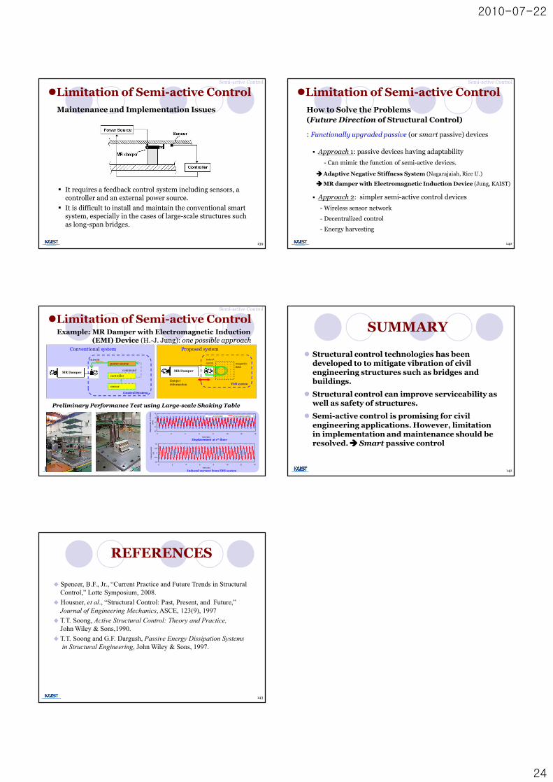
§ It requires a feedback control system including sensors, a controller and an external power source.
§ It is difficult to install and maintain the conventional smart system, especially in the cases of large-scale structures such as long-span bridges.
Maintenance and Implementation Issues
lLimitation of Semi-active Control
139
Semi-active Control
: Functionally upgraded passive (or smart passive) devices
§ Approach 1: passive devices having adaptability
- Can mimic the function of semi-active devices.
§ Approach 2: simpler semi-active control devices
- Wireless sensor network
- Decentralized control
- Energy harvesting
lLimitation of Semi-active Control
How to Solve the Problems(Future Direction of Structural Control)
Semi-active Control
140
à Adaptive Negative Stiffness System (Nagarajaiah, Rice U.)
à MR damper with Electromagnetic Induction Device (Jung, KAIST)
lLimitation of Semi-active ControlExample: MR Damper with Electromagnetic Induction
(EMI) Device (H.-J. Jung): one possible approach
MR Damper
´ ´ ´´´ ´ ´´´ ´ ´´´ ´ ´´´ ´ ´´´ ´ ´´´ ´ ´´´ ´ ´´
´ ´´´ ´´´ ´´´ ´´´ ´´´ ´´´ ´´´ ´´
damper deformation
magnetic field
Induced
current
EMI system
Proposed system
Preliminary Performance Test using Large-scale Shaking Table
MR Dampercontroller
power source
command
current
Control System
sensor
Conventional system
-8
-4
0
4
8
0 2 4 6 8 10 12 14
time (sec)
disp
lace
men
t at 1
st fl
oor
(mm
)
uncontrolled smart passive system
-1.6
-0.8
0
0.8
1.6
0 2 4 6 8 10 12 14
time (sec)
indu
ced
curre
nt(A
)
Induced current from EMI system
Displacement at 1st floor
Semi-active Control
l Structural control technologies has been developed to to mitigate vibration of civil engineering structures such as bridges and buildings.
l Structural control can improve serviceability as well as safety of structures.
l Semi-active control is promising for civil engineering applications. However, limitation in implementation and maintenance should be resolved. à Smart passive control
SUMMARY
142
u Spencer, B.F., Jr., “Current Practice and Future Trends in StructuralControl,” Lotte Symposium, 2008.
u Housner, et al., “Structural Control: Past, Present, and Future,”Journal of Engineering Mechanics, ASCE, 123(9), 1997
u T.T. Soong, Active Structural Control: Theory and Practice,John Wiley & Sons,1990.
u T.T. Soong and G.F. Dargush, Passive Energy Dissipation Systems in Structural Engineering, John Wiley & Sons, 1997.
REFERENCES
143