problem 4 - faculty server contact | umass...
TRANSCRIPT

PROPRIETARY MATERIAL. © 2012 The McGraw-Hill Companies, Inc. All rights reserved. No part of this Manual may be displayed, reproduced, or distributed in any form or by any means, without the prior written permission of the publisher, or used beyond the limited distribution to teachers and educators permitted by McGraw-Hill for their individual course preparation. A student using this manual is using it without permission.
PROBLEM 4.1
Knowing that the couple shown acts in a vertical plane, determine the stress at (a) point A, (b) point B.
SOLUTION
For rectangle: 3112
I bh=
For cross sectional area:
3 3 3 41 2 3
1 1 1(2)(1.5) (2)(5.5) (2)(1.5) 28.854 in12 12 12
I I I I= + + = + + =
(a) 2.75 in.Ay = (25)(2.75)28.854
AA
MyI
! = " = " 2.38 ksiA! = " W�
(b) 0.75 in.By = (25)(0.75)28.854
BB
MyI
! = " = " 0.650 ksiB! = " W
PROPRIETARY MATERIAL. © 2012 The McGraw-Hill Companies, Inc. All rights reserved. No part of this Manual may be displayed, reproduced, or distributed in any form or by any means, without the prior written permission of the publisher, or used beyond the limited distribution to teachers and educators permitted by McGraw-Hill for their individual course preparation. A student using this manual is using it without permission.
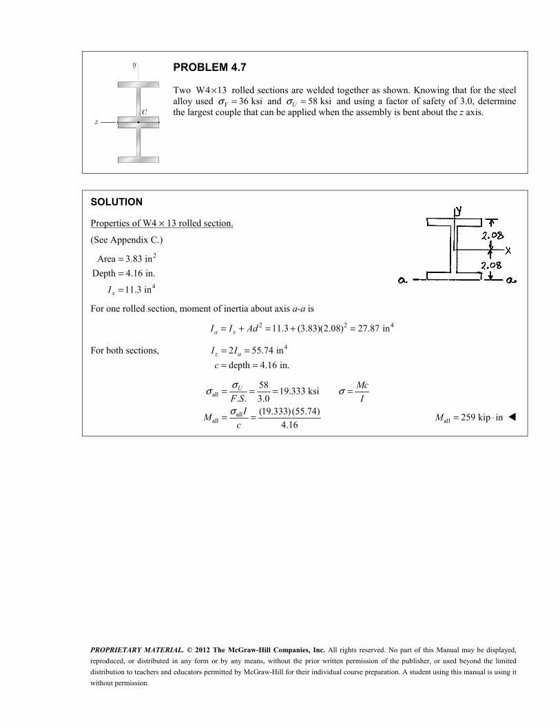
PROBLEM 4.7
Two W4 13# rolled sections are welded together as shown. Knowing that for the steel alloy used 36 ksiY! = and 58 ksiU! = and using a factor of safety of 3.0, determine the largest couple that can be applied when the assembly is bent about the z axis.
SOLUTION
Properties of W4 # 13 rolled section.
(See Appendix C.) 2
4
Area 3.83 inDepth 4.16 in.
11.3 inxI
===
For one rolled section, moment of inertia about axis a-a is
2 2 411.3 (3.83)(2.08) 27.87 ina xI I Ad= + = + =
For both sections, 42 55.74 indepth 4.16 in.
z aI Ic
= == =
all
allall
58 19.333 ksi. . 3.0
(19.333) (55.74)4.16
!! !
!
= = = =
= =
U McF S IIMc
all 259 kip inM = $ W

PROPRIETARY MATERIAL. © 2012 The McGraw-Hill Companies, Inc. All rights reserved. No part of this Manual may be displayed, reproduced, or distributed in any form or by any means, without the prior written permission of the publisher, or used beyond the limited distribution to teachers and educators permitted by McGraw-Hill for their individual course preparation. A student using this manual is using it without permission.
PROBLEM 4.9
Two vertical forces are applied to a beam of the cross section shown. Determine the maximum tensile and compressive stresses in portion BC of the beam.
SOLUTION
2 2 21 1
22 2
4 (4)(25)(25) 981.7 mm 10.610 mm2 2 3 3
25(50)(25) 1250 mm 12.5 mm2 2
rA r y
hA bh y
% %% %
= = = = = =
= = = = " = " = "
1 1 2 2
1 2
(981.7)(10.610) (1250)( 12.5) 2.334 mm981.7 1250
A y A yyA A
+ + "= = = "+ +
1
2 4 2 4 2 6 41 1 1 1 1
1 12 3 2 3 4
1 1 1 1
3 3 3 42
2 2
(25) (981.7)(10.610) 42.886 10 mm8 8
10.610 ( 2.334) 12.944 mm
42.866 10 (981.7)(12.944) 207.35 10 mm1 1 (50)(25) 65.104 10 mm
12 1212.5
xI I A y r A y
d y y
I I A d
I bh
d y y
% %= " = " = " = #
= " = " " =
= + = # + = #
= = = #
= " = "2 3 2 3 4
2 2 2 23 4 9 4
1 2
top
bot
( 2.334) 10.166 mm
65.104 10 (1250)(10.166) 194.288 10 mm
401.16 10 mm 401.16 10 m25 2.334 27.334 mm 0.027334 m
25 2.334 22.666 mm 0.022666 m
I I A d
I I Iy
y
"
" " =
= + = # + = #
= + = # = #= + = == " + = " = "
3 30 : (4 10 )(300 10 ) 1200 N mM Pa M Pa "" = = = # # = $
top 6top 9
(1200)(0.027334) 81.76 10 Pa401.16 10
MyI
! ""
= = " = " ##
top 81.8 MPa! = " W
6botbot 9
(1200)( 0.022666) 67.80 10 Pa401.16 10
MyI
! "" "= = " = #
# bot 67.8 MPa! = W

PROPRIETARY MATERIAL. © 2012 The McGraw-Hill Companies, Inc. All rights reserved. No part of this Manual may be displayed, reproduced, or distributed in any form or by any means, without the prior written permission of the publisher, or used beyond the limited distribution to teachers and educators permitted by McGraw-Hill for their individual course preparation. A student using this manual is using it without permission.
PROBLEM 4.14
Knowing that a beam of the cross section shown is bent about a horizontal axis and that the bending moment is 50 kip $ in., determine the total force acting (a) on the top flange, (b) on the shaded portion of the web.
SOLUTION
The stress distribution over the entire cross-section is given by the bending stress formula: xMyI
! = "
where y is a coordinate with its origin on the neutral axis and I is the moment of inertia of the entire cross sectional area. The force on the shaded portion is calculated from this stress distribution. Over an area element dA, the force is
xMydF dA dAI
!= = "
The total force on the shaded area is then
* *My M MF dF dA ydA y AI I I
= = " = " = "³ ³ ³
where *y is the centroidal coordinate of the shaded portion and A* is its area.
Calculate the moment of inertia.
3 3 41 1(6 in.)(7 in.) (4 in.)(4 in.) 150.17 in12 1250 kip in
I
M
= " =
= $
(a) Top flange: 2* (6 in.)(1.5 in.) 9 in * 2 in. 0.75 in. 2.75 in.A y= = = + =
24
50 kip in (9 in )(2.75 in.) 8.24 kips150.17 in
F $= = 8.24 kipsF = W�
(b) Half web: 2* (2 in.)(2 in.) 4 in * 1 in.A y= = =
24
50 kip in (4 in )(1 in.) 1.332 kips150.17 in
F $= = 1.332 kipsF = W

PROPRIETARY MATERIAL. © 2012 The McGraw-Hill Companies, Inc. All rights reserved. No part of this Manual may be displayed, reproduced, or distributed in any form or by any means, without the prior written permission of the publisher, or used beyond the limited distribution to teachers and educators permitted by McGraw-Hill for their individual course preparation. A student using this manual is using it without permission.
PROBLEM 4.24
A 60 N $ m couple is applied to the steel bar shown. (a) Assuming that the couple is applied about the z axis as shown, determine the maximum stress and the radius of curvature of the bar. (b) Solve part a, assuming that the couple is applied about the y axis. Use 200 GPa.E =
SOLUTION
(a) Bending about z-axis.
3 3 3 4 9 41 1 (12)(20) 8 10 mm 8 10 m12 1220 10 mm 0.010 m2
"= = = # = #
= = =
I bh
c
69
(60)(0.010) 75.0 10 Pa8 10
McI
! "= = = ##
75.0 MPa! = W
3 19 9
1 60 37.5 10 m(200 10 )(8 10 )
MEI&
" ""= = = #
# # 26.7 m& = W
(b) Bending about y-axis.
3 3 3 4 9 4
69
1 1 (20)(12) 2.88 10 mm 2.88 10 m12 1212 6 mm 0.006 m2
(60)(0.006) 125.0 10 Pa2.88 10
I bh
c
McI
!
"
"
= = = # = #
= = =
= = = ##
125.0 MPa! = W
3 19 9
1 60 104.17 10 m(200 10 )(2.88 10 )
MEI&
" ""= = = #
# # 9.60 m& = W�

PROPRIETARY MATERIAL. © 2012 The McGraw-Hill Companies, Inc. All rights reserved. No part of this Manual may be displayed, reproduced, or distributed in any form or by any means, without the prior written permission of the publisher, or used beyond the limited distribution to teachers and educators permitted by McGraw-Hill for their individual course preparation. A student using this manual is using it without permission.
PROBLEM 4.34
A bar having the cross section shown has been formed by securely bonding brass and aluminum stock. Using the data given below, determine the largest permissible bending moment when the composite bar is bent about a horizontal axis.
Aluminum Brass
Modulus of elasticity 70 GPa 105 GPa
Allowable stress 100 MPa 160 MPa
SOLUTION
Use aluminum as the reference material.
For aluminum, 1.0n =
For brass, / 105/70 1.5b an E E= = =
Values of n are shown on the sketch.
For the transformed section,
( )
3 3 3 411 1 1
3 3 3 3 3 422 2 2 2
3 43 1
3 4 9 41 2 3
1.5 (8)(32) 32.768 10 mm12 12
1.0 (32)(32 16 ) 76.459 10 mm12 12
32.768 10 mm
141.995 10 mm 141.995 10 m
nI b h
nI b H h
I I
I I I I "
= = = #
= " = " = #
= = #
= + + = # = #
| | !! = =nMy IMI ny
Aluminum: 6
6 9
1.0, | | 16 mm 0.016 m, 100 10 Pa
(100 10 )(141.995 10 ) 887.47 N m(1.0)(0.016)
!"
= = = = ## #= = $
n y
M
Brass: 6
6 9
1.5, | | 16 mm 0.016 m, 160 10 Pa
(160 10 )(141.995 10 ) 946.63 N m(1.5)(0.016)
!"
= = = = ## #= = $
n y
M
Choose the smaller value. 887 N mM = $ W�

PROPRIETARY MATERIAL. © 2012 The McGraw-Hill Companies, Inc. All rights reserved. No part of this Manual may be displayed, reproduced, or distributed in any form or by any means, without the prior written permission of the publisher, or used beyond the limited distribution to teachers and educators permitted by McGraw-Hill for their individual course preparation. A student using this manual is using it without permission.
PROBLEM 4.41
The 6 12-in.# timber beam has been strengthened by bolting to it the steel reinforcement shown. The modulus of elasticity for wood is 61.8 10 psi# and for steel, 629 10 psi.# Knowing that the beam is bent about a horizontal axis by a couple of moment 450 kip in.,M = $ determine the maximum stress in (a) the wood, (b) the steel.
SOLUTION
Use wood as the reference material.
For wood, 1For steel, / 29 /1.8 16.1111s w
nn E E
== = =
Transformed section: c = wood d = steel
421.931112.2783.758 in.
oY =
=
The neutral axis lies 3.758 in. above the wood-steel interface.
3 2 3 2 411 1 1 1 1 1
3 2 3 2 422 2 2 2 2 2
41 2
1 (6)(12) (72)(6 3.758) 1225.91 in12 12
16.1111(5) (0.5) (40.278)(3.578 0.25) 647.87 in12 12
1873.77 in
450 kip in
nI b h n A d
nI b h n A d
I I InMyMI
!
= + = + " =
= + = + + =
= + =
= $ = "
(a) Wood: 1, 12 3.758 8.242 inn y= = " =
(1) (450) (8.242) 1.979 ksi1873.77w! = " = " 1.979 ksiw! = " W
(b) Steel: 16.1111, 3.758 0.5 4.258 inn y= = " " = "
(16.1111) (450) ( 4.258) 16.48 ksi1873.77s! "= " = 16.48 ksis! = W
2, inA 2, innA oy 3, inonAy
c 72 72 6 432
d 2.5 40.278 "0.25 "10.069
112.278 421.931

PROPRIETARY MATERIAL. © 2012 The McGraw-Hill Companies, Inc. All rights reserved. No part of this Manual may be displayed, reproduced, or distributed in any form or by any means, without the prior written permission of the publisher, or used beyond the limited distribution to teachers and educators permitted by McGraw-Hill for their individual course preparation. A student using this manual is using it without permission.
PROBLEM 4.42
The 6 12-in.# timber beam has been strengthened by bolting to it the steel reinforcement shown. The modulus of elasticity for wood is 61.8 10 psi# and for steel, 629 10 psi.# Knowing that the beam is bent about a horizontal axis by a couple of moment 450 kip in.,M = $ determine the maximum stress in (a) the wood, (b) the steel.
SOLUTION Use wood as the reference material.
6
6
For wood, 1
29 10For steel, 16.11111.8 10
s
w
n
EnE
=#= = =#
For C8 11.5# channel section,
2 43.38 in , 0.220 in., 0.571 in., 1.32 inw yA t x I= = = =
For the composite section, the centroid of the channel (part 1) lies 0.571 in. above the bottom of the section. The centroid of the wood (part 2) lies 0.220 6.00 6.22 in.+ = above the bottom.
Transformed section:
3
0 2478.93 in 3.787 in.
126.456 inY = = 0 0d y Y= "
The neutral axis lies 3.787 in. above the bottom of the section.
2 2 41 1 1 1 1 1
3 2 3 2 422 2 2 2 2 2
41 2
(16.1111)(1.32) (54.456)(3.216) 584.49 in1 (6)(12) (72)(2.433) 1290.20 in
12 121874.69 in
450 kip in
I n I n A dnI b h n A d
I I InMyMI
!
= + = + =
= + = + =
= + =
= $ = "
(a) Wood: 1, 12 0.220 3.787 8.433 in.n y= = + " =
(1)(450)(8.433) 2.02 ksi1874.69w! = " = " 2.02 ksiw! = " W
(b) Steel: 16.1111, 3.787 in.n y= = "
(16.1111) (450) ( 3.787) 14.65 ksi1874.67s! "= " = 14.65 ksis! = W
Part A, in2 nA, in2 , in.y 3, innAy d, in.
1 3.38 54.456 0.571 31.091 3.216
2 72 72 6.22 447.84 2.433
' 126.456 478.93

PROPRIETARY MATERIAL. © 2012 The McGraw-Hill Companies, Inc. All rights reserved. No part of this Manual may be displayed, reproduced, or distributed in any form or by any means, without the prior written permission of the publisher, or used beyond the limited distribution to teachers and educators permitted by McGraw-Hill for their individual course preparation. A student using this manual is using it without permission.
PROBLEM 4.51
A concrete beam is reinforced by three steel rods placed as shown. The modulus of elasticity is 63 10 psi# for the concrete and 629 10 psi# for the steel. Using an allowable stress of 1350 psi for the concrete and 20 ksi for the steel, determine the largest allowable positive bending moment in the beam.
SOLUTION
6
6
22 2 2
29 10 9.673 10
73 (3) 1.8040 in 17.438 in4 4 8
s
c
s s
EnE
A d nA% %
#= = =#
§ ·§ ·= = = =¨ ¸¨ ¸© ¹© ¹
Locate the neutral axis:
2
8 (17.438)(14 ) 02
4 17.438 244.14 0
xx x
x x
" " =
+ " =
Solve for x. 217.438 17.438 (4)(4)(244.14)
5.6326 in.(2)(4)
x" + +
= =
14 8.3674 in.x" =
3 2 3 2 41 18 (14 ) (8)(5.6326) (17.438)(8.3674) 1697.45 in3 3sI x nA x= + " = + =
nMy IMI ny
!! = ( =
Concrete: 1.0, 5.6326 in., 1350 psin y != = =
3(1350)(1697.45) 406.835 10 lb in 407 kip in(1.0)(5.6326)
M = = # $ = $
Steel: 39.67, 8.3674 in., 20 10 psin y != = = #
3(20 10 )(1697.45) 419.72 lb in 420 kip in
(9.67)(8.3674)M #= = $ = $
Choose the smaller value. 407 kip inM = $ 33.9 kip ftM = $ W

PROPRIETARY MATERIAL. © 2012 The McGraw-Hill Companies, Inc. All rights reserved. No part of this Manual may be displayed, reproduced, or distributed in any form or by any means, without the prior written permission of the publisher, or used beyond the limited distribution to teachers and educators permitted by McGraw-Hill for their individual course preparation. A student using this manual is using it without permission.
PROBLEM 4.52
Knowing that the bending moment in the reinforced concrete beam is +100 kip $ ft and that the modulus of elasticity is 63.625 10 psi# for the concrete and 629 10 psi# for the steel, determine (a) the stress in the steel, (b) the maximum stress in the concrete.
SOLUTION
6
6
2 2 2
29 10 8.03.625 10
(4) (1) 3.1416 in 25.133 in4
s
c
s s
EnE
A nA%
#= = =#
§ ·= = =¨ ¸© ¹
�
Locate the neutral axis.
(24)(4)( 2) (12 ) (25.133)(17.5 4 ) 02xx x x§ ·+ + " " " =¨ ¸
© ¹
2 296 192 6 339.3 25.133 0 or 6 121.133 147.3 0x x x x x+ + " + = + " =
Solve for x. 2121.133 (121.133) (4)(6)(147.3)
1.150 in.(2)(6)
x" + += =
3 17.5 4 12.350 in.d x= " " =
3 2 3 2 41 1 1 1 1
3 3 42 2
2 2 43 3 3
41 2 3
1 1 (24)(4) (24)(4)(3.150) 1080.6 in12 121 1 (12)(1.150) 6.1 in3 3
(25.133)(12.350) 3833.3 in
4920 in
I b h Ad
I b x
I nA d
I I I I
= + = + =
= = =
= = =
= + + =
nMyI
! = " where 100 kip ft 1200 kip in.M = $ = $
(a) Steel: 8.0n = 12.350 in.y = "
(8.0)(1200)( 12.350)4920s! "= " 24.1 ksis! = W�
(b) Concrete: 1.0, 4 1.150 5.150 in.n y= = + =
(1.0)(1200)(5.150)4920c! = " 1.256 ksic! = " W�

PROPRIETARY MATERIAL. © 2012 The McGraw-Hill Companies, Inc. All rights reserved. No part of this Manual may be displayed, reproduced, or distributed in any form or by any means, without the prior written permission of the publisher, or used beyond the limited distribution to teachers and educators permitted by McGraw-Hill for their individual course preparation. A student using this manual is using it without permission.
PROBLEM 4.55
Five metal strips, each 40 mm wide, are bonded together to form the composite beam shown. The modulus of elasticity is 210 GPa for the steel, 105 GPa for the brass, and 70 GPa for the aluminum. Knowing that the beam is bent about a horizontal axis by a couple of moment 1800 N $ m, determine (a) the maximum stress in each of the three metals, (b) the radius of curvature of the composite beam.
SOLUTION Use aluminum as the reference material.
1 in aluminum.
/ 210 / 70 3 in steel./ 105 / 70 1.5 in brass.
s a
b a
nn E En E E
== = == = =
Due to symmetry of both the material arrangement and the geometry, the neutral axis passes through the center of the steel portion.
For the transformed section,
3 2 3 2 3 411 1 1 1 1 1
3 2 3 2 3 422 2 2 2 2 2
3 3 3 433 3 3
3 4 3 44 2 5 1
1 (40)(10) (40)(10)(25) 253.33 10 mm12 12
1.5 (40)(10) (1.5)(40)(10)(15) 140 10 mm12 12
3.0 (40)(20) 80 10 mm12 12
140 10 mm 253.33 10 mm
nI b h n A d
nI b h n A d
nI b h
I I I I
= + = + = #
= + = + = #
= = = #
= = # = = #3 4 9 4866.66 10 mm 866.66 10 mI I "= = # = #¦
(a) nMyI
! = " where 1800 N mM = $
Aluminum: 1.0 30 mm 0.030 mn y= = " =
69
(1.0)(1800)(0.030) 62.3 10 Pa866.66 10a! "= = #
# 62.3 MPaa! = W
Brass: 1.5 20 mm 0.020 mn y= = " = "
69
(1.5)(1800)(0.020) 62.3 10 Pa866.66 10b! "= = #
# 62.3 MPab! = W�
Steel: 3.0 10 mm 0.010 mn y= = " = "
69
(3.0)(1800)(0.010) 62.3 10 Pa866.66 10s! "= = #
# 62.3 MPas! = W�
(b) Radius of curvature. 19 9
1 1800 0.02967 m(70 10 )(866.66 10 )a
ME I&
""= = =
# # 33.7 m& = W�

PROPRIETARY MATERIAL. © 2012 The McGraw-Hill Companies, Inc. All rights reserved. No part of this Manual may be displayed, reproduced, or distributed in any form or by any means, without the prior written permission of the publisher, or used beyond the limited distribution to teachers and educators permitted by McGraw-Hill for their individual course preparation. A student using this manual is using it without permission.
PROBLEM 4.57
The composite beam shown is formed by bonding together a brass rod and an aluminum rod of semicircular cross sections. The modulus of elasticity is
615 10 psi# for the brass and 610 10 psi# for the aluminum. Knowing that the composite beam is bent about a horizontal axis by couples of moment 8 kip in.,$ determine the maximum stress (a) in the brass, (b) in the aluminum.
SOLUTION
For each semicircle, 2 20.8 in. 1.00531 in2
r A r%= = = ,
4 4base
4 (4)(0.8) 0.33953 in. 0.160850 in3 3 8ory I r%% %
= = = = =
2 2 4base 0.160850 (1.00531)(0.33953) 0.044953 inoI I Ay= " = " =
Use aluminum as the reference material.
6
6
1.0 in aluminum
15 10 1.5 in brass10 10
b
a
n
EnE
=#= = =#
Locate the neutral axis.
0.17067 0.06791 in.2.51327oY = =
The neutral axis lies 0.06791 in. above the material interface.
1 22 2 4
1 1 1 12 2 4
2 2 2 2
1 2
0.33953 0.06791 0.27162 in., 0.33953 0.06791 0.40744 in.
(1.5)(0.044957) (1.5)(1.00531)(0.27162) 0.17869 in
(1.0)(0.044957) (1.0)(1.00531)(0.40744) 0.21185 in
d d
I n I n Ad
I n I n Ad
I I I
= " = = + =
= + = + =
= + = + =
= + 40.39054 in=
(a) Brass: 1.5, 0.8 0.06791 0.73209 in.n y= = " =
(1.5)(8)(0.73209)0.39054
nMyI
! = " = " 22.5 ksi! = " W
(b) Aluminium: 1.0, 0.8 0.06791 0.86791 in.n y= = " " = "
(1.0)(8)( 0.86791)0.39054
nMyI
! "= " = " 17.78 ksi! = W
A, in2 nA, in2 , in.oy 3, inonAy
c 1.00531 1.50796 0.33953 0.51200
d 1.00531 1.00531 "0.33953 "0.34133
' 2.51327 0.17067