prestige user manual - acv · pdf file2010-46 prestige user’s manual ... • do not...
TRANSCRIPT

2010-46 Prestige User’s Manual
If the information in this manual is not followed exactly, a fire or explosion may
result causing property damage, personal injury or loss of life.
FOR YOUR SAFETY
• Do not store or use gasoline or other flammable vapors and liquids in the vicinity of this or
any other appliance.
• WHAT TO DO IF YOU SMELL GAS
- Do not try to light any appliance
- Do not touch any electrical switch; do not use any phone in your building.
- Immediately call your gas supplier from a neighbor’s phone. Follow the gas supplier’s
instructions.
- If you cannot reach your gas supplier, call the fire department.
Installation and service must be performed by a qualified installer, service agency or the gas
supplier.
prestigeUser s Information Manual
Revised 10/6/10
WARNING

Table of Contents
i
PRODUCT & SAFETY INFORMATION Page 1
Service and MaintenancePRESTIGE OperationBoiler & System Water
SECTION I - Combustion Air - Prevention of Contamination Page 2
Potential Contaminating ProductsAreas likely to find these Products
SECTION II - Maintenance Schedule Page 3
Service TechnicianOwner Maintenance
SECTION III - Maintenance Procedures Page 4
Daily MaintenanceMonthly Maintenance6-Month Maintenance
SECTION IV - Operations Instructions Page 7
SECTION V - Boiler Control Display Page 8
Replacement parts Page 12
Indicates a potentially hazardous situation,
which if ignored, can result in death, serious
injury or substantial property damage.
Indicates a potentially hazardous situation
which, if ignored, may result in minor injury or
property damage.
Indicates special instructions on installation,
operation or maintenance, which are important to
equipment but not related to personal injury haz-
ards.
WARNING
WARNING
NOTICE
The following terms are used throughout this manual to bring attention to the presence of potential hazards orto important information concerning the product.

Product & Safety Information
1
PRODUCT & SAFETY INFORMATION
HOMEOWNER: The PRESTIGE installation manual is
for use only by a qualified heating installer / service
technician. Refer to this User’s Information Manual
for your reference. Failure to comply could result in
severe personal injury, death or substantial property
damage.
TECHNICIAN: When calling or writing about the
PRESTIGE, please have the boiler model and serial
number available.
STOP! READ BEFORE SERVICING
Failure to adhere to the guidelines on this page can
result in severe personal injury, death or substantial
property damage.
Service and Maintenance
• To avoid electric shock, disconnect electrical supplybefore performing service or maintenance.
• Allow the unit to cool down prior to servicing to avoidsevere burns.
• The PRESTIGE must be maintained as outlined inthis manual and have at least annual service per-formed by a qualified service technician to ensureunit / system reliability.
WARNING
WARNING
NOTICE
PRESTIGE Operation
• Do not block flow of combustion air to the PRES-TIGE. If the combustion air blockage is easilyaccessible and removable, then remove it. If block-age is not obvious or cannot be removed, have theunit and system checked by a qualified service tech-nician.
• Do not allow contaminated air to enter the unit’scombustion air inlet. See page 2 for details.
• The PRESTIGE is equipped with a low water cutoffdevice. The boiler and system piping must be filledand pressurized to 12 psig prior to startup. The unitwill shut down if the pressure falls below 10 psig.
• Should overheating occur or the gas supply fail toshut off, DO NOT turn OFF or disconnect the elec-trical supply to the pump. Instead, shut off the gassupply at a location external to the appliance.
• Do not use this unit if any part has been under water.Immediately call a qualified service technician toinspect the boiler and to replace any part of the con-trol system and any gas control, which has beenunder water.
Boiler & System Water
• Have the boiler and system water chemistrychecked at least annually by a qualified service tech-nician.
• Do not use petroleum-based cleaning or sealingcompounds in the boiler or system. Gaskets andseals in the system may be damaged. This canresult in substantial property damage.
• Do not use any product not specifically designed forboiler / hydronic heating systems. Serious damageto the unit, piping system, personnel and / or prop-erty may result.
• Continual fresh makeup water will reduce the life ofthe PRESTIGE. Addition of oxygen can cause inter-nal corrosion in the system components. All leaks inthe piping system must be repaired at once to pre-vent makeup water.
• Do not add cold water to a hot unit. Thermal shockcan cause premature failure to the boiler heatexchanger.

Combustion Air - Prevention of Contamination
2
SECTION I - COMBUSTION AIR - PREVENTION OF
CONTAMINATION
If the PRESTIGE combustion air inlet is located in
any area likely to cause or contain contamination, or
if products, which would contaminate the air cannot
be removed, the combustion air must be re-piped
and terminated to another location. Contaminated
combustion air will damage the unit and its burner
system, resulting in possible severe personal injury,
death or substantial property damage.
Do not operate a PRESTIGE unit if its combustion air
inlet or the unit is located in or near a laundry room
or pool facility. These areas will always contain haz-
ardous contaminates.
Pool and laundry products and common household
and hobby products often contain fluorine or chlo-
rine compounds. When these chemicals pass
through the burner and vent system, they can form
strong acids. These acids can create corrosion of
the heat exchanger, burner components and vent
system, causing serious damage and presenting a
possible threat of flue gas spillage or water leakage
into the surrounding area.
Please read the following information. If contami-
nating chemicals will be present near the location of
the combustion air inlet, the installer should pipe the
combustion air inlet to another location per the
PRESTIGE installation manual.
WARNING
WARNING
Potential Contaminating Products
- Spray cans containing chloro/fluorocarbons
- Permanent Wave Solutions
- Chlorinated wax
- Chlorine - based swimming pool chemicals andspa cleaners
- Calcium Chloride used for thawing ice
- Sodium Chloride used for water softening
- Refrigerant leaks
- Paint or varnish removers
- Hydrochloric acid / muriatic acid
- Cements and glues
- Antistatic fabric softeners used in clothes dryers
- Chlorine-type bleaches, detergents, and clean-ing solvents found in household laundry rooms
- Adhesives used to fasten building products andother similar products
Areas likely to find these products
- Dry cleaning / laundry areas and establishments
- Beauty salons
- Metal fabrication shops
- Swimming pools and health spas
- Refrigeration Repair shops
- Photo processing plants
- Auto body shops
- Plastic manufacturing plants
- Furniture refinishing areas and establishments
- New building construction
- Remodeling areas
- Garages with workshops

Maintenance Schedule
3
SECTION II - Maintenance Schedule
Service Technician
At least on an annual basis the following maintenanceshould be performed by a qualified service technician:
General
- Attend to any reported problems.
- Inspect the interior of the boiler jacket area; cleanand vacuum if necessary.
- Clean the condensate trap and fill with fresh water.
- Check for leaks: water, gas, flue and condensate.
- Verify flue vent piping and air inlet piping are in goodcondition and sealed tight.
- Check boiler water pressure, piping and expansiontank.
- Check control settings.
- Check ignition electrode (sand off any white oxide;clean and reposition).
- Check ignition wiring and ground wiring.
- Check all control wiring and connections.
- Check burner flame pattern (stable and uniform).
Additional items if combustion or performance is
poor:
- Clean heat exchanger and flue ways.
- Remove burner assembly and clean burner headusing compressed air only.
Once the maintenance items are completed, review theservice with the owner.
Owner Maintenance
Periodically:
- Check the area around the unit.
- Check and remove any blockage from the combus-tion air inlet and ventilation openings.
- Check the temperature/pressure gauge.
Monthly:
- Check vent piping.
- Check combustion air inlet piping.
- Check the pressure relief valve.
- Check the condensate drain system.
Every 6 months:
- Check boiler piping and gas supply piping for corro-sion or potential signs of leakage.
- Operate the pressure relief valve.
Follow the maintenance procedures given
throughout this manual. Failure to perform the
service and maintenance or follow the directions
in this manual could result in damage to the
PRESTIGE or in system components, resulting
in severe personal injury, death or substantial
property damage.
WARNING

Maintenance Procedures
4
SECTION III - MAINTENANCE PROCEDURES
The PRESTIGE must be inspected and serviced
annually, preferably at the start of the heating sea-
son, by a qualified service technician. In addition,
the maintenance and care of the boiler as outlined
on page 3 and further explained on pages 4 through
6 must be performed to assure maximum efficiency
and reliability of the unit. Failure to service and
maintain the PRESTIGE and the system components
could result in equipment failure, causing possible
severe personal injury, death or substantial property
damage.
The following information provides detailed instruc-
tion for completing the maintenance items outlined
in the maintenance schedule on page 3. In addition
to this maintenance, the PRESTIGE should be serv-
iced at the beginning of the heating season by a
qualified service technician.
Daily Maintenance
Check the Surrounding Area
To prevent potential of severe personal injury, death
or substantial property damage, eliminate all the
materials listed on page 2 from the area surrounding
the unit and from the vicinity of the combustion air
inlet. If contaminates are found:
Remove products immediately from the area. If they
have been there for an extended period, call a quali-
fied service technician to inspect the unit for possi-
ble damage from acid corrosion.
If products cannot be removed, immediately call a
qualified service technician to re-pipe the combus-
tion air inlet piping and locate the combustion air
intake away from the contaminated areas.
WARNING
WARNING
NOTICE
1. Combustible / flammable materials - Do notstore combustible materials, gasoline or otherflammable vapors or liquids near the unit.Remove immediately if found.
2. Air contaminates - Products containing chlorineor fluorine, if allowed to contaminate the com-bustion air, will cause acidic condensate withinthe unit. This will cause significant damage tothe unit. Read the list of potential materials list-ed on page 2 of this manual. If any of theseproducts are in the room from which the unittakes its combustion air, they must be removedimmediately or the combustion air intake mustbe relocated to another area.
Check Combustion Air Inlets
1. Verify that ventilation air openings to themechanical room are open and unobstructed.
2. Verify that the unit’s vent termination and com-bustion air intake are clean and free of obstruc-tions. Remove any debris on the air intake orflue exhaust openings. If removing the debrisdoes not allow the unit to operate correctly, con-tact your qualified service technician to inspectthe unit and the vent / combustion air system.
Check Temperature Display and Pressure Gauge
1. Ensure the pressure reading on the pressuregauge does not exceed 25 psig. Higher pres-sure readings may indicate a problem with theexpansion tank.
2. Ensure the temperature on the display paneldoes not exceed 194ºF. Higher temperature
readings may indicate a problem with the oper-ating thermostat controls.
3. Contact a qualified service technician if prob-lem persists.
Maintenance Procedures
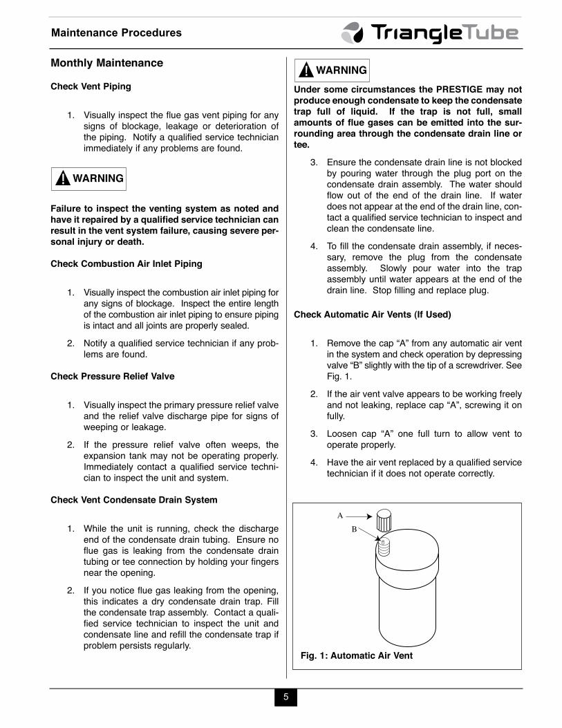
Monthly Maintenance
Check Vent Piping
1. Visually inspect the flue gas vent piping for anysigns of blockage, leakage or deterioration ofthe piping. Notify a qualified service technicianimmediately if any problems are found.
Failure to inspect the venting system as noted and
have it repaired by a qualified service technician can
result in the vent system failure, causing severe per-
sonal injury or death.
Check Combustion Air Inlet Piping
1. Visually inspect the combustion air inlet piping forany signs of blockage. Inspect the entire lengthof the combustion air inlet piping to ensure pipingis intact and all joints are properly sealed.
2. Notify a qualified service technician if any prob-lems are found.
Check Pressure Relief Valve
1. Visually inspect the primary pressure relief valveand the relief valve discharge pipe for signs ofweeping or leakage.
2. If the pressure relief valve often weeps, theexpansion tank may not be operating properly.Immediately contact a qualified service techni-cian to inspect the unit and system.
Check Vent Condensate Drain System
1. While the unit is running, check the dischargeend of the condensate drain tubing. Ensure noflue gas is leaking from the condensate draintubing or tee connection by holding your fingersnear the opening.
2. If you notice flue gas leaking from the opening,this indicates a dry condensate drain trap. Fillthe condensate trap assembly. Contact a quali-fied service technician to inspect the unit andcondensate line and refill the condensate trap ifproblem persists regularly.
WARNING
Under some circumstances the PRESTIGE may not
produce enough condensate to keep the condensate
trap full of liquid. If the trap is not full, small
amounts of flue gases can be emitted into the sur-
rounding area through the condensate drain line or
tee.
3. Ensure the condensate drain line is not blockedby pouring water through the plug port on thecondensate drain assembly. The water shouldflow out of the end of the drain line. If waterdoes not appear at the end of the drain line, con-tact a qualified service technician to inspect andclean the condensate line.
4. To fill the condensate drain assembly, if neces-sary, remove the plug from the condensateassembly. Slowly pour water into the trapassembly until water appears at the end of thedrain line. Stop filling and replace plug.
Check Automatic Air Vents (If Used)
1. Remove the cap “A” from any automatic air ventin the system and check operation by depressingvalve “B” slightly with the tip of a screwdriver. SeeFig. 1.
2. If the air vent valve appears to be working freelyand not leaking, replace cap “A”, screwing it onfully.
3. Loosen cap “A” one full turn to allow vent tooperate properly.
4. Have the air vent replaced by a qualified servicetechnician if it does not operate correctly.
WARNING
5
AB
Fig. 1: Automatic Air Vent

6-Month Maintenance
Check Water and Gas Piping
1. Remove the boiler front jacket panel and perform agas leak inspection per steps 1 through 6 of theOperating Instructions on page 7. If gas odor orleak is detected, immediately shut down the unitfollowing procedures on page 7. Call a qualifiedservice technician.
2. Visually inspect for leaks around the internal boilerwater connections and around the heat exchanger.Visually inspect the external system piping, circula-tors, and system components and fittings.Immediately call a qualified service technician torepair any leaks.
Have leaks fixed at once by a qualified service tech-
nician. Failure to comply could result in severe per-
sonal injury, death or substantial property damage.
Operate Pressure Relief Valve
1. Before proceeding, verify that the relief valveoutlet has been piped to a safe place of dis-charge, avoiding any possibility of scalding fromhot water.
To avoid water damage or scalding due to valve
operation, a discharge line must be connected to the
relief valve outlet and directed to a safe place of dis-
posal. This discharge line must be installed by a
qualified service technician or heating / plumbing
installer in accordance with the PRESTIGE installa-
tion manual. The discharge line must be terminated
so as to eliminate possibility of severe burns or
property damage should the valve discharge.
WARNING
WARNING
2. Read the temperature display and pressuregauge to ensure the system is pressurized. Liftthe relief valve top lever slightly, allowing water torelieve through the valve and discharge piping.
3. If water flows freely, release the lever and allowthe valve to seat. Watch the end of the reliefvalve discharge pipe to ensure that the valvedoes not weep after the line has had time todrain. If the valve weeps, lift the lever again toattempt to clean the valve seat. If the valvedoes not properly seat and continues to weepafterwards, contact a qualified service techni-cian to inspect the valve and system.
4. If the water does not flow from the valve whenyou lift the lever completely, the valve or dis-charge line may be blocked. Immediately shutthe unit down per the instructions on page 7.Call a qualified service technician to inspect thevalve and system.
Maintenance Procedures
6

Operating Instructions
7
WARNING
FOR YOUR SAFETY READ BEFORE LIGHTING
OPERATING INSTRUCTIONS
TO TURN OFF GAS TO APPLIANCE
1. STOP! Read the safety information above on
this label. This appliance is equipped with an
ignition device which automatically lights the
burner. DO NOT try to light the burner by hand,
2. Set room thermostat(s) to lowest setting. Turn
the external manual gas valve handle clockwise
“CLOSE” (valve handle shall be per-
pendicular to gas piping)
3. Turn the service switch on the PRESTIGE con-
trol panel OFF.
4. Remove the front jacket panel on the unit.
5. Turn the external manual gas valve handle count-
er clockwise to “OPEN” gas supply
(valve handle shall be parallel to gas piping).
6. Wait five (5) minutes to clear out any gas. If you
then smell gas in the jacket enclosure or around
the unit, STOP! Follow “B” in the safety infor-
mation above. If you don’t smell gas, go to the
next step.
7. Turn the service switch on the PRESTIGE con-
trol panel “ON”.
8. Set room thermostat(s) to desired setting(s).
9. The PRESTIGE control panel display will show
a sequence of numbers (0,1,2,3,4,etc.) as the left
digit. Sequence digit 3 or 4 indicates the boiler is
firing. Sequence digit 0 means there is no call for
heat (all external thermostats are satisfied)
10. If the unit will not operate with a call for heat and
the system piping is not hot, follow the instruc-tions “To Turn Off Gas to Appliance”, belowand call your service technician or gas supplier.
11. Replace the front jacket panel. Make sure the panel is
seated firmly in place and all mounting screws are
tighten.
If you do not follow these instructions exactly, a fire or explosion mayresult causing property damage, personal injury or loss of life.
1. Set the room thermostat to lowest setting.
2. Turn the service switch on the PRESTIGE con-
trol panel to “OFF”
3. Turn the external manual gas valve handle clock-
wise to “CLOSE”.
A. This appliance does not have a pilot. It is
equipped with an ignition device which automat-
ically lights the burner. DO NOT try to light the
burner by hand.
B. BEFORE OPERATING, smell all around the
appliance area for gas. Be sure to smell next to
the floor because some gas is heavier than air and
will settle on the floor.
WHAT TO DO IF YOU SMELL GAS
• Do not try to light any appliance.
• Do not touch any electric switch; do not use
any phone in your building
• Immediately call your gas supplier from a
neighbor’s phone. Follow the gas supplier’s
instructions.
• If you cannot reach your gas supplier, call the
fire department.
C. Use only your hand to turn the external manual gas
valve. Never use tools. If the valve will not turn
by hand, don’t try to repair it; call a qualified serv-
ice technician. Force or attempted repair may result
in a fire or explosion.
D. Do not use this appliance if any part has been
under water. Immediately call a qualified service
technician to inspect the appliance and to replace
any part of the control system and any gas con-
trol which has been under water.
SECTION IV - OPERATING INSTRUCTIONS
8
Boiler Control Display
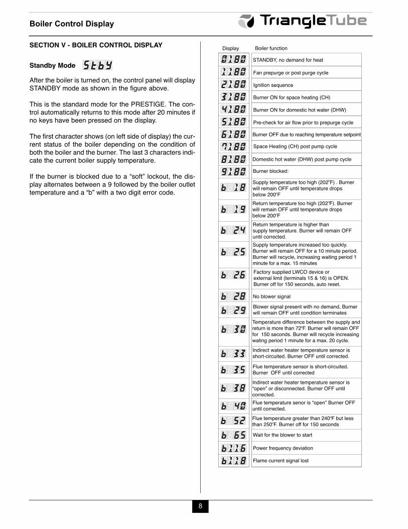
SECTION V - BOILER CONTROL DISPLAY
Standby Mode
After the boiler is turned on, the control panel will displaySTANDBY mode as shown in the figure above.
This is the standard mode for the PRESTIGE. The con-trol automatically returns to this mode after 20 minutes ifno keys have been pressed on the display.
The first character shows (on left side of display) the cur-rent status of the boiler depending on the condition ofboth the boiler and the burner. The last 3 characters indi-cate the current boiler supply temperature.
If the burner is blocked due to a “soft” lockout, the dis-play alternates between a 9 followed by the boiler outlettemperature and a “b” with a two digit error code.
StbY STANDBY, no demand for heat
Fan prepurge or post purge cycle
Ignition sequence
Burner ON for space heating (CH)
Burner ON for domestic hot water (DHW)
Pre-check for air flow prior to prepurge cycle
Burner OFF due to reaching temperature setpoint
Domestic hot water (DHW) post pump cycle
Space Heating (CH) post pump cycle
Burner blocked:
Supply temperature too high (202 F) . Burner will remain OFF until temperature drops below 200 F Return temperature too high (202 F). Burner will remain OFF until temperature drops below 200 F Return temperature is higher than supply temperature. Burner will remain OFF until corrected. Supply temperature increased too quickly. Burner will remain OFF for a 10 minute period. Burner will recycle, increasing waiting period 1 minute for a max. 15 minutes Factory supplied LWCO device or external limit (terminals 15 & 16) is OPEN. Burner off for 150 seconds, auto reset.
0 1 1 8 0 1 8 0 1 8 0 1 8 0 1 8 0 1 8 0 1 8 0 1 8 0 1 8 0 1 8 0
2 3 4 5 6 7 8 9
1 8 b
1 9 b
2 4 b
2 5 b
2 6 b
2
Display Boiler function
No blower signal Blower signal present with no demand, Burner will remain OFF until condition terminates Temperature difference between the supply and return is more than 72 F. Burner will remain OFF for 150 seconds. Burner will recycle increasing wating period 1 minute for a max. 20 cycle.
Flue temperature sensor is short-circuited. Burner OFF until corrected
Flue temperature senor is “open” Burner OFF until corrected. Flue temperature greater than 240 F but less than 250 F. Burner off for 150 seconds
Wait for the blower to start
8 b 2 2 9 b
3 0 b
35b
4 0 b
Indirect water heater temperature sensor is short-circuited. Burner OFF until corrected.
Indirect water heater temperature sensor is“open” or disconnected. Burner OFF until corrected.
3 3 b
38b
5 2 b 6 5 b
Power frequency deviation 1 1 6 b Flame current signal lost 1 8 b 1

9
Boiler Control Display
SETTING THE BOILER PARAMETERS
Parameter Mode
To access PARAMETER mode when the system is inSTANDBY mode, press the MODE button once.
To scroll through the list of parameters, simply press the“STEP” button. To modify a parameter value, use the +or - keys. Then press “STORE” to save the value youjust changed. The display flashes once to confirm thedata has been saved.
To activate the parameters you changed, press MODEonce more (which brings you into INFORMATIONmode). However, if you do not press a key, the systemreturns to STANDBY mode after 20 minutes and auto-matically enables the changes.
ARAP
Note 1: This parameter is factory set to 140ºF. It is
important to note the control adds 46ºF to this setting,
therefore the actual domestic hot water boiler setting is140ºF + 46ºF = 186ºF.
Note 2: This parameter should not be changed from thefactory setting of 01. The performance of the DHW willbe affected and can become unreliable.
Note 3: This parameter should not be changed from thefactory setting of 01. The performance of the CH(Central/Space Heating) will be affected and canbecome unreliable.
Domestic Hot Water Setting (See Note 1)
Domestic Hot Water Setup (See Note 2)
Space Heating Mode (See Note 3)Maximum temperature in space heating(CH) mode. In applications using an outdoor sensor, this is the boiler outlet target temperature at or below an outdoor temperature of 0 F
1.21400101
81 0
ARA
3
4
P
.
.
.
.
MODE
STEP
STEP
STEP
STEP
Key: Display
Key: Display
Description of parameters
Pressing MODE once

Boiler Control Display
10
ACCESSING BOILER INFORMATION
Information Mode
To switch from STANDBY mode to Information mode,press MODE twice.
Press STEP until the system displays the informationyou need. The decimal point located behind the firstposition flashes to indicate that the boiler is in INFOmode.
NFOI The ignition counters and burner hours aresplit into three two digit numbers. For example:
Write the numbers down from left to right toarrive at 123,456 CH ignitions.
In the INFO Mode a temperature reading of -22
typically indicates an “open” circuit. A tempera-
ture reading of 240 typically indicates a short-
circuit.
NOTICE
NOTICE
ARAPMODE
NFOIMODE
Key: Display
Pressing MODE once
Pressing MODE twice
J 12.34.56
Display DigitSegments
Information Mode Items

Boiler Control Display
11
Error (Hard Lockout) Mode
If a system fault occurs while the boiler is running, thesystem goes into lockout and the display starts to flashwith the first digit as an E and the next two digits repre-sent the fault code.
For a detailed description of the error codes, referencethe PRESTIGE Trouble Shooting Guide.
During a hard lockout or low water condition the
boiler will not re-start without service. If the
heating system is left unattended in cold weath-
er appropriate safeguards or alarms should be
installed to prevent property damage.
Boiler Freeze Protection Feature
The boiler control has a freeze protection feature built in.This feature monitors the boiler temperature andresponds as follows when no call for heat is present.
- 46ºF Boiler circulator is ON
- 38ºF Boiler circulator is ON and burner operates
at low fire.
- 50ºF Burner OFF and boiler circulator operates
for approximately 10 minutes.
The boiler freeze protection feature is disabled
during a Hard Lockout, however the CH circula-
tor will operate.
During a hard lockout or low water condition the
boiler will not re-start without service. If the heat-
ing system is left unattended in cold weather
appropriate safeguards or alarms should be
installed to prevent property damage.
WARNING
CAUTION
CAUTION
Gas valve harness not properly connected
Failed ignition after 5 attempts
Power supply lost after lockout occured
Internal control failure
Internal control failure
E E 0 2 03 0 4
0 8 0 9
E E
E
Display Hard Lockout
Internal control failure 0 5 E Internal control failure 0 6 E Internal control failure 0 7 E
Flame detected prior to burner startup E 0 0
Internal control failure
External limit (terminals 13 & 14) is OPEN
Blower signal does not reset to zero
No blower signal present
Supply Temperature sensor is short circuited
1 1 1 2
1 5 1 6
2928
E
E E
EE
E Flue Temperature exceeds 250 F52E Internal control error - failure to read parameters
61
E
Return Temperature sensor is short circuited
Supply Temperature sensor is OPEN
Return Temperature sensor is OPEN
Internal control failure
Internal control failure
Inadequate power supply to the fan
EE
3132
3637
44
60
65
EE
E
EE
Flue Temperature sensor is short circuit
40E
Return Temperature exceeds 212 F
Supply Temperature increased too rapidly
Internal control failure
Contact Triangle Tube Service Department
Internal control failure
Internal control failure
Internal control failure 1 7
1 9
25
1 3
E
E
E
E
Supply Temperature exceeds 212 F 1 8 E
Return Temperature is higher than supply temperature24E
E 1 4
Flue Temperature sensor is OPEN
35E
E Internal control failure15E Supply or Return Temperature sensor drift
23
Invalid power frequency
Supply or Return Temperature failure
Supply or Return Temperature not changing
1311111
22
24
E
EE

12
Replacement Parts
5
9
81
3
5
2
6
7
Fig. 2: Jacket Components - PRESTIGE
13
Replacement Parts
8
5
9
23
4
4
67
1
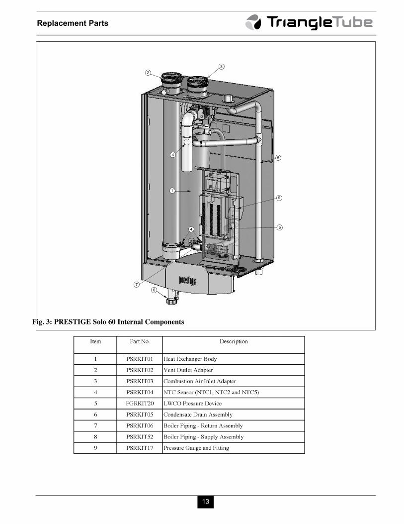
Fig. 3: PRESTIGE Solo 60 Internal Components

14
Replacement Parts
Fig. 4: Internal Components - PRESTIGE 110

15
Replacement Parts
8
54
4
10
9
7
1
3
2
6
Fig. 5: Internal Components - PRESTIGE 175/250

16
Replacement Parts
8
7
10
1
23
4
45
6
9
Fig. 6: Internal Components - PRESTIGE 399

17
Replacement Parts
15
13
11
8
1510
12
14
9
32
Fig. 7: PRESTIGE Excellence Internal Components

18
Replacement Parts
Fig. 8: Burner Components - PRESTIGE 60/110/175/250 and EXCELLENCE
19
Replacement Parts
7
6
9
1
2
10
12
13
4
3
5
8
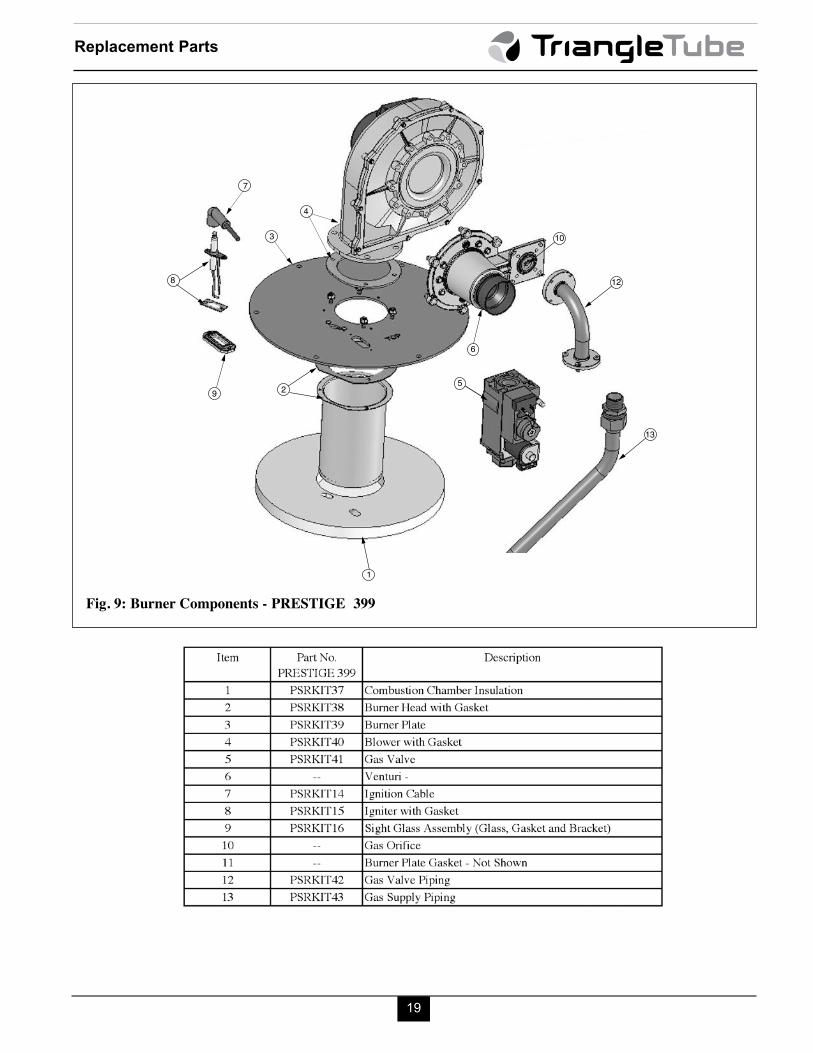
Fig. 9: Burner Components - PRESTIGE 399

20
Replacement Parts
Fig. 10: Electronic Components - PRESTIGE

Additional quality water heating equipment available from Triangle Tube
Brazed Plate Heat Exchangers
Phase III Indirect Fired Water Heaters
Maxi-flo Pool and Spa Heat Exchangers
Freeway Center - 1 Triangle Lane
Blackwood, NJ 08012
Tel: (856) 228 8881 - Fax: (856) 228 3584
E-mail: [email protected]
Member of
Group
- Constructed of high quality corrosion resistant stainless steel (AISI 316)
- Specially designed built-in flow restrictor to assure maximum heat exchange
- Compact and light weight
- Available in 5 sizes that can accommodate any size pool or spa
- Exclusive “tank-in-tank” design
- Stainless steel construction
- Available in 8 sizes and 2 models
- Limited LIFETIME residential warranty
- 15 year limited commercial warranty
- Self cleaning/self descaling design
- For domestic water, snow melting, radiant floor, refrigeration
- Plates made of stainless steel, with a 99.9 % copper and brazed, ensuringa high resistance to corrosion
- Self cleaning and self descaling
- Computerized sizing available from Triangle Tube/Phase III
- Available in capacities from 25,000 BTU/hr to 5,000,000 BTU/hr