presentedat the h convention [ ' t.31 nov
TRANSCRIPT

DIFFERENTIAL TECHNOLOGY IN RECORDING CONSOLES 1723(C-3)
AND THE IMPACT OF TRANSFORMERLESS CIRCUITRY
ON GROUNDING TECHNIQUE
Thomas M. Hay
MCI_ Inc.Fort Lauderdale, FL
Presentedatthe 67th Convention [__'_1980 Oct. 31/Nov.3NewYork
Thispreprint has beenreproduced from the author's advancemanuscript, without editing, corrections or consideration bythe ReviewBoard. TheAES takes no responsibility for thecontents.
Additional preprints may be obtained by sending requestand remittance to the Audio Engineering Society, 60 East42nd Street, New York, New York 10017 USA.
All rightsreserved.Reproductionof thispreprint, oranyportion thereof, is not permitted without direct permissionfrom the Journalof the Audio EngineeringSociety.
AN AUDIO ENGINEERING SOCIETY PREPRINT

"DIFFERENTIAL TECHNOLOGY IN RECORDING CONSOLES AND THE IMPACT
OF TRANSFORMERI_SS CIRCUITRY ON GROUNDING TECHNIQUE"
Thomas M. Hay, Vice President, Engineering, M.C.I., Inc., FortLauderdale, Florida and a Governor of the Audio Engineering Society
Possibly, the least tmderstood problem encountered during the con-struction of a recording studio is the powering and grounding ofthe equipment. While the arts of acoustics, monitoring, and equip-ment design have been studied extensively it se_ns that the art ofstudio powering and grounding has been left to the "Black Art"category.As an appendix, I have included a short comparative analysis ofperformance of Differential Technology to Transformer Technology.While many readers will sigh relief that their opinions concerningtransformers have been proven true, the remainder of the readerswill have their eyes opened.
2he Transformerless Technology is here now!
Technological advances in equipment interconnect design during the pasttwo years dictate we remove the science of grounding from the archives ofmystical magic and bring it Into the daylight. To this end I have writtenthe following paper covering basic powering and grounding practices which Ihave learned over the years and have applied with complete success in everyinstance. I l_ave attempted to write in layman's terms such that no degreein math_lmtics or electrical engineering will be required to follow the guide-lines and procedures outlined.
THE A.C. LINE
Ail hun, buzz, and many of the R.F. problems in a studio installationstart with the A.C. mains and their relation to ground. The A.C. power wiring,light fixtures, power cords, and virtually every piece of equipment connectedto the A.C. Line projects an electrostatic and an electromagnetic field which maybe picked up by every audio wire and circuit in the studio. Additionally, theA.C. mains are a carrier of many forms of Radio Frequency Interference (R.F.I.)generated by electric motors, S.C.R. Dimmers, medical equipment, computers, anda host of other appliances in day to day use. To minimize the effect of thesefields on the audio installation, careful, thoughtful design implenlented withextensive quality control of the actual electrical work is essential.
The first step to proper A.C. Power is:
Isolate the studio from the power companyand all general purpose electrical wiringin the building.
2he simplest way to accomplish the isolation is to request the power com-pany to provide a separate power transformer and electrical service from theirservice pole. Most smaller studios in their own building will have no problemwith this, however, in some areas and large buildings it may not be possible.If the power c_npeny can not provide a separate power entry, then you mustobtain an isolation transformer. The isolation transformer should be equipped
1.
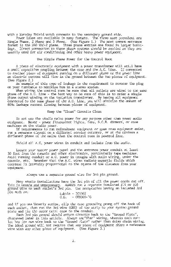
with a Faraday Shield which connects to the secondary ground side.Power Lines are available in many formats. The three most prevalent are
Single Phase, 2 Phase and 3 Phase. (See Figure 1.) The most conmon entranceformat is the 240 VAC-2 phase. Three phase entries are found in larger build-ings. Direct connection to three phase syst_ns shottldbe avoided as they areusually used for air conditioning and other heavy power equipment.
Use Single Phase Power for the Control Room
A piece of electronic equipment with a power transformer will still havea small capacitive coupling between the case and the A.C. Line. If connectedto another piece of equipment running on a different phase or the power linean electric current will flow in the grotmd between the two pieces of equipment.(See Figure 2.)
An example of this type of leakage is the requir_nent to reverse the plugon your turntable to minimize ht_a in a stereo system.
When wiring the control room be sure that all outlets are wired to the samephase of the A.C. Line - the best way to be sure of this is to order a singlephase output winding on tile isolation transformer. By having all eqLtipmentconnected to the same phase of the A.C. Line, you will minimize the amount of60Hz leakage current flowing between pieces of equipment.
Keep the "Clean" Circuits Clean
Do not use the studio mains power for any purpose other than power audioequipment. Never - power flourescent lights, fans, S.C.R. dimmers, or cokemachines on the studio power.
If requirements to run refreshment equipment or game room equipment exist,run a separate circuit on a different service entrance, or at the minimLvnadifferent phase of the mains tim the control room is powered from.
Shield all A.C. power wires in conduit and isolate from the at_Jio.
Locate your master power panel and the entrance power conduit at least30 feet from the console and other electronics, particularly tape machines.Avoid running conduit or A.C. power in troughs with audio wiring, under theconsole, etc. Remember that the A.C. wires radiate magnetic fields whichdecrease in intensity proportional to the square of the distance from yourequipment.
Always use a separate ground wire for 3rd pin ground.
Many studio installations have the 3rd pin of all the power cords cu_ off.This is unsafe and unnecessary. ALWAYS run a separate insulated _j14 or jjl6ground wire to each outlet's 3rd pin. Use receptacles having an isolated 3rd
pin suchas: Hubble- IG5362G.E. - GE8300-IG
and if you use Waverly strips, clip the case grounding prong off the back ofeach socket, then run the 3rd wire (GRN) of the strip to your system groundplate and tie the outer metal case to the conduit.
Each 3rd pin ground should return directly back to the "Ground Plate",discussed later in this article. Always use"Star" wiring, wherein each out-let Ires its own wire back to the "Ground Plate" rather titan daisy chein wirJ2_g.
The ideal ground will not require that any piece of equipment share a referencewire with any other piece of equipment. (See Figure 3.)
2.

Never let the 3rd pin ground short to the conduit as this will alwaysproduce ground loops. Electricans allow conduits to touch each other, touchwater pipes, and interconnect. Conduit is not a useable ground for audio work.
When the studio wiring is being installed, the studio tect_ician will dowell to have all 3rd pin grounds left unconnected at tl_ ground plate. Then,after the wiring is run, each receptacle can have the 3rd pin ot_n'ed to con-duit to verify isolation - connected to ground - then olin'ed to verify ground.
GROUNDING
Having gotten into the subject of grounds, several key points must beunderstood.
What is Earth?
Earth is correctly used to describe the power company ground. The heavyground wire brought into the breaker box and grounded to the gro_d plate inthe breaker box is "earth". This should be the only interconnect to the worldoutside of the studio. Frequently a ground rod and/or water pipe ground istied at this same point. In most c_nunities, the water pipe ground connectionis a legal requirement.
What is Ground?
Ground is a relative term. Ground is the name we give to the point wewant to call the zero signal reference. It is the zero signal reference onlyif every piece of equipment ties to this exact spot. There rm3stbe one andonly one Ground Point in the entire studio complex. It is to this point thatall 3rd pin grounds, ease grounds, etc. should tie, like the spokes of a bicyclewheel.
Ground should tie to "earth" by one interconnect from the zero signal re-ference node to the power company ground.
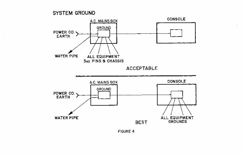
The best point in the control room to make the zero signal reference is aground lug on the mixing console. M.C.I. recording consoles as well as manyothers currently produced have such a ground plate. If such a ground plate isnot available or inadequate use a conventional buss strip available at anelectrical supply. (See Figure 4.)
Alternatively, the ground plate in the fuse box can be used and a singleheavy wire run to the mixing console ground. While this is a rmacheasier sys-tan to implement it will not be as good as having all grounds at the consolewhere signal amplification occurs, and the closer these amplifiers referenceto "Ground", the less they will mmplify ground noise. (See Figure 5.) Forexample, a wire having .01 o_n resistance and carrying 1 millim_p of currentwill generate a voltage of 10 microvolts or a signal that is -100dB below linelevel. If this signal is applied to 8 microphone preamps with 40dB of gainit will he -42dBv, or 23dB above tape noise.
Grounding the Equipment Rack
Acceptable performance can usually be achieved from the typical equipmentrack if a single heavy ground is brought back from each power receptacle in therack to the ground point. When doing this the following three precautionsshould be observed:
1. Be sure that the power line input of each piece of equipment mountedin the rack is transformer isolated. If not, connect to power throughan isolation transformer.
2. Any piece of equipment which is not balanced in and out should be
3.

isolated from the rack and a separate ground wire taken back to theground point. (Note: if done correctly the 3rd pin will usually beadequate. )
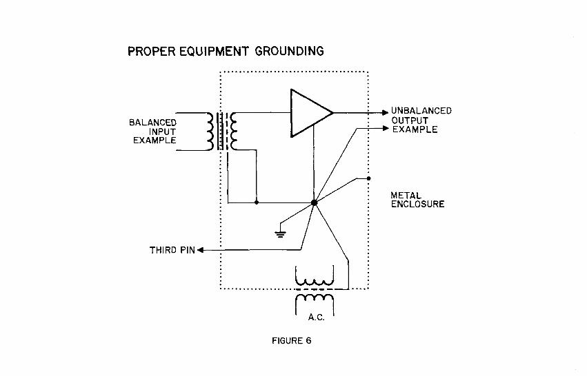
3. Each piece of equipment installed in the rack should follow correctgrounding and shielding design:
To properly ground and shield a piece of electronicequipment, tie the case, the 3rd pin earth (or groundreference), and the electronics ground together atonly one point. The point on the electronics groundshould be the zero potential point which is thatpoint from which all current flows to the circuits.(See Figure 6.)
If you find a piece of rack equipment which does not follow thisgrounding format, be cautious when wiring it into the system. Youmay find that electrical isolation from the rack or modificationof the unit is necessary.
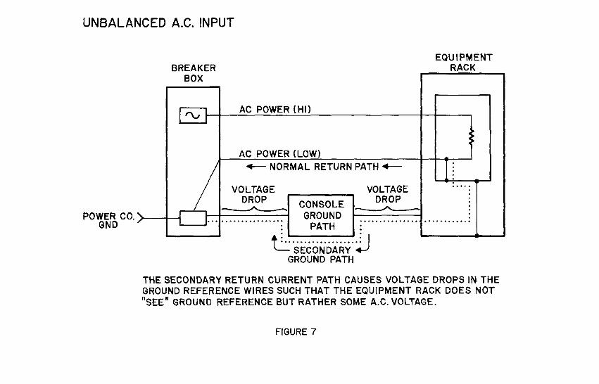
A violation of rule 1 can cause a power/ground loop if the low side of theA.C. Line is tied to chassis. (See Figure 7.) If the equipment is also unbal-anced in/out as most any low cost unit not having a power transformer will be,then the low side of the line is linked back thru the e_tire audio signal systemand A.C. power can actually be fed thru the console circuits to ground causing50/60Hz modulation of the console ground. Always remember that the Iow side ofthe A.C. Line has current from each device flowing thru it. Thus, there isusually a voltage drop of a volt or more between Ground and the Iow side of theA.C. Line.
A violation of rule 2 can cause A.C. leakage current from every piece ofequipmemt in the rack to be superimposed on the audio low side as an A.C. volt-age or hun.
What about the "Carry In" Equipment?
Frequently mixers or groups will bring their own electronic device andwant to connect it into the system. Since much of this carry in equipmentwill be unbalanced and may not have a power transformer, the console patch bayshould have several 1:1 line transformers available on patch. Usuallyisolating the inputs and outputs of the piece of equipment will solve most hunand R.F. probl_ns if the control room power circuits are properly done.
SHIELDING AND THE AUDIO INTERCONNECTS
Once we have all the equipment connected to power and to the ground refer-ence, we must interconnect the signal lines.
The best installation procedure to follow when interconnecting the studioequipment is:
Step 1. Cormect Control Monitor System and Console. Apply power and withall faders closed, monitoring the 2 mix bus with the mix masterfader and monitors at full level - listen for hun, buzz, and R.F..
Only when you are satisfied with the system noise character goto Step 2.
Step 2. Connect noise reduction units and rm_ltitracks to the console oneat a time. Apply power and with appropriate channel faders atncnlirml level and machines in Input, check for hun, buzz, and R.F..Only when you are satisfied with the noise character, go to Step 3.
4.

Step 3. Connect one piece of peripheral equipment at a time to theconsole. Monitor the equipment at signal levels and verifyoperation and acceptable hum, buzz, and R.F..
By following the above three steps you will be able to pin point problemconnections as they are made, saving much work and time.
Careful adherence to the following shielding and signal interconnect ruleswill provide a sound basis to prevent most of the hum, buzz, R.F., and cross-talk problems usually encountered when wiring a new studio.
Shields should connect to signal ground atthe earth tie point on the signal source end.
/his statanant is important because of three critical current paths whichneed to be optimized. (See Figure 8.) Three sources of signal being impressedon the stzield of a cable are; the capacitive cot_pling between the si_al wiresinside the shield and the shield itself, the extraneous electrostatic fieldscutting the shield, and the point to which the shield is tied.
Any signal within the shield is capacitively coupled to the shield andcauses a current to flow in the shield. This current must ultimately returnto the source of the signal, either thru a direct connection to that source'sground or via the entire ground system, if tied to the receiving end. Sincethe capacitive coupling impedance goes down as frequency goes up, an incor-rectly grounded slzield will cause excessive high frequency crosstalk in the sys-tan by generating a voltage drop in the ground systan.
The shield is also carrying a current radiated into the shield from A.C.and R.F. fields near the shield. These currents need to be returned to earth
by the shortest route and thru the fewest signal grounds as they will causea voltage drop on a signal ground. This voltage drop will appear on the signaloutput of the electronics referenced to the signal ground.
Lastly, the shield must be at the zero potential of the si_al within theshield or the shield will itself become a source of radiation onto the signallines within.
Every signal line should have its own shield
If signal lines are put witllin a common shield they will capacitivelycouple to each other. If shields are shorted together other than at the signalreference point, then they will share coupled signal currents and will not be atrue shield to the signal line within since the finite resistance of the shieldwill cause a voltage drop lifting the shield above the signal reference.(See Figure 9.)
In high R.F. areas, the "receiving end" of a shieldedwire (that end not tied directly to signal ground)should be tied thru a 0.01 uf capacitor to Signal/Earth Ground.
At R.F. frequencies, this 0.01 uf capacitor will appear as a short lower-ing the effective shield impedance to ground. A 24 track tape recorder con-nected thusly will have 0.5 uf of the capacitance between the two systams whichis about 530 ohms at 60Hz - not a significant ground loop problem.
5.

In s_n_ry, when interconnecting individual pieces of studio equit_nent,there are three possible input/output circuit configurations; unbalanced,balanced, and differential. These can be connected nine different ways.
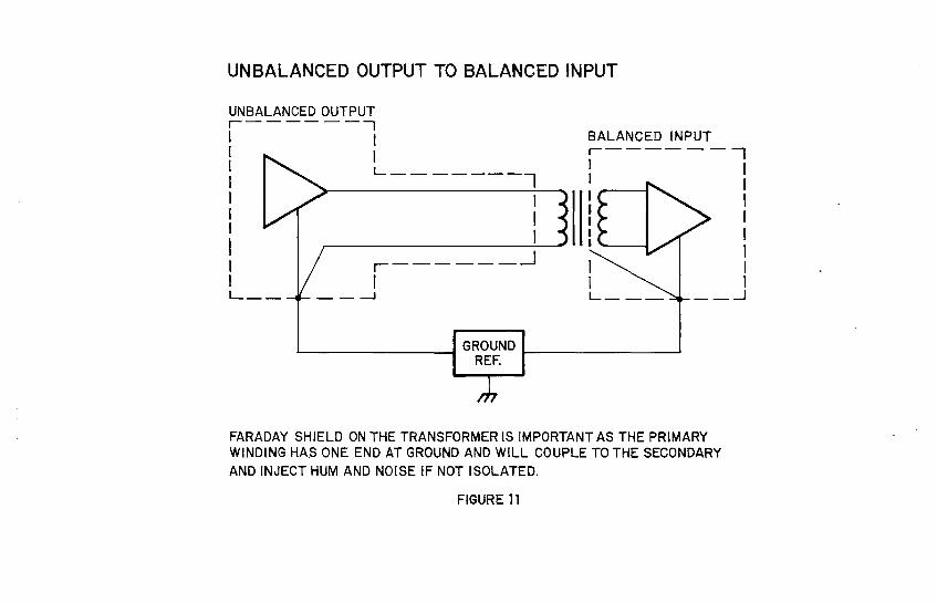
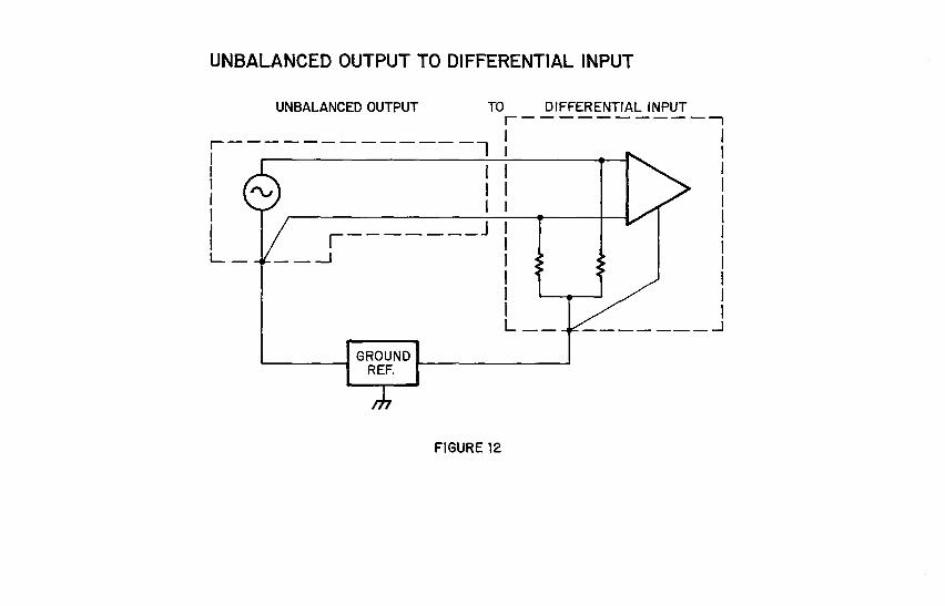
Figures 10 thru 18 diagram each of the nine possible interconnect schemes.I have noted particular considerations of each interconnect with tileapplicabledrawing.
Care should be t_en when reviewing each type of interconnect. The groundpoints indicated need to be connected as shown in the drawings. Whel_ inter-connecting several inputs or outputs from the same unit, only one gronnd reaference wire should be needed to that unit.
6.

APPENDIX A
A discussion of current "Differential Technology" being used in profes-sional recording equitxnent.
Currently, "Differential Technology" is being used to replace virtuallyevery audio transformer in M.C.I. equipment. Many other manufacturers arefollowing similar trends. While the most r_narkable improvements in signalprocessing have been a result of replacing microphone and tape head trans-formers with low noise instrunentation amps, the use of differential inputsand active differential line drivers also warrants review. The followingis only a brief discussion touching on basic design philosophies and signif-icant factors of improved performance demonstrated with conloarative data samples.
THE LINE INPUT
Most manufacturers are using a differential line input amplifier consistingof a classic single op-a_p design. (See Figure 19.) This circuit can pro-vide improved performance in every par_neter including C.M.R.R. (Conmon ModeRejection Ratio) which is typically 70dB or more at all frequencies from 10Hzto 1 megahertz.
The ca_raonmode signal is that signal comnon toboth inputs of an amplifier. The rejection ratiois a ntm_oer ec_i_ir _ the audio signal gain tothe conmon mode signal gain - a larger nunber isbetter.
Conments on the Circuit (Figure 19.)
A few connmnts on the configuration are in order. At M.C.I., we choseto use a Non-Polar capacitor on the output of the circuit for interstagecoupling and D.C. couple all input/feedback circuits. This D.C. coupling pro-duces the best pulse/transient characteristics. A constraint placed on theuse of this circuit is that any D.C. difference on the input will reduce head-room. In this circuit, _ volt of D.C. on the input will reduce the headroomby idb since the circuit has 23db of headroom this is not a problem.
The input circuit comprised of the 1K and 1000pf capacitors forms anR.F. trap to stop R.F. entering the module.
The circuit shown in Figure 19. has a maxirmmn 'znPut level of +27dBv whenpowered on _+18V and a dynamic range of over 128dB with _neasurable distortion.
THE MICROPHONE PREAMPS
Several manufacturers are now offering transfonnerless microphone pre-amps. Most are balanced input instrunentation amplifiers with specially de-signed low noise transistor pairs used for the high gain front stage. It isthe differential preamps, I am ccmparing to transformers.
Several articles written in the past year have expo_ded on the virtuesof the transformerless preamp so I will only briefly recap and detail thefactors I believe are worth noting.
Distortion
Typical microphone transformer iow frequency distortion is 0.1% risingrapidly above -10dBv input level. Thm overall usable dynamic range of atypical microphone transformer is approximately 75db. The usable dynamic rangeof the M.C.I. preamp is 150 to 155dB since distortion is less than 0.03% atany input level up to +16dBv and any audio frequency (at +16dBv in the output isat clipping).
7.
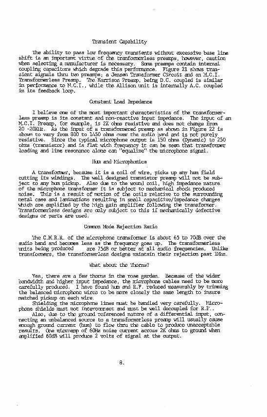
Transient Capability
The ability to pass low frequency transients without excessive base lineshift is an in_portant virtue of the tranformerless preamps, however, cautionwhen selecting a manufacturer is necessary. Some preamps contain internalcoupling capacitors wh'__h degrade this performance. Figure 21 shows tran-sient signals thru two preamps; a Jensen Transformer Circuit and an M. C.I.Transformerless Preamp. The Harrison Preamp, being D.C. coupled is similarin performance to M.C.I., while the Allison onit is internally A.C. coupledin its feedback loop.
Constant Load Impedance
I believe one of the most inl0ortant characteristics of the transformer-less preamp is its constant and non-reactive input impedance. The input of anM.C.I. Preamp, for example , is 2K o_ns resistive and does not change from20 -20KHz. As the input of a transformered preamp as shown in Figure 22 isshown to vary frcm 800 to 1450 ohms over the audio band and is not purelyresistive. Since the typical microphone output is 150 ohms (Dynamic) to 250ohms (transistor) and is flat with frequency it can be seen that transformerloading and line resonance alone can "equalize" the microphone signal.
Hun and Microphonies
A transformer, because it is a coil of wire, picks up any hun fieldcutting its windings. The well designed transistor preamp will not be sub-ject to any hun pickup. Also due to the wound coil, high in_pedancenatureof the microphone transformer it is subject to mechanical shock producednoise. This is a result of motion of the coils relative to the surroundingmetal case and lmninations resulting in small capacitive/impedance changeswhich are amplified by the high gain amplifier following the transformer.Transformerless designs are only subject to this if mechanically defectivedesigns or parts are used.
Comnon Mode Rejection Ratio
The C.M.R.R. of the microphone transformer is about 65 to 70dB over theaudio band and becomes less as the frequency goes up. The transformerlessunits being produced are 75dB or better at all audio frequencies. Unliketransformers, the transformerless designs maintain their rejection past 1Mhz.
What about the Thorns?
Yes, there are a few thorns in the rose garden. Because of the widerbandwidth end higher input impedance, the microphone cables need to be morecarefully produced. I have found hun and R.F. reduced measurably by trinmingthe balanced microphone wires to be more closely the same length to insurematched pickup on each wire.
Shielding the microphone lines must be handled very carefully. Micro-phone shields mast not interconnect end must be well decoupled for R.F..
Also, due to the ground referenced nature of a differential input, con-necting an unbalanced source to a transformerless preamp will usually causeenough ground current (hun) to flow thru the cable to produce unacceptableresults. One microanp of 60Hz noise current across 2K ohms to ground whenamplified 60dB will produce 2 volts of signal at the output.
8.

THE LINE OUYPUT
Differential Line Outputs have been used for several years. Their twoobvious advantages are the balanced differential signal line and the abilityto get 6dB more output level from the same powor supply rails. Until recently,the problem has been that few if any have provided the ability to operatebalanced or unbalanced without a change in output level or distortion.
The classic differential driver wherein one side is driven with an
inverted signal is shown in Figure 23. Shorting either side results in a 6dBreduction of output level and usually distortion, oscillation, and eventualop-an_ failure. Thus, tbis circuit is limited to balanced line use only -not very realistic in the real world of recording studios.
Ihe circuit used by M.C.I. is examined in Figure 24. The unique portionof this circuit is the cross coupled output sensing feedback. In an effort tomake the operation understandable, I have provided a node voltage chart forthe 3 modes of output operation.
Comparison
In comparing the differential output smplifier I have provided two setsof square wave photos. (See Figure 25.) These photos exhibit the outputcharacteristics of M.C.I. 's Active Differential Output Amplifier, M.C.I. 's1:1 output transformer used in the 500 A and B Series (the 500 C now useactive differential amp outputs), and the 6dB step up trsnsformer used by somemanufacturers to achieve headroom on + 18V rails.
While the transmission of 15KHz Ts good for all choices, note the degra-dation of the low frequency square wave.
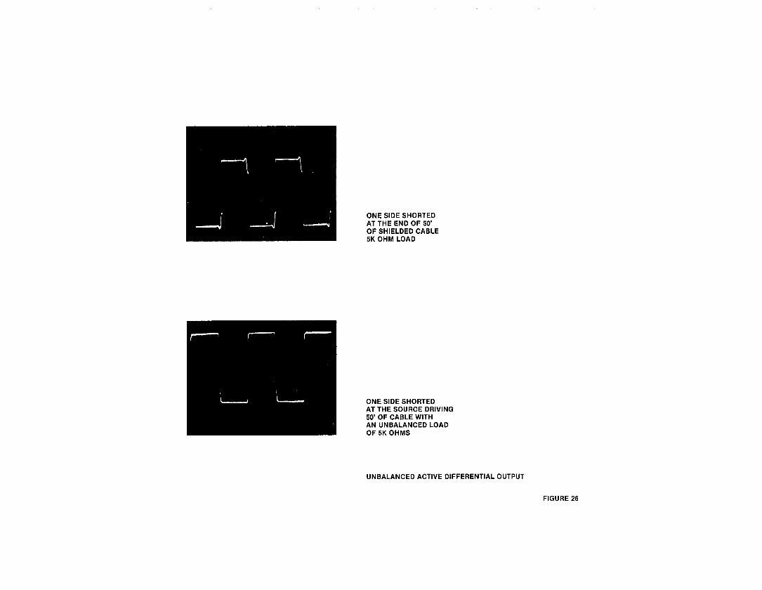
Cautions when using the Active Differential Output
The active differential outputs use either a shut off circuitor use the current limit of the Op-Amp output when working into an
unbalanced load with one side to ground. If this short to ground is at theload, then the turn off or current limit circuits must work thru the cablecapacitance and inductance. 21_ephase shifts (delays) caused by the lumpedinductance/capacitance can cause rise time anomalies. (See Figure 26.)
Whenever running the active differential output into an unbalanced loadshort the low side to signal ground at the output (drive) end of the cable,this will provide the path of least impedance to ground and will preventdriving the output current thru the ground reference system.
9.

POWER LINE PHASES
n_ 120 VAC1|
120VAC _ 12OVA
TWO PHASE
SINGLE PHASE THE A.C. SIGNALS ARE 180= OUTOF PHASE WITH EACH OTHER.
--'_/120VAC-,%
120 VAC_,120VAC
JTHREE PHASE
THE A.C. SIGNALS BETWEEN OUTPUTS ARE120=OUT OF PHASE WITH EACH OTHER.
FIGURE 1

A.C. LEAKAGE
SIGNALS IN PHASE SIGNALS OUTOF PHASE
rG rGCLEAK CLEAK
LOW LOW LOW LOWl
'4-- I LEAK
® ®V=O V=2xLINE
FIGURE 2

Fs7
-F
'-7
F1
z,g
a,-7
a:o©
_oa
Fq
mwIll
II
oO,...
_'
>_F
"-]
ct)
"J
_{3
'Z
oo
-
oo
W..lm
o313.
WW
m
0w
omu.l'_
tno
__l
o
0m
o__
o_E
oo
E
_-
wa:
_w_
__w
)-oLU
0w
03
n_
n

[]
FIGURE5
r_UJLIJ
C._
Wn_
Z<gW
_x
mz
,°,°......................
°.......
,.........
*°*.°°°°}
i.1
1o
!i
§,_
I1..
I.i.I
tv'<
rm
13..oa
Lm¿}--
T}--
__
zz
..........
or)
nO
O_
On,'
I..U
_voW
W,q[_
--zo
_)
Ow>
¢,,,s,_
......--.-_23,..2222
_1:7o
_-_
S0
:WO
z
w-"
_00rn
mT'
g°
,,,
O ,,m
0tw
I'-'Li.iW
I-.
>wa:_"
W
Z_
,_wz
_:X_
I.t..
K_
,,_0Z
W_
wm
On.-O
m.-,_
{223
,,,o,,,
W-rr_oo
(..)I.-_=
Z_'
mow
Z
Zo
2C)
o.

rn
................................
:_-_I:_
................................
'W:_W_I
-w,-__
o_
--(
iW
zw_
0w
UJ
n'O_:_
z_o
_.=o
..........:
___o_
............._
_-_-........
I_
o_"(.9
I'>
__
_o
oi
II
IJ
dc__
"'"'
:_-_8
-o
I=
"'I
--h<
T--
I
HHo_
I
_w
P-_
o_
ow,,,_
w=_
,,
_-
>>
"'w
Ipzo
-...................
:_j>
_-_0
"'-
<"'"'-'1
_o,_
j_
-_
ww
:'"=
_"'
UJ
n--II,
--v-I_
:Z
:_
I-"W
.............'"°'**'"'°°'*
--
''''"'*''"
.....°°''"°°"°°°"
_I"

i-rIl.
Zl
O_i.i.
I
wi
O3=
On-
zo_o
0
a_L
_1
z__
uJz
_zG
=__
mr_
fw
_z=
LI_I]
a-I-"
w°'
x_
lh
i
_._w
e0u_
a:·
b.I
4z
Ioo_.-
.J
Io_
_'"'g
om
w0::
---r-
w_
zI--
II_
zI
_._o_._p_
0"'
ZI
LEI__
I--
oZ
)I
od
ow
_-
IL_.1
_-
0_
____.>
.,z,__F
o_O
121
_o
co
hi
01
O-I
'"U
-
ool
=m-
Zw
,,,_n,-
_:
_1
_,_'_
--
r.9n
Z"_
z>
I1
I-_
)_<
{]P
I_1:3_:z
-zI
_=o
.-,o,
nwi
"fy)
,,,71
-r-W<
rF
-"r'
_..O
aI--zLIJ
z_
- El
ILloo
_D
-OW
lo
-1_i
-
![-¢-
zg_<
_,,,
j<[
_.u,,.
Iw
oo=
o
i,,_o zz_
)wI--
I'_
""-
I_-_W
<{o
F_F__J
L=
z0
_--]
_-"' zE
_A
Wz
__1
Io
gl
_I
°i,i
jz:ELLI
r,j'"1
//_Z
LU_
:z:_'
:z:
/\<
::°71
]-o
j>
..LU
n_
Z
mgl
I<
'::'-Z
_zn
ZL
.....__.
I_z.<
nz 0.z,
z-J
_TI
zI
,,i
L.....
Jn-,,,B
mu_
I
oI
w
n0w0z
C._
zz
...I
mI
Z

13.
g3
W_
00.
..._.."'"
g
-,r_o
·.._
°o
z..........
_8
ZO¢
zw
13-
_g,,o
,7,
03O
0r'_
_-
13-
-J_--J
o?
__,]
_._
Wo
_-o_i
Zow
-cz,,,,_
zI-<
_z
gi
ozm
nn
...............................
Z:l-

·O
d::::)
·.°°
°°°,*°hi
*¢_
w<
{z
o.
z_
/.....
Jz
Jo_
W,_
_-
oz
Izo
Zu.io_
WI
_w
._l
n-_
WI
b.
oo_
mo0
Il-
I-
_'
_0
__"
Im-_.
_,
o_
i_
I--_
w
i wpO_l
..._
_._1
I_-<
I--............
Ii.::)
__
:_
z_j
I-...._
JL
<z
0_
_:
w_
Fn
_-w
:·
0I
*'-'""
"'
I(_
:','
_I
IL_
I_',
0_
:_
W
j.u
:w
*_
_l_
II
®'J
IIII
I<
=<
:<
.Il
T8
.................................:_
mi
II
Iz

_.,,,****._,,°°*°*e
·°0.*
00.,e°,_**
z:;_
(_
_!
_-o
o:
0_
o"_:
,-Iw<
z
I"'<
_!........................i
......._<
zoo=
I/)I-I-_
n-%
:)z
Zz>
coQ-
_I
"'w
-I
"'_0
"
,,,g
oI
_>_._
_:Z<
I_-=
_'_-
°<
[I
<::0_
zo
,-
. Zo
I-z..J
w0,_
I___..
o_
__p__.
o,,,_
,,o_
zw_
D-'rW
U.
I.--I
:_0:=--
--1[:3
o.
I-
0
..Jo
_o
<,_i.............................:
7p__o<
_
·I--
:oo
I-.J
Z:
D::
o__,,,
:,_,-
Z·
(Y)g
n,,:
_o0:w
LL
JI-::_
-rZ-
"::
o_wo
+<

-I-ii
f--
_._>
_-zo_
gg_.,,,
-,zm_
I---=
z_
L........
__,,,_
0on
_n-
_<z-,_
O9
o
,_L_._.
_'_=
°==
_
_I__
/I_,,,__-_
.__<_bJv
_UJ
b_
n_o._
II
8z=_,,
,-

_:_L
.........
"I/
II_
_
,/I
i_,,,I
_ot/
I_-_I
o=
-fi-,'!_J
-_I
I2
I_o

ri.-Z
<{
O..J
ZOri
Mil,
:_,'"
',_
..{.D
(D0
mo
,i
{..>I--:=)
Z¥
_-,*-
2_W
_O
J0..
O..
t'M_
.-.i,3
00
tO;:::)
<I:
_l-o
o_
00
I--'
I[---'IJ.Itv'
II,..-.
,...I.i.r'_
E3
0Z
-r-..j
_j

MCI TRANSFORMERLESS PREAMP OUTPUT TRANSFORMER PREAMP OUTPUT
2V P.P. @50 msldv -- 20 Hz SINE WAVE BURST
NOTE: THE BASELINE SHIFT CAUSEDBY LACK OF D.C. RESPONSE.
2V P.P. @ 50 msldiv 20 Hz PULSE BURST
FIGURE 21

MIC TRANSFORMER INPUT Z
_ JE-IIOK-C
150/IOK EG = <1>-I0 DEV <RE.775V>- RL=lOOK <2>-40DEV -
RCNET >R N=56K
- CN=62PF
A160
n-O
w 140
120tl.ln__ Ioo
80z
6O
4O
2O
20 200 2K 20K
FIGURE 22

STANDARDDIFFERENTIAL DRIVER CIRCUIT
(_ -'--*T-INPUT"v'_,
FIGURE 25

_m0zI--
0z
0o
z__5
>,>
>*
_>
>>
>_
>o
Z0
00
0i
oo-r-
i
5'
}'-v
z>>
>>
>>
q.
0co
_I--
"
,z
__>>0
>_
_"'
,_
II,m
I-m,m
co
I-o
LI.I_
._m
__
°>z
IJ-
0>--
zZ
zId..
--0
_z
-_
l0

20 Hz, 2V P.P. 20 Hz, 2V P.P. 20 Hz, 2V P.P.
iNPUT INPUT INPUT
OUTPUT OUTPUT OUTPUT
ACTIVE DIFFERENTIAL OUTPUT, 5K LOAD 1:1 TRANSFORMER, 5K LOAD 1:2 STEP UP TRANSFORMER, 5K LOAD
15kHz, 2V P.P. 15kHz, 2V P.P. 15kHz, 2V P.P.
!
INPUT INPUT INPUT
OUTPUT OUTPUT OUTPUT
ACTIVE DIFFERENTIAL OUTPUT, 5K LOAD 1:1 TRANSFORMER, 5K LOAD 1:2 STEP UP TRANSFORMER, 5K LOAD
FIGURE 25
ONE SIDE SHORTEDAT THE END OF 50'OF SHIELDED CABLE5K OHM LOAD
ONE SIDE SHORTEDAT THE SOURCE DRIVING50' OF CABLE WITHAN UNBALANCED LOADOF 5K OHMS
UNBALANCED ACTIVE DIFFERENTIAL OUTPUT
FIGURE 26