presentacion de moviles modos character
TRANSCRIPT

1 © 2007 Nokia CERFACS / 2007_10_12 /JRa
Characteristic mode analysis: eigenvalue analysis of antenna structures
Jussi RaholaNokia Research Center
October 12, 2007
2 © 2007 Nokia CERFACS / 2007_10_12 /JRa
Outline• Design challenges for mobile phones• What can eigenvalues do for mobile phones?
• Theory of characteristic modes• Ground plane resonance frequencies and resonant modes• How to find optimal antenna positions

3 © 2007 Nokia CERFACS / 2007_10_12 /JRa
Design challenges for mobile phones• Mobile phones have become multimedia computers incorporating the functionalities of digital cameras, video recorders, music players, internet browsers and GPS navigators• The number of radio systems in the phone is increasing
• Cellular radio systems: GSM, WCDMA• Broadband wireless systems: WLAN, WiMAX• Short-range systems: Bluetooth, UWB• Broadcast systems: FM radio, DVB-H
• Each radio system needs at least one antenna• Antennas must have a broadband impedance match, small size and good efficiency
4 © 2007 Nokia CERFACS / 2007_10_12 /JRa
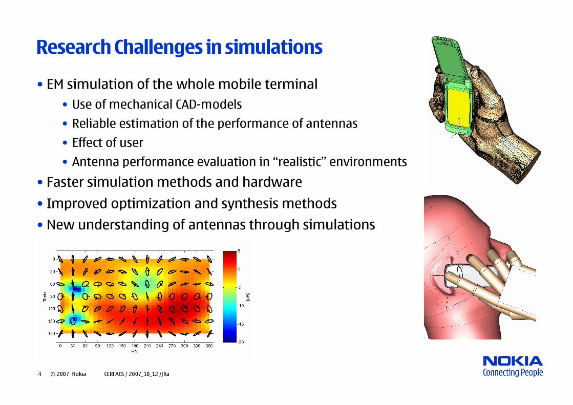
Research Challenges in simulations• EM simulation of the whole mobile terminal
• Use of mechanical CAD-models• Reliable estimation of the performance of antennas• Effect of user• Antenna performance evaluation in “realistic” environments
• Faster simulation methods and hardware• Improved optimization and synthesis methods• New understanding of antennas through simulations
5 © 2007 Nokia CERFACS / 2007_10_12 /JRa
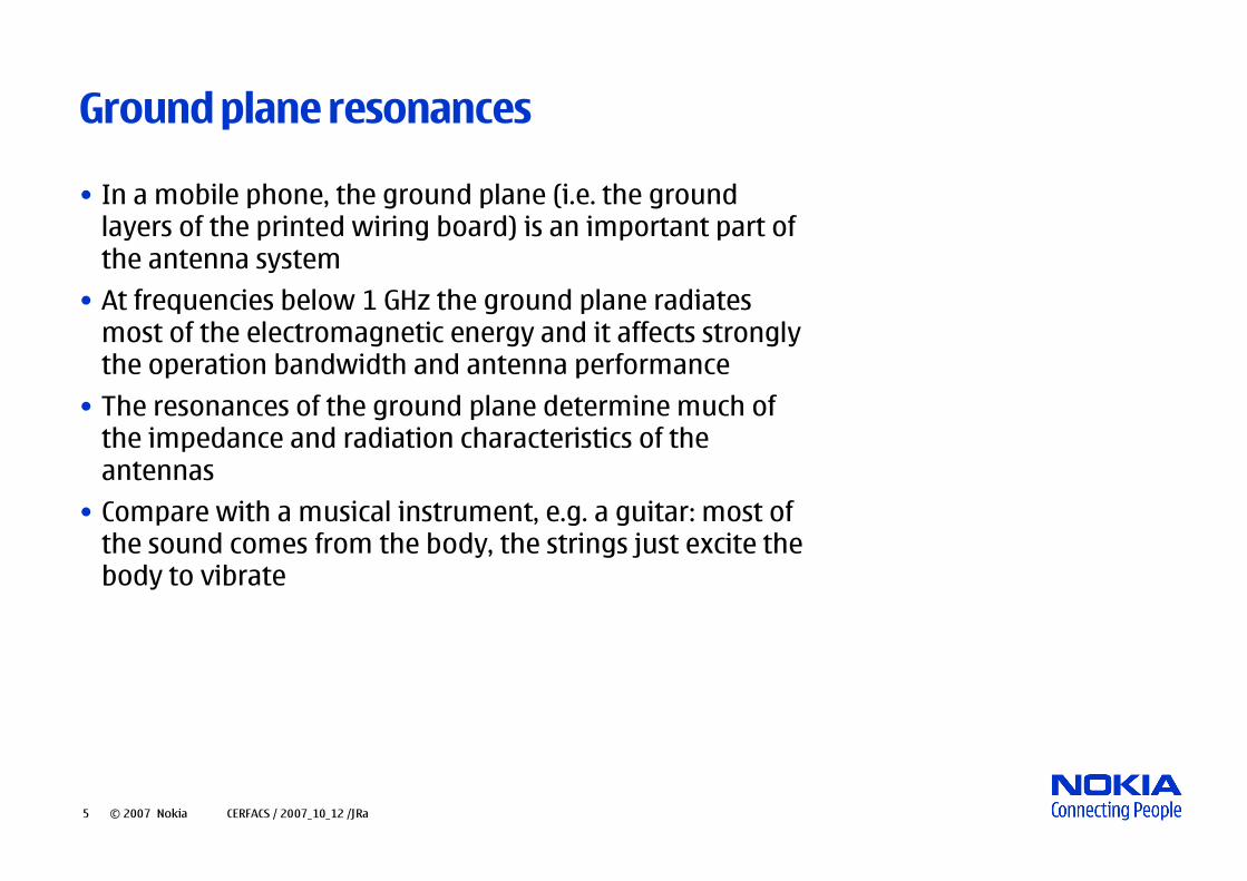
Ground plane resonances• In a mobile phone, the ground plane (i.e. the ground layers of the printed wiring board) is an important part of the antenna system
• At frequencies below 1 GHz the ground plane radiates most of the electromagnetic energy and it affects strongly the operation bandwidth and antenna performance
• The resonances of the ground plane determine much of the impedance and radiation characteristics of the antennas
• Compare with a musical instrument, e.g. a guitar: most of the sound comes from the body, the strings just excite the body to vibrate
6 © 2007 Nokia CERFACS / 2007_10_12 /JRa
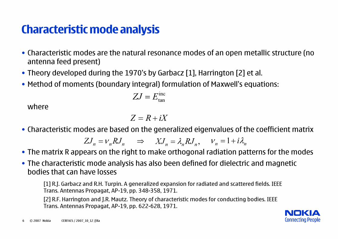
Characteristic mode analysis• Characteristic modes are the natural resonance modes of an open metallic structure (no antenna feed present)
• Theory developed during the 1970’s by Garbacz [1], Harrington [2] et al. • Method of moments (boundary integral) formulation of Maxwell’s equations:
where
• Characteristic modes are based on the generalized eigenvalues of the coefficient matrix
• The matrix R appears on the right to make orthogonal radiation patterns for the modes• The characteristic mode analysis has also been defined for dielectric and magnetic bodies that can have losses
inctanEZJ =
iXRZ +=
,nnn RJXJ λ=
[1] R.J. Garbacz and R.H. Turpin. A generalized expansion for radiated and scattered fields. IEEE Trans. Antennas Propagat, AP-19, pp. 348-358, 1971.[2] R.F. Harrington and J.R. Mautz. Theory of characteristic modes for conducting bodies. IEEE Trans. Antennas Propagat, AP-19, pp. 622-628, 1971.
nnn RJZJ ν= nn iλν +=1⇒

7 © 2007 Nokia CERFACS / 2007_10_12 /JRa
Characteristic values• The analysis gives the characteristic values (eigenvalues) of the resonance modes as a function of frequency
• Also the characteristic modes (current distributions derived from eigenvectors) are computed
•When the characteristic value is close to zero, the mode is at resonance and then the mode would be nicely excited by a plane wave excitation and is also a good radiating mode for antenna applications
• From the characteristic value, compute the characteristic angle α=180°+atan(-λ), at resonance the angle is close to 180°
• This is the argument of the complex number -1/νn• It describes the phase angle between the current Jn and electric field Entan• At resonance the characteristic mode radiates strongly, at 90 or 270 degrees, the mode only stores energy

8 © 2007 Nokia CERFACS / 2007_10_12 /JRa
Characteristic angles for a rectangular ground plane
Length=80 mmLength=140 mm
Mode 2 atresonanceat 2.9 Ghz
Mode 1 atresonanceat 1.3 GHz
width=40 mm, length=100 mm width=40 mm, length varied from 80 to 140 mm

9 © 2007 Nokia CERFACS / 2007_10_12 /JRa
Ground plane modes of a rectangular ground plane (100 x 40 mm)
Mode 1 (λ/2 mode) resonant at 1.3 GHz
Mode 2 (λmode) resonant at 2.9 GHz
Transverse mode

10 © 2007 Nokia CERFACS / 2007_10_12 /JRa
Antenna placement analysis• Find the characteristic modes of the ground plane and their resonant frequencies
• Calculate the electric field of a resonant mode• Place the (patch-type) antenna at the electric field maximum• Try to excite multiple modes to increase the bandwidth• At higher frequencies the antenna starts to modify the pure ground plane modes

11 © 2007 Nokia CERFACS / 2007_10_12 /JRa
Operating bandwidth and impedance match• The antenna is fed by a transmission line (coaxial cable, microstrip line)• If antenna impedance differs from transmission line impedance, signal is reflected back to the amplifier and is not radiated
• Transmission line impedance is typically 50 Ω• Reflection coefficient ρL=V-/V+=(ZL-Z0)/(ZL+Z0)• Scattering matrix element S11= ρL(in dB), also called return loss
Z0 ZL
V+V-
V+
V-= ρL V+

12 © 2007 Nokia CERFACS / 2007_10_12 /JRa
Antenna placement and obtainable bandwidth
A small patch antenna is moved over the ground plane
Both methods indicate thatthe best antenna positions are
at the corners of the ground plane
Electric field 5 mm above the ground plane

13 © 2007 Nokia CERFACS / 2007_10_12 /JRa
Zooming in on the lower part• Another test: 3 mm long vertical probe antenna moved 2 mm over the ground plane. Obtainable bandwidth is given by the inverse of the quality factor Q which is computed as the ratio of susceptance to conductance

14 © 2007 Nokia CERFACS / 2007_10_12 /JRa
Conclusions• Experienced antenna designers know that the best antenna positions are at the corners of a rectangular ground plane
• Characteristic mode analysis explain this as the electric field of the lowest-order characteristic mode has a maximum at the corners
• Results have been verified by computing the obtainable bandwidth of a large number of test antennas but the characteristic mode analysis is faster and gives more insight
• The technology can be used to analyze arbitrary geometries