preface - Интернет-магазин duxe.ruduxe.ru/load/sunfar_vfd_vs500.pdf · this manual...
TRANSCRIPT

PREFACE
Thank you very much for choosing VS500 series of general purpose inverter.
This manual provides guidance of using the inverter safely and carefully, containing introduction of installation, wiring, parameters list, routine maintenance, operating rules and cautions, etc.
In order to make good use of the inverter properly and safely, please read this manual thoroughly before using. It may lead to abnormal operation and failure, reduce using life, even damage the equipment and cause personal injury if you use it wrongly.
This manual is attachment together with the inverter. Please keep it well and it would be available to engineering and installation personnel, repairing and maintaining during the product functioning period. SUNFAR has the right to modify and ameliorate products, data and dimensions without notice, so this manual is updated and all the contents in this manual are subject to change without any notice.
VS500 Series of General Purpose Inverter Operation manual Version: V1.0
Revision Date: JUNE. 2015


Table of Contents 1 INTRODUCTION ……………………………………………………………………………………………
1.1 Model explanation …………………………………………………………………………………… 1.2 Appearance description ………………………………………………………………………………… 1.3 Model of inverter………………………………………………………………………………………… 1.4 Specifications……………………………………………………………………………………………
2 INSTALLATION GUIDELINES…………………………………………………………………………
2.1 Environmental requirements …………………………………………………………………………… 2.2 Disassembly and assembly of the panel………………………………………………………………… 2.3 Disassembly and assembly of the cover board………………………………………………………… 2.4 Dimension of inverter……………………………………………………………………………………
3 WIRING PROCEDURE…………………………………………………………………………………
3.1 Precautions ……………………………………………………………………………………………… 3.2 Wiring of external components ………………………………………………………………………… 3.3 Basic wiring ……………………………………………………………………………………………… 3.4 Terminal of main circuit ………………………………………………………………………………… 3.5 Terminal of Control circuit ………………………………………………………………………………
4 OPERATIONS OF INVERTER AND SIMPLE RUNNING…………………………………
4.1 Operation panel…………………………………………………………………………………………… 4.2 Basic function of panel and methods of operation……………………………………………………… 4.3 List of state monitor parameter ………………………………………………………………………… 4.4 Simple operation…………………………………………………………………………………………
5 PARAMETERS LIST ……………………………………………………………………… 6 DESCRIPTION OF SPECIFIC FUNCTIONS ………………………………………………
6.1 Basic operation parameter unit ………………………………………………………………………… 6.2 Primary application of parameter unit…………………………………………………………………… 6.3 Analog I/O parameter unit ………………………………………………………………………………… 6.4 Digital O/I parameter unit ……………………………………………………………………………… 6.5 Auxiliary running parameter unit ……………………………………………………………………… 6.6 Multi-speed running parameter unit …………………………………………………………………… 6.7 Advanced running parameter unit ……………………………………………………………………… 6.8 Wobble freq. running parameter unit ………………………………………………………………… 6.9 PID control parameter unit ……………………………………………………………………………… 6.10 Communication function parameter units …………………………………………………………… 6.11 Special function parameter unit …………………………………………………………………………
7 SPECIAL FUNCTIONS FOR DRAWING MACHINE……………………………………… 7.1 Overview………………………………………………………………………………………………… 7.2 Selection of dedicated functions of drawing machine ………………………………………………… 7.3 Parameter table of drawing machine dedicated function ([F0.0]=0001)………………………………
3 3 3 5 6 8 8 8 9 10 13 13 13 15 16 18 19 19 20 23 24 25 37 37 42 46 49 53 58 61 63 65 67 69 71 71 71 72

8 Troubleshooting and Measures ………………………………………………………………
8.1 Protective functions and Countermeasures ……………………………………………………………… 8.2 Fault record inquiry……………………………………………………………………………………… 8.3 Reset………………………………………………………………………………………………………
9 MAINTENANCE AND CARE ……………………………………………………………… 9.1 Daily Maintenance……………………………………………………………………………………… 9.2 Damageable parts maintenance………………………………………………………………………… 9.3 Storage………………………………………………………………………………………………… 9.4 After sale services………………………………………………………………………………………
10 USAGE EXAMPLE………………………………………………………………………… 10.1 Panel on-off control, Panel potentiometer setting frequency………………………………………… 10.2 External on-off control mode, external voltage setting frequency…………………………………… 10.3 Multi-speed running, external on-off control mode…………………………………………………… 10.4 Panel on-off control, Panel potentiometer setting frequency and linkage control with inverters…… 10.5 Energy-saving reconstruction of escalator (for reference only)……………………………………… 10.6 PLC control of start/Stop and 3-stage speed running of inverter………………………………………
Appendix RS485 COMMUNICATION PROTOCOL……………………………………………………
AppendixⅡMODBUS protocol………………………………………………………………………………
AppendixⅢ OPTIONS …………………………………………………………………………………………
81 81 82 83 84 84 85 85 85 86 86 86 87 87 89 89 92 100 104

Duxe.ru VICSION VS500
VS500 series of general purpose inverter Duxe.ru
1
PRECAUTIONS
In order to use the inverter properly and safely, please read this manual carefully before using. And you should follow the requirements of this manual to move, install, run, operate and repair the inverter. 1. Opening Please check any damage that may have occurred during transportation. Please check whether the nameplate data of inverter is in accordance with your order, if anything wrong,
please contact supplier immediately. Our product is manufactured, packed and transported in the strict quality system. But in case there is any error, please contact with our company or local agent, we will solve the problem as quickly as possible. Inverter’s nameplate data
VS500-4T0022G/0037P
3.6KVA 5.5A/5.6KVA 8.5A
TYPE:
SOURCE:
OUTPUT:
SERIAL No.:
Rated output capacity and current
Bar code
3PH 380V 50/60Hz
XXXXXXXXXX Product series No.
Rated Parameters
Inverter's model
Fig-1 Nameplate 2. Safety regulations
There are four kinds of symbols being related with cautions as follows:
Danger: If user does not operate according to requirements, it will lead to death, grievous bodily harm or severe property loss.
Warning: If user does not operate according to requirements, it will lead to injury or damage of inverter.
This symbol will hint some items that need to be noticed in operation.
Inverter's model
Rated Parameters
Product series No. XXXXXXXXXX
3PH 380V 50/60Hz
Bar code
Rated output capacity and current
SERIAL No.:
OUTPUT:
SOURCE:
TYPE:
3.6KVA 5.5A/5.6KVA 8.5A
VS500-4T0022G/0037P
This symbol will hint some useful information.
VICSION VS500
VS500 series of general purpose inverter Duxe.ru
2
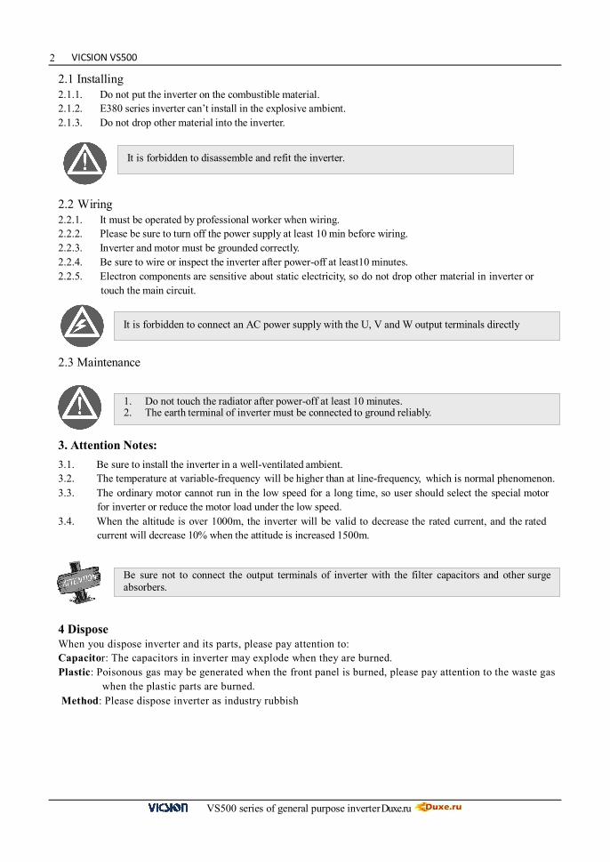
2.1 Installing 2.1.1. Do not put the inverter on the combustible material. 2.1.2. E380 series inverter can’t install in the explosive ambient. 2.1.3. Do not drop other material into the inverter. 2.2 Wiring 2.2.1. It must be operated by professional worker when wiring. 2.2.2. Please be sure to turn off the power supply at least 10 min before wiring. 2.2.3. Inverter and motor must be grounded correctly. 2.2.4. Be sure to wire or inspect the inverter after power-off at least10 minutes. 2.2.5. Electron components are sensitive about static electricity, so do not drop other material in inverter or
touch the main circuit.
2.3 Maintenance
3. Attention Notes:
3.1. Be sure to install the inverter in a well-ventilated ambient. 3.2. The temperature at variable-frequency will be higher than at line-frequency, which is normal phenomenon. 3.3. The ordinary motor cannot run in the low speed for a long time, so user should select the special motor
for inverter or reduce the motor load under the low speed. 3.4. When the altitude is over 1000m, the inverter will be valid to decrease the rated current, and the rated
current will decrease 10% when the attitude is increased 1500m.
4 Dispose When you dispose inverter and its parts, please pay attention to: Capacitor: The capacitors in inverter may explode when they are burned. Plastic: Poisonous gas may be generated when the front panel is burned, please pay attention to the waste gas
when the plastic parts are burned. Method: Please dispose inverter as industry rubbish
It is forbidden to connect an AC power supply with the U, V and W output terminals directly
It is forbidden to disassemble and refit the inverter.
1. Do not touch the radiator after power-off at least 10 minutes. 2. The earth terminal of inverter must be connected to ground reliably.
Be sure not to connect the output terminals of inverter with the filter capacitors and other surge absorbers.
Duxe.ru VICSION VS500
VS500 series of general purpose inverter Duxe.ru
3
1.INTRODUCTION
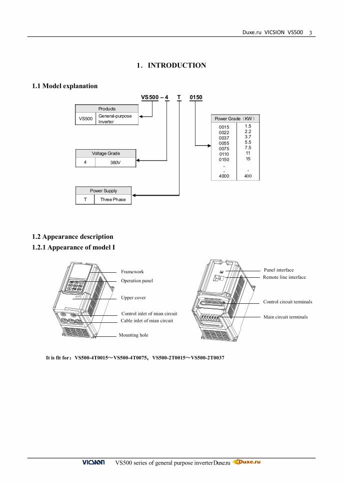
1.1 Model explanation
1.2 Appearance description 1.2.1 Appearance of model I
It is fit for:VS500-4T0015~VS500-4T0075,VS500-2T0015~VS500-2T0037
Products
VS500 General-purpose Inverter
Voltage Grade
4 380V
Power Supply
T Three Phase
Power Grade(KW)
0015 0022 0037 0055 0075 0110 0150
.
. 4000
1.5 2.2 3.7 5.5 7.5 11 15 .
400
VS500 – 4 T 0150
Framework Operation panel Upper cover Control inlet of mian circuit Cable inlet of mian circuit
Mounting hole
Panel interface Remote line interface
Control circuit terminals
Main circuit terminals
VICSION VS500
VS500 series of general purpose inverter Duxe.ru
4
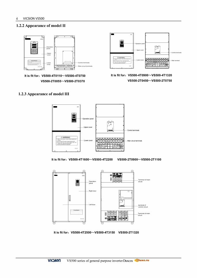
1.2.2 Appearance of model II
1.2.3 Appearance of model III
VS500
Operation panel
Main circuit terminals
Control terminals
Lower cover
Upper cover
R S TPOWER µ çÔ ´
UMOTOR µ ç» úP (+) (-) V W
operation.
at least 10min. after disconnecting power.
1.Refer to the instruction manual before installation and
3.Do not remove any cover while applying power and
4.Securely ground(earth) the equipment.
2.Do not connect AC power to output terminals UVW.
! WARNING
VS500
! WARNING and operation.2.Do not connect AC power to output terminals UVW.
4.Securely ground(earth) the equipment .
3.Do not remove any cover while applying power
1.Refer to the instruction manual before i nstal lation
and at least 10min. af ter disconnecting power.
Operation panel
V
<<
FWD
STOP
AH z
JOG
R UN
ESC
DOWN
REVSET
UP
Right door
Left door terminal ofcontrol circuit
Terminal of maincircuit
Terminal of maincircuit
It is fit for:VS500-4T1600~VS500-4T2200 VS500-2T0900~VS500-2T1100
It is fit for:VS500-4T2500~VS500-4T3150 VS500-2T1320
It is fit for:VS500-4T0110~VS500-4T0750 VS500-2T0055~VS500-2T0370
It is fit for:VS500-4T0900~VS500-4T1320
VS500-2T0450~VS500-2T0750
VS5 00
Control terminals
Lower cover
Upper cover
R S T源电POWER
U机电MOTOR P (+) (-) V W
operation.
at least 10min. after disconnecting power.
1.Refer to the instruction manual before installation and
3.Do not remove any cover while applying power and
4.Securely ground(earth) the equipment.
2.Do not connect AC power to output terminals UVW.
! WARNING
Main terminal
Operation panel
V S50 0
Main circuit terminals
Contro l terminals and o perat ion.
and at least 10m in. af ter d isconnect ing power.
1.Refer to the i nst ruction m anual before i nstallat ion
3.Do not rem ove any cover while ap plyi ng power
4.S ecurely ground(earth) the equipm ent.
2.Do not connect AC power to output term inals UV W.
! W ARNING
Lower cover
Upper cover
Operation panel
Duxe.ru VICSION VS500
VS500 series of general purpose inverter Duxe.ru
5
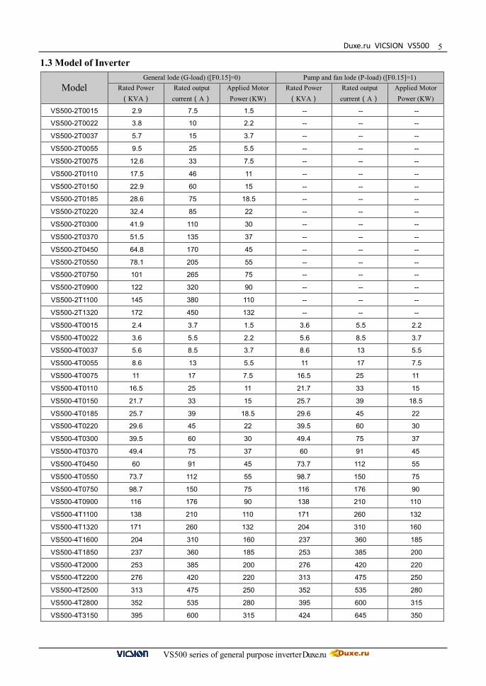
1.3 Model of Inverter
Model General lode (G-load) ([F0.15]=0) Pump and fan lode (P-load) ([F0.15]=1)
Rated Power (KVA)
Rated output current(A)
Applied Motor Power (KW)
Rated Power (KVA)
Rated output current(A)
Applied Motor Power (KW)
VS500-2T0015 2.9 7.5 1.5 -- -- --
VS500-2T0022 3.8 10 2.2 -- -- --
VS500-2T0037 5.7 15 3.7 -- -- --
VS500-2T0055 9.5 25 5.5 -- -- --
VS500-2T0075 12.6 33 7.5 -- -- --
VS500-2T0110 17.5 46 11 -- -- --
VS500-2T0150 22.9 60 15 -- -- --
VS500-2T0185 28.6 75 18.5 -- -- --
VS500-2T0220 32.4 85 22 -- -- --
VS500-2T0300 41.9 110 30 -- -- --
VS500-2T0370 51.5 135 37 -- -- --
VS500-2T0450 64.8 170 45 -- -- --
VS500-2T0550 78.1 205 55 -- -- --
VS500-2T0750 101 265 75 -- -- --
VS500-2T0900 122 320 90 -- -- --
VS500-2T1100 145 380 110 -- -- --
VS500-2T1320 172 450 132 -- -- --
VS500-4T0015 2.4 3.7 1.5 3.6 5.5 2.2
VS500-4T0022 3.6 5.5 2.2 5.6 8.5 3.7
VS500-4T0037 5.6 8.5 3.7 8.6 13 5.5
VS500-4T0055 8.6 13 5.5 11 17 7.5
VS500-4T0075 11 17 7.5 16.5 25 11
VS500-4T0110 16.5 25 11 21.7 33 15
VS500-4T0150 21.7 33 15 25.7 39 18.5
VS500-4T0185 25.7 39 18.5 29.6 45 22
VS500-4T0220 29.6 45 22 39.5 60 30
VS500-4T0300 39.5 60 30 49.4 75 37
VS500-4T0370 49.4 75 37 60 91 45
VS500-4T0450 60 91 45 73.7 112 55
VS500-4T0550 73.7 112 55 98.7 150 75
VS500-4T0750 98.7 150 75 116 176 90
VS500-4T0900 116 176 90 138 210 110
VS500-4T1100 138 210 110 171 260 132
VS500-4T1320 171 260 132 204 310 160
VS500-4T1600 204 310 160 237 360 185
VS500-4T1850 237 360 185 253 385 200
VS500-4T2000 253 385 200 276 420 220
VS500-4T2200 276 420 220 313 475 250
VS500-4T2500 313 475 250 352 535 280
VS500-4T2800 352 535 280 395 600 315
VS500-4T3150 395 600 315 424 645 350

VICSION VS500
VS500 series of general purpose inverter Duxe.ru
6
1.4 Specifications
Input Rated voltage and freq.
Three-voltage(4T****)
380V 50/60Hz Three-voltage(2T****)
220V 50/60Hz Single-voltage(2S****)
220V 50/60Hz
Permissible voltage fluctuation
Three-voltage(4T****) 300V~460V
Three-voltage(4T****) 170V~270V
Three-voltage(4T****) 170V~270V
Output
Voltage Three-voltage:0~380 V Single-voltage:0~220 V
Frequency 0 Hz ~400Hz
Over-loading Endurance
110% rated current for long-term;150% rated current for 1min;180% rated current for 2s
Control System VVVF control
Control Characteristics
Freq. Control Resolution
Analog Input 0.1% of maximum output freq
Digital Input 0.01Hz
External pulse 0.1% of maximum freq.
Freq.
Precision
Analog Input Within 0.2% of maximum output freq.
Digital Input Within 0.01% of setting freq.
External pulse 0.1% of maximum freq.
V/F Curve (Voltage-Frequency
characteristics)
Reference freq. can be discretional set between 5 and 400Hz. And V/F curve with multimode can be discretional set. There are also three curves provided, constant torque curve, Dec torque curve 1 and Dec torque curve 2.
Control Characteristics
Torque boost Manual torque boost can be set between 0 and 20 percent; Automatic torque boost can be set according to output current.
Automatic current/voltage Limiting
It will determine automatically the current and voltage of stator of motor, which will be controlled within the allowable range.
Under voltage inhibit feature In running
It is especial for the users with lower-power supply and voltage fluctuate frequently, even the voltage is lower than Permissible voltage, and the system will maintain the longest running time.
Typical Functions
Multi-speed selection And Wobble freq. running
Up to 8 stages of programmable multi-speed control, 6 kinds of running mode and 15 stages ofmulti-speed. Wobble freq. function is composed of preset freq., center freq. adjusted and save state and restart when inverter just had power off
Embedded PID control Optional inner bipolar PID controller, 5-pump voltage regulation control system (supply water or gas), with sleep/ wake up, a typical energy-saving function.
RS485 communication and synchronization control
Through RS485 communication, master inverter is the role of synchronous controller linkage controlling proportion presupposition and trimming, slave inverter running frequency superposition and trimming internal. In system of multi-gearing series use, have load self-equalized function, all gearing load proportion according to pre-set to keep consistent strictly.
Dedicated functions of drawing machine
Possessing coil diameter calculation, fast high-precision PID control with feed forwardcompensation, disconnection protection and stop at fixed length, etc., being able to realize stable winding operation under various states.
Droop control Realizing power equalization of multiple inverters with the same drive chain, and being able to realize control characteristics of the torque motor through appropriately setting parameters.
Freq Setting
Analog input DC voltage 0~5V、0~10V,DC current 0~20mA Pulse input Its amplitude value is between 5 and 30V、and its freq. is within 50KHz
Digital input It can set by operation panel,RS485,UP/DW terminal,also can set multiple
combinations with analogue input
Output Signal OC output Two OC output, As many as 16 species of choice, fault relay output similarly optional.
Analog output Two 0~10V voltage or 0~20 mA current signal, Upper and lower limits can be set separately

Duxe.ru VICSION VS500
VS500 series of general purpose inverter Duxe.ru
7
Typical Functions
Automatic energy saving running
The output current timely adjust output voltage and slip compensation, the motor has been working at the highest efficiency. According to the status of the scene automatic energy saving operation can set the depth. In particular, it suitable for ball-mill and other energy-saving field of micro-adjustment frequency.
Voltage stabilizing running Automatically
Three ways for selection: Dynamic voltage regulation、Static Voltage regulation、 No Voltage regulation, to get the most stable operating result
Acceleration/deceleration Time setting 0.1Sec~6000min Continuous set, S type 、linear mode for selection Determine speed and restart
To achieve Smoothing restart and instantaneous-stop restart function of running motor.
Counter、Timer
Embedded one timer and one counter, which will help the system’s integration.
Operation functions Upper and Lower frequency setting,frequency skip operation,Reversal operating restriction,Slip frequency compensation,automatic stable voltage operation, RS485 communication,frequency increasing/decreasing control, fault recovery operation.
Display Operation panel display
Running status
Output Freq.,Output current,Output voltage,Motor rotate speed,Setting Freq., Model temperature,PID setting,PID feedback,Analog I/O
Alarm content Last running parameters record: Last six fault record,Output frequency of last fault trip、Setting frequency、Output current、Output voltage、DC voltage、Model Temperature
Protection / Warning functions Over current,over voltage, under current, under voltage,electronic thermal, overheating, extreme high temperature,short circuit, Phase-lacking of output, internal memory fault
Environmental
Conditions
Ambient temperature -10ºC 至+50ºC
Ambient humidity Under 90%(non-condensing) Ambient environment Indoors(no inflammable gasses or dust) Altitude Lower than 1000m
Configuration Enclosure rating IP20
Cooling method Fans cooling Installation Hanging
VICSION VS500
VS500 series of general purpose inverter Duxe.ru
8
2. INSTALLATION GUIDELINES
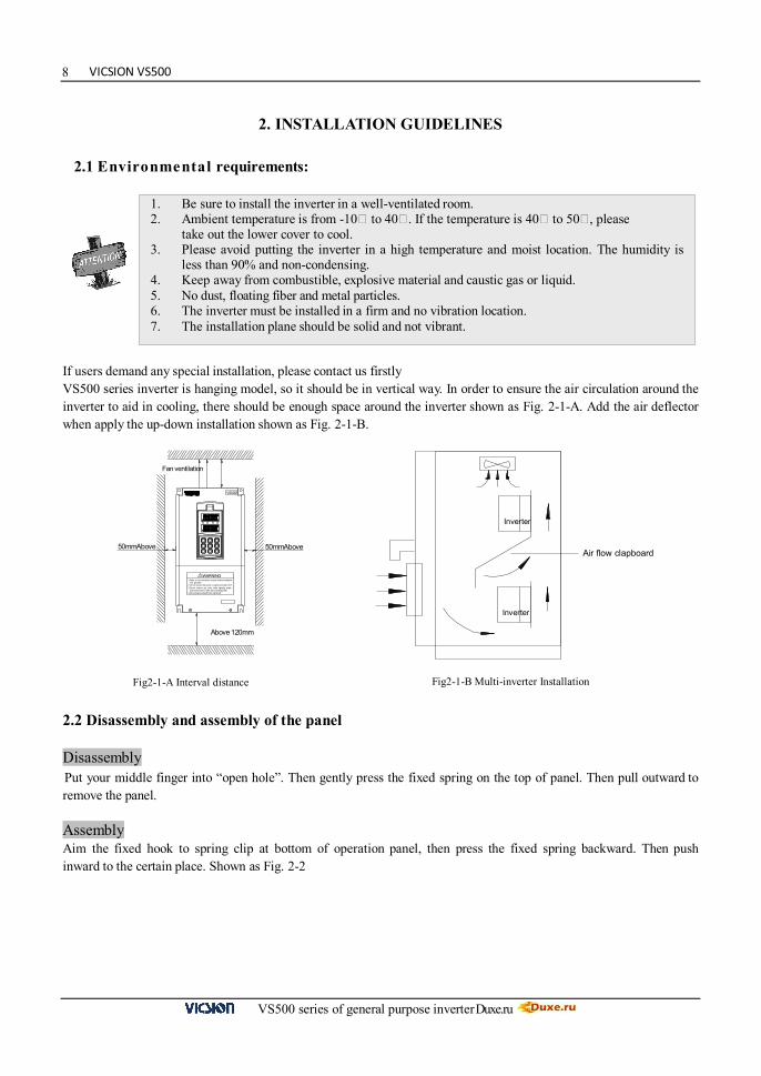
2.1 Environmental requirements: If users demand any special installation, please contact us firstly VS500 series inverter is hanging model, so it should be in vertical way. In order to ensure the air circulation around the inverter to aid in cooling, there should be enough space around the inverter shown as Fig. 2-1-A. Add the air deflector when apply the up-down installation shown as Fig. 2-1-B.
Fig2-1-A Interval distance Fig2-1-B Multi-inverter Installation
2.2 Disassembly and assembly of the panel Disassembly Put your middle finger into “open hole”. Then gently press the fixed spring on the top of panel. Then pull outward to remove the panel. Assembly Aim the fixed hook to spring clip at bottom of operation panel, then press the fixed spring backward. Then push inward to the certain place. Shown as Fig. 2-2
Inverter
Inverter
Air flow clapboard
VS500
Above 120mm
Fan ventilation
WARNING!
2.Do not connect AC power to output terminals UVW.
4.Securely ground(earth) the equipment.
3.Do not remove any cover whi le applying power
1.Refer to the instruction manual before installati on
and at least 10min. after disconnecting power.
and operation.
50mmAbove 50mmAbove
1. Be sure to install the inverter in a well-ventilated room. 2. Ambient temperature is from -10 to 40 . If the temperature is 40 to 50 , please
take out the lower cover to cool. 3. Please avoid putting the inverter in a high temperature and moist location. The humidity is
less than 90% and non-condensing. 4. Keep away from combustible, explosive material and caustic gas or liquid. 5. No dust, floating fiber and metal particles. 6. The inverter must be installed in a firm and no vibration location. 7. The installation plane should be solid and not vibrant.

Duxe.ru VICSION VS500
VS500 series of general purpose inverter Duxe.ru
9
Panel base
Spring cilp
2.3 Disassembly and assembly of the cover board 2.3.1 Disassembly and assembly of plastic cover board
It is fit for:VS500-4T0015~VS500-4T0075,VS500-2T0015~VS500-2T0037
Disassembly Put the finger into the “portable hole”, pull upward to move the cover form the shell, then pull downward, which will remove the cover board.
Assembly Lift the bottom of cover up to about 15℃, inserting the “Fixed hook” into the hold down groove, then press the cover down to hear a sound of “Click”, which means the cover board has already been mounted and shown as Fig. 2-3-A.
Fig2-3-A Disassembly and assembly of plastic cover board
2.3.2 Disassembly and assembly of lower cover board
It is fit for:VS500-4T0110~VS500-4T1100,VS500-2T0055~VS500-2T0550
Disassembly 1. Take two screws at bottom of lower cover board. 2. Move the lower cover board downward.
Assembly 1. Put the lower cover board parallel with the interval.
2. Move the lower cover board upward.
3. Screw the bottom of lower cover board.
Fig.2-2 Disassembly and assembly of the panel
Portable hole
Fixed hook
Hole
VICSION VS500
VS500 series of general purpose inverter Duxe.ru
10
VS500
D
H H1
and operation.
and at least 10min. after disconnecting power.
1.Refer to the instruction manual before instal lation
3.Do not remove any cover while app lying power
4.Secure ly ground(earth) the equipment.
2.Do not connect AC power to output terminals UVW.
! WARNING
W1
VS500
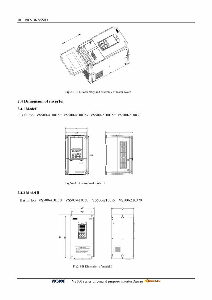
Fig.2-3--B Disassembly and assembly of lower cover
2.4 Dimension of inverter
2.4.1 Model It is fit for:VS500-4T0015~VS500-4T0075,VS500-2T0015~VS500-2T0037
Fig2-4-A Dimension of model Ⅰ
2.4.2 ModelⅡ
It is fit for:VS500-4T0110~VS500-4T0750,VS500-2T0055~VS500-2T0370
Fig2-4-B Dimension of modelⅡ
HH1
W1
W
D
Duxe.ru VICSION VS500
VS500 series of general purpose inverter Duxe.ru
11
WARNING!
2.Do not connect AC power to output terminals UVW.
4.Securely ground(earth) the equipment.
3.Do not remove any cover while applying power and
1.Refer to the instruction manual before installation and
at leas t 10min. after disconnecting power.
operation.
D
H H1
WW1
V S500
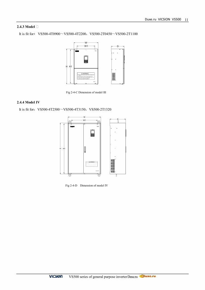
2.4.3 Model
It is fit for:VS500-4T0900~VS500-4T2200,VS500-2T0450~VS500-2T1100
Fig 2-4-C Dimension of model III 2.4.4 Model IV
It is fit for:VS500-4T2500~VS500-4T3150,VS500-2T1320
Fig 2-4-D Dimension of model IV
D
H H1
WW1
VS50 0
! WARNING and operat ion.2.Do not connect A C power to output terminals UVW.
4.Securel y ground(earth) the equipment.
3.Do not rem ove any cover while apply ing power
1.Refer to the instruct ion manual before installation
and at least 10min. after disconnect ing power.
VICSION VS500
VS500 series of general purpose inverter Duxe.ru
12
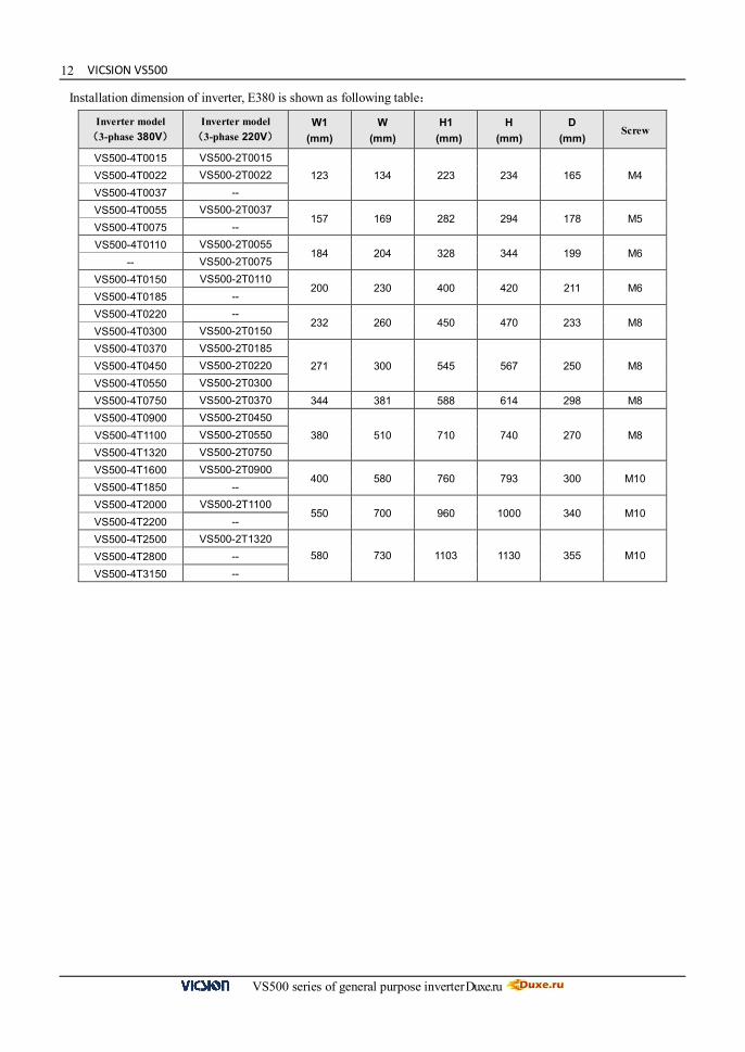
Installation dimension of inverter, E380 is shown as following table:
Inverter model (3-phase 380V)
Inverter model (3-phase 220V)
W1 (mm)
W (mm)
H1 (mm)
H (mm)
D (mm)
Screw
VS500-4T0015 VS500-2T0015 123 134 223 234 165 M4 VS500-4T0022 VS500-2T0022
VS500-4T0037 -- VS500-4T0055 VS500-2T0037
157 169 282 294 178 M5 VS500-4T0075 -- VS500-4T0110 VS500-2T0055
184 204 328 344 199 M6 -- VS500-2T0075
VS500-4T0150 VS500-2T0110 200 230 400 420 211 M6
VS500-4T0185 -- VS500-4T0220 --
232 260 450 470 233 M8 VS500-4T0300 VS500-2T0150 VS500-4T0370 VS500-2T0185
271 300 545 567 250 M8 VS500-4T0450 VS500-2T0220 VS500-4T0550 VS500-2T0300 VS500-4T0750 VS500-2T0370 344 381 588 614 298 M8 VS500-4T0900 VS500-2T0450
380 510 710 740 270 M8 VS500-4T1100 VS500-2T0550 VS500-4T1320 VS500-2T0750 VS500-4T1600 VS500-2T0900
400 580 760 793 300 M10 VS500-4T1850 -- VS500-4T2000 VS500-2T1100
550 700 960 1000 340 M10 VS500-4T2200 -- VS500-4T2500 VS500-2T1320
580 730 1103 1130 355 M10 VS500-4T2800 -- VS500-4T3150 --
Duxe.ru VICSION VS500
VS500 series of general purpose inverter Duxe.ru
13
Inverter U
V
W M
Motor
RC absorb
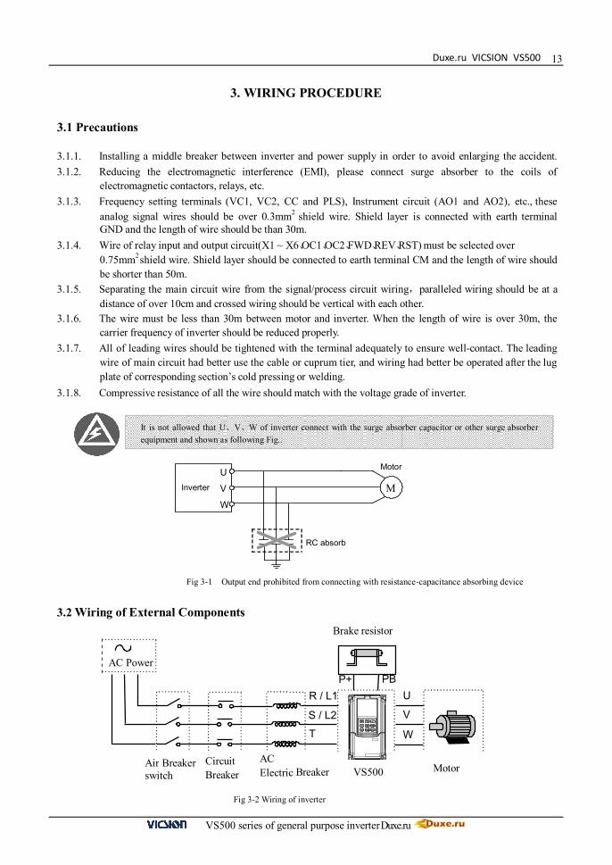
3. WIRING PROCEDURE
3.1 Precautions
3.1.1. Installing a middle breaker between inverter and power supply in order to avoid enlarging the accident. 3.1.2. Reducing the electromagnetic interference (EMI), please connect surge absorber to the coils of
electromagnetic contactors, relays, etc. 3.1.3. Frequency setting terminals (VC1, VC2, CC and PLS), Instrument circuit (AO1 and AO2), etc., these
analog signal wires should be over 0.3mm2 shield wire. Shield layer is connected with earth terminal GND and the length of wire should be than 30m.
3.1.4. Wire of relay input and output circuit(X1 ~ X6、OC1、OC2、FWD、REV、RST) must be selected over 0.75mm2 shield wire. Shield layer should be connected to earth terminal CM and the length of wire should be shorter than 50m.
3.1.5. Separating the main circuit wire from the signal/process circuit wiring,paralleled wiring should be at a distance of over 10cm and crossed wiring should be vertical with each other.
3.1.6. The wire must be less than 30m between motor and inverter. When the length of wire is over 30m, the carrier frequency of inverter should be reduced properly.
3.1.7. All of leading wires should be tightened with the terminal adequately to ensure well-contact. The leading wire of main circuit had better use the cable or cuprum tier, and wiring had better be operated after the lug plate of corresponding section’s cold pressing or welding.
3.1.8. Compressive resistance of all the wire should match with the voltage grade of inverter.
It is not allowed that U、V、W of inverter connect with the surge absorber capacitor or other surge absorber equipment and shown as following Fig..
3.2 Wiring of External Components
Fig 3-1 Output end prohibited from connecting with resistance-capacitance absorbing device
Fig 3-2 Wiring of inverter
Brake resistor
R / L1
S / L2
T
U
V
W
AC Power P+ PB
Air Breaker switch
Circuit Breaker
AC Electric Breaker VS500 Motor

VICSION VS500
VS500 series of general purpose inverter Duxe.ru
14 Power Supply
It is according to the rated input power specifications in manual. Air-break switch
1. When the inverter is in maintenance or leave-unused, the air-break switch should isolate the inverter from power supply.
2. Input side of inverter takes place the fault of short-circuits or low-voltage, the air-break would take the protection.
Contactor Control the power-on or power-off of inverter expediently.
AC electric reactor 1. Improve the power factor. 2. Reduce the harmonic wave input for the electric network. 3. Weaken the imbalance effect on 3-phase power voltage.
Brake resistor In the situation of regenerative braking, avoiding bringing voltage too highly.
Recommending specification of commanded equipment is shown as following table:
Model Applied Motor(KW) Wire spec
(Main circuit)(mm2)
Air-break (A)
Magnetic contactor (A) G-load P-load
VS500-2T0015 1.5 -- 4 20 18
VS500-2T0022 2.2 -- 4 20 18
VS500-2T0037 3.7 -- 6 40 25
VS500-2T0055 5.5 -- 10 63 32
VS500-2T0075 7.5 -- 10 63 38
VS500-2T0110 11 -- 16 100 50
VS500-2T0150 15 -- 25 160 80
VS500-2T0185 18.5 -- 25 160 80
VS500-2T0220 22 -- 25 160 95
VS500-2T0300 30 -- 50 200 150
VS500-2T0370 37 -- 50 250 170
VS500-2T0450 45 -- 70 250 170
VS500-2T0550 55 -- 95 400 225
VS500-2T0750 75 -- 95 400 330
VS500-2T0900 90 -- 150 630 330
VS500-2T1100 110 -- 185 630 400
VS500-2T1320 132 -- 185 800 500
VS500-4T0015 1.5 2.2 2.5 16 12
VS500-4T0022 2.2 3.7 4 16 12
VS500-4T0037 3.7 5.5 4 20 18
VS500-4T0055 5.5 7.5 6 32 18
VS500-4T0075 7.5 11 6 40 25
VS500-4T0110 11 15 10 63 32
VS500-4T0150 15 18.5 10 63 38
VS500-4T0185 18.5 22 16 100 50
VS500-4T0220 22 30 16 125 50
VS500-4T0370 37 45 25 160 95

Duxe.ru VICSION VS500
VS500 series of general purpose inverter Duxe.ru
15
Model Applied Motor(KW) Wire spec
(Main circuit)(mm2)
Air-break (A)
Magnetic contactor (A) G-load P-load
VS500-4T0450 45 55 50 200 115
VS500-4T0550 55 75 50 200 150
VS500-4T0750 75 90 70 250 170
VS500-4T0900 90 110 70 315 225
VS500-4T1100 110 132 95 400 225
VS500-4T1320 132 160 95 400 330
VS500-4T1600 160 185 150 630 330
VS500-4T1850 185 200 150 630 400
VS500-4T2000 200 220 185 630 400
VS500-4T2200 220 250 185 800 500
VS500-4T2500 250 280 240 800 500
VS500-4T2800 280 315 240 1000 630
VS500-4T3150 315 350 300 1250 630
Note: When inverters of same model of VS500 series are connected with loads from fan or water pump, the adaptive motor power can be increased one power level as compared to connection with the generic loads.
3.3 Basic wiring
M
Motor
Ta
Tb
Tc
U
W V
R
S T
FWD
REV
CM
AO1
AO2 GND
Fault alarm
Voltmeter(0~10V)/ Current meter(0~20mA)
Three-phase Power supply
FWD Order
E
X1
X2 X3 X4
X5
X6
CM
RST
PLC input terminal
VS
VC1
CC
P-
PB External brake resistor
Open-circuit Collector output
OC1
OC2
CM
Earth
× × ×
Three-phase Breaker
P
24V Auxiliary DC power
0 ~ 10V Frequency set
0 ~ 5V Frequency set
VC2
GND
0 ~ 20mA Frequency set
Voltmeter(0~10V)/ Current meter(0~20mA)
PLS
CM
0 ~ 50KHz Frequency set
E
E
E
E
E
REV Order
Fault Reset
VICSION VS500
VS500 series of general purpose inverter Duxe.ru
16
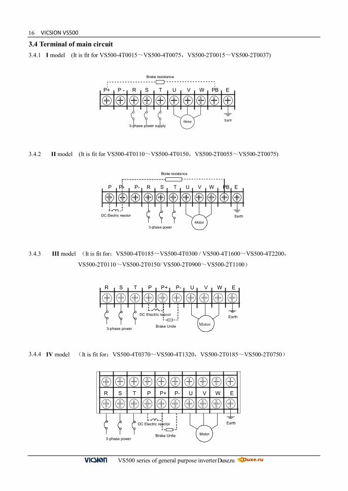
3.4 Terminal of main circuit
3.4.1 I model (It is fit for VS500-4T0015~VS500-4T0075,VS500-2T0015~VS500-2T0037)
3.4.2 II model (It is fit for VS500-4T0110~VS500-4T0150,VS500-2T0055~VS500-2T0075)
3.4.3 III model (It is fit for:VS500-4T0185~VS500-4T0300 / VS500-4T1600~VS500-4T2200,
VS500-2T0110~VS500-2T0150/ VS500-2T0900~VS500-2T1100)
3.4.4 IV model (It is fit for:VS500-4T0370~VS500-4T1320,VS500-2T0185~VS500-2T0750)
P+ P - R S T U V W PB E
Motor 3-phase power supply
Brake resistance
Earth
DC Electric reactor
Brake resistance
Motor 3-phase power
P P+ P- R S T U V W PB E
Earth
R S T P P+ P- U V W E
Motor 3-phase power
Earth
Brake Unite
DC Electric reacor
R S T P P+ P- U V W E
Motor 3-phase power
Earth
Brake Unite
DC Electric reactor
Duxe.ru VICSION VS500
VS500 series of general purpose inverter Duxe.ru
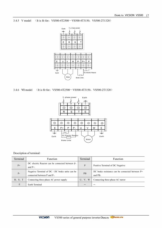
17
3.4.5 V model (It is fit for:VS500-4T2500~VS500-4T3150,VS500-2T1320) 3.4.6 VI model (It is fit for:VS500-4T2500~VS500-4T3150,VS500-2T1320) Description of terminal:
Terminal Function Terminal Function
P+ DC electric Reactor can be connected between P- and P+.
P Positive Terminal of DC Negative
P- Negative Terminal of DC / DC brake unite can be connected between P and P-.
PB DC brake resistance can be connected between P+ and PB.
R、S、T Connecting three-phase AC power supply U、V、W Connecting three-phase AC motor
E Earth Terminal -- --
E R S T
3 -p hase power Earth
E U V W P- P+ P
Brake Unite
DC Electric Reacto Earth
Motor
R S T E
Earth 3 -phase power
E P+ P P- U V W E
Brake Unite
DC Electric Reactor Earth
Motor
Earth
VICSION VS500
VS500 series of general purpose inverter Duxe.ru
18
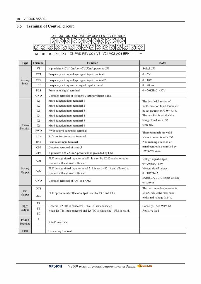
X1 X3 X5 CM RST 24V OC2 PLS CC GND AO2
+ X2 X4 FWD REV OC1 VS VC1 VC2 AO1 ERH TA TB TC - X6
3.5 Terminal of Control circuit
Type Terminal Function Notes
Analog Input
VS It provides +10V/10mA or +5V/50mA power to JP1 Switch JP1
VC1 Frequency setting voltage signal input terminal 1 0~5V
VC2 Frequency setting voltage signal input terminal 2 0~10V
CC Frequency setting current signal input terminal 0~20mA
PLS Pulse input signal terminal 0~50KHz/5~30V
GND Common terminal of Frequency setting voltage signal
Control Terminal
X1 Multi-function input terminal 1 The detailed function of multi-function Input terminal is by set parameter F3.0~F3.5, The terminal is valid while being closed with CM terminal.
X2 Multi-function input terminal 2
X3 Multi-function input terminal 3
X4 Multi-function input terminal 4
X5 Multi-function input terminal 5
X6 Multi-function input terminal 6
FWD FWD control command terminal Those terminals are valid when it connects with CM. And running direction of panel control is controlled by FWD-CM state
REV REV control command terminal
RST Fault reset input terminal
CM Common terminal of control
24V It provides +24V/50mA power and is grounded by CM.
Analog Output
AO1 PLC voltage signal input terminal1. It is set by F2.13 and allowed to connect with external voltmeter.
voltage signal output : 0~20mA/0~15V. Voltage signal output : 0~10V/1mA Switch JP2、JP3 select voltage or current
AO2 PLC voltage signal input terminal 2. It is set by F2.14 and allowed to connect with external voltmeter.
GND Common terminal of AM1and AM2
OC Output
OC1 PLC open-circuit collector output is set by F3.6 and F3.7
The maximum load-current is 50mA, while the maximum withstand voltage is 24V. OC2
PLC output
TA General , TA-TB is connected,TA-Tc is unconnected when TA-TB is unconnected and TA-TC is connected,F3.8 is valid.
Capacity:AC 250V 1A Resistive load
TB
TC
RS485 Interface
+ RS485 interface
-
ERH Grounding terminal

Duxe.ru VICSION VS500
VS500 series of general purpose inverter Duxe.ru
19
Explanation about JP:
JP1: 1-2shorted:Input +5V/50mA signal 2-3shorted:Input +10V/10mA signal JP2: 1-2 shorted:AO1input voltage signal 2-3 shorted:AO1 input current signal JP3: 1-2 shorted:AO2 input voltage signal
2-3 shorted:AO2 input current signal
+5V
+10V
JP1 JP2
VO2
VO1
JP3
CO
1
CO
2

VICSION VS500
VS500 series of general purpose inverter Duxe.ru
20
<<
RUN Hz A V
ESC JOG
SET REV FWD
STOP
Mode indicate light
Main LED
Auxiliary LED
Set
IncreasingDecreasing
Return SwitchJogFWDREVStop
UnitRUN
Hz A
VMode indicate light
Main LED
Return
Set
IncreasingDecreasing
Unit
Potentiometer
SwitchFED
REV
Stop
4. OPERATIONS OF INVERTER AND SIMPLE RUNNING
Operation panel has two functions:One is to modify the running state parameters. The other is to check and modify the internal parameters. So operation panel has two modes: modify mode, check and modify parameters mode. Usually, operation panel mode is in normal modify mode when inverter is just power-on. At this time, current running parameter , which is shown on operation panel , is controlled by F6.12、F6.13. The operation panel mode will return the normal modify mode, if there isn’t any operation on panel in 1 min. 4.1 Operation panel 4.1.1 Panel layout
4.1.2 Function of Key Item Function
Display
Main LED It displays current state and setting parameter.
Auxiliary LED
It displays current state and setting parameter. At the beginning of power supply, it displays inverter’s program version, and it will return normality in 2 second. Small panel layout doesn’t have this auxi liary LED
A、Hz、V The corresponding unit of current display.
RUN Operation indicator light. The inverter is running and U, V and W output voltage.
Keypad
FWD key:When F0.1 is 0 and press this key, the inverter will running forward to setting frequency according to appointed ACC or DEC curve.
REV key: When F0.1 is 1 and press this key, the inverter will be running backward to setting frequency according to appointed ACC or DEC curve.
Stop and Reset key: When F0.4 is 000#, STOP is valid for panel control. If F0.4 is 001#, STOP is valid for all kinds of control methods. If inverter occur fault, press this key to reset it and return stop mode. If stop key is used together with copy and read-in of internal parameters will be done
Fig.4-1-A Panel layout Fig.4-1-B Small Panel layout
Duxe.ru VICSION VS500
VS500 series of general purpose inverter Duxe.ru
21
Keypad
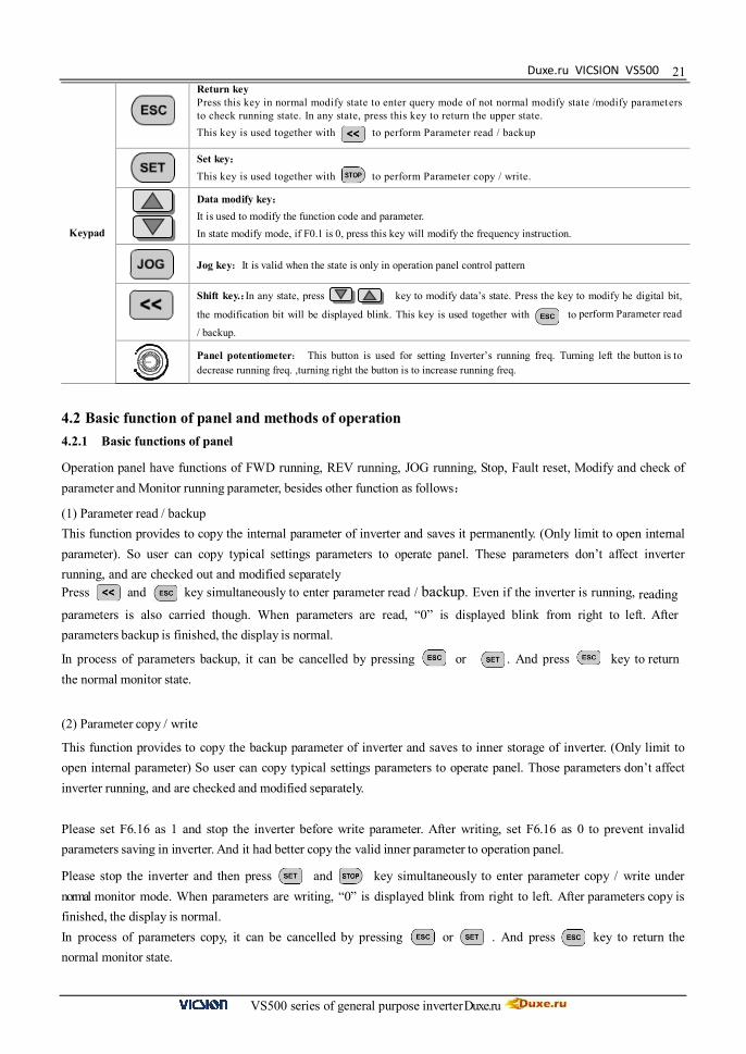
Return key Press this key in normal modify state to enter query mode of not normal modify state /modify parameters to check running state. In any state, press this key to return the upper state. This key is used together with to perform Parameter read / backup
Set key: This key is used together with to perform Parameter copy / write.
Data modify key: It is used to modify the function code and parameter. In state modify mode, if F0.1 is 0, press this key will modify the frequency instruction.
Jog key:It is valid when the state is only in operation panel control pattern
Shift key. :In any state, press key to modify data’s state. Press the key to modify he digital bit,
the modification bit will be displayed blink. This key is used together with to perform Parameter read
/ backup. Panel potentiometer: This button is used for setting Inverter’s running freq. Turning left the button is to
decrease running freq. ,turning right the button is to increase running freq.
4.2 Basic function of panel and methods of operation 4.2.1 Basic functions of panel
Operation panel have functions of FWD running, REV running, JOG running, Stop, Fault reset, Modify and check of parameter and Monitor running parameter, besides other function as follows:
(1) Parameter read / backup This function provides to copy the internal parameter of inverter and saves it permanently. (Only limit to open internal parameter). So user can copy typical settings parameters to operate panel. These parameters don’t affect inverter running, and are checked out and modified separately Press and key simultaneously to enter parameter read / backup. Even if the inverter is running, reading parameters is also carried though. When parameters are read, “0” is displayed blink from right to left. After parameters backup is finished, the display is normal.
In process of parameters backup, it can be cancelled by pressing or . And press key to return the normal monitor state.
(2) Parameter copy / write
This function provides to copy the backup parameter of inverter and saves to inner storage of inverter. (Only limit to open internal parameter) So user can copy typical settings parameters to operate panel. Those parameters don’t affect inverter running, and are checked and modified separately.
Please set F6.16 as 1 and stop the inverter before write parameter. After writing, set F6.16 as 0 to prevent invalid parameters saving in inverter. And it had better copy the valid inner parameter to operation panel.
Please stop the inverter and then press and key simultaneously to enter parameter copy / write under normal monitor mode. When parameters are writing, “0” is displayed blink from right to left. After parameters copy is finished, the display is normal. In process of parameters copy, it can be cancelled by pressing or . And press key to return the normal monitor state.

VICSION VS500
VS500 series of general purpose inverter Duxe.ru
22
(3) Modify and check the internal parameter Press key to enter Modify and check internal parameter mode under normal mode with general ways to check and modify data.
4) Modify and check the backup parameter
Under normal monitor mode, press and key simultaneously to enter modify and check the backup parameter mode. When panel displays function code, “F” in the fourth place of main LED will be displayed blink, which means current modify and check parameters is backup parameter.
4.2.2 Methods of panel operation (1) State parameter inquiry (eg.)
Main display: 45.00 Output freq
Normal Monitor
State Auxiliary display: 2.3 Output current
Main display: d-0 Monitor code
State Parameter Auxiliary display: 45.00 Output freq
Main display: d-5 Function code State Parameter
Inquiry Auxiliary display: 2.3 Output current
Main display: 383 Input voltage Parameter
Inquiry Auxiliary display: 2.3 Output current
Main display: F0.0 Function code Parameter Edit
Auxiliary display: 0 Parameter data
+
Select queried status parameters
Enter parameters Modification mode Refer to next chapter
+
Return

Duxe.ru VICSION VS500
VS500 series of general purpose inverter Duxe.ru
23(2) Parameter inquiry and modify (eg.)
Normal Monitor State
Main display: 45.00 Output freq
Auxiliary display: 2.3 Output current
Parameter
Inquiry
Main display: F0.0 Function code
Auxiliary display: 0 Parameter data
Parameter Inquiry Main display: F0.2 Function code
Auxiliary display: 45.00 Parameter data
Parameter Inquiry Main display: 45.00 Parameter data
Auxiliary display: 2.3 Output current
Parameter
Modify
Main display: 50.00 Parameter data
Auxiliary display: 2.3 Output current
Parameter Storage Main display: F0.2 Function code
Auxiliary display: 50.00 Parameter data
+
+
+
Notes: The function code “F”
flushes when modifying backup parameters
Modify backup parameter
Modify parameters according to the needs
Memorize parameters
modified
Give up Modify
Continue Modify Or Return
VICSION VS500
VS500 series of general purpose inverter Duxe.ru
24
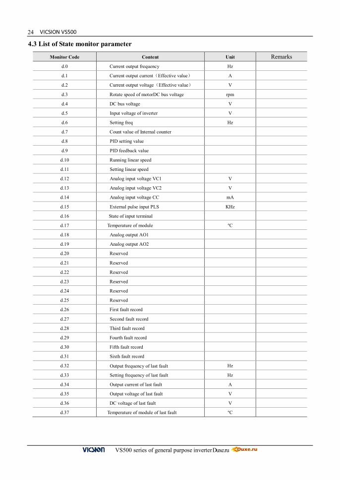
4.3 List of State monitor parameter
Monitor Code Content Unit Remarks
d.0 Current output frequency Hz
d.1 Current output current(Effective value) A d.2 Current output voltage(Effective value) V d.3 Rotate speed of motor DC bus voltage rpm d.4 DC bus voltage V d.5 Input voltage of inverter V d.6 Setting freq Hz d.7 Count value of Internal counter d.8 PID setting value d.9 PID feedback value
d.10 Running linear speed d.11 Setting linear speed d.12 Analog input voltage VC1 V d.13 Analog input voltage VC2 V d.14 Analog input voltage CC mA d.15 External pulse input PLS KHz d.16 State of input terminal
d.17 Temperature of module ºC d.18 Analog output AO1 d.19 Analog output AO2 d.20 Reserved d.21 Reserved d.22 Reserved d.23 Reserved d.24 Reserved d.25 Reserved d.26 First fault record d.27 Second fault record d.28 Third fault record d.29 Fourth fault record d.30 Fifth fault record d.31 Sixth fault record d.32 Output frequency of last fault Hz d.33 Setting frequency of last fault Hz d.34 Output current of last fault A d.35 Output voltage of last fault V d.36 DC voltage of last fault V d.37 Temperature of module of last fault ºC

Duxe.ru VICSION VS500
VS500 series of general purpose inverter Duxe.ru
25
4.4 Simple Operation
4.4.1. Initialization (1)Frequency input channel / mode selection([F0.1]) Initialization of inverter is different according to different model. If [F0.0] is 0, the frequency of inverter is set by keypad. (2) Operation channel selection([F0.4]) Initialization of inverter is different according to different model. If F0.4 is 00#0, Start and stop of inverter is controlled by and key. 4.4.2. Simply operation
Please① wire as the Fig 4-1.
②Be sure that the wiring is correct and turn the power on, the inverter will display “P.oFF” and”0”.
Auxiliary LED displays the program version transitorily.
Be③ sure that F0.1 is 0.
Please④ set parameters [F1.3] and [F1.4], according to the nameplate parameters of applied motor.
Please⑤ press key to start inverter, then the inverter will display 0.0Hz.
Please⑥ press key to increase input frequency and motor will run.
Observe⑦ the motor whether it runs normally or not. If abnormal, please stop running at once and turn off the power,
and find out the reason, then restart.
Press⑧ the key to decrease the setting frequency.
Press⑨ the key to stop running. Then turn power supply off.
M
Motor U
W V
R S T
Power supply
× × ×
Three-phase Breaker
Earth
E
Fig.4-1 simply running
It is forbidden to connect Three-phase power to output terminal U, V and W directly.
Carrier wave frequency is fixed value between 1.5 and 10 KHz. If motor does not take any load, it will a slight oscillate. So please decrease setting value of F0.16, Or setting Oscillatory inhibiting factor value of FC.11

VICSION VS500
VS500 series of general purpose inverter Duxe.ru
26
5. PARAMETERS LIST
Function Code Name Setting range Minimum Setting
Manufacture Setting
Modify Limit
F0. 0 Running mode selection
LED bits : Running mode 0:General mode 1:Special for drawing machine LED tens: Reserved LED hundreds: Reserved LED thousands: Reserved
1 0000 ★
F0. 1 Frequency input channel
/ mode selection
0:Frequency setting by operation panel
1:UP/DW Acc and Dec control
2:RS485 interface
3:Panel potentiometer
4:External voltage signal VC1(0V~5V)
5:External voltage signal VC2(0V~10V)
6:External current signal CC(0~20mA)
7:External pulse signal(0.0~50.0KHz)
8:Combination setting
9:External terminals
1 0
F0. 2 Frequency digital setting
0.00~ the upper limit frequency 0.01 0
F0. 3 Auxiliary control of freq. Digital setting
The first part of LED(form right to left): 0:Setting freq. will save after power down 1:Setting freq. will not save after power down The second part of LED: 0:Setting freq. is to keep when stopping
1:Setting freq. will save in F0.2 when stopping
2:Setting freq. is clear when stopping The third and fourth part of LED(form right to left):Reserved
1 0000
F0. 4 Operation channel selection
The first part of LED (form right to left): 0:Panel control 1:External terminals control
2:RS485 interface
The second part of LED:Function of key STOP
0:It is valid for panel control.
1:It is valid for all kinds of control method. The third and fourth part of LED(form right to left):Reserved
1 0000
F0.5 Combination methods of instruction terminals
0:Two-line mode 1 1:Two-line mode 2
2:Three-line mode 1 0 ★
Bas
ic o
pera
tion
para
met
er u
nit
Description of symbol on the function parameter list:“★” means that this parameter cannot be change during
operation;“▲” means that this parameter is related to the inverter’s model;“◆”Indicate that parameter is a random
value

Duxe.ru VICSION VS500
VS500 series of general purpose inverter Duxe.ru
27
Function Code Name Setting range Minimum Setting
Manufacture Setting
Modify Limit
F0.6
Running direction control and setting of operation instruction auxiliary
The first part of LED (form right to left): 0:Running direction is consistent with setting direction 1:Running direction is in contradiction to setting direction The second part of LED:
0:Prevention REV is valid
1:Prevention REV is invalid The third and fourth part of LED(form right to left): External operation channel auxiliary function 0:self-starting is forbidden when inverter is just power-on 1:self-starting is allowed when inverter is just power-on The fourth part of LED(form right to left): Reserved
1 0100
F0.7 The lower limit frequency 0.0~[F0.8] 0.01 0.0
F0.8 The upper limit frequency [F0.7]~400.00 Hz 0.01 50.00Hz
F0.9 Reserved
F0. 10 Acc time 1 0.1~6000 Sec 0.1 ▲
F0. 11 Dec time 1 0.1~6000 Sec 0.1 ▲
F0. 12 Characteristics parameter of Acc and Dec
The first part of LED (form right to left): 0:Beeline 1:S curve
The second part of LED:
0:Output freq. will be modified according to Acc/Dec time. 1:Output freq. will be automatically modified according to lode. The third part of LED:Unit of Acc/Dec time
0:Sec 1:Min
The fourth part of LED:Reserved
1 0000
F0. 13 Acc/Dec initial section proportion Of S curve
10.0~50.0 (%) 0.1 20.0% ★
F0. 14
Acc/Dec ascending/decline section proportion of S curve
10.0~80.0 (%) 0.1 60.0% ★
F0. 15 Lode pattern selection 0: General-purpose lode.
1: Fan and pump lode. 1 0 ★
F0. 16 Carrier wave frequency 1.5~12.0 KHz 0.1 ▲
Bas
ic o
pera
tion
para
met
er u
nit

VICSION VS500
VS500 series of general purpose inverter Duxe.ru
28
F0. 17 Carrier wave characteristics
The first part of LED (form right to left): Reserved The second part of LED:
0:Load carrier wave adjustment is invalid
1:Load carrier wave adjustment is valid
The third part of LED:
0:Heat carrier wave adjustment is invalid
1:Heat carrier wave adjustment is valid
The fourth part of LED:
0:Freq. relating carrier wave adjustment is Invalid 1:Freq. relating carrier wave adjustment is valid
1 1110
Function Code Name Setting range Minimum Setting
Manufacture Setting
Modify Limit
F0. 18 Parameter write-protection
1:Forbid to modify all parameter, except F0.2 and F0.18 2:Forbid to modify all parameter, except F0.18 Other values: all parameters are allowed to modify
1 0
F1. 0 Type of V/F Curve
0:Constant torque curve
1:Low-freq. torque curve 1
2:Low-freq. torque curve 2
3:V/F user-defined curve
1 0 ★
F1. 1 Torque Boost 0.0~20.0(%) 0.1 ▲
F1. 2 Torque boost pattern 0:Manual 1:Automatic 1 0 ★
F1. 3 Basic running frequency 5.00~the upper limit frequency 0.01 50.00
F1. 4 Max output voltage 200~500V /100~250V 1 400 220
F1. 5 V/F freq. 3 [F1.7]~[F1.3] 0.01 0.0 ★
F1. 6 V/F voltage 3 [F1.8]~100.0(%) 0.1 0.0 ★
F1. 7 V/F freq. 3 [F1.9]~[F1.5] 0.01 0.0 ★ F1. 8 V/F voltage 2 [F1.10]~[F1.6] 0.1 0.0 ★ F1. 9 V/F freq. 1 0.0~[F1.7] 0.01 0.0 ★
F1. 10 V/F voltage 1 [F1.1]~[F1.8] 0.1 0.0 ★
F1. 11 DC braking current when starting 0.0~100.0(%) 0.1 50.0
F1. 12 DC braking time when starting 0.0~20.0Sec 0.1 0 ★
F1.13 Compensation for slipping freq. 0~150(%) 1 0
F1.14 Droop control 0~100(%) 1 0
F1.15 Initial level of droop control 0~150(%) 1 25
F1.16 Ending level of droop control 10~200(%) 1 100
F1.17 Droop control mode 0:Absolute droop 1:Relative droop 1 1
F1.18 Reserved
F2.0 VC1 input lower limit voltage 0.0 V~[F2.1] 0.1 0.0
F2.1 VC1 input upper limit voltage [F2.0]~5.0 V 0.1 5.0 V
Prim
ary
appl
ied
para
met
er u
nit
A
nalo
g I/O
par
amet
er u
nit
Bas
ic o
pera
tion
para
met
er
unit
Duxe.ru VICSION VS500
VS500 series of general purpose inverter Duxe.ru
29
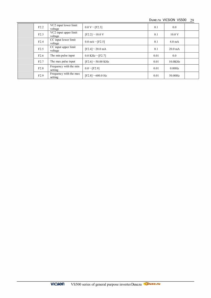
F2.2 VC2 input lower limit voltage 0.0 V~[F2.3] 0.1 0.0
F2.3 VC2 input upper limit voltage [F2.2]~10.0 V 0.1 10.0 V
F2.4 CC input lower limit voltage 0.0 mA~[F2.5] 0.1 4.0 mA
F2.5 CC input upper limit voltage [F2.4]~20.0 mA 0.1 20.0 mA
F2.6 The min pulse input 0.0 KHz~[F2.7] 0.01 0.0
F2.7 The max pulse input [F2.6]~50.00 KHz 0.01 10.0KHz
F2.8 Frequency with the min setting 0.0~[F2.9] 0.01 0.00Hz
F2.9 Frequency with the max setting [F2.8]~600.0 Hz 0.01 50.00Hz

VICSION VS500
VS500 series of general purpose inverter Duxe.ru
30
Function Code Name Setting range Minimum Setting
Manufacture Setting
Modify Limit
F2.10 Characteristics selection of input channel
The first part of LED (form right to left) : (VC1channel) 0: positive characteristics
1: Negative characteristics
The second part of LED:(VC2 channel)
0: positive characteristics
1: Negative characteristics
The third part of LED:(CC channel)
0: positive characteristics
1: Negative characteristics
The fourth part of LED:(pulse channel)
0: positive characteristics
1: Negative characteristics
1 0000 ★
F2.11 External freq. set time constant of filtering
0.01~1.00 Sec 0.01 0.10
F2.12 Combination setting mode Refer to the explanations about F2.12 1 0
F2.13 Analog output selection (AO1、AO2)
The first part of LED (form right to left):AO1output 0:Output freq.
1:Output current 2:Output voltage 3:Rotate speed of applied motor
4:PID setting
5:PID feedback
The second part of LED:AO2 output
0:Output freq.
1:Output current
2:Output voltage
3:Rotate speed of applied motor
4:PID setting
5:PID feedback
The third and fourth part of LED:Reserved
1 0010
F2.14 The lower limit of analog output AO1
0.0~[F2.15] 0.1 0.0 V
F2.15 The upper limit of analog output AO1
[F2.14]~12.0 0.1 10.0 V
F2.16 The lower limit of analog output AO2
0.0~[F2.17] 0.1 2.0 V
F2.17 The upper limit of analog output AO2
[F2.16]~12.0 0.1 12.0 V
F2.18 Reserved
Ana
log
I/O p
aram
eter
uni
t

Duxe.ru VICSION VS500
VS500 series of general purpose inverter Duxe.ru
31
Function Code Name Setting range Minimum Setting
Manufacture Setting
Modify Limit
F3. 0 Function selection of input terminal 1 (0~26)
0:Control terminal is idle
1:Multi-speed control terminal 1
2:Multi-speed control terminal 2
3:Multi-speed control terminal 3
4:Wobble freq. is valid
5:State of wobble freq. reset
6:FWD jog control
7:REV jog control
8:Acc& Dec time selection terminal 1
9:Acc& Dec time selection terminal 2
10:Freq. setting channel selection 1
11:Freq. setting channel selection 2
12:Freq. setting channel selection 3
13:Freq. is controlled gradually increase (UP)
14:Freq. is controlled gradually decrease (DW)
15:UP-DW freq. clear
16:Uncontrolled stop control
17:Fault signal of peripheral equipment input 18:Three-line mode running control
19:DC braking control
20:Inner counter clear
21:Inner counter timer
22:PLC running valid
23:PID running valid
24:Internal timer trigger terminal
25:PLC state reset after stopping
26:Multi-speed control terminal 4
1 1 ★
F3. 1 Function selection of input terminal 2 (0~26) 1 2 ★
F3. 2 Function selection of input terminal 3 (0~26) 1 3 ★
F3. 3 Function selection of input terminal 4 (0~26) 1 6 ★
F3. 4 Function selection of input terminal 5 (0~26) 1 13 ★
F3. 5 Function selection of input terminal 6 (0~26) 1 14 ★
F3. 6 Output terminal OC1
0:In the running
1:Frequency reaching
2:Freq. level detection signal(FDT)
3:Over-loading alarm
4:External fault halt
5:Output frequency reaches the upper-limit
6:Output frequency reaches the lower-limit
7:Running in zero speed
8:Internal timer reaches the setting time
1 2
F3. 7 Output terminal OC2 1 1
Dig
ital O
/I pa
ram
eter
uni
t

VICSION VS500
VS500 series of general purpose inverter Duxe.ru
32
F3. 8 TA, TB and TC of relay contacts
9:PLC stage is end of run
10:PLC periodic is end of run
11:Internal timer arrive regular time
12:Setting value of counter arrives
13:Designated value of counter arrives
14:Deceleration running
15:Reserved
16:Inverter fault
17:Restrictions on wobble freq. of the upper and lower limit freq. 18:Reserved
1 16
F3. 9 Frequency reach the checkout amplitude 0.0~20.00 Hz 0. 01 5.00
F3. 10 FDT setting 1 0.0~the upper limit freq. 0.01 10.00
F3. 11 FDT output delay time 1 0.0~200.0 Sec 0.1 2.0 ★
F3. 12 FDT setting 2 0.0~the upper limit freq. 0.01 10.00
F3. 13 FDT output delay time 2 0.0~200.0Sec 0.1 2.0 ★
Duxe.ru VICSION VS500
VS500 series of general purpose inverter Duxe.ru
33
Function Code Name Setting range Minimum Setting
Manufacture Setting
Modify Limit
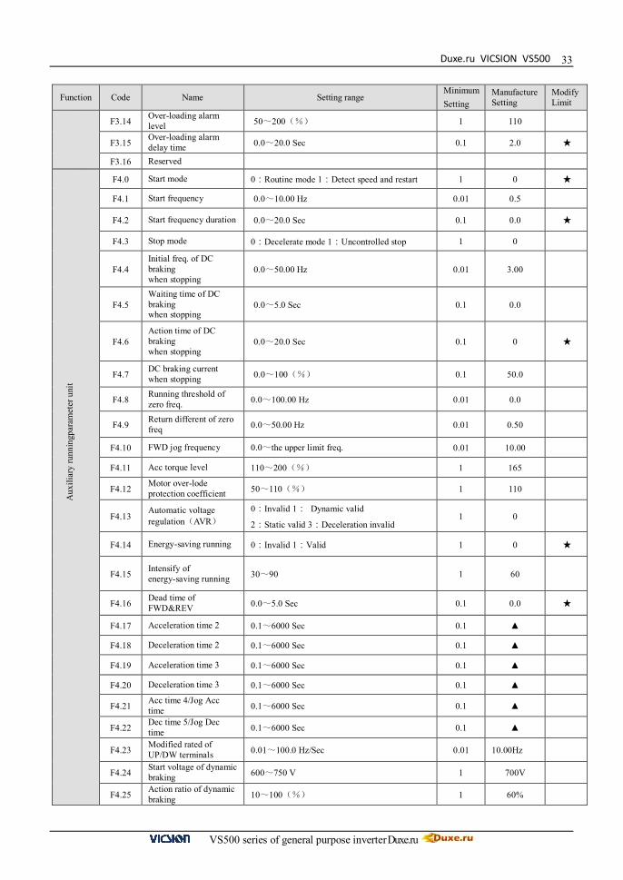
F3.14 Over-loading alarm level 50~200(%) 1 110
F3.15 Over-loading alarm delay time 0.0~20.0 Sec 0.1 2.0 ★
F3.16 Reserved
F4.0 Start mode 0:Routine mode 1:Detect speed and restart 1 0 ★
F4.1 Start frequency 0.0~10.00 Hz 0.01 0.5
F4.2 Start frequency duration 0.0~20.0 Sec 0.1 0.0 ★
F4.3 Stop mode 0:Decelerate mode 1:Uncontrolled stop 1 0
F4.4 Initial freq. of DC braking when stopping
0.0~50.00 Hz 0.01 3.00
F4.5 Waiting time of DC braking when stopping
0.0~5.0 Sec 0.1 0.0
F4.6 Action time of DC braking when stopping
0.0~20.0 Sec 0.1 0 ★
F4.7 DC braking current when stopping 0.0~100(%) 0.1 50.0
F4.8 Running threshold of zero freq. 0.0~100.00 Hz 0.01 0.0
F4.9 Return different of zero freq 0.0~50.00 Hz 0.01 0.50
F4.10 FWD jog frequency 0.0~the upper limit freq. 0.01 10.00
F4.11 Acc torque level 110~200(%) 1 165
F4.12 Motor over-lode protection coefficient 50~110(%) 1 110
F4.13 Automatic voltage regulation(AVR)
0:Invalid 1: Dynamic valid
2:Static valid 3:Deceleration invalid 1 0
F4.14 Energy-saving running 0:Invalid 1:Valid 1 0 ★
F4.15 Intensify of energy-saving running 30~90 1 60
F4.16 Dead time of FWD&REV 0.0~5.0 Sec 0.1 0.0 ★
F4.17 Acceleration time 2 0.1~6000 Sec 0.1 ▲
F4.18 Deceleration time 2 0.1~6000 Sec 0.1 ▲
F4.19 Acceleration time 3 0.1~6000 Sec 0.1 ▲
F4.20 Deceleration time 3 0.1~6000 Sec 0.1 ▲
F4.21 Acc time 4/Jog Acc time 0.1~6000 Sec 0.1 ▲
F4.22 Dec time 5/Jog Dec time 0.1~6000 Sec 0.1 ▲
F4.23 Modified rated of UP/DW terminals 0.01~100.0 Hz/Sec 0.01 10.00Hz
F4.24 Start voltage of dynamic braking 600~750 V 1 700V
F4.25 Action ratio of dynamic braking 10~100(%) 1 60%
Aux
iliar
y ru
nnin
gpar
amet
er u
nit

VICSION VS500
VS500 series of general purpose inverter Duxe.ru
34
Function Code Name Setting range Minimum Setting
Manufacture Setting
Modify Limit
F4.26 Restart after power down setting
The first part of LED:
0:Invalid 1:Valid
The second part of LED:
0:Routine mode
1:Detect speed and restart mode
The third and fourth part of LED:Reserved
1 0010 ★
F4.27 Waiting time of restart after power
0.0~10.0 Sec 0.1 0.5 ★
F4.28 REV jog frequency 0.0~the upper limit freq. 0.01 10.00
F5. 0 Multi-speed running mode
The first part of LED(form right to left):Simple PLC selection 0:Simple PLC is invalid. 1:Simple PLC is valid
2:Simple PLC is conditional valid
The second part of LED:Simple PLC running mode selection 0:Single loop mode
1:Single loop and stop mode
2:Continuous loop mode
3:Continuous loop and stop mode
4:Keep the end value
5:Keep the end value and stop mode The third part of LED 0:Restart from the first stage freq.
1:Restart from running freq., which is saved before running is break 2:Restart from setting freq. when running is break. The fourth part of LED:PLC save state
0:Non-save after power off
1:Save after power off
1 0000 ★
F5.1 Multi-speed frequency 1 0.0~the upper limit freq 0.01 35.00
F5.2 Multi-speed frequency 2 0.0~the upper limit freq 0.01 15.00
F5.3 Multi-speed frequency 3 0.0~the upper limit freq 0.01 3.00
F5.4 Multi-speed frequency 4 0.0~the upper limit freq 0.01 20.00
F5.5 Multi-speed frequency 5 0.0~the upper limit freq 0.01 25.00
F5.6 Multi-speed frequency 6 0.0~the upper limit freq 0.01 30.00
F5.7 Multi-speed frequency 7 0.0~the upper limit freq 0.01 35.00
F5.8 Multi-speed frequency 8 0.0~the upper limit freq 0.01 40.00
F5. 9 Multi-speed frequency 9 0.0~the upper limit freq 0.01 35.00
F5.10 Multi-speed frequency 10 0.0~the upper limit freq 0.01 15.00
F5.11 Multi-speed frequency 11 0.0~the upper limit freq 0.01 3.00
F5.12 Multi-speed frequency 12 0.0~the upper limit freq 0.01 20.00
F5.13 Multi-speed frequency 13 0.0~the upper limit freq 0.01 25.00
Aux
iliar
y ru
nnin
gpar
amet
er u
nit
Mul
ti-sp
eed
runn
ing
para
met
er u
nit

Duxe.ru VICSION VS500
VS500 series of general purpose inverter Duxe.ru
35
F5.14 Multi-speed frequency 14 0.0~the upper limit freq 0.01 30.00
F5.15 Multi-speed frequency 15 0.0~the upper limit freq 0.01 35.00

VICSION VS500
VS500 series of general purpose inverter Duxe.ru
36
Function Code Name Setting range Minimum Setting
Manufacture Setting
Modify Limit
F5.16 Running time of Multi-speed 1 0.0~6000 Sec 0.1 10.0
F5.17 Running time of Multi-speed 2 0.0~6000 Sec 0.1 10.0
F5.18 Running time of Multi-speed 3 0.0~6000 Sec 0.1 10.0
F5.19 Running time of Multi-speed 4 0.0~6000 Sec 0.1 10.0
F5.20 Running time of Multi-speed 5 0.0~6000 Sec 0.1 10.0
F5.21 Running time of Multi-speed 6 0.0~6000 Sec 0.1 10.0
F5.22 Running time of Multi-speed 7 0.0~6000 Sec 0.1 10.0
F5.23 Running time of Multi-speed 8 0.0~6000 Sec 0.1 10.0
F5.24 Running direction of PLC multi-speed
The first part of LED(form right to left):
0: Stage 1 FWD 1:Stage 1 REV
The second part of LED:
0: Stage 2 FWD 1:Stage 2 REV
The third part of LED:
0: Stage 3 FWD 1:Stage 3 REV
The fourth part of LED:
0: Stage 4 FWD 1:Stage 4 REV
1 0000
F5.25 Running direction of PLC multi-speed
The first part of LED(form right to left):
0: Stage 5 FWD 1:Stage 5 REV
The second part of LED:
0: Stage 6 FWD 1:Stage 6 REV
The third part of LED:
0: Stage 7 FWD 1:Stage 7 REV
The fourth part of LED:
0: Stage 8 FWD 1:Stage 8 REV
1 0000
F5.26 PLC timing running shutdown
0: Invalid
1~9999(min) :timing running time 1 0
F6.0 Internal timer 0.1~6000.0 Sec 0.1 10.0
F6.1 Fault self-recovery time 0,1,2 1 0 ★
F6.2 Interval time of fault self-recovery 0.2~20 Sec 0.1 2.0 ★
F6.3 Final value setup of internal counter 1~60000 1 1 ★
F6.4 Internal timer setup 1~60000 1 1 ★
F6.5 Skip freq. 1 0.0~the upper limit freq. 0.01 0
F6.6 Amplitude accumulation of Skip freq. 1
0.0~5.00 Hz 0.01 0
F6.7 Skip freq. 2 0.0~the upper limit freq. 0.01 0
F6.8 Amplitude accumulation of Skip freq. 2
0.0~5.00 Hz 0.01 0
F6.9 Linear speed coefficient setting 0.01~100.0 0.01 1.00
Mul
ti-sp
eed
runn
ing
para
met
er u
nit
Adv
ance
d ru
nnin
g pa
ram
eter
uni
t

Duxe.ru VICSION VS500
VS500 series of general purpose inverter Duxe.ru
37
F6.10 Close-loop analog coefficient setting 0.01~100.0 0.01 1.00
F6.11 Rotator speed coefficient setting 0.01~10.00 0.01 1.00
F6.12 Monitor item selection 1 / Main display 0~11 1 0

VICSION VS500
VS500 series of general purpose inverter Duxe.ru
38
Function Code Name Setting range Minimum Setting
Manufacture Setting
Modify Limit
F6.13 Monitor item selection 2 / Auxiliary display 0~19 1 1
F6.14 Query or modify parameters 0~9999 1 1700
F6.15 Parameter initialization
0:Parameter initialization is off.
1:Parameter initialization is on.
2:Clean fault records
3:complete initialization
1 0 ★
F6.16 Copy parameter function 0:Copy forbidden 1:Copy allowed 1 0
F6.17 Manufactory password 0~9999 1 1500
F6.18 User password 0~9999 1 0
F6.19 Reference password 0~9999 1 ◆
F7.0 Wobble freq. running mode
The first part of LED (form right to left) :
0:Function of wobble freq. is invalid.
1:Function of wobble freq. is valid.
2:Function of wobble freq. is conditional valid. The second part of LED: restart mode 0: Restart according to parameters saved before stop 1: Restart The third part of LED: wobble freq. characteristics 0:The wobble freq. is fixed
1:The wobble freq. is changeable. The fourth part of LED: Storage characteristics of wobble freq. 0:It will not save the running state of wobble freq. after power off 1:It will save the running state of wobble freq. after power off
1 0000 ★
F7.1 Preset freq. of wobble freq. 0.0~the upper limit freq 0.01 10.00
F7.2 Waiting time of preset freq. 0.0~6000.0 Sec 0.1 0.0 ★
F7.3 Amplitude of wobble freq. 0.0~50.0(%) 0.1 10.0
F7.4 Jumping freq 0.0~80.0(%) 0.1 10.0
F7.5 Triangular rise time 0.1~1000.0 Sec 0.1 10.0
F7.6 Triangular fall time 0.1~1000.0 Sec 0.1 10.0
F7.7 Preset center freq. of wobble freq. 0.0~the upper limit freq 0.01 10.0
F7.8 Reserved
Adv
ance
d ru
nnin
g pa
ram
eter
uni
t W
obbl
e fre
q. ru
nnin
g pa
ram
eter
uin
t

Duxe.ru VICSION VS500
VS500 series of general purpose inverter Duxe.ru
39
Function Code Name Setting range Minimum Setting
Manufacture Setting
Modify Limit
F8.0 Inner P ID control
The first part of LED(form right to left): Inner PID control 0:Inner PID control is invalid
1:Inner PID control is valid
2:Inner PID control is conditional valid.
The second part of LED: PID controller selection 0: proportion 1:Integral
2:Proportion and integral
The third part of LED: Regulating property of PID controller 0: positive interaction 1:Reactor The fourth part of LED: 0: Single polar PID control 1: Bi-polar PID control
1 0020 ★
F8.1 Inner PID setting and channel selection
The first part of LED(form right to left):
0:Digital setting. It is set by parameter F8.2.
1:Serials interface setting
2:Panel potentiometer setting, it is on the operation panel. 3:External voltage signal VC1(0V~5V)。
4:External voltage signal VC2(0V~10V)。
5:External current signal CC(0~20mA)。
The second part of LED: Reserved.
The third part of LED: It is used to set PID feedback channel. 0:External voltage input VC1
1:External voltage input VC2
2:External current input CC
3:Pulse input PLS 4:VC1+CC
1 0000 ★
F8.2 Inner PID close-loop digital setting 0.00~10.00 V 0.01 0.00
F8.3 Minimum fixed value 0.0~[F8.4] 0.01 0.0
F8.4 Maximum fixed value [F8.3]~10.00 0.01 10.00
F8.5 Feedback of minimum fixed value 0.0~10.00 0.01 0.0
F8.6 Feedback of maximum fixed value 0.0~10.00 0.01 10.00
F8.7 Proportion gain 0.0~5.00 0.01 1.00
F8.8 Integration time constant 0.1~100.0 Sec 0.1 50.0
F8.9 Allowable deviation limit 0.0~20.0(%) 0.1 5.0
F8.10 Preset freq. for close-loop 0.0~the upper limit freq. 0.01 0.0
F8.11 Holding time of preset freq. for close-loop
0.0~6000.0 Sec 0.1 0.0 ★
F8.12 Long-distance manometer range 0.001~20.000 Mpa 0.001 1.000
F8.13 Sleeping threshold [F8.14]~10.00V 0.01 10.00
PID
con
trol p
aram
eter
uni
t

VICSION VS500
VS500 series of general purpose inverter Duxe.ru
40
F8.14 Awakening threshold 0.01~[F8.13] 0.01 0.0

Duxe.ru VICSION VS500
VS500 series of general purpose inverter Duxe.ru
41
Function Code Name Setting range Minimum Setting
Manufacture Setting
Modify Limit
F8.15
Switching time of Sleeping/Awakening mode
5.0~500.0 Sec 0.1 300.0
F8.16 Upper limit pressure value [F8.17]~[F8.12] 0.001 1.000
F8.17 Lower limit pressure value 0.001~[F8.16] 0.001 0.0
F8.18 …
F8.24 Reserved
F9.0 Communication setting
The first part of LED(form right to left): It is used to set baud rate of serials communication. 0: Reserved 1:1200bps 2: 2400bps 3: 4800bps 4: 9600bps 5: 19200bps The second part of LED: To set data format of serials communication. 0:Close 1: Even 2:Odd The third and fourth part of LED: Reserved.
1 0114 ★
F9.1 Local address
0~30 1 1
F9.2 Response delay of local 0~1000 ms 1 5ms
F9.3 Function setting of communication Auxiliary function
The first part of LED(form right to left):
0:The inverter is guest 1: The inverter is host The second part of LED: Act selection after communication is lost 0:Stop 1:Keep
The third part of LED:linkage jog
0:jog synchronized
1:jog asynchronous
The fourth part of LED:linkage control synchronized frequency source
1 0010
F9.4 Checkout time of communication overtime
0.0~100.0 Sec 0.1 10.0
F9.5 Linkage setting proportion 0.010~10.000 0.01 1.000
F9.6 Rectify channel of linkage setting proportion
0:close 1:Panel potentiometer
Rectify channel 2:External voltage signal VC1
(0 ~ 5V)
Rectify channel 3:External voltage signal VC2
(0 ~ 10V)
Rectify channel 4:External current signal CC
(0 ~ 20mA)
1 0
F9.7 Setting channel of slave machine auxiliary freq.
0:No auxiliary freq.
1:Panel potentiometer
2:External voltage signal VC1(0 ~ 5V)
3:External voltage signal VC2(0 ~ 10V)
4:External current signal CC
1 0
F9.8 Amplitude of auxiliary freq. 0.0~25.00 Hz 0.01 5.00
PID
con
trol
para
met
er u
nit
Se
rials
com
mun
icat
ion
para
met
ers
VICSION VS500
VS500 series of general purpose inverter Duxe.ru
42
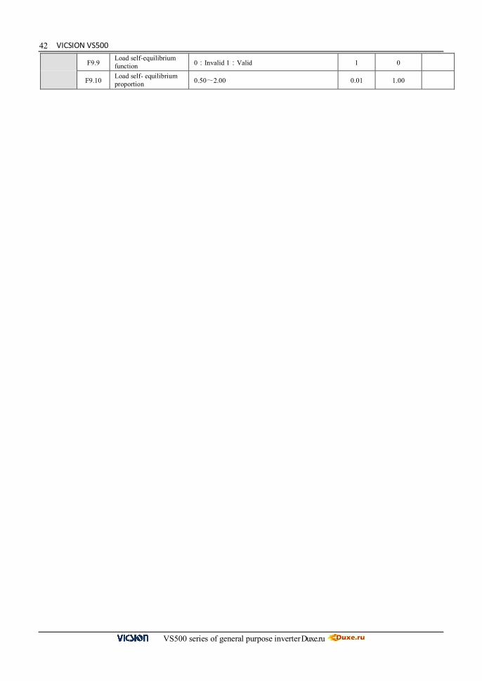
F9.9 Load self-equilibrium function 0:Invalid 1:Valid 1 0
F9.10 Load self- equilibrium proportion 0.50~2.00 0.01 1.00

Duxe.ru VICSION VS500
VS500 series of general purpose inverter Duxe.ru
43
Function Code Name Setting range Minimum Setting
Manufacture Setting
Modify Limit
F9.11 Trimming range of load self equilibrium freq.
0.0~5.00 0.01 2.00
FC.0 Under voltage protection level 360~460 V 1 380
FC.1 Over voltage limit level 660~760 V 1 720
FC.2 Current amplitude limiting level 150~200(%) 1 190
FC.3 Reserved
FC.4 Reserved
FC.5 Action function selection
The first part of LED(form right to left): Cooling fan control 0:Cooling fan run after inverter run.
1:Cooling fan will automatic run when inverter is power on. The second part of LED: Variable speed control of cooling fan 0:Invalid 1:Valid
1 1100
FC.6 Auxiliary function
The first part of LED(form right to left):Forbid modify parameters function 0:Invalid 1:Valid
The second part of LED:Input terminal effective level 0:Low level (terminals is connected) 1:High level (terminals is disconnected ) The third part of LED: Reserved The fourth part of LED:selection of rotate speed display proportion 0: the coefficient of rotate speed display is valid 1: the deceleration proportion is valid
1 0000
FC.7 Reserved
FC.8 Agency password 0~9999 1 100
FC.9 Reserved
FC.10 Reserved
FC.11 Oscillatory inhibiting factor 0.00~2.00 0.01 0.00
FC.12 Reserved
FC.13 Program version 1600~1699 1 ▲
Spec
ial f
unct
ion
para
met
er u
nit

VICSION VS500
VS500 series of general purpose inverter Duxe.ru
44
6.DESCRIPTION OF SPECIFIC FUNCTIONS
(General parameter: [F0.0] =0000) 6.1 Basic operation parameter unit It is used for selecting the running mode of inverter. Inverter is able to switch between the mode of general running and mode of dedicated drawing machine through changing the setting of first part of LED. And the parameters list and soft function mode have been operated. The first part of LED(form right to left): 0: General mode (General parameter is valid.)
1: Dedicated drawing machine mode (Drawing machine parameter is valid.)
If the setting of parameter has changed, there would be a process of initialization; meantime, it would be shifted to the corresponding parameter environment. Meanwhile, this parameter cannot be initialized. Please refer to the Seventh Chapter to use parameters. The first part of LED(form right to left):Reserved It is used for selecting the running mode of inverter. Inverter is able to switch between the mode of general running and mode of dedicated drawing machine through changing the setting of first part of LED. And the parameters list and soft function mode have been operated. The first part of LED(form right to left): 0: General mode (General parameter is valid.)
1: Dedicated drawing machine mode (Drawing machine parameter is valid.)
If the setting of parameter has changed, there would be a process of initialization; meantime, it would be shifted to the corresponding parameter environment. Meanwhile, this parameter cannot be initialized. Please refer to the Seventh Chapter to use parameters. The first part of LED(form right to left):Reserved It is used for selecting input channel of frequency instruction. 0: Frequency setting by operation panel Frequency of inverter is set by parameter F0.2 as well as by the key and on the operation panel in normal monitor mode. 1: UP/DW Acc and Dec control Running frequency is set by terminals UP and DW. And controlled terminals UP and DW can be selected by parameters [F3.0] ~ [F3.5]. When UP is on, the running frequency will increase. When UP is on, the running frequency will decrease. When UP and DW is on or off together with CM, running frequency will fix. The rate of modified frequency of terminals UP and DW is set by parameter F4.23. 2: RS485 interface Through serial communication, it receives instruction of setting frequency from PC or the master. 3: Panel potentiometer Running frequency can be set by potentiometer on the operation panel. 4: External voltage signal VC1 Running frequency is set by external voltage signal VC1. (VC1 is form 0.0 to 5.0V) Please set the VC1 referring to
F0.0 Choosing the running mode Setting range:0000 ~ 0001
F0.1 Frequency input channel / mode selection Setting range:0 ~ 9

Duxe.ru VICSION VS500
VS500 series of general purpose inverter Duxe.ru
45the parameters F2.0 and F2.1. 5: External voltage signal VC2 Running frequency is set by external voltage signal VC2. (VC2 is form 0.0 to 10.0V) Please set the VC2 referring to the parameters F2.2 and F2.3. 6: External current signal CC Running frequency is set by external current signal CC. (CC is form 0.0 to 20.0mA) Please set the CC referring to the parameters F2.4 and F2.5. 7: External pulse signal Running frequency is set by external pulse signal. (It is form 0.0 to 350.0 KHz, and the amplitude accumulation is form 5 to 30V) Please set the pulse signal referring to the parameters F2.6 and F2.7. 8: Combination setting Running frequency is set by linear combination of each channel, and combination mode is decided by parameter F02.12. 9: External terminals External terminals set input channel of frequency. And it can be set by parameters F3.0~F3.5.
Freq. Setting terminal 3 Freq. Setting terminal 2 Freq. Setting terminal 1 Freq. Setting channel
0 0 0 Frequency setting by operation panel 0 0 1 UP/DW Acc and Dec control 0 1 0 RS485 interface 0 1 1 Panel potentiometer 1 0 0 External voltage signal VC1 1 0 1 External voltage signal VC2 1 1 0 External current signal CC 1 1 1 External pulse signal
When F0.1 is 0, Frequency digital setting controls output frequency of inverter. In normal monitor state, user can use the key and to modify this parameter. As for F0.1 is 1 or F0.1 is 2, the frequency will save in parameter F0.3 after power off, if F0.3 is 00#0
It is used for making sure that the frequency is set under the stopping or power off situation. When F0.1 is 0, 1 or 2, set parameter F0.3 to ensure that setting freq. is or not be saved in F0.2. The first part of LED(form right to left): 0: Inverter will run in setting freq. that is storage in F0.2 after stopping 1: Setting freq. will lost after stopping. And inverter will run in 0.0Hz when restarting The second part of LED(form right to left): 0:Setting freq. is kept when stopping 1:Setting freq. will save in F0.2 when stopping 2:Setting freq. is cleared when stopping The third and fourth part of LED(form right to left):Reserved.
F0.2 Frequency digital setting Setting range:0.0 ~ the upper limit frequency
F0.3 Auxiliary control of freq. digital setting Setting range:0000 ~ 0021

VICSION VS500
VS500 series of general purpose inverter Duxe.ru
46
,
It is used for selecting operation channel of inverter and function of key . The first part of LED (form right to left): to select operation channel of inverter. 0: Keypad control The inverter is controlled by key , and on the keypad. And FWD state will affect output phase sequence of inverter. When FWD is on with CM, output phase sequence will reverse with setting sequence, contrariwise, output phase sequence will go the same way with setting sequence. 1: External terminals control The inverter receives running instruction from external terminals FWD, REV and CM. The manufacture setting is shown as follows.
Instruction STOP Instruction FWD REV
Terminals State
2: RS485 interface Through serial communication, it receives instruction of setting frequency from PC or the master
The second part of LED (form right to left): to select function of the key. 0: It is valid for panel control. When F0.4 is 0, Stop key on the operation panel is available. 1: It is valid for all kinds of control method. When F0.4 is not 0 and press stop key, inverter will emergency stop and twinkling display Fu.16. The third and fourth part of LED(form right to left):Reserved. It is used for setting control mode of external terminals.
0:Two-line mode 1 (default setting) Instruction STOP Instruction FWD REV
Terminals State
0:Two-line mode 2
Instruction STOP Instruction run FWD REV
Terminals State
F0.4 Operation channel selection Setting range: 0000 ~ 0012
FWD REV CM
FWD REV CM
FWD REV CM
FWD REV CM
F0.5 Combination methods of instruction terminals Setting range:0 ~ 2
This parameter will be valid only when F0.4 is set as ###1
FWD REV CM
FWD REV CM
FWD REV CM
FWD REV CM
FWD
CM
FWD
CM
REV
CM
REV
CM

Duxe.ru VICSION VS500
VS500 series of general purpose inverter Duxe.ru
472:Three- line mode Please select a three-line mode terminal to set three-line mode. (Refer to description of parameters F3.0 ~ F3.5) X?is three-line mode terminals,and it is any one among terminals X1 ~ X6 Switch function is shown as follow:
1. SW1 —— Stop trigger switch of inverter
2. SW2 —— FWD trigger switch
3. SW3 —— REV trigger switch It is used for changing the output phase-sequence of inverter, which changes the operating direction of motor (set by binary system)
The third part of LED:External operation channel auxiliary function 0:Self-starting is forbidden when inverter is just power-on 1:Self-starting is allowed when inverter is just power-on
When [F0.6]=#0##,when inverter is just power-on,even though the control terminal is in running,the inverter will not self-starting. In order to operate inverter, you should first give a stop signal, then a start-up instruction. This parameter is used for modifying the present output phase sequence of inverter, which modifies the running motor direction. Control effect of panel control method is shown as following table.
FWD-CM [F0.6] Direction
OFF # # 1 # FWD
ON # # 1 # FWD OFF # # 0 0 FWD OFF # # 0 1 REV
ON # # 0 0 REV
ON # # 0 1 FWD
When setting freq. is lower than lower limit freq., the inverter will run in lower limit freq. But the parameters F4.8 and F4.9 are priority over F0.7 and F0.8.
SW1
SW2
SW3
X?
FWD
REV
CM
Fig.6-1 three-line mode wiring
Output freq
t
SW1
SW2
SW3
Fig.6-2 output freq when three-line
F0. 6 Running direction control and instruction auxiliary setting Setting range:0000 ~ 0111
Parameter F0.4 is valid together with direction control of external terminals.
F0.7 The lower limit frequency Setting range:0.0 ~ [F0.8] Hz F0.8 The upper limit frequency Setting range:[F0.7] ~600.00Hz
F0.9 Reserved

VICSION VS500
VS500 series of general purpose inverter Duxe.ru
48
Acc time 1 is the time of output frequency accelerating from 0.0 Hz to 50.00Hz. Dec time 1 is the time of output frequency decelerating from 50.00 Hz to 0.00Hz. Units of Acc and Dec are set by parameter F0.12 The first part of LED(form right to left):It is used for setting curve type when inverter is accelerating or decelerating, shown as fig6-3. 0: Beeline Output freq. of inverter will increase or decrease according to fixed rated. 1: S curve Output freq. of inverter will increase or decrease according to graded rated. Characteristic of S curve is set by parameter F0.13 and F0.14. The second part of LED:To set Acc/Dec method 0: Output freq. will be modified according to Acc/Dec time. 1: Output freq. will be automatically modified according to load. The third part of LED: It is used for setting unit of Acc/Dec time, namely unit of parameters F0.10, F0.11, F4.17, F4.18, F4.19, F4.20, F4.21 and F4.22. 0: Sec. 1: Minute The fourth part of LED:Reserved Parameters F0.13 and F0.14 define characteristic of S curve. It is totally divide into three sections, shown as fig6-3. Acc/Dec initial section is process that slope of output freq. is gradual increase from 0. The slope will fix in Acc/Dec ascending/decline section. And the slope will gradual decrease to 0 in end section. 0: General purpose load. 1: Fan and pump load.
F0.10 Acc time 1 Setting range:0.1 ~ 6000 Sec/Min F0.11 Dec time 1 Setting range:0.1 ~ 6000 Sec/Min
F0.12 character parameter of Acc and Dec Setting range:0000 ~ 0111
S curve
line
t(Sec/min)
O utp ut freq(Hz)
[F0.13] [F0.14]
Fig.6-3 Acc/Dec curve
F0.13 Acc/Dec initial section proportion of S curve Setting range:10.0 ~ 50.0(%) F0.14 Acc/Dec ascending/decline section proportion of S curve Setting range:10.0 ~ 80.0(%)
F0.15 Load pattern selection Setting range:0,1

Duxe.ru VICSION VS500
VS500 series of general purpose inverter Duxe.ru
49
Carrier wave frequency influences audio-frequency noise and calorific effect in running. When environmental temperature is too high and motor’s load is too heavy, carrier frequency should be decreased properly to improve the heat thermal performance. It is used for setting correlated characteristics about carrier wave.
The first part of LED (form right to left): Reserved The second part of LED:Load relating carrier wave adjustment.
If this function is valid, when load current is too high, it will automatically reduce the carrier frequency to ensure operation safety of inverter.
0:Invalid 1:Valid The third part of LED:Heat relating carrier wave adjustment
If this function is valid, when environmental temperature is too high, the inverter will automatically reduce the carrier wave frequency.
0:Invalid 1:Valid The fourth part of LED:Freq. relating carrier wave adjustment
If this function is valid, the inverter will automatically reduce the carrier frequency in low-frequency running. 0:Invalid 1:Valid
Attention:When the inverter automatically adjusts carrier freq., the running noise will increase It is used for preventing error modify about data. 1:Forbid to modify all parameter, except F0.2 and F0.18 2:Forbid to modify all parameter, except F0.18
6.2 Primary application of parameter unit
0:Constant torque curve The output voltage of inverter is in direct ratio to the output frequency, and most load take this mode. 1: low-freq. torque curve 1 The output voltage of inverter is conic with the output frequency, which is suited to the fan and pump load. 2: low-freq. torque curve The output voltage of inverter is conic with the output frequency, which is suited to the constant power load, such as
F0.16 Carrier wave frequency Setting range: 1.5 ~ 10.0 KHz
F0.17 Carrier wave characteristics Setting range:0000 ~ 1110
F0.18 Parameter write-protect Setting range:1,2
Parameter F0.4 is valid together with direction control of external terminals.
The parameter sets [F1.0]-[F1.10] are used for setting V/F curve during V/F control mode. V/F curve type (parameter [F1.0]) can be freely selected and set according to the load type. To solve the defect that the low-frequency torque of V/F control method is insufficient, setting of the torque compensation can boost the output torque, and substantially increase the output voltage value of the inverter to enhance the output current of the inverter; the torque boosting function can be specifically set according to [F1.1]-[F1.2] parameters. Parameters [F1.5]-[1.10] are used for determining the curve setting during customized output of V/F curve, and please refer to the parameter description for the details
F1.0 Type of V/F Curve Setting range :0 ~ 3

VICSION VS500
VS500 series of general purpose inverter Duxe.ru
50
Boost voltage
f
[F1.3]
Voltage
[F1.4]
[F1.1]
(2)Constant torque curve
fan, pump, etc. If there is some unstable phenomenon in light-load running, please switch to run in the decreasing torque curve 1. 3: V/F user-defined curve It is used for setting user-defined curve which user need It is used for improving the low-frequency torque character. In low-frequency running, it will make boost compensation for the output voltage of inverter, as shown in Fig.6-5. 0:Manual Torque boost voltage is completely controlled by F1.1. There are two features: voltage will steady boost. And motor will easily magnetic saturation when light-load. 1:Automatic Torque boost voltage is changed with the stator current of motor. The boost voltage is higher with the stator current higher.
Voltage
Constant torque curve Decreasing torque
curve 1
Decreasing torque
curve 2
[F1.4]
[F1.3] Basic running freq
f
The max
tput voltage
Fig. 6-4 V/F curve
F1.1 Torque Boost(output voltage at 0 Hz) Setting range:0.0 ~ 20.0(%)
Boost voltage = × [F1.4] [F1.1]
100
Voltage
Boost voltage
f
[F1.3]
[F1.4]
(1)Decreasing torque curve
[F1.1]
Fig.6-5 Torque boost
F1.2 Torque boost pattern Setting range:0 ,1
Boost voltage = ×[F1.4]× Inverter’s output Current 2×inverter’s rated current
[F1.1]
200

Duxe.ru VICSION VS500
VS500 series of general purpose inverter Duxe.ru
51
Freq
Voltage
[F1.6]
[F1.8]
[F1.10]
[F1.1]
[F1.9] [F1.7] [F1.5]
[F1.4]
[F1.3]
Auto torque boost can prevent the magnetic saturation, as the boost voltage is too high with light load, which can avoid the over-heat phenomenon of motor in low frequency running. Basic running frequency is corresponding to minimum frequency when output voltage of inverter is the highest. Usually, it is rated frequency of motor. Max output voltage is corresponding to output voltage when inverter outputs the basic running frequency. Usually, it is rated voltage of motor. Those parameters are used for setting user-defined curve which user need. Shown as Fig.6-6 below:
This functional parameter is used for occasion that the inverter needs braking before starting, and please refer to Fig. 6-7. [F1.11] defines the percentage of DC braking against the rated current of inverter during start of inverter
Parameter F1.12 defines duration that inverter output DC braking current. When F1.12 is 0, DC braking is invalid when starting.
F1.3 Base running frequency Setting range: 5.00 ~ the upper frequency
F1.4 Max output voltage Setting range: 200 ~ 500V/100~250V
F1.5 V/F freq. 3 Setting range: F1.7] ~ [F1.3] F1.6 V/F voltage 3 Setting range:[F1.8] ~ 100% F1.7 V/F freq. 2 Setting range: [F1.9] ~ [F1.5] F1.8 V/F voltage 2 Setting range:[F1.10] ~ [F1.6] F1.9 V/F freq. 1 Setting range:0.0 ~ [F1.7] F1.10 V/F voltage 1 Setting range:[F1.1] ~ [F1.8]
Fig.6-6 V/Fuser-defined curve
F1.11 DC braking current when starting Setting range:0.0 ~ 100.0(%)
F1.12 DC braking time when starting Setting range:0.0 ~ 20.0 S
When rated current of motor is lower than rated current of inverter, please pay attention to set,F1.11.Make sure that DC braking current is lower than rated current of motor

VICSION VS500
VS500 series of general purpose inverter Duxe.ru
52
Torque (Relative value)
Rotate speed(Relative value
100
100-[F1.14]
[F1.15] [F1.16]
The actual slip of motor will change with the load change. The inverter, through setting of this functional parameter, will automatically regulate its output frequency according to the load condition to compensate the influence of the load on motor speed. This parameter is only valid for V/F control mode. Droop control is a special control mode to poise output power when multi-inverters inverter the same load or rotator speed of motor will change with the load. It will poise power and torque by setting those parameters, when multi-inverters inverter the same load. If those parameters are appropriate set, applied asynchronous motor will have the same characteristic with torque motor. Shown as fig6-9.
Output Freq
Instruction
Starting freq.
[F4.4]
DC braking
[F4.1]
[F1.11]
Output current
[F4.7]
[F4.6]
[F4.5] [F4.2]
[F1.12]
Fig.6-7 Process of start and stop
F1.13 Compensate for slip freq. Setting range: 0.0 ~ 150(%)
Output freq Compensation for slip freq. is 100%
After
Rotor speed 50%
100%
150%
Before
Fig.6-8 Compensate for slip freq
F1.14 Droop control Setting range:0.0 ~ 100.0(%)
F1.15 Initial level of droop control Setting range: 0 ~ 150% F1.16 Ending level of droop control Setting range:10 ~ 200%
Fig6-9 Motor characteristic when droop control
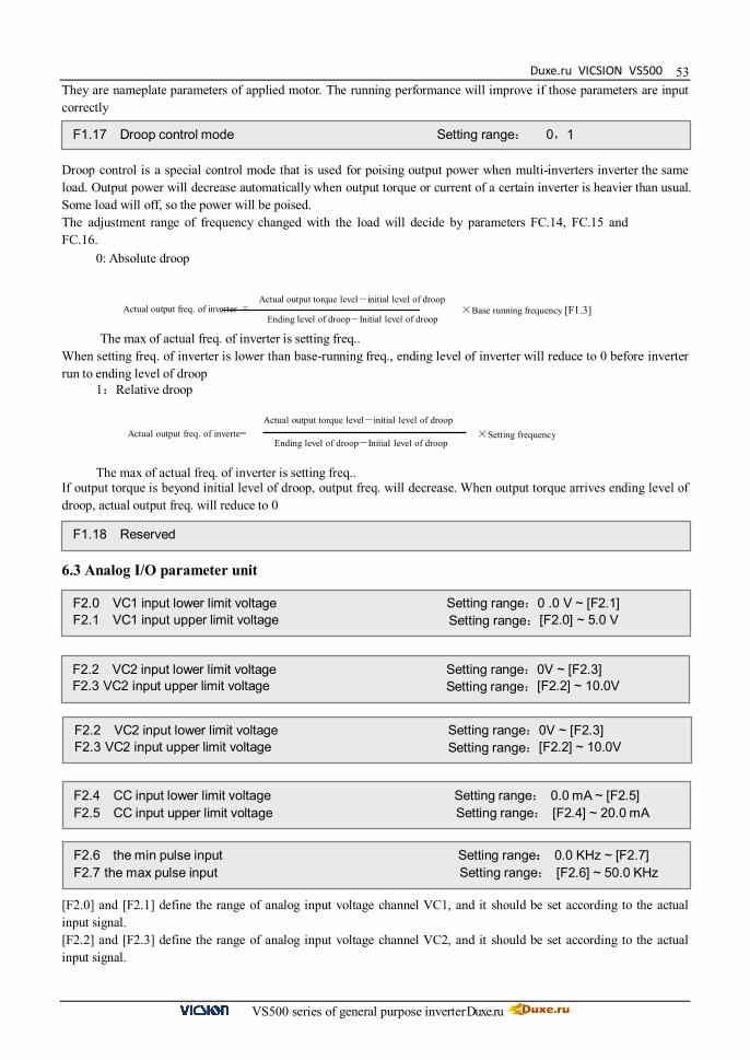
Duxe.ru VICSION VS500
VS500 series of general purpose inverter Duxe.ru
53They are nameplate parameters of applied motor. The running performance will improve if those parameters are input correctly Droop control is a special control mode that is used for poising output power when multi-inverters inverter the same load. Output power will decrease automatically when output torque or current of a certain inverter is heavier than usual. Some load will off, so the power will be poised. The adjustment range of frequency changed with the load will decide by parameters FC.14, FC.15 and FC.16.
0: Absolute droop
The max of actual freq. of inverter is setting freq.. When setting freq. of inverter is lower than base-running freq., ending level of inverter will reduce to 0 before inverter run to ending level of droop
1:Relative droop
The max of actual freq. of inverter is setting freq.. If output torque is beyond initial level of droop, output freq. will decrease. When output torque arrives ending level of droop, actual output freq. will reduce to 0 6.3 Analog I/O parameter unit [F2.0] and [F2.1] define the range of analog input voltage channel VC1, and it should be set according to the actual input signal. [F2.2] and [F2.3] define the range of analog input voltage channel VC2, and it should be set according to the actual input signal.
F1.17 Droop control mode Setting range: 0,1
Actual output torque level-initial level of droop Ending level of droop-Initial level of droop ×Base running frequency [F1.3] Actual output freq. of inverter =
Actual output freq. of inverte= Actual output torque level-initial level of droop
Ending level of droop-Initial level of droop ×Setting frequency
F1.18 Reserved
F2.0 VC1 input lower limit voltage Setting range:0 .0 V ~ [F2.1] F2.1 VC1 input upper limit voltage Setting range:[F2.0] ~ 5.0 V
F2.2 VC2 input lower limit voltage Setting range:0V ~ [F2.3] F2.3 VC2 input upper limit voltage Setting range:[F2.2] ~ 10.0V
F2.2 VC2 input lower limit voltage Setting range:0V ~ [F2.3] F2.3 VC2 input upper limit voltage Setting range:[F2.2] ~ 10.0V
F2.4 CC input lower limit voltage Setting range: 0.0 mA ~ [F2.5] F2.5 CC input upper limit voltage Setting range: [F2.4] ~ 20.0 mA
F2.6 the min pulse input Setting range:: 0.0 KHz ~ [F2.7] F2.7 the max pulse input Setting range: [F2.6] ~ 50.0 KHz

VICSION VS500
VS500 series of general purpose inverter Duxe.ru
54
Freq
Analog value Input lower limit
[F2.9]
[F2.8]
Output freq
Analog value Input upper limi
Positive character
Freq
[F2.9]
[F2.8]
Output freq
Negative character
Analog value Input lower limit
Analog value Input upper limi
[F2.4] and [F2.5] define the range of analog input current channel CC, and it should be set according to the actual input signal. [F2.6] and [F2.7] define the freq. range of external pulse signal They define the Corresponding relation between analog input (pulse input) and setting frequency. Shown as fig.6-10
It is used for selecting input character of external analog value or pulse value. The first part of LED (form right to left): It defines character of voltage signal analog input VC1.
0: positive character 1:Negative character The second part of LED (form right to left): It defines character of voltage signal analog input VC2.
0: positive character 1:Negative character The third part of LED (form right to left): It defines character of current signal analog input CC.
0: positive character 1:Negative character The fourth part of LED (form right to left): It defines character of pulse signal analog input PLS.
0: positive character 1:Negative character The corresponding relation is shown as fig.6-10 between input signal and setting freq Setting freq. set by external analog input will be filtered to eliminate fluctuation. Time constant of filtering have to appropriate set according to fluctuate of external input signal. The parameter is valid only when the frequency input channel F0.1 is set as 8 The setting frequency of the inverter is determined by the linear combination of multiple frequency input channels, and please see the following table for the combination modes of setting. Frequency output of inverter jointly controlled by multiple channels can be realized through the combination setting.
Setting
Value Combination setting mode Setting
Value Combination setting mode
0 External voltageVC1 + External current CC 1 External voltageVC1 - External current CC
2 External voltageVC2 + External current CC 3 External voltageVC2 - External current CC
4 External voltageVC1 + External voltageVC2 5 External voltageVC1 - External voltage VC2
6 External voltageVC1 + pulse setting 7 External voltageVC1 - pulse setting
F2.8 frequency with the min setting Setting range:: 0.0Hz ~ [F2.9] F2.9 frequency with the max setting Setting range: [F2.8] ~ 600.0Hz
F2.10 Character selection of input channel Setting channel: 0000 ~ 1111
Fig.6-10 Corresponding relation between analog input and setting freq
F2.11 External freq. set time constant of filtering Setting range: 0.01 ~ 1.00s
F2.12 Combination setting mode Setting range:0 ~ 29

Duxe.ru VICSION VS500
VS500 series of general purpose inverter Duxe.ru
55Setting
Value Combination setting mode Setting
Value Combination setting mode
8 External voltageVC2+ External current CC+ pulse setting 9 External voltageVC2+ External current CC- pulse
setting
10 External voltageVC1 + panel setting + pulse setting 11 External voltageVC1+ panel setting - pulse setting
12 External voltage1 + panel setting + digital setting 13 External voltage1 - panel setting + digital setting
14 External voltage2 + panel setting + digital setting 15 External voltage2 - panel setting + digital setting
16 External current + panel setting + digital setting 17 External current - panel setting + digital setting
18 Serials interface setting + External voltage1 19 Serials interface setting - External voltage1
20 Serials interface setting + External current + pulse setting 21 Serials interface setting - External current + pulse
setting
22 Serials interface setting + External voltage1 + panel setting 23 Serials interface setting + External voltage2 - panel
setting
24 External voltage2 + External current + pane setting 25 External voltage2+ External current - panel setting + digital setting
26 The max of external voltage1 and external voltage2 27 The max among External voltage1, External voltage2 and
28 Nonzero valid of External voltage1and External voltage2 29 Nonzero valid External voltage1, External voltage2
and External current CC
30 External voltage 1+external terminal vp/dw
It defines meaning of AO1、AO2.
The first part of LED: it defines the meaning of analog output terminal AO1. The second part of LED: it defines the meaning of analog output terminal AO2.
0:Output freq Amplitude accumulation of AO1 and AO2 are in direct ratio to the output frequency. F2.15 and F2.17 are corresponding to the upper limit freq. 1:Output current Amplitude accumulation of AO1 and AO2 are in direct ratio to the output current. F2.15 and F2.17 are twice rated current of inverter. 2:Output voltage Amplitude accumulation of AO1 and AO2 are in direct ratio to the output voltage. F2.15 and F2.17 are corresponding to [F1.4] and [F1.14]. 3:Rotate speed of applied motor Amplitude accumulation of AO1 and AO2 are in direct ratio to the motor rotate speed of inverter. F2.15 and F2.17 is corresponding rotate speed that is corresponded the upper limit freq. 4:PID setting Amplitude accumulation of AO1 and AO2 are in direct ratio to the setting value of PID. F2.15 and F2.17 are corresponding to feedback of 10.00. 5:PID feedback Amplitude accumulation of AO1 and AO2 are in direct ratio to the PID feedback. F2.15 and F2.17 are corresponding to feedback of 10.00.
The third and fourth part of LED: Reserved.
F2.13 Analog output selection Setting range: 0000 ~ 0055
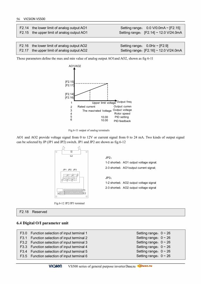
VICSION VS500
VS500 series of general purpose inverter Duxe.ru
56
[F2.15]
AO1/AO2
Output freq Upper limit voltage
The max/rated Voltage Rotor speed PID setting
PID feedback
1 2 3 4 5 6
10.00 10.00
[F2.17]
[F2.14] [F2.16]
Rated current Output curren Output voltage
Those parameters define the max and min value of analog output AO1and AO2, shown as fig 6-11 AO1 and AO2 provide voltage signal from 0 to 12V or current signal from 0 to 24 mA. Two kinds of output signal can be selected by JP (JP1 and JP2) switch. JP1 and JP2 are shown as fig.6-12 6.4 Digital O/I parameter unit
F2.14 the lower limit of analog output AO1 Setting range: 0.0 V/0.0mA ~ [F2.15] F2.15 the upper limit of analog output AO1 Setting range: [F2.14] ~ 12.0 V/24.0mA
F2.16 the lower limit of analog output AO2 Setting range:: 0.0Hz ~ [F2.9] F2.17 the upper limit of analog output AO2 Setting range: [F2.16] ~ 12.0 V/24.0mA
Fig.6-11 output of analog terminals
+5V
+10V
JP1 JP2
VO2
VO1
JP3
CO
1
CO
2
JP2: 1-2 shorted:AO1 output voltage signal;
2-3 shorted:AO1output current signal;
JP3:
1-2 shorted:AO2 output voltage signal
2-3 shorted:AO2 output voltage signal
Fig.6-12 JP2/JP3 terminal
F2.18 Reserved
F3.0 Function selection of input terminal 1 Setting range:0 ~ 26 F3.1 Function selection of input terminal 2 Setting range:0 ~ 26 F3.2 Function selection of input terminal 3 Setting range:0 ~ 26 F3.3 Function selection of input terminal 4 Setting range:0 ~ 26 F3.4 Function selection of input terminal 5 Setting range:0 ~ 26 F3.5 Function selection of input terminal 6 Setting range:0 ~ 26
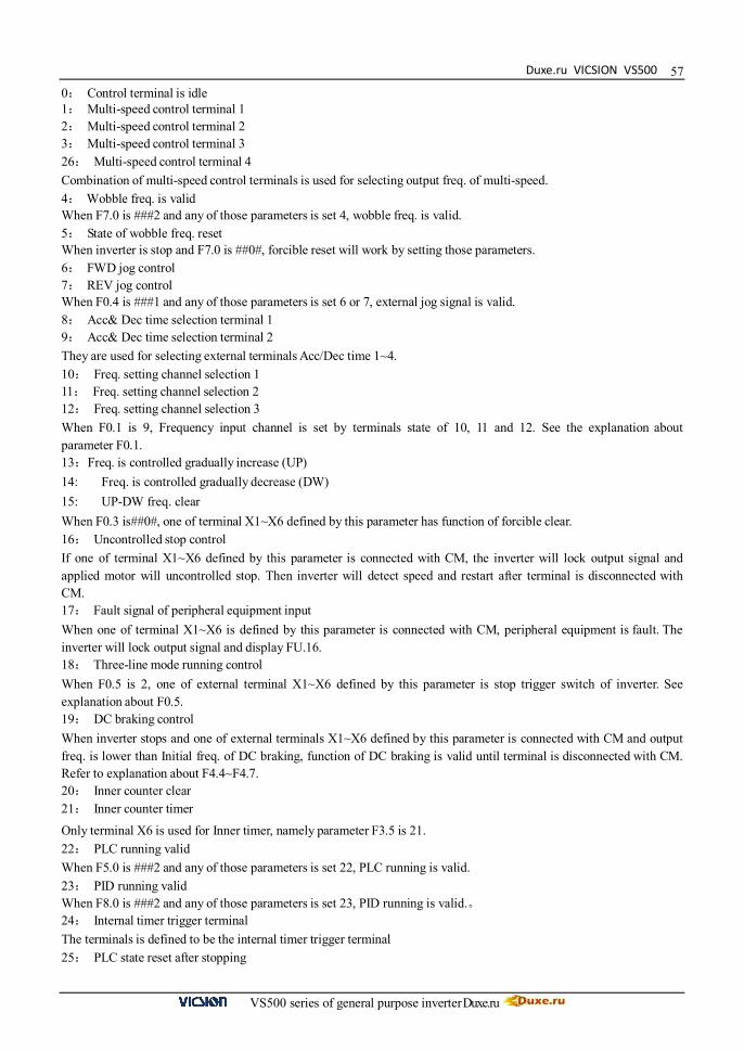
Duxe.ru VICSION VS500
VS500 series of general purpose inverter Duxe.ru
570: Control terminal is idle 1: Multi-speed control terminal 1 2: Multi-speed control terminal 2 3: Multi-speed control terminal 3 26: Multi-speed control terminal 4 Combination of multi-speed control terminals is used for selecting output freq. of multi-speed. 4: Wobble freq. is valid When F7.0 is ###2 and any of those parameters is set 4, wobble freq. is valid. 5: State of wobble freq. reset When inverter is stop and F7.0 is ##0#, forcible reset will work by setting those parameters. 6: FWD jog control 7: REV jog control When F0.4 is ###1 and any of those parameters is set 6 or 7, external jog signal is valid. 8: Acc& Dec time selection terminal 1 9: Acc& Dec time selection terminal 2 They are used for selecting external terminals Acc/Dec time 1~4. 10: Freq. setting channel selection 1 11: Freq. setting channel selection 2 12: Freq. setting channel selection 3 When F0.1 is 9, Frequency input channel is set by terminals state of 10, 11 and 12. See the explanation about parameter F0.1. 13:Freq. is controlled gradually increase (UP) 14: Freq. is controlled gradually decrease (DW) 15: UP-DW freq. clear When F0.3 is##0#, one of terminal X1~X6 defined by this parameter has function of forcible clear. 16: Uncontrolled stop control If one of terminal X1~X6 defined by this parameter is connected with CM, the inverter will lock output signal and applied motor will uncontrolled stop. Then inverter will detect speed and restart after terminal is disconnected with CM. 17: Fault signal of peripheral equipment input When one of terminal X1~X6 is defined by this parameter is connected with CM, peripheral equipment is fault. The inverter will lock output signal and display FU.16. 18: Three-line mode running control When F0.5 is 2, one of external terminal X1~X6 defined by this parameter is stop trigger switch of inverter. See explanation about F0.5. 19: DC braking control When inverter stops and one of external terminals X1~X6 defined by this parameter is connected with CM and output freq. is lower than Initial freq. of DC braking, function of DC braking is valid until terminal is disconnected with CM. Refer to explanation about F4.4~F4.7. 20: Inner counter clear 21: Inner counter timer Only terminal X6 is used for Inner timer, namely parameter F3.5 is 21. 22: PLC running valid When F5.0 is ###2 and any of those parameters is set 22, PLC running is valid. 23: PID running valid When F8.0 is ###2 and any of those parameters is set 23, PID running is valid.。 24: Internal timer trigger terminal The terminals is defined to be the internal timer trigger terminal 25: PLC state reset after stopping
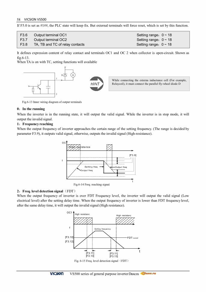
VICSION VS500
VS500 series of general purpose inverter Duxe.ru
58If F5.0 is set as #1##, the PLC state will keep fix. But external terminals will force reset, which is set by this function. It defines expression content of relay contact and terminals OC1 and OC 2 when collector is open-circuit. Shown as fig.6-13. When TA is on with TC, setting functions will available 0:In the running When the inverter is in the running state, it will output the valid signal. While the inverter is in stop mode, it will output the invalid signal. 1:Frequency reaching When the output frequency of inverter approaches the certain range of the setting frequency. (The range is decided by parameter F3.9), it outputs valid signal, otherwise, outputs the invalid signal (High-resistance). 2:Freq. level detection signal(FDT) When the output frequency of inverter is over FDT Frequency level, the inverter will output the valid signal (Low electrical level) after the setting delay time. When the output frequency of inverter is lower than FDT frequency level, after the same delay time, it will output the invalid signal (High resistance).
F3.6 Output terminal OC1 Setting range:0 ~ 18 F3.7 Output terminal OC2 Setting range:0 ~ 18 F3.8 TA, TB and TC of relay contacts Setting range:0 ~ 18
R 1
2
D
While connecting the externa inductance cell (For example, Relaycoil), it must connect the parallel fly-wheel diode D
Fig.6-13 Inner wiring diagram of output terminals
OC
f
H ig h re s ista nce
[F3.9]
t
Ou tpu t freq
Se ttin g freq Output freq
Fig.6-14 Freq. reaching signal
High resistanc High resistanc
Setting frequency
OC1
t [F3.11] [F3.13]
[F3.11] [F3.13]
[F3.10]
[F3.12] FDT Level
f
Fig. 6-15 Freq. level detection signal(FDT)

Duxe.ru VICSION VS500
VS500 series of general purpose inverter Duxe.ru
593:Over-loading alarm When the output current of inverter is over the over-loading alarm level, it will output the valid signal (Low level) after the setting alarm delay time. When the output current is lower than the over-loading alarm level, it will output the invalid signal (High resistance) after the same delay time. 4:External fault halt When the external fault input signal is valid and it will lead to stop-machine, the terminal will output the valid signal (Low level); otherwise it will output the invalid signal (High resistance). 5:Output frequency reaches the upper-limit When the output frequency reaches the upper-limit frequency, the terminal will output the valid signal (Low level). Otherwise, it will output the invalid signal (High resistance). 6:Output frequency reaches the lower-limit When the output frequency reaches the lower-limit frequency, the terminal will output the valid signal (Low level). Otherwise, it will output the invalid signal (High resistance) 7: Running in zero speed Running instruction is valid and output freq. is 0, if inverter is input freq., the terminal will output the valid signal (Low electrical level). If inverter is not input freq., the terminal will output the invalid signal (High resistance). 8:Internal timer reaches the setting time When the internal timer reaches the setting time, the terminal will output the valid pulse signal of 0.5 Sec pulse widths. (Low electrical level) 9: PLC stage is end of run When simple PLC is valid and current stage is end, this port will output pulse signal with 0.5s pulse width. 10:PLC periodic is end of run When simple PLC is valid and current period is end, this port will output pulse signal with 0.5s pulse width. 11:Internal timer arrive regular time If the internal timer arrive regular time, the corresponding port will output 0.5s width pulse signal. 12:Setting value of counter arrives See the explanation about parameter F6.3 13:Designated value of counter arrives See the explanation about parameter F6.4. 14:Deceleration running 15:Reserved 16:Inverter fault When inverter is running with fault, it will output available signal (low level). 17:Restrictions on wobble freq. of the upper and lower limit freq. When parameters setting about wobble freq. result in that running freq. is beyond the upper and lower limit freq., this port will output available signal (lower lever). Generally, this port output high resistance. 18:Reserved
O u tp u t c u rr en t
t [ F 3 .1 5 ]
O C
[F 3 .1 5 ]
A l a r m l e v e l
[ F 3 .1 4 ]
H i g h r e s is t a n c e H i g h re s is t a n c e
Fig.6-16 Over-load alarm
F3. 9 Frequency reach the checkout amplitude Setting range:0.0 ~ 20.00Hz

VICSION VS500
VS500 series of general purpose inverter Duxe.ru
60
t
f
Free s to pt
D ec e le ra te s top w ith n o D C braking
S ett ing f req
[F4.1] [F4.2]
Start
If output freq. of inverter is within setting value that is set by F3.9, selected terminal will output valid signal. Shown as fig.6-15 The parameter is used for setting the frequency detection level. When output frequency is higher than the setting value of FDT, after the setting delay time, terminals will output the valid signal, shown as fig.6-15. Parameters F3.10 and F3.11 are used for setting FDT of OC1, parameters F3.12 and F3.13 are used for setting FDT of OC2 If output freq. beyond the setting value set by parameter F3.14, after the setting delay time set by parameter F3.15, terminals output valid signal, shown as fig.6-16 6.5 Auxiliary running parameter unit Those parameters are used for defining characteristic with relation to start mode, shown as fig6-17. The explanation of F4.0 is shown as follows. 0: Routine mode It is fit for mostly load, which have not special demand. 1:Detect speed and restart It is fit for fault reset and restart occasion, or, power off and restart occasion. Inverter will judge automatically running speed and direction of motor. Motor, which have not stop, will start up directly according to detect result. Start frequency:It is fit for system, which are big inertia, heavy load and high start torque 0: Decelerate mode Inverter will gradually decrease output freq. to 0 according to Dec time when stopping. 1: Uncontrolled stop
F3.10 FDT setting 1 Setting range:0.0 ~ upper limit freq. F3.11 FDT output delay time 1 Setting range:0.0 ~ 200.0 s F3.12 FDT setting 2 Setting range:0.0 ~ Setting range F3.13 FDT output delay time 2 Setting range:0.0 ~ 200.0 s
F3.14 Overload alarm level Setting range:50 ~ 200(%)
F3.15 Overload alarm delay time Setting range:0.0 ~ 20.0s
F3.16 Reserved
F4.0 Start mode Setting range:0~1 F4.1 Start frequency Setting range:0.0~10.00Hz F4.2 Start frequency duration Setting range:0.0~20.0s
Fig6-17 Start and stop freq output curve
F4.3 Stop mode Setting range:0 ~ 1
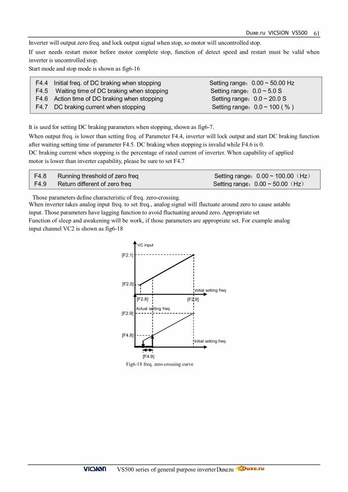
Duxe.ru VICSION VS500
VS500 series of general purpose inverter Duxe.ru
61
[F2.0]
VC input
[F2.9]
initial setting freq [F2.8]
[F2.1]
[F2.9]
[F4.8]
[F4.9]
initial setting freq
Actual setting freq
Inverter will output zero freq. and lock output signal when stop, so motor will uncontrolled stop. If user needs restart motor before motor complete stop, function of detect speed and restart must be valid when inverter is uncontrolled stop. Start mode and stop mode is shown as fig6-16 It is used for setting DC braking parameters when stopping, shown as fig6-7. When output freq. is lower than setting freq. of Parameter F4.4, inverter will lock output and start DC braking function after waiting setting time of parameter F4.5. DC braking when stopping is invalid while F4.6 is 0. DC braking current when stopping is the percentage of rated current of inverter. When capability of applied motor is lower than inverter capability, please be sure to set F4.7
Those parameters define characteristic of freq. zero-crossing. When inverter takes analog input freq. to set freq., analog signal will fluctuate around zero to cause astable input. Those parameters have lagging function to avoid fluctuating around zero. Appropriate set Function of sleep and awakening will be work, if those parameters are appropriate set. For example analog input channel VC2 is shown as fig6-18
F4.4 Initial freq. of DC braking when stopping Setting range:0.00 ~ 50.00 Hz F4.5 Waiting time of DC braking when stopping Setting range:0.0 ~ 5.0 S F4.6 Action time of DC braking when stopping Setting range:0.0 ~ 20.0 S F4.7 DC braking current when stopping Setting range:0.0 ~ 100 ( % )
F4.8 Running threshold of zero freq Setting range:0.00 ~ 100.00(Hz)F4.9 Return different of zero freq Setting range:0.00 ~ 50.00(Hz)
Fig6-18 freq. zero-crossing curve
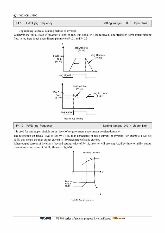
VICSION VS500
VS500 series of general purpose inverter Duxe.ru
62
t
FWD Jog Freq. [F4.10]
f Jog Acc time
[F4.21]
f
t Jog signal
FWD Jog Freq. [F4.10]
Jog Dec time [F4.22]
Jog Dec time [F4.22]
Jog Acc time [F4.21]
Jog signal
t
Braking torque level
f
t
t
t
Modified Dec time
Jog running is special running method of inverter. Whatever the initial state of inverter is stop or run, jog signal will be received. The transition form initial running freq. to jog freq. is ac8 according to parameters F4.21 and F4.22 It is used for setting permissible output level of torque current under motor acceleration state. The restriction on torque level is set by F4.11. It is percentage of rated current of inverter. For example, F4.11 set 150% that means the max output current is 150 percentage of rated current. When output current of inverter is beyond setting value of F4.11, inverter will prolong Acc/Dec time to inhibit output current in setting value of F4.11. Shown as fig6-20.
F4.10 FWD jog frequency Setting range:0.0 ~ Upper limit
Fig6-19 Jog running
F4.10 FWD jog frequency Setting range:0.0 ~ Upper limit
Fig6-20 Acc torque level
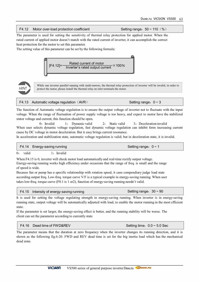
Duxe.ru VICSION VS500
VS500 series of general purpose inverter Duxe.ru
63 The parameter is used for setting the sensitivity of thermal relay protection for applied motor. When the rated current of applied motor doesn’t match with the rated current of inverter, it can accomplish the correct heat protection for the motor to set this parameter. The setting value of this parameter can be set by the following formula:
The function of Automatic voltage regulation is to ensure the output voltage of inverter not to fluctuate with the input voltage. When the range of fluctuation of power supply voltage is too heavy, and expect to motor have the stabilized stator voltage and current, this function should be open.
0:Invalid 1: Dynamic valid 2: Static valid 3:Deceleration invalid When user selects dynamic voltage regulation, fast dynamic voltage regulation can inhibit form increasing current cause by DC voltage in motor deceleration. But it easy brings current resonance. In acceleration and stabilization state, automatic voltage regulation is valid; but in deceleration state, it is invalid. 0: valid 1:Invalid
When F4.15 is 0, inverter will check motor load automatically and real-time rectify output voltage. Energy-saving running works high efficiency under occasions that the range of freq. is small and the range of speed is wide. Because fan or pump has a specific relationship with rotation speed, it cans compendiary judge load state according output freq. Low-freq. torque curve V/F is a typical example in energy-saving running. When user takes low-freq. torque curve (F0.1 is 1 or2), function of energy-saving running needn’t valid. It is used for setting the voltage regulating strength in energy-saving running. When inverter is in energy-saving running state, output voltage will be automatically adjusted with load, to enable the motor running in the most efficient state. If the parameter is set larger, the energy-saving effect is better, and the running stability will be worse. The client can set the parameter according to currently state The parameter means that the duration at zero frequency when the inverter changes its running direction, and it is shown as the following fig.6-20. FWD and REV dead time is set for the big inertia load which has the mechanical dead zone.
F4.12 Motor over-load protection coefficient Setting range:50 ~ 110(%)
[F4.12]= ×100% Rated current of motor Inverter’s rated output current
While one inverter parallel running with multi-motors, the thermal relay protection of inverter will be invalid, in order to protect the motor, please install the thermal relay on inlet terminals the motor.
F4.13 Automatic voltage regulation(AVR) Setting range:0 ~ 3
F4.14 Energy-saving running Setting range:0 ~ 1
F4.15 Intensity of energy-saving running Setting range:30 ~ 90
F4.16 Dead time of FWD&REV Setting time:0.0 ~ 5.0 Sec

VICSION VS500
VS500 series of general purpose inverter Duxe.ru
64
Jog frequency has the highest priority. In any state, as long as Jog instruction is input, the inverter will transit to run at Jog frequency according to the setting Acc and Dec time. It defines rate that terminals UP/DW modify setting freq. Speed of F4.23 isn’t controlled by Acc/Dec time Those parameters are valid for inverter with the inner brake unit. And they define the action parameter of inner brake unit. When inner DC voltage of inverter is higher than the start voltage of dynamic braking, the inner brake unit will act. If inverter connects external brake resistance, DC energy of inverter will be release by it to decline DC voltage. When DC voltage declines to the certain value ([F4.24]-50V), inner brake unit of inverter will be off, shown as Fig.6-23. Brake unit action ratio is used for defining the voltage on brake resistor, and the voltage on brake unit is Voltage PWP. Duty cycle equals break action ratio. The ratio is larger, and the energy is consumed more quickly, at the same time, the power of brake resistor is bigger. User can set parameter according to the resistance and power of resistor and actual brake effect.
t
[F4.16]
Output frequency
Fig.6-21 Dead zone between FWD and REV
F4.17 Acceleration time 2 Setting range:0.1 ~ 6000 Sec F4.18 Deceleration time 2 Setting range:0.1 ~ 6000 Sec F4.19 Acceleration time 3 Setting range:0.1 ~ 6000 Sec F4.20 Deceleration time 3 Setting range:0.1 ~ 6000 Sec F4.21 Acc time 4/Jog Acc time Setting range:0.1 ~ 6000Sec F4.22 Dec time 5/Jog Dec time Setting range:0.1 ~ 6000Sec
f
t Acc/Dec terminal 1
Acc/Dec terminal 2 Acc/Dec time1
Acc/Dec Time2
Acc/Dec Time3
Acc/Dec Time4
Running instrum ent
Fig.6-22 Acc/Dec time selection
F4.23 Modified rated of UP/DW terminals Setting range:0.01 ~ 100.00 (Hz/Sec)
F4.24 Start voltage of dynamic braking Setting range:600 ~ 750 V F4.25 Action ratio of dynamic braking Setting range:10 ~ 100(%)
Brake unit acts
t
DC Voltage
[F4.24]
[F4.24]-50V
Fig.6-23 dynamic braking
Duxe.ru VICSION VS500
VS500 series of general purpose inverter Duxe.ru
65 Parameter F4.26 The first part of LED 0:Invalid 1: Valid When restart after power down setting is invalid, the inverter will clear automatically all running command and run according to new command after power on. When restart after power down setting is valid, the inverter will save all running command and run according to the save command after power on. Please make sure that other equipments in system are ready before using function of restart after power Down.
The second part of LED: Applied motor is still running when user select restart. Here, users have to select function of checking speed and restarting. The third and fourth part of LED: reserved. 6.6 Multi-speed running parameter unit
F4.26 Restart after power down setting Setting range:0000 ~ 0011 F4.27 waiting time of restart after power down Setting range:0.0 ~ 10.0s
F4.28 REV jog frequency Setting range:0.0 ~ Upper limit
F5.0 Multi-speed running mode Setting range:0000 ~ 1252
F5.1 Multi-speed frequency 1 Setting range:0.0 ~ the upper limit freq F5.2 Multi-speed frequency 2 Setting range:0.0 ~ the upper limit freq F5.3 Multi-speed frequency 3 Setting range:0.0 ~ the upper limit freq F5.4 Multi-speed frequency4 Setting range:0.0 ~ the upper limit freq F5.5 Multi-speed frequency 5 Setting range:0.0 ~ the upper limit freq F5.6 Multi-speed frequency 6 Setting range:0.0 ~ the upper limit freq F5.7 Multi-speed frequency 7 Setting range:0.0 ~ the upper limit freq F5.8 Multi-speed frequency8 Setting range:0.0 ~ the upper limit freq F5.9 Multi-speed frequency 9 Setting range:0.0 ~ the upper limit freq F5.10 Multi-speed frequency 10 Setting range:0.0 ~ the upper limit freq F5.11 Multi-speed frequency 11 Setting range:0.0 ~ the upper limit freq F5.12 Multi-speed frequency12 Setting range:0.0 ~ the upper limit freq F5.13 Multi-speed frequency 13 Setting range:0.0 ~ the upper limit freq F5.14 Multi-speed frequency 14 Setting range:0.0 ~ the upper limit freq F5.15 Multi-speed frequency 15 Setting range:0.0 ~ the upper limit freq
F5.16 Running time of Multi-speed1 Setting range:0.0 ~ 6000s F5.17 Running time of Multi-speed2 Setting range:0.0 ~ 6000s F5.18 Running time of Multi-speed3 Setting range:0.0 ~ 6000s F5.19 Running time of Multi-speed4 Setting range:0.0 ~ 6000s F5.20 Running time of Multi-speed5 Setting range:0.0 ~ 6000s F5.21 Running time of Multi-speed6 Setting range:0.0 ~ 6000s F5.22 Running time of Multi-speed7 Setting range:0.0 ~ 6000s F5.23 Running time of Multi-speed8 Setting range:0.0 ~ 6000s

VICSION VS500
VS500 series of general purpose inverter Duxe.ru
66
Parameter F5.0 is multi-speed running mode. It is used for setting basic characteristic of multi-speed running.
The first part of LED(form right to left):Simple PLC selection 0:Simple PLC is invalid. 1:Simple PLC is valid. If priority of freq. channel is permit after starting, inverter will run at simple PLC state 2:Simple PLC is conditional valid. If external X1~X6 terminals is valid (F3.0~F3.5 is set as 22), inverter will run at simple PLC state. Priority of freq. channel is shown as following table:
Priority grade Priority Setting freq
High
Low
1 JOG freq.
2 Wobble freq. running
3 PID output
4 PLC multi-speed freq
5 External terminals select multi-speed freq
6 Freq. setting channel selection(Parameter [F0.1] )
The second part of LED:Simple PLC running mode selection 0:Single loop mode The inverter will run in setting freq of the first stage and in turn output freq. of each stage according to setting running time. If setting running time of a certain stage is 0, the inverter will skip this stage. When a cycle operation is end of run, inverter will stop input until user input available running instrument to restart a next cycle. 1:Single loop and stop mode Its function has an analogy with single loop mode. The difference is that output freq. is be reduced to 0 within the given decelerate time after a certain stage is end of run and inverter will run next stage. 2:Continuous loop mode Inverter will run eight stages in turn. If the eighth stage is end of run, the inverter will run the next cycle form the first stage. 3:Continuous loop and stop mode Its function has an analogy with Continuous loop mode. The difference is that output freq. is be reduced to 0 within the given decelerate time after a certain stage is end of run and inverter will run next stage. 4:Keep the end value Its function has an analogy with single loop mode. The difference is that inverter will run in the last stage with non-zero speed. 5:Keep the end value and stop mode Its function has an analogy with keep the end value. The difference is that inverter will reduce the output freq. to 0 after arriving setting value of Acc time after a certain stage is end of run and, then inverter will run the next stage
The third part of LED 0:Restart from the first stage freq. When inverter stop, caused by fault or receiving stop instrument in PLC running, it will clear current running state and restart form the first stage freq. 1:Restart from running freq., which is saved before the running is breaking. When inverter stop, caused by fault or receiving stop instrument in PLC running, inverter will restart from running time and freq. that is saved before the running is breaking.
F5.24 Running direction of PLC multi-speed Setting range:0000 ~ 1111 F5.25 Running direction of PLC multi-speed Setting range:0000 ~ 1111
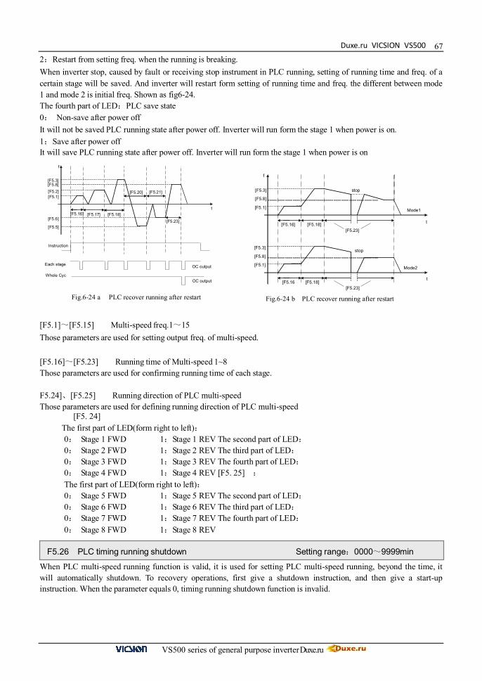
Duxe.ru VICSION VS500
VS500 series of general purpose inverter Duxe.ru
67
Instruction
Each stage
Whole Cyc
[F5.3]
[F5.2] [F5.1]
[F5.6]
[F5.5]
[F5.8]
[F5.16] [F5.17] [F5.18]
[F5.20] [F5.21]
[F5.23]
f
t
OC output
OC output
2:Restart from setting freq. when the running is breaking. When inverter stop, caused by fault or receiving stop instrument in PLC running, setting of running time and freq. of a certain stage will be saved. And inverter will restart form setting of running time and freq. the different between mode 1 and mode 2 is initial freq. Shown as fig6-24. The fourth part of LED:PLC save state 0: Non-save after power off It will not be saved PLC running state after power off. Inverter will run form the stage 1 when power is on. 1:Save after power off It will save PLC running state after power off. Inverter will run form the stage 1 when power is on
[F5.1]~[F5.15] Multi-speed freq.1~15 Those parameters are used for setting output freq. of multi-speed. [F5.16]~[F5.23] Running time of Multi-speed 1~8 Those parameters are used for confirming running time of each stage. F5.24]、[F5.25] Running direction of PLC multi-speed Those parameters are used for defining running direction of PLC multi-speed
[F5. 24] The first part of LED(form right to left): 0: Stage 1 FWD 1:Stage 1 REV The second part of LED: 0: Stage 2 FWD 1:Stage 2 REV The third part of LED: 0: Stage 3 FWD 1:Stage 3 REV The fourth part of LED: 0: Stage 4 FWD 1:Stage 4 REV [F5. 25] : The first part of LED(form right to left): 0: Stage 5 FWD 1:Stage 5 REV The second part of LED: 0: Stage 6 FWD 1:Stage 6 REV The third part of LED: 0: Stage 7 FWD 1:Stage 7 REV The fourth part of LED: 0: Stage 8 FWD 1:Stage 8 REV
When PLC multi-speed running function is valid, it is used for setting PLC multi-speed running, beyond the time, it will automatically shutdown. To recovery operations, first give a shutdown instruction, and then give a start-up instruction. When the parameter equals 0, timing running shutdown function is invalid.
[F5.3]
[F5.1]
[F5.8]
[F5.16] [F5.18] [F5.23]
f
t
stop
[F5.3]
[F5.1]
[F5.8]
[F5.16 [F5.18]
stop
[F5.23]
Mode1
Mode2
t
Fig.6-24 a PLC recover running after restart Fig.6-24 b PLC recover running after restart
F5.26 PLC timing running shutdown Setting range:0000~9999min

VICSION VS500
VS500 series of general purpose inverter Duxe.ru
68
6.7 Advanced running parameter unit It is used for setting the internal timer. The internal timer is triggering start-upped by external terminals X1~ X6, external terminals X1~X6 should be set as 24(explained by parameters F3.0~F3.5). Internal timer arrives the regular time, OC1、OC2 or TA,TB,TC will output 0.5s width pulse (set by F3.6~ F3.8) The function can realize the timing operation shutdown. F6.1 is used for resetting some faults and run again F6.2 defines interval time between fault starting and fault recovery. If inverter can’t recover in setting value of F6.1, it will output fault signal. Inverter will check speed and restart.
The parameter defines the counting action of internal counter, and the clock terminals of counter are selected by parameter F1.6. The counting value of counter for the external clock reaches the value appointed by parameter F3.5, and the corresponding Terminal OC outputs a valid signal of same width with the external clock cycle. When the counting value of counter for external clock reached the value appointed by Parameter F6.3, the corresponding Terminal OC will output the valid signal, Go on counting to the value provided by parameter F6.4, which will lead to reset and the output valid signal will be withdrawn. The clock cycle of counter should be over 5ms and the min width should be 2ms It is used for avoiding resonance point of mechanical load. Shown as fig. 6-26
F6.0 interna timer Setting range:0.1 ~ 6000.0 Sec
F6.1 Fault self-recovery time Setting range:0 ~ 2 F6.2 Interval time of fault self-recovery Setting range:0.2 ~ 20.0s
Inverter can’t self-recovery about overheat or overload protect
F6.3 Final value setup of internal counter Setting range:1 ~ 60000 F6.4 Internal timer setup Setting range:1 ~ 60000
[F6.3]
[F6.4]
OC
Pluse
OC
Fig.6-25 Internal counter function
F6.5 Skip freq. 1 Setting range::0.0 ~ upper frequency F6.6 Amplitude accumulation of Skip freq. 1 Setting range:0.0 ~ 5.00Hz F6.7 Skip freq.2 Setting range:0.0 ~ upper frequency F6.8 Amplitude accumulation of Skip freq. Setting range:0.0 ~ 5.00Hz

Duxe.ru VICSION VS500
VS500 series of general purpose inverter Duxe.ru
69 This parameter is used for confirming the display value of running linear speed and setting linear speed, and displaying other value being positive ratio with the output frequency. It is used for rectifying the display value of rotator speed. This parameter is used for confirming display content of operation panel in state monitor mode. It is used for getting check code to query or modify parameters. It is used for modifying inverter’s parameters to manufacture setting. 0:Parameter initialization is off. 1:Parameter initialization is on. Parameter F0~F9 return to manufacture setting. The following parameters can’t be initialized:
Amplitude accumulation of Skip freq. 2
Amplitude accumulation ofSkip freq. 1
Skip freq 2
Adjusted setting freq
Skip freq 1
Fig.6-26 Skip freq
F6.9 Linear speed coefficient setting Setting range:0.01 ~ 100.0
Running linear velocity(d.10)= [F6.9] × output frequency (d.0) Setting linear velocity(d.11)= [F6.9] × Setting frequency (d.6)
F6.10 close-loop analog coefficient setting Setting range:0.01 ~ 100.0
PID feedback value(d.9)= [F6.10] × actual feedback value PID setting value(d.8)= [F6.10] × setting value
F6.11 rotator speed coefficient setting Setting range: 0.01 ~ 10.00
rotator speed(d.3)= [F6.11] × actual output rotator speed
F6.12 Monitor item selection 1 / Main display Setting range:0 ~ 11 F6.13 Monitor item selection 2 / Auxiliary display Setting range:0 ~ 19
F6.14 Query or modify parameters Setting range : 0 ~ 9999
F6.15 parameter initialization Setting range:0 ~ 3
VICSION VS500
VS500 series of general purpose inverter Duxe.ru
70
[F0.0]:Reserved [F0.1]:Frequency input channel / mode selection [F0.4]:Operation channel selection [F6.17]:Manufactory password [F6.18]:User password [F6.19]:Reference password
2:Clean fault records 3:Complete initialization Except the following parameters, Parameters F0 ~FC return to manufacture setting and clean fault records.
[F0.0]:Reserved [F6.17]:Manufactory password [F6.19]:Reference password [FC.3]:Reserved [FC.4]:Reserved [FC.8]:Agency password [FC.13]:Program version
0:Forbid It is forbidden to copy the backup data form operation panel to inverter, but this function doesn’t affect the copy and read parameter function. 1:Allow Don’t modify this parameter without our permission. It is used for getting some special power for user. It is always random number. 6.8 wobble freq. running parameter unit It is always random number It is used for setting basic characteristic of wobble freq. running
The first part of LED (form right to left) : 0: Function of wobble freq. is invalid. 1: Function of wobble freq. is valid. When inverter receives running instruction, inverter will run in setting freq. of F7.1. Then inverter will in wobble freq. running mode after arriving setting time of F7.2. 2: Function of wobble freq. is conditional valid. When external input terminals are valid (namely one of F3.0~F3.5 is 4), the inverter will run in wobble freq. running mode. When external input terminals are invalid, the inverter will run in preset freq. of wobble freq. (F7.1)
The second part of LED: restart mode 0: Restart according to parameters saved before stop 1: Restart
F6.16 Copy parameter function Setting range:0 ~ 1
F6.17 manufactory password Setting range:0 ~ 9999
F6.18 user password Setting range:0 ~ 9999
F6.19 reference password Setting range:0 ~ 9999
F7.0 wobbles freq. running mode Setting range: 0000~1112

Duxe.ru VICSION VS500
VS500 series of general purpose inverter Duxe.ru
71The third part of LED: wobble freq. characteristic(See explanation about parameter F7.3) 0:The wobble freq. is fixed 1:The wobble freq. is changeable.
The fourth part of LED: Storage characteristic of wobble freq. 0:It will not save the running state of wobble freq. after power off 1:It will save the running state of wobble freq. after power off Preset freq. of wobble freq. is running freq. before inverter is in or out wobble freq. mode. When [F7.0]=###1,inverter will start and run in preset freq. of wobble freq., then run in wobble freq. mode after the setting time of F7.2. When [F7.0]=###2 and the terminals of wobble freq. is valid (F3.0~F3.5 is 4),the inverter will run in wobble freq. mode. When [F7.0]=###2 and the terminals of wobble freq. is invalid, inverter will output preset freq. [F7.1]. F7.3 is rate of amplitude of wobble freq. When F7.0 is [F7.0]=#0##, Amplitude of wobble freq.= [F7.3] ×the upper limit freq. [F0.8] When F7.0] =#1##, Amplitude of wobble freq.= [F7.3] ×(Preset center freq. of wobble freq. [F7.7] + External setting freq.) When freq. arrives the upper limit freq., the freq. will fast decline. Or when freq. arrives the lower limit freq., the freq. will fast ascend. Jumping freq. is amplitude, which freq. is ascending or decline. Shown as fig6-27 Actual jumping freq. = [F7.4] ×Amplitude of wobble freq. [F7.3] F7.5 defines the running time form lower limit freq. to upper limit freq. of wobble freq., namely Acc time F7.5 defines the running time form upper limit freq. to lower limit freq. of wobble freq., namely Dec time The sum of F7.5 and F7.6 is running cycle of wobble freq.
Center freq. of wobble freq. is central value of output freq. when inverter is in wobble freq. mode. The sum of setting value of F7.7 and F0.1 is actual center freq. Running process of wobble freq. is shown as fig6-28
F7.1 Preset freq. of wobble freq. Setting range:0.0 ~ the upper limit freq. F7.2 waiting time of preset freq. Setting range:0.0 ~ 6000.0s
F7.3 Amplitude of wobble freq. Setting range:0 ~ 50.0 %
F7.4 Jumping freq. Setting range:0.0 ~ 80.0 %
F7.5 Triangular rise time Setting range:0.1 ~ 1000.0 s F7.6 Triangular fall time Setting range:0.1 ~ 1000.0 s
F7.5 and F7.6 define slope of Acc and Dec in wobble freq.
F7.7 Preset center freq. of wobble freq. Setting range:0.0 ~ upper limit freq
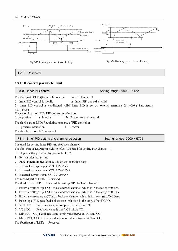
VICSION VS500
VS500 series of general purpose inverter Duxe.ru
72
6.9 PID control parameter unit The first part of LED(form right to left): Inner PID control 0:Inner PID control is invalid 1:Inner PID control is valid 2:Inner PID control is conditional valid. Inner PID is set by external terminals X1~X6 ( Parameters F3.0~F3.5) The second part of LED: PID controller selection 0: proportion 1:Integral 2:Proportion and integral The third part of LED: Regulating property of PID controller 0: positive interaction 1:Reactor The fourth part of LED: reserved It is used for setting inner PID and feedback channel. The first part of LED(form right to left):It is used for setting PID channel 。 0:Digital setting. It is set by parameter F8.2. 1:Serials interface setting 2:Panel potentiometer setting, it is on the operation panel. 3:External voltage signal VC1(0V~5V)。 4:External voltage signal VC2(0V~10V)。 5:External current signal CC(0~20mA)。 The second part of LED: Reserved. The third part of LED: It is used for setting PID feedback channel. 0:External voltage input VC1 is as feedback channel, which is in the range of 0~5V. 1:External voltage input VC2 is as feedback channel, which is in the range of 0~10V. 2:External current input CC is as feedback channel, which is in the range of 0~20mA. 3:Pulse input PLS is as feedback channel, which is in the range of 0~50 KHz. 4:VC1+CC Feedback value is composed of VC1 and CC 5:VC1-CC Feedback value is that VC1 minus CC. 6:Min (VC1, CC) Feedback value is min value between VC1and CC 7:Max (VC1, CC) Feedback value is max value between VC1and CC The fourth part of LED: Reserved
[F7.2]
External freq. set by [F0.1]
Preset center freq. of
wobble freq.
[F7.7]
Amplitude of
wobble freq.
[F7.1]
[F7.4] ×Amplitude of wobble freq.
[F7.5] [F7.6]
Running freq
时间
摆频幅值
[F7.1]
Running freq
t
Break in wobble freq. and restart
Running instrument
Wobble freq.
Fig.6-27 Running process of wobble freq Fig.6-28 Running process of wobble freq
F7.8 Reserved
F8.0 Inner PID control Setting range:0000 ~ 1122
F8.1 inner PID setting and channel selection Setting range:0000 ~ 5705

Duxe.ru VICSION VS500
VS500 series of general purpose inverter Duxe.ru
73
Expected feedback value
[F8.6]
[F8.5]
[F8.3] [F8.4]
PID setting value
If F8.1 is 0#00, setting value will be set by F8.2. Parameters F8.3 and F8.4 define the upper and lower limit value of PID setting. Parameters F8.5 and F8.6 define corresponding relation with PID feedback value. Shown as fig.6-29 Those parameters are inner parameter of PID. The parameter is the allowable deviation value relative to the setting max value. When the difference between feedback value and the setting value is lower than this setting value, PID controller will stop. Shown as fig.6-30. This function is mainly suited for the system that has lower control precision and needs to avoid adjusting frequently, for example, water-supply with constant pressure system. Those parameters define freq. and running time of inverter before actual PID control is valid. In some control systems, inverters will forcible output a certain freq. (F8.10) and keep it in setting time (F8.11) for controlled object arrives fast targeted value. When controlled object almost arrives targeted value, PID controller will be valid to improve response speed.
F8.2 Inner PID close-loop digital setting Setting range:0.0 ~ 10.00V
F8.3 Minimum fixed value Setting range:0.0 ~ [F8.4] F8.4 Maximum fixed value Setting range:[F8.3] ~ 10.00 F8.5 Feedback of minimum fixed value Setting range:0.0 ~ 10.00 F8.6 Feedback of maximum fixed value Setting range:0.0 ~ 10.00
Fig.6-29 Relation between PID fixed value and expected feedback value
F8.7 Proportion gain Setting range:0.0 ~ 5.00 F8.8 Integral time constant Setting range:1.0 ~ 100 Sec
F8.9 Allowable deviation limit Setting range:0.0 ~ 20.0(%)
f
t
PID action
[F8.9]
PID action
PID setting PID feedback
Fig.6-30 PID Control allowable deviation limit
F8.10 Preset freq. for close-loop Setting range:0.00 ~ the upper limit freq. F8.11 Holding time of preset freq. for close-loop Setting range:0.0 ~ 6000.0s
F8.12 long-distance manometer range Setting range:0.00~20.000Mpa

VICSION VS500
VS500 series of general purpose inverter Duxe.ru
74
It defines measuring range of long-distance manometer, user have to input it.
It defines feedback value while inverter goes sleep state. When actual feedback value is larger than setting value and inverter arrives lower limit value, the inverter will go sleep. It defines feedback value while inverter is in the state of sleeping. When actual feedback value is less than setting value, the inverter will be in the sleepy state. The inverter will wait [F8.15] to switch modes, if the inverter receives satisfied sleep or awakening condition. Shown as fig.6-31. When PID controller operates, switching time of sleeping/awakening mode is shown as fig.6-31. It is used for setting the upper and lower limit pressure value. 6.10 Communication function parameter units
The first part of LED(form right to left): It is used for setting baud rate of serials communication. 0: Reserved 1:1200bps 2: 2400bps 3: 4800bps 4: 9600bps 5: 19200bps To make sure both sides have the same baud rate, when client use serials communication. The second part of LED: To set data format of serials communication. 0:Close 1: Even 2:Odd To make sure both sides have the same data format, when client use serials communication. The third and fourth part of LED: Reserved
F8.13 Sleeping threshold Setting range: [F8.14]~[F8.12]
F8.14 Awakening threshold Setting range::0.0~[F8.13]
[F8.13]
Lower limit freq [F0.7]
PID feedback value Sleeping threshold
output freq
PID setting
[F8.14] Awakening threshold
[F8.15] [F8.15] Sleeping Awakening
Fig.6-31 Sleep and awakening function of PID
F8.15 Switching time of Sleeping/Awakening mode Setting range::0.0~[F8.13]
F8.16 upper limit pressure value Setting range:[F8.13]~[F8.12] Mpa F8.17 Lower limit pressure value Setting range:0.0 ~ 6000.0s
F8.18~F8.24 Reserved
F9.0 Communication setting Setting range:0000 ~ 0025
F9.1 Local address Setting range:0 ~ 30
F9.2 Response delay of local Setting range:0 ~ 1000 ms

Duxe.ru VICSION VS500
VS500 series of general purpose inverter Duxe.ru
75
Auxiliary freq
[F9.8]
-[F9.8] 0 Setting channel input
It defines waiting time, which is the time form local receives correctly code to send response data frames
The first part of LED(form right to left): 0: The inverter is slave 1: The inverter is master The second part of LED: Act selection after communication is lost 0: Stop 1:Keep The third part of LED:Linkage jog 0:Jog synchronized 1:Jog asynchronous The fourth part of LED:Linkage control synchronized frequency source 0:Setting frequency 1:Output frequency
If the machine itself doesn’t receive correct data signals in regulate time, the communication is fault. Inverter will keep on running or stop according to setting of parameter F9.3 It is used for setting proportion of output freq. between master and slave, when takes linkage setting control. When F9.6 is 0, rectify channel of linkage setting proportion is invalid. Slave freq. = Master freq. × [F9.5]
When F9.6 is 1, 2, 3 or 4, rectify channel of linkage setting proportion is valid. When the lower limit value of rectify channel is selected, The rectify coefficient is 0.5; when the upper limit value of rectify channel is selected, the rectify coefficient is 2.0, Slave freq. = Master freq. × [F9.5] ×rectify coefficient(0.50~2.00) F9.6 is used for selecting rectify channel. Rectify channel 1:Panel potentiometer Rectify channel 2:External voltage signal VC1(0 ~ 5V) Rectify channel 3:External voltage signal VC2(0 ~ 10V) Rectify channel 4:External current signal CC(0 ~ 20mA) It is used for selecting the setting channel of guest inverter auxiliary freq. and amplitude of auxiliary freq When the input value of auxiliary freq. setting channel is middle value,auxiliary freq. is 0, Slave output freq. = master instruction freq. ×linkage proportion+auxiliary freq. (Linkage proportion is set by [F9.5] 、 [F9.6])
F9.3 Function setting of communication Auxiliary function Setting range:0000 ~ 1111
F9.4 Checkout time of communication overtime Setting range:0.0 ~ 100.0 Sec
F9.5 linkage setting proportion Setting range: 0.010 ~ 10.000 F9.6 Rectify channel of linkage setting proportion Setting range: 0 ~ 4
F9.7 Setting channel of guest inverter auxiliary freq. Setting range: 0.010 ~ 10.000 F9.8 Amplitude of auxiliary freq Setting range:0.0~25.00 Hz
Fig.6-32 Adjust amplitude of auxiliary freq

VICSION VS500
VS500 series of general purpose inverter Duxe.ru
76
These parameters are used for setting load self-equilibrium function ,in linkage synchronous running mode, master inverter is equals an inverter plus a high-precision synchronizer, usually can get high-precision freq. Synchronous. In some application field, load of inverter group should keep balanced so that all the transmission chain tension or velocity strict agreement. VS500 serial of inverter has loaded self- equilibrium function when inverters are in linkage running mode.
When the load self- equilibrium function is valid, master inverter will transfer the load information to every slave inverter, and every slave inverter will adjust the load instructions according the master. When the certain slave inverter should to bear a heavier load, it could change through [F9.10]. The value is greater, the load capacity is heavier. Load self- equilibrium below 5Hz, the effect limited. Only if each master and slave inverter has good linkage ratio coefficient, the self- equilibrium function is valid. If the adjust is not obvious, please increase parameter [F9.11] 6.11 Special function parameter unit It defines lower limit voltage which terminals P+ and P- are allow while inverter is working normally. For some low voltage conditions, user can decrease under voltage protection level to ensure that inverter is running normally It defines threshold of voltage stall protection while motor is decelerating. If DC voltage caused by decelerating is beyond setting value of FC.1, deceleration time will automatic prolong. Shown as fig 6-33 It defines the max output current which is permitted by inverter. Whatever the operation mode is, inverter will adjust output freq. to inhibit current within the range of regulation, when output current of inverter is beyond setting value of FC.2.
F9.9 Load self- equilibrium function Setting range:0~1 F9.10 Load self- equilibrium proportion Setting range:0.50~2.00 F9.11 Trimming range of load self- equilibrium freq Setting range:0.0~5.00
FC.0 Under voltage protection level Setting range: 360V ~ 460V
FC.1 over voltage limit level Setting range: 660V ~ 760V
[FC.1]
f
t
t
Adjust Dec time
DC voltage
Fig 6-33 Voltage stall protection in Dec
FC.2 current amplitude limiting level Setting range: 150 ~ 200%
FC.3 Reserved
FC.4 Reserved

Duxe.ru VICSION VS500
VS500 series of general purpose inverter Duxe.ru
77 It is used for setting some coefficients with special function in running process. Generally, user needn’t set.
The first part of LED(form right to left): Under voltage compensation intensity The second part of LED: Over voltage inhibit intensity The third part of LED: Over current inhibit intensity The fourth part of LED:Self-adapting braking torque adjust intensity
The first part of LED(form right to left): Cooling fan control 0:Cooling fan run after inverter run. Cooling fan will stop after inverter stop. When temperature is above 40℃,the cooling fan also will also run. 1:Cooling fan will automatic run when inverter is power on.
The second part of LED:Reserved. The third part of LED: Voltage over modulation
0:Invalid 1:Valid The fourth part of LED:Reserved
The first part of LED(form right to left):Forbid to modify parameter. 0:Invalid. 1:Valid.
When it forbids modifying parameter is valid, [F0.18] will be invalid, if you want to get new password, please ask for our service department. This function is used for preventing modify parameter wrongly.
The second part of LED:Input terminal effective level. 0:Low level (terminals is connected) 1:High level (terminals is disconnected) The third part of LED: Reserved The fourth part of LED:Selection of rotate speed display proportion 0: the coefficient of rotational speed display is valid Rotational speed display=Rotational speed×Rotator speed coefficient setting (F6.11 1: the deceleration proportion is valid Rotational speed display=Rotate speed / Rotator speed coefficient setting(F6.11)
It is read-only parameter.
FC.5 Action function selection Setting range: 0000 ~ 0111
FC.6 Auxiliary functions Setting range:0000~0011
FC.7 Reserved
FC.8 Agency password Setting range:0 ~ 9999
FC.9~ FC.10 Reserved
FC.11 Oscillatory inhibiting factor Setting range: 0.0~ 2.00
FC.12 Reserved
FC.13 Program version Range: 1600 ~ 1699
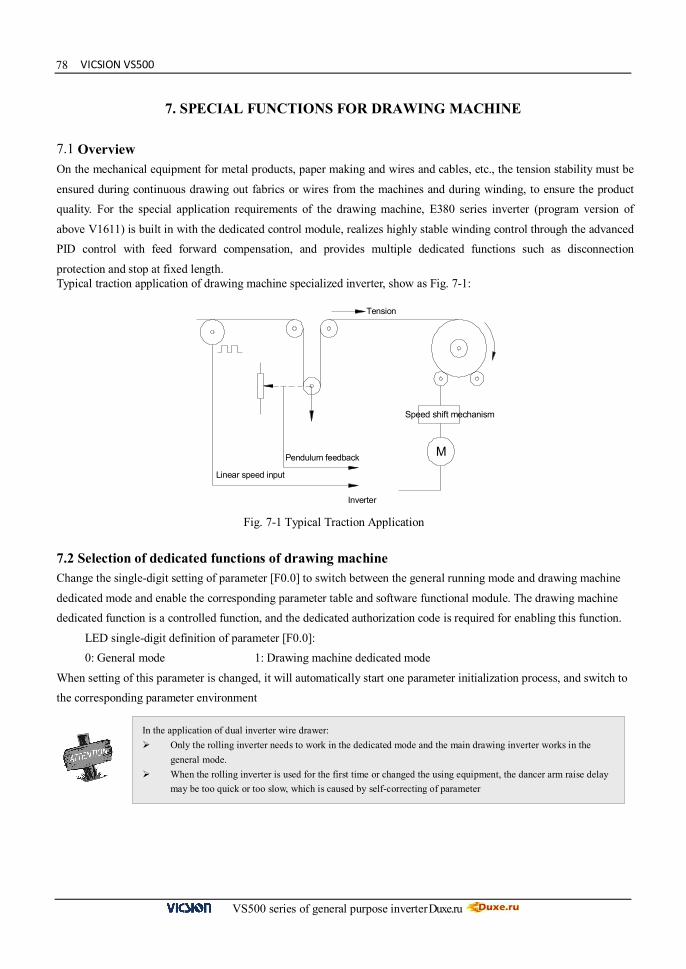
VICSION VS500
VS500 series of general purpose inverter Duxe.ru
78
7. SPECIAL FUNCTIONS FOR DRAWING MACHINE
7.1 Overview On the mechanical equipment for metal products, paper making and wires and cables, etc., the tension stability must be
ensured during continuous drawing out fabrics or wires from the machines and during winding, to ensure the product quality. For the special application requirements of the drawing machine, E380 series inverter (program version of
above V1611) is built in with the dedicated control module, realizes highly stable winding control through the advanced PID control with feed forward compensation, and provides multiple dedicated functions such as disconnection
protection and stop at fixed length. Typical traction application of drawing machine specialized inverter, show as Fig. 7-1: 7.2 Selection of dedicated functions of drawing machine Change the single-digit setting of parameter [F0.0] to switch between the general running mode and drawing machine
dedicated mode and enable the corresponding parameter table and software functional module. The drawing machine dedicated function is a controlled function, and the dedicated authorization code is required for enabling this function.
LED single-digit definition of parameter [F0.0]: 0: General mode 1: Drawing machine dedicated mode
When setting of this parameter is changed, it will automatically start one parameter initialization process, and switch to the corresponding parameter environment
Fig. 7-1 Typical Traction Application
In the application of dual inverter wire drawer: Only the rolling inverter needs to work in the dedicated mode and the main drawing inverter works in the
general mode. When the rolling inverter is used for the first time or changed the using equipment, the dancer arm raise delay
may be too quick or too slow, which is caused by self-correcting of parameter
Linear speed input
Tension
Speed shift mechanism
M Pendulum feedback
Inverter

Duxe.ru VICSION VS500
VS500 series of general purpose inverter Duxe.ru
79
7.3 Parameter table of drawing machine dedicated function ([F0.0] =0001)
Parameter Type
Code Name Probable Causes Min. Unit
Factory Value
Modification Limited
F0.0 Running mode
selection
LED bits : Running mode 0:General mode 1:Special for drawing machine LED tens: Reserved LED hundreds: Reserved LED thousands: Reserved
1 0001 ★
F0.1 Frequency input channel / mode selection
0:Frequency setting by operation panel
1:UP/DW Acc and Dec control
2:RS485 interface
3:Panel potentiometer
4:External voltage signal VC1(0V~5V)
5:External voltage signal VC2(0V~10V)
6:External current signal CC(0~20mA)
7:External pulse signal(0.0~50.0KHz)
8:Combination setting
9:External terminals
1 2
F0.2 Frequency digital setting
0.00~ the upper limit frequency 0.01 0
F0.3 Auxiliary control of freq. Digital setting
The first part of LED(form right to left): 0:Setting freq. will save after power down 1:Setting freq. will not save after power down The second part of LED: 0:Setting freq. is to keep when stopping
1:Setting freq. will save in F0.2 when stopping 2:Setting freq. is clear when stopping The third and fourth part of LED(form right to left):Reserved
1 0021
The drawing machine dedicated parameter table can be used in comparison with the general parameter table, wherein, the parameters in the shaded part are somewhat different from the parameters in the general parameter table (with different value or definition), other parameters are identical with that defined in the general parameter table, and please refer to the description of the general parameter table for the corresponding description and user guide.
Description of marks in the functional parameter table: “★” means that the parameter cannot be changed during the running; “▲” means that the parameter is associated with the inverter model.
The
basic
ope
ratio
n pa
ram
eter
s
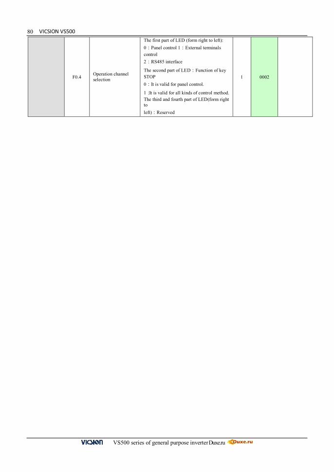
VICSION VS500
VS500 series of general purpose inverter Duxe.ru
80
F0.4 Operation channel selection
The first part of LED (form right to left): 0:Panel control 1:External terminals control 2:RS485 interface
The second part of LED:Function of key STOP 0:It is valid for panel control.
1:It is valid for all kinds of control method. The third and fourth part of LED(form right to left):Reserved
1 0002
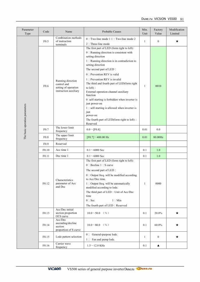
Duxe.ru VICSION VS500
VS500 series of general purpose inverter Duxe.ru
81
Parameter Type
Code Name Probable Causes Min. Unit
Factory Value
Modification Limited
F0.5
Combination methods of instruction terminals
0:Two-line mode 1 1:Two-line mode 2
2:Three-line mode 1 0 ★
F0.6
Running direction control and setting of operation instruction auxiliary
The first part of LED (form right to left): 0:Running direction is consistent with setting direction 1:Running direction is in contradiction to setting direction The second part of LED:
0:Prevention REV is valid
1:Prevention REV is invalid The third and fourth part of LED(form right to left): External operation channel auxiliary function 0:self-starting is forbidden when inverter is just power-on 1:self-starting is allowed when inverter is just power-on The fourth part of LED(form right to left): Reserved
1 0010
F0.7 The lower limit frequency 0.0~[F0.8] 0.01 0.0
F0.8 The upper limit frequency [F0.7]~400.00 Hz 0.01 80.00Hz
F0.9 Reserved
F0.10 Acc time 1 0.1~6000 Sec 0.1 1.0
F0.11 Dec time 1 0.1~6000 Sec 0.1 1.0
F0.12 Characteristics parameter of Acc and Dec
The first part of LED (form right to left): 0:Beeline 1:S curve
The second part of LED:
0:Output freq. will be modified according to Acc/Dec time. 1:Output freq. will be automatically modified according to lode. The third part of LED:Unit of Acc/Dec time 0:Sec 1:Min
The fourth part of LED:Reserved
1 0000
F0.13 Acc/Dec initial section proportion Of S curve
10.0~50.0 (%) 0.1 20.0% ★
F0.14
Acc/Dec ascending/decline section proportion of S curve
10.0~80.0 (%) 0.1 60.0% ★
F0.15 Lode pattern selection 0: General-purpose lode.
1: Fan and pump lode. 1 0 ★
F0.16 Carrier wave frequency 1.5~12.0 KHz 0.1 ▲
The
basic
ope
ratio
n pa
ram
eter
s

VICSION VS500
VS500 series of general purpose inverter Duxe.ru
82
Parameter Type Code Name Probable Causes
Min. Unit
Factory Value
Modification Limited
F0.17 Carrier wave characteristics
The first part of LED (form right to left): Reserved The second part of LED:
0:Load carrier wave adjustment is invalid
1:Load carrier wave adjustment is valid
The third part of LED:
0:Heat carrier wave adjustment is invalid
1:Heat carrier wave adjustment is valid
The fourth part of LED:
0:Freq. relating carrier wave adjustment is Invalid 1:Freq. relating carrier wave adjustment is valid
1 1110
F0.18 Parameter write-protection
1:Forbid to modify all parameter, except F0.2 and F0.18 2:Forbid to modify all parameter, except F0.18 Other values: all parameters are allowed to modify
1 0
F1.0 Type of V/F Curve
0:Constant torque curve
1:Low-freq. torque curve 1
2:Low-freq. torque curve 2
3:V/F user-defined curve
1 3 ★
F1.1 Torque Boost 0.0~20.0(%) 0.1 ▲
F1.2 Torque boost pattern 0:Manual 1:Automatic 1 0 ★
F1.3 Basic running frequency 5.00~the upper limit frequency 0.01 50.00
F1.4 Max output voltage 200~500V /100~250V 1 400 220
F1.5 V/F freq. 3 [F1.7]~[F1.3] 0.01 30.00 ★
F1.6 V/F voltage 3 [F1.8]~100.0(%) 0.1 65.0 ★
F1.7 V/F freq. 3 [F1.9]~[F1.5] 0.01 20.00 ★ F1.8 V/F voltage 2 [F1.10]~[F1.6] 0.1 50.00 ★ F1.9 V/F freq. 1 0.0~[F1.7] 0.01 10.00 ★
F1.10 V/F voltage 1 [F1.1]~[F1.8] 0.1 25.0 ★
F1.11 DC braking current when starting 0.0~100.0(%) 0.1 50.0
F1.12 DC braking time when starting 0.0~20.0Sec 0.1 0 ★
F1.13 ~
F1.18 Reserved
F2.0 ~
F2.18 The same with the general definition of parameters, please refer to the general parameter table
The
basic
ope
ratio
n pa
ram
eter
s Th
e pr
imar
y app
licat
ion
of p
aram
eter

Duxe.ru VICSION VS500
VS500 series of general purpose inverter Duxe.ru
83
Parameter Type
Code Name Probable Causes Min. Unit
Factory Value
Modification Limited
F3.0 Function selection of input terminal 1 (0~35)
0:Control terminal is idle
1:Multi-speed control terminal 1
2:Multi-speed control terminal 2
3:Multi-speed control terminal 3
4:Wobble freq. is valid
5:State of wobble freq. reset
6:FWD jog control
7:REV jog control
8:Acc& Dec time selection terminal 1
9:Acc& Dec time selection terminal 2
10:Freq. setting channel selection 1
11:Freq. setting channel selection 2
12:Freq. setting channel selection 3
13:Freq. is controlled gradually increase (UP) 14:Freq. is controlled gradually decrease (DW) 15:UP-DW freq. clear
16:Uncontrolled stop control
17:Fault signal of peripheral equipment input 18:Three-line mode running control
19:DC braking control
20:Inner counter clear
21:Inner counter timer
22:PLC running valid
23:PID running valid
24:Internal timer trigger terminal
25:PLC state reset after stopping
26:Multi-speed control terminal 4 27~30: Reserved 31: Coil diameter reset 32: Initial coil diameter selection terminal 1 33: Position switch 34: Disconnection proximity switch 35: Disconnection reset / Brake release
1 1 ★
F3.1 Function selection of input terminal 2 (0~35)
1 16 ★
F3.2 Function selection of input terminal 3 (0~35)
1 3 ★
F3.3 Function selection of input terminal 4 (0~35)
1 6 ★
F3.4 Function selection of input terminal 5 (0~35)
1 34 ★
F3.5 Function selection of input terminal 6 (0~35)
1 35 ★
F3.6 Output terminal OC1
0: Inverter in running 1: Frequency reaching 2: Freq. level detection signal (FDT) 3: Over-loading alarm 4: External fault halt 5: Output frequency reaches the upper-limit 6: Output frequency reaches the lower-limit 7: Running in zero speed 8: Under voltage shutdown 9: PLC stage is end of run 10: PLC periodic is end of run 11: Internal timer arrives regular time 12: Setting value of counter arrival 13: Designated value of counter arrival
1 2
F3.7 Output terminal OC2 1 22
Dig
ital O
/I pa
ram
eter
s
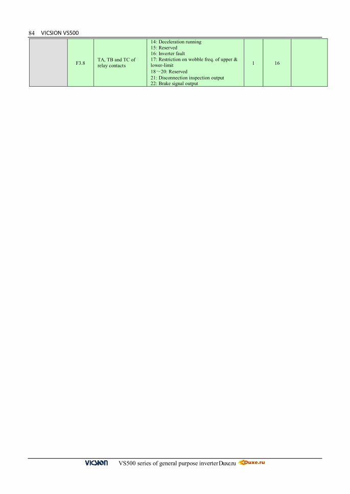
VICSION VS500
VS500 series of general purpose inverter Duxe.ru
84
F3.8 TA, TB and TC of relay contacts
14: Deceleration running 15: Reserved 16: Inverter fault 17: Restriction on wobble freq. of upper & lower-limit 18~20: Reserved 21: Disconnection inspection output 22: Brake signal output
1 16
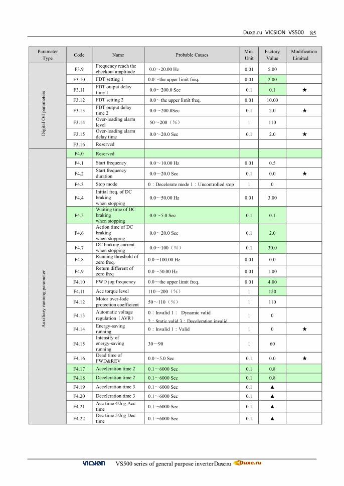
Duxe.ru VICSION VS500
VS500 series of general purpose inverter Duxe.ru
85
Parameter Type
Code Name Probable Causes Min. Unit
Factory Value
Modification Limited
F3.9 Frequency reach the checkout amplitude 0.0~20.00 Hz 0.01 5.00
F3.10 FDT setting 1 0.0~the upper limit freq. 0.01 2.00
F3.11 FDT output delay time 1 0.0~200.0 Sec 0.1 0.1 ★
F3.12 FDT setting 2 0.0~the upper limit freq. 0.01 10.00
F3.13 FDT output delay time 2 0.0~200.0Sec 0.1 2.0 ★
F3.14 Over-loading alarm level 50~200(%) 1 110
F3.15 Over-loading alarm delay time 0.0~20.0 Sec 0.1 2.0 ★
F3.16 Reserved F4.0 Reserved
F4.1 Start frequency 0.0~10.00 Hz 0.01 0.5
F4.2 Start frequency duration 0.0~20.0 Sec 0.1 0.0 ★
F4.3 Stop mode 0:Decelerate mode 1:Uncontrolled stop 1 0
F4.4 Initial freq. of DC braking when stopping
0.0~50.00 Hz 0.01 3.00
F4.5 Waiting time of DC braking when stopping
0.0~5.0 Sec 0.1 0.1
F4.6 Action time of DC braking when stopping
0.0~20.0 Sec 0.1 2.0
F4.7 DC braking current when stopping 0.0~100(%) 0.1 30.0
F4.8 Running threshold of zero freq. 0.0~100.00 Hz 0.01 0.0
F4.9 Return different of zero freq 0.0~50.00 Hz 0.01 1.00
F4.10 FWD jog frequency 0.0~the upper limit freq. 0.01 4.00
F4.11 Acc torque level 110~200(%) 1 150
F4.12 Motor over-lode protection coefficient 50~110(%) 1 110
F4.13 Automatic voltage regulation(AVR)
0:Invalid 1: Dynamic valid
2:Static valid 3:Deceleration invalid 1 0
F4.14 Energy-saving running 0:Invalid 1:Valid 1 0 ★
F4.15 Intensify of energy-saving running
30~90 1 60
F4.16 Dead time of FWD&REV 0.0~5.0 Sec 0.1 0.0 ★
F4.17 Acceleration time 2 0.1~6000 Sec 0.1 0.8
F4.18 Deceleration time 2 0.1~6000 Sec 0.1 0.8
F4.19 Acceleration time 3 0.1~6000 Sec 0.1 ▲
F4.20 Deceleration time 3 0.1~6000 Sec 0.1 ▲
F4.21 Acc time 4/Jog Acc time 0.1~6000 Sec 0.1 ▲
F4.22 Dec time 5/Jog Dec time 0.1~6000 Sec 0.1 ▲
Aux
iliar
y ru
nnin
g pa
ram
eter
D
igita
l O/I
para
met
ers

VICSION VS500
VS500 series of general purpose inverter Duxe.ru
86
Parameter Type Code Name Probable Causes
Min. Unit
Factory Value
Modification Limited
F4.23 Modified rated of UP/DW terminals 0.01~100.0 Hz/Sec 0.01 10.00Hz
F4.24 Start voltage of dynamic braking 600~750 V 1 700V
F4.25 Action ratio of dynamic braking 10~100(%) 1 60%
F4.26 Restart after power down setting
The first part of LED:
0:Invalid 1:Valid
The second part of LED:
0:Routine mode
1:Detect speed and restart mode
The third and fourth part of LED:Reserved
1 0010 ★
F4.27 Waiting time of restart after power down
0.0~10.0 Sec 0.1 0.5 ★
F4.28 REV jog frequency 0.0~the upper limit freq. 0.01 4.00
F5.0 ~
F5.26 Reserved
F6.0 ~
F6.19 The same with the general definition of parameters, please refer to the general parameter table
F7.0 PID feedback channel selection/Pendulum feedback input
0: VC1 input 1: VC2 input 2: CC input 3: PLS input
1 0 ★
F7.1 PID function setting
LED bits: PID function selection 0: PID off 1: PID function valid LED tens: PID parameter adjustment 0: Use 1st group parameters only 1: Adjust by coil diameter 2: Adjust by running freq. LED hundreds: PID output polarity (only valid for straight wire drawing machine ) 0: Positive 1: Negative LED thousands: special function to slow down pendulum arising speed 0: valid 1: invalid
1 0021
F7.2 The proportional gain 1 0.0~6000.0 Sec 0.01 1.00
F7.3 Integral time 1 0.0~50.0(%) 0.1 10.0
F7.4 Derivative time 1 0.0~80.0(%) 0.01 2.00
F7.5 Proportional gain 2 0.1~1000.0 Sec 0.01 1.00
F7.6 Integral time 2 0.1~1000.0 Sec 0.1 15.0
F7.7 Derivative time 2 0.0~the upper limit freq 0.01 5.00
F7.8 PID upper limit limiter 5~50 % 1% 20% F8.0 Start delay gain 1.0~100.0 0.1 10.0 ★
F8.1 Initial operating freq. 0.0~50.00 Hz 0.01 6.00 ★
F8.2 PID error limiter 5.0~100.0 % 0.1 20.0
F8.3 Mechanical transmission ratio 0.01~300.0 0.01 1.00
F8.4 Max. coil diameter 10mm~10000mm 1 400
F8.5 Reel diameter 1 10mm~10000mm 1 220
Aux
iliar
y ru
nnin
g pa
ram
eter
W
indi
ng P
ID c
ontro
l Pa
ram
eter
s spe
cial
fo
r dra
win
g m
achi
ne

Duxe.ru VICSION VS500
VS500 series of general purpose inverter Duxe.ru
87F8.6 Reel diameter 2 10mm~10000mm 1 100
Parameter Type
Code Name Probable Causes Min. Unit
Factory Value
Modification Limited
F8.7
Coil diameter filter time
0.50~100.00 Sec 0.01 10.00s
F8.8 Linear speed input source
0: No input 1: VC1 input 2: VC2 input 3: CC input 4: PLS input
1 0
F8.9 Max. linear speed 0.1m/Min~6500.0m/Min 0.1m/Min 2500.0
F8.10 Coil diameter calculation min. Linear speed
0.1m/Min~6500.0m/Min 0.1m/Min
500.0
F8.11 Pendulum stable point setting
20.0~80.0(%) 0.1 50.0
F8.12 Disconnection detection method
0: Invalid 1: To detect by disconnection proximity switch signal 2: To detect by PID feedback (pendulum signal)
1 0
F8.13 Min. Freq. of disconnection detection
0.00~50.00Hz 0.01Hz
10.00Hz
F8.14 Upper limit value of disconnection detection
0.1%~50.0% 0.10%
10.0%
F8.15 Disconnection detection start delay time
0.1Sec~60.0 Sec 0.10% 6.0s
F8.16 Disconnection detection judgment delay time
0.1Sec~60.0 Sec 0.10%
2.0s
F8.17 Disconnection fault auto reset
0: Invalid 1: Valid 1 0
F8.18 Disconnection fault auto reset interval time
1.0~99.0 Sec 0.1 15.0 s
F8.19 Brake signal start freq. 0.0~50.00 Hz 0.01 1.50 Hz
F8.20 Braking time 0.1~100.0 Sec 0.1 3.0 s
F8.21 Setting length arrives action selection
LED bits: fixed length to stop 0: No action 1: Stop LED tens: fixed length stop method 0: setting length arrival 1: Max. Coil diameter arrival 2: Each of setting length and max. coil diameter arrival
1 0000
F8.22 Proportion of high & low grade
0.01~100.00 0.01 1.00
F8.23 Winding motor pole pairs
1~8 1 2
F8.24 Preset length 1.00~650.0 KM 0.01 300.0
Para
met
ers s
peci
al fo
r dra
win
g m
achi
ne

VICSION VS500
VS500 series of general purpose inverter Duxe.ru
88
Parameter Type Code Name Probable Causes
Min. Unit
Factory Value
Modification Limited
F9.0 Communication setting
The first part of LED(form right to left): It is used to set baud rate of serials Communication. 0: Reserved 1:1200bps 2: 2400bps 3: 4800bps 4: 9600bps 5: 19200bps The second part of LED: To set data format of serials communication. 0:Close 1: Even 2:Odd The third and fourth part of LED: Reserved.
1 0014 ★
F9.1 Local address 0~30 1 0
F9.2 Response delay of local 0~1000 ms 1 5ms
F9.3 Function setting of communication Auxiliary function
The first part of LED(form right to left):
0:The inverter is guest 1: The inverter is host The second part of LED: Act selection after communication is lost 0:Stop 1:Keep
The third part of LED:linkage jog
0:jog synchronized
1:jog asynchronous
The fourth part of LED:linkage control synchronized frequency source 0:setting frequency
1:output frequency
1 0010
F9.4 Checkout time of communication overtime
0.0~100.0 Sec 0.1 10.0
F9.5 Linkage setting proportion 0.010~10.000 0.01 1.000
F9.6 Rectify channel of linkage setting proportion
0:close 1:Panel potentiometer
Rectify channel 2:External voltage signal VC1 (0 ~ 5V)
Rectify channel 3:External voltage signal VC2 (0 ~ 10V)
Rectify channel 4:External current signal CC (0 ~ 20mA)
1 0
F9.7 ~
F9.11 Reserved
FC.0 ~
FC.5 The same with the general definition of parameters, please refer to the general parameter table
Com
mun
icat
ion f
unct
ion
para
met
ers
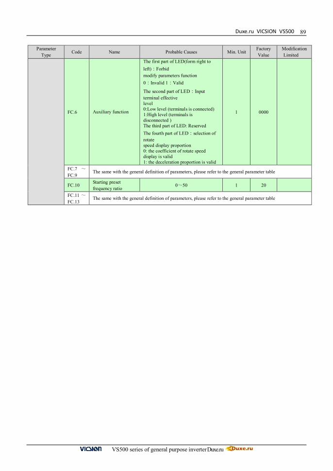
Duxe.ru VICSION VS500
VS500 series of general purpose inverter Duxe.ru
89
Parameter Type Code Name Probable Causes Min. Unit
Factory Value
Modification Limited
FC.6 Auxiliary function
The first part of LED(form right to left):Forbid modify parameters function 0:Invalid 1:Valid
The second part of LED:Input terminal effective level 0:Low level (terminals is connected) 1:High level (terminals is disconnected ) The third part of LED: Reserved The fourth part of LED:selection of rotate speed display proportion 0: the coefficient of rotate speed display is valid 1: the deceleration proportion is valid
1 0000
FC.7 ~
FC.9 The same with the general definition of parameters, please refer to the general parameter table
FC.10 Starting preset frequency ratio
0~50 1 20
FC.11 ~
FC.13 The same with the general definition of parameters, please refer to the general parameter table

VICSION VS500
VS500 series of general purpose inverter Duxe.ru
90
8. TROUBLESHOOTING AND MEASURES
8.1 Protective functions and Countermeasures
Code Faults Probable Causes Solutions
Fu.01 Over-current during Acc
1、Acceleration time is too short. 2、V/F curve is not suitable 3、You hasn’t set the right motor parameters 4、User start rotating motor, but doesn’t set function of
detect speed and restart. 5、Value of torque boost set too high. 6、Power grid voltage is too low
1. Prolong the acceleration time 2. Descend the torque boost or adjust the V/F curve 3. Input motor’s parameter once again and do
self-determination to parameter. 4. To set function of detecting speed and restart 5. To decrease voltage of torque boost 6. Check power grid voltage, and reduce power then use
Fu.02 over-current during Dec Deceleration time is too short. Prolong the deceleration time
Fu.03 Over-current during Running or stopping
1. Load occurs mutation 2. Power grid voltage is too low
1. Decrease load fluctuation 2. Check power supply voltage.
Fu.04 over-voltage during Acc
1.Input voltage is too high 2. Power supply is switched on or off frequently.
1. Check power supply voltage 2.Decrease setting value of F4.11 3. Control the on-off of inverter by the control terminal
Fu.05 over-voltage during Dec
1. Deceleration time is too short. 2. Input-voltage is abnormal
1. Extend the deceleration time 2. Check power supply voltage 3. Install or select the brake resistance
Fu.06 over-voltage during running
1. Power supply is abnormal 2. There are energy feedback load
1. Check power supply 2. Install or select brake resistor
Fu.07 over-voltage during stop Power supply is abnormal Check power supply voltage
Fu.08 Under-voltage during running
1. Power supply is abnormal 2. There is great fluctuation of load into electric network.
1. Check power supply voltage 2. Provide the power supply separately
Fu.09 protective action of inverter
1. Output is short-circuit or ground 2. Load is too heavy
1. Check wiring 2. Reduce the load 3. Check whether brake resistor is short-circuit
Fu.10 Output grounding 1.The output terminal of inverter grounds 2. The wire is too long between inverter and motor and the carrier frequency is too high.
1. Check the connecting wire 2. Shorten the connection wire or reduce the carrier frequency.
Fu.11 Interfere of inverter Fault action caused by disturbance of electromagnetism Add absorb circuit around inverter
Fu.12 Inverter over-loading
1. Load is too heavy. 2. Acceleration time is too short. 3. Torque boost is too high or V/F curve is not
suitable. 4. Voltage of Power supply is too low 5. User start rotating motor, but doesn’t set function of detecting speed and restart.
1. Reduce the load or replace with higher capacity inverter. 2. Prolong Acc time. 3. Decrease the torque boost or adjusting V/F curve. 4. Check Voltage of Power supply 5. To set function of detect speed and restart
Fu.13 Motor over-loading
1. Load is too heavy. 2. Acceleration time is too short. 3. The setting of protection factor is too small 4. Torque boost is too high or V/F curve is not suitable.
1. Reduce the load 2. Prolong Acc time 3. Increase the over-loading protection
factor of motor( [F4.12]) 4. Decrease torque boost voltage and adjust
V/F curve.
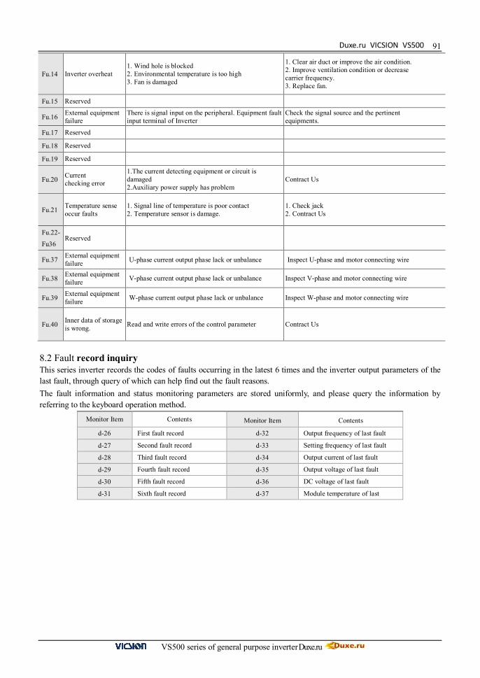
Duxe.ru VICSION VS500
VS500 series of general purpose inverter Duxe.ru
91
Fu.14 Inverter overheat 1. Wind hole is blocked 2. Environmental temperature is too high 3. Fan is damaged
1. Clear air duct or improve the air condition. 2. Improve ventilation condition or decrease carrier frequency. 3. Replace fan.
Fu.15 Reserved
Fu.16 External equipment failure
There is signal input on the peripheral. Equipment fault input terminal of Inverter
Check the signal source and the pertinent equipments.
Fu.17 Reserved
Fu.18 Reserved
Fu.19 Reserved
Fu.20 Current checking error
1.The current detecting equipment or circuit is damaged 2.Auxiliary power supply has problem
Contract Us
Fu.21 Temperature sense occur faults
1. Signal line of temperature is poor contact 2. Temperature sensor is damage.
1. Check jack 2. Contract Us
Fu.22-
Fu36 Reserved
Fu.37 External equipment failure U-phase current output phase lack or unbalance Inspect U-phase and motor connecting wire
Fu.38 External equipment failure V-phase current output phase lack or unbalance Inspect V-phase and motor connecting wire
Fu.39 External equipment failure W-phase current output phase lack or unbalance Inspect W-phase and motor connecting wire
Fu.40 Inner data of storage is wrong. Read and write errors of the control parameter Contract Us
8.2 Fault record inquiry This series inverter records the codes of faults occurring in the latest 6 times and the inverter output parameters of the last fault, through query of which can help find out the fault reasons. The fault information and status monitoring parameters are stored uniformly, and please query the information by referring to the keyboard operation method.
Monitor Item Contents Monitor Item Contents
d-26 First fault record d-32 Output frequency of last fault d-27 Second fault record d-33 Setting frequency of last fault d-28 Third fault record d-34 Output current of last fault d-29 Fourth fault record d-35 Output voltage of last fault d-30 Fifth fault record d-36 DC voltage of last fault d-31 Sixth fault record d-37 Module temperature of last
VICSION VS500
VS500 series of general purpose inverter Duxe.ru
92
8.3 Reset
When the inverter occurs the fault, you can reset the inverter to resume the normal running by any way as follows:
I. External reset input-terminal RST and GND terminal are closed, and then off. II. While the fault code is displayed, press key.
III. It will send fault reset instrument by RS485 interface. IV. Turn the power source off.
Be sure to check the fault cause and exclude it before reset, otherwise, which may lead to the inverter, permanent damaged.
If the inverter can not be reset or occur the fault again after reset, please find out the reason. Continuous reset will damage the inverter
Over-load or over-heat protective action should delay 5 minutes to reset.

Duxe.ru VICSION VS500
VS500 series of general purpose inverter Duxe.ru
93
9.MAINTENANCE AND CARE
As a result of ambient temperature, humidity, dust, vibration and aging of internal components of inverter, the inverter will probably appear the potential problem during running. In order to ensure the inverter to run steadily for a long time, the inverter should be checked up once at 3 to 6 months.
9.1 Daily Maintenance The daily inspection and care can contribute to promptly discover different abnormal situations, find out the reasons for
abnormity, early eliminate hidden dangers of fault, ensure the equipment to normally run, and prolong the service life of the converter. Please refer to the following table for the daily inspection and care
Recommend the use of instrument: input voltage Moving-coil voltmeter
Output voltage Rectifier-type voltmeter
O/I current Tong-type ammeter
Inspection items Time
Inspection contents Criterion Daily Periodic
Running Environment √
1.Temperature, Humidity 2.Dust, gase
1.When temperature is over 40℃, the panel should be opened. Humidity is less than 90%, and no condensation 2. No peculiar smell,no flammable and explosive gases.
Cooling system √
1.Installation Environment
2. Fan in inverter
1. Installation environment is well ventilated, and the duct is not blocked.
2. Fan is normal and no abnormal voice.
Inverter √ 1.Vibration, Temperature raise 2. Noises 3. Wire、Terminal
1. Vibration smooth, the temperature of air outlet is normal. 2. Not abnormal voice and no peculiar smell 3. Fastening screw is not loosed.
Motor √ 1.Vibration, Temperature raise 2. Noises
1. Running smooth, and temperature is normal
Input/output Parameters √ 1. Input voltage
2. Output current 1. Input-voltage is in the setup range 2. Output-current is under the rated value
First of all, turn the inverter’s power off. And professional worker performs nance.
Inverter has done the electric insulating experiment before leave⑴ -factory, so user don’t need to do the withstand voltage test.
Do the insulation test to the inverter if necessary, all of I/O terminals must be connected⑵ in short-circuit (R, S, T,L1,L2, U, V, W, P, P-, PB). Strictly prohibit from doing the insulation test for the single terminal. Please use 500V Meg-ohmmeter to perform this test.
⑶Control circuit can not be used the Meg-ohmmeter to test. ⑷ For insulation test to motor, the connection wire between motor and inverter should be disassembled.
VICSION VS500
VS500 series of general purpose inverter Duxe.ru
94
9.2 Damageable parts maintenance Some cells in inverter are worn out or the performance descends in the process of usage process, in order to ensure the stable running of inverter, so the inverter needs to do the preventative maintenance or replace the part if necessary 9.2.1 Filter capacitor Pulse current in main circuit will take effect on the performance of aluminum electrolytic filter capacitor, and the degree of effect has relation with the ambient temperature and usage condition. In normal condition, the electrolytic capacitor of inverter should be replaced at 4 to 5 years. When the electrolytic capacitor leaks out, safety valve falls out or main block of capacitor expands, the corresponding parts should be replaced immediately. 9.2.2 Cooling fan The lifetime of all the cooling fans in the inverter is about 15000 hours (that inverter is used continuously about two years). If the fan happens to abnormal noise or vibration, it should be replaced immediately. 9.3 Storage If the inverter don’t used for a long time, please notice the following items:
(1) The environment for storage shall be consistent with the following table:
Environmental Requirement Remarks
Ambient temperature -20℃-60℃
The long-term storage temperature shall not be over 30℃, so as to prevent deterioration of the capacitance characteristics, and the environment with condensation or freezing caused due to temperature shock shall be avoided
Relative 20~90%
Plastic membrane sealing and desiccant, etc. can be used Storage environment
No direct sunlight, no dust, no corrosive or inflammable gas, no oil, steam, gas, drip or vibration, with less salt
(2)If the inverter is not to be used for a long time, it shall be electrified once every half year for recovering the characteristics of the filter capacitor, and checking its other functions. During electrification, one autotransformer shall be used to gradually increase the voltage, and the electrification time shall be over half an hour.
9.4 After sale services In guarantee time, if the faults are caused by the following cases, certain service cost would be charged.
①Malfunction caused by not following the operation manual or over the standard specification; ②Malfunction caused by repair or refitting by oneself without grant. ③Malfunction caused by the bad-storage. ④Malfunction due to application of inverter for abnormal functional needs. ⑤Damage caused by the fire, salt-corrode, gas-corrode, earthquake, storm, flood, thunder, voltage
abnormal or other force majored. Even if over guarantee time, our company will provide the paid service forever.
If inverter is not used for a long time, the performance of internal filter capacitor will descend.

Duxe.ru VICSION VS500
VS500 series of general purpose inverter Duxe.ru
95
10. USAGE EXAMPLE
10.1 Panel on-off control, Panel potentiometer setting frequency 10.1.1 Parameters setting 1. When F0.4 is 00#0, panel control is valid. 2. When F0.1 is 3, panel potentiometer is valid 10.1.2 Basic wiring 10.1.3 Operation Notes:
Press key to start the inverter, and then rotate the button of panel potentiometer in clockwise to increase setting frequency step by step. Contrarily, rotate in anti-clockwise to decrease setting frequency step by step.
Press key to stop the inverter.
10.2 External on-off control mode, external voltage setting frequency 10.2.1 Initial setting 1. When F0.4 is 00#1, external terminals control is valid. 2. When F0.1 is 5, external voltage VC2(0~10V) is valid 10.2.2 Basic wiring
M
Motor U
W V
R S T
FWD
CM AO1 AO2
GND
Voltmeter (0~10V)
Direction control
E
× × ×
3-phase Breaker
Power Supply
Voltmeter (0~10V)
Fig10-1 Basic wiring
External control terminal FWD decides the running direction of motor.
M
Motor U
W V
R S T
FWD REV
CM
AO1 AO2
GND
FWD REV
E
10K
VS VC1 (0~5V)
VC2 (0~10V) GND
× × ×
3-phase Breaker
Power Supply
Voltmeter (0~10V)
Voltmeter (0~10V)
Fig10-2 Basic wiring
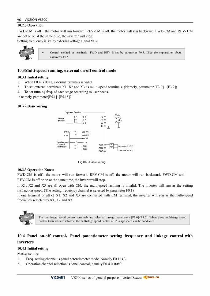
VICSION VS500
VS500 series of general purpose inverter Duxe.ru
9610.2.3 Operation FWD-CM is off,the motor will run forward. REV-CM is off, the motor will run backward. FWD-CM and REV- CM are off or on at the same time, the inverter will stop. Setting frequency is set by external voltage signal VC2
10.3Multi-speed running, external on-off control mode 10.3.1 Initial setting 1. When F0.4 is 00#1, external terminals is valid. 2. To set external terminals X1, X2 and X3 as multi-speed terminals. (Namely, parameter [F3.0] ~[F3.2]) 3. To set running freq. of each stage according to user needs. (namely, parameter[F5.1]~[F5.15])。 10 3.2 Basic wiring 10.3.3 Operation Notes: FWD-CM is off,the motor will run forward. REV-CM is off, the motor will run backward. FWD-CM and REV-CM is off or on at the same time, the inverter will stop. If X1, X2 and X3 are all open with CM, the multi-speed running is invalid. The inverter will run as the setting instruction speed. (The setting frequency channel is selected by parameter F0.1) If one terminal or all of X1, X2 and X3 are connected with CM terminal, the inverter will run as the multi-speed frequency selected by X1, X2 and X3
10.4 Panel on-off control,Panel potentiometer setting frequency and linkage control with inverters 10.4.1 Initial setting Master setting: 1. Freq. setting channel is panel potentiometer mode. Namely F0.1 is 3. 2. Operation channel selection is panel control, namely F0.4 is 00#0.
Control method of terminals FWD and REV is set by parameter F0.5.(See the explanation about parameter F0.5.
M
Motor U
W V
R S T
FWD REV
CM
AO1 AO2
GND
FWD REV
E
Multi-speed Control terminals
X1 X2
X3
× × ×
3-phase Breaker
Power Supply
Voltmeter (0~10V)
Voltmeter (0~10V)
Fig10-3 Basic wiring
The multistage speed control terminals are selected through parameters [F3.0]-[F3.5]. When three multistage speed control terminals are selected, the multistage speed control of 15-stage speed can be conducted

Duxe.ru VICSION VS500
VS500 series of general purpose inverter Duxe.ru
973. Communication setting (Parameter F9.0) is default. 4. If F9.3 is 0001, the inverter is master. Slave setting: 1. Freq. setting channel is RS485 interface. Namely F0.1 is 2. 2. Operation channel selection isRS485 interface. Namely F0.4 is 00#2. 3. Communication setting (Parameter F9.0) is default. 4. If F9.3 is 0000, the inverter is slave. 5. Linkage setting proportion (Parameter F9.5) will be set by user needs. 6. Rectify channel of linkage setting proportion is external voltage signal VC1. Namely F9.6 is 2 10.4.2 Basic wiring 10.4.3 Operation Notes: Running freq. of slave has a certain proportion with master. Linkage setting proportion is set by parameter F10.5. In this example, freq. proportion of master and slaves can get across by VC1 channel
M
Motor U
W V
R S T
E
RS485 +
-
Host
M
Motor U
W V
R S T
RS485 +
-
Guest
M
Motor U
W V
R S T
RS485 +
-
× × ×
× × ×
× × ×
VS
GND
VS
GND VC2
VC2
3-phase Breaker
Power Supply
3-phase Breaker
Power Supply
3-phase Breaker
Power Supply Guest
Fig10-4 Basic wiring

VICSION VS500
VS500 series of general purpose inverter Duxe.ru
9810. 5 Energy-saving reconstruction of escalator (for reference only) 10.5.1 Initial setting 1. Command channel: External control ([F0.4] =###1). 2. Mode of running command: 3-wire mode ([F0.5] =2). 3. 3-wire running control: Select the terminal X3 ([F3.2] =18). 4. Relay output selection: Time of internal timer is up ([F3.8] =11). 5. Internal timer: be set according to the specific circumstance ([F6.0]). 6. Trigger terminal of internal timer: Terminal X4 ([F3.3] =24). 10.5.2 Basic Wiring Diagram: 10.5.3 Operation instructions Under the normal state, when TA and TB are connected, X3 and CM will be naturally connected to form the valid command status. At this time, when there is input signal by infrared induction, FWD terminal will receive the starting signal for running and the inverter will start to run. After running to the time set by parameter [F6.0], TA and TB will output 0.5s disconnection signal and the inverter will stop running. This scheme is used in inductive self-running control of the escalator: the escalator automatically stops when there is no person and logistics (it is used only in the reconstruction of the escalator that can be stopped). 10.6 PLC control of start/Stop and 3-stage speed running of inverter 10.6.1 Introduction of exemplificative control function: One typical control method is hereby provided through one simple routine of PLC control of inverter, to achieve the purpose of integrating the inverter and the system. The control approach is as follows: 1. Start inverter running through X0 terminal; 2. Stop inverter running through X5 terminal; 3. Connect X1, X2, and X3 to separately correspondingly output frequencies 10Hz, 20Hz and 50Hz; 4. When terminals are connected at the same time, the frequency output is invalid (outputting 0 frequency). 10.6.2 System configuration:
Master station: Mitsubishi PLC Model: FX2N-16MR-001 Slave station: E380-4T0220 series inverter
10.6.3 Hardware connection of the master and slave SUNFAR inverter can realize RS485 communication with PLC by connecting with crystal head telephone line, show as follows:
M
motor U
W V
R S T
X3 TA TB
E
Infrared sensor input
(valid while on)
CM
X4 FWD
× × ×
Three phase breaker
CM
Three phase
power supply
Fig. 10-5 Basic Wiring Diagram

Duxe.ru VICSION VS500
VS500 series of general purpose inverter Duxe.ru
99
10.6.4 Wiring Diagram of SUNFAR inverter and PLC Master:
10.6.5 Slave setting: 1. Frequency input channel: communication interface (F0.1=2) 2. Running command channel: communication interface (F0.4=00#2) 3. Communication setting F9.0: defaults 4. Communication auxiliary function configuration F9.3 = 0000: the inverter as slave 10.6.6 Operation description: X0 terminal on, PLC control inverter operation. X1 terminal on, inverter running speed 10Hz. X2 terminal on, inverter running speed 20Hz. X3 terminal on, inverter running speed 50Hz. X5 terminal on, inverter stops.
Fig. 1 Wiring Method
Fig.2 Main Loop Wiring Diagram
+SDARDA RDB SDB SG -
FX2N-485-BD
N
L
COM
X0
X1
X2
X3
X5Stop
Speed3
Speed2
Speed1
Start
FX2N-485-BD
RDA
RDB
R S T
U V W
+
-
M
Three phase grid
E380
FX2N
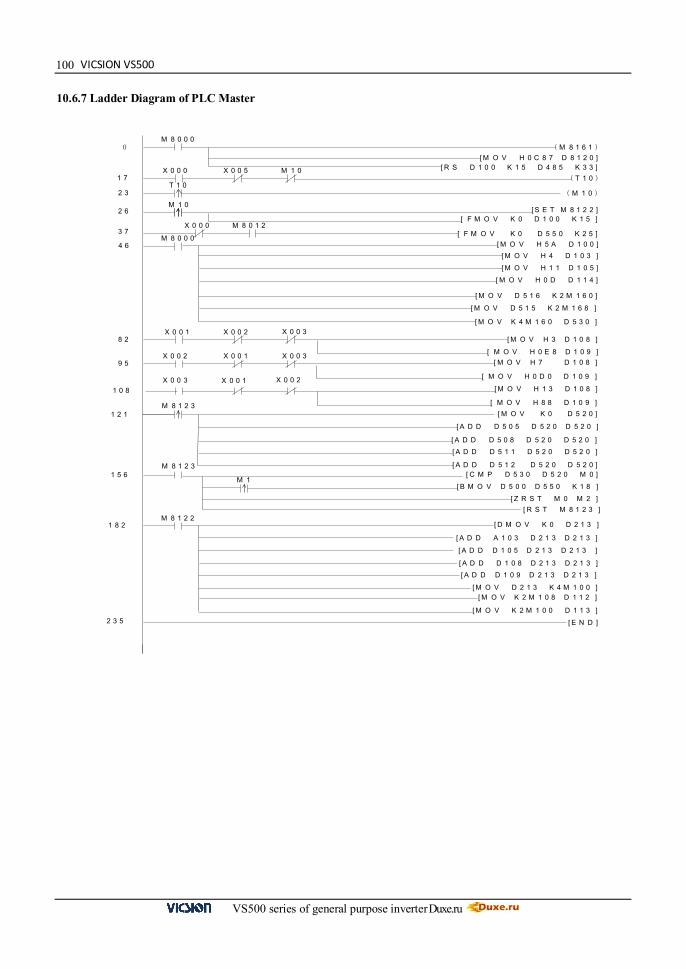
VICSION VS500
VS500 series of general purpose inverter Duxe.ru
100 10.6.7 Ladder Diagram of PLC Master
( M 8 1 6 1 )M 8 0 0 0
[ M O V H 0 C 8 7 D 8 1 2 0 ][ R S D 1 0 0 K 1 5 D 4 8 5 K 3 3 ]
0
X 0 0 0 X 0 0 5 M 1 0 ( T 1 0 )1 7
T 1 0 ( M 1 0 )2 3
2 6 M 1 0
[ S E T M 8 1 2 2 ][ F M O V K 0 D 1 0 0 K 1 5 ]
[ F M O V K 0 D 5 5 0 K 2 5 ]M 8 0 1 2 X 0 0 0
3 7
[ M O V H 1 1 D 1 0 5 ]
[ M O V H 4 D 1 0 3 ]
M 8 0 0 0 [ M O V H 5 A D 1 0 0 ]4 6
[ M O V D 5 1 6 K 2 M 1 6 0 ]
[ M O V H 0 D D 1 1 4 ]
[ M O V D 5 1 5 K 2 M 1 6 8 ]
[ M O V K 4 M 1 6 0 D 5 3 0 ]
8 2 X 0 0 1
[ M O V H 3 D 1 0 8 ]X 0 0 3 X 0 0 2
[ M O V H 0 E 8 D 1 0 9 ]X 0 0 2
[ M O V H 0 D 0 D 1 0 9 ]
X 0 0 1 X 0 0 3 [ M O V H 7 D 1 0 8 ]9 5
[ M O V H 1 3 D 1 0 8 ]
[ M O V H 8 8 D 1 0 9 ]
1 0 8
X 0 0 3 X 0 0 1 X 0 0 2
1 2 1
[ A D D D 5 1 1 D 5 2 0 D 5 2 0 ]
[ A D D D 5 1 2 D 5 2 0 D 5 2 0 ]
[ A D D D 5 0 8 D 5 2 0 D 5 2 0 ]
[ A D D D 5 0 5 D 5 2 0 D 5 2 0 ]
[ M O V K 0 D 5 2 0 ]M 8 1 2 3
1 5 6 M 8 1 2 3
[ Z R S T M 0 M 2 ][ R S T M 8 1 2 3 ]
[ B M O V D 5 0 0 D 5 5 0 K 1 8 ]
[ C M P D 5 3 0 D 5 2 0 M 0 ]M 1
1 8 2
[ M O V K 2 M 1 0 0 D 1 1 3 ]
[ M O V K 2 M 1 0 8 D 1 1 2 ][ M O V D 2 1 3 K 4 M 1 0 0 ]
[ A D D D 1 0 8 D 2 1 3 D 2 1 3 ]
[ A D D D 1 0 9 D 2 1 3 D 2 1 3 ]
[ D M O V K 0 D 2 1 3 ]
[ A D D A 1 0 3 D 2 1 3 D 2 1 3 ]
[ A D D D 1 0 5 D 2 1 3 D 2 1 3 ]
M 8 1 2 2
[ E N D ]2 3 5

Duxe.ru VICSION VS500
VS500 series of general purpose inverter Duxe.ru
101
AppendixⅠMODBUS protocol.
1. Communication Configuration F9.0=X1XX, select MODBUS-RTU protocol. F9.0=X0XX, select SUNFAR self-defined protocol. Notes: X indicates that bit is an arbitrary number.
2. Communication Function To complete the communication between the upper computer and inverter, including sending the operating command to the inverter, setting running frequency, rewriting the function code parameters as well as reading the running status, monitoring parameters, fault information and function code parameters of the inverter
3. Protocol Format MODBUS-RTU Format 4. Protocol Format Explanation 4.1 Slave address 0 is broadcast address, slave address can be set from 1~247. 4.2 PDU part (1) Function code 03: for reading the functional parameters, running status, monitoring parameters and fault information of multiple inverters, which can read maximum 6 address-contiguous inverter parameters. Transmission by the master:
PDU part 03 Register start address, high-order
Register start address, low-order
Number of registers, high-order
Number of registers, low-order
Data length (Byte) 1 1 1 1 1
Response by the slave:
PDU part 03 Number of bytes read (2*number of registers) Content read
Data length (Byte) 1 1 2*number of registers
(2) Function code 06: for rewriting the operating command, running frequency and functional parameters of single inverter. Transmission by the master:
PDU part 06 Register start address, high-order
Register start address, low-order
Register data, high-order
Register data, low-order
Data length (Byte) 1 1 1 1 1
>3.5×Ö·û´«Êä¼ä̧ôʱ¼ä ´Ó»úµØÖ· ¹¦ ÄÜÂë Êý¾Ý CRCУÑé >3.5×Ö·û´«
Êä¼ä̧ôʱ¼ä
Ö¡Æðʼ Ö¡½áÊø
ADU
PDU
>3.5 character transmission interval time
Slave address Function
code Data CRC
calibration
>3.5 character transmission interval time
Frame start Frame end

VICSION VS500
VS500 series of general purpose inverter Duxe.ru
102Response by the slave:
PDU part 06 Register start address, high-order
Register start address, low-order
Register data, high-order
Register data, low-order
Data length (Byte) 1 1 1 1 1
The slave will conduct objection response in case of occurrence of certain error. Objection response:
PDU part 0x80+function code Objection code
Data length (Byte) 1 1
Objection code indicates the error type:
Objection code Error corresponded 01 Illegal function code 02 Illegal data address 03 Data exceeding limit 04 Invalid operation of slave 20 Excessive parameters read 21 Retention and implicit parameters read and written 22 Data modification prohibited during slave running 23 Data modification protected by password
4.3 CRC
CRC CRC low-order CRC high-order Data length (Byte) 1 1
CRC function is as follows: unsigned int crc_chk_value(unsigned char *data_value, unsigned char length) { unsigned int crc_value=0xFFFF; int i; while(length--) { crc_value^=*data_value++; for(i=0;i<8;i++) { if(crc_value&0x0001) crc_value=( crc_value>>1)^0xA001; else crc_value= crc_value>>1; } } return(crc_value); }

Duxe.ru VICSION VS500
VS500 series of general purpose inverter Duxe.ru
1035. Address Definition of Communication Parameters Address distribution of inverter parameters
Register meaning Register address space
Function parameter 1 The high-order is the group-index of the function code, and the low-order is the label of the function code, such as F1.11, and its register address is F10B
Monitoring parameter The high-order is 0xD0, low-order is the label of monitoring, such as d.12, its register address is D00C Given by PID 0x1000
Operating command 2 0x1001 Frequency setting 0x1002 Inverter status 3) 0x2000
Fault information 4) 0x2001 Note: 1) If EEPROM of the function code parameter is frequently written, its service life will be reduced. Some
parameters do not need to be stored under the communication mode, and only the value in RAM needs to be modified. It only needs to change F in the register high address to 0 when writing RAM value of the functional parameter, for example, if needing to write RAM value of F1.11, its register address shall be 010B. However, this register address representation method cannot be used for reading the functional parameter of the inverter.
2) Operating command code corresponding to the operating instruction:
Operating command code Operation command 0x0000 Invalid 0x0001 Forward run to start 0x0002 Reversion run to start 0x0003 Stop 0x0004 Slave forward jog 0x0005 Slave reversion jog 0x0006 Jog run to stop 0x0020 Slave fault reset
3) Inverter status code corresponding to the indication meaning:
Inverter status code Implications
0x0000 Slave DC voltage is not prepared
0x0001 Slave forward running
0x0002 Slave reversion running
0x0003 Slave stop
0x0004 Slave forward jog running
0x0005 Slave reversion jog running
0x0011 Forward accelerating
0x0012 Reversion accelerating
0x0013 Instantaneous stop and restart
0x0014 Forward decelerating
0x0015 Reversion decelerating
0x0016 Slave is under DC braking status
0x0020 Slave is on fault status 4) The high-order of the fault information code is 0, and low-order corresponds to the label of inverter fault code
behind Fu. for example, the fault information code 0x000C means the inverter fault code is Fu.12.

VICSION VS500
VS500 series of general purpose inverter Duxe.ru
1046 Examples 6.1 To start forward running of 1# inverter Master request:
Slave address Function code
Top-bit of register initial
address
Low-bit of register initial
address
Top-bit of register data
Low-bit of register data
Low-bit of CRC
calibration
Top-bit of CRC
calibration
01 06 10 01 00 01 1D 0A
Response by slave: inverter under forward running, return: request the same data with the master 6.2 To set the inverter running frequency to 50.00Hz Master request:
Slave address
Top-bit of register initial
address
Top-bit of register initial
address
Low-bit of register initial
address
Top-bit of register data
Low-bit of register
data
Low-bit of CRC
calibration
Top-bit of CRC
calibration
01 06 10 02 13 88 21 9C
Response by slave: inverter under 50.00Hz running, return: request the same data with the master 6.3 To read the current running frequency and output current of the inverter: Inverter reply frequency of 50.00Hz and output current of 1.1A Master request:
Slave address Function code
Top-bit of register initial
address
Low-bit of register initial
address
Top-bit of register number
Low-bit of register number
Low-bit of CRC
calibration
Top-bit of CRC
calibration
01 03 D0 00 00 02 FC CB
Response by slave:
Slave address Function code Read bytes
Top-bit of 1st register
data
Low-bit of 1st register
data
Top-bit of 2nd register
data
Low-bit of 2nd register
data
Low-bit of CRC
calibration
Top-bit of CRC
calibration
01 03 04 13 88 00 0B 3F 5A

Duxe.ru VICSION VS500
VS500 series of general purpose inverter Duxe.ru
105
AppendixⅡ OPTIONS
1. Operation panel Sometimes users need to take operation panel out of the inverter or control cabinet, if users purchase panel base and wire, it is convenient to install and debug. Wire between operation panel and inverter should be less than 15m. If the length is above 15m, long-distance control line is needed 1.1 Appearance of panel base 1.2 Appearance of small panel base
Fig C-1 Dimension of panel bas Fig C-2 Hole dimension of panel base
Fig C-3 Dimension of small panel base Fig C-4 Hole dimension of small panel base
It is recommended that users take Fig C-4 and Fig-D Hole dimension of panel base

VICSION VS500
VS500 series of general purpose inverter Duxe.ru
1061.3 Installation of panel base Open a hole on the control cabinet according to dimension of panel base. And put the panel horizontally into the hole. Then four locks in panel base will lock. There is an interface on the bottom of base, please insert the long-distance control wire into it, 3. Brake resistance During the running of the inverter, if the speed of the controlled motor drops too fast or the motor load jitters too fast, the motor’s electromotive force, through the inverter, will charge the internal capacitor of the inverter in reverse, thus pumping the voltages of both ends of the power module and easily resulting in damage to the inverter. The internal control of the inverter will suppress such situation according to the load condition; when the brake performance fails to reach requirements of customers, external braking resistor will be required to realize prompt release of energy. External braking resistor belongs to the energy-consumption braking mode, of which the energy will be all dissipated to power braking resistor. Therefore, the selection of power and resistance value of the braking resistor must be reasonable and effective. The following is the introduction of the recommended braking resistor powers and resistance values for partial models of Sunfar inverters. Users can appropriately change the values according to the load condition, but the values shall be within the scope required by Sunfar inverters.
Model Applied motor (KW)
Power of brake resistance (KW)
Brake resistance (Ω) Brake torque
(%) E380-2S0015 1.5 0.4 75 100 E380-2S0022 2.2 0.6 50 100 E380-2S0037 3.7 1 35 100
E380-4T0015G/0022P 1.5 0.5 300 100 E380-4T0022G/0037P 2.2 0.65 200 100 E380-4T0037G/0055P 3.7 1.0 125 100 E380-4T0055G/0075P 5.5 1.5 85 100 E380-4T0075G/0110P 7.5 2.0 65 100 E380-4T0110G/0150P 11 2.5 50 100 E380-4T0150G/0185P 15 3.6 35 100 E380-4T0185G/0220P 18.5 4.5 30 100 E380-4T0220G/0300P 22 5.5 25 100 E380-4T0300G/0370P 30 6.5 20 100 E380-4T0370G/0450P 37 8.5 15 100 E380-4T0450G/0550P 45 12 12 100 E380-4T0550G/0750P 55 15 10 100 E380-4T0750G/0900P 75 18 8 100 E380-4T0900G/1100P 90 18 8 100 E380-4T1100G/1320P 110 25 6 100 E380-4T1320G/1600P 132 30 5 100
E380-4T1600G/1850P 160 36 4 100
E380-4T1850G/2000P 185 42 3.5 100
E380-4T2000G/2200P 200 50 3 100
E380-4T2200G/2500P 220 50 3 100
E380-4T2500G/2800P 250 60 2.5 100
E380-4T2800G/3150P 280 60 2.5 100
E380-4T3150G/3500P 315 75 2 100
E380-4T3500G/4000P 350 75 2 100
E380-4T4000G/4500P 400 90 1.5 100
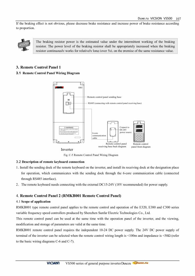
Duxe.ru VICSION VS500
VS500 series of general purpose inverter Duxe.ru
107If the braking effect is not obvious, please decrease brake resistance and increase power of brake resistance according to proportion.
3. Remote Control Panel 1 3.1 Remote Control Panel Wiring Diagram
3.2 Description of remote keyboard connection 1.Install the sending dock of the remote keyboard on the inverter, and install its receiving dock at the designation place
for operation, which communicates with the sending dock through the 6-core communication cable (connected through RS485 interface).
2.The remote keyboard needs connecting with the external DC15-24V (18V recommended) for power supply.
4. Remote Control Panel 2 (RMKB001 Remote Control Panel) 4.1 Scope of application
RMKB001 type remote control panel applies to the remote control and operation of the E320, E380 and C300 series variable frequency speed controllers produced by Shenzhen Sunfar Electric Technologies Co., Ltd.
This remote control panel can be used at the same time with the operation panel of the inverter, and the viewing, modification and storage of parameters are valid at the same time.
RMKB001 remote control panel requires the independent 10-24 DC power supply. The 24V DC power supply of terminal of the inverter can be selected when the remote control wiring length is <100m and impedance is <50Ω (refer
to the basic wiring diagrams C-6 and C-7).
The braking resistor power is the estimated value under the intermittent working of the braking resistor. The power level of the braking resistor shall be appropriately increased when the braking resistor continuously works for relatively long (over 5s), on the premise of the same resistance value.
Fig. C-5 Remote Control Panel Wiring Diagram
Remote control panel front diagram
and operation.
and at least 10min. after disconnecting power.
1.Refer to the instruction manual before installation
3.Do not remove any cover while applying power
4.Securely ground(earth) the equipment.
2.Do not connect AC power to output terminals UVW.
! WARNING
E380
Remote control panel sending base
Remote control panel receiving base back diagram
Inverter
Connect to DC24V power source
RS485 (connecting with remote control panel receiving base)
6-core communication cable

VICSION VS500
VS500 series of general purpose inverter Duxe.ru
108
¼ üÅ ÌË ®¾ §² å× ù
Power GND
± äƵÆ÷RS485
-++24VCM
-++24V-
RS485Power± äƵÆ÷RS485
-++24VCM
4.2 Main Specifications
1. Wiring method: RS485 point to point communication 2. Remote control distance: 1~1000m
3. Power supply: DC10~24V / 250mA RMKB001 remote control panel requires independent DC10~24V power supply, when remote control wire length is
less than 100m, and wire resistance is less than 50Ω, please choose inverter terminal DC24V (Please refer to basic wiring diagram C-6 and C-7).
4.3 Inverter Basic Setting Before using remote control panel, please carefully check parameters as follows: 1. Communication setting: (F9.0 = 0014), baud rate: 9600bps, parity calibration 2. Inverter address: 0 3. Inverter response delay time: less than 10ms. 4. Master - slave mode: slave (F9.3 = 0010) 4.4 Remote control When the inverter requires to be conducted remote start/stop control, please set the “Running command channel” of the
inverter to be “Serial port communication” mode ([F0.4] = ###2); when this mode is selected for the inverter, the external control terminal, and the operation panel of the inverter will lose the control function.
If the operation panel of the inverter requires emergency stop function when the inverter is controlled through the remote control panel, please set “STOP key valid for all control modes” (Running command channel [F0.4] =##12). At
this time, when the inverter is stopped through the “STOP” key on its panel, it is stopped according to the fault mode, displaying “Fu.16”.
Please set the “Select frequency input channel/mode” parameter of the inverter as “RS485 interface” ([F0.1]=2) if requiring to adjust or set frequency with the remote control panel, and then directly adjust the frequency with the UP or
DOWN key of the remote control panel; or, set the frequency through digital setting ([F0.2]) on the remote control panel.
4.5 Basic Wiring Remote control panel has two basic wiring methods, user can choose any one.
Fig. C-7 Wiring Method 2 Fig. C-6 Wiring Method 1
When the wiring length is over 100m, please separately supply power to the remote control panel, and the
24V power supply of the inverter cannot be accessed to.
Inverter Keyboard water-type outlet
Inverter

Duxe.ru VICSION VS500
VS500 series of general purpose inverter Duxe.ru
109
Fig. C-9 Dimension Size: 150.5 * 77.5 mm
Sheet thickness≤1.5mm
Fig. C-8 Product Appearance
4.6 Basic function
RMKB001 remote control panel features most functions of the standard operation panel of the inverter, mainly including:
1) Viewing, modification and storage of parameters Through the remote control panel, all parameters from F0-FC sets can be viewed (except the retention parameters), and
only parameters of F0-F9 sets can be modified. When the parameter modification is locked by the parameter write protection function, only the legal parameters can be
modified. 2) Start/stop control of the inverter
3) Fault display, viewing and resetting 4) Viewing of running parameters
4.7 Operating instructions
The operation method of RMKB001 remote control panel is identical with that of the standard keyboard of the inverter produced by Sunfar, and please refer to the relevant description of any of C320, E380 or C300 series inverter.
4.8 Product Appearance and Dimension Size
Partial parameters cannot be conducted valid upper/lower limit suppression when internal parameters of the inverter
are modified through the remote control panel, and when the data scope exceeds the limit, it will result in failure of the
parameter setting.