prediction of supersonic jet noise from complex nozzles
TRANSCRIPT
Center for Turbulence ResearchAnnual Research Briefs 2011
3
Prediction of supersonic jet noisefrom complex nozzles
By J. W. Nichols, F. E. Ham, S. K. Lele AND P. Moin
1. Motivation and objectives
This project is motivated by the growing need for innovative strategies to reduce thenoise produced by high-performance supersonic aircraft. The aeroacoustic phenomenonof jet noise, intricately connected to the turbulence dynamics in the jet shear layers andin the region downstream of the jet potential core, remains a large component of theoverall noise generated by supersonic aircraft, despite significant scientific investigationas to its cause. While jet noise reducing techniques have some application in the design oftraditional subsonic commercial aircraft, jet noise is a problem especially for supersonicaircraft that are typically powered by low-bypass turbofan engines. The large velocityratio and the presence of shocks in the exhaust plume from low-bypass engines causejet noise to be the dominant component of the overall aircraft noise, and therefore is animportant issue in the design of the next generation of civil supersonic transport.
Jet noise reduction technology also has application in the design of high-performancetactical aircraft. Jet noise is of particular concern on aircraft carriers, where it is neces-sary for deck crew to be in relatively close proximity to the aircraft at takeoff and landing.In such harsh acoustic environments (150 dB), even the most advanced hearing protec-tion cannot provide complete long-term protection from permanent hearing loss (NRAC,2009). Additionally, noise reduction techniques have the potential for significant benefitin regions where communities and airfields serving supersonic aircraft are in close prox-imity. In these increasingly common situations, deployment of effective sound reductiontechnology would minimize complaints and aid in compliance with noise regulations.
Large-eddy simulation (LES) coupled to a Ffowcs Williams-Hawkings (FWH) solverhas emerged as a useful tool for the prediction of jet noise (Bodony & Lele 2008). To inves-tigate jet noise reduction strategies with LES, the need to simulate complex geometriesis clear. Current jet noise reduction techniques include the addition of tabs or chevronsto the nozzle rim (Liu et al. 2009), alteration of the cross-sectional shape of the nozzle(Tam 1998; Tam & Zaman 2000), beveling of the nozzle exit (Viswanathan et al. 2008),and the addition of an array of micro-jets around the nozzle perimeter (Alkislar et al.2007; Shur et al. 2010). In each case, significant three-dimensional structure is added tothe nozzle geometry. Previous approaches to the treatment of 3D geometry include uti-lization of multi-block structured grids (Spalart & Shur 2009), the general grid interface(GGI) technique (Burak et al. 2009), and the immersed boundary method (Du & Morris2011). Unstructured LES, however, is ideally suited to resolving complex geometry withbody-fitted meshes, and for this reason, unstructured finite-element simulations based onthe MILES technique (Liu et al. 2009) have been used previously. The unstructured finitevolume LES solver “CharLES” developed at Cascade Technologies, Inc. takes a differentapproach, however, by introducing numerical stencils based on higher-order polynomialexpansion to limit dissipation. The purpose of this brief is to assess the capability of the

4 J. W. Nichols et al.
(a) (b) (c)
x
yz
φ
θ
x
z
x
y
Figure 1. Rectangular nozzle geometry: (a) 3D view of nozzle exterior; (b) mid-plane crosssection along minor axis; (c) mid-plane cross section along major axis.
CharLES unstructured LES solver for the aeroacoustic prediction of supersonic jets fromcomplex nozzles.
2. Results
In order to demonstrate the capability of fully unstructured LES (coupled to an FWHsolver) to accurately predict the noise produced by jets issuing from nozzles of arbitrar-ily complex geometry, we consider two test cases. For validation purposes, these casescorrespond exactly to actual nozzle geometries used in experimental acoustic testing byJames Bridges et al. at the NASA Glenn Research Center. In particular, we will con-sider underexpanded supersonic jets issuing from a plain rectangular nozzle as well as arectangular nozzle with chevrons.
2.1. Heated rectangular jet
The first test case involves a plain rectangular nozzle of aspect ratio 4:1, shown in Figure1(a). The entire flow in and around the nozzle is simulated, in addition to the jet plumedownstream. The interior surface of the nozzle gradually transforms from a circular crosssection upstream to a rectangular cross section at its exit, while undergoing a complicatedsequence of contractions and expansions as shown in cross sections shown in Figures 1(b)and 1(c). The contractions and expansions in the two cross-stream directions offset oneanother, however, so that the cross-sectional area decreases monotonically from inlet toexit, producing an underexpanded supersonic jet plume downstream.
The 4:1 plain rectangular jet was simulated at both isothermal (setpoint 9020) andheated (setpoint 9050) operating conditions. Both operating conditions used a nozzlepressure ratio (NPR) of P0/P∞ = 3.18, where P0 and P∞ are the stagnation pressuresinside the nozzle and in ambient fluid, respectively. This NPR yields a jet Mach numberMj = uj/cj = 1.4, where uj and cj are the jet velocity and the speed of sound at fullyexpanded conditions within the jet core. The two operating points differed in the nozzletemperature ratio (NTR) T0/T∞ defined in terms of stagnation temperatures inside thenozzle, T0, and in the freestream, T∞. Note that NTR > 1 for the isothermal conditionaccounts for the natural cooling as the flow accelerates from the stagnation condition.For the heated case, the elevated NTR results in a hot jet inside which the speed of soundcj is also elevated. For a constant Mj, this implies that uj is also greater than in theisothermal case. This can be seen by defining an acoustic Mach number Ma = uj/c∞ interms of the free stream speed of sound c∞.
To assess the quality of the LES solutions, each operating condition was simulated
Prediction of supersonic jet noise from complex nozzles 5
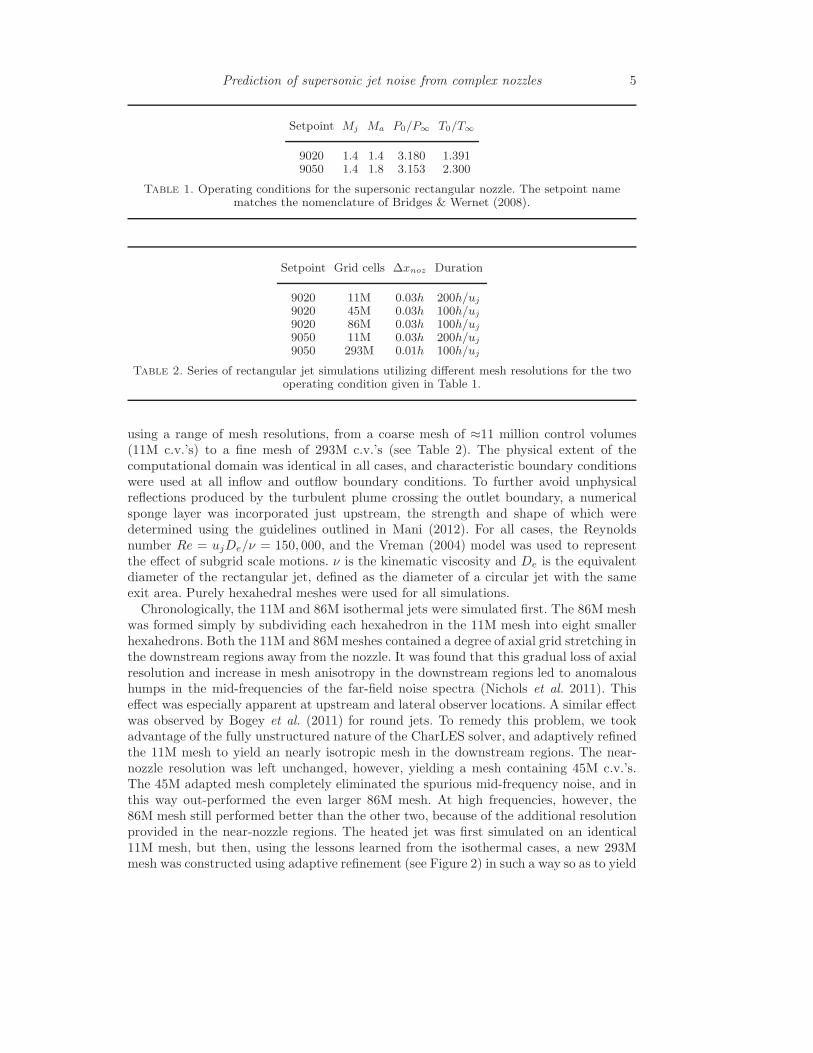
Setpoint Mj Ma P0/P∞ T0/T∞
9020 1.4 1.4 3.180 1.3919050 1.4 1.8 3.153 2.300
Table 1. Operating conditions for the supersonic rectangular nozzle. The setpoint namematches the nomenclature of Bridges & Wernet (2008).
Setpoint Grid cells ∆xnoz Duration
9020 11M 0.03h 200h/uj
9020 45M 0.03h 100h/uj
9020 86M 0.03h 100h/uj
9050 11M 0.03h 200h/uj
9050 293M 0.01h 100h/uj
Table 2. Series of rectangular jet simulations utilizing different mesh resolutions for the twooperating condition given in Table 1.
using a range of mesh resolutions, from a coarse mesh of ≈11 million control volumes(11M c.v.’s) to a fine mesh of 293M c.v.’s (see Table 2). The physical extent of thecomputational domain was identical in all cases, and characteristic boundary conditionswere used at all inflow and outflow boundary conditions. To further avoid unphysicalreflections produced by the turbulent plume crossing the outlet boundary, a numericalsponge layer was incorporated just upstream, the strength and shape of which weredetermined using the guidelines outlined in Mani (2012). For all cases, the Reynoldsnumber Re = ujDe/ν = 150, 000, and the Vreman (2004) model was used to representthe effect of subgrid scale motions. ν is the kinematic viscosity and De is the equivalentdiameter of the rectangular jet, defined as the diameter of a circular jet with the sameexit area. Purely hexahedral meshes were used for all simulations.
Chronologically, the 11M and 86M isothermal jets were simulated first. The 86M meshwas formed simply by subdividing each hexahedron in the 11M mesh into eight smallerhexahedrons. Both the 11M and 86M meshes contained a degree of axial grid stretching inthe downstream regions away from the nozzle. It was found that this gradual loss of axialresolution and increase in mesh anisotropy in the downstream regions led to anomaloushumps in the mid-frequencies of the far-field noise spectra (Nichols et al. 2011). Thiseffect was especially apparent at upstream and lateral observer locations. A similar effectwas observed by Bogey et al. (2011) for round jets. To remedy this problem, we tookadvantage of the fully unstructured nature of the CharLES solver, and adaptively refinedthe 11M mesh to yield an nearly isotropic mesh in the downstream regions. The near-nozzle resolution was left unchanged, however, yielding a mesh containing 45M c.v.’s.The 45M adapted mesh completely eliminated the spurious mid-frequency noise, and inthis way out-performed the even larger 86M mesh. At high frequencies, however, the86M mesh still performed better than the other two, because of the additional resolutionprovided in the near-nozzle regions. The heated jet was first simulated on an identical11M mesh, but then, using the lessons learned from the isothermal cases, a new 293Mmesh was constructed using adaptive refinement (see Figure 2) in such a way so as to yield

6 J. W. Nichols et al.
(a) (b)
Figure 2. Near-nozzle visualization of the meshes used in the (a) 11M and (b) 293M simulations.The 293M mesh was created by adaptively refining the region inside the FWH surface (blue).
downstream isotropy as well as near-nozzle refinement. The isothermal jet simulationshave been presented elsewhere (Nichols et al. 2011), so for the purposes of this brief, wefocus solely upon the heated case.
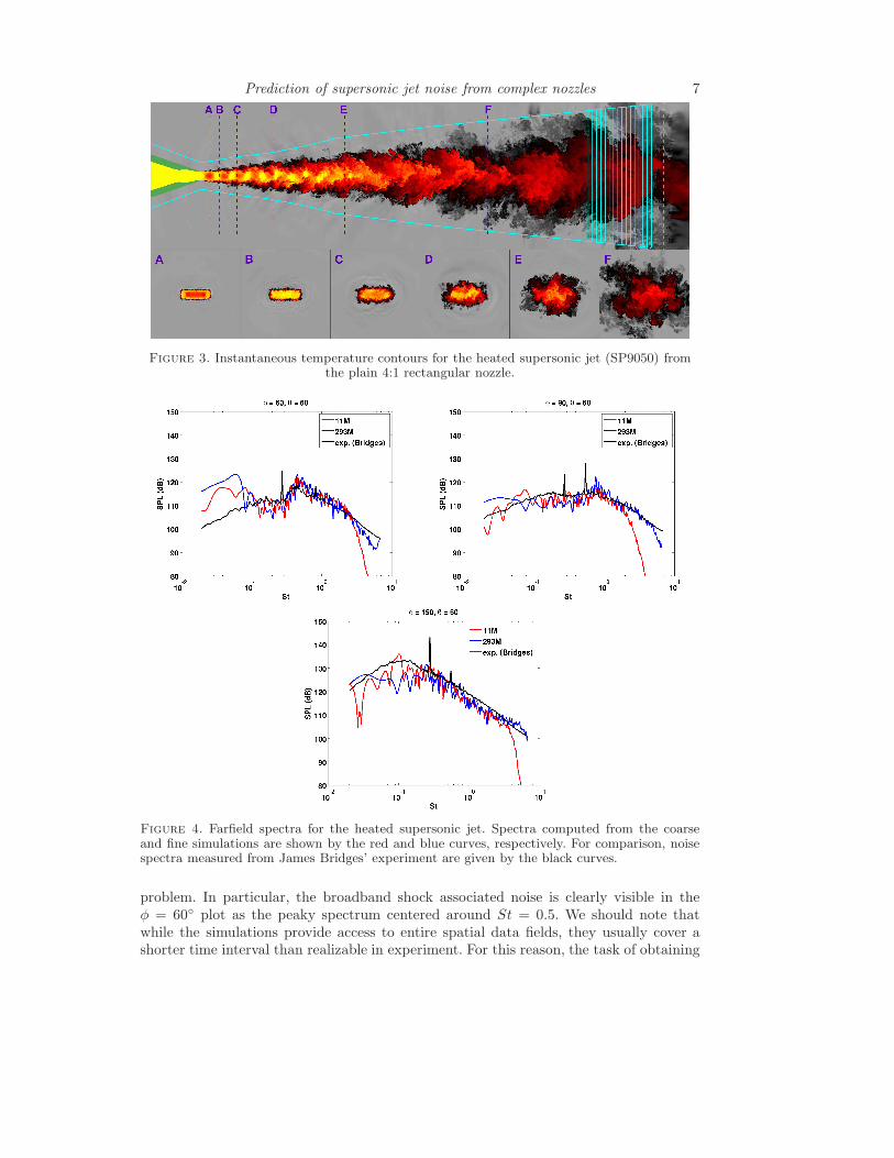
Figure 3 provides a flow visualization of the heated rectangular jet taken from a snap-shot of the 293M mesh simulation. In the top frame, contours of temperature are shownon the y = 0 plane, with gray and yellow indicating the cold and hot extremes, respec-tively. Because the jet is underexpanded as it leaves the nozzle, a train of shock cellsform downstream of the nozzle. In the isothermal jet, these shock cells were observed tooscillate in the z-direction in connection with a strong screech tone. For the heated case,no such oscillatory mode was observed and, as we will see, the screech tone was largelyabsent in this simulation.
Frames (A-F) of Figure 3 show the three-dimensional development of the rectangularjet on a sequence of radial cross sections taken at locations indicated by the correspond-ing labeled vertical dashed lines in the top frame. As noted by Zaman (1996, 1999), aturbulent rectangular jet spreads faster along its minor axis than along its major axis.In this way, the jet gradually transforms from a rectangular cross section to a circularcross section as it evolves downstream.
The solid cyan lines show the location of the FWH surface used for acoustic post-processing. For the post-processing we use a variant of the FWH equation proposedby Spalart & Shur (2009) in which only pressure and velocity are recorded along thesurface, and then the density is computed a posteriori. In heated jets, this allows fora more aggressive placement of the FWH surface with respect to the turbulent regionsbecause pressure is a more uniform function than density. In addition to using the density-substituted FWH variant, we also mitigate the spurious sound produced by vorticitypassing through the surface by averaging over a series of 16 end-caps, following Shuret al. (2005) and Mendez et al. (2009). In Figure 3, the end-caps are represented by thesolid vertical cyan lines. The dashed vertical cyan line indicates the beginning of thesponge layer.
Figure 4 shows the computed farfield spectra for the heated jet. The left panel showsspectra taken at an upstream angle (φ = 60◦), the center panel corresponds to the lateral(φ = 90◦) angle, and the right panel to a downstream angle (φ = 150◦). Here, the angleφ is taken with respect to the upstream jet axis with an origin located at the center pointof the nozzle exit plane. Likewise, θ indicates the azimuthal direction with θ = 0◦ andθ = 90◦ aligned with the narrow and wide dimensions of the nozzle, respectively. In Figure4, the red and blue curves represent the 11M and 293M mesh simulations, respectively,and are compared to experimental measurements (black). As the resolution increases,the spectra align increasingly well with the experimental measurements, suggesting thatthe unstructured LES methodology is indeed capturing all of the relevant physics of the
Prediction of supersonic jet noise from complex nozzles 7
Figure 3. Instantaneous temperature contours for the heated supersonic jet (SP9050) fromthe plain 4:1 rectangular nozzle.
Figure 4. Farfield spectra for the heated supersonic jet. Spectra computed from the coarseand fine simulations are shown by the red and blue curves, respectively. For comparison, noisespectra measured from James Bridges’ experiment are given by the black curves.
problem. In particular, the broadband shock associated noise is clearly visible in theφ = 60◦ plot as the peaky spectrum centered around St = 0.5. We should note thatwhile the simulations provide access to entire spatial data fields, they usually cover ashorter time interval than realizable in experiment. For this reason, the task of obtaining

8 J. W. Nichols et al.
Figure 5. Rectangular nozzle geometry with chevrons, matching that of experimental nozzleNA2C3 developed at the NASA Glenn Research Center.
converged statistics at the low frequency end of the spectrum becomes a challenge forsimulations. The breakdown in convergence at very low frequencies gives rise to thediscrepancies in Figure 4. We expect that these discrepancies may be remedied by runningthe simulations longer, albeit at considerable computational expense.
2.2. Rectangular jet with chevrons
Figure 5 shows the NA2C3 rectangular chevron nozzle developed for experimental testingat the Small Hot Jet Acoustic Rig (SHJAR) facility at the NASA Glenn Research Center.This nozzle was developed as part of the “Extensible Rectangular Nozzle Model System”used to investigate the effects of nozzle aspect ratio, chevrons, and bevels on high-speedjet noise production (Frate & Bridges 2011). This nozzle has aspect ratio 2:1 (no 4:1aspect ratio nozzles were designed with chevrons), and four large chevrons are attachedto each of its long edges. The chevrons arc into the issuing flow and impart significantstreamwise vorticity to it.
For simulation, the precise nozzle geometry was supplied by James Bridges at theNASA Glenn Research Center in the form of a Computer-Aided Design (CAD) file. Thecomputational domain, including the volume inside the nozzle and extending downstreamto a distance of 30 equivalent diameters, was discretized by a series of progressively finemeshes, ranging from 6 million to 262 million control volumes. All of the meshes con-tained purely hexahedral elements, body-fitted to the surface described by the CAD file.As before, the coarse mesh was created first, and then adaptively refined, clustering gridpoints isotropically inside the FWH surface according to Nichols et al. (2011). Character-istic boundary conditions were used at all inflow and outflow boundaries, together witha numerical sponge layer at the outlet.
The operating conditions for the chevron jet simulations performed to date correspondto SP9020 (Table 1). For these cases, the Reynolds number Re ≈ 1.5×10⁶. Like the plainrectangular nozzle, the chevron jet nozzle is also purely convergent, and so produces anunderexpanded jet containing shocks. To capture the effects of these shocks, a hybrid-ENO scheme (Khalighi et al. 2011) was employed with a switch based on the magnitudeof the local dilatation. The high-resolution cases were run as part of a 60 million cpu-hourALCC allocation on the IBM BlueGene/P machine at the Argonne National Laboratory.The CharLES code was found to scale nearly ideally to as many as 65,536 processors.
Figure 6 shows a snapshot of the turbulent flow from the fine scale (263M) simulation.In the top frame, contours of temperature are shown using a white-to-black-to-yellowcolor scale on an axial cross section taken near to one of the nozzle’s lips (not the center

Prediction of supersonic jet noise from complex nozzles 9
Figure 6. Instantaneous temperature contours from the 263M mesh simulation of therectangular chevron nozzle. The nozzle material is shown in green.
(a) (b)
Figure 7. (a) Mean and (b) RMS pressure statistics on a center plane cutting through thenarrow dimension of the chevron nozzle for SP9020.
(a) (b)
Figure 8. Pressure statistics measured along the jet axis for (a) the plain rectangular jet and(b) the rectangular jet with chevrons.
plane). The four chevrons are visible as wedge shapes (the nozzle material is shown ingreen) as they arc through this plane and down into the flow. Radial cross sections areshown in the bottom frames, corresponding to the vertical dashed lines in the top frame.Because the jet is underexpanded, three side jets are propelled outwards between thechevrons along both the upper and lower edges of the nozzle. These side jets merge
10 J. W. Nichols et al.
PSD
(dB
/St)
St
φ = 60◦
10−2 10−1 100 10170
80
90
100
110
120
130
PSD
(dB
/St)
St
φ = 90◦
10−2 10−1 100 10170
80
90
100
110
120
130
PSD
(dB
/St)
St
φ = 120◦
10−2 10−1 100 10170
80
90
100
110
120
130
PSD
(dB
/St)
St
φ = 150◦
10−2 10−1 100 10170
80
90
100
110
120
130
Figure 9. Farfield noise spectra from chevron simulations: 90M LES (blue) and 263M LES(red) compared to experiment (black).
together to form a plus-shaped cross section further downstream, near to the collapseof the potential core. This downstream region is known to be a sensitive region for theproduction of the peak acoustic radiation.
Figure 7 shows that the chevrons affect the near-nozzle jet flow in two ways importantto noise production. In this figure, the mean and RMS pressure statistics are shown on acenter cross section slicing through the narrow dimension of the nozzle. First, the RMSpressure reveals that the side jets enhance turbulent mixing in regions away from thejet axis. Second, the mean pressure field reveals a multitude of shocks in the near-nozzleregion. These shocks are generated at both the chevron tips and the troughs in betweenthem. The net result is that the highly organized shock cells in a plain rectangular jet(Figure 8(a)) are broken up into many small shock cells in the chevron rectangular jet(Figure 8(b)). In this way the chevron jet expands in many small steps instead of in arelatively few large steps.
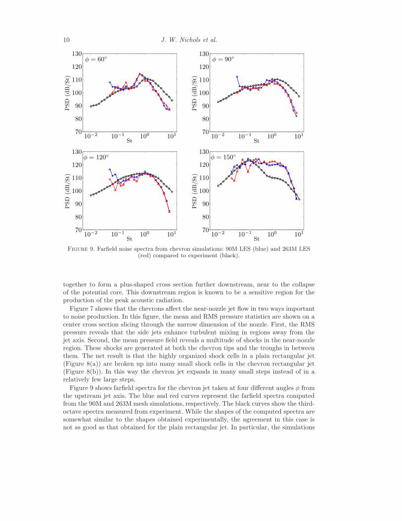
Figure 9 shows farfield spectra for the chevron jet taken at four different angles φ fromthe upstream jet axis. The blue and red curves represent the farfield spectra computedfrom the 90M and 263M mesh simulations, respectively. The black curves show the third-octave spectra measured from experiment. While the shapes of the computed spectra aresomewhat similar to the shapes obtained experimentally, the agreement in this case isnot as good as that obtained for the plain rectangular jet. In particular, the simulations
Prediction of supersonic jet noise from complex nozzles 11
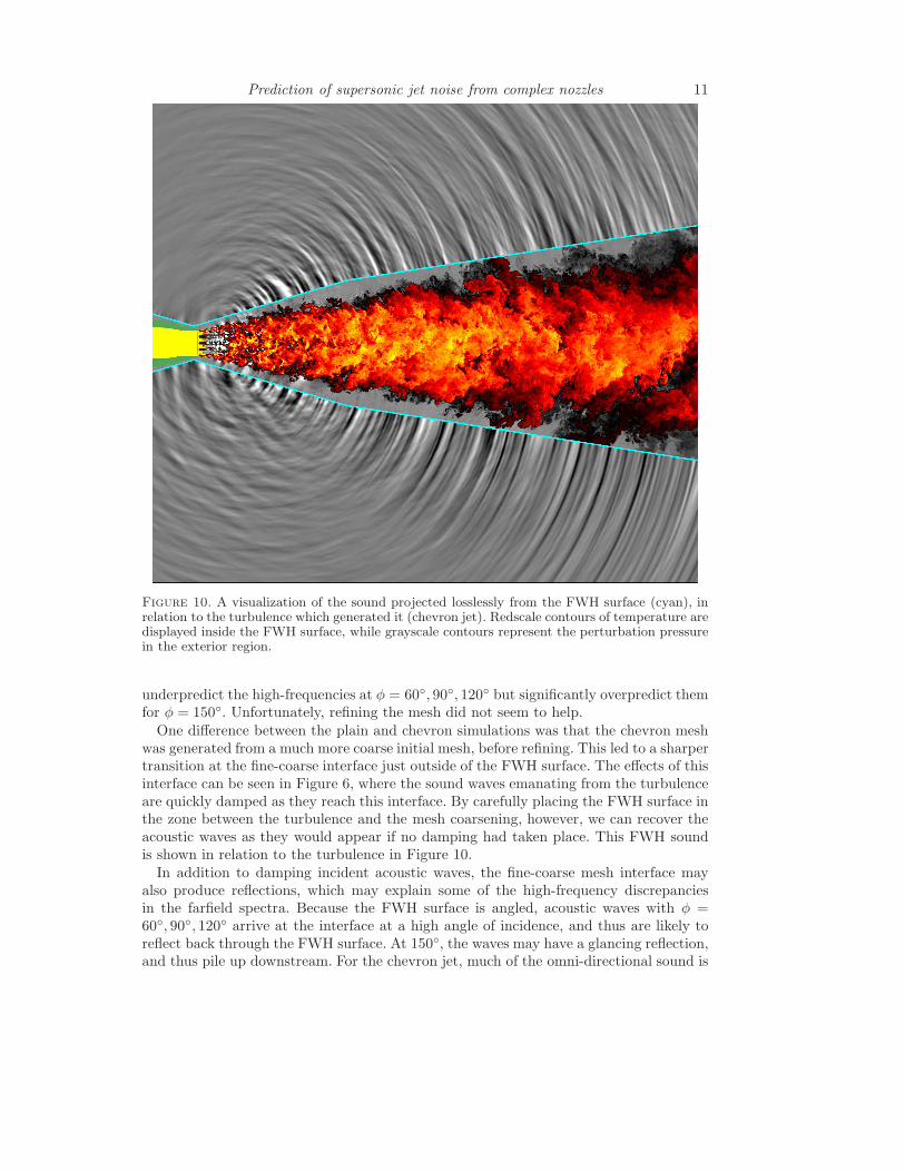
Figure 10. A visualization of the sound projected losslessly from the FWH surface (cyan), inrelation to the turbulence which generated it (chevron jet). Redscale contours of temperature aredisplayed inside the FWH surface, while grayscale contours represent the perturbation pressurein the exterior region.
underpredict the high-frequencies at φ = 60◦, 90◦, 120◦ but significantly overpredict themfor φ = 150◦. Unfortunately, refining the mesh did not seem to help.
One difference between the plain and chevron simulations was that the chevron meshwas generated from a much more coarse initial mesh, before refining. This led to a sharpertransition at the fine-coarse interface just outside of the FWH surface. The effects of thisinterface can be seen in Figure 6, where the sound waves emanating from the turbulenceare quickly damped as they reach this interface. By carefully placing the FWH surface inthe zone between the turbulence and the mesh coarsening, however, we can recover theacoustic waves as they would appear if no damping had taken place. This FWH soundis shown in relation to the turbulence in Figure 10.
In addition to damping incident acoustic waves, the fine-coarse mesh interface mayalso produce reflections, which may explain some of the high-frequency discrepanciesin the farfield spectra. Because the FWH surface is angled, acoustic waves with φ =60◦, 90◦, 120◦ arrive at the interface at a high angle of incidence, and thus are likely toreflect back through the FWH surface. At 150◦, the waves may have a glancing reflection,and thus pile up downstream. For the chevron jet, much of the omni-directional sound is
12 J. W. Nichols et al.
PSD
(dB
/St)
St
10−2 10−1 100 10170
80
90
100
110
120
130
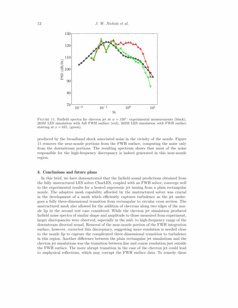
Figure 11. Farfield spectra for chevron jet at φ = 150◦: experimental measurements (black),263M LES simulation with full FWH surface (red), 263M LES simulation with FWH surfacestarting at x = 6De (green).
produced by the broadband shock associated noise in the vicinity of the nozzle. Figure11 removes the near-nozzle portions from the FWH surface, computing the noise onlyfrom the downstream portions. The resulting spectrum shows that most of the noiseresponsible for the high-frequency discrepancy is indeed generated in this near-nozzleregion.
3. Conclusions and future plans
In this brief, we have demonstrated that the farfield sound predictions obtained fromthe fully unstructured LES solver CharLES, coupled with an FWH solver, converge wellto the experimental results for a heated supersonic jet issuing from a plain rectangularnozzle. The adaptive mesh capability afforded by the unstructured solver was crucialin the development of a mesh which efficiently captures turbulence as the jet under-goes a fully three-dimensional transition from rectangular to circular cross section. Theunstructured mesh also allowed for the addition of chevrons along two edges of the noz-zle lip in the second test case considered. While the chevron jet simulation producedfarfield noise spectra of similar shape and amplitude to those measured from experiment,larger discrepancies were observed, especially in the mid- to high-frequency range of thedownstream directed sound. Removal of the near-nozzle portion of the FWH integrationsurface, however, corrected this discrepancy, suggesting more resolution is needed closeto the nozzle lip to capture the complicated three-dimensional transition to turbulencein this region. Another difference between the plain rectangular jet simulations and thechevron jet simulations was the transition between fine and coarse resolution just outsidethe FWH surface. The more abrupt transition in the case of the chevron jet could leadto unphysical reflections, which may corrupt the FWH surface data. To remedy these
Prediction of supersonic jet noise from complex nozzles 13
issues, we have adaptively refined the fine mesh to cluster more grid points close to thenozzle lip, and have applied a strategy to smooth the fine-to-coarse mesh transitions,incorporating several layers of intermediate-sized cells between the two regions. The re-sulting mesh contains 528M c.v’s and is currently running on 131,072 processors of theArgonne BlueGene/P machine, and further results are eagerly awaited.
Acknowledgments
The authors gratefully acknowledge support from NASA grant #NNX07AC94A andfrom the Predictive Science Academic Alliance Program at Stanford University. We arealso grateful to I. Bermejo-Moreno of CTR for his careful reading of a preliminary versionof this manuscript and for his comments which have helped improve it greatly. Computa-tional resources were provided by a DoD Challenge project allocation at the ERDC andAFRL supercomputer centers, and an ALCC computer allocation at Argonne NationalLaboratories.
REFERENCES
Alkislar, M. B., Krothapalli, A. & Butler, G. W. 2007 The effect of streamwisevortices on the aeroacoustics of a mach 0.9 jet. J. Fluid Mechanics 578, 139–169.
Bodony, D. J. & Lele, S. K. 2008 Current status of jet noise predictions using large-eddy simulation. AIAA Journal 46 (2), 364–380.
Bogey, C., Marsden, O. & Bailly, C. 2011 Large-eddy simulation of the flow andacoustic fields of a reynolds number 105 subsonic jet with tripped exit boundarylayers. Physics of Fluids 23, 035104.
Bridges, J. & Wernet, M. 2008 Turbulence associated with broadband shock noisein hot jets. AIAA Paper 2008–2834.
Burak, M. O., Eriksson, L.-E., Munday, D., Gutmark, E. & Prisell, E. 2009Experimental and numerical investigation of a supersonic C-D chevron nozzle. AIAAPaper 2009-4004.
Du, Y. & Morris, P. J. 2011 Noise simulations of supersonic hot jets for chevronnozzles. AIAA Paper 2011-2787.
Frate, F. C. & Bridges, J. E. 2011 Extensible rectangular nozzle model system.AIAA Paper 2011-975.
Khalighi, Y., Nichols, J. W., Bres, G., Ham, F. E., Lele, S. K. & Moin, P.
2011 Unstructured large-eddy simulation for prediction of noise issued from variousnozzles. In Proceedings of the 17th AIAA/CEAS Aeroacoustics Conference.
Liu, J., Kailasanath, K., Ramamurti, R., Munday, D., Gutmark, E. & Lohner,
R. 2009 Large-eddy simulations of a supersonic jet and its near-field acoustic prop-erties. AIAA Journal 47 (8), 1849–1864.
Mani, A. 2012 Analysis and optimization of numerical sponge layers as a nonreflectiveboundary treatment. J. Computational Physics 231 (2), 704–716.
Mendez, S., Shoeybi, M., Sharma, A., Lele, S. K. & Moin, P. 2009 Post-processing of large-eddy simulations for jet noise predictions. Center for TurbulenceResearch Annual Research Briefs pp. 17–31.
Nichols, J. W., Ham, F. E. & Lele, S. K. 2011 High-fidelity large-eddy simulationfor supersonic rectangular jet noise prediction. AIAA Paper 2011-2919.
14 J. W. Nichols et al.
Shur, M. L., Spalart, P. R. & Strelets, M. K. 2005 Noise prediction for increas-ingly complex jets. part i: methods and tests. International Journal of Aeroacoustics4, 213–246.
Shur, M. L., Splart, P. R. & Strelets, M. 2010 LES-based evaluation of a microjetnoise reduction concept in statis and flight conditions. In Proceedings of the IUTAMSymposium on Computational Aero-Acoustics for Aircraft Noise Prediction. ElsevierLtd.
Spalart, P. R. & Shur, M. L. 2009 Variants of the Ffowcs Williams - Hawkingsequation and their coupling with simulations of hot jets. International Journal ofAeroacoustics 8 (5), 477–491.
Tam, C. K. W. 1998 Influence of nozzle geometry on the noise of high-speed jets. AIAAJournal 36 (8), 1396–1400.
Tam, C. K. W. & Zaman, K. B. M. Q. 2000 Subsonic jet noise from nonaxisymmetricand tabbed nozzles. AIAA Journal 38 (4), 592–599.
Viswanathan, K., Shur, M., Spalart, P. R. & Stretlets, M. 2008 Flow andnoise predictions for single and dual-stream beveled nozzles. AIAA Journal 46 (3),601–626.
Vreman, A. W. 2004 An eddy-viscosity subgrid-scale model for turbulent shear flow:Algebraic theory and applications. Physics of Fluids 16, 3670.
Zaman, K. B. M. Q. 1996 Spreading characteristics and thrust of jets from asymmetricnozzles. AIAA Paper 96–0200.
Zaman, K. B. M. Q. 1999 Spreading characteristics of compressible jets from nozzlesof various geometries. J. Fluid Mechanics 383, 197–228.