pozi-loc operators guide - vinten · 4 safety - read this first warning symbols in this operators...
TRANSCRIPT

VintenCamera Control SolutionsO
per
ato
rs G
uid
e Pozi-LocTrip
od
s

VisionPozi-Loc
TripodsPublication Part No. 3770-8 Issue 3
Copyright © Vinten Broadcast Limited 2005
All rights reserved throughout the world. No part of this document may be stored in a retrieval system. transmitted, copied or reproduced in any way including, but not limited to, photocopy, photograph, magnetic or other record without the prior
agreement and permission in writing of Vinten Broadcast Limited.
Vinten and Vision are registered trademarks of Vinten Broadcast Limited.
3
Preface
Thank you and congratulations on your new Pozi-Loc tripod from Vinten
We want you to get the most from your new Pozi-Loc tripod, and therefore encourage you to read this operators guide to familiarise yourself with its many features, some of which may be new to you. It also covers essential health and safety information and a section on maintenance that will ensure you keep your new product in perfect condition.
To receive additional benefits, register with Vinten now, on line by visiting www.vinten.com/regis-ter, or by completing the registration form.
Features and benefits of your new Pozi-Loc tripod
Designed to meet the demands of the professional camera operator, the Pozi-Loc tripod range combines an innovative clamping system with new advances in manufacturing technology. Pozi-Loc tripods are available with aluminium or carbon fibre legs in single-or two-stage configuration and with 75 mm, 100 mm or 150 mm bowl mounting.
• Cam-operated clamping system requires low effort with a 90° turn from on to off, pro-viding the user with a positive indication that the tripod is securely locked.
• The profile of the knob ensures that camera cables cannot snag.
• Lighter than earlier models and with an increased payload capacity of 25kg (55lb).
• Extensive height range and unrivalled torsional stiffness.
Once again, thank you for choosing the Pozi-Loc tripod.
We are confident it will give you many years of reliable performance.

4
Safety - Read This First
Warning Symbols in this Operators Guide
Where there is a risk of personal injury, injury to others, or damage to the tripod or associated equipment, comments appear, highlighted by the word WARN-ING! and supported by the warning triangle symbol.
Technical data
Type
LevellingBowl
Diameter
Maximum Height with Spreader
MinimumHeight with Spreader
RecommendedMaximum Load Weight
TransportLength
3880-3 Two-stageAluminium
150 mm 157.1 cm(61.9 in.)
52 cm (20.5 in.)
45 kg(99 lb)
5.8 kg(12.8 lb)
76 cm(29.9 in.)
3881-3 Two-stageCarbon Fibre
150 mm 157.1 cm(61.9 in.)
52 cm (20.5 in.)
45 kg(99 lb)
5.5 kg(12.1 lb)
76 cm(29.9 in.)
3770-3 Two-stageAluminium
100 mm 156.2 cm(61.5 in.)
41.6 cm(16.4 in.)
25 kg(55 lb)
3.2 kg
(7.1 lb)
71 cm(28.0 in.)
3771-3 Single-stageAluminium
100 mm 145.5 cm
(57.3 in.)
64.7
(25.5 in.)
25 kg(55 lb)
2.8 kg
(6.2 lb)
86.4 cm
(34.0 in.)
3796-3 Single-stageAluminium 2 metre
100 mm 201.5 cm
(79.3 in.)
98.5
(38.8 in.)
25 kg(55 lb)
3.7 kg
(8.1 lb)
115 cm
(45.3 in.)
3883-3 Two-stageAluminium EFP
100 mm 157.1 cm
(61.9 in.)
52 cm
(20.5 in.)
45 kg(99 lb)
5.8 kg(12.8 lb)
76 cm(29.9 in.)
3772-3 Two-stageCarbon Fibre
100 mm 156.2 cm(61.5 in.)
41.6 cm(16.4 in.)
25 kg(55 lb)
2.6 kg
(5.7 lb)
71 cm(28.0 in.)
3773-3 Single-stageCarbon Fibre
100 mm 145.5 cm
(57.3 in.)
64.7
(25.5 in.)
25 kg(55 lb)
2.3 kg
(5.0 lb)
86.4 cm
(34.0 in.)
3884-3 Two-stageCarbon Fibre EFP
100 mm 157.1 cm
(61.9 in.)
52 cm
(20.5 in.)
45 kg(99 lb)
5.5 kg(12.1 lb)
76 cm(29.9 in.)
3774-3 Two-stageAluminium
75 mm 156.2 cm(61.5 in.)
41.6 cm(16.4 in.)
25 kg(55 lb)
3.2 kg
(7.0 lb)
71 cm(28.0 in.)

5
Further informationFor full details on maintenance and spare parts, please refer to Vision Pozi-Loc Tripods - Spares and Repairs (Publication Part No. 3770-9) This is obtainable from Vinten Broadcast Limited or your local Vinten distributor. For information on-line, visit our website at
www.vinten.com.
3775-3 Single-stageAluminium
75 mm 145.5 cm
(57.3 in.)
64.7
(25.5 in.)
25 kg(55 lb)
2.8 kg
(6.2 lb)
86.4 cm
(34.0 in.)
3776-3 Two-stageCarbon Fibre
75 mm 156.2 cm(61.5 in.)
41.6 cm(16.4 in.)
25 kg(55 lb)
2.6 kg(5.64 lb)
71 cm(28.0 in.)
3777-3 Single-stageCarbon Fibre
75 mm 145.5 cm
(57.3 in.)
64.7
(25.5 in.)
25 kg(55 lb)
2.3 kg
(5.0 lb)
86.4 cm
(34.0 in.)
3882-3 Two-stageBaby-Legs
150 mm 50 cm
(19.7 in.)
28 cm
(11 in.)
45 kg(99 lb)
4 kg
(8.8 lb)
36.3 cm
(14.3 in.)
3778-3 Two-stageBaby-Legs
100 mm 51 cm
(20.1 in.)
23.7 cm
(9.3 in.)
25 kg(55 lb)
2.1 kg
(4.6 lb)
32.7 cm
(12.9 in.)
3779-3 Two-stageBaby-Legs
75 mm 51 cm
(20.1 in.)
23.7 cm
(9.3 in.)
25 kg(55 lb)
2.1 kg
(4.6 lb)
32.7 cm
(12.9 in.)
Technical data
Type
LevellingBowl
Diameter
Maximum Height with Spreader
MinimumHeight with Spreader
RecommendedMaximum Load Weight
TransportLength
6
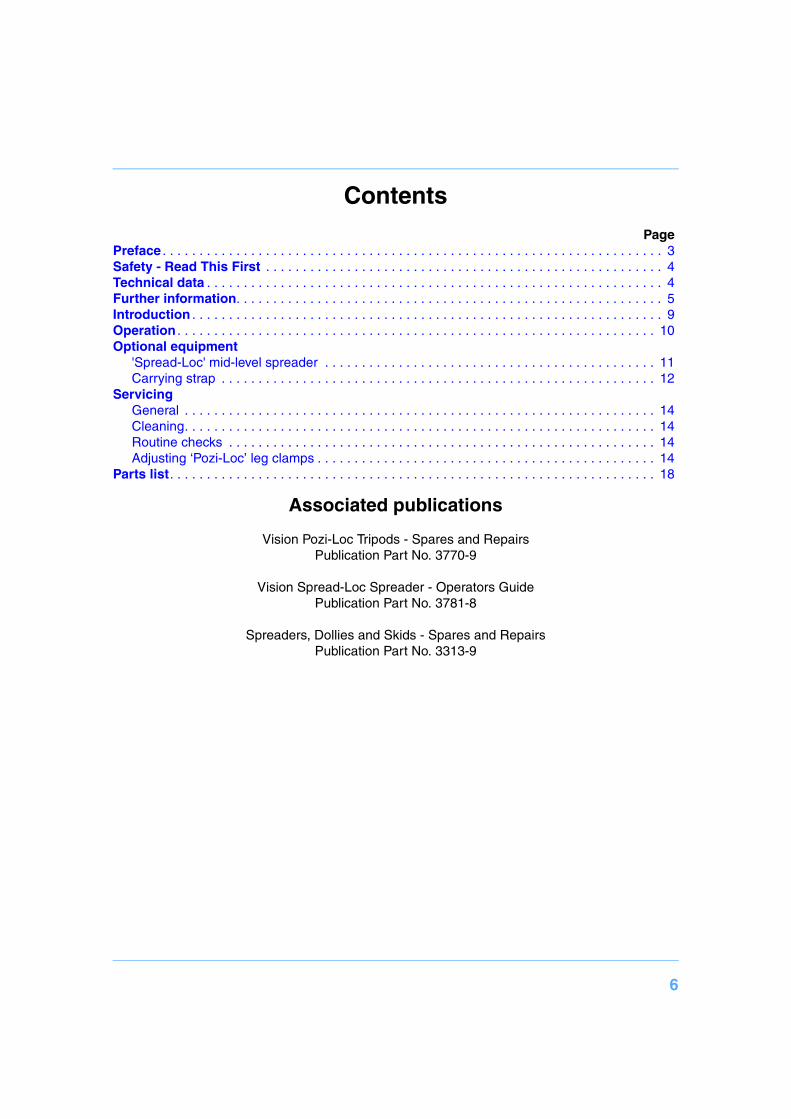
ContentsPage
Preface . . . . . . . . . . . . . . . . . . . . . . . . . . . . . . . . . . . . . . . . . . . . . . . . . . . . . . . . . . . . . . . . . . . . 3Safety - Read This First . . . . . . . . . . . . . . . . . . . . . . . . . . . . . . . . . . . . . . . . . . . . . . . . . . . . . . 4Technical data . . . . . . . . . . . . . . . . . . . . . . . . . . . . . . . . . . . . . . . . . . . . . . . . . . . . . . . . . . . . . . 4Further information. . . . . . . . . . . . . . . . . . . . . . . . . . . . . . . . . . . . . . . . . . . . . . . . . . . . . . . . . . 5Introduction . . . . . . . . . . . . . . . . . . . . . . . . . . . . . . . . . . . . . . . . . . . . . . . . . . . . . . . . . . . . . . . . 9Operation . . . . . . . . . . . . . . . . . . . . . . . . . . . . . . . . . . . . . . . . . . . . . . . . . . . . . . . . . . . . . . . . . 10Optional equipment
'Spread-Loc' mid-level spreader . . . . . . . . . . . . . . . . . . . . . . . . . . . . . . . . . . . . . . . . . . . . . 11Carrying strap . . . . . . . . . . . . . . . . . . . . . . . . . . . . . . . . . . . . . . . . . . . . . . . . . . . . . . . . . . . 12
ServicingGeneral . . . . . . . . . . . . . . . . . . . . . . . . . . . . . . . . . . . . . . . . . . . . . . . . . . . . . . . . . . . . . . . . 14Cleaning. . . . . . . . . . . . . . . . . . . . . . . . . . . . . . . . . . . . . . . . . . . . . . . . . . . . . . . . . . . . . . . . 14Routine checks . . . . . . . . . . . . . . . . . . . . . . . . . . . . . . . . . . . . . . . . . . . . . . . . . . . . . . . . . . 14Adjusting ‘Pozi-Loc’ leg clamps . . . . . . . . . . . . . . . . . . . . . . . . . . . . . . . . . . . . . . . . . . . . . . 14
Parts list. . . . . . . . . . . . . . . . . . . . . . . . . . . . . . . . . . . . . . . . . . . . . . . . . . . . . . . . . . . . . . . . . . 18
Associated publications
Vision Pozi-Loc Tripods - Spares and RepairsPublication Part No. 3770-9
Vision Spread-Loc Spreader - Operators GuidePublication Part No. 3781-8
Spreaders, Dollies and Skids - Spares and RepairsPublication Part No. 3313-9

7
(1) Tripod bowl
(2) Clamp knob
(3) Floor spreader
(4) Floor spreader adjuster
(5) Leg tie strap
(6) Spread-Loc attachment point
(7) Tie down hook
Typical Vision Pozi-Loc Tripod
(1)
(2)
(3)
(6)
(5)
(7)
(4)

8
(1) Tripod bowl
(2) Clamp knob
(7) Tie down hook
(8) Cleat rope spreader
Typical Vision Pozi-Loc Baby-Legs Tripod
(1)
(2)
(8)
(7)

9
IntroductionThe Vision Pozi-Loc range includes single- and two-stage tripods with either aluminium or carbon fibre legs, fitted with 75 mm, 100 mm or 150 mm levelling bowls (See table on page 4). All are fitted with the highly-efficient Pozi-Loc leg clamp, which provides quick set-up and easy adjust-ment.
The tripods are designed for use with Vinten floor spreaders and dollies. An optional mid-level spreader may be used.
Low-level ‘baby-legs’ versions are also available, fitted with a simple cleat rope spreader.

10
Operation
Lift the complete tripod and head out of the case using the finger holes just below the top clamps.
Set the pan bar.
Release the leg tie strap (5).
Still holding the finger holes, open out the legs. Gentle foot or hand pressure on the spreader (3) will ensure that the legs are fully spread.
Adjust the operating height by undoing the leg clamps (2) and pulling the tripod up to the desired height. Adjust the spreader (4) if necessary. Level the head using the level bubble.
Tighten the clamps (2) until an audible click is heard and the knob is in the horizontal, locked po-sition.
In the case of a ‘baby-legs’ tripod, tighten the cleat rope spreader (8).
NOTE: The following procedures refer to a two-stage tripod fitted with a Vision head and a floor spreader. The procedure for single-stage tripods is essentially similar. When using a two-stage tripod the bottom stages should be fully extended or fully retracted, unless conditions such as split levels prevent this.
NOTE: Keep the spreader attached to the tripod
NOTE: Always use the spreader where possible as this increases rigidity of the tripod. Being flexible, the spreader compensates for uneven ground. It can be removed and a dolly fitted. At the fullest extension of the spreader and with all legs fully retracted, the tripod can be used at its lowest operating height. Although the tripod can be set up lower than this without the spreader, it is NOT recommended as the tripod geometry becomes unstable
NOTE: An optional, conventional floor spreader (3379-3) is available for the ‘baby-legs’ tripods.
WARNING! It is possible to set the tripod legs so that the centre-of-gravity of the tilted payload falls outside the footprint of the tripod, lead-ing to instability. Use a mid-level or floor spreader to ensure that the tripod legs are spread sufficiently so that the centre-of-gravity of the tilted payload remains within the footprint of the tripod. Secure the tripod with the tie-down hook (7) or hang a suitable weight from the hook.
NOTE: The Vision spreader protects floors and carpets as well as preventing the tripod legs sinking into soft ground and should be used at all times.If the floor spreader cannot be used, use Vision carpet feet and a ‘Spread-Loc’ mid-level spreader.

11
Optional equipment
'Spread-Loc' mid-level spreader To install the spreader:
Grip the ends of each spreader arm in turn between thumb and fore-finger and press in the attachment release buttons (9).
Push the arm into the tripod attachment (6) until the release engages.
Fit the carpet feet (10).
To remove the spreader, press in the attachment release buttons (9) and free each arm in turn.
Spread-Loc' mid-level spreader
(9)(6)
(10)

12
Carrying strapA carrying strap is available as an optional accessory and is installed as follows:
150 mm bowl tripods
On the underside of the tripod bowl, identify the M6 tapped hole (18).
Position the bowl strap anchor (17) on the underside of the tripod bowl, ensuring it is cor-rectly oriented. Using Loctite 221, secure the bowl strap anchor with the 25 mm M6 screw (16) supplied with the strap.
On the lower moulding of the corresponding leg, drive in the 'knock-out' (15) using a suitable tool. If possible, remove the blank from inside the moulding to prevent subsequent rattle.
Push a blind captive nut (14) into the hole in the lower moulding.
Using a suitable M5 screw, fully compress the blind captive nut. Remove the M5 screw.
Install a washer (13) on the lower strap anchor (12) and screw into the captive nut (14). En-sure that the hole in the strap anchor is oriented so that the karabiner (11.1) can be attached
Using the karabiners (11.1), clip the strap (11) to the strap anchors and adjust to length.
75 mm and 100 mm bowl tripods
On the lower moulding of the leg with the strap (5), drive in the 'knock-out' (15) using a suit-able tool. If possible, remove the blank from inside the moulding to prevent subsequent rat-tle.
Push a blind captive nut (14) into the hole in the lower moulding.
Using a suitable M5 screw, fully compress the blind captive nut. Remove the M5 screw.
Install a washer (13) on the lower strap anchor (12) and screw into the captive nut (14). En-sure that the hole in the strap anchor is oriented so that the karabiner (11.1) can be attached
On the underside of the tripod bowl, remove and discard the screw (16) securing the corre-sponding leg clamp (20). Do not remove the washer (19).
Position the bowl strap anchor (17) on the leg clamp, ensuring it is correctly oriented. Using Loctite 221, secure the bowl strap anchor with the 25 mm M6 screw (16) supplied with the strap. Tighten screw to a torque of 4.5 Nm (40 lbf in.).
Using the karabiners (11.1), clip the strap (11) to the strap anchors and adjust to length.

13
Carrying strap
(13)
(12)
(17)
(11)
(14)
(16)
(15)
(16)
(17)
(19)
(18)
(11.1)
(11.1)
(11.1)
(20)
150 mm
75/100 mm
14
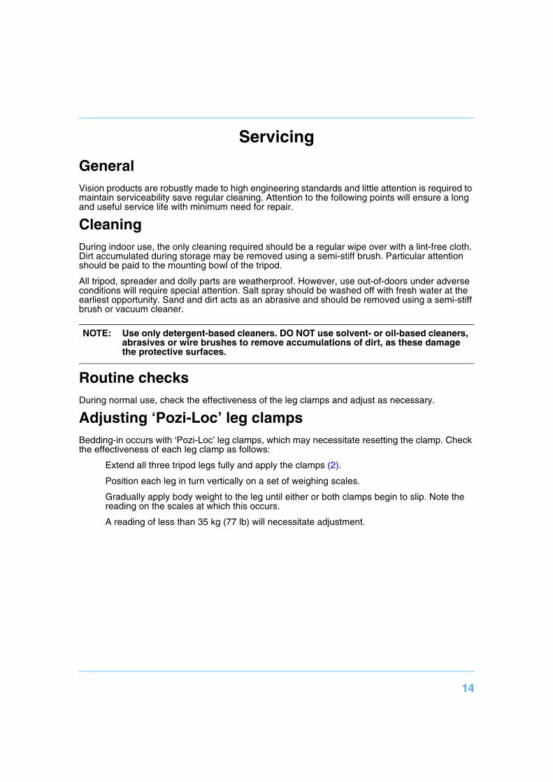
Servicing
GeneralVision products are robustly made to high engineering standards and little attention is required to maintain serviceability save regular cleaning. Attention to the following points will ensure a long and useful service life with minimum need for repair.
CleaningDuring indoor use, the only cleaning required should be a regular wipe over with a lint-free cloth. Dirt accumulated during storage may be removed using a semi-stiff brush. Particular attention should be paid to the mounting bowl of the tripod.
All tripod, spreader and dolly parts are weatherproof. However, use out-of-doors under adverse conditions will require special attention. Salt spray should be washed off with fresh water at the earliest opportunity. Sand and dirt acts as an abrasive and should be removed using a semi-stiff brush or vacuum cleaner.
Routine checksDuring normal use, check the effectiveness of the leg clamps and adjust as necessary.
Adjusting ‘Pozi-Loc’ leg clamps Bedding-in occurs with ‘Pozi-Loc’ leg clamps, which may necessitate resetting the clamp. Check the effectiveness of each leg clamp as follows:
Extend all three tripod legs fully and apply the clamps (2).
Position each leg in turn vertically on a set of weighing scales.
Gradually apply body weight to the leg until either or both clamps begin to slip. Note the reading on the scales at which this occurs.
A reading of less than 35 kg (77 lb) will necessitate adjustment.
NOTE: Use only detergent-based cleaners. DO NOT use solvent- or oil-based cleaners, abrasives or wire brushes to remove accumulations of dirt, as these damage the protective surfaces.
15
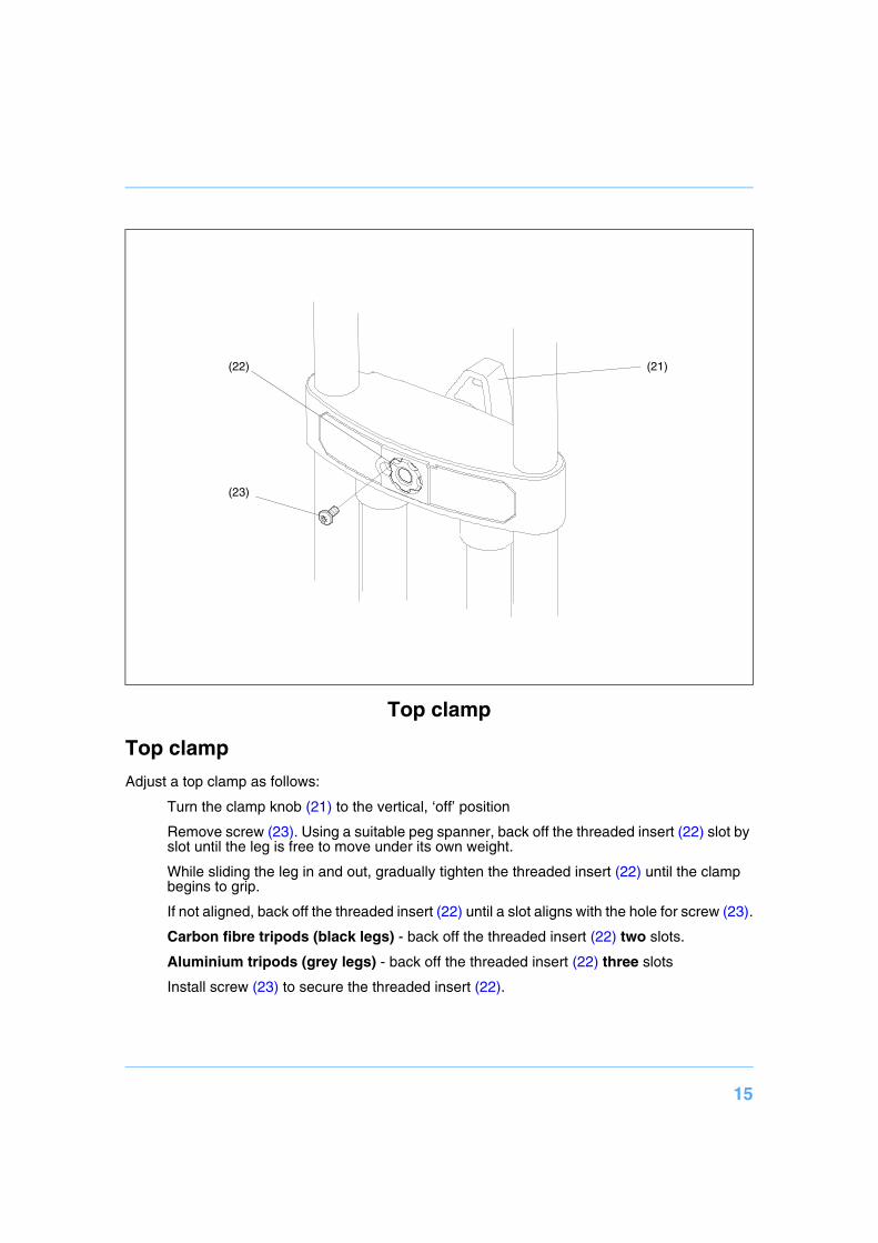
Top clamp
Adjust a top clamp as follows:
Turn the clamp knob (21) to the vertical, ‘off’ position
Remove screw (23). Using a suitable peg spanner, back off the threaded insert (22) slot by slot until the leg is free to move under its own weight.
While sliding the leg in and out, gradually tighten the threaded insert (22) until the clamp begins to grip.
If not aligned, back off the threaded insert (22) until a slot aligns with the hole for screw (23).
Carbon fibre tripods (black legs) - back off the threaded insert (22) two slots.
Aluminium tripods (grey legs) - back off the threaded insert (22) three slots
Install screw (23) to secure the threaded insert (22).
Top clamp
(23)
(22) (21)

16
Bottom clamp
Adjust a bottom clamp as follows:
Tighten the clamp (26) until an audible click is heard and the knob is in the locked position (Position 1).
Using a suitable instrument, such as a flat-bladed screwdriver, carefully remove the knob cap (29).
Remove the retaining screw (28) and washer (27), and pull off the clamp knob (26).
Examine the shaft (24). If there is an identifying groove (24.1) on the shaft, proceed as fol-lows. Otherwise, consult Vision Pozi-Loc Tripods - Spares and Repairs (Publication Part No. 3770-9) or contact your local Vinten dealer.
Replace the clamp knob (26) and turn it to Position 2.
Using a 2.5 mm hexagonal wrench, slacken the grubscrew (24) until the leg is free to move under its own weight.
Bottom clamp
(24)
(24.1)
(26)
(27)
(28)
(29)
(25)
PO
SITI
ON
2
POSITION 1
90°
(24)
(26)

17
With the knob still in Position 2, slide the leg in and out and gradually tighten the grubscrew (24) until the clamp begins to grip.
Back off the grubscrew (24) by a quarter-turn (90°).
Secure the clamp knob (26) with the washer (27) and retaining screw (28). Refit the knob cap (29).

18
Parts listThe following lists include main assemblies and optional accessories. For further information re-garding repair or spare parts, please contact Vinten Broadcast Ltd or your local distributor.
For information on-line, visit our website at
www.vinten.com.
Tripods
Two-stage tripod, aluminium legs, 150 mm bowl 3880-3
Two-stage tripod, carbon fibre legs, 150 mm bowl 3881-3
Two-stage tripod, aluminium legs, 100 mm bowl 3770-3
Single-stage tripod, aluminium legs, 100 mm bowl 3771-3
Single-stage tripod, 2 metre, aluminium legs, 100 mm bowl 3796-3
Two-stage EFP tripod, aluminium legs, 100 mm bowl 3883-3
Two-stage tripod, carbon fibre legs, 100 mm bowl 3772-3
Single-stage tripod, carbon fibre legs, 100 mm bowl 3773-3
Two-stage EFP tripod, carbon fibre legs, 100 mm bowl 3884-3
Two-stage tripod, aluminium legs, 75 mm bowl 3774-3
Single-stage tripod, aluminium legs, 75 mm bowl 3775-3
Two-stage tripod, carbon fibre legs, 75 mm bowl 3776-3
Single-stage tripod, carbon fibre legs, 75 mm bowl 3777-3
Two-stage baby-legs tripod, aluminium legs, 150 mm bowl 3882-3
Two-stage baby-legs tripod, aluminium legs, 100 mm bowl 3778-3
Two-stage baby-legs tripod, aluminium legs, 75 mm bowl 3779-3
Floor spreaders
Floor spreader, for tripods with aluminium legs 3313-3
Floor spreader, for tripods with carbon fibre legs 3363-3
Floor spreader, for Vision 3 systems 3394-3
Floor spreader, for baby-legs tripods 3379-3
Mid-level spreader
‘Spread-Loc’ mid-level spreader 3781-3
Set of three feet (for use with mid-level spreaders) 3378-902SP

19
Dollies
ENG (OB) dolly 3319-3B
ENG (Studio) dolly 3319-3C
ENG (OB) dolly - small 3319-3ST
EFP (OB) dolly 3497-3E
EFP (Studio) dolly 3497-3G
Optional accessories
Carrying strap 3425-3P