power team pq120 manual
TRANSCRIPT
8/14/2019 Power Team PQ120 Manual
http://slidepdf.com/reader/full/power-team-pq120-manual 1/10
ELECTRIC
TWO-STAGE HYDRAULIC PUMP
Read and carefully follow these instructions. Most problems with new equipment are caused by improper operation
or installation. Warning statements must be carefully observed to help prevent personal injury.
SAFETY PRECAUTIONS
WARNING: To help avoid personal injury,
Hydraulic Hose
Before operating the pump, all hose connections must be tightened with the proper tools. Do not
overtighten. Connections should only be tightened securely and leak-free. Overtightening can causepremature thread failure or high pressure fittings to split at pressures lower than their rated capacities.
• Should a hydraulic hose ever rupture, burst, or need to be disconnected, immediately shut off the pump
and shift the control valve twice to release all pressure. Never attempt to grasp a leaking pressurizedhose with your hands. The force of escaping hydraulic fluid could cause serious injury.
• Do not subject the hose to potential hazard such as fire, sharp surfaces, extreme heat or cold, or heavy
impact. Do not allow the hose to kink, twist, curl, or bend so tightly that the oil flow within the hose is
blocked or reduced. Periodically inspect the hose for wear because any of these conditions can damagethe hose and result in personal injury.
• Do not use the hose to move attached equipment. Stress may damage the hose and cause persona
injury.
• Hose material and coupler seals must be compatible with the hydraulic fluid used. Hoses also must not
come in contact with corrosive materials such as creosote-impregnated objects and some paints.Consult the manufacturer before painting a hose. Never paint the couplers. Hose deterioration due to
corrosive materials can result in personal injury.
Pump
• Do not exceed the PSI hydraulic pressure rating noted on the pump nameplate or tamper with the interna
high pressure relief valve. Creating pressure beyond rated capacities can result in personal injury.
• Before replenishing the oil level, retract the system to prevent overfilling the pump reservoir. An overfilcan cause personal injury due to excess reservoir pressure created when cylinders are retracted.
Cylinder
• Do not exceed rated capacities of the cylinders. Excess pressure can result in personal injury.
• Do not set poorly-balanced or off-center loads on a cylinder. The load can tip and cause personal injury.
Form No. 102337
OperatingInstructions for:
PQ120 Series
Sheet No. 1 of 5
Rev. Date: 15 Dec. 1994
© SPX Corporation
Tech. Services: (800) 477-8326 Fax: (800) 765-8326
Order Entry: (800) 541-1418Fax: (800) 288-7031
SPX Corporation5885 11th Street Rockford, IL 61109-3699 USA
Internet Address:http://www.powerteam.com
®
8/14/2019 Power Team PQ120 Manual
http://slidepdf.com/reader/full/power-team-pq120-manual 2/10
Operating Instructions, Form No. 102337, Back sheet 1 of 5
WARNING Continued
Power Supply (Electric)
• Do not use an ungrounded (two-prong) extension cord with this unit.
• Avoid any condition that could create an electrical hazard.
• Any electrical work must be done by a qualified electrician.
• If the power cord is damaged or wiring is exposed, replace or repair immediately.
• Changing the voltage on jet motors is a complicated and, if not done correctly, dangerous procedure.
Consult the manufacturer for specific information before attempting any rewiring. Rewiring voids CSA
approval.
• Disconnect the power supply before removing the electrical box cover or performing repairs or
maintenance.
• All voltages must be wired for CCW rotation when viewed from the lead end (top) of the motor.
• The line voltage must be the same as the voltage for which the pump is wired. (Ex: 110/115 volt pump
plugged into 110/115 volt power source.)
• Check the total amperage draw for the electrical circuit you will be using. (Ex: Do not plug a motor or
motors that may draw 25 amps into a 20 amp fused electrical circuit.)
• Do not attempt to increase the power line capacity by replacing a fuse with another fuse of higher value.
Overheating of the power line and the possibility of a fire can result.• To rewire a motor from one voltage to another, or to change the type of flow control valve (manual or
solenoid), consult the electrical schematic section in the Parts List #100353.
OPERATING PROCEDURE
Filling the Reservoir
NOTE: This pump has been shipped without oil in the reservoir. A high grade hydraulic oil has been shippedwith the pump, but if additional oil is required, use only Power Team hydraulic fluids.
1. Clean the area around the filler cap to remove all dust and grit. Any foreign material in the oil can damage thepolished surfaces and precision-fit components of this pump.
2. Retract all cylinders to the return position.
3. Remove the filler cap, and insert a clean funnel with a filter. Fill the reservoir with hydraulic oil to within 1" of thecover plate. Replace the filler cap.
4. Cycle the pump (with the cylinders attached) several times. Retract the cylinders, and check the oil level in the
pump reservoir.
Hydraulic Connections
1. Clean all the areas around the oil ports of the pump and cylinder.
2. Inspect all threads and fittings for signs of wear or damage, and replace as needed.
3. Clean all hose ends, couplers, or union ends.
4. Remove the thread protectors from the hydraulic oil outlets.
5. Connect the hose assembly to the hydraulic oil outlet, and couple the hose to the cylinder. NOTE: Seal all
hydraulic connections with a high grade, non-hardening thread sealant, such as Power Team HTS6. Teflontape can be used to seal hydraulic connections if only one layer of tape is used. Apply carefully, two threads back,to prevent the tape from being pinched by the coupler and broken off inside the pipe end. Any loose pieces of tape
could travel through the system and obstruct the flow of oil or cause jamming of precision fit par ts.

8/14/2019 Power Team PQ120 Manual
http://slidepdf.com/reader/full/power-team-pq120-manual 3/10
Operating Instructions Form No. 102337
Electrical Connections
WARNING
• To help avoid personal injury, all electrical work must be done by a qualified electrician.
• Disconnect the power supply before removing the electrical box cover.
• All voltages must be wired for counterclockwise (CCW) rotation viewed from the lead end of the motor.
Sheet No. 2 of 5
Rev. Date: 15 Dec. 1994
WARNINGTo help avoid personal injury, all electricalwork must be done by a qualified electrician.
Conductors North American InternationalLine............................Black...................Brown
Neutral.......................White ..................BlueGround ......................Green ..................Green/Yellow
North American & International Color Codes
1. This pump has been assembled with a three-phase 60 cycle motor that can be wired for 230 or 460 volts. Thepump is wired at the factory for 460 volts and is not supplied with a power cord or plug. This pump may also be
ordered with a 50 cycle, 220 or 380 volt motor that is wired at the factory for either voltage and is not supplied witha power cord or a plug.
2. When installing a power supply, use a 14 gauge, 4 strandcopper electrical cable. Refer to Figure 1 for the correct wire
locations. If the armature of the motor turns in a clockwise(CW) rotation, reverse the location of any tow of the three
power supply leads.
3. The line voltage must be compatible with the amperage draw
required by the pump. Provide wiring as required. To changethe voltage of the motor, refer to the diagram on the motor
nameplate or to the electrical schematic in Parts LIst#100353.
WARNING
Changing the voltage on this unit is an involved andpotentially hazardous procedure if performed incorrectly. If
assistance is required, consult the Power Team TechnicalService Department 1-800-477-8326.
4. Consult the electrical schematic in Parts List #100353 when
wiring a solenoid valve into the electrical system.
5. When overheating occurs, the thermal overload will kick out.
To start the pump again when the unit has cooled, place thevalve in neutral, press the Reset (red) button on the magnetic
starter, and push the Start button on the pump end panel.
6. If a power outage should occur while using the pump, when
power has been restored the pump will need to be startedagain. Place the valve in the neutral position, and push the
start button on the pump end panel.

8/14/2019 Power Team PQ120 Manual
http://slidepdf.com/reader/full/power-team-pq120-manual 4/10
Operating Instructions, Form No. 102337, Back sheet 2 of 5
Valve Operation
3-Way Manual ValveNeutral (Hold): Pressure to tank - cylinder port
blocked.Advance: Pressure to cylinder port "A."
Return: Pressure and cylinder port totank. Pressure holds without loss
when shifted from cylinder port to"hold" position.
4-Way Manual ValveNeutral (Hold): Pressure to tank, ports "A" and
"B" blocked.Position "A": Pressure to port "A", port "B" to
tank.
Position "B": Pressure to "B", port "A" to tank.
Pressure holds without loss whenshifted from either cylinder port to
"hold" position.
3-Way Solenoid ValveNeutral (Hold): When both solenoids are
deenergized, oil from the pump isdirected back to tank, and oil from
cylinder is checked in the cylinder.Advance: When solenoid "B" is energized,
oil from the pump is directedthrough the pressure port to thecylinder.
Return: When solenoid "A" is energized,oil from the pump and from the
cylinder is directed back to tank.Pressure holds without loss when
shifted from the cylinder port tothe neutral "hold" position.
4-Way Solenoid ValveNeutral (Hold): When both solenoids are
deenergized, oil from the pump
circulates at free flow from thepressure port to the tank. Bothcylinder ports are blocked.
Solenoid "A"
Energized: Pressure to cylinder port "A".Cylinder port "B" to tank.
Solenoid "B"Energized: Pressure to cylinder port "B".
Cylinder port "A" to tank.Pressure holds without loss whenshifted from either cylinder port to
the neutral "hold" position.

8/14/2019 Power Team PQ120 Manual
http://slidepdf.com/reader/full/power-team-pq120-manual 5/10
Operating Instructions Form No. 102337
Manifold/Pressure Switch Combination
When the pressure switch setting is reached, the switch
shuts off the motor. Once the pressure falls 300 PSbelow desired system pressure, the switch reactivates the
motor to sustain pressure.
Turn adjusting screw clockwise to increase pressure
Turn adjusting screw counterclockwise to decreasepressure. Refer to the section titled "Adjusting the
Pressure Switch" for further information.
Pump Operation1. All valve and hose connections should be secure, and the reservoir should be filled to the proper oil level
Connect the power supply.
2. With the valve in the neutral or return position, jog the pump several times using the jog switch on the pump endpanel.
3. Place the switch in the run position and let the pump run at idle for two minutes.
4. Cycle the pump and cylinder several times to eliminate air from the system.
NOTE: If using a large double-acting cylinder, after eliminating the air from the system and with the cylinderin the retracted position, refill the pump reservoir to 1" from the pump cover plate.
Pressure Regulating ValveA pressure regulating valve can be adjusted to bypass oil at a desired pressure setting while the pump motor
continues to run. IMPORTANT: For easy adjustment of the pressure regulating valve, always adjust thepressure by INCREASING it to a desired pressure setting. The pressure range for this unit is from 1000 PS
to 10,000 PSI.
1. Loosen the locknut on the pressure regulating valve, and turn the adjusting screw a few turns counterclockwise
(CCW) to decrease the pressure setting to a lower than desired pressure.
2. Connect the pump power supply, and place the hydraulic control valve in the advance position. Place the motocontrol toggle switch in the run position, and push the start button.
3. Slowly turn the adjusting screw in a clockwise (CW) direction to gradually increase the pressure setting. When thedesired pressure setting is reached, lock the adjusting screw into position by tightening the locknut.
Sheet No. 3 of 5
Rev. Date: 15 Dec. 1994

8/14/2019 Power Team PQ120 Manual
http://slidepdf.com/reader/full/power-team-pq120-manual 6/10
Operating Instructions, Form No. 102337, Back sheet 3 of 5
OPTIONAL ACCESSORIES
Pressure Regulating SwitchA pressure switch can be adjusted to stop the pump motor at a desired pressure setting, and restart the motor when
the pressure falls below that setting.
It is recommended that a pressure switch be used with a pressure regulating valve to insure accuracy when setting a
maximum PSI level. A pressure switch alone will break the motor's energy supply at a selected setting, but thehydraulic pump will continue building pressure as it slows to a stop. The pressure regulating valve should be set
first at the desired maximum pressure. Then, with the pump running at that pressure, back the pressure switch outuntil the motor stops. As a result, the pressure limit requirement can be held to approximately 300 PSI.
Adjusting the Pressure Switch Setting1. Connect the pump power supply, and place the control valve in the
advance position. Set the motor control toggle switch on run.
2. Loosen the Locknut on the pressure switch. Slowly turn thepressure switch adjusting screw in a counterclockwise (CCW)
direction, decreasing the pressure switch setting until the pump
motor shuts off. Tighten the locknut to lock the adjusting screw.See Figure 2.
3. Release the hydraulic pressure. Move the control valve to advance
again and check the pressure setting. It may be necessary tomake a second adjustment.
Hydraulic Gauge1. Remove the pipe plug from the gauge port located on the side of the hydraulic valve.
2. Thread the gauge into the gauge port.
3. All connections must be secure. Apply a small amount of pipe thread sealant, such as Power Team HTS6 or
teflon tape on all pipe thread connections to insure proper sealing. DO NOT OVERTIGHTEN PIPECONNECTIONS!
PREVENTIVE MAINTENANCE
WARNING: ALWAYS disconnect the pump from the power supply before attempting any maintenance or
repair procedures. Repairs and maintenance should be performed in a dust-free environment by a qualifiedtechnician.
Bleeding Air from the SystemThis pump is equipped with a self-priming bleed valve that should eliminate the need to manually prime the pumpitself. However, air can accumulate within the hydraulic system during normal use causing the cylinder to respond
slowly or behave in an unstable manner.
1. Position the cylinder at a lower level than the pump to allow air to be released through the breather-hole in thepump reservoir.
2. Run the system through several cycles of extending and retracting the cylinder free of any load. NOTE: Somespring return rams have a cavity in the rod that can cause an air pocket. Position this type of cylinder
upside down or lying on its side with the port facing upward.

8/14/2019 Power Team PQ120 Manual
http://slidepdf.com/reader/full/power-team-pq120-manual 7/10
Operating Instructions Form No. 102337
Hydraulic Fluid Level1. Check the oil level in the reservoir after each 10 hours of use. The oil should be 1" from the pump cover plate
when all cylinders are retracted.
2. Drain, flush, and refill the reservoir after approximately every 300 hours of use with Power Team hydraulic oil. The
frequency of oil changes will depend upon the general working conditions, severity of use, and the overallcleanliness and care given the pump.
Draining and Flushing the Reservoir1. Clean the pump exterior before the pump interior is removed from the reservoir.
2. Remove the fourteen screws that hold the motor and pump assembly to the reservoir. IMPORTANT: Do notdamage the gasket or bump the filter or hydraulic pressure regulating valves when lifting the pump
assembly off the reservoir.
3. After disposing of the used hydraulic fluid, clean the inside of the reservoir with a suitable flushing oil. Rinse the
filter clean.
4. Place the pump and motor assembly back onto the reservoir, and secure it with four of the machine screwsassembled on opposite corners of the housing.
IMPORTANT: The flow control valve MUST be in the neutral position for the following step. If the pump isequipped with a valve that has only an advance or retract position, place the valve in the advance position
and connect a hose to the advance port on the valve. Place the other end of the hose into the oil filler plughole.
5. Run the pump for several minutes. Disconnect the motor and pump assembly, and drain and clean the inside of
the reservoir.
6. Fill the reservoir with Power Team hydraulic oil. Place the pump and motor assembly (with gasket) on the
reservoir with the fourteen machine screws. Tighten the machine screws securely and evenly.
Adding Oil to the Reservoir1. The cylinder(s) must be fully retracted, and the power supply must be disconnected when adding oil to be
reservoir.
2. Clean the entire area around the filler plug. Remove the filler plug and insert a clean funnel with a filter.
3. Use only Power Team hydraulic oil (215 SSU @ 100°F). The oil level should come to within 1" of the pump coveplate with all cylinders retracted.
Sheet No. 4 of 5
Rev. Date: 15 Dec. 1994

8/14/2019 Power Team PQ120 Manual
http://slidepdf.com/reader/full/power-team-pq120-manual 8/10
Operating Instructions, Form No. 102337, Back sheet 4 of 5
TROUBLESHOOTING GUIDERefer to Parts List #100353 and the following hydraulic schematic when using this trouble-shooting guide.
IMPORTANT: Any repair work or trouble-shooting should be performed by qualified personnel familiar withthis equipment. Use the proper gauges and equipment when trouble-shooting.
NOTE: Depending on the type of pump, it is often best to check for leaks by using a hand pump andapplying pressure to the suspect area without the motor running. Watch for leaking oil and follow it back to
its source.
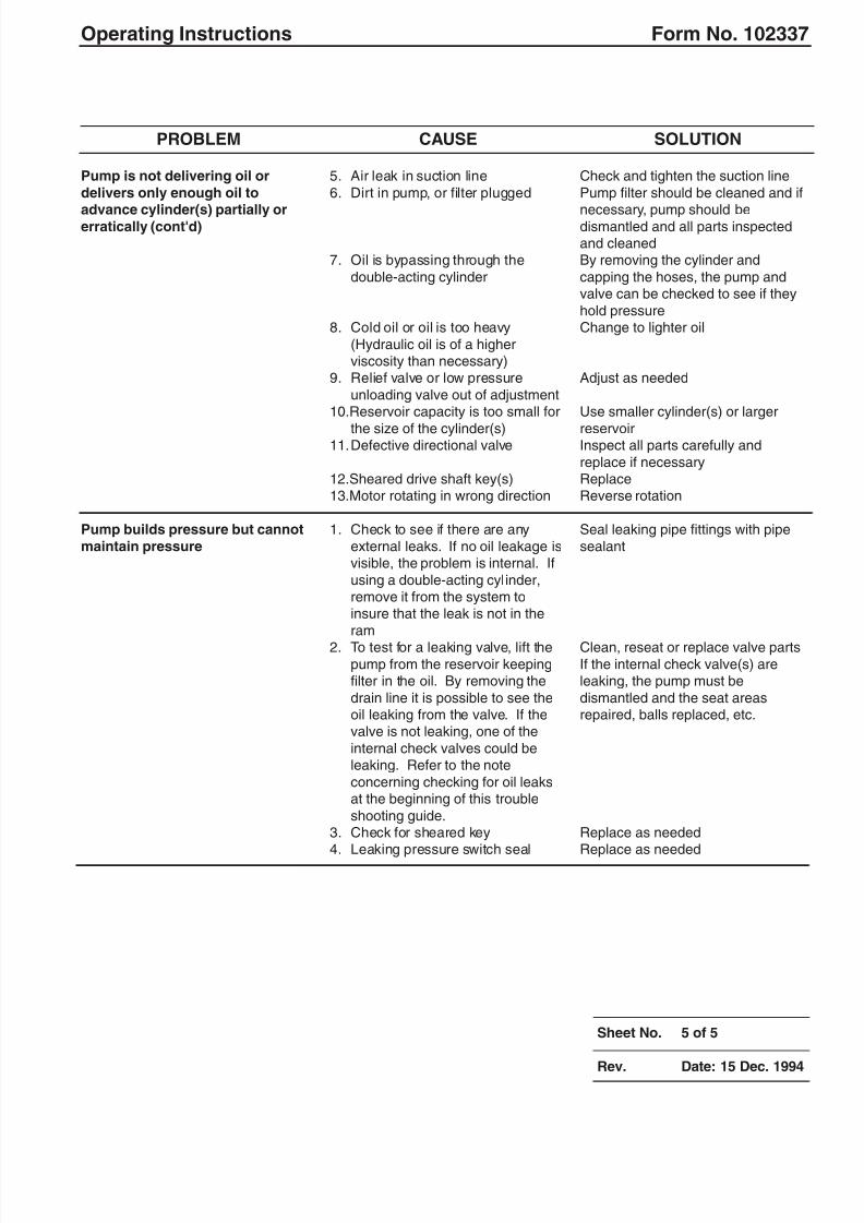
Pump is not delivering oil ordelivers only enough oil toadvance cylinder(s) partially or
erratically.
1. Oil level too low
2. Pump needs to be primed
3. Loose fitting coupler to cylinder
Fill reservoir to within 1" of filler plug
with all cylinders retractedPrime pump
Check quick-disconnect couplings tocylinders
Inspect couplers to insure that theyare completely coupled
Occasionally couplers have to bereplaced because the ball checkdoes not stay open due to wear
Bleed the system
Motor Does Not Run
WARNING: Disconnect
power supply before removing
cover. Any electrical work shouldbe performed by a qualifiedelectrician.
1. Pump not turned to "On" position
2. Unit is not plugged in3. No voltage supply
4. Broken lead wire or defectivepower cord plug
5. Defective switches6. Defective motor7. Thermal protector switch inside
motor housing is open.8. Defective starter relay
Flip toggle switch to run position,push start button
Plug in unitCheck line voltage
Replace defective parts
Check switchesReplace motorWait for motor to cool before
restartingReplace defective parts
PROBLEM CAUSE SOLUTION
8/14/2019 Power Team PQ120 Manual
http://slidepdf.com/reader/full/power-team-pq120-manual 9/10
Operating Instructions Form No. 102337
Sheet No. 5 of 5
Rev. Date: 15 Dec. 1994
Pump builds pressure but cannot
maintain pressure
1. Check to see if there are any
external leaks. If no oil leakage isvisible, the problem is internal. If
using a double-acting cylinder,remove it from the system toinsure that the leak is not in the
ram
2. To test for a leaking valve, lift thepump from the reservoir keepingfilter in the oil. By removing the
drain line it is possible to see theoil leaking from the valve. If thevalve is not leaking, one of the
internal check valves could beleaking. Refer to the note
concerning checking for oil leaksat the beginning of this trouble
shooting guide.3. Check for sheared key4. Leaking pressure switch seal
Seal leaking pipe fittings with pipe
sealant
Clean, reseat or replace valve partsIf the internal check valve(s) areleaking, the pump must be
dismantled and the seat areasrepaired, balls replaced, etc.
Replace as neededReplace as needed
Pump is not delivering oil or
delivers only enough oil to
advance cylinder(s) partially orerratically (cont'd)
5. Air leak in suction line
6. Dirt in pump, or filter plugged
7. Oil is bypassing through the
double-acting cylinder
8. Cold oil or oil is too heavy
(Hydraulic oil is of a higherviscosity than necessary)
9. Relief valve or low pressure
unloading valve out of adjustment10.Reservoir capacity is too small for
the size of the cylinder(s)11.Defective directional valve
12.Sheared drive shaft key(s)13.Motor rotating in wrong direction
Check and tighten the suction line
Pump filter should be cleaned and if
necessary, pump should bedismantled and all parts inspectedand cleanedBy removing the cylinder and
capping the hoses, the pump andvalve can be checked to see if they
hold pressureChange to lighter oil
Adjust as needed
Use smaller cylinder(s) or larger
reservoirInspect all parts carefully and
replace if necessaryReplaceReverse rotation
PROBLEM CAUSE SOLUTION

8/14/2019 Power Team PQ120 Manual
http://slidepdf.com/reader/full/power-team-pq120-manual 10/10
Operating Instructions, Form No. 102337, Back sheet 5 of 5
Pump will not build full pressure 1. Faulty pressure gauge
2. Check for external leakage
3. Check the relief valve setting;check the external pressureregulator
4. Look for internal leakage indouble-acting cylinders
5. Check for leaks in the valve6. Valve seat may be damaged.
Check for oil coming out thereturn line (2-way valve)
7. Valve shear seals or o-rings maybe damaged. Check for oil
coming out the return line (3-way,4-way)
8. Valve rotor lapped surface may
be damaged (3-way, 4-waymanual valves)
9. Inspect the pump for internalleakage
10.Sheared key(s)11.High pressure pump inlet or outlet
ball checks in the pump areleaking
Calibrate gauge
Seal any faulty pipe fitting with pipesealant
Lift the pump from the reservoirkeeping the filter immersed in oil.Note the pressure reading when the
relief valve begins to open up. Iffunctioning normally, it should start
to leak off at relief valve pressure.
Remove the cylinder from the pump.If the pump builds full pressure, thecylinder is defective.
Clean and reseat partsReplace the valve seat stem or
reseat pump body seat
Replace shear seals and/or o-ringsin valve section
Lap surface or replace rotor
Same procedure as above but lookfor leaks around the entire innermechanism. If there are no visible
leaks, the low-to-high pressure ballcheck may be leaking. Remove all
parts. Check the end plate body forany damage to the seat area. Clean
and reseat if necessary. Inspect the
ball for damage and replace ifnecessary, then reassemble
ReplaceReseat or replace valve head
Electric motor cuts out 1. Insufficient power supply2. Faulty motor and/or thermal
protector
ReplaceReplace
Cylinders will not retract 1. Check the system pressure; if thepressure is zero, the control valve
is releasing pressure and theproblem may be in the cylinder(s),mechanical linkage connected to
cylinder(s), mechanical linkageconnected to cylinder(s), or quick-
disconnect couplings2. Defective valve
Check the cylinders for broken returnsprings and check couplers to insure
that they are completely coupled.Occasionally couplers have to bereplaced because one check does
not stay open in the coupled position
Test valve operation and inspect
parts. Replace if necessary
Pump delivers excess oil pressure 1 Relief valve not properly set2. Check pressure gauge
Adjust the relief valveCalibrate gauge
PROBLEM CAUSE SOLUTION