post, bueno english.pdf
TRANSCRIPT
Ge
Post
Processing
TM
FeatureCAM General Post Processor
2
Information in this document is subject to change without notice. No part of this document may be reproduced or transmitted in any form or by any means, electronic, or mechanical, for any purpose, without the express written permission of Engineering Geometry Systems. The software described in this document is furnished under a license agreement. The software may be used or copied only in accordance with the terms of the agreement.
© 1995 – 2001 Engineering Geometry Systems. All rights reserved.
FeatureCAM, EZFeatureMILL FeatureTURN, EZFeatureTURN, FeatureMILL3D and FeatureCAM and are trademarks of Engineering Geometry Systems in the United States of America and other countries.
Restricted Rights Legend
The Program and Program Materials are provided with RESTRICTED RIGHTS. Use, duplication, or disclosure by the United States Government is subject to restrictions as set forth in subparagraph (c)(1)(ii) of the Rights in Technical Data and Computer Software Clause at DFARS 252.227-7013, Manufacturer is the Licensor: Engineering Geometry Systems.
Permission to Copy for Licensed Users
EGS grants permission for licensed users to print copies of this manual or portions of this manual for personal use only. Schools that are licensed to use FeatureCAM may make copies of this manual or portions of this manual for students currently registered for classes where FeatureCAM is used.
June 2003 Tenth Edition
Engineering Geometry Systems 275 East South Temple, Suite 305 Salt Lake City, UT 84111
FeatureCAM General Post Processor
3
Overview of post processing in FeatureCAM XBUILD is the general post processing program for milling turning and turn/milling. It is separate from FeatureCAM. To run the general post processors ,click on XBUILD in the FeatureCAM group under the Start menu or click the Edit button in the Post Options dialog box.
Please note that throughout this section the Post module is referred to as though it were separate from the FeatureCAM program. It is in fact, part of the FeatureCAM program, but for the sake of simplicity it is referred to as a separate entity from FeatureCAM. This concept is important to understanding many of the references to the Post module.
Various machine tool manufacturers have implemented CNC (Computerized Numerical Control) program standards that differ in detail from each other (and from the EIA RS-274C standard). Because of this wide range of standards, XBUILD was designed to allow for the creation of CNC information files for virtually any CNC. The process of creating a CNC information file is also referred to as building a postprocessor.
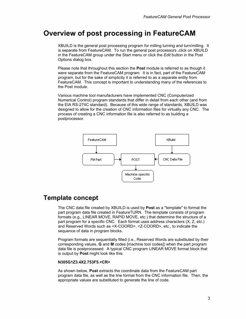
Template concept The CNC data file created by XBUILD is used by Post as a "template" to format the part program data file created in FeatureTURN. The template consists of program formats (e.g., LINEAR MOVE, RAPID MOVE, etc.) that determine the structure of a part program for a specific CNC. Each format uses address characters (X, Z, etc.) and Reserved Words such as <X-COORD>, <Z-COORD>, etc., to indicate the sequence of data in program blocks.
Program formats are sequentially filled (i.e., Reserved Words are substituted by their corresponding values, G and M codes [machine tool codes]) when the part program data file is postprocessed. A typical CNC program LINEAR MOVE format block that is output by Post might look like this:
N305G1Z3.4X2.753F5.<CR>
As shown below, Post extracts the coordinate data from the FeatureCAM part program data file, as well as the line format from the CNC information file. Then, the appropriate values are substituted to generate the line of code.
FeatureCAM General Post Processor
4
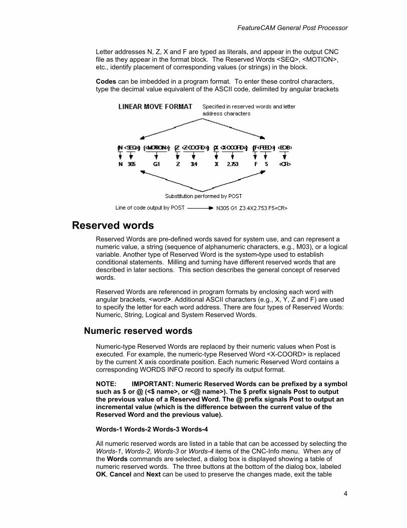
Letter addresses N, Z, X and F are typed as literals, and appear in the output CNC file as they appear in the format block. The Reserved Words <SEQ>, <MOTION>, etc., identify placement of corresponding values (or strings) in the block.
Codes can be imbedded in a program format. To enter these control characters, type the decimal value equivalent of the ASCII code, delimited by angular brackets
Reserved words Reserved Words are pre-defined words saved for system use, and can represent a numeric value, a string (sequence of alphanumeric characters, e.g., M03), or a logical variable. Another type of Reserved Word is the system-type used to establish conditional statements. Milling and turning have different reserved words that are described in later sections. This section describes the general concept of reserved words.
Reserved Words are referenced in program formats by enclosing each word with angular brackets, <word>. Additional ASCII characters (e.g., X, Y, Z and F) are used to specify the letter for each word address. There are four types of Reserved Words: Numeric, String, Logical and System Reserved Words.
Numeric reserved words Numeric-type Reserved Words are replaced by their numeric values when Post is executed. For example, the numeric-type Reserved Word <X-COORD> is replaced by the current X axis coordinate position. Each numeric Reserved Word contains a corresponding WORDS INFO record to specify its output format.
NOTE: IMPORTANT: Numeric Reserved Words can be prefixed by a symbol such as $ or @ (<$ name>, or <@ name>). The $ prefix signals Post to output the previous value of a Reserved Word. The @ prefix signals Post to output an incremental value (which is the difference between the current value of the Reserved Word and the previous value).
Words-1 Words-2 Words-3 Words-4
All numeric reserved words are listed in a table that can be accessed by selecting the Words-1, Words-2, Words-3 or Words-4 items of the CNC-Info menu. When any of the Words commands are selected, a dialog box is displayed showing a table of numeric reserved words. The three buttons at the bottom of the dialog box, labeled OK, Cancel and Next can be used to preserve the changes made, exit the table
FeatureCAM General Post Processor
5
without saving any changes, and advance to the next Words dialog box respectively.
Each row of the table contains information about the format of each reserved word. The columns of the table are described below.
LD_ZR
LD_ZR outputs leading zeros if this option is toggled ON. Zeros are output in all leading positions of the value, excluding significant digit locations (e.g., 1 “with a 3.4 format would output two leading zeros [001]).
TRL_ZR
TRL_ZR outputs Trailing Zeros when this option is set to ON. Zeros are output in all trailing positions of each value output for the designated Reserved Word, excluding significant digit locations (e.g., 10" with a 3.4 format would be output with four trailing zeros [100000]).
DEC_PT
DEC_PT turns on the decimal point character ON/OFF (e.g., when DEC_PT is toggled ON, 100 inches is output as 100.0). The character (either a [,] representing the European decimal, or a [.] representing the U.S. decimal) is specified in General in the CNC Info menu.
UNS_V
UNS_V (Unsigned Value) is toggled ON, positive values are always generated. For example, some controls may require <ARC-X> and <ARC-Y> (I and J modifiers for circular interpolation to be unsigned).
+SIGN
+SIGN outputs the plus sign (+) for positive integers when toggled ON.
FORMT
FORMT specifies the number of digits in the numeric value, represented by each numeric-type Reserved Word. Numbers are specified in the format, N.n, where N represents the maximum number of digits to the left of the decimal point, and n is the maximum number of digits to the right of the decimal point. For example, entering 3.4 specifies a maximum + or – departure of 999.9999, or a minimum departure of 0.0001 can be used. In the Words table, a numeric format can be specified for each Reserved Word that requires it.
FACTR
FACTR modifies numeric values during postprocessing. Each value that is output by Post is multiplied by the specified number in FACTR. For example, some controls require arcs to be calculated from center to start point. This requires the use of a –1 factor for <ARC-X> and <ARC-Y>.To generate the unsigned distance from the arc's start position to the center of an arc, change the status of UNS_V to ON in WORDS INFO for these Reserved Words.
String reserved words String-type Reserved Words provide a set of characters previously defined in
FeatureCAM General Post Processor
6
XBUILD. For example, G01, G02, or M03 could be strings that were previously defined as <MOTION> and <SPINDLE>.
Establishing conditional statements System and logical-type Reserved Words are used together in program formats to set up conditional statements that are evaluated by Post. If a conditional statement is true, or false, Post either includes, or omits, certain data from the program format. The format for conditional statements is:
<IF><Logical Reserved Word><THEN> {N<SEQ>}... <ENDIF>
or
<IFNOT><Logical Reserved Word><THEN> {N<SEQ>}... <ENDIF>
In the first conditional statement (below), the data between the words <THEN> and <ENDIF> are only output if cutter diameter compensation is ON. In the second conditional statement, the data between the words <THEN> and <ENDIF> are only output if cutter diameter compensation is not turned ON.
<IF><COMP-ON><THEN>
{N<SEQ>}{<COMP-STAT>}{<MOTION>}{X<X-COORD>}{Y<Y-COORD>}{Z<Z-COORD>}{F<FEED>}<EOB>
<ENDIF>
<IFNOT><COMP-ON><THEN>
{N<SEQ>}{<MOTION>}}{X<X-COORD>}{Y<Y-COORD>}{F<FEED>}<EOB>
<ENDIF>
File menu Load CNC
Load CNC displays a dialog box in which the disk drive, directory path, and file name are selected using the mouse. Below the list of file names, is a check box labeled, Use Extension Filter. If this box is checked, only files with the extension .CNC are shown in the file list. If this box is not checked all files regardless of extension are shown in the file list.
Click Cancel to exit the dialog box without loading a file. Pressing the Esc key acts the same as clicking Cancel with the mouse.
Save CNC Save CNC saves new or updated CNC information in a CNC Data file (or postprocessor). When Save CNC is selected, a data file is generated which can later be loaded into FeatureTURN through Post Options.
FeatureCAM General Post Processor
7
Document CNC Document CNC creates a text file from the current CNC data file. This text file can be edited and printed with any text editor.
When this command is selected, the same dialog box as the Save CNC command is displayed. The file saved with this command is given the file extension .CNX.
Quit Quit exits XBuild. If you quit and changes have been made to the currently loaded data file, a dialog box appears prompting you to confirm the quit. You are not prompted to save the file.
Formats menu The Formats menu in XBUILD enters specific program formats for the various of a part program. Each format is made up of combinations of Reserved Words, literals, comments, and user-defined variables.
Formats editor When a program format is selected from the Formats menu, the XBuild program shifts into the Formats editor and displays the selected format on the screen. The formats editor has two menus which are used in editing the selected format; however, these menus do not change from one format to another. All program formats are edited in the same manner.
File menu
The Formats Editor File menu has only two commands, Word List and Quit.
• Words list displays a list of the reserved words in the lower right corner of the screen. This list can be scrolled up and down with the scroll bar on the right. The reserved words are grouped into four categories as described earlier, Numeric, String, Logical, and System.
1. To place a reserved word into the format, (displayed in the main part of the screen) scroll the Words List to the desired word and select it. The word is placed in the program format at the test insertion bar. The test insertion bar is a blinking vertical bar.
2. If it is not visible, move the mouse to the format window and click the mouse.
3. Remove reserved words from the program format with the backspace key. The text editing functions in the Formats Editor are similar to those of any Windows word processor.
4. Insert modal delimiters by clicking the mouse in the check box at the bottom of the Words List.
5. The Words List can be closed like any window, or by selecting Word List a second time in the File menu.
• Quit exits the Formats Editor saves the modified format in memory. If any changes have been made to the selected format when the Quit command is
FeatureCAM General Post Processor
8
selected, you are prompted to save (Yes or No) the changes that were made, or to cancel the Quit command. If Cancel is selected, the Formats Editor remains active.
Edit menu
This menus contains five commands found in most Windows programs. These are briefly described here, but for more details, see the Windows User’s Manual (Using the Clipboard).
1. Undo can be used to “undo” the last action. If a reserved word was placed incorrectly, the Undo command removes it.
2. Cut removes the selected text and places it in the clipboard where it can be recalled with the Paste command.
3. Copy places the selected text to the clipboard in the same way as the Cut command does, except that the selected text is not removed, from its selected location.
4. Paste places the contents of the clipboard at the text insertion point.
5. Delete removes the selected text without copying it to the clipboard.
Using expressions in formats Expressions are surrounded by square brackets “[“ “]”. They are evaluated prior to being output. This example multiplies the current X coordinate by five: [<X-COORD>*5]. This example offsets a rapid move by (5,5): N<SEQ>G00 X[<X-COORD>+5] Y[<Y-COORD>+5] Z<Z-COORD>.
Printing square brackets
Since “[“ and “]” are now special characters, for them to be output in the NC code, you would have to enter them as <91> and <93>, respectively. When opening an existing CNC file that contains the characters, they will be automatically converted to <91> and <93>.
Numeric operators
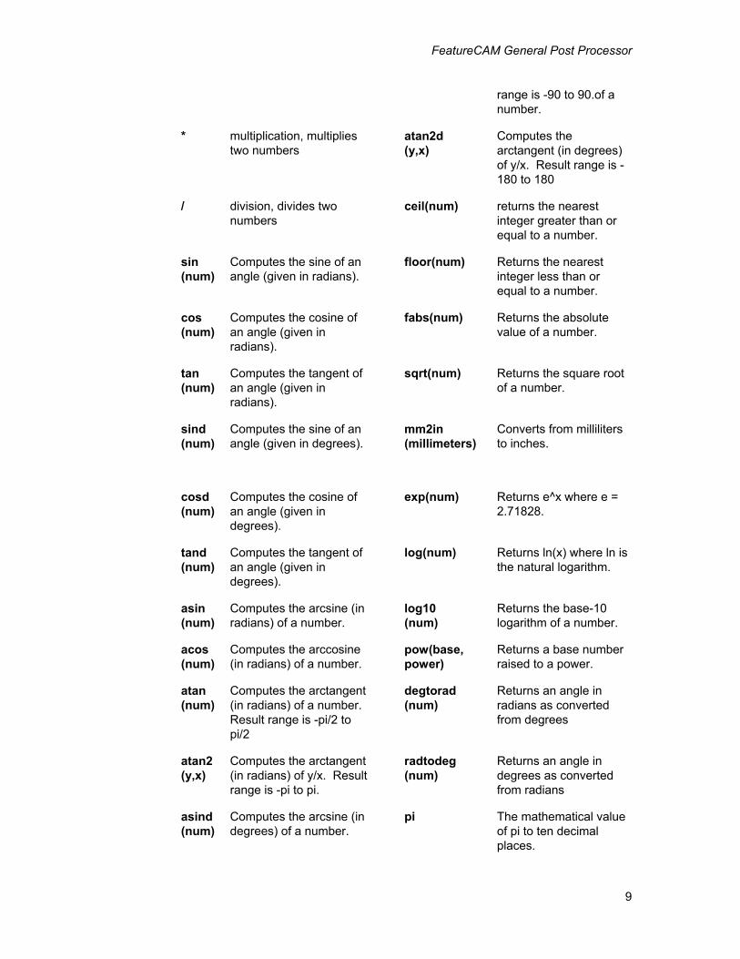
XBUILD accepts the following numeric operators:
+ • addition, adds two numbers.
• string concatenation, joins two strings.
• if given a string and a number, the string is converted into a number and then the two numbers are added.
acosd (num)
Computes the arccosine (in degrees) of a number.
- subtraction, subtracts two numbers
atand (num)
Computes the arctangent (in degrees) of a number. Result
FeatureCAM General Post Processor
9
range is -90 to 90.of a number.
* multiplication, multiplies two numbers
atan2d (y,x)
Computes the arctangent (in degrees) of y/x. Result range is -180 to 180
/ division, divides two numbers
ceil(num) returns the nearest integer greater than or equal to a number.
sin (num)
Computes the sine of an angle (given in radians).
floor(num) Returns the nearest integer less than or equal to a number.
cos (num)
Computes the cosine of an angle (given in radians).
fabs(num) Returns the absolute value of a number.
tan (num)
Computes the tangent of an angle (given in radians).
sqrt(num) Returns the square root of a number.
sind (num)
Computes the sine of an angle (given in degrees).
mm2in (millimeters)
Converts from milliliters to inches.
cosd (num)
Computes the cosine of an angle (given in degrees).
exp(num) Returns e^x where e = 2.71828.
tand (num)
Computes the tangent of an angle (given in degrees).
log(num) Returns ln(x) where ln is the natural logarithm.
asin (num)
Computes the arcsine (in radians) of a number.
log10 (num)
Returns the base-10 logarithm of a number.
acos (num)
Computes the arccosine (in radians) of a number.
pow(base, power)
Returns a base number raised to a power.
atan (num)
Computes the arctangent (in radians) of a number. Result range is -pi/2 to pi/2
degtorad (num)
Returns an angle in radians as converted from degrees
atan2 (y,x)
Computes the arctangent (in radians) of y/x. Result range is -pi to pi.
radtodeg (num)
Returns an angle in degrees as converted from radians
asind (num)
Computes the arcsine (in degrees) of a number.
pi The mathematical value of pi to ten decimal places.
FeatureCAM General Post Processor
10
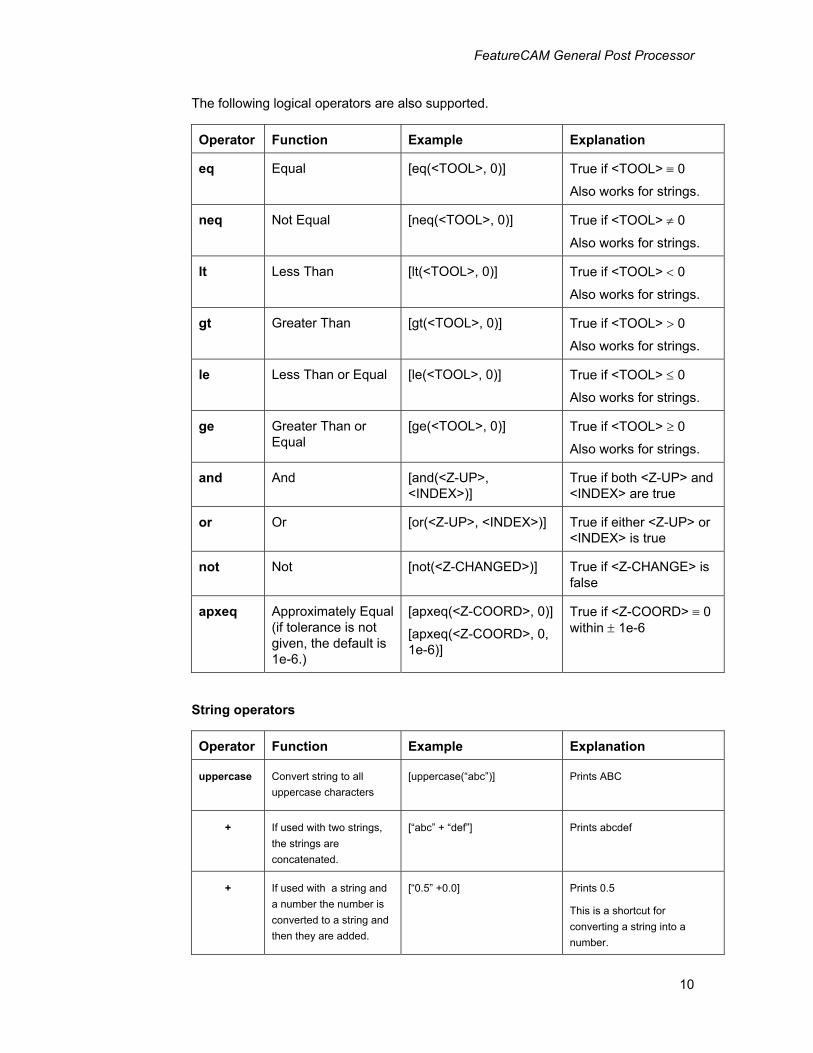
The following logical operators are also supported.
Operator Function Example Explanation
eq Equal [eq(<TOOL>, 0)] True if <TOOL> ≡ 0
Also works for strings.
neq Not Equal [neq(<TOOL>, 0)] True if <TOOL> ≠ 0
Also works for strings.
lt Less Than [lt(<TOOL>, 0)] True if <TOOL> < 0
Also works for strings.
gt Greater Than [gt(<TOOL>, 0)] True if <TOOL> > 0
Also works for strings.
le Less Than or Equal [le(<TOOL>, 0)] True if <TOOL> ≤ 0
Also works for strings.
ge Greater Than or Equal
[ge(<TOOL>, 0)] True if <TOOL> ≥ 0
Also works for strings.
and And [and(<Z-UP>, <INDEX>)]
True if both <Z-UP> and <INDEX> are true
or Or [or(<Z-UP>, <INDEX>)] True if either <Z-UP> or <INDEX> is true
not Not [not(<Z-CHANGED>)] True if <Z-CHANGE> is false
apxeq Approximately Equal (if tolerance is not given, the default is 1e-6.)
[apxeq(<Z-COORD>, 0)]
[apxeq(<Z-COORD>, 0, 1e-6)]
True if <Z-COORD> ≡ 0 within ± 1e-6
String operators
Operator Function Example Explanation
uppercase Convert string to all uppercase characters
[uppercase(“abc”)] Prints ABC
+ If used with two strings, the strings are concatenated.
[“abc” + “def”] Prints abcdef
+ If used with a string and a number the number is converted to a string and then they are added.
[“0.5” +0.0] Prints 0.5
This is a shortcut for converting a string into a number.
FeatureCAM General Post Processor
11
Some example expressions using operators are:
1. Output Z as 0 if Z is within 0.0001 of zero.
<IF>[apxeq(<Z-COORD>, 0 , 0.0001)]<THEN> N<SEQ> G00 X<X-COORD> Y<Y-COORD> Z0<EOB>
<ENDIF>
2. Rapid move using polar coordinates.
N<SEQ> I0 J0<EOB> N<SEQ> G10 R[sqrt(pow(<X-COORD>, 2) + pow(<Y-COORD>, 2))] H[D|3.2|1.0:atan2d(<Y-COORD>, <X-COORD>)]<EOB>
3. Output Z as 15 if Z is between 10 and 20 inclusively
<IF>[and(ge(<Z-COORD>, 10), le(<Z-COORD>, 20))]<THEN> N<SEQ> G00 X<X-COORD> Y<Y-COORD> Z15<EOB> <ENDIF> 4. If the P variable, P1, is not set, then set it to the string, “G0”
<IF>[eq(<P1>,"")]<THEN> [<P1>=”G0”] <ENDIF>
Assignment and variables
The result of any operation can be assigned to another keyword or to a variable. Variable names can consist of one more characters and are not case sensitive. The first character must be alphabetic and the rest can be any combination of alphanumeric characters and the underscore character. Examples of variables are: ABC, X23, and CENTER_PT.
Note that the result of an assignment operation is the value of the keyword or variable being assigned. For example the result is 5 for [x = 5].
Examples of assignment and variable usage are:
1. Increase the current value of the keyword <Z-COORD> by ten.
[<Z-COORD> = <Z-COORD> + 10]
2. Set the variable, XVAR, to the current value of <X-COORD>, then double XVAR. Note that these statements do not change the value of <X-COORD>
[x_var = <X-COORD>]
[x_var = x_var * 2]
3. Set the variable, FEATURE, to the string, “hole”, then add the string, “top “ to the variable, FEATURE, and set the new string to the variable, NAME.
[feature=”hole”]
[name= “top ” + feature]
FeatureCAM General Post Processor
12
Comments
You can place a comment in a .CNC file by inserting a “#” as the first character in the expression. An example comment might be:
[# This is a comment]
A comment is text that XBUILD ignores but that is useful to you for annotation purposes. Although, comments are neither printed nor evaluated, they are helpful if another person is trying to understand your CNC file.
Formatting expressions
The format for an expression can be customized by preceding the expression with an optional format specification. The format specification is separated from the expression by a “:”.
LTDUP|Format|Factor Where: L stands for leading zeros
T stands for trailing zeros
D stands for decimal point
U stands for unsigned value
P stands for plus sign
Format specifies the number of digits (e.g. 3.4)
Factor specifies the multiplier (e.g. 1.0)
The above form is in correspondence with the Words Info dialog in XBUILD.
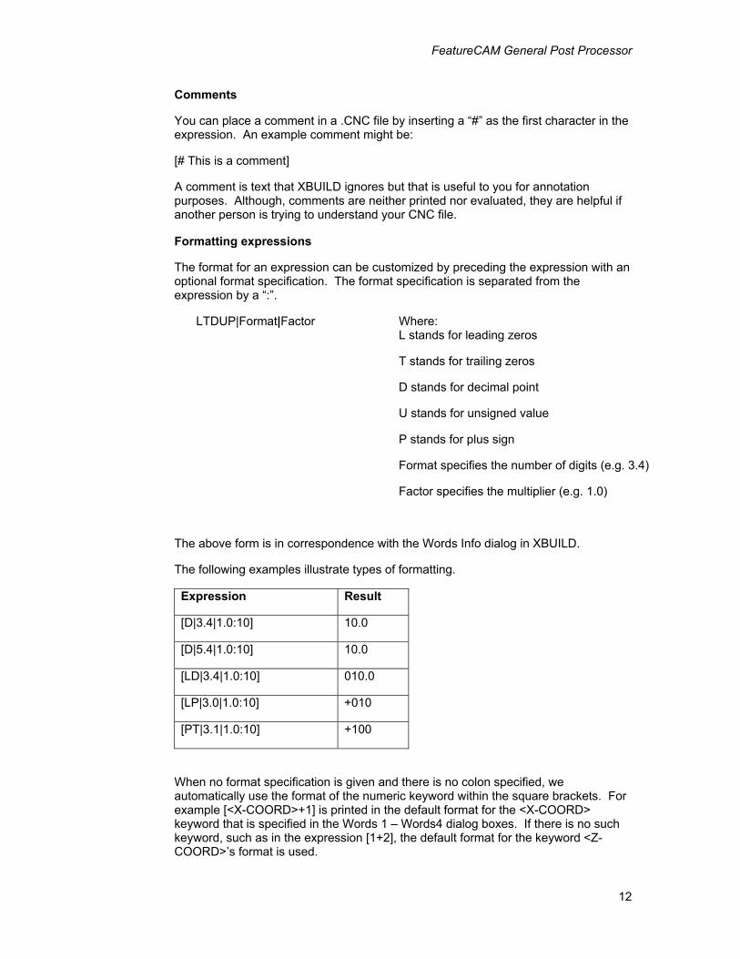
The following examples illustrate types of formatting.
Expression Result
[D|3.4|1.0:10] 10.0
[D|5.4|1.0:10] 10.0
[LD|3.4|1.0:10] 010.0
[LP|3.0|1.0:10] +010
[PT|3.1|1.0:10] +100
When no format specification is given and there is no colon specified, we automatically use the format of the numeric keyword within the square brackets. For example [<X-COORD>+1] is printed in the default format for the <X-COORD> keyword that is specified in the Words 1 – Words4 dialog boxes. If there is no such keyword, such as in the expression [1+2], the default format for the keyword <Z-COORD>’s format is used.
FeatureCAM General Post Processor
13
Suppressing the printing of an expression
To suppress the printing of the assignment result, specify only the colon as the format specification. Neither of the following expressions will print a value because the first character of the expression:
[:x_var=<X-COORD>+1] [:<Y-COORD>*2]
Example expressions
[# Set x = 3, y = 5, z = 0.0001]
X[<X-COORD>=3]Y[<Y-COORD>=5]Z[<Z-COORD>=0.0001]<EOB>
[# Calc (x + 3)*2]
[(<X-COORD>+3)*2]<EOB>
[# Calc sqrt(pow(x, 2) + pow(y, 2))]
[sqrt(pow(<X-COORD>,2)+pow(<Y-COORD>,2))]<EOB>
[# Calc atan2d(y, x)]
[atan2d(<Y-COORD>,<X-COORD>)]<EOB>
[# Is z = 0 within +-0.001? If so, print “Yes”]
<IF>[apxeq(<Z-COORD>,0,0.001)]<THEN>
Yes<EOB>
<ENDIF>
[# Print special charcters]
<91><93><EOB>
[# Format x using tool's format]
[<TOOL>:<X-COORD>]<EOB>
[# Format -x as LTDUP|2.2|2]
FeatureCAM General Post Processor
14
[LTDUP|2.2|2:-<X-COORD>]<EOB>
[# Set x = 1 without printing anything]
[:<X-COORD>=1]<EOB>
[# Is x != 0 and y != 0?]
<IF>[and(not(apxeq(<X-COORD>,0)),not(apxeq(<Y-COORD>,0)))]<THEN>
Yes<EOB>
<ENDIF>
[# Set variable a = x]
[a=<X-COORD>]<EOB>
[# Calc a + 5]
[a+5]<EOB>
Entering mixed printable ASCII and non-printable codes
Different systems may allow for ASCII (American Standard Code for Information Interchange) control character(s) (non-printable characters). Control characters such as:
• <13> for a carriage return
• <10> for a line feed
• <32> for a space
• <9> for a horizontal tab
• <91> for a left square bracket
• <93> for a right square bracket
can be imbedded in a program format. To enter control characters, type the decimal value equivalent of the ASCII code, delimited by angular brackets <>.
Milling general post processor The Xbuild program is a separate program from FeatureCAM. To run Xbuild, click on Xbuild in the FeatureCAM group under the Start menu.
FeatureCAM General Post Processor
15
Various machine tool manufacturers have implemented CNC program standards that differ from each other and from the EIA RS-274C standard. Because of this wide range of standards, XBuild creates CNC data files that FeatureCAM can run on virtually any CNC.
CNC info menu Use the CNC info menu in XBuild to enter general information and formats for the reserved words used in the FeatureCAM program. Each command in the CNC info menu displays a different dialog box for entering formatting information.
General options General opens a list of options pertaining to the output program format. The comment block describes the post processor.
Any parameter may be changed by selecting it, typing the value, or toggling to the desired selection.
These values are default values when no CNC Data file has been loaded into the XBUILD program. When a file is loaded several or all of these values may change.
Machine Type
The Machine type classifies the type of post. The choices are
• Milling – use this type of post for 2.5D or 3D milling.
• Turning – use this classification for 2-axis turned parts
• Turn/MILL – use this type of post for lathe with powered rotary tools.
This distinction controls type of reserved words and program formats that are available in the post.
Dimension
Dimension toggles between Inch and Metric output. Post uses the selection to convert the dimensions that affect X and Y coordinates as well as feed rate. The setting in the CNC Data file takes precedence over the assumed inch unit in FeatureCAM. If a part program is written in inch units, and is processed with a metric CNC data file, the resulting part program is converted (using standard conversion constants) into metric units.
EOB
EOB defines the end of block character(s) (<EOB>). It is recommended that the default characters be used (i.e., <13><10>, carriage return and line feed).
Decimal Point
Decimal Point defines the decimal point character. This character is usually a period (.) for United States controls, and a comma (,) for European controls.
2-Axis Machine
2-axis machine removes ramping moves and ensures that the plunge move is
FeatureCAM General Post Processor
16
performed in a single move. Overall, this setting eliminates unnecessary Z moves that cannot be handled by a 2-axis machine.
NC File Ext.
This is the default file extension for you CNC programs. For example if it is set to “.txt”, and your part is called “bracket”, then the gcode file will be called “bracket.cnc”.
Circ. Interpol.
Circ. Interpol. toggles between Multi-Quadrant and Single Quadrant and specifies the programming format on the CNC for which the postprocessor is being built. For example, if the Numerical Control cannot drive an arc across a quadrant line (plus or minus X and Y axes), then select Single Quadrant circular interpolation.
Feed Max
Feed Max. is the maximum feed rate limit for the CNC machine.
Feed Min
Feed Min. is the minimum feed rate limit for the CNC machine.
Max. Macros
Max. Macros specifies the maximum number of macros (sub-programs) available on the control. If macros are not available, set this value to zero, and select Not Available in the Macro Type parameter, described next.
Macro Type
Macro Type specifies how macros are formatted when the part program requires them.:
• Local places macro definitions within the main NC part program.
• End of Prog. places macro definitions at the end of the main part program (e.g., Heidenhain controls). The PROGRAM END program format should be specified for output at the end of the main program and the FILE END program format should be specified for output at the end of these macro definitions.
• Not Available signals Post that macros are not available.
• Indiv. Files places macro definitions in a separate file (e.g., FANUC and GE MC 2000 controls). The name of each macro file consists of the assigned name that was specified in Post and the system-assigned macro number The internal sub-program name is automatically added to the main program name as the external file name.
• One File places all macro definitions in one file. Post generates two files, the main part program and a file containing all macros. This option can output to Bridgeport controls via the EZ-Utils module, CNC COMMUNICATION option (Heidenhain DNC utility).
The name of the macro file consists of the assigned name specified in Post, MA (representing the macro specification) and the .TXT file extension. For example, SAMPLEMA.TXT (macro file) and SAMPLE.TXT.
FeatureCAM General Post Processor
17
Call local macro after it is defined
Some controls (such as the Heidenhain 370) automatically execute macros when they are defined. For these controls uncheck Call local macro after it is defined so that the macro is not called twice. For other types of controls, leave this option checked.
Seq max
This is the maximum value for sequence numbers. After reaching this number, the sequence numbers start over. If the Seq max radio button is not clicked, then no limit is set.
Include first canned cycle move in macro
Checking this option will output the current position as the first location of a macro. Without this checked, the first move will not be in the macro, instead it is assumed that it is output on the canned cycle line.
To properly include the first move in a macro, you will need to use a combination of this checkbox and the logical variable <CYCLE_MACRO> to suppress actually performing the canned cycle on the canned cycle line.
For a Fanuc 0M, if a canned cycle line ends with K0 then the machine goes into canned cycle mode, but the actual canned cycle is not performed. Here is the drilling format for the Fanuc 0M.
{N<SEQ>}<CYCLE>{X<X-COORD>}{Y<Y-COORD>}R<ABS-ZCLEAR>Z<ABS-DEPTH>F<FEED> <IF><CYCLE-MACRO><THEN> K0 <ENDIF> <EOB>
Note that Include first canned cycle move in macro checkbox must be checked so that the initial location is output in the macro.
NC codes Motions
Motions describes motion types required by the NC machine. All of these codes must be specified. For example, Linear is generally defined as G1, but may be changed to G01, or any other string (up to 11 characters). All motion commands are passed to Post via the string-type Reserved Word, <MOTION>. The Motions group has these options:
Rapid= rapid move Linear= feed move Circ. CW = circular interpolation, clockwise Circ. CCW = circular interpolation, counter-clockwise
Rotary Tools
This section of NC codes is only displayed for turn/mill posts. It deals with coolant specifications. Coolant selections use the string-type Reserved Word, <COOLANT>.
FeatureCAM General Post Processor
18
Cool OFF = coolant off Cool Mist = coolant on, mist Cool Flood = coolant on, flood
Miscellaneous
Miscellaneous contains selections for Spnd CW (Spindle Start Clockwise) and Spnd CCW (Spindle Start Counter-Clockwise). Both of these specify that the spindle is ON and the direction code. Both spindle selections use the string-type Reserved Word, <SPINDLE>. Other Miscellaneous codes include coolant specifications. Coolant selections use the string-type Reserved Word, <COOLANT>. The Miscellaneous group has these options:
Spnd. CW = spindle on, clockwise Spnd. CCW = spindle on, counterclockwise Cool OFF = coolant off Cool Mist = coolant on, mist Cool Flood = coolant on, flood
Compensation
Compensation generates cutter diameter compensation in the output when turned On in FeatureCAM, and if it is built into the CNC data file. Compensation selections use the string-type Reserved Word, <COMP-STAT> for one of the below options, or an empty string is assigned if Compensation was not turned On in FeatureCAM. the Compensation group has these options:
Cancel = compensation off Left = compensation on cutter, applied to left in direction of travel Right = compensation on cutter, applied to the right in the direction of travel
Cycles
The following program formats are canned cycle formats. They are used for header, canned motion and cycle cancel blocks. The header block (for all canned cycles) must contain formats to position down to the clearance plane to drill the first hole.
• DRILL CYCLE specifies the header block for a drilling cycle.
• SPOT FACE CYCLE specifies header block for a spot face cycle.
• DEEP HOLE CYCLE specifies a deep hole cycle header block.
• TAP CYCLE specifies the header block for a tapping cycle.
• BORE (F-F) CYCLE specifies a header block for a boring (feed-in, feed-out) cycle.
• CHIP BREAK CYCLE specifies the header block for a chip break cycle.
• BORE (F-D-F) CYCLE specifies a boring (feed-in, dwell, feed-out) cycle header block.
• BORE (F-S-R) CYCLE specifies a boring (feed-in, stop spindle, rapid) cycle.
• BORE (No drag) Cycle specifies a boring (feed-in, stop spindle, move to side, retract) cycle.
FeatureCAM General Post Processor
19
• CYCLE CANCEL specifies the cycle cancel block for any of the canned cycles.
• CANNED MOVE specifies the format of canned cycles, following their initial definition.
Pecking types
Pecking types are the types of pecking performed for drilling and tapping
Reserved word table
Reserved Word Definition
<ABS-DEPTH> Absolute Z axis depth from Z axis origin, <ZSURF> – <DEPTH>
<ABS-STEP1> Absolute first step, <ZSURF> – <STEP1>
<ABS-ZCLEAR> Absolute position of Z Clear -- Z Clear + Z Surf (not used in incremental programming)
<ABS-ZRAPID> Absolute position of Z Rapid -- Z Rapid + Z Surf (not used in incremental programming)
<ANG-DPM> Wrapped feed rate, degrees per minute
<ANG-FPM> Wrapped feedrate, inch (or mm) per minute.
<ANG-INVTIME> Wrapped feedrate inverse time.
<ARC-X> Used in the circular interpolation block to specify the signed X distance from the start point of the arc, to the center of the arc along the X axis
<ARC-Y> Used in the circular interpolation block to specify the signed Y distance from the start point of the arc, to the center of the arc along the Y axis
<CHIP-TAP> True if tap cycle is CHIP.
<COMP-END> True if the move represents the end section for compensation (last element, or move of path), otherwise <COMP-END> is false
<COMP-ON> True if cutter diameter compensation is ON, otherwise <COMP-ON> is false
<COMP-MID> True if the move represents the middle section for compensation (between the first and last moves of path), otherwise <COMP-MID> is false
<COMP-NUM> Compensation number passed from FeatureCAM
<COMP-START> True if the move represents the start section for compensation (first element, or move of path), otherwise <COMP-START> is false
<COMP-STAT> When cutter diameter compensation status is selected, <COMP-STAT> establishes a right/left tool relationship with the part, and outputs the cutter compensation code at the first feed move of the profile path
<COOLANT> Generates the proper coolant code
<CW-SPINDLE> True if the spindle rotates in the clockwise direction, otherwise <CW-SPINDLE> is false
<CYCLE> Cycle-type identifier for drilling-type cycles
<CYCLE-DONE> True for the last hole location in a canned cycle. False otherwise.
<CYCLE-MACRO> True if the current segment is in a canned cycle
<CYCLE-RTRCT> The G code for either Z Rapid Retract or R Plane Retract depending on which plane is the current retract plane.
FeatureCAM General Post Processor
20
<DATE> Reproduces the date that the part program was post processed
<DEEP-TAP> True of tap cycle is DEEP.
<DEPTH> Z Depth value passed from FeatureCAM for drilling-type cycles
<DRILL_CPTED> True if drill moves are computed using linear moves. False if canned cycles.
<DRILLING> True if a drilling-type cycle is used in a segment, otherwise <DRILLING> is false, and a milling segment is in process
<DWELL> Reproduces the dwell value passed from FeatureCAM
<ENDIF> Last element in a conditional statement (must be on a line by itself)
<EOB> Specifies the end of block code for each line of a program format
<EXP-LENGTH> Corresponds to the Exposed length tool parameter. <FEED> Feed rate value identifier passed from FeatureCAM
<FINI-ALLOW> Finish allowance of a milling operation.
<FLOAT-TAP> True if tap cycle is FLOATING.
<FM-NAME> Reproduces the name of the FeatureCAM file.
<FIXTURE> Fixture ID number passed from FeatureCAM
<HELIX-PITCH> Pitch of helical move. Controlled by Max Ramp Angle attribute.
<IF> First element in a conditional statement, always followed by a logical-type Reserved Word to verify that a condition is true
<IFNOT> First element in a conditional statement, always followed by a logical-type Reserved Word to verify that a condition is false
<INC-DEPTH> Incremental depth from Z Clear, <DEPTH> + <ZCLEAR>
<INC-STEP1> Incremental first step, <STEP1> + <ZCLEAR>
<INDEX> True if 4th or 5th axis indexing is set in FeatureCAM. For the Segment start formats <INDEX> is only true when the indexing move is actually being performed.
<INDEXING> True if the user has turned on indexing for X,Y,or Z axis.
<IS-WORLD> True if the current setup is named WORLD.
<MACRO#> Macro number identifier (system-generated). Macros are not user definable, however some Macros are generated automatically, especially with multiple fixture parts. This number starts at 00 and increments automatically up to the Max Macros number that is contained on the General Information dialog box.
<MCSID> The name of the current setup.
<MIN-STEP> Corresponds to Minimum Peck drilling attribute.
<MOTION> Produces the correct motion-type (i.e., RAPID, LINEAR, CIRCULAR CW/CCW) for the various program formats (<MOTION> is specified via the MOTION COMMANDS option, CNC INFO top menu in BUILD)
<NO-DRAG-X> Amount to move over in X for no drag boring.
<NO-DRAG-Y> Amount to move over in y for no drag boring.
<NEXT-TL> Represents the next tool to be used (may be required by some controls)
FeatureCAM General Post Processor
21
<NOSE-RAD> Tool nose radius of an endmill or the tip radius of a threading tool or turning tool.
<OP-PASS> Milling comment that denotes “Rough” or “Finish” based on the type of pass.
<OP-TYPE> Milling comment that denotes the type of operation. This value is assigned by FeatureCAM based on the type of operation.
<OV-LENGTH> The overall length of the tool. Corresponds to the Overall Length parameter of a tool.
<PITCH> The pitch value for the Tap cycle. This value is in Z-distance per spindle revolution.
<PLANE> Produces the correct circular for the various program formats (<PLANE> is specified via the CIRCLUAR PLANES option, CNC INFO menu)
<PROG-NAME> Reproduces the output file name that is set in the Setup dialog box.
<RADIUS> Reproduces arc radius in a circular block
<RIGID-TAP> True of tap cycle is RIGID.
<ROT1-ANSI> Rotation about primary axis in ANSI style.
<ROT1-MATH> Rotation about primary axis in Mathematical style.
<ROT1-WIND> Rotation about primary axis in Winding style.
<ROT2-ANSI> Rotation about secondary axis in ANSI style.
<ROT2-MATH> Rotation about secondary axis in Mathematical style.
<ROT2-WIND> Rotation about secondary axis in Winding style.
<S-RAD> Generates the signed arc radius value in a circular block, +R<180 degrees and –R>180 degrees
<SEGM-ID> Provides the option to output the Seg ID (Segment Identifier) passed from FeatureCAM
<SEG-CMT> Comment on an operation. This is set under post variables. For controls that require comments to be a single line, SET-CMT must be only one line.
<SPEED> Spindle speed value passed from FeatureCAM
<SPINDLE> Used to turn the spindle ON to specify spindle rotation direction
<STATR-ANG> Initial angle of helical move. Added for Heidenhain.
<STEP1> First Peck value passed from FeatureCAM
<STEP2> Second Peck value passed from FeatureCAM
<THEN> Second element in a conditional statement, placed after a logical-type Reserved Word
<TLO> Tool length offset. Corresponds to Offset on tool properties.
<TOOL> Tool number passed from FeatureCAM
<TOOL-CMT> Tool comments.
<TOOL-DIAM> Tool diameter, passed from FeatureCAM.
<TOOL-ID> Tool ID from tool mapping dialog box.
<TOOL-LENGTH> Cutter length of endmills or length of drills.
<TOOL-NAME> A comment that indicates the name of the current tool.
FeatureCAM General Post Processor
22
<TOTAL-ANG> Total angle of a helical move. Added for Heidenhain.
<TPI-PITCH> The TPI value for the Tap cycle in an inch CNC file or the pitch value for the Tap cycle in a millimeter CNC file.
<USE-FIXTURE> True if using 5th axis positioning with Fixture Ids.
<WAS-WORLD> True if the previous setup is named WORLD
<WRAP> True if 4th axis wrapping is set.
<WRAP-Z-DOWN> True if wrapping and the tool is moving down in the Z direction.
<WRAP-Z-UP> True if wrapping and the tool is moving up in the Z direction.
<X-CEN> The absolute X coordinate position from the X axis origin to the arc's center in a circular block
<X-CHANGE> X coordinate of tool change point passed from FeatureCAM
<X-COORD> X axis coordinate identifier
<X-VECTOR> Calculated X vector for the next move (cutter compensation vector for Cincinnati Milacron)
<XY-PLANE> True if the current arc is in the XY plane.
<Y-CEN> Reproduces the absolute Y coordinate position from the Y axis origin to the arc's center in a circular block.
<Y-CHANGE> Y coordinate of tool change point passed from FeatureCAM
<Y-COORD> Y axis coordinate identifier
<Y-VECTOR> Calculated Y vector for the next move (cutter compensation vector for Cincinnati Milacron)
<YZ-PLANE> True if the current arc is in the YZ plane.
<Z-CHANGED> True if current move changes Z from the previous location.
<ZCLEAR> Z Clear value passed from FeatureCAM
<Z-COORD> Z axis coordinate identifier
<Z-DOWN> True if the tool moves down in the Z direction, otherwise <Z-DOWN> is false
<Z-INDEX-CLR> The maximum Z coordinate of the part (or parts if using Tombstone machining) plus the Z Index Clearance default attribute.
<ZRAPID> Z Rapid Plane value passed from FeatureCAM
<ZSURF> Z Surf value passed from FeatureCAM
<ZX-PLANE> True if the current arc is in the ZX plane.
<Z-UP> True if the tool moves up in the Z direction, otherwise <Z-UP> is false
Fixture ID This list contains the various G codes that are valid fixture Ids. An example list might be:
54 55 56 57
FeatureCAM General Post Processor
23
58 59 FeatureCAM will automatically look in the current post processor and will assign the next available fixture ID to a new setup and to the numeric reserved word <FIXTURE>.
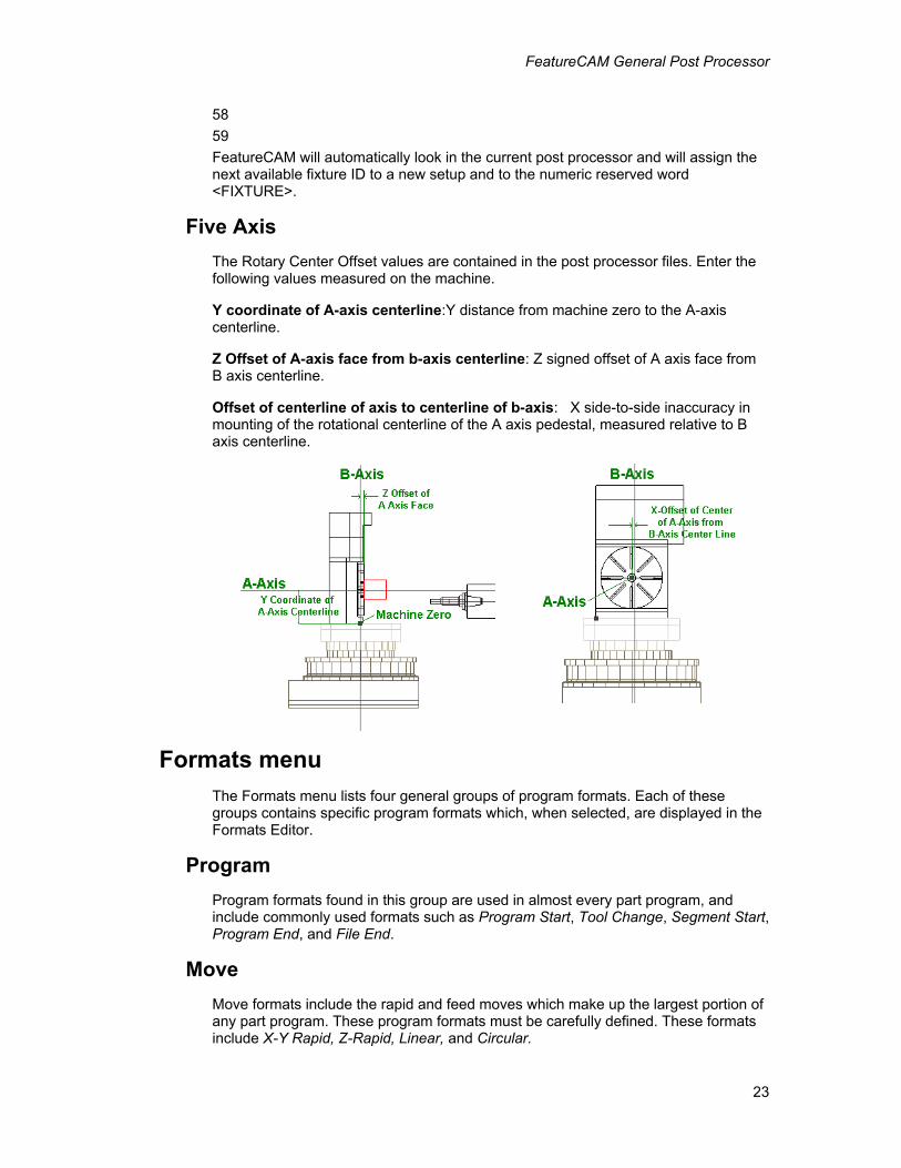
Five Axis The Rotary Center Offset values are contained in the post processor files. Enter the following values measured on the machine.
Y coordinate of A-axis centerline:Y distance from machine zero to the A-axis centerline.
Z Offset of A-axis face from b-axis centerline: Z signed offset of A axis face from B axis centerline.
Offset of centerline of axis to centerline of b-axis: X side-to-side inaccuracy in mounting of the rotational centerline of the A axis pedestal, measured relative to B axis centerline.
Formats menu The Formats menu lists four general groups of program formats. Each of these groups contains specific program formats which, when selected, are displayed in the Formats Editor.
Program Program formats found in this group are used in almost every part program, and include commonly used formats such as Program Start, Tool Change, Segment Start, Program End, and File End.
Move Move formats include the rapid and feed moves which make up the largest portion of any part program. These program formats must be carefully defined. These formats include X-Y Rapid, Z-Rapid, Linear, and Circular.
FeatureCAM General Post Processor
24
Macro Macro formats include the Open Macro, Close Macro, Macro Call, In-Macro Linear, and In-Macro Circular formats. These formats do not need to be defined if the target control does not use macros.
Cycle Cycle formats include most of the canned cycles which are found in many controls. These cycles also use specific reserved words which are discussed in detail below. The Cycle formats include Drill, Deep Hole, Tap, Bore (F-F), Chip Break, Cycle Cancel, and Canned Move.
XBUILD program formats For each segment of a part program, parameters and calculated values are passed via Reserved Words from the program formats' definitions. These program formats act as a template; they are sequentially filled (i.e., Reserved Words are substituted by their corresponding values, G and M codes) as the part data file is post processed.
Making reserved words modal
In some cases, the CNC machine uses modality to avoid redundant data to reduce the length of the program. Under modality, repeated coordinates or commands are “stripped” from the part program. String and numeric-type Reserved Words may be surrounded by modality delimiters ({ }) to signal Post to remove redundant data. The modality delimiter prevents a repetitive occurrence of a Reserved Word as long as its value remains the same as the previous occurrence.
For example, when modality delimiters are used in {<SEQ>}, you have the option of “stripping” all sequence numbers from the program during post processing. This is accomplished by specifying 0 for the start and sequence step numbers in Post. This forces the sequence numbering to remain the same.
Defining program formats
1. As Post reads each segment from the part data file, it determines if it is the first segment of the program, a tool change, or a non-tool changing segment.
2. Based upon this information, Post outputs the appropriate segment block (i.e., PROGRAM START, TOOL CHANGE, or SEGMENT START) prior to executing segment data.
3. Only one of these three program formats is used at the beginning of any one segment.
NOTE: Each definition can include multiple lines, and each line must end with <EOB>.
Rules
1. The Reserved Words, <X-COORD> and <Y-COORD> are the assigned values of the first path point, and must appear in all program formats to provide the first positioning move to the start of the path.
2. It is mandatory that the Reserved Word, <Z-COORD> be used for the SEGMENT START program format. It is calculated as the largest Z Rapid value of the
FeatureCAM General Post Processor
25
current and previous segments, thereby allowing for the tool to be retracted from the part, to a safe plane.
3. Use of the <Z-COORD> Reserved Word is optional for PROGRAM START and TOOL CHANGE program formats. It is calculated in the following manner:
• <Z-COORD> = TL CHG (Z)
• TL CHG (Z) is programmed in FeatureCAM
4. Whether <Z-COORD> is used or not, Post assumes that the tool is at this Z level, after the code for any of the aforementioned formats is generated.
NOTE: The TOOL CHANGE format is output only if there is a change in tool number between segments. If there is not a change in tool number, the SEGMENT START format is output.
Program start rules
1. Post outputs lines that are defined in PROGRAM START at the beginning of a program. In PROGRAM START, general preparatory codes (e.g., absolute, incremental, etc.) are placed to define the dimension system.
2. The first tool change must also be defined.
3. Functions such as, <SPEED>, <SPINDLE> and <COOLANT> status can be passed to the Post output with the first positioning move via <X-COORD> and <Y-COORD>.
4. If the target machine tool uses fixture offsets (G54, G55/E1, E2), the Reserved Word <FIXTURE> should be positioned before the <MOTION> <X COORD> and <YCOORD> words.
Tool change rules
1. A TOOL CHANGE block is output between segments that require a tool change.
2. This block is only output if the Tool # specification (FeatureCAM) differs from the previous one.
3. Functions such as, <SPEED>, <SPINDLE> and <COOLANT> status can be passed to the Post output with the first positioning move via <X-COORD> and <Y-COORD> Reserved Words.
4. If the target machine tool uses fixture offsets (G54, G55/E1, E2), the Reserved Word <FIXTURE> should be positioned before the <MOTION> <X COORD> and <YCOORD> words.
Segment start rules
1. SEGMENT START is only output between non-tool changing segments.
2. SEGMENT START should contain any commands that may change between segments (e.g., <SPEED>, <COOLANT>, etc.).
3. The Reserved Words: <X-COORD>, <Y-COORD> and <Z-COORD>, must be included in SEGMENT START.
4. If the target machine tool uses fixture offsets (G54, G55/E1, E2), the Reserved
FeatureCAM General Post Processor
26
Word <FIXTURE> should be positioned before the <MOTION> <X COORD> and <YCOORD> words.
Program end
This block can be used to: turn the Coolant Off; position the tool to an endpoint; and rewind the part program.
1. Using the Reserved Words, <X-CHANGE> and <Y-CHANGE> positions the tool at the last tool change point.
2. For incremental programming, type the @ symbol in front of these Reserved Words (e.g., <@X-CHANGE>) to move to the first tool change position in the part program.
Defining move formats
There are four move formats:
• X, Y Rapid Move
• Z Rapid Move
• Linear Move
• Circular Move
Depending on the control, one of two cases is true for these program formats.
1. If the CNC requires X, Y and Z axes motion to be programmed in the same rapid line, then all three Reserved Words (X, Y and Z) must be included in the X,Y RAPID MOVE program format. The Z RAPID MOVE format must remain empty.
2. If the CNC does not allow for X, Y and Z axes motion to be programmed in the same rapid line, then use both (the X,Y RAPID MOVE and Z RAPID MOVE) formats.
NOTE: The order in which moves are generated depends upon whether the current Z position is greater, or less than the previous Z position.
X,Y Rapid Move
X,Y Rapid Move defines the output format for rapid positioning moves. Generally, modality delimiters ({}) are placed around the <X-COORD> and <Y-COORD> Reserved Words. This allows the postprocessor to “strip” X, or Y from the line when a coordinate is redundant. If the first case is true (see cases following the Z RAPID MOVE format), then the <Z-COORD> Reserved Word must be included.
Z Rapid Move
Z Rapid Move If the first case is true, then the Z RAPID MOVE program format must remain empty. If the second case is true, then the <Z-COORD> Reserved Word must be included.
Linear Move
Linear Move defines the output format for linear moves. The following Reserved Words must be defined in this block: <X-COORD>, <Y-COORD>, <Z-COORD>,
FeatureCAM General Post Processor
27
<FEED> and <MOTION>. Cutter diameter compensation can be turned ON/OFF in this format line via the <COMP-START> Reserved Word.
Some CNC machines may require the use of the vector Reserved Words, <X-VECTOR> and <Y-VECTOR>.
Circular Move
Circular Move The following Reserved Words are provided as arc modifiers for I, J, or R values: <ARC-X>, <ARC-Y>, <RADIUS>, <S-RAD>, <X-CEN>, or <Y-CEN>.
File end
File End specifies the format of a line(s) to be placed at the end of a file. This is generally used with the END OF PROG specification (GENERAL INFO, MACRO TYPE).
Incremental programming rules
The following information explains the rules for building postprocessors for controls that only support incremental input.
Each occurrence of the following Reserved Words must be in the specified form in PROGRAM FORMATS:
Reserved Word Form
<X-CHANGE> <@X-CHANGE>
<Y-CHANGE> <@Y-CHANGE>
<X-COORD> <@X-COORD>
<Y-COORD> <@Y-COORD>
<Z-COORD> <@Z-COORD>
The PROGRAM START format may not contain any of the following Reserved Words: <@X-CHANGE>, <@Y-CHANGE>, or <@Z-COORD>. This is assuming that the first tool has been positioned at the start point (the first segment's tool change position) by the operator before starting the NC part program.
The PROGRAM END format must contain the Reserved Words, <@X-CHANGE> and <@Y-CHANGE> to reposition the tool back to the start point.
Using FeatureMILL or FeatureMILL3D and XBUILD This section explains how the parameters that are defined in milling correspond to XBUILD Reserved Words, and how these are handled when NC is pressed.
Input dimension If the units of your post and the post processor are different, a conversion factor is automatically applied to them at the time the program is posted.
Cycle types The operations in FeatureCAM are mapped to the following canned cycle formats:
FeatureCAM General Post Processor
28
Operation Canned Cycle Format
Chamfer SPOT FACE Countersink SPOT FACE Counterbore SPOT FACE Drill DRILL
Ream BORE(F-F)
Tap TAP
Peck Drilling DEEP HOLE and CHIP BREAK
The following FeatureCAM parameters contain corresponding Reserved Words in XBUILD:
FeatureCAM BUILD TYPE
Tool No.(from Operations Sheet
<TOOL> Numeric
Fixture ID <FIXTURE> Numeric
Tool Change Location X (from Post Options dialog box)
<X-CHANGE> Numeric
Tool Change Location Y (from Post Options dialog box)
<Y-CHANGE> Numeric
Tool Change Location Z (from Post Options dialog box)
<Z-COORD> Numeric
Coolant Manufacturing Attribute (Default Attribute or Feature Attribute)
<COOLANT> String
Some CNC machines require the previous Tool # and Fixture #. In this case, use the $symbol to represent the previous number. Tool parameter lines are formatted in PROGRAM START, TOOL CHANGE and PROGRAM END program formats.
Coolant parameters (Off, Mist and Flood) are defined in XBUILD, and are output by Post whenever the Reserved Word, <COOLANT> appears in a program format block.
Z data XBUILD has a Reserved Word for each Z parameter in FeatureCAM. XBUILD also provides words that signal Post to perform arithmetic operations to accommodate the different ways that machines handle the Z axis. The following manufacturing attributes in FeatureCAM contain corresponding Reserved Words in XBUILD:
FeatureCAM BUILD TYPE
FeatureCAM General Post Processor
29
Z Rapid Plane <ZRAPID> Numeric
Plunge Clearance <ZCLEAR> Numeric
Handling cutter compensation Cutter compensation is handled by XBUILD and can be configured several ways, depending upon the CNC requirements. The most common configuration is to turn compensation On in the first X-Y feed move of the cutter path, and turn compensation Off in the last X-Y feed move. If the aforementioned configuration is utilized, then define the LINEAR MOVE program format as follows:
LINEAR MOVE BLOCK
{N<SEQ>}{<COMP-STAT>}{<MOTION>}{X<X-COORD>}{Y<Y-COORD>}{Z<Z-COORD>}{F<FEED>}<EOB>
If it is necessary to output the vector direction of the next move (for Cincinnati Milacron controls only), use the <X-VECTOR> and <Y-VECTOR> Reserved Words.
Other configurations may require the X and Y coordinates to be repeated as compensation is turned On. In that case, establish a conditional statement so that these repeated coordinates do not appear in every linear move of the cutter path. A conditional statement for a LINEAR MOVE program format is as follows:
LINEAR MOVE BLOCK
<IF><COMP-ON><THEN>
{N<SEQ>}<COMP-STAT>X<$X-COORD>Y<$Y-COORD><EOB>
<ENDIF>
{N<SEQ>}{<COMP-STAT>}{<MOTION>}{X<X-COORD>}{Y<Y-COORD>}{Z<Z-COORD>}{F<FEED>}<EOB>
The $ symbol is a Reserved Word modifier to generate the previous values of X and Y (to represent the current position of the tool). The <X-COORD> and <Y-COORD> Reserved Words always represent the next point in the cutter path.
Handling Pecking Pecking applies to Deep Hole, Chip Break and Tap operations. The first step to handling pecking in a CNC file is to set the type of pecking that will be used for drilling and tapping on the NC Codes page. FeatureCAM checks the pecking type in the currently loaded post processor to duplicate canned cycles when simulating toolpaths. The second step is to create the appropriate program formats for the canned cycles based on the pecking type.
Fixed steps
The NC code specifies one depth and all the steps peck at that depth. An example would be the deep hole cycle of the Fanuc 0m:
{N<SEQ>}<CYCLE>{X<X-COORD>}{Y<Y-COORD>}R<ABS-ZCLEAR>Z<ABS-DEPTH>Q<STEP1>F<FEED><EOB>
Two steps
FeatureCAM General Post Processor
30
The NC code specifies two depths. The first step pecks at the first depth and all the subsequent steps peck at the second depth. The Bridgeport Machines Boss9I control deep hole cycle is an example
.{N<SEQ>}<CYCLE>Z<INC-DEPTH>Z<INC-STEP1>Z<STEP2>F<FEED><EOB> {N<SEQ>X<X-COORD><EOB>
Value reduction
The NC code specifies the first depth, a reducing value and a minimum depth. The first step pecks at the first depth. Each subsequent step is reduced by the reducing value until the minimum depth is reached. To use the FeatureCAM attributes consistently with the other pecking methods, it is recommended that the reducing value be calculated with the expression, [<STEP1>-<STEP2>] as shown in the deep hole drilling cycle for the Fadal control below:
{N<SEQ>}<CYCLE>{X<X-COORD>}{Y<Y-COORD>}R<ABS-ZCLEAR>Z<ABS-DEPTH>I<INC-STEP>
J<[<STEP1>-<STEP2>]K<MIN-STEP>F<FEED><EOB>
Factor reduction
The NC code specifies the first depth, a reducing factor and a minimum depth. The first step pecks at the first depth. Each subsequent step is reduced by the reducing factor until the minimum depth is reached. To use the FeatureCAM attributes consistently with the other pecking methods, it is recommended that the reducing value be calculated with the expression, [<STEP2>/<STEP1>] as shown in the deep hole drilling cycle for the GE2000 control below:
{N<SEQ>}<CYCLE>Z<ABS-DEPTH>R<ABS-ZCLEAR>D<TOOL>F<FEED> P1=<INC-STEP1>
P2=[<STEP2>/<STEP1>]P5=<MIN-STEP>F<FEED><EOB>
{N<SEQ>} X<X-COORD>Y<Y-COORD><EOB>
Handling multiple fixture documents To use the multiple fixture document capability of FeatureCAM, the reserved word <FIXTURE> or <MCSID> must be placed in the program start, tool change and segment start program formats prior to any <MOTION> statements. Your choice of <FIXTURE> or <MCSID> depends on your programming preference and the type of controller being used. Generally one or the other reserved word is used, not both. When the reserved word <FIXTURE> is used, it is preceded by the controller’s fixture offset letter (e.g. ‘D’, ‘E’, ‘F’, ‘G’ or ‘H’) in the appropriate program formats. Remember that the reserved word <FIXTURE> is obtained from the Fixture ID of the setup in FeatureCAM.
For example, the following build line is the last line of the program start format of the 850sxm.cnc post.
{N<SEQ>}G0X<X-COORD>Y<Y-COORD>Z<ABS-ZRAPID><COOLANT><EOB>
Adding an ‘H’ command using the <FIXTURE> reserved word prior to the motion command would look like this,
{N<SEQ>}H<FIXTURE>G0X<X-COORD>Y<Y-COORD>Z<ABS-ZRAPID><COOLANT><EOB>
A similar modification to the tool change and segment start program formats would
FeatureCAM General Post Processor
31
complete the necessary changes to the post.
When using the reserved word <MCSID>, recall that this word is the name of the setup in FeatureCAM. This reserved word has more flexibility than the <FIXTURE> reserved word since it is a string. The only requirement is that the setup name in FeatureCAM uses the appropriate G-code command for your post. The placement of the <MCSID> reserved word in the block is identical to that of the <FIXTURE> reserved word only it does not need a preceding command letter. Using the above example, the modification would be,
{N<SEQ>}<MCSID>G0X<X-COORD>Y<Y-COORD>Z<ABS-ZRAPID><COOLANT><EOB>
The setup name in this particular example must be of the form "Hx" where x is a number. In controllers that accept specific commands to indicate particular fixture offsets, such as "G54", or "G55", using the <MCSID> reserved word may lessen confusion during the design process.
By placing the reserved word <FIXTURE> or <MCSID> in the program start, tool change, and segment start program formats, the fixture offset is called immediately prior to any motion commands.
When a fixture offset is changed, it is recommended that the <FIXTURE> or <MCSID> reserved word not be surrounded by modal brackets such that the fixture offset is repeated at each tool change or segment start line. This allows the tool change and segment start lines (under appropriate conditions) to used as a possible restart line.
Handling retract planes in canned cycles If the control allows the changing of retract planes during a canned cycle you must adjust the post with the following steps:
1. Enter the G-codes for each rapid plane under Z rapid retract and R plane retract.
2. In the Canned Move and all the Drilling canned cycles, the keyword, <CYCLE-RTRCT> must be included.
For example, for Fanuc, the G98 and G99 g-codes are entered in the NC Codes dialog and a sample drilling cycle would be:
{N<SEQ> }<CYCLE> <CYCLE-RTRCT> Z<ABS-DEPTH> R<ABS-ZCLEAR> F<FEED><EOB> {N<SEQ> }{X<X-COORD>}{ Y<Y-COORD>}<EOB>
Fourth and fifth axis support FeatureCAM supports the use of a rotary table as a fourth axis for indexing between operations and for wrapping, allowing continuous movement of the rotary axis during the cutting operations. Both of these strategies depend on hardware which supports this kind of operation, and the user of post-processor designed to address that hardware.
Fifth axis indexing, known also as fifth axis positioning, is supported in the 5th axis positioning option. If using 4th or 5th axis capabilities you must use different post processors files. For 4th axis indexing or wrapping use a post in the 4thxs directory.
FeatureCAM General Post Processor
32
For 5th axis positioning, use a post in the 5thxs directory.
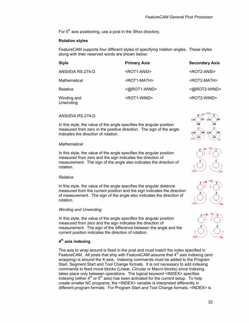
Rotation styles
FeatureCAM supports four different styles of specifying rotation angles. These styles along with their reserved words are shown below:
Style Primary Axis Secondary Axis
ANSI/EIA RS-274-D <ROT1-ANSI> <ROT2-ANSI>
Mathematical <ROT1-MATH> <ROT2-MATH>
Relative <@ROT1-WIND> <@ROT2-WIND>
Winding and Unwinding
<ROT1-WIND> <ROT2-WIND>
ANSI/EIA RS-274-D
In this style, the value of the angle specifies the angular position measured from zero in the positive direction. The sign of the angle indicates the direction of rotation.
Mathematical
In this style, the value of the angle specifies the angular position measured from zero and the sign indicates the direction of measurement. The sign of the angle also indicates the direction of rotation.
Relative
In this style, the value of the angle specifies the angular distance measured from the current position and the sign indicates the direction of measurement. The sign of the angle also indicates the direction of rotation.
Winding and Unwinding
In this style, the value of the angle specifies the angular position measured from zero and the sign indicates the direction of measurement. The sign of the difference between the angle and the current position indicates the direction of rotation.
4th axis indexing
The axis to wrap around is fixed in the post and must match the index specified in FeatureCAM. All posts that ship with FeatureCAM assume that 4th axis indexing (and wrapping) is around the X-axis. Indexing commands must be added to the Program Start, Segment Start and Tool Change formats. It is not necessary to add indexing commands to feed move blocks (Linear, Circular or Macro blocks) since indexing takes place only between operations. The logical keyword <INDEX> specifies indexing (either 4th or 5th axis) has been activated for the current setup. To help create smaller NC programs, the <INDEX> variable is interpreted differently in different program formats. For Program Start and Tool Change formats, <INDEX> is
FeatureCAM General Post Processor
33
true if indexing is enabled in FeatureCAM. For Segment Start formats, <INDEX> is true only if indexing is enabled in FeatureCAM and the machine tool is performing the actual indexing move.
This example is the Segment Start format from the a Bridgeport control that supports 4th axis. The <Z-INDEX-CLR> is a Z clearance value calculated from the maximum Z coordinate of the part (or parts if using Tombstone machining) plus the Z Index Clearance default attribute.
'<SEGM-ID>'<EOB>
{'COMMENT:<SEG-CMT>'}<EOB>
{N<SEQ>}F<FEED><EOB>
{N<SEQ>}{<MOTION>}{Z<Z-COORD>}<COOLANT><EOB>
{N<SEQ>}{S<SPEED>}{<SPINDLE>}<EOB>
{N<SEQ>G97}{X<SHIFTX>}{Y<SHIFTY>}{Z<SHIFTZ>}{<EOB>}
<IF><INDEX><THEN>
{N<SEQ>}Z<Z-INDEX-CLR><EOB> {N<SEQ>}M51; INDEX <ROT1-MATH><EOB>
<ENDIF>
{N<SEQ>}<MOTION>X<X-COORD>Y<Y-COORD>{Z<Z-COORD>}<COOLANT><EOB>
Wrapping
4th axis wrapping in FeatureCAM causes rotary motion of the part, while the tool is cutting. A simple example of this might be engraving letters on the outside of a cylinder. However, FeatureCAM can wrap any feature, including surface milling features around the fourth axis.
To support wrapping, a test for the logical word <WRAP> and the necessary lines should be added to the Program Start, Tool Change and Segment Start formats as well as the feed formats (Linear and In_Macro Linear). It is not necessary to add the fourth axis support blocks to the circular move formats since all arc moves are broken into linear moves when the wrap feature is enabled.
The following is an example of a Linear program format for a Bridgeport Torq-Cut mill that wraps around the Y axis. Note that in the wrapping case, a rotation is used for what would be a Y move in the non-wrapping case.
<IF><COMP-START><THEN>
{N<SEQ>}<COMP-STAT>X<$X-COORD>Y<$Y-COORD><EOB>
<ENDIF>
<IF><WRAP><THEN>
{N<SEQ>}{<MOTION>}{X<X-COORD>}{C<ROT1-MATH>}{Z<Z-COORD>}{F<ANG-FEED>}<EOB>
<ENDIF>
<IFNOT><WRAP><THEN>
{N<SEQ>}{<MOTION>}{<COMP-STAT>}{X<X-COORD>}{Y<Y-COORD>}{Z<Z-COORD>}{F<FEED>}<EOB>
FeatureCAM General Post Processor
34
<ENDIF>
Wrapping requires special consideration in the Rapid move block. To prevent a collision between the tool and part during rotation, the tool must be withdrawn from the part before the rotation takes placed. Since the control does not normally test for this case, XBUILD includes two logical reserved words which are used only to test for the wrap setting and the rapid move condition. The rapid move block then includes both of these words (<WRAP-Z-UP> and <WRAP-Z-DOWN>) and is implemented in this way:
<IF><WRAP-Z-DOWN><THEN>
{N<SEQ>}{<MOTION>}{C<ROT1-MATH>}<EOB>
{N<SEQ>}{X<X-COORD>}{<COOLANT>}<EOB>
{N<SEQ>}{Z<Z-COORD>}<EOB>
<ENDIF>
<IF><WRAP-Z-UP><THEN>
{N<SEQ>}{<MOTION>}{Z<Z-COORD>}<EOB>
{N<SEQ>}{C<ROT1-MATH>}<EOB>
{N<SEQ>}{X<X-COORD>}{<COOLANT>}<EOB>
<ENDIF>
<IFNOT><WRAP><THEN>
{N<SEQ>}{<MOTION>}{X<X-COORD>}{Y<Y-COORD>}{Z<Z-COORD>}{<COOLANT>}<EOB>
<ENDIF>
5th axis indexing
Fifth axis indexing allows 2 ½ D or 3D toolpaths to be performed from many orientations. For 5th axis positioning, use a post in the 5thxs directory. Indexing commands must be added to the Program Start, Segment Start and Tool Change formats. It is not necessary to add indexing commands to feed move blocks (Linear, Circular or Macro blocks) since indexing takes place only between operations. The logical keyword <INDEX> specifies indexing (either 4th or 5th axis) has been activated for the current setup. To help create smaller NC programs, the <INDEX> variable is interpreted differently in different program formats. For Program Start and Tool Change formats, <INDEX> is true if indexing is enabled in FeatureCAM. For Segment Start formats, <INDEX> is true only if indexing is enabled in FeatureCAM and the machine tool is performing the actual indexing move.
The following is the Segment Start program format is for the Fanuc 16 control:
<IF><INDEX><THEN> {N<SEQ>}{<MOTION>}G53G90G00G80G49Z0M11M71<EOB> <10><13> {N<SEQ>}{<MOTION>}{X<X-COORD>}A<ROT1-WIND>B<ROT2-WIND>M10M70<EOB> <ENDIF> <IF><WRAP><THEN> {N<SEQ>}{<MOTION>}{X<X-COORD>Y0}{A<ROT1-WIND>}{Z<Z-COORD>}{<COOLANT>}<EOB> <ENDIF> <IFNOT><WRAP><THEN>
FeatureCAM General Post Processor
35
{N<SEQ>}{<MOTION>}{Z<Z-COORD>}{<COOLANT>}<EOB> {N<SEQ>}{<MOTION>}{X<X-COORD>}{Y<Y-COORD>}<EOB> <ENDIF> {N<SEQ>}S<SPEED>F<FEED><EOB>
3D arcs 3-axis techniques that produce toolpaths in the principle planes can approximate the them with 3D lines and arcs. To activate this option, check the Arc/line approx milling attribute. To output the proper g-codes, the post must support 3D arcs. The proper g-codes for each circular plane must be entered in the NC Codes dialog box. These g-codes are stored in the <PLANE> reserved word. The Circular Move format must also be augmented to support arcs in each plane. The logical variables <XY-PLANE>, <ZX-PLANE>, and <YZ_PLANE> distinguish the plane of the current arc. The following is a Circular Move format for 3D arcs. The major purpose of the various cases is to output the correct arc centers.
{N<SEQ>}{<PLANE>}<MOTION> <IF><XY-PLANE><THEN> X<X-COORD>Y<Y-COORD>{Z<Z-COORD>}I<X-CEN>J<Y-CEN> <ENDIF> <IF><ZX-PLANE><THEN> Z<Z-COORD>X<X-COORD>{Y<Y-COORD>}K<Z-CEN>I<X-CEN> <ENDIF> <IF><YZ-PLANE><THEN> Y<Y-COORD>Z<Z-COORD>{X<X-COORD>}J<Y-CEN>K<Z-CEN> <ENDIF> {F<FEED>}<EOB>
Turning general post processor
CNC info menu General
When General is selected, a list of options pertaining to the output program format displays. Any parameter may be changed by selecting it, typing the value, or toggling to the desired selection (if a new value is entered, press Enter).
Machine Type
The Machine type classifies the type of post. The choices are
• Milling – use this type of post for 2.5D or 3D milling.
• Turning – use this classification for 2-axis turned parts
• Turn/MILL – use this type of post for lathe with powered rotary tools.
FeatureCAM General Post Processor
36
This distinction controls type of reserved words and program formats that are available in the post.
Dimension
Dimension toggles between Inch and Metric output. Post uses the selection to convert the dimensions that affect X and Y coordinates as well as feed rate. The setting in the CNC Data file takes precedence over the assumed inch unit in FeatureCAM. If a part program is written in inch units, and is processed with a metric CNC data file, the resulting part program is converted (using standard conversion constants) into metric units.
EOB
EOB defines the end of block character(s) (<EOB>). It is recommended that the default characters be used (i.e., <13><10>, carriage return and line feed).
Decimal Point
Decimal Point defines the decimal point character. This character is usually a period (.) for United States controls, and a comma (,) for European controls.
Circ. Interpol.
Circ. Interpol. toggles between Multi-Quadrant and Single Quadrant and specifies the programming format on the CNC for which the postprocessor is being built. For example, if the Numerical Control cannot drive an arc across a quadrant line (plus or minus X and Y axes), then select Single Quadrant circular interpolation.
Tool Ln Comp
This option allows for the compensation of tool length by subtracting the tool's X and Z length from the coordinate data at postprocessing time. Using Tool Ln Comp allows the user to shift or compensate for different tool lengths without presetting the origin for each tool. For Japanese machines such as FANUC, this selection should be turned Off. If the output is to be incremental, Tool Ln Comp must be turned On.
NC File Ext.
This is the default file extension for you CNC programs. For example if it is set to “.txt”, and your part is called “bracket”, then the gcode file will be called “bracket.cnc”.
Motion & Compensation
With the Motion-Compensation dialog, the exact character strings that are required
Commands by the NC machine for different motion types can be specified. For example, LINEAR is generally defined as G1, but may be changed to G01, or any other string (up to eight characters). All motion commands are passed to Post via the string-type Reserved Word, <MOTION>.
Tool tip radius compensation may be generated in the output when turned On in FeatureTURN, and if it is built into the CNC BUILD file. COMPENSATION selections use the string-type Reserved Word, <COMP-STAT> for one of the strings shown above, or an empty string is assigned if the Compensation option was not turned On in FeatureTURN.
Pecking types are the types of pecking performed for drilling and tapping.
FeatureCAM General Post Processor
37
Turret Info
This command is used to specify various data required by the control for the particular turret being used. When this command is selected, a dialog box is displayed in which several codes need to be specified.
Parameters 1-5 are used to specify the turret select, coolant and turret direction codes that are required by the machine. The string-type Reserved Words that correspond to these selections are displayed on the right (above).
<COOLANT-OFF> should usually be used at the beginning of a TOOL CHANGE, SEGMENT START and PROGRAM END configuration to turn off coolant used in the previous segment. <COOLANT-ON> should be specified after <COOLANT-OFF> to turn coolant On for the next segment. If no coolant was used, then the value of <COOLANT-OFF>, or <COOLANT-ON> is an empty string.
Some two turret lathes may require negative X coordinate data to be output to drive the secondary turret below the center line. Turning X SIGN REV On for a particular turret signals Post to reverse the sign of X coordinates while this turret is being used.
All programming in FeatureTURN remains above the spindle center line.
Z BTW TRT (Turret Info)
X BTW TRT
Z and X distances between turrets are signed values measured from the primary turret reference point to the secondary turret reference point. The turret reference points are always the locations from which the tool lengths are measured.
Feeds and Speeds
These parameters are used to specify the spindle direction, feed units and the speed range codes that are required by the machine:
FEED MAX and MIN are the feed rate limits when specified in Feed Per Minute.
DEGREES/MINUTE Max and MIN are the feed rate limits when specified in Degrees Per Minute.
RANGE 1- RANGE 4 are for lathes that have ranges. For each range, enter the M-codes for selecting the range and the Max. speed for the range.
UPM (Units per Minute) and UPR (Units per Revolution) describe the feed rate in terms of UPM or UPR (or the spindle). Only one option at a time is used by Post, depending upon FeatureTURN's segment data.
SPINDLE CW (clockwise) and SPINDLE CCW (counter-clockwise) describe the spindle On and direction code. Both of these selections use the string-type Reserved Word <SPINDLE> to specify spindle On and direction.
* NOTE *
Spindle Dir is specified in FeatureTURN with a negative, or positive spindle RPM value. A negative value specifies a CCW direction, while a positive value specifies a CW direction.
When CSS is turned on in FeatureTURN, the spindle speed is limited to the
FeatureCAM General Post Processor
38
maximum set for the appropriate speed range set here.
Cycles Info
The following options contained in CYCLES INFO allow for specifying the manner in which drilling and threading cycles are handled.
These selections toggle between CANNED and COMPUTED. When CANNED is selected, a format for a canned threading, drilling, or grooving cycle is defined, which is output by Post only one time. If COMPUTED is chosen, the drilling, threading, or grooving move definitions are output as the respective cycle's pass for each step.
Grooving has only limited canned cycle support. Only roughing of straight-walled grooves are output as a canned cycle. This applies to grooves with Chamfer = 0, Angle = 0 and Radius = 0.
NUMERIC-TYPE RESERVED WORDS
Numeric-type Reserved Words are replaced by their numeric values when Post is executed. For example, the numeric-type Reserved Word <X-COORD> is replaced by the current X axis coordinate position. Each numeric Reserved Word contains a corresponding Words Tables record to specify its output format (see "Words Tables" in this chapter for more information).
IMPORTANT
Numeric Reserved Words can be preceded by the symbols $, or @ (<$ name>, or <@ name>). The $ prefix signals Post to output the previous value of a Reserved Word. The @ prefix signals Post to output an incremental value (the difference between the current value and the previous value).
Numeric General Words
<SEQ> This is a line sequence number identifier (when the word appears in a line, it is substituted with the current sequence number, and is subsequently incremented by the sequence step value)
<Z-COORD> Z axis coordinate identifier
<X-COORD> X axis coordinate identifier
<COMP-NUM> Compensation number passed from FeatureTURN
<SPEED> Spindle RPM value passed from FeatureTURN parameters
<TOOL> Tool number passed from FeatureTURN. Corresponds to the Tool column of the Tool Mapping Dialog box.
<NEXT-TL> Next tool to be used, may be required by some controls. Corresponds to the Tool column of the Tool Mapping Dialog box.
<CSS-SPEED> Corresponds to Surface Speed parameter on the Feed/Speed tab of a feature.
<SP-MAX> Maximum spindle RPM when CSS is ON, used to set the maximum RPM at which the spindle should run. Corresponds to CSS Max RPM turning attribute or the Max. speed for the current range specified on
FeatureCAM General Post Processor
39
the Feed and Speed dialog box of XBUILD.
<OFFSET#> Tool length offset number. Corresponds to the Offset parameter in the Tool Mapping Dialog Box.
<R-CSS> Radius value in constant surface speed; in Post, this value is set to the first X coordinate value
<CALC-SPEED> Calculated direct RPM speed at the path's start point; the spindle can be turned ON, or readjusted in direct RPM prior to rapid traversing to the path's start point, where CSS is turned ON. The <CALC-SPEED> Reserved Word can be used to automatically calculate the direct RPM "turn on" speed (to turn on CSS after position moves), which avoids rapid traversing to and from a remote indexing point in the CSS mode.
<Z-INDEX> Z-Index turret position passed from FeatureTURN. Corresponds to the Z coordinate of the Tool Change Location (either the Turning attribute or the setting in the Post Options dialog box.
<X-INDEX> X-Index turret position passed from FeatureTURN. Corresponds to the X coordinate of the Tool Change Location (either the Turning attribute or the setting in the Post Options dialog box.)
<Z-PRESET> Distance between the tool program point and the part origin when at the index position along the Z axis; this value is calculated by Post as:
<Z-PRESET> = <Z-INDEX> + <Z TOOL LENGTH> – <distance btw turrets> (<distance btw turrets> is equal to zero for primary turret)
<X-PRESET> Distance between the tool program point and the part origin when at the index position along the X axis; this value is calculated by Post as:
<X-PRESET> = <X-INDEX> + <X TOOL LENGTH> – <distance btw turrets> (<distance btw turrets> is equal to zero for primary turret)
<Z-RETURN> Z coordinate of the previous Z-PRESET value plus any differences between tool change locations; this value is calculated by Post as:
<Z-RETURN> = <$Z-PRESET> + <Z-INDEX> – <$Z-INDEX>
<X-RETURN> X coordinate of the previous X-PRESET value plus any differences between tool change locations; this value is calculated by Post as:
<X-RETURN> = <$X-PRESET> + <X-INDEX> – <$X-INDEX>
<FEED-UPR> Format of this word is used to pass feed rate value and/or the Reserved Word <FEED> Use IPR is checked on the Feed/Speed tab for a feature.
<FEED-UPM> Format of this word is used to pass feed rate value and/or the Reserved Word <FEED> when Use IPR is not checked on the Feed/Speed tab for a feature.
<FEED> Passes the feed rate value to the word format of <FEED-UPM> or <FEED-UPR>, depending upon the Feed Units specified in FeatureTURN
FeatureCAM General Post Processor
40
<DWELL> Corresponds to Dwell parameter for Cutoff, Groove, and Tapping.
<TL-WIDTH> Width of selected tool.
<STEPOVER> For groove only. Corresponds to Stepover % * Tool Width.
<ENG-ANGLE90> Engage Angle for turning or 90 + Engage Angle for boring.
<CLEARANCE> Corresponds to the clearance attribute.
<CLR-DEPTH> <CLEARANCE> + <DEPTH>.
<LIFT-OFF> For groove only. Corresponds to Liftoff Dist. Attribute.
<SPINDLE-POS> Sub-spindle position.
Numeric Circular Block Words
<ARC-Z> Used in the circular interpolation block to specify the signed Z
distance from the start point of the arc to the center of the arc, along the Z axis
<ARC-X> Used in the circular interpolation block to specify the signed X distance from the start point of the arc to the center of the arc, along the X axis
<RADIUS> Reproduces arc radius in a circular block
<S-RAD> Generates the signed arc radius value in a circular block, +R<180 degrees and –R>180 degrees
<Z-CEN> Reproduces the absolute Z coordinate position from the Z axis origin to the arc's center in a circular block
<X-CEN> Reproduces the absolute X coordinate position from the X axis origin to the arc's center in a circular block
* NOTE *
To generate the signed distance from the arc's center to the arc's start position, for <ARC-Z> and <ARC-X> Reserved Words, the FACTR value in Words Tables must be changed to –1. To generate the unsigned distance from the arc's start position to the center of an arc, change the status of UNS_V to ON in Words Tables for these Reserved Words.
Numeric Drilling and Threading Type Cycle Words
<DEPTH> This word has different values for different operations.
• Tap operation: Calculated depth of tap.
• Twist drill operation: Calculated depth of drilling operation including tip.
• Turning, Boring and Face: Depth of Cut
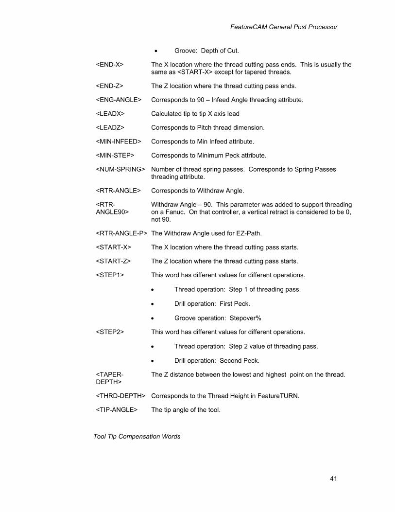
FeatureCAM General Post Processor
41
• Groove: Depth of Cut.
<END-X> The X location where the thread cutting pass ends. This is usually the same as <START-X> except for tapered threads.
<END-Z> The Z location where the thread cutting pass ends.
<ENG-ANGLE> Corresponds to 90 – Infeed Angle threading attribute.
<LEADX> Calculated tip to tip X axis lead
<LEADZ> Corresponds to Pitch thread dimension.
<MIN-INFEED> Corresponds to Min Infeed attribute.
<MIN-STEP> Corresponds to Minimum Peck attribute.
<NUM-SPRING>
Number of thread spring passes. Corresponds to Spring Passes threading attribute.
<RTR-ANGLE> Corresponds to Withdraw Angle.
<RTR-ANGLE90>
Withdraw Angle – 90. This parameter was added to support threading on a Fanuc. On that controller, a vertical retract is considered to be 0, not 90.
<RTR-ANGLE-P> The Withdraw Angle used for EZ-Path.
<START-X> The X location where the thread cutting pass starts.
<START-Z> The Z location where the thread cutting pass starts.
<STEP1> This word has different values for different operations.
• Thread operation: Step 1 of threading pass.
• Drill operation: First Peck.
• Groove operation: Stepover%
<STEP2> This word has different values for different operations.
• Thread operation: Step 2 value of threading pass.
• Drill operation: Second Peck.
<TAPER-DEPTH>
The Z distance between the lowest and highest point on the thread.
<THRD-DEPTH> Corresponds to the Thread Height in FeatureTURN.
<TIP-ANGLE> The tip angle of the tool.
Tool Tip Compensation Words
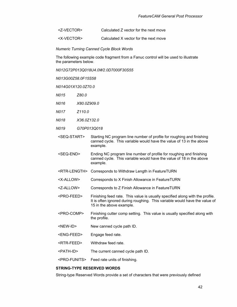
FeatureCAM General Post Processor
42
<Z-VECTOR> Calculated Z vector for the next move
<X-VECTOR> Calculated X vector for the next move
Numeric Turning Canned Cycle Block Words
The following example code fragment from a Fanuc control will be used to illustrate the parameters below.
N012G72P013Q018U4.0W2.0D7000F30S55
N013G00Z58.0F15S58
N014G01X120.0Z70.0
N015 Z80.0
N016 X80.0Z909.0
N017 Z110.0
N018 X36.0Z132.0
N019 G70P013Q018
<SEQ-START> Starting NC program line number of profile for roughing and finishing canned cycle. This variable would have the value of 13 in the above example.
<SEQ-END> Ending NC program line number of profile for roughing and finishing canned cycle. This variable would have the value of 18 in the above example.
<RTR-LENGTH> Corresponds to Withdraw Length in FeatureTURN
<X-ALLOW> Corresponds to X Finish Allowance in FeatureTURN
<Z-ALLOW> Corresponds to Z Finish Allowance in FeatureTURN
<PRO-FEED> Finishing feed rate. This value is usually specified along with the profile. It is often ignored during roughing. This variable would have the value of 15 in the above example.
<PRO-COMP> Finishing cutter comp setting. This value is usually specified along with the profile.
<NEW-ID> New canned cycle path ID.
<ENG-FEED> Engage feed rate.
<RTR-FEED> Withdraw feed rate.
<PATH-ID> The current canned cycle path ID.
<PRO-FUNITS> Feed rate units of finishing.
STRING-TYPE RESERVED WORDS
String-type Reserved Words provide a set of characters that were previously defined
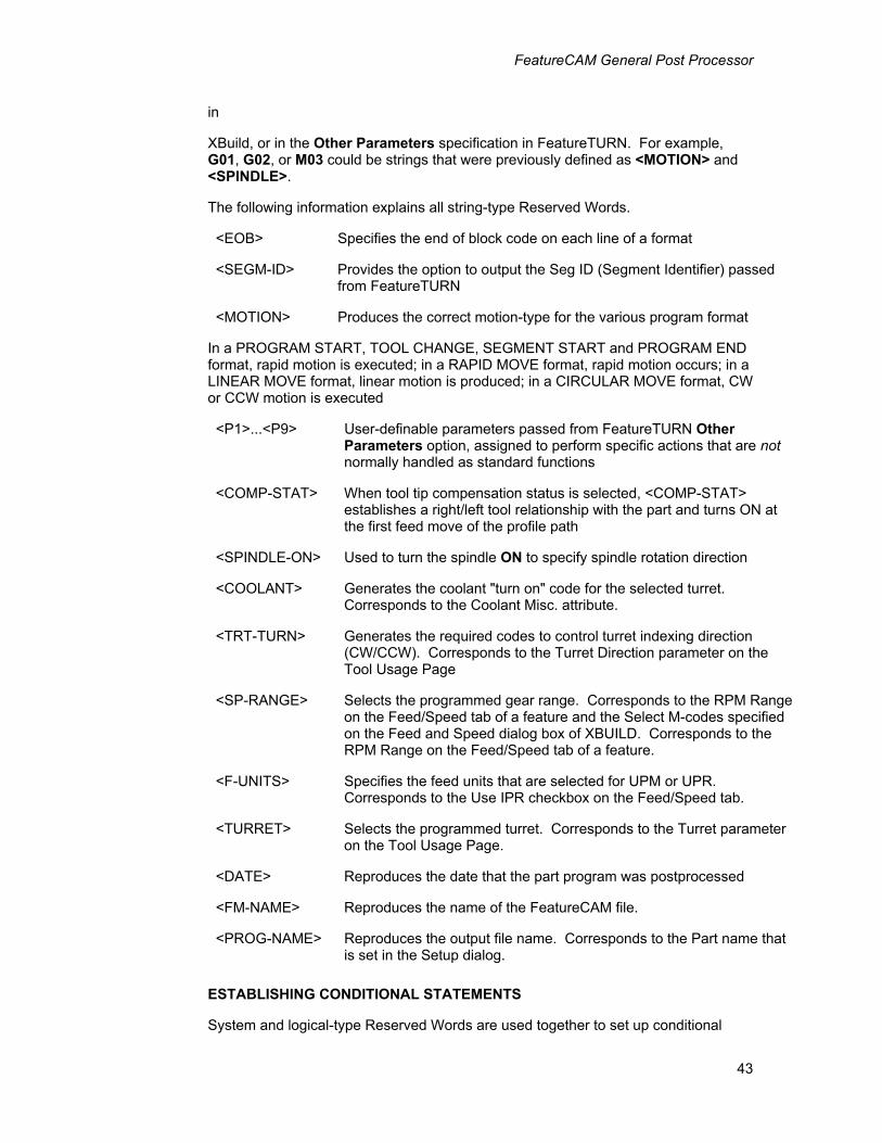
FeatureCAM General Post Processor
43
in
XBuild, or in the Other Parameters specification in FeatureTURN. For example, G01, G02, or M03 could be strings that were previously defined as <MOTION> and <SPINDLE>.
The following information explains all string-type Reserved Words.
<EOB> Specifies the end of block code on each line of a format
<SEGM-ID> Provides the option to output the Seg ID (Segment Identifier) passed from FeatureTURN
<MOTION> Produces the correct motion-type for the various program format
In a PROGRAM START, TOOL CHANGE, SEGMENT START and PROGRAM END format, rapid motion is executed; in a RAPID MOVE format, rapid motion occurs; in a LINEAR MOVE format, linear motion is produced; in a CIRCULAR MOVE format, CW or CCW motion is executed
<P1>...<P9> User-definable parameters passed from FeatureTURN Other Parameters option, assigned to perform specific actions that are not normally handled as standard functions
<COMP-STAT> When tool tip compensation status is selected, <COMP-STAT> establishes a right/left tool relationship with the part and turns ON at the first feed move of the profile path
<SPINDLE-ON> Used to turn the spindle ON to specify spindle rotation direction
<COOLANT> Generates the coolant "turn on" code for the selected turret. Corresponds to the Coolant Misc. attribute.
<TRT-TURN> Generates the required codes to control turret indexing direction (CW/CCW). Corresponds to the Turret Direction parameter on the Tool Usage Page
<SP-RANGE> Selects the programmed gear range. Corresponds to the RPM Range on the Feed/Speed tab of a feature and the Select M-codes specified on the Feed and Speed dialog box of XBUILD. Corresponds to the RPM Range on the Feed/Speed tab of a feature.
<F-UNITS> Specifies the feed units that are selected for UPM or UPR. Corresponds to the Use IPR checkbox on the Feed/Speed tab.
<TURRET> Selects the programmed turret. Corresponds to the Turret parameter on the Tool Usage Page.
<DATE> Reproduces the date that the part program was postprocessed
<FM-NAME> Reproduces the name of the FeatureCAM file.
<PROG-NAME> Reproduces the output file name. Corresponds to the Part name that is set in the Setup dialog.
ESTABLISHING CONDITIONAL STATEMENTS
System and logical-type Reserved Words are used together to set up conditional
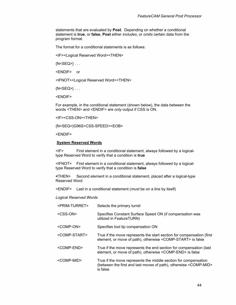
FeatureCAM General Post Processor
44
statements that are evaluated by Post. Depending on whether a conditional statement is true, or false, Post either includes, or omits certain data from the program format.
The format for a conditional statements is as follows:
<IF><Logical Reserved Word><THEN>
{N<SEQ>} . . .
<ENDIF> or
<IFNOT><Logical Reserved Word><THEN>
{N<SEQ>} . . .
<ENDIF>
For example, in the conditional statement (shown below), the data between the words <THEN> and <ENDIF> are only output if CSS is ON.
<IF><CSS-ON><THEN>
{N<SEQ>}G96S<CSS-SPEED><EOB>
<ENDIF>
System Reserved Words
<IF> First element in a conditional statement, always followed by a logical-type Reserved Word to verify that a condition is true
<IFNOT> First element in a conditional statement, always followed by a logical-type Reserved Word to verify that a condition is false
<THEN> Second element in a conditional statement, placed after a logical-type Reserved Word
<ENDIF> Last in a conditional statement (must be on a line by itself)
Logical Reserved Words
<PRIM-TURRET> Selects the primary turret
<CSS-ON> Specifies Constant Surface Speed ON (if compensation was utilized in FeatureTURN)
<COMP-ON> Specifies tool tip compensation ON
<COMP-START> True if the move represents the start section for compensation (first element, or move of path), otherwise <COMP-START> is false
<COMP-END> True if the move represents the end section for compensation (last element, or move of path), otherwise <COMP-END> is false
<COMP-MID> True if the move represents the middle section for compensation (between the first and last moves of path), otherwise <COMP-MID> is false
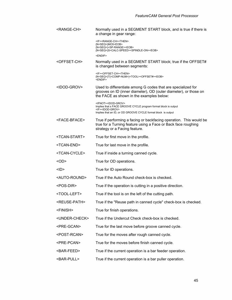
FeatureCAM General Post Processor
45
<RANGE-CH> Normally used in a SEGMENT START block, and is true if there is a change in gear range:
<IF><RANGE-CH><THEN> {N<SEQ>}MO5<EOB> {N<SEQ>}<SP-RANGE><EOB> {N<SEQ>}S<CALC-SPEED><SPINDLE-ON><EOB>
<ENDIF>
<OFFSET-CH> Normally used in a SEGMENT START block; true if the OFFSET# is changed between segments:
<IF><OFFSET-CH><THEN> {N<SEQ>}T{<COMP-NUM>}<TOOL><OFFSET#><EOB> <ENDIF>
<IDOD-GROV> Used to differentiate among G codes that are specialized for grooves on ID (inner diameter), OD (outer diameter), or those on the FACE as shown in the examples below:
<IFNOT><IDOD-GROV> Implies that s FACE GROOVE CYCLE program format block is output <IF><IDOD-GROV> Implies that an ID, or OD GROOVE CYCLE format block is output
<FACE-BFACE> True if performing a facing or backfacing operation. This would be true for a Turning feature using a Face or Back face roughing strategy or a Facing feature.
<TCAN-START> True for first move in the profile.
<TCAN-END> True for last move in the profile.
<TCAN-CYCLE> True if inside a turning canned cycle.
<OD> True for OD operations.
<ID> True for ID operations.
<AUTO-ROUND> True if the Auto Round check-box is checked.
<POS-DIR> True if the operation is cutting in a positive direction.
<TOOL-LEFT> True if the tool is on the left of the cutting path.
<REUSE-PATH> True if the "Reuse path in canned cycle" check-box is checked.
<FINISH> True for finish operations.
<UNDER-CHECK> True if the Undercut Check check-box is checked.
<PRE-GCAN> True for the last move before groove canned cycle.
<POST-RCAN> True for the moves after rough canned cycle.
<PRE-PCAN> True for the moves before finish canned cycle.
<BAR-FEED> True if the current operation is a bar feeder operation.
<BAR-PULL> True if the current operation is a bar puller operation.
FeatureCAM General Post Processor
46
<TAPER> True for tapered threads.
<MAIN-SPCMD> True if the current spindle is the main. False if the sub-spindle is the current spindle.
Formats menu The Formats menu in XBuild is used to enter specific program formats for the various blocks which can appear in a part program. Each format is made up of combinations of Reserved Words, literals, comments, and user-defined variables.
This section first describes the Formats menu and briefly describes the program formats and how they are used. Next, the use of the XBuild Formats Editor, and its menus and keyboard commands, are described in detail. The rest of this section is a reference guide to creating program formats in order to build a CNC data file. It may be helpful at times to refer to the last chapter in this manual, a listing of the ROM35I.CNC postprocessor as it would be created in a document file (.CNX).
The program formats found in this group are used in almost every part program, and include commonly used formats such as Program Start, Turret Change, Tool Change, Segment Start, Program End.
The Move formats include the rapid and feed moves which make up the largest portion of any part program. These program formats must be carefully defined. These formats include Rapid, Linear, and Circular.
The Cycle formats include Drill, Thread, and Groove. These formats also use specific reserved words which are discussed in detail below.
Formats editor When a program format is selected from the Formats menu, the XBuild program shifts into the Formats editor and displays the selected format on the screen. The formats editor has two menus which are used in editing the selected format; however, these menus do not change from one format to another. All program formats are edited in the same manner. The Edit menu contains standard windows text editing functions. The File menu contains two items:
Word List
The Word List command displays a list of the reserved words in the lower right corner of the screen. This list can be scrolled up and down by means of the scroll bar at the right side of the list. Moving the bar to the arrow at the top of the scroll bar and clicking the mouse there causes the list to scroll up, while the arrow at the bottom of the scroll bar causes the list to scroll downwards. The reserved words are grouped into four categories as described earlier, Numeric, String, Logical, and System. To place a reserved word into the format, (displayed in the main part of the screen) scroll the Words List to the desired word, and then click the mouse on it. The word is placed in the program format at the point where the test insertion bar was last placed. (The test insertion bar is a blinking vertical bar which shows where text will be entered. If it is not visible, move the mouse to the format window and click the mouse.
Reserved words can be removed from the program format by using the backspace key on the keyboard. The text editing functions in the Formats Editor are similar to
FeatureCAM General Post Processor
47
those of any Windows word processor.
The Words List can be removed from the screen by double clicking the mouse in the gray box at the upper left corner of the Word List window, or by selecting the Word List command a second time in the File menu.
Modal Delimiters
Modal Delimiters can be inserted by clicking the mouse in the check box at the bottom of the Words List when this list is chosen from the File menu in on of the Program Formats.
In some cases, the CNC machine can use the concept of modality to avoid redundant data and reduce the length of the program. When using modality, repeated coordinates or commands are "stripped" from the part program. String and Numeric type Reserved Words may be surrounded by modal delimiters { }, to signify to Post to remove redundant data. The modality delimiter prevents a repetitive occurrence of a Reserved Word as long as its value remains the same as the previous occurrence of it.
Modal delimiters used in {<SEQ>} are placed to give the programmer the option of "stripping" all sequence numbers from the program during post processing. This is done by specifying 0 for the sequence step number in Post, which forces it to remain the same and allow modality to act upon it.
Quit
This command is used to exit the Formats Editor and to save the modified format in memory. If any changes have been made to the selected format when the Quit command is selected, the user is prompted to save (Yes or No) the changes that were made, or to cancel the Quit command. If Cancel is selected, the Formats Editor remains active.

FeatureCAM General Post Processor
48
Program format concept For each segment of a part program, parameters and calculated values are passed to Post via Reserved Words that are used by the program formats' definitions. These program formats act as a template; they are sequentially filled (i.e., Reserved Words are substituted by their corresponding values, G and M codes) as the part data file is post processed.
Some parameters (e.g., Depth or Finish Allowance) are used by Post to compute tool path coordinates. Other parameters such as tool number, canned cycle parameters and P1 through P9 parameters are passed from FeatureTURN without modifications.
Using Modality for Reserved Words in Program Formats
In some cases, the CNC machine can use the concept of modality to avoid redundant data, thereby reducing the length of the program. When using modality, repeated coordinates (or commands) are "stripped" from the part program. String and numeric-type Reserved Words may be surrounded by modality delimiters ({ }) to signal Post to remove redundant data. The modality delimiter prevents a repetitive occurrence of a Reserved Word (that is, if its value remains the same as the previous occurrence of the Reserved Word).
For example, when modality delimiters are used in {<SEQ>}, the programmer is provided with the option of "stripping" all sequence numbers from the program, during postprocessing. This is accomplished by specifying 0 for the start and sequence step numbers in Post. This forces the sequence numbering to remain the same.
Formats Defining Program Formats
The following information provides definitions for all of the program formats, as well as the rules, or cases (if applicable) that apply to specific program formats.
As Post reads each segment from the part data file, it determines if it is the first segment of the program, a tool change, or a non-tool changing segment. Based upon this information, Post outputs the appropriate block (i.e., PROGRAM START, TOOL CHANGE, or SEGMENT START) prior to executing segment data. Only one of these three program formats are used at the beginning of any one segment.
IMPORTANT
Each definition can include multiple lines, and each line must end with <EOB>.
FeatureCAM General Post Processor
49
Rules for Program Formats
The Reserved Words, <Z-COORD> and <X-COORD> are the assigned values of the first path point, and must appear in all program formats to provide the first positioning move to the start of the path.
Program Formats
PROGRAM START
Post outputs lines that are defined in PROGRAM START at the beginning of a program. In PROGRAM START, general preparatory codes (e.g., absolute, incremental, etc.) are placed to define the dimension system. The first tool change must also be defined. Functions such as, <SPEED>, <SPINDLE> and <COOLANT> status, as well as the first positioning move can be passed to the Post output via <Z-COORD> and <X-COORD> Reserved Words.
TURRET CHANGE
This block is similar to the TOOL CHANGE block, and is output between segments that require a change in turret.
TOOL CHANGE
A TOOL CHANGE block is output between segments that require a tool change. This block is only output if the Tool # specification, or Turret selection
(FeatureTURN) differs from the previous one. The tool should be positioned to a safe location (index position), before indexing tools. Functions such as: <SPEED>, <SPINDLE> and <COOLANT> status can be passed to the Post output with the first positioning move via <Z-COORD> and <X-COORD> Reserved Words.
SEGMENT START
This block is only output between non-tool changing segments. SEGMENT START should contain any commands that may change between segments (e.g., <OFFSET #>, <SPEED>, <CSS-SPEED>, etc.). The Reserved Words:
<Z-COORD> and <X-COORD> must be included in SEGMENT START.
PROGRAM END
This block can be used to: turn the Coolant Off; position the tool to an endpoint; and rewind the part program. Using the Reserved Words: <X-RETURN> and <Z-RETURN> calculates to return to the first index position.
Move Program Formats
Rapid Move
The RAPID MOVE defines the output format for rapid positioning moves. Generally, modality delimiters ({ }) are placed around the <X-COORD> and <Z-COORD> Reserved Words. This allows the postprocessor to "strip" X, or Z from the line when a coordinate is redundant. In motion blocks (rapid, linear and circular), the Reserved Word, <MOTION> receives the path definition parameter from FeatureTURN (Rapid, Linear, Arc CW, Arc C-CW, or the Thread command).
FeatureCAM General Post Processor
50
Linear Move
LINEAR MOVE defines the output format for linear moves. The following Reserved Words must be defined in this block: <MOTION>, <X-COORD>, <Z-COORD> and <FEED>. Tool tip compensation must be turned ON in this format line via the <COMP-STAT> Reserved Word.
Some CNC machines may require the use of the vector Reserved Words, <Z-VECTOR> and <X-VECTOR>.
Circular Move
The following Reserved Words are provided as arc modifiers for I, K, or R values: <ARC-X>, <ARC-Z>, <RADIUS>, <S-RAD>, <X-CEN>, or <Z-CEN>. The method of specifying arc definition is defined in a CIRCULAR MOVE block.
Catcher In
This block would contain the M-code for pulling in the parts catcher.
Catcher Out
This block would contain the M-code for pushing out the parts catcher.
Rough Cycle Start
This block contains the code for starting the roughing canned cycle.
See Numeric Turning Canned Cycle Block Words for applicable reserved words.
Rough Cycle End
This block contains the code (if any is required) for ending the roughing canned cycle.
See Numeric Turning Canned Cycle Block Words for applicable reserved words.
Finish Cycle Start
This block contains the code for starting the finishing canned cycle.
See Numeric Turning Canned Cycle Block Words for applicable reserved words.
Finish Cycle End
This block contains the code for starting the finishing canned cycle.
See Numeric Turning Canned Cycle Block Words for applicable reserved words.
Turning Drill Cycle
This block contains the canned cycle for twist drill operations including the support of peck drilling. For drilling the following reserved words have the following values:
<DEPTH> is the calculated depth of the drilling operation including compensation for tool tip.
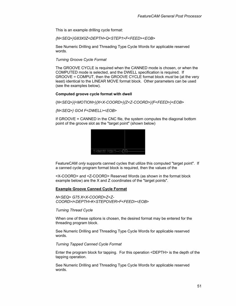
FeatureCAM General Post Processor
51
This is an example drilling cycle format:
{N<SEQ>}G83X0Z<DEPTH>Q<STEP1>F<FEED><EOB>
See Numeric Drilling and Threading Type Cycle Words for applicable reserved words.
Turning Groove Cycle Format
The GROOVE CYCLE is required when the CANNED mode is chosen, or when the COMPUTED mode is selected, and the DWELL specification is required. If GROOVE = COMPUT, then the GROOVE CYCLE format block must be (at the very least) identical to the LINEAR MOVE format block. Other parameters can be used (see the examples below).
Computed groove cycle format with dwell
{N<SEQ>}{<MOTION>}{X<X-COORD>}{Z<Z-COORD>}{F<FEED>}<EOB>
{N<SEQ>} GO4 F<DWELL><EOB>
If GROOVE = CANNED in the CNC file, the system computes the diagonal bottom point of the groove slot as the "target point" (shown below)
FeatureCAM only supports canned cycles that utilize this computed "target point". If a canned cycle program format block is required, then the values of the
<X-COORD> and <Z-COORD> Reserved Words (as shown in the format block example below) are the X and Z coordinates of the "target points".
Example Groove Canned Cycle Format
N<SEQ> G75 X<X-COORD>Z<Z-COORD>I<DEPTH>K<STEPOVER>F<FEED><EOB>
Turning Thread Cycle
When one of these options is chosen, the desired format may be entered for the threading program block.
See Numeric Drilling and Threading Type Cycle Words for applicable reserved words.
Turning Tapped Canned Cycle Format
Enter the program block for tapping. For this operation <DEPTH> is the depth of the tapping operation.
See Numeric Drilling and Threading Type Cycle Words for applicable reserved words.
FeatureCAM General Post Processor
52
Using FeatureTURN and XBUILD Roughing and Profiling Cycles
Post applies the offset and other cycle data parameters that are appropriate to the cycle. XBuild provides the <X-COORD> and <Z-COORD> Reserved Words to receive the path coordinate data. Additional Reserved Words: <ARC-X>, <ARC-Z>, <X-CEN>, <Z-CEN>, <RADIUS> and <S-RAD> are provided by XBuild to receive the circular interpolation modifiers that are needed for arc moves.
START/END PTS If start or endpoints have been defined in FeatureTURN, they become part of the path's definition. Post generates a rapid move from a start point to the first part of the machining operation, and a rapid move from the last move of the operation to the endpoint is also generated.
OTHER RESERVED WORDS Optional sequence numbering is defined in Post, and is placed at the beginning of any block that contains the Reserved Word, <SEQ>.
The end of block character (a control code that signals a completed line) is defined by the <EOB> Reserved Word (GENERAL INFO).
TURN/MILL Posts Turn/mill posts are a separate type that combines the features of milling and turning. On the General page set the Machine Type to Turn/Mill.
TURN/Mill Keywords In general, milling keywords are available in turn/mill mode when a milling feature is being processed. The same thing is true for turning keywords. The following are some exceptions: The milling keywords <CYCLE>, <PLANE>, <XY-PLANE>, <ZX-PLANE>, and <YZ-PLANE> are also available for turning features in turnmill mode. The turning keywords <SP-RANGE>, <F-UNITS>, and <RANGE-CH> are also available for milling features in turnmill mode. The milling keywords <X-VECTOR>, <Y-VECTOR>, <ROT2-ANSI>, <ROT2-MATH>, <ROT2-WIND>, and <USE-FIXTURE> are not available in turn/mill mode. The turning keywords <X-VECTOR> and <Z-VECTOR> are not available in turnmill mode.
Also, the turning keywords <Z-INDEX> and <X-INDEX> have been replaced by <Z-CHANGE> and <X-CHANGE>, respectively.
When XBUILD is in the turnmill mode, the Reserved Words dialog is color-coded to indicate the availability of the keywords.
TURNMILL logical variables The following logical variables on only available in turnmill posts.
FeatureCAM General Post Processor
53
<MILLING> True if current feature is a milling feature.
<ROTARYX> True if active tool is a rotary x tool. Applies to milling and drilling.
<TURNING> True if current feature is a turning feature.
Handling Turn/mill program formats Program Start Format and Tool Change Format
For milling moves, you must enable the C-axis and orient the C-axis in both of these formats. Here is an example for the Acramatic 850 TC:
<IF><MILLING><THEN> {N<SEQ> }M21<EOB> {N<SEQ> }S<SPEED> <SPINDLE> <EOB> {N<SEQ> }C<ROT1-WIND><EOB> <ENDIF>
Rapid Move Rapid moves should include the C axis move as shown below.
{N<SEQ> }{<MOTION> }{X<X-COORD> }{Z<Z-COORD> } <IF><MILLING><THEN> {C<ROT1-WIND>} <ENDIF>
Linear Move For machines in which FeatureCAM is doing the interpolation the formats must be conditional on whether it is a turning or milling move. In the milling case the C-axis rotation and the angular feedrate must be output. The following is an example from the Acramatic 850TC:
<IF><TURNING><THEN> {X<X-COORD> }{Z<Z-COORD> }F<FEED><EOB> <ENDIF> <IF><MILLING><THEN> {X<X-COORD> }{Z<Z-COORD> }{C<ROT1-WIND> }{F<ANG-FPM>}<EOB> <ENDIF>
For machines in which the controller performs the interpolation, make sure to set Polar interpolation done by machine tool in the General Information dialog box. This changes the toolpaths as they are output from FeatureCAM into the post. Here is an example for a Fanuc 16, 18 or 21.
<IF><TURNING><THEN> {X<X-COORD> }{Z<Z-COORD> }F<FEED><EOB> <ENDIF> <IF><MILLING><THEN> {X<X-COORD> }{C<Y-Coord>}{Z<Z-COORD> }{F<FEED>}<EOB> <ENDIF>