portable survival kit
TRANSCRIPT
US007565968B2
(12) Ulllted States Patent (10) Patent N0.: US 7,565,968 B2 Lindley (45) Date of Patent: Jul. 28, 2009
(54) PORTABLE SURVIVAL KIT 4,648,013 A 3/1987 Curiel 4,686,441 A 8/1987 Petterson
(76) Inventor: Michael B. Lindley, 7 Moet Ct., Rancho 4,740,431 A 4/19gg Little M1rage,CA(U$)92270 4,808,904 A 2/1989 Ricaudet a1.
* _ _ _ _ _ 5,039,928 A 8/1991 Nishi et a1.
( ) Not1ce: Subject' to any d1scla1mer, the term ofthis 5,082,505 A M992 Com et a1‘ 1’??? llssixgeltdegfé adlusted under 35 5,111,127 A * 5/1992 Johnson .................... .. 320/101
' ' ' ( ) y ays' 5,225,003 A 7/1993 Ming-Che et a1.
’ 5,379,596 A 1/1995 Grayson
(22) Filed: Mar. 12, 2007 5,387,858 A 2/1995 Bender et 31. 5,500,052 A 3/1996 Horiuchi et a1.
PI‘lOI‘ Publication Data 5,515,974 A 5/1996 Higson
US 2007/0221515 A1 Sep. 27, 2007 5,522,943 A 6/1996 Spencer et a1~ 5,605,769 A 2/1997 Toms
Related US. Application Data 5,644,207 A 7/1997 Lew et a1,
(60) Provisional application No. 60/767,228, ?led on Mar. 5,644,294 A 7/1997 Ness 13’ 2006 5,660,643 A 8/1997 Toggweiler et a1.
(51) Int. Cl. B65D 71/00 (2006.01) '
B65D 81/32 (2006.01) (Contmued) H01M 10/44 (2006.01) . . Primary ExamlneriAkm E Ullah
(52) U..S. Cl. ...... .... ...... ... ..... .. 206/223, 426/115, 320/101 Assistant ExamineriMBaye Diao (58) Field of Classi?cation Search ............... .. 363/108; (74) Attorney] Agent] or FirmiLemer’ David’ Littenberg’
429/92, 97, 100, 150, 163; 206/223; 426/115; Krumholz & Memlik, LLP 307/150; 323/299, 906; 320/101
See application ?le for complete search history. (57) ABSTRACT
(56) References Cited
U.S. PATENT DOCUMENTS A portable survival kit includes a housing de?ning an internal compartment. One or more rechargeable energy sources are
360,934 A 4/1887 Waite . . . 2,230,458 A 21941 Hummen 1ns1de the compartment. One or more electr1cal generators are 2,274,285 A * 2/1942 Walker ..................... .. 219/387 associated With the housing Each electrical generator is 2,765,133 A * 10/1956 Antonidis ................. .. 248/645 adapted to facilitate Charging Of at least one Ofthe recharge 3,094,439 A 6/1963 Mann et a1. able energy sources. One or more electrical elements are 3,376,164 A 4/ 1968 BachWanSky associated With the housing and each electrical element is 3,963,972 A 6/1976 T°dd_ adapted to receive electrical energy from at least one of the 4,122,396 A 10/1978 GTazler et 31' rechargeable energy sources. Also, a source of edible human
i $251M et a1‘ nourishment is stored inside the compartment. 4,376,250 A 3/1983 Baker, Jr. et 31. 4,421,943 A 12/1983 Withjack 24 Claims, 11 Drawing Sheets
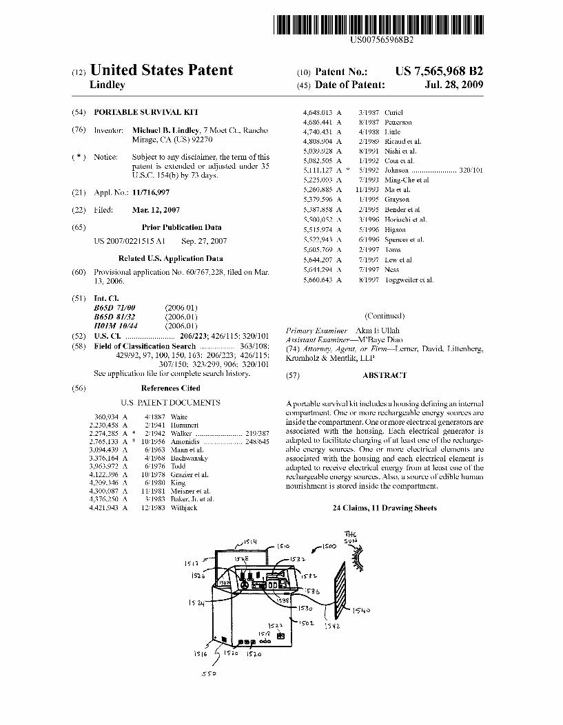
T146 EH 1510 1500 s£\
8 i H‘ 1 2 1:1 153 1 3
77. 152 e I we 1.
I50 0 7 U l? 36
1m w 53° 1514 9
i
1511 '7 ‘5°?’ 1542 . 1518
,5! 060
I 516 I? 19 1526
1550
US 7,565,968 B2 Page 2
US. PATENT DOCUMENTS 6,774,299 B2 8/2004 Ford 6,812,396 B2 11/2004 Makita 6131.
5,692,647 A 12/1997 Brodie 6,847,130 B1 1/2005 Belehradek 6131. 5,701,067 A 12/1997 Kaji er 91- 6,884,934 B2 4/2005 Tsuzuki et a1. 5713655 A 2/1998 Blackman 6,894,439 B2 5/2005 Stewart 6131. 5,714,869 A 2/1998 Tamechika eta1~ 6,914,340 B2 7/2005 Becker et a1. 5,925,942 A 7/1999 Theobald 6,917,188 B2 7/2005 Kemahan 5,969,501 A 10/1999 Glidden eta1~ 6,930,237 B2 8/2005 Mattiuzzo 6131. 5,977,659 A 11/1999 Takehara et a1. 6,930,403 B2 g/2005 Hartman et 31‘ 6,034,443 A 3/2000 Oliemuller et a1. 6,949,843 B2 9/2005 Dubovsky 6,041,242 A 3/2000 Coulthard 2002/0047627 A1 4/2002 Pickering 6,046,400 A 4/2000 Drummer 2002/0067143 A1 6/2002 Robinett 6131. 134251018 5 5/2000 Madura eta1~ 2002/0171391 A1 11/2002 Batts-Gowins 6,326,764 B1 * 12/2001 Viltudes ................... .. 320/101 2003/0160592 A1>1< 8/2003 Mumkami et a1‘ ________ u 320/116
6376764 B1 4/2002 L119 eta1~ 2003/0167105 A1 9/2003 Colborn 6,396,239 B1 5/2002 Benn eta1~ 2003/0214270 A1 11/2003 Shiue 6131. 6,404,620 B1 6/2002 Piccione 2004/0207330 A1 10/2004 Ruffell et a1. 6,448,489 B2 9/2002 Kimura 6161. 2004/0239287 A1 12/2004 Batts-Gowins 6,476,311 B1 11/2002 Lee etal. 2005/0062456 A1 3/2005 Stone 6131. 6,479,743 B2 11/2002 Vaz etal. 2005/0142929 A1 6/2005 Cottle 6,538,341 B1 3/2003 Lang etal, 2005/0157482 A1 7/2005 Hsu 6,593,521 B2 7/2003 Kobayashi et a1. 2005/0213272 A1 9/2005 Kobayashi 6,610,919 B2 8/2003 ohkubo et a1‘ 2005/0218657 A1 10/2005 Weesner et a1.
6,686,534 B2 2,2004 Chen 2005/0233189 A1 10/2005 shloya 6,689,507 B1 2,2004 Tsutsumiet a1‘ 2006/0238317 A1* 10/2006 Colledge .................. .. 340/431
6,737,573 B2 5/2004 Yeh et a1. * cited by examiner
US. Patent Jul. 28, 2009 Sheet 1 0f 11 US 7,565,968 B2
/\00
f/wgg “m . HS
O \"O
FIG. 1 A
US. Patent Jul. 28, 2009 Sheet 2 0f 11 US 7,565,968 B2
/EDO
,"lOb [6B0 .
. _ -
| | | | | | | I l | | v b n | I | | | | I‘ . .
. _ _ . . .. . . _ , _ . _ . _
,. n
7
.; _ . . - _ _ ' .
I .
_ I
_ '.
f I | | | I | | a I | | I I 4|. | n l | | l
l I l l I I I I l l I I l I I l I I Q . l I l I ll _
l L I I I l l I I l-I _
. - -
,
a . .
1 . l
6 )N 7
- I . I
A,» I
\l v - I
_ 1
4
_ I
1, _ '
I. . / Au
1|“?
| | l , l l l l l l | | | | | | | I ‘I
| | | I | > u | | L a | I | I | | | r I 1 I I l v 1 | 4..
( IZGJ
us
J
FIG. 1B
US. Patent Jul. 28, 2009 Sheet 4 0f 11 US 7,565,968 B2
83..
gm
7%
\ ééom
12M ,
US. Patent Jul. 28, 2009 Sheet 5 0f 11 US 7,565,968 B2
v .0;
om: 6A.? ,1: . NU‘ n“.
Q ~ g (‘5E4 .
A2,} , sgmmvn? r2», ., /
Aw; .
582.
\O .W p A; \<
6.7 a"? , (- BEE-U 5920
l w J W _ Q22 55A . ...~ . 37K ~.,_% 1%
r1 .Bwi Ema
cw\ . 6 6
w w? ,5“ E E 1.5,
_
z§\\
U.S. Patent Jul. 28, 2009 Sheet 6 6f 11 US 7,565,968 B2
m .65
"@Qm.
ma, .6, o ,.. , < C
, Tom
Wain . EQEBQQM
, New
. .mom , , , % ._6§_§om Om» . “$664 5
.630 we 883w 65m
1
US. Patent Jul. 28, 2009 Sheet 8 0f 11 US 7,565,968 B2
ZN
3.2m , m
., _ 3 1M5 ,N.
, \ .J , . _. l \ \.. .. ,
3: gm 1% Q32“ / A3?‘ 33 wow 3W8“ 3.» Q.» _ i, , v ,
J .Qnmv 3.1.1 N. L ?air),
w “NE @E .,,.©..% 0
. - \nsa
3 Tall (111» NM \e ah; .. ._ >3» /
W 9 .\~.\ _ 4 gm,‘
%1 ,1 3A L, Q .2,» N 5,,»
m,» n39»
;. ho. K63? .? . ‘I!
I.“ . , .
t . am 3.» . 2
i . 2p
US. Patent Jul. 28, 2009 Sheet 9 0f 11 US 7,565,968 B2
US. Patent Jul. 28, 2009 Sheet 10 0f 11 US 7,565,968 B2
US. Patent Jul. 28, 2009 Sheet 11 0f 11 US 7,565,968 B2
US 7,565,968 B2 1
PORTABLE SURVIVAL KIT
CROSS-REFERENCE TO RELATED
APPLICATION(S)
This application claims the bene?t of the ?ling date of Us. Provisional Patent Application No. 60/767,228, ?led Mar. 13, 2006, the disclosure of Which is hereby incorporated herein by reference.
FIELD OF THE INVENTION
This invention relates generally to a survival kit and, more particularly, to a portable survival kit that is particularly Well suited to facilitate long-term survival under a variety of adverse circumstances.
BACKGROUND OF THE INVENTION
Unfortunately, a variety of emergency situations occur and often people ?nd themselves unprepared to deal With such emergency situations. Those situations can leave people stranded, sometimes for extended periods of time, With little to no access to food, Water, communication equipment and information about rescue efforts, etc. that might be underWay.
Those emergency situations can arise, for example, as a result of severe ?ooding, earthquakes and terrorist activities. When such situations do arise, they can be very threatening and often the people that are subjected to such situations are ill-prepared to deal With the consequences.
SUMMARY OF THE INVENTION
In one aspect, a portable survival kit includes a housing de?ning an internal compartment. One or more rechargeable energy sources are inside the compartment. One or more electrical generators are associated With the housing. Each electrical generator is adapted to facilitate charging of at least one of the rechargeable energy sources. One or more electri cal elements are associated With the housing and each elec trical element is adapted to receive electrical energy from at least one of the rechargeable energy sources.Also, a source of edible human nourishment is stored inside the compartment.
In some embodiments, the housing is substantially Water resistant and/ or substantially Water proof.
In a typical embodiment, the one or more electrical gen erators include a dynamo With a hand-operable mechanical actuator to facilitate inputting mechanical energy to the dynamo. The mechanical actuator typically is a cranking mechanism.
According to some embodiments, the one or more electri cal generators include a plurality of solar cells, Which, for example, can be formed on a ?exible substrate that is foldable for storage inside the compartment. In some embodiments, the one or more electrical generators include a Wind-operable generator. Typically, the Wind-operable generator is storable Within the compartment.
Certain embodiments of the survival kit include a poWer cord adapted for connection to a household poWer outlet. The poWer cord is adapted, When connected, to deliver charging current from the household poWer outlet to at least one of the rechargeable energy sources.
In some embodiments, a light is coupled to the housing and is adapted to illuminate upon failure of household poWer via the poWer cord. Typically, that light is exposed at an external surface of the housing.
20
25
30
35
40
45
50
55
60
65
2 The one or more electrical elements can include, for
example, one or more cellular telephone charging ports, Wire less communication devices, televisions, rechargeable ?ash lights, fans, a DC. outlets, A.C outlets, lights, etc, or any combination thereof. Typically, those elements are either inside or somehoW associated With the housing of the kit.
According to certain embodiments, the one or more rechargeable energy sources include a ?rst battery (e. g., a 3.6 volt battery pack) adapted to supply electrical energy to a ?rst set of the electrical elements (e. g., a Wireless communication device and a light) and a secondbattery (e.g., a 12 volt battery) adapted to supply electrical energy to a second set of the electrical elements (e.g., DC. and AC. electrical outlets). Typically, the ?rst set of electrical elements includes electri cal elements that are more critical to survival and long-term Well-being of the person using the kit than the second set of electrical elements. The source of edible human nourishment typically
includes a food source and a Water source. The amount of
food and Water in the source of edible human nourishment is typically adapted to provide a human With nourishment for a speci?c number of person-days (e.g., tWo person-days or six person-days or tWelve person days). In some embodiments, the portable survival kit also includes medical and survival supplies inside the housing.
Certain embodiments of the portable survival kit include an instrument platform inside the housing. The instrument panel is adapted to facilitate a user’ s interaction With one or more of the electrical elements. The instrument platform is typically coupled to the housing by a hinged connection so that moving the instrument platform about the hinge uncovers a storage compartment for the source of edible human nourishment beneath the instrument platform.
In some embodiments, the housing includes a body portion and a cover portion coupled to the body portion. The cover portion typically can be opened to provide access into the compartment. Moreover, the body portion and the cover are adapted to mate With each other in a manner that seals the compartment.
Certain embodiments of the portable survival kit include Wheels coupled to the housing and a telescoping handle coupled to the housing.
In another aspect, a portable survival kit includes a sub stantially Water-resistant housing that de?nes an internal compartment. First and second rechargeable energy sources are inside the compartment. A dynamo is associated With the housing and has a hand-operable mechanical actuator to facilitate inputting mechanical energy to the dynamo. The dynamo is adapted to facilitate charging of the ?rst recharge able energy source. Solar cells are formed on a ?exible sub strate that is foldable for storage inside the compartment. The solar cells are adapted to facilitate charging of the second rechargeable energy source. A ?rst set of electrical elements is associated With the housing and is adapted to receive elec trical energy from at least the ?rst rechargeable energy source. A second set of electrical elements is associated With the housing and is adapted to receive electrical energy from at least the second rechargeable energy source. A source of edible nourishment is inside the compartment and is adapted to provide a human With nourishment for a speci?c number of person-days.
According to some embodiments, the ?rst set of electrical elements includes a Wireless communication device and a light and the second set of electrical elements includes DC. and AC. electrical outlets. Additionally, some embodiments include a poWer cord that is adapted for connection to a household poWer outlet and adapted, When connected to a
US 7,565,968 B2 3
household power outlet, to deliver charging current from the household poWer outlet to the second rechargeable energy source. Moreover, some embodiments include a light coupled to the housing, Where the light is adapted to illuminate upon failure of household poWer via the poWer cord.
In some embodiments, one or more of the folloWing advan tages are present. A portable survival kit is provided that includes a source of
emergency food and Water, key telecommunication and infor mation accessing equipment, an electrical energy source for that equipment and a means for maintaining or replenishing the charge on those electrical energy sources. Since the charge on the energy sources can be replenished, access to the equipment (e.g., phones, radios, Walkie-talkies, etc.) is main tained for an extended period of timeiindeed, far longer than Would otherWise be available simply With battery poWered equipment. Moreover, since the food and Water supply are included in the kit, the person using the kit Will have energy and be able to live for far longer than they otherWise Would have been able to live. Including all of these features in a compact, Waterproof housing makes them readily available and likely to survive otherWise potentially damaging events, such as earthquakes, ?oods, etc. Providing means to maintain the charge on the energy sources from a household outlet ensures that the kits Will be ready for use Whenever they are needed. Also, having a poWer failure light exposed on an outer surface of the housing makes it easier to ?nd the kit in the event of a blackout, Which Would normally accompany a serious ?ood or an earthquake.
Other features and advantages Will be apparent from the folloWing descriptions, claims and the draWings.
BRIEF DESCRIPTION OF THE DRAWINGS
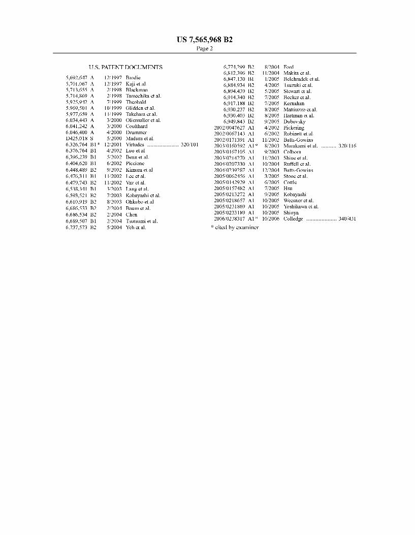
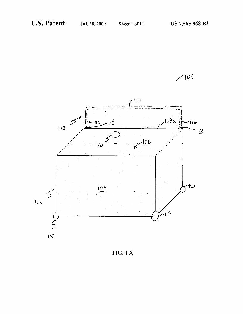
FIG. 1A is a perspective vieW of a portable survival kit. FIG. 1B is a cutaWay perspective vieW of the survival kit of
FIG. 1A With its cover in an open position. FIG. 2 is a cross-sectional vieW of the battery/electronics
compartment of the survival kit taken across lines 2-2 in FIG. 1B.
FIG. 3 is a cross-sectional vieW of the survival kit 100 taken across lines 3-3 in FIG. 1B.
FIG. 4 is a plan vieW of the instrument panel 124 of the survival kit 100 in FIG. 1B.
FIG. 5 is a schematic diagram of electrical circuitry asso ciated With the survival kit of FIGS. 1A, 1B and 2-4.
FIG. 6 is a schematic diagram shoWing the electrical con nections betWeen the various electrical components associ ated With the survival kit of FIGS. 1A, 1B and 2-5.
FIG. 7 is a cutaWay perspective vieW of an alternative portable survival kit.
FIG. 8 is a plan vieW of the survival kit of FIG. 7 taken across lines 8-8.
FIG. 9 is a cross-sectional vieW of the survival kit of FIG. 7 taken across lines 9-9.
FIG. 10 is a cross-sectional side vieW of the survival kit 700 of FIG. 7 taken across lines 10-10.
FIG. 11 is a cutaWay perspective vieW of yet another por table survival kit.
FIG. 12 is a plan vieW of the portable survival kit of FIG. 11 taken along lines 12-12.
FIG. 13 is a plan vieW of the portable survival kit of FIG. 11 taken along lines 13-13.
FIG. 14 is a vieW of the inside of the cover of the portable survival kit of FIG. 11.
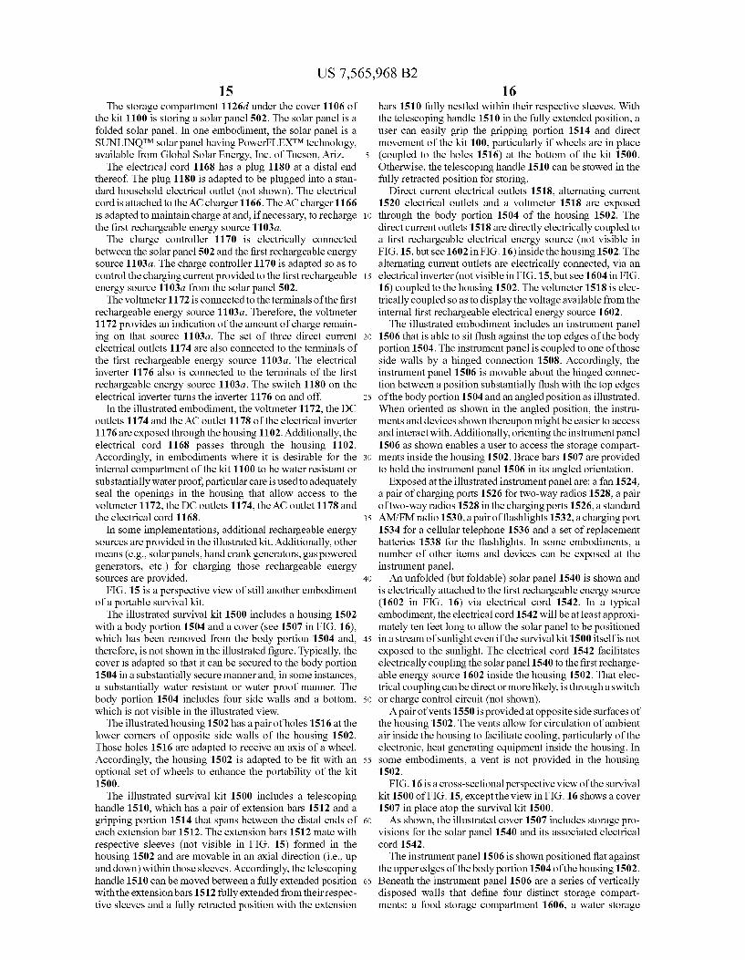
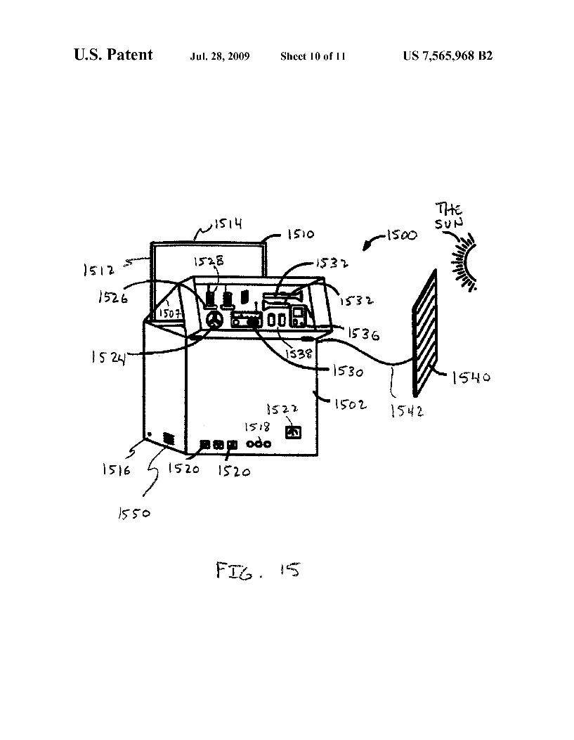
FIG. 15 is a perspective vieW of still another embodiment of a portable survival kit.
20
25
30
35
40
45
50
55
60
65
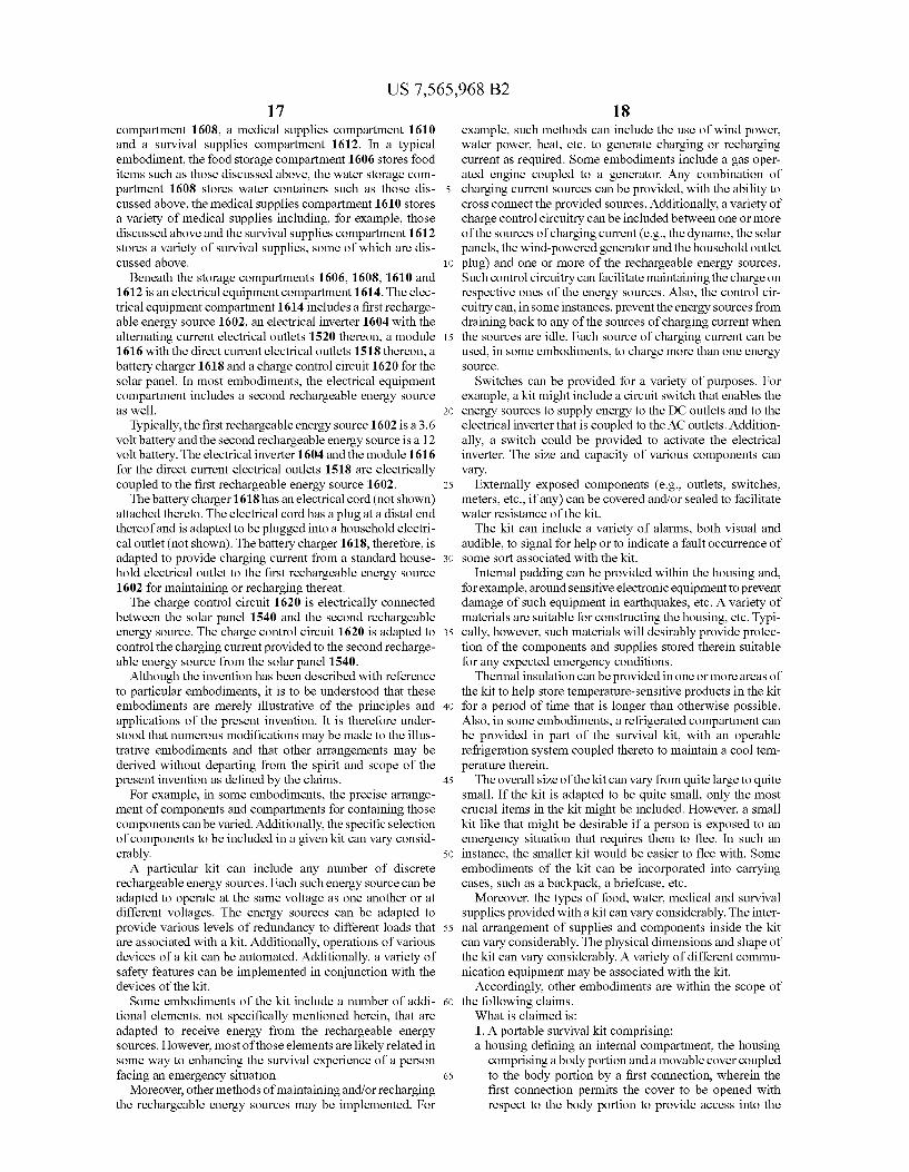
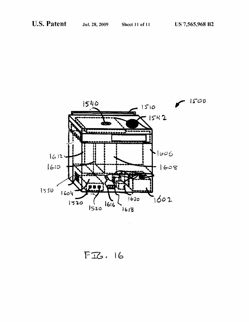
4 FIG. 16 is a perspective cutaWay vieW of the portable
survival kit of FIG. 15. Like reference numerals refer to like elements.
DETAILED DESCRIPTION OF THE DRAWINGS
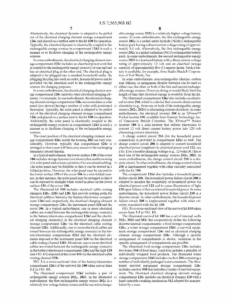
FIG. 1A is a perspective vieW of a portable survival kit 100 that, in general, stores a variety of items that are particularly suited to help a person to survive for an extended period of time in emergency situations, such as extreme ?oods, earth quakes, etc. The illustrated kit 100 includes a housing 102 With a body
portion 104 and a cover 106. The body portion 104 and the cover 106 typically are made of a substantially rigid material, such as molded plastic. In the illustrated embodiment, body portion 104 and the cover 106 are secured together via a ?rst hinged connection 108a so that the cover 106 can be sWung open to expose a compartment inside the housing 102. The cover 106 mates With the body portion 104 in a manner such that the internal compartment is sealed in at least a substan tially Water-resistant manner. HoWever, more preferably, the internal compartment is sealed in a substantially Water-tight manner.
The illustrated kit 100 includes Wheels 110 that facilitate its portability. More particularly, the Wheels 110 enable a user to roll the kit around. The illustrated embodiment has four Wheels 110. HoWever, it should be understood that other embodiments could include more or less Wheels 110 than shoWn. Indeed, in certain embodiments, particularly if the Weight of the kit 100 is loW, the Wheels 110 may be omitted altogether. The illustrated kit 100 also includes a telescoping handle
112. The telescoping handle 112 has a pair of extension bars 116 and a gripping portion 114 that spans betWeen the distal ends of each extension bar 116. The extension bars 116 mates With respective sleeves 118 formed in the housing 102 and are movable in an axial direction Within those sleeves 118. Accordingly, the telescoping handle 112 can be moved betWeen a fully extended position With the extension bars 1 16 fully extended from their respective sleeves 118 and a fully retracted position With the extension bars 116 fully nestled Within their respective sleeves 118. With the telescoping handle 112 in the fully extended position, a user can easily grip the gripping portion 114 and direct movement of the kit 100. OtherWise, the telescoping handle 112 can be stoWed in the fully retracted position for storing. As discussed in further detail beloW, the illustrated kit 100
includes one or more rechargeable energy sources (not visible in FIG. 1A), such as batteries. An electrical poWer cord 122 is provided that can be plugged into an ordinary household electrical outlet. When plugged into such an outlet, the elec trical poWer cord 122 delivers energy suf?cient to maintain a charge on at least one of the rechargeable energy sources. The energy provided by the electrical poWer cord 122 may be used for other purposes as Well. A light 120 is exposed at an outer surface of the housing
102. In some embodiments, the light 120 is adapted to auto matically illuminate upon failure of the electrical poWer source being provided via the electrical poWer cord 122. In such instances, illumination from the light 120 Would help a user locate the kit 100, for example, in the event of a poWer failure. In some instances, the light 120 is hand-operable and can be turned on or off by simply manipulating a sWitch located, for example, inside the housing 102.
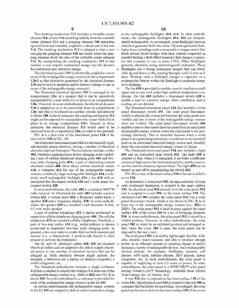
FIG. 1B is a cutaWay perspective vieW of the survival kit 100 of FIG. 1A With its cover 106 in an open position relative to the body portion 104.
US 7,565,968 B2 5
An instrument panel 124 is coupled at a proximal edge thereof to an upper edge of the body portion 104 via a second hinged connection 10819. The second hinged connection 1081) enables the instrument panel 124 to be moved so that its distal end can sWing open, thereby uncovering a set of internal compartments beloW the instrument panel 124. In a typical embodiment, the second hinged connection 108!) is adapted to alloW the instrument panel 124 to be rotated at least ninety degrees up from a position that is substantially ?at against the upper edges of the body portion 104.
The instrument panel 124 typically is a rigid material such as a molded plastic and includes a number of electrical devices (e.g., a radio, electrical outlets, etc.) and, perhaps some non-electrical devices exposed at an upper surface thereof. Accordingly, a user is able to gain access to those devices by simply opening the cover 106.
In order to facilitate a user’s interaction With the device(s) exposed at the upper surface of the instrument panel 124, the instrument panel 124 can be angled upWard relative to the plane de?ned by the upper edges of the body portion 104 (as is shoWn). ToWard that end, supports 125 are provided at opposite ends of the instrument panel 124, near a distal edge thereof. The supports 125 hang approximately doWnWard from the instrument panel 124 and are adapted to engage a corresponding engagement feature (not shoWn in detail) near the upper edges of the body portion 104. With the supports 125 engaged in the corresponding engagement features, the instrument panel 124 can be maintained at an angled orien tation.
The illustrated housing 102 has a set of internal Walls that cooperatively de?ne ?ve discrete internal compartments: a food storage compartment 126a, a Water storage compart ment 126b, a survival equipment storage compartment 1260, a battery/ electronics compartment 126d and an electrical charging element storage compartment 126e. Although a spe ci?c arrangement of compartments is shoWn, variations in the speci?c arrangement of compartments are possible. For example, in some embodiments, the housing 102 contains a greater number or a lesser number of compartments than are illustrated. Indeed, in one embodiment, the internal Walls are excluded entirely and the housing 102, therefore, includes only one internal compartment.
In a typical embodiment, the food storage compartment 126a includes a number of discretely packaged food items. Desirably, those food items have high nutritional value and a long shelf life. It is also desirable that the food items be substantially non-thirst provoking and include no ingredients that cause commonly knoWn allergic reactions. Furthermore, it is desirable that the food items require no additional prepa ration prior to eating. Additionally, it is desirable that the packaging of the food items provide for e?icient storing Within the food storage compartment 12611.
In one example, each food item is an emergency food ration bar, such as The ER BarTM, Which is available from Vita-Life IndustriesTM, Inc. Of Moorpark, Calif. ER barsTM generally have high nutritional value, a shelf life of approximately ?ve years, are substantially non-thirst provoking, have no ingre dients that might cause dangerous allergic reactions and are ready to eat Without additional preparation.
The Water storage compartment 126!) typically includes one or more Water containers. The Water desirably has a long shelf life, is puri?ed and substantially bacteria free. Addition ally, the Water preferably is packaged in a manner that it can be e?iciently stored Within the Water storage compartment 12619. In one example, the Water containers are Aqua Blox® Water containers, Which are available fromAqua Blox®, LLC of West Palm Beach, Fla. An Aqua Blox® Water container
20
25
30
35
40
45
50
55
60
65
6 contains puri?ed and substantially bacteria free drinking Water With a United States Coast Guard approved ?ve year shelf life. The Water containers are aseptically packaged. Aqua Blox® Water packages are available in 8.45 ?uid ounce (250 ml) containers. Aqua Blox® Water containers can With stand temperatures ranging from —22 to 150 degrees Fahren heit. Furthermore, Aqua Blox® Water containers are commer cially sterile and, therefore, can be used as a Wound cleanser or an eye Wash. To use an Aqua Blox® Water container in that manner, a user Would simply insert a straW into the container and squeeZe the container With su?icient pressure to eject a sterile Water stream through the straW.
In a typical embodiment, the food storage compartment 126a and the Water storage compartment 126!) are respec tively siZed so as to accommodate an amount of food and/or Water (i.e., the source of human nutrition) designed to last for a speci?ed number of person-days (e.g., approximately six person-days). If, for example, the kit 100 Were designed to provide a three-day source of nutrition for tWo people (i.e., six person-days), then the food storage compartment 126a might contain tWo packs of ER barsTM, each pack containing six 400 calorie bars and the Water storage compartment 1261) might contain tWelve 250 ml (8.45 02.) Aqua Blox® containers of Water. If tWo people used such a kit 100, then each person Would be able to eat tWo ER barsTM and drink tWo Aqua Blox® Water containers each day, for three days. The dimensions of each ER barTM are approximately 6.25
inches by 4.5 inches by 1.375 inches. The dimensions of each Aqua Blox® container are approximately 4.25 inches by 2.625 inches by 1.75 inches. In the example under consider ation, the food storage compartment 126a Would be large enough to accommodate at least tWelve such ER barsTM and the Water storage compartment 126!) Would be large enough to accommodate at least tWelve suchAqua Blox® containers. In order to maximiZe space usage, those compartments 126a, 1261) Would not be siZed any larger than that. The survival equipment storage compartment 1260 typi
cally includes a collection of medical and/or other survival items. In some embodiments, those items include ?rst aid equipment, such as Band-Aids, aspirin, medicinal lotions, bandages, etc., blankets, matches, a compass, toiletries, such as a toothbrush, toothpaste, deodorant, etc. The battery/electronics compartment 126d is located in the
loWerpor‘tion of the internal compartment of the housing 102. That compartment 126d typically includes one or more rechargeable energy sources (e.g., batteries) as Well as other electronic/electrical equipment (e.g., battery charging cir cuits, etc.) discussed herein. The one or more rechargeable energy sources are adapted to provide electrical energy, for example, to the electrical devices that are exposed at the instrument panel 124. Typically, locating the battery/elec tronics compartment 126d in the loWer portion of the housing 102 facilitates stability of the kit 100, because the heaviest items (e. g., the batteries) of the kit 100 are at the loWest part of the kit 100. Such an arrangement provides for a relatively loW center of gravity for the kit 100 and, therefore, enhances the relative stability of the kit 100. The electrical charging element storage compartment 126e
typically includes at least one element that is adapted to facilitate charging the one or more rechargeable energy sources (not shoWn in FIG. 1B) in the battery/electronics compartment 126d. In some embodiments, the electrical charging element is an electrical dynamo (not shoWn) With a hand operable cranking mechanism. In some embodiments, the electrical dynamo is secured in place inside the compart ment 126e With its hand operable crank mechanism facing upWard to alloW a user to manipulate the crank mechanism.
US 7,565,968 B2 7
Alternatively, the electrical dynamo is adapted to be pulled out of the electrical charging element storage compartment 126e and placed on a surface next to the kit 100 for operation. Typically, the electrical dynamo is electrically coupled to the rechargeable energy sources in compartment 126d in such a manner as to facilitate charging of the rechargeable energy sources.
In some embodiments, the electrical charging element stor age compartment 126e includes an electrical poWer cord that is coupled to the rechargeable energy source(s) at one end and has an electrical plug at the other end. The electrical plug is adapted to be plugged into a standard household outlet. By plugging the plug into such an outlet, household poWer can be provided via the electrical cord to the rechargeable energy sources for charging purposes.
In some embodiments, the electrical charging element stor age compartment 126e includes other electrical charging ele ments. For example, in one embodiment, the electrical charg ing element storage compartment 126e accommodates a solar panel (not shoWn) having a number of solar cells positioned thereupon. Typically, the solar panel is adapted to be pulled out of the electrical charging element storage compartment 126e and placed on a surface next to the kit 100 for operation. Additionally, the solar panel is electrically coupled to the rechargeable energy sources in compartment 126d in such a manner as to facilitate charging of the rechargeable energy sources.
The exact position of the electrical charging element stor age compartment 126e inside the housing 102 can vary con siderably. HoWever, typically that compartment 126e is arranged so that a user Will have easy access to the recharging
element(s) stored therein. In a typical embodiment, the loWer surface 130 of the cover
106 includes storage features (not shoWn) that enable stoWing of a solar panel and at least a portion of its associated cabling. The solar panel may be foldable so that it can be stoWed in a folded position. HoWever, the solar panel may be secured to the loWer surface 130 of the cover 106 in a non-folded man ner. In that instance, the solar panel may be arranged so that it can be exposed to sunlight While stored in place on the loWer surface 130 of the cover 106. The illustrated kit 100 includes electrical cable routing
channels 128a, 1281) and 1280 that provide routing paths for electrical cable(s) betWeen the battery/electronics compart ment 126d and, respectively, the electrical charging element storage compartment 126e, the instrument panel 124 and the cover 106. In a typical embodiment, one or more electrical cables are routed betWeen the rechargeable energy source(s) in the battery/electronics compartment 126d and the electri cal charging element(s) in the electrical charging element storage compartment 126e via the electrical cable routing channel 128a. Additionally, one or more electrical cables are
routed betWeen the rechargeable energy source(s) in the bat tery/ electronics compartment 126d and the electrical ele ments exposed at the instrument panel 124 via the electrical cable routing channel 1281). Moreover, one or more electrical cables are routed betWeen the rechargeable energy source(s) in the battery/ electronics compartment 126d and the light 120 (see FIG. 1A) exposed at the cover 106 via the electrical cable routing channel 1280.
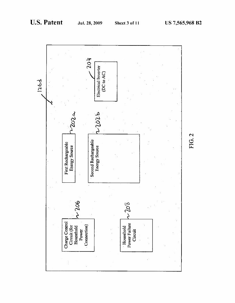
FIG. 2 is a cross-sectional vieW of the battery/electronics compartment 126d of the survival kit 100 taken across lines 2-2 in FIG. 1B.
The illustrated compartment 126d includes a pair of rechargeable energy sources 202a, 2021). In the illustrated embodiment, the ?rst rechargeable energy source 20211 is a relatively loW voltage battery source and the second recharge
20
25
30
35
40
45
50
55
60
65
8 able energy source 2021) is a relatively higher voltage battery source. In some embodiments, the ?rst rechargeable energy source 20211 is a nickel metal hydride (NiMH) rechargeable battery pack having a direct current voltage rating of approxi mately 3.6 volt. Alternatively, the ?rst rechargeable energy source 20211 is a nickel cadmium (NiCd) rechargeable battery pack. In some embodiments, the second rechargeable energy source 2021) is a lead acid battery With a direct current voltage rating of approximately 12 volt and an electrical storage capacity of approximately ?ve (5) ampere-hours. Such a bat tery is available, for example, from Radio Shack® Corpora tion of Fort Worth, Tex.
In some embodiments, non-rechargeable alkaline, carbon Zinc lithium, or manganese dioxide batteries can be used as either one, the other, or both of the ?rst and second recharge able energy sources. HoWever, doing so Would likely limit the length of time that electrical energy is available from the kit. The illustrated compartment 126d also includes an electri
cal inverter 204, Which is a device that converts direct current electricity (e.g., from one or both of the rechargeable energy sources 202a, 2021)) to alternating current electricity. In some embodiments, the electrical inverter 204 is an XPoWerTM Pocket Inverter 100, available from Xantrex Technology, Inc. of Vancouver, British Columbia. The XPoWerTM Pocket Inverter 100 is a mini-inverter that utiliZes electronics to convert 12 volt direct current battery poWer into 120 volt alternating current electricity. A charge control circuit 206 (for the household poWer
connection) is provided in compartment 126d as Well. The charge control circuit 206 is adapted to convert household electrical poWer (supplied via electrical poWer cord 122, see FIG. 1) to a useable charging voltage (e.g., 12 volts DC) for at least one of the rechargeable energy sources 202a, 2021). In some embodiments, the charge control circuit 206 is a dis crete circuit. In other embodiments, the charge control circuit 206 is implemented together With other circuitry associated With the kit 100.
The compartment 126d also includes a household poWer failure circuit 208. The household poWer failure circuit 208 is adapted to monitor the availability of household poWer via electrical poWer cord 122 and to cause illumination of light 120 upon failure of that monitored household poWer. In some embodiments, the household poWer failure circuit 208 is a discrete circuit. In other embodiments, the household poWer failure circuit 208 is implemented together With other cir cuitry associated With the kit 100.
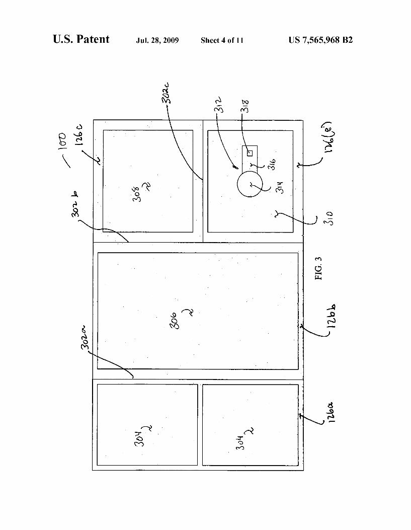
FIG. 3 is a cross-sectional vieW of the survival kit 100 taken across lines 3-3 in FIG. 1B. The illustrated survival kit 100 has a set of internal Walls
302a, 3021) and 3020 that cooperatively de?ne the folloWing discrete internal compartments: a food storage compartment 12611, a Water storage compartment 126b, a survival equip ment storage compartment 1260 and an electrical charging element storage compartment 126e. Although a speci?c arrangement of compartments is shoWn, variations in the speci?c arrangement of compartments are possible. The illustrated food storage compartment 126a includes
tWo boxes 304 of food items. Each box includes a plurality of individually Wrapped food products. The illustrated Water storage compartment 126!) includes one box 306 containing a number of individually packaged Water containers. The illus trated survival equipment storage compartment 1260 includes one box 308 that includes a variety of survival equip ment. The illustrated electrical charging element storage compartment 126e includes an electrical dynamo 310 With a hand-operable cranking mechanism 312 adapted for manipu lation by a user.
US 7,565,968 B2 9
The cranking mechanism 312 includes a rotatable center element 314, an arm 316 extending radially from the rotatable center element 314 and a gripping element 318 extending upward from and rotatably coupled to a distal end of the arm 316. The cranking mechanism 312 is adapted so that a user can grip the gripping element 318 and easily rotate the grip ping element about the axis of the rotatable center element 314. By manipulating the cranking mechanism 312 in that manner, a user imparts mechanical energy into the dynamo for conversion into electrical energy.
The electrical dynamo 310 is electrically coupled to one or more of the rechargeable energy sources (in the compartment 126d) so that electricity generated by the electrical dynamo 310 can be used to maintain and/or restore a charge at one or
more of the rechargeable energy source(s). The illustrated electrical dynamo 310 is arranged in its
compartment 126e in a manner that it can be operatively manipulated by a user while it is in place in its compartment 126e. However, in some embodiments, the electrical dynamo 310 is adapted so as to be removable from its compartment 126e and able to be placed on a surface outside and adjacent to the kit 100. In those instances, the cranking mechanism 312 might not be exposed for manipulation by a user while it is in place in its storage compartment 126e. Instead, in those instances, the electrical dynamo 310 would need to be removed from its compartment 126e in order to be operated.
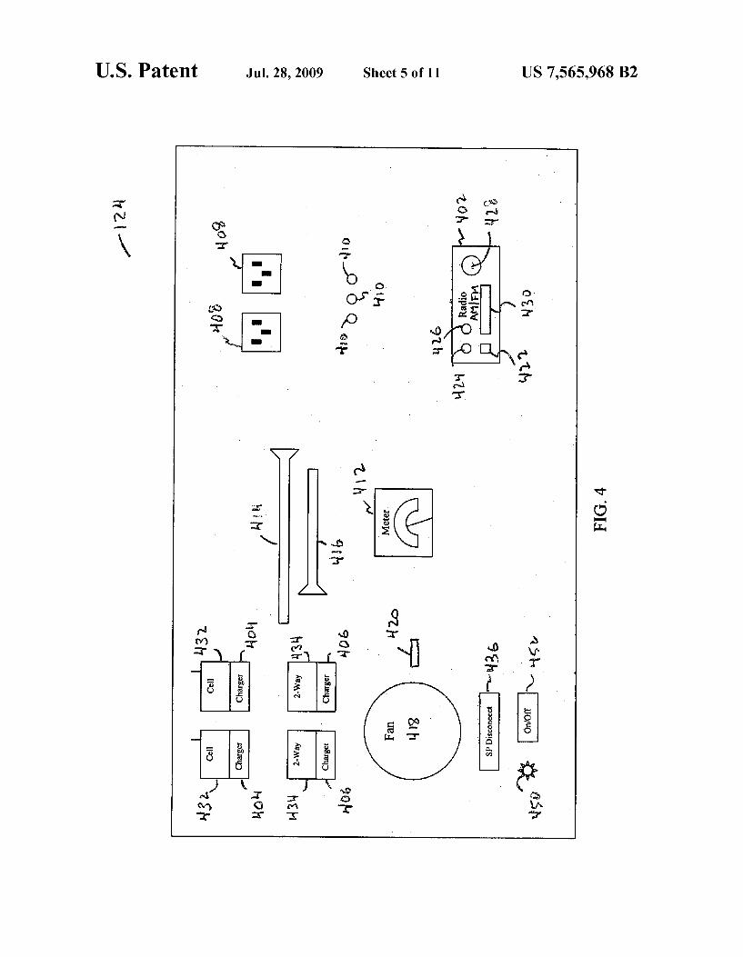
FIG. 4 is a plan view of the instrument panel 124 of the survival kit 100 in FIG. 1B. The illustrated instrument panel 124 is a substantially rigid,
substantially planar platform, having a number of electrical elements exposed thereupon. Those elements include: a radio 402, wireless communication device charging ports (includ ing a pair of cellular telephone charging ports 404 and two way radio charging ports 406), a pair of alternating current electrical outlets 408, three direct current electrical outlets 410, a voltmeter 412 for one of the rechargeable energy sources, a relatively large rechargeable ?ashlight 414, a rela tively small rechargeable ?ashlight 416, a fan 418 with an associated fan disconnect switch 420 and a solar panel dis connect switch 420.
In most embodiments, the radio 402 is a standard AM/FM radio receiver. As illustrated, the radio 402 includes a power switch 422, a volume knob 424, a frequency adjust knob, a speaker 428 and a frequency display 430. In some embodi ments, the speaker 428 is a standard 1 inch diameter, 8 ohm, 0.5 watt audio speaker. A pair of cellular telephones 432 is shown positioned in
respective cellular telephone charging ports 404. The cellular telephones 432 are standard cellular telephones. Similarly, a pair of two-way radios 434 (e.g., walkie-talkies) is shown positioned in respective two-way radio charging ports. In general, a two-way radio is a radio that can both transmit and receive (i.e., a transceiver). A push-to-talk button is often present to activate the transmitter.
The AC and DC electrical outlets 408, 410 are standard electrical outlets and are adapted to be able to supply electri cal power to any number of electrical devices that can be plugged in. Such electrical devices might include, for example, a television set, a laptop (or desktop computer), a small refrigerator, etc. The illustrated embodiment includes a single voltmeter
412 that is adapted to display the voltage of at least one of the rechargeable energy sources (e.g., 20211 or 2021) see FIG. 2) in the kit 100. In some embodiments, a voltmeter is provided for each of the rechargeable energy sources in the kit 100.
In certain embodiments, the rechargeable energy sources in the kit 100 are adapted to deliver and/or maintain a charge
20
25
30
35
40
45
50
55
60
65
10 at the rechargeable ?ashlights 414, 416. In other embodi ments, the rechargeable ?ashlights 414, 416 are indepen dently rechargeable. As an example, some ?ashlights have an electrical generator built into them. Dynamo-powered ?ash lights have a winding crank connected to a stepper motor that feeds several diode bridges with their outputs connected in parallel feeding a ?eld effect transistor that charges a capaci tor that connects to one or more LEDs. Other ?ashlights generate electricity using electromagnetic induction. Those ?ashlights use a strong permanent magnet that can freely slide up and down a tube, passing through a coil of wire as it does. Shaking such a ?ashlight charges a capacitor or a rechargeable battery within the ?ashlight to maintain charge or to recharge. The fan 418 is provided to enable a user to ventilate a small
space and to stay cool under high ambient temperature con ditions. The fan 418 includes a disconnect switch 420 to enable a user to conserve energy when ventilation and/or cooling are not desired. The illustrated instrument panel 124 also includes a solar
panel disconnect switch 436. The solar panel disconnect switch is electrically connected between the solar panel (not visible) and one or more of the rechargeable energy sources (also not visible). The solar panel disconnect switch 436 enables a user to disconnect the solarpanel from its associated rechargeable energy sources when the solar panel is not gen erating electricity. That is desirable because when a solar panel is not generating electricity, it could act as an electrical load on its associated electrical energy source and, possibly drain the associated electrical energy source of charge. The illustrated instrument panel 124 also includes a light
450 and an associated light switch 452. The light 450 is adapted so that, when it is energiZed, it provides a suf?cient amount of light across the instrument panel to enable a user to see the various elements exposed there. The light 450 can be turned on and off by manipulating the switch 452.
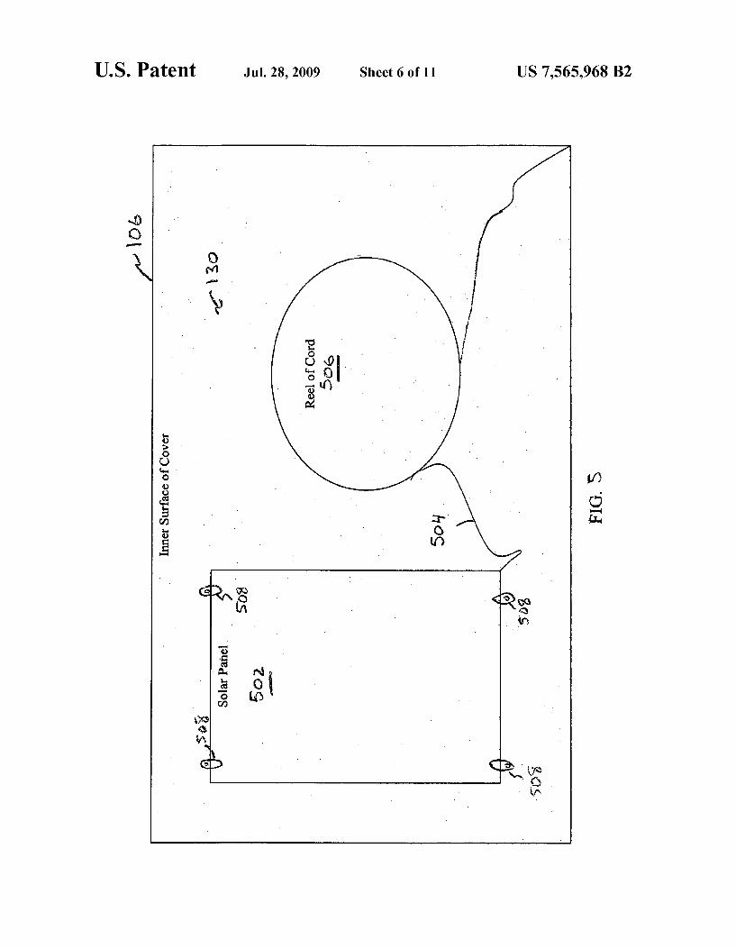
FIG. 5 is a view of the inner surface 130 of the survival kit’ s cover 106.
As illustrated, a solar panel 502, having a plurality of solar cells positioned thereupon, is coupled to the inner surface 130. An electrical cord 504 extends from the solar panel 502 and is coupled to a reel 506 on the inner surface 130. The electrical cord 504 couples the solar panel 502 (via a solar panel disconnect switch, which is not shown in FIG. 5) to at least one of the rechargeable energy sources (i.e., 20211 or 20219). The solar panel 502 is held in place against the inner surface 130 of the cover 106 by a set of fastening elements 508. In some embodiments, the solar panel 502 is stored in a folded position. However, in other embodiments, the solar panel 502 is stored in an unfolded position and arranged so that, when the cover 106 is open, the solar panel can be exposed to the sun’s rays. The solar panel 502 is desirably lightweight, ?exible, fold
able, durable, water resistant, and able to produce enough power in an e?icient manner to maintain charge at and/or recharge a variety of rechargeable devices. Such rechargeable devices include, for example, ?ashlights, lanterns, cell phones, GPS units, satellite phones, MP3 players, laptop computers, etc. In most embodiments, the solar panel is capable of supplying at least 6.5 watts of power. In some embodiments, the solar panel is a SUNLINQTM solar panel having PowerFLEXTM technology, available from Global Solar Energy, Inc. of Tucson, AriZ. A reel 506 also is exposed at the inner surface 130 of the
cover 106. The electrical cord 504 is coupled to the reel 506 in a manner that facilitates its unraveling. Accordingly, the solar panel can be removed from the inner surface 130 of the cover
US 7,565,968 B2 11
106 and positioned at a location remote from the survival kit 100. With the solarpanel 502 so positioned, the electrical cord 504 couples the solar panel 502 to the kit 100. More particu larly, the electrical cord 504 couples the solar panel to the rechargeable energy source associated With the solar panel.
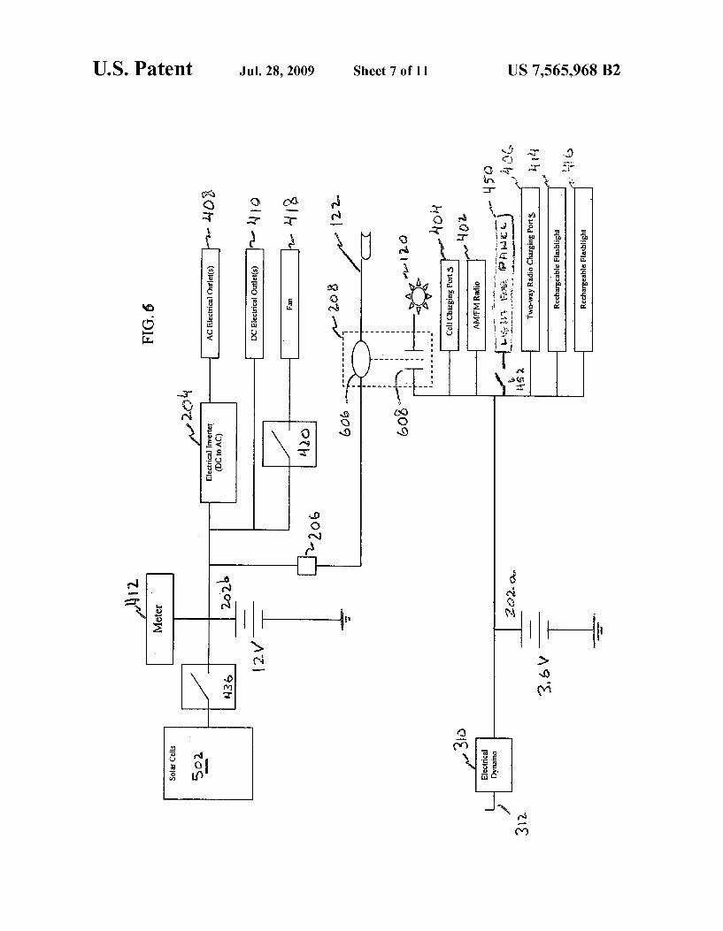
FIG. 6 is a schematic diagram shoWing the electrical con nections betWeen the various electrical components associ ated With the survival kit 100 of FIGS. 1A, 1B and 2-5.
The illustrated diagram shoWs the ?rst rechargeable energy source 20211 as a 3.6 volt battery. The ?rst rechargeable energy source 20211 is electrically connected, via a normally closed electrical contact, to the light 120 that is exposed at the outer surface of the kit’s cover 106 (see FIG. 1A). The nor mally closed electrical contact 602 is part of the household poWer failure circuit 208. The illustrated ?rst rechargeable energy source 20211 is connected directly to the cellular tele phone charging ports 404, the radio 402, the tWo-Way radio charging ports 406 and the rechargeable ?ashlights 414, 416, each of Which is exposed at the kit’ s instrument panel 124 (see FIG. 4).
The electrical dynamo 310 (Which has a hand-operable cranking mechanism 312) is directly electrically connected to the ?rst rechargeable energy source 202a and to the cellular telephone charging ports 404, the radio 402, the tWo-Way radio charging ports 406 and the rechargeable ?ashlights 414, 416. The electrical dynamo 310 also is electrically connected (via normally closed contact 502) to the light 120 exposed at the outer surface of the kit’s cover 106.
The illustrated diagram also shoWs the second recharge able energy source 202b as a 12 volt battery. The second rechargeable energy source 2021) is electrically connected, via a disconnect sWitch 420, to a fan 418 that is exposed at the kit’s instrument panel 124 (see FIG. 4). The illustrated second rechargeable energy source 2021) is connected directly to the DC electrical outlets 410 that are also exposed at the kit’s instrument panel 124 (see FIG. 4). Additionally, the second rechargeable energy source 2021) is electrically connected, via electrical inverter 204, to theAC electrical outlets 408 that also are exposed at the kit’ s instrument panel 124 (see FIG. 4).
The solar panel 502 (Which includes a plurality of solar cells) is electrically connected, via solar panel disconnect sWitch 436, to the second rechargeable energy source 202b, to the fan disconnect sWitch 420, to DC electrical outlets 410 and, via electrical inverter 204, to the AC electrical outlets 408. In some embodiments, a charge control circuit is coupled to the output of the solar panel 502. The solar panel discon nect sWitch 436 is provided because, When the solarpanel 502 is not generating electricity (e.g., When it is not exposed to a useful light source), the solar panel could undesirably act as an electrical load on the second rechargeable energy source 2021) and, thus, possibly drain the charge from the second rechargeable energy source 2021).
The voltmeter 412 is electrically connected to the second rechargeable energy source 2021) and is, therefore, adapted to measure and display the voltage available at the output node of the second rechargeable energy source 2021). A user, there fore, might use the voltage readings provided by that voltme ter 412 to determine When it might be desirable to activate and connect (by closing disconnect sWitch 436) the solar panel 502 to the second rechargeable energy source 2021).
The electrical poWer cord 122 With the electrical plug 604 at its distal end for plugging into a household electrical outlet is electrically connected, via charge control circuit 206 to the second rechargeable energy source 2021) and to each of the loads associated With the second rechargeable energy source 2021). If the electrical poWer cord 122 is electrically con nected to a household electrical outlet (not shoWn in FIG. 6),
20
25
30
35
40
50
55
60
65
12 then the cord 122 is adapted to deliver electrical charging energy to the second rechargeable energy source 2021) and to provide energy to the electrical loads that are coupled to the second rechargeable energy source 2021). The household poWer failure circuit 208 includes an elec
trical sensing element 606 and a normally closed contact 602. The electrical sensing element 606 senses Whether voltage is being provided at the electrical cord 122 from the household poWer source. If voltage is present at the electrical cord 122, then the normally closed contact 602 is held open. Upon failure of voltage at the electrical cord 122, the normally closed contact 602 closes. When the normally closed contact 602 closes, energy from the ?rst rechargeable energy source 20211 is provided (via the normally closed contact 602) to illuminate the light 120.
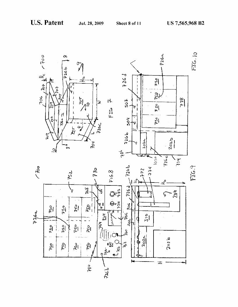
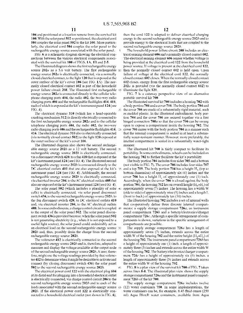
FIG. 7 is a cutaWay perspective vieW of an alternative portable survival kit 700. The illustrated survival kit 700 includes a housing 702 With
a body portion 704 and a cover 706. The body portion 704 and the cover 706 are made of a substantially rigid material, such as molded plastic. In the illustrated embodiment, body por tion 704 and the cover 706 are secured together via a ?rst hinged connection 708a so that the cover 706 can be sWung open to expose a compartment inside the housing 702. The cover 706 mates With the body portion 704 in a manner such that the internal compartment is sealed in at least a substan tially Water-resistant manner. HoWever, more preferably, the internal compartment is sealed in a substantially Water-tight manner.
The illustrated kit 700 is fairly compact to facilitate its portability. In some embodiments, Wheels can be included on the housing 702 to further facilitate the kit’s portability. The body portion 704 includes four sides 705 and a bottom
(not visible in FIG. 7). The cover 706 includes four sides 707 and a top 709. The body portion 704 has a height Hb (top to bottom dimension) of approximately six (6) inches and the cover 706 has a height Hc of approximately one (1) inch. Accordingly, When the cover 706 is closed against the body portion 704, the housing 702 has an overall height (Hb+Hc) of approximately seven (7) inches. The housing has a Width W (side to side) of approximately nine (9) inches and a length L (front to back) of approximately ten (10) inches. The illustrated housing 702 includes a set of internal Walls
that cooperatively de?ne three discrete internal compart ments: a supply storage compartment 726a, an instrument panel compartment 726!) and a battery/electronics/ charger compartment 7260. Although a speci?c arrangement of com partments is shoWn, variations in the speci?c arrangement of compartments are possible. The supply storage compartment 72611 has a length of
approximately seven (7) inches, extends across the entire Width W of the housing 702 and the entire height (Hb+Hc) of the housing 702. The instrument panel compartment 726!) has a height of approximately one (1) inch, a length of approxi mately three (3) inches and extends across the entire Width W of the housing 702. The battery/electronics/ charger compart ment 7260 has a height of approximately six (6) inches, a length of approximately three (3) inches and extends across the entire Width W of the housing 702.
FIG. 8 is a plan vieW ofthe survival kit 700 ofFIG. 7 taken across lines 8-8. The illustrated plan vieW shoWs the supply storage compartment 726a and the instrument panel compart ment 72619 of the kit 700. The supply storage compartment 726a includes twelve
(12) Water containers 750. In some implementations, the Water containers can be, for example, 8.45 ?uid ounce (250 ml) Aqua Blox® Water containers, available from Aqua
US 7,565,968 B2 13
Blox®, LLC of West Palm Beach, Fla. In some implementa tions, each Water container 750 is approximately 5.625 inches by 3.125 inches by 0.875 inches and contains enough Water for a half of a person-day. The illustrated supply storage compartment also includes food items (not visible in FIG. 8) stored underneath the illustrated Water containers 250. Other supplies (e.g., ?rst aid supplies, additional Water containers, etc.) can be stored in the illustrated supply storage compart ment 72611 in the space 752 next to the Water containers 750.
The illustrated instrument panel compartment 726!) includes an instrument panel 724 With a light bulb 754, a sWitch 756 for the light bulb 754. The instrument panel 724 also includes a radio 758 With an on/off knob 760, a tuning knob 762 and a speaker 764. The instrument panel 724 also has a voltmeter 766 for one of the kit’s rechargeable energy sources. An electrical inverter 204 is exposed at the instru ment panel 724 and includes an integral three-prong altemat ing current outlet 768 as Well as an integral Universal Serial Bus (U SB) charging port 770. A direct current outlet 772 and a sWitch 774 for the direct current outlet 772 also are exposed at the instrument panel 724.
Typically, the light bulb 754 is adapted to illuminate the instrument panel 724 so that a user can see What he or she is doing When attempting to use the devices exposed thereon. The illustrated electrical inverter 204 is an XPoWerTM Pocket Inverter 100, available from Xantrex Technology, Inc. of Van couver, British Columbia. The illustrated Universal Serial Bus (USB) charging port 770 is adapted to interface With personal digital assistants, etc. for charging purposes. A charging port 780 for a cellular telephone is exposed to
a side surface of the instrument panel 724. The illustrated charging port 780 is adapted to receive a charging cable that can be coupled to a cellular telephone (not shoWn).
FIG. 9 is a cross-sectional vieW of the survival kit 700 of FIG. 7 taken across lines 9-9. In the illustrated embodiment, the kit’s cover 706 is shoWn in a closed position. The illus trated vieW shoWs a storage space 726d (in the cover 706), the instrument panel compartment 726!) in the body portion 704 and the battery/electronics/charger compartment 7260 in the body portion 704.
The storage space 726d in the cover 706 includes a solar panel 502. In the illustrated embodiment, the solar panel 502 is a SUNLINQTM solar panel having PoWerFLEXTM technol ogy, available from Global Solar Energy, Inc. of Tucson, AriZ. The illustrated solar panel 502 is folded for storage. The approximate dimensions of the folded solar panel 502 are 0.5 inches high, nine (9) inches long and ?ve (5) inches Wide. The solar panel 502 can be unfolded to dimensions of approxi mately 0.03 inches high, nine (9) inches long and 29.5 inches Wide.
The illustrated battery/electronics/charger compartment 7260 includes ?rst and second rechargeable energy sources 202a and 202b, an electrical dynamo 310 With a hand crank mechanism (the hand crank is not visible in FIG. 9) and portions of the electrical inverter 204, the direct current outlet 772 and the sWitch 774 for the direct current outlet 772. An internal Wall 776 is behind the battery/electronics/charger compartment 7260 and separates that compartment 7260 from the supply storage compartment 726a behind the Wall 77 6.
FIG. 10 is a cross-sectional side vieW of the survival kit 700 of FIG. 7 taken across lines 10-10.
The illustrated survival kit 700 shoWs the supply storage compartment 72611, the instrument panel compartment 72 6b, the battery/electronics/charger compartment 7260 and the storage space 726d in the cover 706.
20
25
30
40
45
50
55
60
65
14 The supply storage compartment 726a shoWs Water con
tainers 750 and food items 778 stored beneath the Water containers 750. In the illustrated embodiment, the food items 778 include tWo packages of The ER BarTM nutrition bars, available from Vita-Life IndustriesTM, Inc. of Moorpark, Calif. Each package includes six bars. The dimensions of each package are approximately 6.25 inches by 4.5 inches by 1.375 inches. The illustrated vieW of the battery/electronics/ charger
compartment 7260 shows that the ?rst and second recharge able energy sources 202a and 20219 extend almost entirely to the rear Wall 776 in that compartment 7260. The illustrated vieW of the storage space 726d in the cover
706 shoWs the solar panel 502 and its electrical cord 504 stored therein. A latch 1050 is provided and spans across the interface
betWeen the body portion 704 of the housing and the cover 706. When the latch is in a latched position, the latch 1050 maintains a very tight seal betWeen the body portion 704 and the cover 706. A hinged connection 1052 also is provided at the interface betWeen the body portion 704 and the cover 706. The hinged connection 1 052 is adapted so that, When the latch is not engaged, the cover 706 can sWing about the hinged connection 1052 relative to the body portion 704.
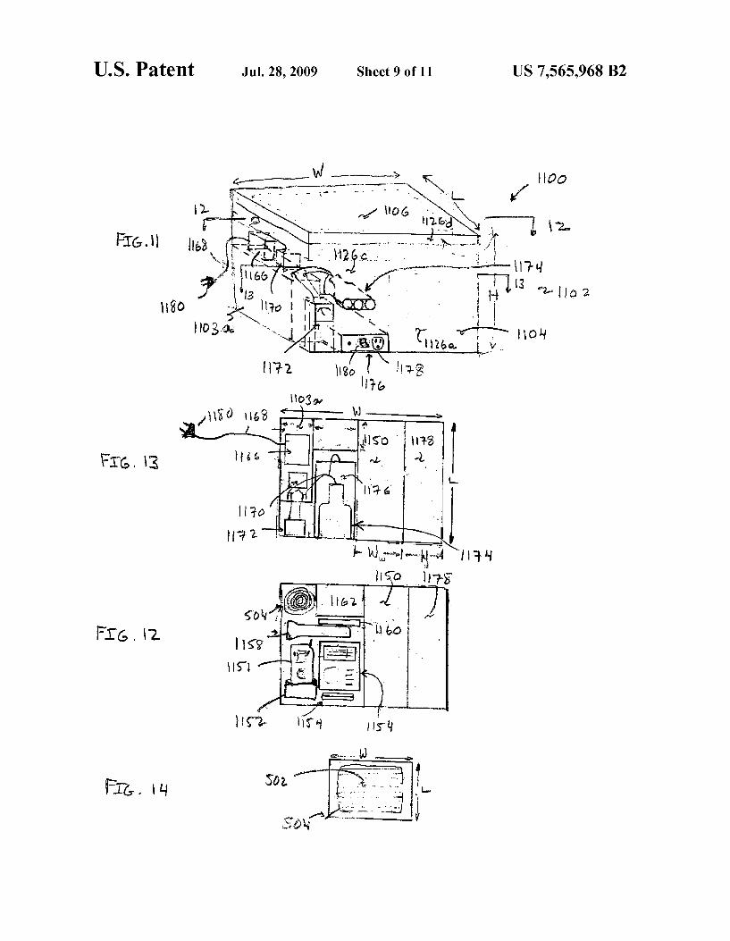
FIGS. 11-14 shoW various vieWs of yet another embodi ment of the portable survival kit 1100. The illustrated survival kit 1100 includes a housing 1102
With a body portion 1104 and a cover 1106. The body portion 1104 and the cover 1106 de?ne an internal compartment Within the housing 1102. The cover 1106 is removable from the body portion 1104, hoWever, is securable to the body portion 1104 in a manner that ensures that the internal com partment is at least Water resistant and, perhaps, Water proof.
The housing 1102 has an overall height H of approximately ten (10) inches, an overall length L of approximately eight (8) inches and an overall Width W of approximately tWelve (12) inches. The housing’s 1102 compact nature facilitates its portability.
The housing 1102 de?nes a number of compartments therein including a supply storage compartment 1126a, an instrument compartment 1 126b, a battery/ electronic s/ charger compartment 1126c and a cover storage compartment 1126d. Although a speci?c arrangement of compartments is shoWn, variations in the speci?c arrangement of compartments are possible. The supply storage compartment 1126a includes contain
ers 1178 of food and Water containers 1150. The Width WW of the Water storage space is approximately 3.5 inches and the Width Wf of the food storage space is approximately 2.5 inches. The food and Water storage spaces extend from the bottom of the housing 1102 to the cover 1106 and extend from the front of the housing 1102 to the back of the housing 1102.
The illustrated instrument compartment 1126b (see, e.g., FIG. 12) includes a tWo-Way radio 1151 in a charging port 1152, a multi-band radio 1154, a multi-purpose tool 1156, a large ?ashlight 1158, a small ?ashlight 1160, medical sup plies 1162 and a ten (10) foot long electrical cord 504 for the kit’s solar panel. The battery/electronics/ charger compartment 1126c
includes a ?rst rechargeable energy source 11031111 (i.e., in the illustrated embodiment a 12 volt battery), anAC charger 1166 With an electrical cord 1168 attached thereto, a charge con troller 1170 from the solar panel input, a voltmeter 1172, a set of three direct current electrical outlets 1174 and an electrical inverter 1176 With an integral three-prong alternating current electrical outlet 1178 and a sWitch 1180.