plenoptic imaging for 3dµptv investigations of micro-scale...
TRANSCRIPT
17th International Symposium on Applications of Laser Techniques to Fluid Mechanics Lisbon, Portugal, 07-10 July, 2014
- 1 -
Plenoptic Imaging for 3DµPTV Investigations of Micro-Scale Flows
David S. Nobes1,* Oly Chatterjee1, Alireza Setayeshgar1
1: Department of Mechanical Engineering, University of Alberta, Edmonton, Canada
* correspondent author: [email protected] Abstract It is difficult to measure all three components of velocity within a micro-scale flow field. Options for carrying out this type of management become more limited as the magnification needed to image the region-of-interest increases. Light field imaging using a plenoptic camera which allows the capture of complete light field within a single image and synthetic refocusing over the focal depth of the image has many potential advantages. Synthetic refocusing can be used to reconstruct the location of flow markers. These can then be tracked in conventional particle tracking methods. This paper discusses several of the main issues that need to be addressed in the development of this approach for application of the approach to micro-scale flow investigations. The results so far highlight that providing improved data to a PTV algorithm has many advantages. More work however is needed on determining the location of particles in 3D to improve the overall accuracy and reliability of this approach.
1. Introduction At the small size of a flow in a micro-channel (< 0.5 mm), mixing is dominated by diffusion and there
are present other forces not normally observed at the macro-scale. These include electro-static forces and near wall nano-scale forces that impact strongly on fluid transport (Masliyah and Bhattacharjee, 2006). These flow fields are often mathematically modeled as 2D, however, 3D flows are present and are now used to enhance mixing. Examples include the ‘caterpillar track’ motion observed in segmented flow (Günther et al., 2004) and the bifurcating-recombining flow present at the pore scale in porous media (Sen et al., 2012). These strongly three component velocity fields are challenging to experimentally investigate given that the physical size is so small and current techniques such as stereoPIV and tomoPIV require cameras at multiple view directions to determine the out-of-plane velocity component. Advances are needed in this area.
While the concept of plenoptic imaging has been available to researchers for some time (Gabor, 1948; Okoshi, 1976) it has only recently become practical (Levoy et al., 2012) with the advent of micro manufacturing and digital imaging technology. With conventional imaging, light within the focal plane is brought into focus by the imaging lens to form a sharp image. Light from other objects outside the focal plane generate a blurred response forming no image. With plenoptic imaging (Lynch et al. 2012), also known as light field imaging (Levoy et al., 2012), this light is redirected using a micro-lens array that is placed immediately in front of the imaging chip to different pixels within the sphere of influence of a single micro-lens. These individual pixels are at a different focal length from the single micro-lens which allows the light to be brought into focus. Using a suitable processing algorithm (Levoy et al., 2012) this extra information can be used to allow synthetic refocusing of the single captured image to different focal planes, or out-of-plane positions. In the context of imaging particle motion within a flow field, this approach would allow refocusing and reconstruction to form a three-dimensional data set of particle locations all from a single image. Standard approaches for tracking particle motion using particle tracking velocimetry (PTV) or particle image velocimetry (PIV) could then be applied to infer fluid motion.
The thin focal plane of a microscope objective can be used to localise particle positions in the out-of-plane direction (Nobes et al., 2010; Homeniuk, 2009). By sweeping a thin focal plane through a volume of interest and collecting image data at known locations a 3D volume of particle locations can be generated. This approach has been used to investigate the three-dimensional flow in a micro-channel (Homeniuk et al., 2008). The location of particles within the swept volume was determined by using a gradient approach to assess the variation of light in the out-of-plane direction (Homeniuk, 2006). This approach was used because the shape of particle volumes was affected by the generation of diffraction rings as particles moved out of the focal plane. A full 3D PTV tracking algorithm has been used to determine particle motion within the micro-channel (Homeniuk et al., 2008; Homeniuk, 2009). Two major limitations affect this approach for
17th International Symposium on Applications of Laser Techniques to Fluid Mechanics Lisbon, Portugal, 07-10 July, 2014
- 2 -
determining 3D particle velocities within a micro-channel. The thin focal plane is swept over the volume in a finite time within which particles can move. To reduce this effect, the focal plane needs to be moved rapidly through the volume. This however leads to significant vibration of the system as the objective goes through large acceleration changes and changes direction at the end of a volume sweep.
The work discussed in this paper outlines the current progress in developing a micro-imaging system based on a plenoptic camera for investigating three-dimensional motion in micro-scale flows using 3DµPTV. Individual components and their specifications will strongly impact the performance of the system and these will be discussed in detail. New work is required on investigating and developing techniques for the reconstruction step of the single plenoptic image into a 3D particle location data set. This step is affected by all other system components which need to be integrated together to form a complete system. Work presented here will highlight some of the important features of the current approach by using a number of different experimental set-ups.
2. System Design All components that make up an optical system for imaging and tracking particles to determine flow
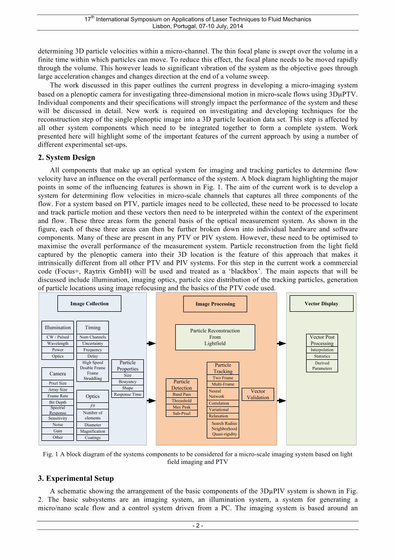
velocity have an influence on the overall performance of the system. A block diagram highlighting the major points in some of the influencing features is shown in Fig. 1. The aim of the current work is to develop a system for determining flow velocities in micro-scale channels that captures all three components of the flow. For a system based on PTV, particle images need to be collected, these need to be processed to locate and track particle motion and these vectors then need to be interpreted within the context of the experiment and flow. These three areas form the general basis of the optical measurement system. As shown in the figure, each of these three areas can then be further broken down into individual hardware and software components. Many of these are present in any PTV or PIV system. However, these need to be optimised to maximise the overall performance of the measurement system. Particle reconstruction from the light field captured by the plenoptic camera into their 3D location is the feature of this approach that makes it intrinsically different from all other PTV and PIV systems. For this step in the current work a commercial code (Focus+, Raytrix GmbH) will be used and treated as a ‘blackbox’. The main aspects that will be discussed include illumination, imaging optics, particle size distribution of the tracking particles, generation of particle locations using image refocusing and the basics of the PTV code used.
Fig. 1 A block diagram of the systems components to be considered for a micro-scale imaging system based on light
field imaging and PTV
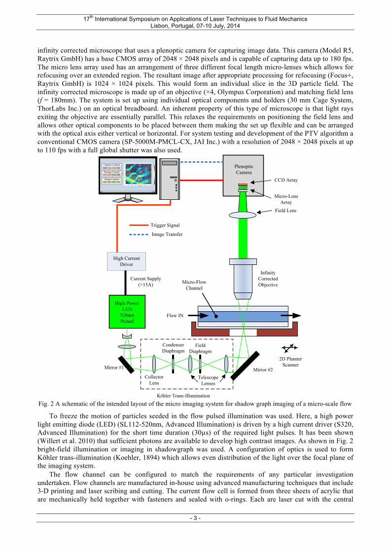
3. Experimental Setup A schematic showing the arrangement of the basic components of the 3DµPIV system is shown in Fig.
2. The basic subsystems are an imaging system, an illumination system, a system for generating a micro/nano scale flow and a control system driven from a PC. The imaging system is based around an
Image Collection Image Processing Vector Display
Particle ReconstructionFrom
Lightfield
Vector Validation
Particle Properties
SizeBouyancy
Response TimeShape
Optics
f/#Number of elementsDiameter
MagnificationCoatings
Camera
Pixel SizeArray SizeFrame RateBit Depth
SensitivityNoiseGainOther
Spectral Response
Illumination
CW / PulsedWavelength
PowerOptics
Timing
Num ChannelsUncertaintyFrequency
DelayHigh Speed
Double FrameFrame
Straddling Particle DetectionBand PassThreasholdMax PeakSub-Pixel
Particle Tracking
Relaxation
Neural NetworkCorrelationVariational
Search RadiusNeighborhoodQuasi-rigidity
Two FrameMulti-Frame
Vector Post ProcessingInterpolation
StatisticsDerived
Parameters
17th International Symposium on Applications of Laser Techniques to Fluid Mechanics Lisbon, Portugal, 07-10 July, 2014
- 3 -
infinity corrected microscope that uses a plenoptic camera for capturing image data. This camera (Model R5, Raytrix GmbH) has a base CMOS array of 2048 × 2048 pixels and is capable of capturing data up to 180 fps. The micro lens array used has an arrangement of three different focal length micro-lenses which allows for refocusing over an extended region. The resultant image after appropriate processing for refocusing (Focus+, Raytrix GmbH) is 1024 × 1024 pixels. This would form an individual slice in the 3D particle field. The infinity corrected microscope is made up of an objective (×4, Olympus Corporation) and matching field lens (f = 180mm). The system is set up using individual optical components and holders (30 mm Cage System, ThorLabs Inc.) on an optical breadboard. An inherent property of this type of microscope is that light rays exiting the objective are essentially parallel. This relaxes the requirements on positioning the field lens and allows other optical components to be placed between them making the set up flexible and can be arranged with the optical axis either vertical or horizontal. For system testing and development of the PTV algorithm a conventional CMOS camera (SP-5000M-PMCL-CX, JAI Inc.) with a resolution of 2048 × 2048 pixels at up to 110 fps with a full global shutter was also used.
Fig. 2 A schematic of the intended layout of the micro imaging system for shadow graph imaging of a micro-scale flow
To freeze the motion of particles seeded in the flow pulsed illumination was used. Here, a high power light emitting diode (LED) (SL112-520nm, Advanced Illumination) is driven by a high current driver (S320, Advanced Illumination) for the short time duration (30µs) of the required light pulses. It has been shown (Willert et al. 2010) that sufficient photons are available to develop high contrast images. As shown in Fig. 2 bright-field illumination or imaging in shadowgraph was used. A configuration of optics is used to form Köhler trans-illumination (Koehler, 1894) which allows even distribution of the light over the focal plane of the imaging system.
The flow channel can be configured to match the requirements of any particular investigation undertaken. Flow channels are manufactured in-house using advanced manufacturing techniques that include 3-D printing and laser scribing and cutting. The current flow cell is formed from three sheets of acrylic that are mechanically held together with fasteners and sealed with o-rings. Each are laser cut with the central
High Power LED
520nmPulsed
CollectorLens
Field Lens
Infinity Corrected Objective Micro-Flow
Channel
Plenoptic Camera
Condenser Diaphragm
Field Diaphragm
Telescope Lenses
Micro-Lens Array
Köhler Trans-Illumination
2D Planner Scanner
Flow IN
Start
Mirror #1
100
200
300
400
500
600
700
x (µm )
y(µ
m)
|V |(µm /s)Camera Control
Pump Control
Timing Control
Start Stop PlayGrab
Start Stop Trig Delay
Start Stop Rate Vol
Trigger Signal
Image Transfer
CCD Array
High Current Driver
Current Supply(>15A)
Mirror #2
17th International Symposium on Applications of Laser Techniques to Fluid Mechanics Lisbon, Portugal, 07-10 July, 2014
- 4 -
sheet through-cut to form the flow channel and side sheets cut to allow external flow access and to contain the flow. The current flow channel has dimensions of 1.0mm in height and is the thickness of the acrylic sheet (1.5mm) in depth. This form of flow channel manufacturing has been chosen to allow highly viscous, staining or corrosive fluids to be used in a one-shot single experiment. The fluid was seeded with hollow glass spheres (Sphericel 110P8, Potters Industry LLC) to track the fluid. Fluid motion was either by gravity from a reservoir or using a syringe pump (PHD2000, Harvard Apparatus) for high viscosity fluids.
Data collected in the form of single light field images will be reconstructed into 3D particle position data sets. This will be carried out using commercial (Focus+, Raytrix GmbH) code. Custom code for both 2D and 3D PTV (Matlab, MathWorks Inc.) has been developed in-house to process volume datasets into three component three-dimensional (3C3D) velocity fields.
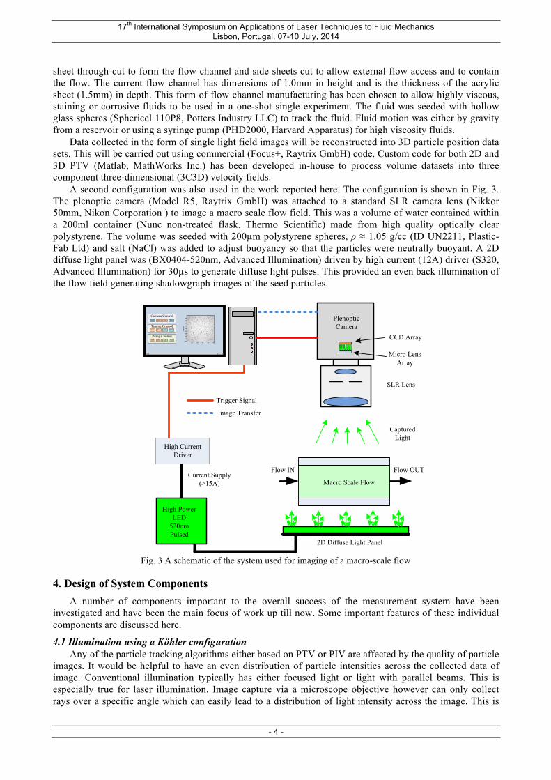
A second configuration was also used in the work reported here. The configuration is shown in Fig. 3. The plenoptic camera (Model R5, Raytrix GmbH) was attached to a standard SLR camera lens (Nikkor 50mm, Nikon Corporation ) to image a macro scale flow field. This was a volume of water contained within a 200ml container (Nunc non-treated flask, Thermo Scientific) made from high quality optically clear polystyrene. The volume was seeded with 200µm polystyrene spheres, ρ ≈ 1.05 g/cc (ID UN2211, Plastic-Fab Ltd) and salt (NaCl) was added to adjust buoyancy so that the particles were neutrally buoyant. A 2D diffuse light panel was (BX0404-520nm, Advanced Illumination) driven by high current (12A) driver (S320, Advanced Illumination) for 30µs to generate diffuse light pulses. This provided an even back illumination of the flow field generating shadowgraph images of the seed particles.
Fig. 3 A schematic of the system used for imaging of a macro-scale flow
4. Design of System Components A number of components important to the overall success of the measurement system have been
investigated and have been the main focus of work up till now. Some important features of these individual components are discussed here.
4.1 Illumination using a Köhler configuration Any of the particle tracking algorithms either based on PTV or PIV are affected by the quality of particle
images. It would be helpful to have an even distribution of particle intensities across the collected data of image. Conventional illumination typically has either focused light or light with parallel beams. This is especially true for laser illumination. Image capture via a microscope objective however can only collect rays over a specific angle which can easily lead to a distribution of light intensity across the image. This is
High Power LED
520nmPulsed
Macro Scale Flow
PlenopticCamera
Flow IN
Start
Camera Control
Pump Control
Timing Control
Start Stop PlayGrab
Start Stop Trig Delay
Start Stop Rate Vol
Trigger Signal
Image Transfer
SLR Lens
CCD Array
High Current Driver
Current Supply(>15A)
Micro Lens Array
Flow OUT
Captured Light
2D Diffuse Light Panel
17th International Symposium on Applications of Laser Techniques to Fluid Mechanics Lisbon, Portugal, 07-10 July, 2014
- 5 -
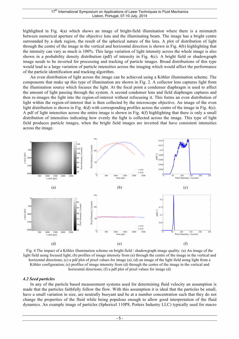
highlighted in Fig. 4(a) which shows an image of bright-field illumination where there is a mismatch between numerical aperture of the objective lens and the illuminating beam. The image has a bright centre surrounded by a dark region, the result of the spherical nature of the lens. A plot of distribution of light through the centre of the image in the vertical and horizontal direction is shown in Fig. 4(b) highlighting that the intensity can vary as much is 100%. This large variation of light intensity across the whole image is also shown in a probability density distribution (pdf) of intensity in Fig. 4(c). A bright field or shadowgraph image needs to be inverted for processing and tracking of particle images. Broad distributions of this type would lead to a large variation of particle intensities across the imaging which would affect the performance of the particle identification and tracking algorithm.
An even distribution of light across the image can be achieved using a Köhler illumination scheme. The components that make up this type of illumination are shown in Fig. 2. A collector lens captures light from the illumination source which focuses the light. At the focal point a condenser diaphragm is used to affect the amount of light passing through the system. A second condenser lens and field diaphragm captures and then re-images the light into the region-of-interest without refocusing it. This forms an even distribution of light within the region-of-interest that is then collected by the microscope objective. An image of the even light distribution is shown in Fig. 4(d) with corresponding profiles across the centre of the image in Fig. 4(e). A pdf of light intensities across the entire image is shown in Fig. 4(f) highlighting that there is only a small distribution of intensities indicating how evenly the light is collected across the image. This type of light field produces particle images, when the bright field images are inverted that have consistent intensities across the image.
(a) (b) (c)
(d) (e) (f)
Fig. 4 The impact of a Köhler illumination scheme on bright field / shadowgraph image quality. (a) An image of the light field using focused light; (b) profiles of image intensity from (a) through the centre of the image in the vertical and
horizontal directions; (c) a pdf plot of pixel values for image (a); (d) an image of the light field using light from a Köhler configuration; (e) profiles of image intensity from (d) through the centre of the image in the vertical and
horizontal directions; (f) a pdf plot of pixel values for image (d)
4.2 Seed particles In any of the particle based measurement systems used for determining fluid velocity an assumption is
made that the particles faithfully follow the flow. With this assumption it is ideal that the particles be small, have a small variation in size, are neutrally buoyant and be at a number concentration such that they do not change the properties of the fluid while being populous enough to allow good interpretation of the fluid dynamics. An example image of particles (Sphericel 110P8, Potters Industry LLC) typically used for macro
x-axis (px)
y-ax
is (p
x)
500 1000 1500 2000 2500
0
500
1000
1500
2000
Pixe
l Int
ensi
ty, I
(cou
nt)
20
40
60
80
100
120
140
0 500 1000 1500 2000 25000
50
100
150
Axis (px)
Pixe
l Int
ensi
ty, I
(cou
nt)
x-axisy-axis
0 50 100 150 200 2500
0.002
0.004
0.006
0.008
0.01
0.012
0.014
Pixel Intensity, I (count)
pdf(
I )
x-axis (px)
y-ax
is (p
x)
500 1000 1500 2000 2500
0
500
1000
1500
2000
Pixe
l Int
ensi
ty, I
(cou
nt)
10
20
30
40
50
60
0 500 1000 1500 2000 25000
50
100
150
Axis (px)
Pixe
l Int
ensi
ty, I
(cou
nt)
x-axisy-axis
0 50 100 150 200 2500
0.05
0.1
0.15
0.2
Pixel Intensity, I (count)
pdf(
I )
17th International Symposium on Applications of Laser Techniques to Fluid Mechanics Lisbon, Portugal, 07-10 July, 2014
- 6 -
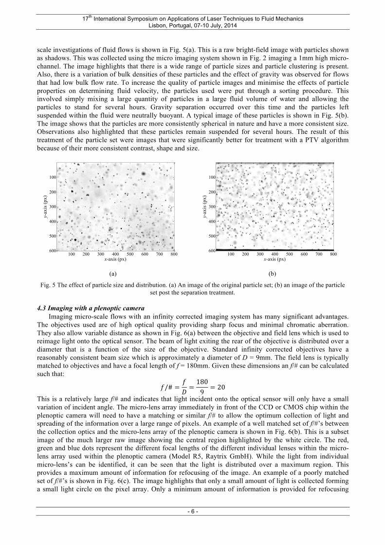
scale investigations of fluid flows is shown in Fig. 5(a). This is a raw bright-field image with particles shown as shadows. This was collected using the micro imaging system shown in Fig. 2 imaging a 1mm high micro-channel. The image highlights that there is a wide range of particle sizes and particle clustering is present. Also, there is a variation of bulk densities of these particles and the effect of gravity was observed for flows that had low bulk flow rate. To increase the quality of particle images and minimise the effects of particle properties on determining fluid velocity, the particles used were put through a sorting procedure. This involved simply mixing a large quantity of particles in a large fluid volume of water and allowing the particles to stand for several hours. Gravity separation occurred over this time and the particles left suspended within the fluid were neutrally buoyant. A typical image of these particles is shown in Fig. 5(b). The image shows that the particles are more consistently spherical in nature and have a more consistent size. Observations also highlighted that these particles remain suspended for several hours. The result of this treatment of the particle set were images that were significantly better for treatment with a PTV algorithm because of their more consistent contrast, shape and size.
(a) (b)
Fig. 5 The effect of particle size and distribution. (a) An image of the original particle set; (b) an image of the particle set post the separation treatment.
4.3 Imaging with a plenoptic camera Imaging micro-scale flows with an infinity corrected imaging system has many significant advantages.
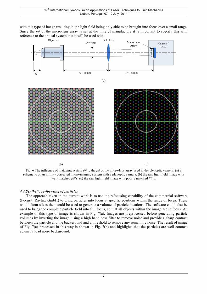
The objectives used are of high optical quality providing sharp focus and minimal chromatic aberration. They also allow variable distance as shown in Fig. 6(a) between the objective and field lens which is used to reimage light onto the optical sensor. The beam of light exiting the rear of the objective is distributed over a diameter that is a function of the size of the objective. Standard infinity corrected objectives have a reasonably consistent beam size which is approximately a diameter of D = 9mm. The field lens is typically matched to objectives and have a focal length of f = 180mm. Given these dimensions an f/# can be calculated such that:
𝑓/# =𝑓𝐷=1809
= 20
This is a relatively large f/# and indicates that light incident onto the optical sensor will only have a small variation of incident angle. The micro-lens array immediately in front of the CCD or CMOS chip within the plenoptic camera will need to have a matching or similar f/# to allow the optimum collection of light and spreading of the information over a large range of pixels. An example of a well matched set of f/#’s between the collection optics and the micro-lens array of the plenoptic camera is shown in Fig. 6(b). This is a subset image of the much larger raw image showing the central region highlighted by the white circle. The red, green and blue dots represent the different focal lengths of the different individual lenses within the micro-lens array used within the plenoptic camera (Model R5, Raytrix GmbH). While the light from individual micro-lens’s can be identified, it can be seen that the light is distributed over a maximum region. This provides a maximum amount of information for refocusing of the image. An example of a poorly matched set of f/#’s is shown in Fig. 6(c). The image highlights that only a small amount of light is collected forming a small light circle on the pixel array. Only a minimum amount of information is provided for refocusing
x-axis (px)
y-ax
is (p
x)
100 200 300 400 500 600 700 800
100
200
300
400
500
600
x-axis (px)
y-ax
is (p
x)
100 200 300 400 500 600 700 800
100
200
300
400
500
600
17th International Symposium on Applications of Laser Techniques to Fluid Mechanics Lisbon, Portugal, 07-10 July, 2014
- 7 -
with this type of image resulting in the light field being only able to be brought into focus over a small range. Since the f/# of the micro-lens array is set at the time of manufacture it is important to specify this with reference to the optical system that it will be used with.
(a)
(b) (c)
Fig. 6 The influence of matching system f/# to the f/# of the micro-lens array used in the plenoptic camera. (a) a schematic of an infinity corrected micro-imaging system with a plenoptic camera; (b) the raw light field image with
well-matched f/#’s; (c) the raw light field image with poorly matched f/#’s.
4.4 Synthetic re-focusing of particles The approach taken in the current work is to use the refocusing capability of the commercial software
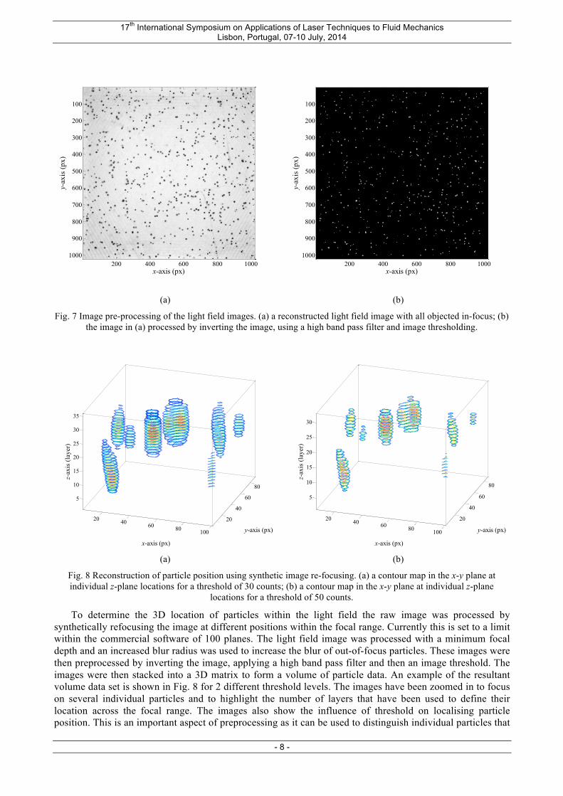
(Focus+, Raytrix GmbH) to bring particles into focus at specific positions within the range of focus. These would form slices then could be used to generate a volume of particle locations. The software could also be used to bring the complete particle field into full focus, so that all objects within the image are in focus. An example of this type of image is shown in Fig. 7(a). Images are preprocessed before generating particle volumes by inverting the image, using a high band pass filter to remove noise and provide a sharp contrast between the particle and the background and a threshold to remove any remaining noise. The result of image of Fig. 7(a) processed in this way is shown in Fig. 7(b) and highlights that the particles are well contrast against a load noise background.
70-170mm f = 180mmWD
Field LensObjectiveCamera /
CCDD ≈ 9mm Micro Lens
Array
17th International Symposium on Applications of Laser Techniques to Fluid Mechanics Lisbon, Portugal, 07-10 July, 2014
- 8 -
(a) (b)
Fig. 7 Image pre-processing of the light field images. (a) a reconstructed light field image with all objected in-focus; (b) the image in (a) processed by inverting the image, using a high band pass filter and image thresholding.
(a) (b)
Fig. 8 Reconstruction of particle position using synthetic image re-focusing. (a) a contour map in the x-y plane at individual z-plane locations for a threshold of 30 counts; (b) a contour map in the x-y plane at individual z-plane
locations for a threshold of 50 counts.
To determine the 3D location of particles within the light field the raw image was processed by synthetically refocusing the image at different positions within the focal range. Currently this is set to a limit within the commercial software of 100 planes. The light field image was processed with a minimum focal depth and an increased blur radius was used to increase the blur of out-of-focus particles. These images were then preprocessed by inverting the image, applying a high band pass filter and then an image threshold. The images were then stacked into a 3D matrix to form a volume of particle data. An example of the resultant volume data set is shown in Fig. 8 for 2 different threshold levels. The images have been zoomed in to focus on several individual particles and to highlight the number of layers that have been used to define their location across the focal range. The images also show the influence of threshold on localising particle position. This is an important aspect of preprocessing as it can be used to distinguish individual particles that
x-axis (px)
y-ax
is (p
x)
200 400 600 800 1000
100
200
300
400
500
600
700
800
900
1000
x-axis (px)
y-ax
is (p
x)
200 400 600 800 1000
100
200
300
400
500
600
700
800
900
1000
20 40 60 80 100
20
40
60
80
5
10
15
20
25
30
35
z-ax
is (l
ayer
)
x-axis (px)
y-axis (px)
20 40 60 80 100
20
40
60
80
5
10
15
20
25
30
z-ax
is (l
ayer
)
x-axis (px)
y-axis (px)
17th International Symposium on Applications of Laser Techniques to Fluid Mechanics Lisbon, Portugal, 07-10 July, 2014
- 9 -
are close together both in the in-plane and out-of-plane directions. These stacks of images are used as input into the particle detection section of the PTV algorithm.
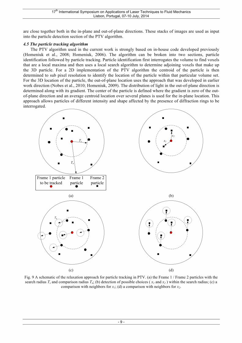
4.5 The particle tracking algorithm The PTV algorithm used in the current work is strongly based on in-house code developed previously
(Homeniuk et al., 2008; Homeniuk, 2006). The algorithm can be broken into two sections, particle identification followed by particle tracking. Particle identification first interrogates the volume to find voxels that are a local maxima and then uses a local search algorithm to determine adjoining voxels that make up the 3D particle. For a 2D implementation of the PTV algorithm the centroid of the particle is then determined to sub pixel resolution to identify the location of the particle within that particular volume set. For the 3D location of the particle, the out-of-plane location uses the approach that was developed in earlier work direction (Nobes et al., 2010; Homeniuk, 2009). The distribution of light in the out-of-plane direction is determined along with its gradient. The center of the particle is defined where the gradient is zero of the out-of-plane direction and an average centroid location over several planes is used for the in-plane location. This approach allows particles of different intensity and shape affected by the presence of diffraction rings to be interrogated.
(a) (b)
(c) (d)
Fig. 9 A schematic of the relaxation approach for particle tracking in PTV. (a) the Frame 1 / Frame 2 particles with the search radius Ts and comparison radius Tn; (b) detection of possible choices ( x1 and x2 ) within the search radius; (c) a
comparison with neighbors for x1; (d) a comparison with neighbors for x2.
Tn
Ts
Frame 2 particle
Frame 1 particle to be tracked
Frame 1 particle
x1
x2
Tq
17th International Symposium on Applications of Laser Techniques to Fluid Mechanics Lisbon, Portugal, 07-10 July, 2014
- 10 -
The particle tracking approach is based on a two-frame relaxation method (Baek and Lee, 1996). The algorithm uses a search radius Ts to look for corresponding particles of a Frame 1 particle in the second frame. This is shown schematically in Fig. 9(a). Particles within the search radius in the second frame are all viable solutions as shown in Fig. 9(b). To determine the correct choice of particle the displacement vectors to the second frame particle from the first frame particle are individually compared with the particles within a neighborhood radius Tn as shown in Fig. 9(c,d). The correct particle trajectory is determined as the one in which neighborhood particles have a similar trajectory. For this case the solution is shown in Fig. 9(d). A quasi-rigid radius Tq at the end of the trajectory use used to allow subtle variation between individual particle trajectories. In locations where there are low particle counts within the neighborhood a nearest neighbor approach is used. This algorithm has been developed for both 2D and 3D flow fields (Homeniuk et al., 2008; Homeniuk, 2006).
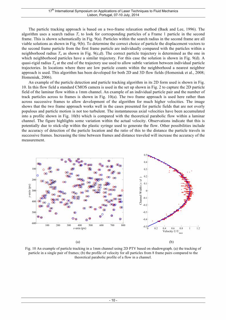
An example of the particle detection and particle tracking algorithm in its 2D form used is shown in Fig. 10. In this flow field a standard CMOS camera is used in the set up shown in Fig. 2 to capture the 2D particle field of the laminar flow within a 1mm channel. An example of an individual particle pair and the number of track particles across to frames is shown in Fig. 10(a). The two frame approach is used here rather than across successive frames to allow development of the algorithm for much higher velocities. The image shows that the two frame approach works well in the cases presented for particle fields that are not overly populous and particle motion is not too turbulent. The instantaneous axial velocities have been accumulated into a profile shown in Fig. 10(b) which is compared with the theoretical parabolic flow within a laminar channel. The figure highlights some variation within the actual velocity. Observations indicate that this is potentially due to stick-slip within the plastic syringe used to generate the flow. Other possibilities include the accuracy of detection of the particle location and the ratio of this to the distance the particle travels in successive frames. Increasing the time between frames and distance traveled will increase the accuracy of the measurement.
(a) (b)
Fig. 10 An example of particle tracking in a 1mm channel using 2D PTV based on shadowgraph. (a) the tracking of particle in a single pair of frames; (b) the profile of velocity for all particles from 8 frame pairs compared to the
theoretical parabolic profile of a flow in a channel.
x-axis (px)
y-ax
is (p
x)
100 200 300 400 500 600 700 800
100
200
300
400
500
600
0 0.2 0.4 0.6 0.8 1 1.2-0.5
-0.4
-0.3
-0.2
-0.1
0
0.1
0.2
0.3
0.4
0.5
Velocity U/Umax
Cha
nnel
Wid
th (
x /d
)
17th International Symposium on Applications of Laser Techniques to Fluid Mechanics Lisbon, Portugal, 07-10 July, 2014
- 11 -
5. Results The current plenoptic camera has a mismatch of f/#’s with the infinity corrected imaging system. This
hardware will be corrected in the future. Development of the system for micro-imaging however is continuing. To investigate the performance of light field imaging and processing through to 3D velocity fields the macro-scale system shown in Fig. 3 has been used. This allows collection of the light field, preprocessing into sets of refocused image planes to form data volumes and processing with the 3D PTV algorithm to generate 3C3D velocity sets. The example used here is a random swirling flow generated within a rectangular culture chamber.
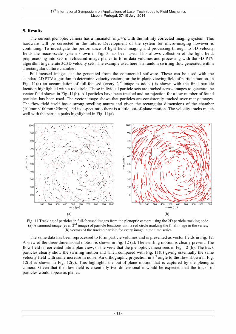
Full-focused images can be generated from the commercial software. These can be used with the standard 2D PTV algorithm to determine velocity vectors for the in-plane viewing field of particle motion. In Fig. 11(a) an accumulation of full-focused (every 2nd image is added) is shown with the final particle location highlighted with a red circle. These individual particle sets are tracked across images to generate the vector field shown in Fig. 11(b). All particles have been tracked and no rejection for a low number of found particles has been used. The vector image shows that particles are consistently tracked over many images. The flow field itself has a strong swelling nature and given the rectangular dimensions of the chamber (100mm×100mm×25mm) and its aspect ratio there is a little out-of-plane motion. The velocity tracks match well with the particle paths highlighted in Fig. 11(a)
(a) (b)
Fig. 11 Tracking of particles in full-focused images from the plenoptic camera using the 2D particle tracking code. (a) A summed image (even 2nd image) of particle locations with a red circle marking the final image in the series;
(b) vectors of the tracked particle for every image in the time series
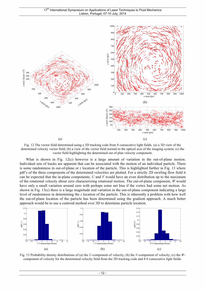
The same data has been reprocessed to form particle volumes and is presented as vector fields in Fig. 12. A view of the three-dimensional motion is shown in Fig. 12 (a). The swirling motion is clearly present. The flow field is reoriented into a plan view, or the view that the plenoptic camera sees in Fig. 12 (b). The track particles clearly show the swirling motion and when compared with Fig. 11(b) giving essentially the same velocity field with some increase in noise. An orthographic projection in 3rd angle to the flow shown in Fig. 12(b) is shown in Fig. 12(c). This highlights the out-of-plane motion that is captured by the plenoptic camera. Given that the flow field is essentially two-dimensional it would be expected that the tracks of particles would appear as planes.
numIM = 17
x-axis (px)
y-ax
is (p
x)
100 200 300 400 500 600 700 800 900 1000
100
200
300
400
500
600
700
800
900
1000
100 200 300 400 500 600 700 800 900 1000
100
200
300
400
500
600
700
800
900
1000
x-axis (px)
y-ax
is (p
x)
17th International Symposium on Applications of Laser Techniques to Fluid Mechanics Lisbon, Portugal, 07-10 July, 2014
- 12 -
(b)
(a) (c)
Fig. 12 The vector field determined using a 3D tracking code from 8 consecutive light fields. (a) a 3D view of the determined velocity vector field; (b) a view of the vector field normal to the optical axis of the imaging system; (c) the
vector field highlighting the determined out of plan velocity component.
What is shown in Fig. 12(c) however is a large amount of variation in the out-of-plane motion. Individual sets of tracks are apparent that can be associated with the motion of an individual particle. There is some randomness in out-of-plane or z location of the particle. This is highlighted further in Fig. 13 where pdf’s of the three components of the determined velocities are plotted. For a strictly 2D swirling flow field it can be expected that the in-plane components, U and V would have an even distribution up to the maximum of the rotational velocity about zero characterizing rotational motion. The out-of-plane component, W would have only a small variation around zero with perhaps some net bias if the vortex had some net motion. As shown in Fig. 13(c) there is a large magnitude and variation in the out-of-plane component indicating a large level of randomness in determining the z location of the particle. This is inherently a problem with how well the out-of-plane location of the particle has been determined using the gradient approach. A much better approach would be to use a centroid method over 3D to determine particle location.
(a) (b) (c)
Fig. 13 Probability density distributions of (a) the U-component of velocity; (b) the V-component of velocity; (c) the W-component of velocity for the determined velocity field from the 3D tracking code and 8 8 consecutive light fields.
200
400
600
800
1000
200
400
600
800
1000
100200300
y-axis (
px)x-axis (px)
z-ax
is (l
ayer
x3)
0 100 200 300 400 500 600 700 800 900 10000
100
200
300
400
500
600
700
800
900
1000
x-axis (px)
y-ax
is (p
x)
100 200 300 400 500 600 700 800 900 1000
50100150200250300
x-axis (px)
z-ax
is (l
ayer
x3)
-15 -10 -5 0 5 10 15 20 250
0.02
0.04
0.06
0.08
0.1
0.12
U Component(px/frame)
pdf( U
)
-20 -15 -10 -5 0 5 10 15 200
0.02
0.04
0.06
0.08
0.1
V Component(px/frame)
pdf( V
)
-20 -15 -10 -5 0 5 10 15 200
0.02
0.04
0.06
0.08
0.1
0.12
0.14
0.16
W Component(px/frame)
pdf( W
)
17th International Symposium on Applications of Laser Techniques to Fluid Mechanics Lisbon, Portugal, 07-10 July, 2014
- 13 -
6. Conclusions The design and a number of individual components of a 3DµPTV system based on light field imaging
for micro-imaging applications have been discussed. A bright field or shadowgraph approach to imaging particles has been used, providing clear images of particles. These particles have been prescreened to minimise the variation in particle size and ensure that they are neutrally buoyant. A two frame PTV algorithm has been implemented for both 2D and 3D datasets based on a relaxation algorithm. The algorithm consistently tracks particles for the datasets collected. The importance of matching the f/# of the imaging system whether it be micro or macro-scale scenes to the f/# of the micro-lens array built into the plenoptic camera has also been highlighted. The limitation of the current plenoptic camera to low f/# applications has resulted in it being restricted to macro-scale investigations. This hardware is currently under review. The result 3D velocity field highlights that the future main focus of research will be on determining the out-of-plane position of particles. This is an intrinsic function of the algorithm used for research focusing the light field image and the method used for determining the location of the particle in 3D.
8. Acknowledgements The authors acknowledge funding support for this research from the Alberta Ingenuity Fund, the Natural
Sciences and Research Council (NSERC) of Canada, and the Canadian Foundation for Innovation.
7. References Baek, S.J., and Lee, S.J. (1996) A new two-frame particle tracking algorithm using match probability,
Experiments in Fluids. Volume 22, pages 23-32 Gabor, D. 1948. A new microscopic principle. Nature 161, 777-778. Günther, A., Khan, S. A., Thalmann, M., Trachsel, F., and Jensen, K. F. (2004). Transport and reaction
in microscale segmented gas-liquid flow. Lab on a Chip, 4(4), 278-286. Royal Society of Chemistry Koehler, A. (1894) New Method of Illimination for Phomicrographical Purposes, Journal of the Royal
Microscopical Society, 14: 261–262. Homeniuk, D.L.N., Nobes, D.S. and Wilson, D. J. (2008) Three-Dimensional Particle Tracking
Velocimetry, The Canadian Society for Mechanical Engineers (CSME) Forum, Ottawa, Ontario, Canada, June 5-8, 2008
Homeniuk, D.L.N., Nobes, D.S., Molla, S. and Bhattacharjee, S. (2008) Volume particle tracking in three-dimensional micro-channel flows, 6th Joint ASME/JSME Fluids Engineering Conference (FEDSM2008), Jacksonville, Florida, USA, August 10-14, 2008
Homeniuk, D.L.N. (2009) Development and Testing of Macro and Micro Three-Dimensional Particle Tracking Systems, M.Sc. Thesis, The Department of Mechanical Engineering, University of Alberta, Edmonton, Canada.
Levoy, M., Ng, R., Adams, A., Footer, M. and Horowitz, M. (2006) Light field microscopy. ACM Trans. on Graphics (Proc. SIGGRAPH) 25(3), 924– 934.
Lynch, K., Fahringer, T., Thurow, B. (2013) Three-Dimensional Particle Image Velocimetry Using a Plenoptic Camera, AIAA Paper 2012-1056, 50th AIAA Aerospace Sciences Meeting Nashville, Tennessee, January 2012
Masliyah J.H. and Bhattacharjee S. (2006) Electrokinetic and Colloid Transport Phenomena, John Wiley and Sons, Hoboken New Jersey, (ISBN:978-0-471-78882-9) pp. 736.
Nobes, D.S., Abdolrazaghi, M. and Homeniuk, D.L.N. (2010) Three-component, three-dimensional velocity measurement technique for micro-channel applications using a scanning µPIV, 15th International Symposium on Applications of Laser Techniques to Fluid Mechanics, Lisbon Portugal, July 5-8, 2010.
Okoshi, T. 1976. Three-Dimensional Imaging Techniques. Academic Press. Sen, D., Nobes, D.S. and Mitra, S.K. (2012) Optical measurement of pore scale velocity field inside
micro porous media, Microfluidics and Nanofluidics, Vol. 12, pp. 189-200 Willert, C., Stasicki, B., Klinner, J. and Moessner, S. (2010), Pulsed operation of high-power light
emitting diodes for imaging flow velocimetry, (2010) Meas. Sci. Technol. 21 075402 doi:10.1088/0957-0233/21/7/075402