a swirl generator design approach to increase the...
TRANSCRIPT

17th International Symposium on Applications of Laser Techniques to Fluid Mechanics Lisbon, Portugal, 07-10 July, 2014
- 1 -
A swirl generator design approach to increase the efficiency of uniflow cyclones
Martin Pillei1,*, Tobias Kofler1 and Michael Kraxner1
1: Department of Environmental, Process & Energy Engineering, MCI - The Entrepreneurial School,
Innsbruck, Austria * correspondent author: [email protected]
Abstract Uniflow cyclones used for the separation of particles from a gaseous phase are characterized, compared to standard reverse flow cyclones, by its compactness and a low energy consumption. Benefits may result from the compact design and the low pressure drop which gives plant operators the possibility of easy implementation in existing piping systems. The used swirl generator consists of several curved blades circular arranged around a cylindrical core. The blade profile has a major influence on the uniflow cyclone performance. Greatly skewed swirl vanes result in high collection efficiencies but also in a high pressure drop, whereas curved swirl vanes lead to a reciprocally behavior. In comparison to a standard swirl generator setup the here used vane channel consists additionally of an inlet and outlet section for the purpose of flow harmonization. To ensure optical accessibility for the PIV measurements the vane pack has been uncoiled. The results show that the shortening of the guide vans leads to a detachment of the flow at the backside of the vanes. This phenomenon leads to a minimization of the cross-section area for the flow and increases the velocity within the vane channel. The unshortened vane is responsible for a smooth transition of the flow from the inlet section into the vane channel and therefore for a nearly constant pressure drop over the vane pack. The results show that the relative change of the velocity distribution within the vane channel has a significant effect on the particle emission and the pressure drop of the dust collector. The comparison between numerical calculation (CFD) and PIV measurement data shows good agreement and an optimized length ratio could be identified in the range of about 0,25 kSVI/LSVI. In this length ratio the highest collection efficiency has been measured. A further increase of the length ratio can compensate this positive effect. Especially coarse particles with high mass and therefore high inertial forces can pass the vane pack without deflection. As a result the collection efficiency is reduced due to higher particle emission. 1. Introduction Uniflow cyclones used for separation have gas and particles passing through them in only one direction. They are characterized - compared to the standard reverse flow cyclone - by a compact design, a low pressure drop and the ability to easy retrofit into existing piping systems. The scope of this paper is to describe the flow pattern in a standard swirl generator and a new geometrical design approach of a uniflow cyclone to increase the collection efficiency and decrease the pressure drop. [2, 6, 9] The swirl generator consists of several curved blades arranged circular around a cylindrical core and is responsible for the swirl (centrifugal forces) and therefore for the separation of the particles. Preliminary dedusting tests presented on the AIChE 2012 Annual Meeting show a significant optimization potential. [5] For further investigations dedusting tests were made and to examine the flow field particle image velocimetry (2C-PIV) measurements and CFD simulations have been carried out. [7] To reduce the experimental effort a CFD sensitivity study has been performed to identify tendencies. The observed characteristics are the collection efficiency, the pressure drop and the velocity distribution. 2. Experimental In comparison to a standard swirl generator the here used vane channel consists additionally of an inlet and an outlet section for flow harmonization. The inlet section is connected in upstream direction to the vane channel to reduce distortions from the inlet geometry. Downstream a laminator, a filter unit, a calibrated orifice plate and an air blower for the desired flow rate are attached. Fig. 1 shows the main dimensions and the modified parameters.

17th International Symposium on Applications of Laser Techniques to Fluid Mechanics Lisbon, Portugal, 07-10 July, 2014
- 2 -
The present vane pack consists of five blades with a mean vane angle αSVI of 45°, a vane blade thickness s of 2 mm, a swirl vane blade overlap o of zero, and a vane pack length LSVI of 32 mm, see Fig. 1.
Fig. 1 Geometry dimensions To ensure optical accessibility for the PIV measurements the vane pack has been uncoiled. The material for the laser entry window and the front plate is made of acrylic glass whereas the back plate and the vane pack are manufactured by a rapid prototyping system with accurateness of about 45 µm. Fig. 2 describes the method on how the vane pack is unfolded and describes the position of the extraction plane. The extraction plane is located at the middle diameter (DC+Dcore)/2 of the swirl generator. [7]
Fig. 2 Uncoiling of the vane pack The air blower is controlled by a calibrated orifice plate with a volume flow of 240 m3/h which corresponds to a Reynolds number of about 21.000. This Reynolds number range is defined as turbulent flow and is measured according to DIN EN ISO 5167-1:2004-01 (Measurement of fluid flow by means of pressure differential devices). Additionally the parts are coated matte black to reduce reflections from the illumination and to ensure a good image quality for the PIV image data analysis, see Tab. 1. [3, 7]

17th International Symposium on Applications of Laser Techniques to Fluid Mechanics Lisbon, Portugal, 07-10 July, 2014
- 3 -
Configuration Value
Laser Type Nd:YAG Frequency 532 nm-1 Puls distance 18 µm
Optics Aperture f4.0 Camera Setup 2C
Tab. 1 Main parameters for the 2C-PIV measurements
For the illumination of the flow dioctyl sebacate (DEHS) is used as tracer fluid. The laskin nozzles from the seeding generator produce particles with a modal diameter of approx. 1 µm and follow the fluid nearly without drag effects. The light sheet is produced by a double pulsed Nd:YAG laser. The main parameters are listed in Tab.1.
Fig. 3 a) Laser sheet illumination from several sources, b) Shadowing effects due to partial illumination
The 2C-Measurement is calibrated by a 2C target with an 2x2 mm cross-hair spaced 3 mm equally in both directions. The used camera (pco.2000) has a sensor size of 2048x2048 Pixels which corresponds to a good resolution of about 15 Pixels/mm at a focal length for the objective lens of 50 mm and an operating distance of about 500 mm. To avoid distortion effects in the peripheral zone of the optical lens only one vane channel is observed centered in the sensor field. Due to the fact, that the cross section area in every vane channel is equivalent, this simplification is allowed. [1] The pulse distance is set to 15 µm to reach a particle displacement of about 8 pixels between the two image frames at a mean velocity of 30 m/s. [8] The cross-correlation calculation is performed by PivView. A recording series consists of at least 100 double images. Fig. 4 and Fig. 5 describes the results of the comparison between the PIV data and the CFD simulated velocity distribution at an shortened vane and kSVI/LSVI of 0,75. LSVI describes the length of the swirl generator and kSVI the shortening of the vanes measured from the entrance.
Fig. 4 Comparison of the velocity distribution between unshortened vanes with CFD and PIV, v/vmax
a) b)
Source 1 Source 2
17th International Symposium on Applications of Laser Techniques to Fluid Mechanics Lisbon, Portugal, 07-10 July, 2014
- 4 -
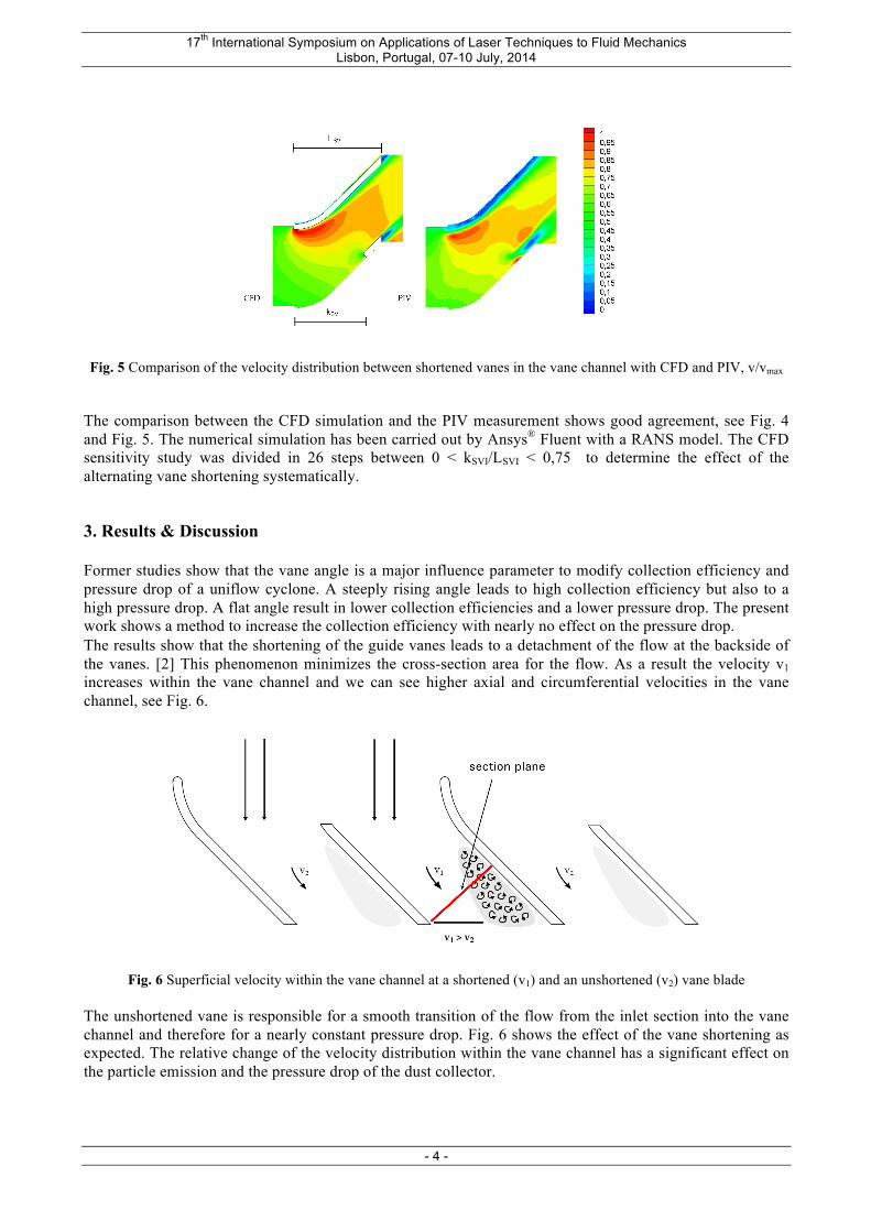
Fig. 5 Comparison of the velocity distribution between shortened vanes in the vane channel with CFD and PIV, v/vmax
The comparison between the CFD simulation and the PIV measurement shows good agreement, see Fig. 4 and Fig. 5. The numerical simulation has been carried out by Ansys® Fluent with a RANS model. The CFD sensitivity study was divided in 26 steps between 0 < kSVI/LSVI < 0,75 to determine the effect of the alternating vane shortening systematically. 3. Results & Discussion Former studies show that the vane angle is a major influence parameter to modify collection efficiency and pressure drop of a uniflow cyclone. A steeply rising angle leads to high collection efficiency but also to a high pressure drop. A flat angle result in lower collection efficiencies and a lower pressure drop. The present work shows a method to increase the collection efficiency with nearly no effect on the pressure drop. The results show that the shortening of the guide vanes leads to a detachment of the flow at the backside of the vanes. [2] This phenomenon minimizes the cross-section area for the flow. As a result the velocity v1 increases within the vane channel and we can see higher axial and circumferential velocities in the vane channel, see Fig. 6.
Fig. 6 Superficial velocity within the vane channel at a shortened (v1) and an unshortened (v2) vane blade
The unshortened vane is responsible for a smooth transition of the flow from the inlet section into the vane channel and therefore for a nearly constant pressure drop. Fig. 6 shows the effect of the vane shortening as expected. The relative change of the velocity distribution within the vane channel has a significant effect on the particle emission and the pressure drop of the dust collector.
17th International Symposium on Applications of Laser Techniques to Fluid Mechanics Lisbon, Portugal, 07-10 July, 2014
- 5 -
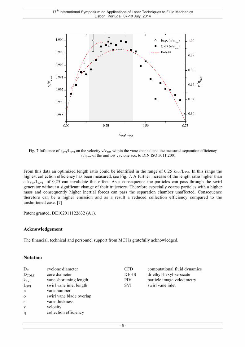
Fig. 7 Influence of kSVI/LSVI on the velocity v/vmax within the vane channel and the measured separation efficiency η/ηmax of the uniflow cyclone acc. to DIN ISO 5011:2001
From this data an optimized length ratio could be identified in the range of 0,25 kSVI/LSVI. In this range the highest collection efficiency has been measured, see Fig. 7. A further increase of the length ratio higher than a kSVI/LSVI of 0,25 can invalidate this effect. As a consequence the particles can pass through the swirl generator without a significant change of their trajectory. Therefore especially coarse particles with a higher mass and consequently higher inertial forces can pass the separation chamber unaffected. Consequence therefore can be a higher emission and as a result a reduced collection efficiency compared to the unshortened case. [7] Patent granted, DE102011122632 (A1). Acknowledgement The financial, technical and personnel support from MCI is gratefully acknowledged. Notation DC cyclone diameter CFD computational fluid dynamics DCORE core diameter DEHS di-ethyl-hexyl-sebacate kSVI vane shortening length PIV particle image velocimetry LSVI swirl vane inlet length SVI swirl vane inlet n vane number o swirl vane blade overlap s vane thickness v velocity η collection efficiency

17th International Symposium on Applications of Laser Techniques to Fluid Mechanics Lisbon, Portugal, 07-10 July, 2014
- 6 -
References [1] Beaulieu S, Deschenes C, Iliescu M, Fraser R (2009) Flow field measurement through the runner of
a propeller turbine using stereoscopic piv. Eight International Symposium on Particle Image Velocimetry (PIV 09).
[2] Hoffmann AC, Stein LE (2002) Gas Cyclones and Swirl Tubes – Principles, Design and Operation. Springer. Berlin.
[3] ISO 5011:2000 Inlet air cleaning equipment for internal combustion engines and compressors – Performance testing.
[4] Kraxner M (2013) Empirical Evaluation of Design Criterias for Uniflow Cyclones in Multicycloneboxes. Phd Thesis. TU München.
[5] Kraxner M, Muschelknautz U, Wechner S, Ackermann S, Greif V, Bolda J, Sommer K (2012) Influence of Inlet Vane geometry on the uniflow cyclones performance (639f). AIChE 2012 Annual Meeting.
[6] Muschelknautz U (2006) Zyklone zum Abscheiden fester Partikel aus Gasen, LCS. VDI Heat Atlas. [7] Pillei M, Kofler T, Kraxner M, Muschelknautz U (2013) Optimierung der Schaufelgeometrie eines
Gleichstromzyklons mit 2C-PIV und PIV, GALA - Fachtagung „Lasermethoden in der Strömungsmesstechnik“, München.
[8] Raffel M, Willert CE, Wereley ST, Kompenhans J (2007) Particle Image Velocimetry – A Practical Guide, Springer, Berlin.
[9] Weng M (2002) Experimentelle und numerische Untersuchung von Gleichstromzyklonen. Dissertation. RWTH Aachen.