plasmawissen pages en
TRANSCRIPT

plasma technology GmbH
Jörg Eisenlohr
The Science of Plasma
The complete reference work for plasma technology
1st edition

Imprint
Publisher: plasma technology GmbH Marie-Curie-Straße 8 71083 Herrenberg-Gültstein Tel. +49 7032 91838-0 [email protected] www.plasmatechnology.de
Editing: Dipl.-Ing. (FH) Jörg Eisenlohr
Pictures and graphics: Dirk Saßmannshausen
Design & Layout: Dirk Saßmannshausen
Printing: xalinoprint®.de
1st edition, 2016
© 2016, plasma technology GmbH, Marie-Curie-Strasse 8, 71083 Herrenberg-Gültstein, Germany
This work, including all of its components, individual contributions, and illustrations, is protected by copyright. Every utilization outside the tight restrictions of the copyright without the consent of the publisher is prohibited and punishable by law. This particularly applies for reproductions, translations, microfilming and the storage and processing in electronic systems.
Exclusion of liability
We point out that this reference work includes, among other things, definitions referring to plasma-technology systems or processes. Without exception, all statements, values and fields of usage for the systems and processes described are of a general nature. Moreover, the author is sharing his personal view to the best of his knowledge and belief. This does not release the user from their obligation to conduct their own research and trials to determine which processes can be used to meet the testing, resistances, requirements, etc. on their own product. Any liability of the author is herewith excluded in all legal respects.
1

In a word
That which is unknown to us holds a certain magic. If this is applied to plasma technology, it appears to many like magic when the workpiece surfaces can be coated or bonded after a short residence time in an illuminated plasma atmosphere or even take on completely new properties.
A desire to bring interested persons closer to the universal tool of plasma has been dormant within me for a long time. The 1st edition of The Science of Plasma - The Complete Reference Work of Plasma Technology has made this wish a reality.
More than 20 years of my own experience and that of my co-workers make up the following pages. We list the opportunities found in plasma technology to provide you with starting points for your daily work. With the right plasma process, you can replace primer systems containing solvents or wet chemical cleaning processes - in times of increasingly stricter regulations, a point worth thinking about. Multi-level plasma processes can also be used to produce structures or to deposit coatings; work which can otherwise only be performed in several work steps.
The system technology is not witchcraft and can also be integrated in pre-existing production processes. A user-friendly control-system interface makes it easy to use.
We wish you much enjoyment and new knowledge while reading about our plasma science.
Photograph: Martin Wagenhan / L-Bank
Dipl.-Ing. Jörg Eisenlohr Jeanette Eisenlohr Managing director Member of the company management
2

3
The entrepreneur married couple Jeanette and Jörg Daniel Eisenlohr offer a ground-breaking high-tech service: The surfaces of objects occurring in the metal, automotive, and textile industries or in medical devices are refined by plasma - an ionized gas.
From micro-bacterial cleaning to surface structuring: With its in part self-developed machines, plasma technology repeatedly adapts itself to the specific requirements of its demanding customers.

State Prize Winner 2012
466 young companies competed for the Baden-Württemberg State Prize 2012, which is awarded every two years by the federal state and the L-Bank. The top 10 companies were placed at the top of a diverse field of participants and honored at the New Castle in Stuttgart. They included the low-pressure plasma-system manufacturer plasma technology GmbH, with headquarters in Herrenberg, which convinced the 11-head Jury with its strong performance and creativity, and its social and ecological commitment.
Christian Brand, Chairman of the L-Bank Board, declared in his introductory speech that all of the prizewinners are distinguished by their economic success and high level of social competence. Prime Minister Winfried Kretschmann emphasized in his official speech: “The wealth of Baden Wuerttemberg lies in the brainpower of its people, since no mineral resources and raw materials exist in BW. The large number of business ideas submitted confirms this.”
The prizes were personally awarded by the patron of the state prize for young companies, Winfried Kretschmann, and by the executive chairman and jury member Christian Brand. The men are shown in the picture together with Jeanette and Jörg Eisenlohr, the managing directors of plasma technology, following the awarding of the prize.
Picture from left (© KD Busch / L-Bank): Prime Minister Winfried Kretschmann, Jörg Eisenlohr, Jeanette Eisenlohr, Christian Brand
4

5

Table of contents
The plasma-technology specialists 7 ..........................................................................................
Introduction to plasma technology 11 ......................................................................................
Examination of the pretreatment effects 13 ......................................................................
Plasma for pretreatment 14 ...............................................................................................................
The plasma 14 ...................................................................................................................................................
Physical-chemical aspects 16 ................................................................................................................
Direct-current plasma 16 ..............................................................................................................................
Low-frequency / high-frequency plasma 17 ......................................................................................
Microwave plasma 17 ......................................................................................................................................
Process gases 18 ................................................................................................................................................
Plasma sources and system technology 19 ..................................................................................
The substrate surface 28 ..........................................................................................................................
Applications of plasma technology 30 .............................................................................................
Ultra-fine cleaning of surfaces with the aid of plasma 31 ..........................................................
- Ultra-fine cleaning of metals 32 ............................................................................................................
- Ultra-fine cleaning of polymers 35 ........................................................................................................
- labs freedom 35 .............................................................................................................................................
- Cleaning of particulate contamination 38 .........................................................................................
Activation of polymer surfaces 39 ...........................................................................................................
Structuring of plastic surfaces 43 ............................................................................................................
- High-performance plastics 44 ..................................................................................................................
- PCB etching 45 ................................................................................................................................................
Coating deposition in the plasma 48 ......................................................................................................
- Plasma Primer 49 ...........................................................................................................................................
- Carbon-dioxide layers 51 ...........................................................................................................................
- Magnetron sputtering 52 ............................................................................................................................
- Smooth coating of elastomers 52 ...........................................................................................................
- Antimicrobial equipment 53 .....................................................................................................................
Plasma UV for paint curing 53 ....................................................................................................................
Summary 55 ......................................................................................................................................................
Glossary 56 ........................................................................................................................................................
Bibliography 67 ..............................................................................................................................................
6

The plasma-technology specialists
plasma technology GmbH has more than 20 years of experience in the field of low pressure plasma technology. The experts plan and develop processes and systems to meet the needs of the customers. The plasma systems are not off-the-shelf, but rather tend to be unique solutions. Not only the system technology is close to our hearts, however, but also the processes for pretreating surfaces. At the end of the project phase, the customer receives their own customized plasma system which, at the press of a button, pretreats the desired number of parts with the developed process.
Partner for innovation
Individual processes are developed with the customer in a partnership collaboration. We analyze the effects achieved to better understand them and introduce the next development steps based on the results. Moreover, the plasma technology team brings its knowledge gained as a member in project-supporting committees for state-funded research projects of renowned institutions. Research projects with industrial partners are also carried out on the company's own initiative.
Certification
plasma technology has been certified in accordance with DIN EN ISO 9001:2008 since 2009. Developing processes precisely for the customer application is a matter of course for our experienced team. As is competent consultation and the consistent further development of the system control units in terms of user-friendliness and the highest level of reliability when performing on-site service.
7
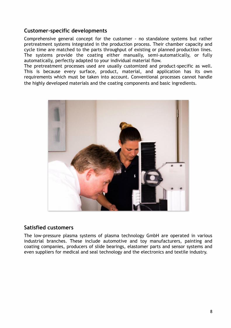
Customer-specific developments
Comprehensive general concept for the customer - no standalone systems but rather pretreatment systems integrated in the production process. Their chamber capacity and cycle time are matched to the parts throughput of existing or planned production lines. The systems provide the coating either manually, semi-automatically, or fully automatically, perfectly adapted to your individual material flow. The pretreatment processes used are usually customized and product-specific as well. This is because every surface, product, material, and application has its own requirements which must be taken into account. Conventional processes cannot handle
the highly developed materials and the coating components and basic ingredients.
Satisfied customers
The low-pressure plasma systems of plasma technology GmbH are operated in various industrial branches. These include automotive and toy manufacturers, painting and coating companies, producers of slide bearings, elastomer parts and sensor systems and even suppliers for medical and seal technology and the electronics and textile industry.
8

Coating services
plasma technology GmbH operates its own systems for process development to constantly optimize system and control technology and coating services. We use our existing system fleet to perform activations, structures, ultra-fine cleaning, and plasma-polymer coatings on nearly all material surfaces. Whether a small quantity, large quantity, bulk goods, staple goods or yard goods - the available options are highly diverse. Our coating-service offerings are suitable for companies who, due to small batch sizes, require a plasma treatment only temporarily or who want to bridge over the time until the start-up of their own system.
9

System construction
plasma technology GmbH offers not only customer-specific systems, but also a product line with laboratory and small systems. The chamber volume of these tabletop systems ranges from 2.4 to 32 liters. The machines of an additional product line are designed as standalone systems. They have chambers with volumes of 55, 100, and 150 liters. If small parts are to be processed as bulk goods in the aforementioned system types, the plasma chamber is equipped with a rotating basket to ensure all-round uniform treatment of all parts. When roll goods are treated, a push-in wagon is used to bring the winding into the chamber and rewind it in the plasma atmosphere during the treatment process. This product line generally has chambers with a size of several cubic meters. The size is determined by the winding length and its diameter. The capacity and vacuum-pump output are always adapted to the customer requirements for fully-automated systems, short-cycle systems, sliding-table systems, and large-scale systems. The largest low-pressure plasma system ever delivered by plasma technology has a diameter of 3 m and a length of 6 m, corresponding to a capacity of 42,000 Liter.
Seminars & training
plasma technology offers a practical plasma-technology day several times a year for persons interested in making plasma “tangible”. The requirements for adhesive strength and the system and process technology are explained in the theoretical part. The second, practical part is held at the system, with practical experiments being performed. It goes without saying that the plasma technology team offers intensive employee training for the operating personnel on the customer's premises as part of the system installation.
10

1 Introduction to plasma technology
A cold plasma is generated at a low pressure <100 Pa inside a vacuum chamber. The creation of electromagnetic fields causes the gases and gas mixtures contained in the chamber to ionize and thus be converted into the highly reactive plasma state. The surface properties of the components entering the chamber are selectively changed by the choice of the gas composition (air, nitrogen, oxygen, etc.) and the type of energy input [DC, kHz, MHz (radio frequency) or GHz (microwaves)].
In low-pressure plasma, surfaces can be
- ultra-finely cleaned,
- activated,
- coated,
- structured.
11

1.1 Plasma activation
Due to their unpolar character, many polymers cannot be printed on, painted or bonded, or only with great difficulty. Activation is therefore required to increase their surface energy. A low-pressure plasma process modifies the surface by functionalizing the polymer chains, e.g. using carbonyl (>C=O), Carboxyl (-COOH) or Hydroxyl groups (-OH). This increases the surface energy of the workpiece and adjusts the surface tension of the substance to be applied. These embedded functional groups can be characterized and quantified by electron spectroscopy for chemical analysis (ESCA).
1.2 Ultra-fine plasma cleaning
If extremely clean surfaces are required, they can be generated in the low-pressure plasma if the coating thickness of the contamination is thin. This process makes it possible to eliminate nearly all organic contaminants since these are converted to their gas phase in the plasma and removed by the constant gas flow.
1.3 Coating in the low-pressure plasma (plasma polymerization)
This process variation brings organic monomers of low molecular weight into a plasma as a process gas. These monomers are excited in the plasma. They are then split and precipitated into a strongly interlinked, permanent polymer coating on any desired substrate. The properties of this coating are determined by the type of monomer used, the auxiliary gas used and the selected process parameters.
1.4 Structuring of low-pressure plasma
The structuring selectively removes material from the surface and converts it to the gas phase so that it can be diverted out of the chamber. New process gas is continuously added to keep the conversion rate constant. The material removal roughens and enlarges the surface, making it wettable. This process variation makes it possible to pretreat polymers for a coating process which are difficult to paint and bond, such as POM, PPS or PTFE.
12

2 Examination of the pretreatment effects
The pretreatment of polymers by a plasma atmosphere can generally not be detected with the naked eye. Test inks solely indicate whether the wettability of the surface has changed. The following measuring opportunities for testing the effects achieved are available in our on-site technical center.
2.1 Contact-angle measuring device
As explained in detail in Section 3.4, the polar component generated by activation of a polymer surface determines whether or not the subsequent coating forms a strong bond with the surface. We therefore provide a contact-angle measuring device which can be used to determine the change in surface energy, particularly that of the polar component. The plasma parameters can be optimized based on the results achieved.
2.2 Tensile-testing machine
In contrast to painted surfaces, bonds with the original adhesive can be created nearly everywhere. The best indicator as to whether or not the activation has now produced the functional groups on the surface which are relevant for the adhesive is provided by the surface itself. We therefore offer a tensile-testing machine with a tensile force of up to 2.5 kN so that the test specimen can be bonded with the original adhesive following activation and its hardening tested.
2.3 Light microscope
This universal tool makes it possible to inspect the component surfaces before and after treatment to determine any change relating to the desired effect. Moreover, the fracture pattern of the adhesive bonds tested can be more meaningfully evaluated.
2.4 Friction-coefficient reduction
Section 3.5.4.4 includes a description of how to reduce the friction coefficient of elastomers by selectively precipitating the coatings in the plasma. However, the question of how well the achieved effect can be verified is also asked here again. A test device is provided for this which can be used to determine the improved gliding behavior and stability of the coating. The power required for one stroke can be determined on the one hand, while on the other hand, the number of strokes can be used to check if the precipitated layer withstands continuous loading and meets the required service life.
13

3 Plasma for pretreatment
3.1 The plasma
A material is in a solid state when all of its atoms, molecules, and ions have a defined place in the solid-material lattice interact with each other there. If an energy volume of > 0.4 eV is supplied to the system, the lattice structure dissolves and the material is converted to the liquid state. The fixed positions of the particles are now eliminated; clear interactions still exist between them however. An additional supply of energy (> 0.6 eV) results in the gaseous state. The particles now move freely and arbitrarily in the space. The frequency of their collisions depends on pressure and temperature. The additional supply of energy to this gas phase causes the particles themselves to be included in the process and excites them. The supply of an additional 4 eV raises individual electrons of the atom shell to higher orbits, i.e. higher energy levels. If the energy provided ranges from 4 – 18 eV, then the ionization range has been reached since electrons are knocked out of the outermost energy orbits and molecules are split. Along with ions, highly reactive radicals are now available for reactions with the surface of parts requiring pretreatment. Radicals are ions or molecules with an unpaired “lonely” electron in their outer orbit. The fourth aggregate state, also referred to as plasma, has now been achieved. It is comprised of neutral atoms and molecules, activated species, electrons, radicals and ions (Figure 1).
Figure 1: Composition of the plasma; the number of neutral molecules and/or atoms is much greater than could be represented in this diagram
The number of positive (ions) and negative charge carriers (electrons) is equal in plasma, thus making it neutral to the outside. However, the number of neutral species not affected by the supplied energy greatly predominates, generally leaving the degree of activation (sum of the activated species, radicals, and ions) in a range of just a few percentage points. The characteristic color required for a plasma state (Table 1) depends on the exited gas. Electrons emit light when they return from the exited state to their initial state. The energy difference between this initial state and the excited state determines the color of the light and is specific to the element or molecule.
14
Photons
Electrons
Activated species
Ions
Neutral atoms and molecules
Radicals
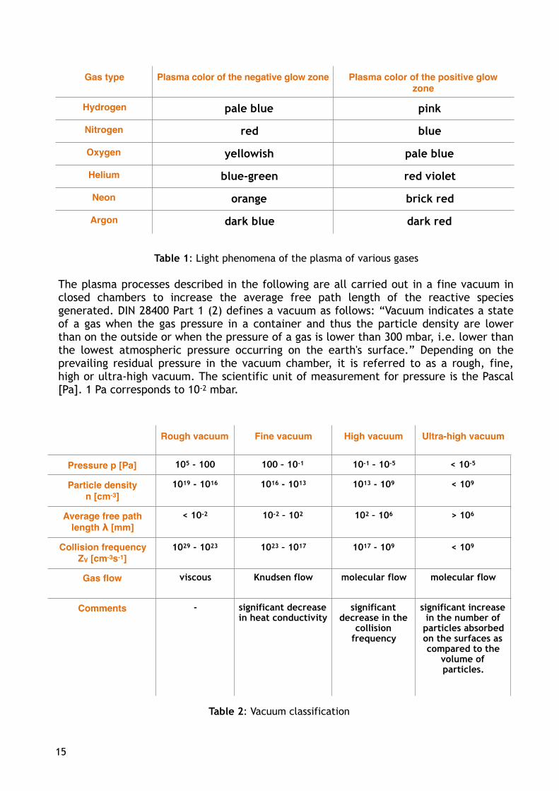
Table 1: Light phenomena of the plasma of various gases
The plasma processes described in the following are all carried out in a fine vacuum in closed chambers to increase the average free path length of the reactive species generated. DIN 28400 Part 1 (2) defines a vacuum as follows: “Vacuum indicates a state of a gas when the gas pressure in a container and thus the particle density are lower than on the outside or when the pressure of a gas is lower than 300 mbar, i.e. lower than the lowest atmospheric pressure occurring on the earth's surface.” Depending on the prevailing residual pressure in the vacuum chamber, it is referred to as a rough, fine, high or ultra-high vacuum. The scientific unit of measurement for pressure is the Pascal [Pa]. 1 Pa corresponds to 10-2 mbar.
Table 2: Vacuum classification
Gas type Plasma color of the negative glow zone Plasma color of the positive glow
zone
Hydrogen pale blue pink
Nitrogen red blue
Oxygen yellowish pale blue
Helium blue-green red violet
Neon orange brick red
Argon dark blue dark red
Rough vacuum Fine vacuum High vacuum Ultra-high vacuum
Pressure p [Pa] 105 - 100 100 – 10-1 10-1 – 10-5 < 10-5
Particle density
n [cm-3]
1019 - 1016 1016 - 1013 1013 - 109 < 109
Average free path
length λ [mm]
< 10-2 10-2 – 102 102 – 106 > 106
Collision frequency
ZV [cm-3s-1]
1029 - 1023 1023 – 1017 1017 - 109 < 109
Gas flow viscous Knudsen flow molecular flow molecular flow
Comments - significant decrease in heat conductivity
significant decrease in the
collision frequency
significant increase in the number of particles absorbed on the surfaces as compared to the
volume of particles.
15

3.2 Physical-chemical aspects
3.2.1 DC plasma
A direct-current high voltage (Direct Current DC) of around 10 kV applied to two electrodes melted down in a vacuum tube with a spacing of around 50 cm results in a glow discharge (Figure 2). A typical light phenomena can be observed within a pressure range of 103 Pa to 1 Pa, as has been used by glow-discharge lamps (operating pressure 100-3000 Pa) or fluorescent lamps (1-100 hPa operating pressure) for technical applications for many years already. This also involves a plasma; optimized, however, to the light intensity.
Figure 2: Regions in a DC glow discharge
The electrons escaping from the cathode are accelerated and ionize the atoms and molecules of the process gas in the negative glow zone. Impact ionization and recombination are used to emit gaseous light, which contains notable intensities in the vacuum UV. The electrons have a higher mobility than the heavy cations (positive ions), causing a positive space charge to form in front of the cathode. From here, cations with high energy (cathode falling potential) are accelerated to the cathode. When the cations are contacted, they atomize (sputter) the cathode material and also release electrons, which, on their part, sustain the glow-discharge process.
The number of positive ions is equal to the number of negative electrons in the positive column, making this column virtually field-free. A potential gradient (anode drop) also forms on the anode. The mass of the electrons is much too low, however, to atomize the anode material(1).
The DC glow discharge must only be maintained if sufficient electrons are generated from the cathode. This results in electrons being absolutely mandatory in the plasma.
16

3.2.2 Low-frequency/high-frequency plasma
For historical reasons, the frequencies 40 kHz (LF plasma) and 13.56 MHz (HF plasma) are used for technical applications. There was no radio traffic at these frequencies at that time. The EMC directives (Elektro-Magnetic-Compatibility) have meanwhile made all frequencies available, resulting in this parameter being used more and more.
The electrons can follow an electrical field generated at these frequencies and reach the electrodes or the wall of the reactor at every half-wave. Any electrons still colliding with the gas's molecules/atoms on their way to the anode are deflected, which has several consequences:
1 When sufficient energy is available, these electrons ionize the molecules/atoms and thus produce secondary electrons in the gas space.
2 The colliding electrons are deflected and thus no longer in phase with the alternating electric field. They absorb additional energy when they are forced back into phase by the electrical field.
3 A much smaller number of electrons reach a wall or the anode, where they are absorbed. They remain in the plasma and thus continue to be available for energy transfer to other species. LF/HF plasmas thus do not require any electrodes in the plasma.
The higher the frequency, the less the ions are able to follow the field due to their inert mass. The hydrogen ion, as the smallest ion, is around 2000 times heavier than an electron!
3.2.3 Microwave plasma
Here also, the 2.45 GHz frequency has a historical basis. Since the phenomenon referred to as the “skin effect” increases with increasing frequency, it is more advantageous to not use an electrode to integrate the microwave (MW) in the plasma. The MW field produced by a magnetron is induced into the plasma chamber by a window which is usually constructed of quartz glass or aluminum oxide.
The wave length of around 130 mm is within the dimensional range of the plasma chamber. This results in the electrons no longer reaching the chamber wall when the field reverses, whereby the number of electrons in the plasma greatly increases. The charge density becomes so high that the plasma reflects the microwave. The microwave plasma is thus very dense on the one hand and supplies a large number of reactive species, while on the other hand, it is volumetrically highly inhomogeneous and limited to the area around the connecting window. The reactive species diffuse from the plasma zone and react with the surface of the substrate to be treated. The plasma itself is very hot; therefore the substrate must be stored outside of the plasma zone if it is sensitive to temperature.
17

3.2.4 Process gases
The process gas used is crucial for the success of a plasma treatment (Table 3). Oxygen or air is used to activate polymers and to gently clean surfaces, while hydrogen diluted with argon or helium is used to reduce oxides. Fluorine gases are used in semi-conductor technology and plasma polymerization. Metal surfaces and Teflon can be reduced or activated by hydrogen plasmas. With this application, the main component of the supplied reaction gas is argon, whereby safety aspects which must be complied with due to the reactivity of the hydrogen are taken into account.
Table 3: Industrially-used gases for low-pressure plasma processes
Process Possible process gases Preferred excitation frequency
Glow-nitriding/ion-nitriding, plasmanitriding
N2/H2, NH3, Ar DC
Plasma cleaning/activation, Plasma etching (general)
CF4, O2, Cl2, Ar, air LF, HF, MW
Ion Etching (IE), Plasma Etching (PE), Reactive Ion Etching (RIE)
CF4, O2, N2, Ar, He DC, HF
Borehole cleaning (“Desmearing”) O2, CF4 LF, HF, MW
Ion etching before coating in the vacuum
O2, Ar, H2 LF, HF
Surface activation of polymers Air, O2 LF, HF, MW
Surface activation of PTFE NH3, N2, H2, Ar, O2 LF, HF, MW
Ultra-fine surface cleaning Air, O2, H2, CF4 LF, HF, MW
18

3.3 Plasma sources and system technology
The selection of the excitation frequency depends on the application. Primarily DC is used for plasma nitriding, with the (electrically conductive) parts acting as a cathode. LF/HF or MW plasmas are used for plasma activation, plasma cleaning, and plasma coating. LF and MW plasma systems are easier to handle in everyday operations. This is because the requirement and adaptation of the generators is not as critical as with HF excitation.
The wall of the vacuum chamber usually acts as an anode and is at ground potential. The electrode is capacitively coupled and the LF/HF electrode connected to the high-frequency source (Figure 3). The matching network prevents this electrode (cathode) from being DC-grounded, enabling a DC voltage to possibly develop there (capacitance in series with the generator and ground).
Figure 3: Capacitively coupled LF/HF plasma system,with the chamber wall acting as an anode
The surface ratio between the anode and cathode has a considerable impact on the electrical potentials. Due to the higher mobility of the electrons and thus the higher probability of their hitting the wall, plasma is always at a positive potential with respect to the wall (ground) and cathode. This plasma potential VP oscillates with the potential of the energizing field Vrf. The zero line of the cathode potential Vk takes on an increasingly negative value as it becomes smaller and in turn, becomes more and more positive as the surface area increases with respect to the anode. The potential VK thus does not oscillate around the zero-volt potential, but rather around a DC Potential VDC which has been shifted up or down and is also referred to as the “self bias”. This must be taken into account to avoid undesired sputter effects on the cathode.
19

An essential differentiating factor of plasmas is their excitation frequency. The following frequency ranges are differentiated with their properties:
Table 4: Plasmas and their properties
In the LF range, it is possible for both the light-weight electrons and the heavy gas ions to follow the oscillating alternating field. This results in the effects of the ion bombardment on the LF electrode and the grounded chamber wall as described above. This excitation frequency also causes a relatively homogeneous plasma to form in large chambers as well, enabling the complete surface of complexly shaped plastic molded parts, for example, to be fully treated.
The heavy ions can no longer follow the alternating field in the HF range. They follow the potential VDC generated by the self-bias against the backdrop of the plasma potential VP, which is diffuse for them. High-frequency plasmas enable a precisely defined ion bombardment of average energy.
The storage of the substrate in the planar reactor (plate or parallel reactor) also has a major impact on the effect of the treatment. The following designs apply for the capacitive coupling of the excitation frequencies 40 kHz and 13.56 MHz.
DC LF HF MW
Frequency 0 40 kHz 13.56 MHz 2.45 GHz
Energy coupling Electrodes capacitive, inductive
capacitive, inductive
direct waveguide
Degree of ionization
Operating pressure > 1 Pa > 1 Pa 10-1 Pa 102 Pa
Excitation electrode
in the chamberyes usually
inside / also outside
usually inside / also outside
-
Ion bombardment of
the electrodevery high very large lower not
present
Uniformity of the
plasma across the
chamber volume
very good very good good not as good
Costs inexpensive inexpensive expensive average
20

Figure 4: Mounting the substrate on the cathode
The substrate rests directly against the cathode and takes on its potential. This is advantageous when the anode (= grounded electrode) is larger than the cathode. If this ratio increases, then the negative “self bias” also increases on the cathode. This causes the positively charged ions in the DC field to be accelerated to the substrate, which then sputters. The effect is purely mechanical if a noble gas is used as a process gas. The use of other gases, e.g. those containing oxygen, results in additional chemical reactions on the surface. An anisotropic chemical reaction is thus superimposed on the isotropic, physical components. This reaction control is referred to as Reactive Ion Etching RIE. Suitable reaction control makes it possible to produce structures without undercutting. The substrate must meet two conditions for this process - it must be stable in heat and electrically conductive.
Figure 5: Mounting the substrate on the anode
21
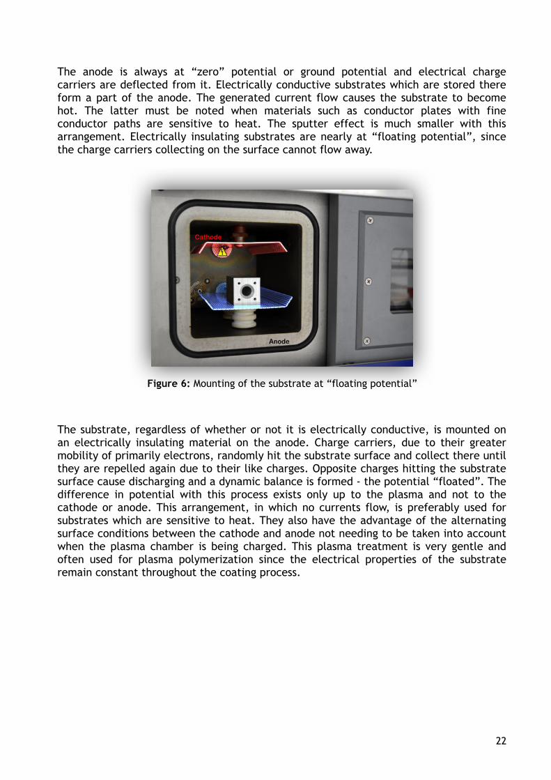
The anode is always at “zero” potential or ground potential and electrical charge carriers are deflected from it. Electrically conductive substrates which are stored there form a part of the anode. The generated current flow causes the substrate to become hot. The latter must be noted when materials such as conductor plates with fine conductor paths are sensitive to heat. The sputter effect is much smaller with this arrangement. Electrically insulating substrates are nearly at “floating potential”, since the charge carriers collecting on the surface cannot flow away.
Figure 6: Mounting of the substrate at “floating potential”
The substrate, regardless of whether or not it is electrically conductive, is mounted on an electrically insulating material on the anode. Charge carriers, due to their greater mobility of primarily electrons, randomly hit the substrate surface and collect there until they are repelled again due to their like charges. Opposite charges hitting the substrate surface cause discharging and a dynamic balance is formed - the potential “floated”. The difference in potential with this process exists only up to the plasma and not to the cathode or anode. This arrangement, in which no currents flow, is preferably used for substrates which are sensitive to heat. They also have the advantage of the alternating surface conditions between the cathode and anode not needing to be taken into account when the plasma chamber is being charged. This plasma treatment is very gentle and often used for plasma polymerization since the electrical properties of the substrate remain constant throughout the coating process.
22

The energy is inductively coupled in a barrel reactor (tunnel or tube reactor) at 40 kHz or 13.56 MHz. The reactor-wall material must be electrically insulating, e.g. made of quartz or aluminum oxide. The plasma is generated by an electric field inside of the coil which is located outside of the chamber.
Figure 7: Inductive energy coupling
In this case, the geometry of the reactor is primarily determined by the mechanical and physical properties of the ceramic materials used for this. This type of plasma generation is preferably used when doping effects on the substrate need to be avoided. When the previously described reactors with metallic chamber walls are used, they and primarily the cathode are sputtered. Some of the removed metal ions collect on the substrate in the continuing process. Such doping does not occur when ceramic chamber walls are used.
Figure 8: Microwave reactor with waveguide = downstream reactor
23

The microwave plasma gathers around the coupling window and is therefore heterogeneoususly distributed in the chamber. A standing wave is generated in the waveguide (= Magnetron with “horn radiator”); this is decoupled by the quartz window in the reactor. The gas ionization by the microwave is so effective that the plasma forms a Farady cage and is largely shielded by the volume of the reactor. Nevertheless, a large number of highly excited molecules diffuse from the plasma and they interact with the surface of the substrate.
Figure 9: Remote setup of a microwave reactor
In the case of a remote setup, the plasma burns in a separate plasma chamber, from where the highly reactive species is routed to the actual reaction chamber. The success of this technology requires a high number of reactive species to be generated in the plasma; this will ensure they are sufficient in number for the reaction despite the long path to the substrate surface. Collisions with each other and with non-active species or absorption on the walls decrease the number of active species considerably. For this reason, microwave excitation is the most suitable frequency for this structure, as it produces a particularly large quantity of excited species.
The remote technology offers more degrees of freedom in the reaction control. Any process gases used can be routed through the process source or fed directly into the treatment chamber. This brings advantages for the polymerization process as a reactive gas such as oxygen or hydrogen can be routed through the plasma source in this process and the monomer gas, for example propane, is directly routed into the treatment chamber. This means that the monomer gas is not exposed to the high energy density of the plasma, but rather solely interacts with the excited species of the reactive gas. The option of supplying the process gas in various ways provides a genuine chemical construction kit for setting new coating properties on the substrate.
24
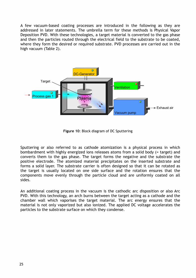
A few vacuum-based coating processes are introduced in the following as they are addressed in later statements. The umbrella term for these methods is Physical Vapor Deposition PVD. With these technologies, a target material is converted to the gas phase and then the particles routed through the electrical field to the substrate to be coated, where they form the desired or required substrate. PVD processes are carried out in the high vacuum (Table 2).
Figure 10: Block diagram of DC Sputtering
Sputtering or also referred to as cathode atomization is a physical process in which bombardment with highly energized ions releases atoms from a solid body (= target) and converts them to the gas phase. The target forms the negative and the substrate the positive electrode. The atomized material precipitates on the inserted substrate and forms a solid layer. The substrate carrier is often designed so that it can be rotated as the target is usually located on one side surface and the rotation ensures that the components move evenly through the particle cloud and are uniformly coated on all sides.
An additional coating process in the vacuum is the cathodic arc disposition or also Arc PVD. With this technology, an arch burns between the target acting as a cathode and the chamber wall which vaporises the target material. The arc energy ensures that the material is not only vaporized but also ionized. The applied DC voltage accelerates the particles to the substrate surface on which they condense.
25

Figure 11: Block-Diagram of DC of a PECVD
PECVD (Plasma Enhanced Chemical Vapor Deposition) is a special form of Chemical Vapor Disposition (CVD), which uses a plasma to enhance the chemical vapor disposition. The plasma used can be directly generated in the same chamber as the substrate (direct plasma) or produced in a separate chamber (remote plasma). The plasma's accelerated electrons facilitate the breakup of the reaction-gas molecules. The generated radicals and ions jointly cause the coating to deposit on the substrate. The heat input by the plasma to the surface is low, allowing temperature-sensitive materials to also be coated.
An electrical field is generated between the substrate to be coated and the opposing electrode; the plasma is ignited by this field (direct-plasma method). The remote technology has the advantages and drawbacks already mentioned, also with PECVD.
The vacuum pumps required for the plasma process are individually selected independently of the required vacuum pressure and the process to be implemented. Rotary vane pumps are generally used for standard cleaning and activation processes. These oil-lubricated pumps are less expensive to purchase than dry-running vacuum pumps. The operating range of both pump types reaches from atmospheric pressure to fine vacuum. A roots pump is also connected if the desired vacuum pressure needs to be generated quickly, even for large chamber volumes. A turbo-molecular pump is used instead of the roots pump if the process requires a high vacuum such as for a PVD or ALD coating, Dry-running vacuum pumps are always used if contamination by oil must be avoided in all circumstances. Dry runners generally require lower maintenance and also have high endurance even for “hard” processes. The operating chamber of this pump type is produced from resistant metal which doesn't react with the media and is thus fully excluded from cross-contamination. The following overview lists possible pump combinations.
26

Table 5: Overview of the vacuum pumps used for pretreatment processes
27

3.4 The substrate surface
The required, but not adequate, condition for achieving good adhesion strength is adequate wettability by the coating substance. The adhesion strength is a scale for the resistance of the coating to its mechanical separation from the substrate.
A variable for the wettability of a substrate surface by a fluid - paint, glue, etc. - is the contact angle Θ between the solid body and an applied droplet. The wettability improves as the contact angle Θ decreases. The surface tension of the fluid and the surface energy of the substrate are decisive for the contact angle.
The Young equation describes this relationship:
Figure 12: Contact angle
Substrate with higher surface energy (metals) can be more easily wetted than those with lower surface energy (polymers). The reason for this is the material structure and the fact that the wetting lowers the total system energy by reducing the boundary surface (solid) with respect to the surrounding air (gas) When the fluid wets the substrate, this condition is referred to as spreading. In this case, the contact angle Θ approaches zero and cosΘ approaches 1; this means that the energy of the surface to be wetted is high and the requirements for wetting fulfilled.
The contract angle Θ is precisely determined by a contact angle measurement, in which various fluids with known surface tension are deposited on the material surface and measured.
28

The determined surface tension/energy is comprised of a polar γp and a disperse γd fraction.
γ = γp + γd
The polar fraction is the sum of various types of molecular forces such as induced dipoles, van-der-Waals forces and hydrogen bonds. The substrate to be coated must have a polar fraction similar to the lacquer or adhesive to enable formation of intermolecular forces of the substrate and coating material. Only then can wetting and adequate adhesion strength be achieved.
In daily practice, test inks are used to determine the surface energy of workpiece surfaces. These are standardized test fluids which are applied to the surface by a brush or cotton swab. A visual assessment of whether or not the fluid wets the surface can be made within 2 seconds. If the ink film contracts, then the surface tension of the ink is greater than the surface tension of the substrate. In this case, inks of smaller surface tension are further tested until an ink wets the substrate for at least 2 seconds. The surface energy of the material becomes known when this condition is achieved. Inks with higher surface tensions are also used if the first fluid applied wets the surface. In this case, the test is repeated until the film contracts again. The last ink to just barely wet the surface provides the surface-energy value of the substrate.
The test inks can be used to determine the total energy. A division into polar and disperse fractions cannot be made with this process. Moreover, they provide just one indicator of the wettability. No conclusion about the adhesion strength of the coating is possible.
The test inks are offered in different series by various manufacturers on the market. Make certain if comparative measurements are to be made by the customer and supplier or within the company that inks of the identical manufacturer and series are used.
29
3.5 Applications of plasma technology
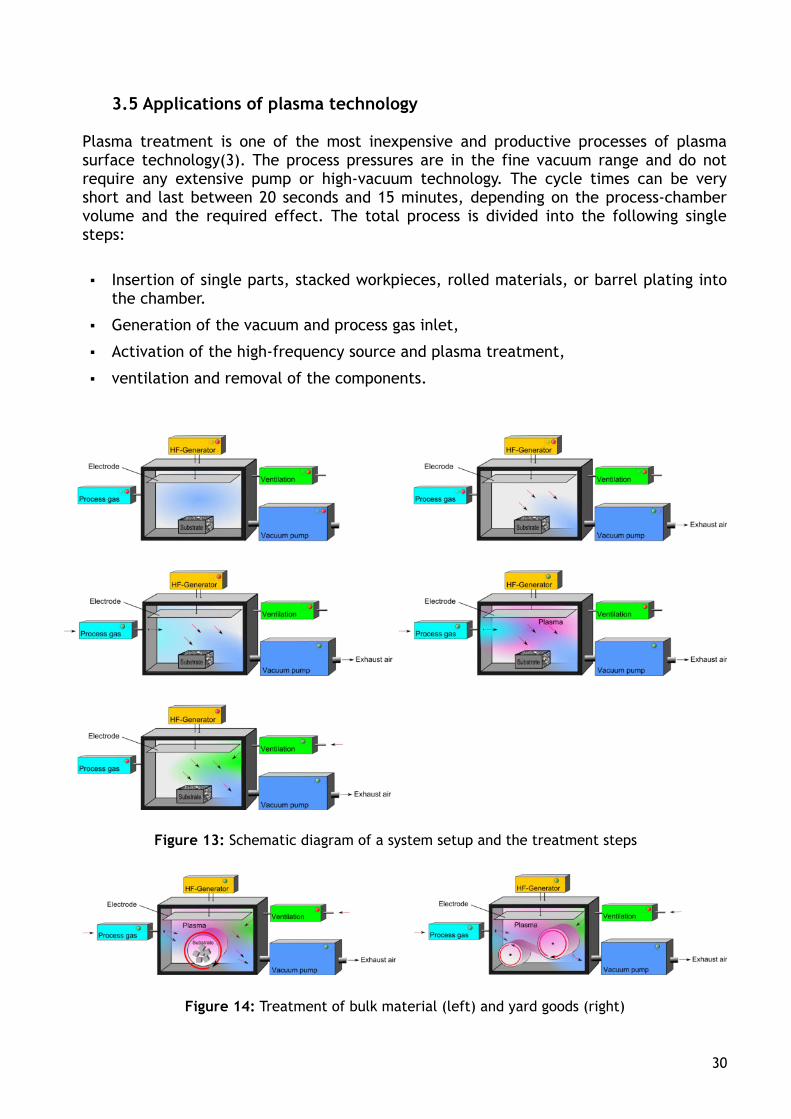
Plasma treatment is one of the most inexpensive and productive processes of plasma surface technology(3). The process pressures are in the fine vacuum range and do not require any extensive pump or high-vacuum technology. The cycle times can be very short and last between 20 seconds and 15 minutes, depending on the process-chamber volume and the required effect. The total process is divided into the following single steps:
▪ Insertion of single parts, stacked workpieces, rolled materials, or barrel plating into the chamber.
▪ Generation of the vacuum and process gas inlet,
▪ Activation of the high-frequency source and plasma treatment,
▪ ventilation and removal of the components.
Figure 13: Schematic diagram of a system setup and the treatment steps
Figure 14: Treatment of bulk material (left) and yard goods (right)
30

3.5.1 Ultra-fine cleaning of surfaces with the aid of plasma
Production, storage and transport causes all surfaces (glass, ceramic, metal, plastic) to more or less become coated with undefined contaminants, which must be cleaned off before a coating process can be carried out. Several cleaning steps are required, depending on the degree and type of contamination and the chemical composition. The surfaces first undergo a coarse cleaning process. Even when they appear clean and dry to the naked eye, they are still coated with a natural adhesive layer of organic compounds and water, which can be cleaned off in a plasma atmosphere.
Ultra-fine plasma cleaning is particularly suited for the removal of thin organic contamination films such as silicons, waxes, oils, etc., which act as a separating layer and can negatively impact the adhesion strength of the following coatings or joining processes. The reaction products typically formed are CO2 and H2O and since both are highly volatile gases under vacuum conditions, they are removed from the vacuum chamber together with the continuous working-gas flow.
The plasma's effective cleaning impact is demonstrated below on a sooted glass panel. The panel was placed in the vacuum chamber and after 120 seconds, the oxygen plasma oxidized the soot and the surface was cleaned with no residues.
Figure 15: top left: masked glass panel following sooting; View of the plasma chamber during the glass-panel cleaning in low-pressure plasma; top right: Start, lower left: after 60 seconds, lower right – cleaned glass surface after 120 seconds (specified times apply
for this cleaning)
31

It must be expressly emphasized, however, that plasma cleaning is only suited for the removal of the thinnest surface contaminants (layer thickness in the nanometer range). Thicker organic residues can form a resin under the influence of oxygen, particle bombardment, and UV radiation or react with the surface to form oxidation products. Such crack products or oxidation residues can often no longer be removed, even under the hardest reaction conditions.
3.5.1.1 Ultra-fine cleaning of metals
The ultra-fine plasma cleaning of metal surfaces was (4) investigated in a joint industrial project. The result of the experiments was that the cleaning effect, measured by the total carbon content on the surface, of solvents with and without halogen and also of watery cleansers could be further improved upon by a subsequent plasma treatment.
The impact of the specimen temperature and the type of oil on the removal rate of natural and mineral oils treated with plasma was investigated in an additional research project. (5) When mineral oils are used, the removal rate decreases with increasing viscosity. When natural oils with unsaturated fatty acids are used, the removal rate decreases as the fraction of double compounds increases due to a resin forming in the oxygen plasma. A considerable removal effect is already achieved by the evaporation in the vacuum. A high specimen temperature causes a high removal rate, even without oxygen plasma.
Figure 14 shows a metallic workpiece coated with soot in plasma. At the start of the cleaning process, the color of the plasma is pale purple and then glows a yellowish green at the end of the process when no more soot molecules are being removed and converted to the gas phase.
Figure 16: intentionally sooted metal part during a cleaning process in the plasma chamber
Not only the change in the plasma color indicates that the soot layer has actually been removed; it can also be verified by measurement. This is possible when a spectroscopic plasma monitoring system is integrated in the system. The characteristic light appearance released during the plasma process is a mixture of many separate light emissions which are specific for the elements. This means that every element or molecule emits light of a characteristic wavelength. A light-wave conductor detects the various wave lengths in-situ and transmits them to the spectroscope. The type of the existing gas molecules is recorded
32
Soot

there and the signal strength can be used to make a conclusion about their quantity. The spectrum obtained in this manner can be viewed on the PC at every point in the plasma process.
The emission signals of the carbon compounds forming during plasma cleaning are considered in the following. At the start of the process, the concentration in the chamber is high because the cleaning process is just starting (spectrum 1); this means the lines can be clearly detected at 289 nm and 655 nm. Their height decreases as the process progresses. This is because the contamination is converted and removed. Once the organic layer is decomposed, the carbon-compound signals deteriorate into “background noise”, the surface is cleaned (spectrum 2), and the process ended. The signals of the excited oxygen at 558 nm and 777 nm are much more pronounced than at the start of the process. This is justified by the fact that no more contamination molecules are available to react with the added oxygen(6).
Spectrum 1: Emissions spectrum at the start of the process
Spectrum 2: Emissions spectrum at the end of the process
33

This spectral analysis is provides a real-time observation of the light emissions in the chamber and thus the process control. Spectroscopic monitoring enables the stability of every single process to be analyzed. This spectral analysis can be used to determine the end point of any etching processes carried out in the low-pressure plasma. The real-time measurement of the plasma atmosphere enables the conversion rate to be kept constant by readjustment of the gas flow during reactive plasma sputter processes. The spectroscopic plasma analysis is also used for the quality control of the individual runs by monitoring sensitive processes in-line and possibly readjusting and optimizing them.
Reducing plasmas can further be used to remove oxide coatings from metals.
Figure 17: shows a 2-cent coin, which was masked on one side during the plasma treatment.
Micro-organisms can be “sputtered off” of any material surfaces in a plasma atmosphere, generating ultra-clean surfaces. It has already been scientifically proven that ion bombardment can be used to remove adsorbates and other interfering coatings on an atomic scale (7). Several mechanisms are at work during this special cleaning process (8):
▪ the applied “fine” vacuum and the temperature increase when the organisms make contact with the highly energized plasma species dry them out;
▪ the oxides contained in the plasma atmosphere and the resulting UV radiation kills the bacteria.
▪ the low pressure increases the free wave length of the reactive species, causing them to hit the surface with high kinetic energy and convert contaminants to the gas phase, which is removed from the chamber by the constant gas transport.
The chamber must be ventilated exclusively with nitrogen following the “sterilization process” in order to prevent new contamination by the ambient air.
34
following plasma
before plasma treatment

3.5.1.2 Ultra-fine cleaning of polymers
Polymer materials primarily contain various additives to make processing easier and to achieve the properties of the final product. Internal separating agents, flow additives, anti-static agents, anti-aging agents, and UV stabilizers are frequently used, for example. All substances which develop their properties on the component surface more or less form a closed layer. This film acts as a separating layer and generally prevents good adhesion strength of the applied coating or adhesive. In order to still meet the required test specifications, components are laboriously cleaned with solvents and must then be dried. The removal of such residues or contaminants in a plasma atmosphere has the particular advantage of involving a dry chemical process. In contrast to a wet chemical process, no residues of any kind from the cleansers used can deposit on the workpiece surface.
Figure 18: Principle of plasma cleaning
Organic compounds are split in the plasma, converted to the gas phase and removed from the chamber primarily as CO2 and H2O. Lubricants and fatty acids are also removed, as are anti-oxidants and components of low molecular weight; this eliminates their anti-adhesive effect and leaves a clean surface for the coating to anchor on. The applied vacuum pressure has the additional charm of making the plasma's reactive species cover the workpiece's complete surface uniformly, even if it is small, highly structured, or complex.
3.5.1.3 Freedom of substances hindering the wetting properties of coatings
Good wetting by lacquer or adhesive is only achieved on clean, dry, oil-free and silicon-free workpiece surfaces. The lack of silicon on the surfaces is also particularly important when they are used in products needed to meet the criterion of containing no substances which hinder the wetting properties of coatings. The “silicon-free” component property is frequently not sufficient for the usage of such items as sealing rings in medical technology or compressed-air application in highly automated painting technologies. The components used in such applications must be free from all substances hindering the
35

wetting properties of coatings to rule out any defects or contaminants in, on, or caused by the final product.
There are numerous causes for the contamination of components with substances containing silicon. These can include internal and external separating agents for easier deformation of injection-molded parts, vulcanized components, or lubricants for the extrusion of elastomer profiles. Pigments and fillers are also treated with emulsions containing silicon to achieve better dispersion in the polymer matrix. The components can also become contaminated in the production process by lubricants of moving tool parts or hoses. Insufficient care when cleaning ceiling and floor filters or the water separation in painting cabinets can cause scratches in the applied lacquer coat which are often caused by silicon residues of unknown origin. Improper packaging of components containing no substances hindering the wetting properties of coatings predestines them to become contaminated again. As a rule, the person handling the parts is unknowingly a “contamination source” due to impregnated clothing, the wearing of rubber gloves, and the use of cosmetics, hand creams, hair-care products or perfumes (9).
Not all of these possible causes can be excluded along the production chain. For this reason, the parts require customized cleaning to meet the required criterion of freedom from all substances hindering the wetting properties of coatings. An easy option is cleaning with solvents. It cannot, however, be favored from an occupational-health aspect and under consideration of the current VOC directive. Low-pressure plasma is an alternative cleaning process in this case as well (Figure 19).
Figure 19: Sealing rings during the cleaning process in a rotating plasma chamber
36

The interplay of UV radiation, coordinated process gas, gas input, and extraction ensures that substances containing silicon are converted to volatile and non-volatile components and removed. The process time for the surface cleaning depends on the degree of contamination. The cleaning of parts in plasma is a dry process, i.e. no reaction products form which remain on the surface as residues or must be disposed of as waste. The process control is designed in a way that no substances of any kind containing silicon remain in the chamber. Extreme care must be guaranteed for the subsequent parts handling. Care must be taken to ensure that the person removing the parts from the chamber wears gloves free of all substances hindering the wetting properties of coatings. The process sequence is optimally designed when the plasma system acts as an air-lock between the production area and the assembly or coating area which is free of substances hindering the wetting properties of coatings. The system is then designed with two doors which can only be opened alternatively - loading on the production side, cleaning step, enabling of the door on the assembly side, parts removal. Closing the door enables the system to be equipped again. This rules out the chance of any silicon particles getting into the chamber.
Figure 20: Standalone plasma system which can act as an air-lock
37

3.5.1.4 Cleaning of particulate contamination
Polymer components become strongly electrically charged during transport from the production area to the coating area. This is due to friction on the packaging or to the removal from plastic bags. The formation of these static-charge pockets cause dust particles to collect on the workpiece surface, which lead to defects in the coating. The plasma process is also an excellent option for eliminating static charge and removing particles from the components. The positively charged ions in the plasma not only activate the surface but also neutralize the component's electro-static charge. A measurement of the field strength before and after the process would indicate its reduction from a good several kilovolts per meter (Figure 21, left) to nearly zero (Figure 21, right). The discharging process releases the dust particles and enables their easy removal(10), (11).
Figure 21:Electro-statically charged component before the plasma process (top) and in its discharged state following the plasma process (bottom)
38

Figure 22: Mobile extraction system designed for removing dust from polymer components
The charged components are placed on the grid and the hood is closed. The process begins when the cover contacts the base plate. The chamber is evacuated, the plasma acts on the component, and special air control ensures that the loose particles are removed from the surface when the chamber is ventilated. Following a cycle time of just 40 seconds, this application provides a dust-free, activated component for the coating process.
3.5.2 Activation of polymer surfaces
Fluids behave differently on solid substrates. Water rolls off of greasy or non-polar substrates, while, in contrast, it forms a closed film on a clean, grease-free metal surface. Water-repellent (=hydrophobic) materials include all greases, waxes and especially plastics, from which countless piece goods are currently being produced. Not even solvent-based coating materials spread on non-polar plastics as there are no functional groups there which they can interact with. If the adhesive or paint already rolls off of the substrate in the liquid state, then no adhesive strength can be expected for the dried adhesive or paint either. Good surface wetting, however, is still no guarantee for good anchoring of the coating material.
The wettability is physically described by the fluid's surface tension and the surface energy of the substrate. Both must be at a similar level for wetting to be possible(12).
39

Figure 23: Polyolefin surface still not wettable in the middle due to masking; the drops of fluid remain “sitting”; left and right corners activated and the fluid wets the surface
The polyolefins have a surface energy of around 30 mN/m and the polar component is nearly zero, requiring it to be activated before a coating process. Since the surface energy of printing inks is around 38 mN/m, that of adhesives and water-based inks of 44 mN/m is somewhat higher. The topmost molecule layers of the polymer surface can be modified by an air or oxygen plasma. The energetic species on the surface causes bonds to break and thus generates reactive spots. Following treatment, polyolefin surfaces contain carbonyl (>C=O), carboxyl (-COOH), hydroxyl (-OH) and other functional groups with oxygen which are now available to bond with the coating material. The use of process gases containing nitrogen such as N2 or NH3 enables additional functional groups containing nitrogen to be added which result in improved adhesion strength.
The components are placed in the plasma chamber as bulk goods, stacked goods, or directly on the coating mounts. The throughput of the coating process is adapted to the size of the chamber and the performance of the vacuum pump. Fully automated low-pressure plasma systems which are synchronized with the the coating-line cycle are meanwhile being used on the market(13).
40

Figure 24: Design of a fully automated low-pressure plasma system
Table 6: Technical details of a system in operation (14)
The equipped trays in the system shown in Figure 24 are fed from the right to the base plate under the plasma hood which forms the walls and ceiling of the vacuum chamber. The hood moves automatically downwards and the process starts as soon as it rests on the base plate. The parts remain in the highly energetic plasma atmosphere for just 5 seconds. This short time is sufficient to add functional groups to the polymer chains and to thus bring the surface energy to a uniform level. The chamber is then ventilated, the hood rises, and the trays are transferred to the coating-line conveyor belt. Just 30 seconds pass between the time the pretreatment unit enters and exits the chamber(14).
Chamber volume 190 liters
Effective volume = component volume 150 liters
Treatment cycle 30 seconds
Volume of activated parts/hour approx. 18 m³
Volume of activated parts/24h approx. 430 m³
Connected power approx. 20 kW
Process gas Air
41
Trays

A similar system concept is used to activate flat interior components, providing the laminated decorative layer with adequate adhesion strength.
Figure 25: Design of an automated low-pressure plasma system with sliding table
The extendable sliding table offers the advantage of easy placement and removal of large, flexible components or sealing frames.
Small housings, connectors, capacitor cans and other components are activated in a mini-plasma system, which is integrated in the rotary table, before they are molded.
Figure 26: Short-cycle mini-plasma system with around 400 cm³ chamber volume integrated in the rotary indexing table
This is also a short-cycle system, which requires around 20 seconds for evacuation, plasma and ventilation. The component mount could be modified to also serve as the vacuum-chamber floor.
42
3.5.3 Structuring of plastic surfaces
With a selective plasma treatment, referred to as plasma structuring or plasma etching, corresponding process control and gases can be used to treat surfaces in a way that makes them highly wettable. These processes selectively remove material from the surface, convert it to the gas phase, and continuously pump it out.
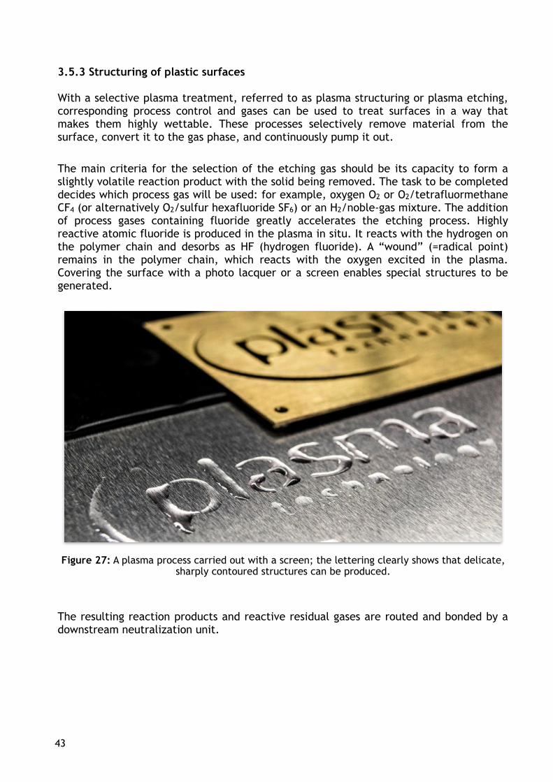
The main criteria for the selection of the etching gas should be its capacity to form a slightly volatile reaction product with the solid being removed. The task to be completed decides which process gas will be used: for example, oxygen O2 or O2/tetrafluormethane CF4 (or alternatively O2/sulfur hexafluoride SF6) or an H2/noble-gas mixture. The addition of process gases containing fluoride greatly accelerates the etching process. Highly reactive atomic fluoride is produced in the plasma in situ. It reacts with the hydrogen on the polymer chain and desorbs as HF (hydrogen fluoride). A “wound” (=radical point) remains in the polymer chain, which reacts with the oxygen excited in the plasma. Covering the surface with a photo lacquer or a screen enables special structures to be generated.
Figure 27: A plasma process carried out with a screen; the lettering clearly shows that delicate, sharply contoured structures can be produced.
The resulting reaction products and reactive residual gases are routed and bonded by a downstream neutralization unit.
43

3.5.3.1 High-performance plastics
It is not possible to directly coat or bond Polyoxymethylene POM and Polytetrafluorideethylene PTFE (=Teflon).
-CH2-CH2- -CF2-CF2- -CH2-O-CH2-O- Polyethylene Polytetrafluoroethylene Polyoxymethylene
PTFE is much more inert than its related polyethylene. The fluoride atoms are larger than the hydrogen atoms. They surround the carbon chain of the macromolecule like a protective sleeve. The carbon bond is so strong that it can barely be dissolved. This results in high resistance to chemical corrosion and high physical and chemical resistance in heat. The high bonding energy between carbon and fluoride and the low polarization capacity of the fluoride atoms result in it having much smaller inter-molecular forces than other polymers. This is the basis of the anti-adhesive behavior (15). PTFE is activated by H2/noble-gas mixtures, N2 or NH3. Only activation is possible for highly compact materials.
POM is linearly constructed like polyethylene and polytetrafluoroethylene. In contrast to PE (approx. 30 mN/m // 0.1 mN/m) and PTFE (approx. 19 mN/m // 0.5 mN/m) it has the highest surface energy at approx. 42 mN/m and a polar fraction of around 6 mN/m. It is therefore reasonable to conclude that POM can be well coated. Nevertheless, the adhesion strength of paints and glues is unsatisfactory. Brief activation in an O2 plasma greatly improves the result. Its molecular structure, however, makes it highly resistant to solvents, preventing lacquers and adhesives from anchoring. PTFE and POM can be modified – structured and activated – by plasma treatment under highly reactive conditions to the extent that they can be coated and bonded.
Figure 28: REM mounts of PTFE (top) and POM (bottom) before (left) and after (right) their structuring in plasma.
44

Figure 29 schematically shows that the PTFE surface is not only structured, but also modified, with the fluoride atoms being substituted by hydrogen atoms and forming dipoles which enable interaction with the coating material.
Figure 29: Modified PTFE surface
3.5.3.2 PCB etching (16)
Printed Circuit Boards PCB are the base supports for electronic components which are mechanically attached and electronically contacted there. The circuit board consists of electrically insulating material, usually a fiberglass-reinforced epoxy resin matrix, to which the copper conductor tracks are attached. Multi-layer circuit boards are meanwhile being used to increase the packing density. These layers are selected in accordance with the circuit board's purpose and can consist of Prepreg (preimpragnated fibers), FR4 (flame-resistant, fiberglass-reinforced epoxy resin matrix), polyimide foil (PI) and Teflon.
Figure 30: Schematic diagram of differently constructed multi-layer circuit boards (top structure: rigid; bottom: rigid-flex; polyimide is the base material for the flexible component)
45
Fluoride
Hydrogen
Carbon
FR4

The various levels in the circuit board are drilled mechanically or with laser to enable them to be electrically connected. The heat input during drilling can cause melted resin particles to collect on the wall of the drilled hole or on the inner layers, while with laser-drilling, the laser debris precipitates on the surface. In both cases, these (smear) layers must be removed to ensure interlayer contacting. The borehole cleaning is also referred to as “desmear” or “desmearing”.
Figure 31: “Defects” on the multi-layer circuit boards caused by mechanical processing
Several processes for wet-chemical borehole cleaning have been around for years. The use of the chemicals previously used is no longer possible or only conditionally possible due to the REACH Regulation. The chemicals used include sulphuric acid, which is only suitable for FR4, and permanganate for FR4 and polyimide. PTFE is activated with a sodium-naphthalene emulsion, which is highly flammable in connection with water. Chromo-sulphuric acid is no longer permitted for use. An additional drawback of wet-chemical borehole cleaning is the swelling of the resin; in the case of polyimide, glasswort must even be additionally added to the bath so that it can be (economically) etched. The swollen resin, however, doesn't usually return to its original dimension, not even when it is tempered. The increasingly finer structures and unfavorable diameter-length ratios (= aspect ratio) thus place restrictions on wet cleaning. Two completely self-sufficient processing lines are required if FR4/polyimide is processed on the one hand, and PTFE on the other hand. The bath temperature is around 80-85°C and requires continuous operation of the system since the heating of the baths is extremely time and energy intensive. The quality of the bath fluids must be well monitored and these fluids must be disposed of as hazardous waste or recycled.
46

In contrast to this, dry-chemical borehole cleaning in low-pressure plasma pollutes the environment only slightly, is effective, and suitable for all materials used in circuit-board production. The system always stays the same, even when different processes are used with different gases for FR4, polyimide and PTFE. The low-pressure plasma systems are fully operational after around 30 minutes and require nothing but energy in the ongoing process.
Figure 32: Side wall of a borehole before (left) and after (right) etching in plasma.
The borehole wall is smeared with resin and the individual layers can no longer be detected (Figure 32, left). Metalization of the borehole should produce an electrically conductive connection to the inner layer. This would not be possible without precleaning of the borehole wall and the insertion of a metallic sleeve. After the plasma-desmear, the inner layer is completely free (Figure 32, right) and available for the next process.
One option for achieving flexible circuits is the construction of a polyimide foil. For this purpose, the contacting holes are drilled with the laser; they are then metalized and structured. Smoke and fire traces form during laser processing which would prevent highly adhesive metalization. This can be clearly recognized in Figure 33, left. These traces can also be cleaned without residue by a plasma-desmear process (Figure 33, right).
Figure 33: Laser traces cover the surface after laser drilling (left), PI foil cleaned by plasma etching (right)
47

3.5.4 Layer deposition in plasma (PECVD)
As already described in Section 3.3, layer deposition in plasma is a special form of chemical vapor deposition, for which layer-forming monomers are used as process gas. The ionized molecules and fragments condense on the substrate surface as a highly crosslinked coating with thicknesses of 20 nm to 5 µm. The properties of the coatings are determined by the monomers used and decisively by the selective control of the plasma parameters (pressure, frequency, power, gas flow), enabling them to be set to nearly any desired value. Plasma polymers of organic and/or Si-organic forerunner monomers (also known as precusors) generally differ from the “classic” polymers, where the monomer units routinely repeat themselves (See Section 3.5.3.1). Plasma polymers form a three-dimensional network with irregular units. Volatile metal-organic compounds are often used as precusors. In this context, one then speaks of a MO-(PE)CVD (Metal-Organic (Plasma Enhanced) Chemical Vapor Deposition).
Main features of the layers precipitated in the plasma include (17):
▪ amorphous, highly crosslinked layer structure,
▪ temperature resistant (150 °C to 400 °C),
▪ solvent-resistant
▪ surface tension can be adjusted from hydrophilic to hydrophobic.
▪ hard (similar to glass),
▪ dense, non-porous,
▪ corrosion-resistant,
▪ good adhesion strength and
▪ smooth layer surface.
PECVD layers have assumed their permanent place in many sectors of coating technology. They are used, for example,
▪ to create separate wear-protection coatings on workpieces to increase their service lives,
▪ to create PVD layers on decorative components to replace their galvanic coatings,
▪ to create adhesive coatings for enabling new material combinations,
▪ to treat eyeglass lenses with scratch protection, easy-to-clean, antireflexion coating, etc.
▪ as barrier layers to suppress diffusion and migration processes,
▪ for equipping technical fabrics to repel water or to be particularly absorbent (Figure 34).
48

Figure 34: Hydrophobic, non-absorbent surface
3.5.4.1 Plasma primer
Plasma processes can be completed in several stages, i.e. the ultra-fine surface cleaning is followed, for example, by activation and/or deposition of a layer. The transition to each subsequent step is made without intermediate ventilating to prevent uncontrolled reactions. The plasma primer is a reactive aerosol which is added to the plasma atmosphere following the ultra-fine cleaning and decomposed from the coupled energy into molecule groups. These deposit homogeneously on the cleaned substrate and remain ready on the surface to form a permanent bond with a coating (paint, printing ink, glue, additional polymer). The functional groups of the plasma primer are physically and chemically adapted to those of the coating. The coating thickness of the precipitated primer is in the nanometer range, i.e. it is extremely thin, but still highly uniform and effective.
In addition, this layer,which is customized for both partners, can replace mechanical pretreatments and those containing solvents. Up to now the metal parts for rubber-metal compounds have been and are roughened by sandblasting to enlarge the surface and free it of organic contaminants. If the required composite adhesive strength is not achieved by this process step, then a primer containing solvent must additionally be applied. This extensive pretreatment can be replaced by the multi-layer, dry-chemical plasma process. In any case, the dimensional stability of the components also does not change and the requirements regarding adhesion strength are fulfilled. This was verified in trials which were performed by the customer on a sealing ring. The elastomer was vulcanized onto ring surfaces, which were prepared as follows(18):
▪ sandblasted
▪ sandblasted and conventionally primed
▪ ultra-fine plasma cleaning and plasma primer
49

The differently modified metal rings were placed in the end customer's mold and the seal molded. Following a storage period, a tensile test (pulling speed 25mm/min) was performed to determine the detachment force of the rubber. The diagram (Figure 35) indicates that the sandblasted seals remain far below the required adhesion values. The components modified by plasma cleaning and plasma primer fulfilled the specification to its full scope. The values determined were somewhat lower than those of the standard sandblasting and conventional primer-coat combination, but greatly above the required value.
Figure 35: Comparison of the required and achieved adhesion forces of the rubber-metal bond
When metal parts are pretreated in plasma, the much higher weight as compared to plastic workpieces must be considered in the design of the part mounts and in the loading and unloading of the chamber. For this reason, primarily systems with front doors are used for such pretreatments (Figure 36). This enables the workpiece carrier to be pushed directly from a wagon with a roller conveyor onto the roller track embedded in the chamber floor and routed further to the opposite side in the production flow at the end of the process.
Figure 36: Plasma system with automatically activated front doors for easy handling of the workpiece carrier
50

3.5.4.2 Carbon layers
An additional broad field of application of layer production in plasma is the deposition of amorphous carbon layers (= Diamond-Like Carbon DLC), which primarily consist of the chemical element carbon. It can be used to achieve extremely low-wear surface coatings. These thin functional layers virtually make it possible to consider and optimize the base material separately from its surface properties. This enables the constantly increasing requirements on product performance to be more selectively fulfilled. The DLC layers which are just a few micrometers thick provide a surface the greatest possible hardness and maximum wear resistance. The choice of plasma parameters can also affect the layer's structure when DLC layers are produced. This micro or nano-crystalline coating can be textured in this way and its friction value greatly reduced. Cam shafts, piston rings, and mechanical seals, for example, are coated in this manner.
Figure 37: DLC-coated stainless-steel surface. Center without coating; untreated stainless steel (light surface) scratched; DLC layer (dark surface) remains unaffected.
51

3.5.4.3 Magnetron sputtering
An additional method for separating layers in plasma is magnetron sputtering, usually simply referred to as sputtering. This process makes it possible to deposit extremely thin metal layers as single or multi-coats on the most diverse substrates. Electrically conductive targets made from such metals as aluminum, copper, stainless steel, rhodium or titanium are atomized and the metal atoms condense on the component surfaces. As already discussed in the previous sections, the selected process parameters and process control decisively determine the properties of the layer produced. PVD coatings are used for such purposes as shielding functional layers or for decoration, e.g. to replace galvanically produced coatings.
When used as a decorative layer on plastic components, it must be noted that PVD deposition is an imaging process. Surface defects on plastic molded parts such as flow seams, weld lines, sink marks, scratches or pores will not be covered but rather more strongly emphasized. In practice, these surface defects are generally laminated by a coating step upstream of the PVD process to meet the quality requirements on the decorated surface. The precipitated metal film must always – when it can be touched or subjected to mechanical stress – be protected by a clear varnish coat. It has no innate resistance of any kind to hand perspiration or abrasion.
The applied layers have the following thicknesses (19):
▪ Preliminary coat: 10-15 µm
▪ PVD layer: 0.1-0.2 µm
▪ Topcoat: 25-35 µm
The level of gloss which can be produced by a PVD coating is very high. In any case, the glossiness approaches that of galvanized components and there are many applications in the cosmetic, automotive, communications, and consumer-goods industries which are implemented with this process. The selected target material determines the intrinsic color of the precipitated layer as soon as it is thicker than 50 nm. If a glaze, for example, is used as a topcoat, then the component can take on numerous additional effects regarding its visual appearance.
3.5.4.4 Smooth coating of elastomers
As a rule, rubber surfaces are innately dull and therefore not slippery. They must have good slip properties, however, for the assembly of sealing rings or for moving sealing surfaces. Organic mixing components can be found on the elastomer surfaces which make these surfaces dull. A plasma process converts them to the gas phase and removes them. The polymer chains are now freely accessible on the cleaned surfaces for the next activation step. This enables functional groups to be embedded. The process gas is fed to the chamber as soon as the groups are available on the surface.
52

The plasma-polymer coating, which is responsible for the subsequent wear-resistant layer properties, is now precipitated. As already extensively explained in Section 2.5.4, customized surface properties can be generated in the plasma. Ceramic components are additionally embedded to enable the precipitated layer to permanently fulfill its task.
3.5.4.5 Antimicrobacterial equipping
A plasma treatment can produce antimicrobacterial coatings on nearly all materials. The process sequence is nearly identical to that described in the previous section. The process gas and process control are also the decisive variables here. The supplied process gas contains anti-germ materials which embed in the precipitated layer. The integration of the active particles in the tightly cross-linked plasma-polymer layer makes the effect permanent.
3.5.5 Plasma-UV for paint curing
As discussed in Section 3.2.1, electrons emit light when they return from their excited state to their basic state. Depending on the process gas used, the emitted light has a high UV fraction, which can be used for curing UV coatings. The excitation frequency can be used to increase the degree of ionization and thus the amount and intensity of the UV light contained in the plasma. The IR radiation available in minute quantities as compared to the UV radiation has a positive effect on the paint curing. It is precisely with dual-cure systems, which contain a certain amount of solvent, that the heat energy contributes to gentler solvent removal from the paint layer. The full hardening is improved (20). UV paint curing in a plasma atmosphere differs from that achieved by conventional UV radiators in the charming advantage that the UV light covers the coated component completely, thus enabling the coated shady areas to harden as well. This aspect is of utmost importance for the processing of mono-cure systems.
The coating system used – “dual-cure” or “mono-cure” is one of the deciding factors for the control of the plasma process. Dual-cure systems still contain a certain fraction of solvents which must be removed from the plasma chamber. A cold trap can be used to recover them completely, preventing encumbrances on the VOC balance of the painting plant.
53

The process steps are divided as follows: Supplying the mount with the painted parts - evacuation of the solvents when DC coatings are used - supply of the process gas - ignition of the plasma = drying sequence - ventilation of the chamber - removal of the components with fully hardened UV paint layer.
Figure 38: In-line concept for plasma-supported UV paint curing
An additional focal point of the completed PLASTRO-UV research project was the energy considerations of the UV paint curing in plasma and conventional technologies.
Table 7: Energy consumption of different paint-drying processes for a high-gloss component(20)
The values obtained and the other listed benefits of the PLASTRO-UV technology as compared with the processes most often used clearly advocate the use of this innovative technology.
Type of drying Energy consumption [Wh/cm²]
Continuous painting system
Convective drying 0.71
Small-parts painting system
UV conventional 0.33
Small-parts painting system
PLASTRO-UV 0.08
54
Plasma unitUV coating
Transport system
Plasma electrodes
2 Paint curing
Completely painted components
3 Removal
1.Painting
Support plate Components
Structure of the line

4 Summary
Low-pressure plasma technology is a universal tool for cleaning, coating, activating, structuring and modifying the most diverse basic materials. It offers a broad innovative field in the area of surface technology for countless applications and materials. The process sequence, which is always dry-chemical, is continuously opening up new fields of application for the technology; applications which were previously still carried out using wet-chemical process steps or those containing solvents. REACH and the VOC Ordinance require a new thought process in coating technology.
Pre-treatment in low-pressure plasma is frequently the less expensive process, since cleaning, activation, and coating smoothly merge inside the chamber. Moreover, the operating costs of the system are limited to electricity when the system is operating, and to any required process gas, which must be newly added for every cycle and does not require any kind of monitoring or preparation.
The vacuum process has the major advantage that the component geometry is completely covered, even when it is highly complex and delicate with rear cuts and pocket holes. Any areas not requiring treatment are covered by the appropriate masking.
Pretreatment in low-pressure plasma has already replaced established surface-technology processes in certain fields of application or is on par with them and, for the reasons stated, is asserting itself more and more frequently as a viable alternative.
55

5 Glossary and abbreviations
A ampere; unit for electrical current strength A current of 1 [A] precipitates 1.118 mg Ag from a watery silver-nitrate solution in one second; 1 [A] = [C/s]
ABS AcrylonnitrileButadieneStyrene copolymer, hardens into a supple thermoplastic with high heat and impact resistance(21), (22)
AC alternating current
Adhesive binding forces between atoms and molecules between two phases; these are usually physical interactions.
Adhesion breakage A material bond breaks on the phase boundary; the bond-partners remain undamaged.
Adhesive layer Surfaces are always coated by a natural adhesive layer. This layer is primarily water and other organic compounds which can be found in the surrounding air. Even very clean and dry parts have this adhesive layer, which can only be removed by dry cleaning processes such as plasma cleaning.
Ag chemical symbol for silver
Activation (polymer) surfaces generally have low surface energies. They are thus hydrophobic and must be activated in order to be wetted. In most cases, the activation is an oxidation process. Activation in plasma is a follow-up process of ultra-fine cleaning and cannot usually be sharply delineated from the latter.
Anisotropic spatially focused (opposite of isotropic)
Anode positively charged pole of an electro-chemical cell, a battery, a capacitor, or a plasma-treatment chamber. With the latter, “positive” must be understood as being relative to the cathode and often has the absolute potential “0” or ground.
Anorganic All compounds which essentially contain no carbon are referred to as anorganic. Exceptions include the salts of carbonic acid, which are deemed anorganic compounds.
Aspect ratio ratio of the depth to the diameter of a hole. An aspect ratio of 10 means that a hole is 10 x deeper than its diameter. High aspect ratios often pose problems and require operation at increasingly lower pressure (s. also (average) free path length).
Au chemical symbol for gold
bar pressure unit (105 N/m2)
Barrel reactor cylindrical reactor, through which process gases flow axially. Primarily manufactured from insulating material such as quartz glass or aluminum oxide. The HF plasma excitation advantageously occurs either inductively or using external electrodes.
56

Wetting This term is understood to be “wetting a surface with water”. Water can flow onto the surface and form a liquid film. This is a required, but often inadequate condition for paint or glue to form an adhesive bond with the surface.
Bias s. self bias
C 1. chemical symbol for carbon;
2 Coulomb; dimensional unit for electric charge 1 [C] = 1 [A·s]
Carboxyl group group in organic compounds (organic acids)
CVD Chemical Vapor Deposition; designation for the deposition of layers from the gas phase, with an organic precurser usually being deployed. The deposition can be induced either thermally or by a plasma.
DC Direct Current
Desmear Removal of a smear layer from the borehole of a circuit board, which was formed by the drilling process. In older literature, it is used as a synonym for borehole cleaning.
Disperse Components in the surface of a solid body which can be polarized are referred to as disperse; they are fluctuating and not permanent.
DLC Diamond Like Carbon: Layer of carbon resembling diamonds. It is a mixture of graphite (responsible for the deep-black color of the layer) and diamond. The graphite ensures the self-smearing property and the diamond the hardness of the coating.
Doping The addition of traces of foreign atoms to an ultra-clean solid, e.g. silicon solar cells are doped by boron or phosphorous and are nevertheless designated as ultrapure Si.
Rotary vane pump s. vacuum pump
Duroplast plastics which can no longer be deformed after curing. This property is achieved by strong polymer cross-linking.
Elastomer Elastically deformable plastics which return to their original shape following compressive or tensile loading. Rubber is an example of an elastomer (s. also NBR)
EMC ElectroMagnetic Compatibility: No systems are permitted to emit electro-magnetic leakage current above defined limit values and must be shielded from such radiation.
— C = O | OH
57

Electron Negatively charged particle with a mass of around 1/2000 of the proton mass. The electron encircles the atom's nucleus in accordance with the Bohr model. Electrons, like ions, are more or less freely available in small number and are crucial for igniting a plasma.
EPDM Ethylene-propylene-diene-rubber: Copolymer of ethylene and propylene; can be vulcanized with sulfur(21), (22)
ESCA ElectronSpectroskopy for Chemical Analysis (s. XPS)
eV electron Volt: Energy becoming elementally charged when an acceleration voltage reaches 1 volt; 1 [eV] = 1.602 x 10⁻¹⁹ [J].
Ultra-fine cleaning Every surface is coated by a naturally adhesive layer which can act as a separating layer for painting or gluing. This adhesive layer is removed by ultra-fine cleaning. Ultra-fine cleaning can only be carried out with dry cleaning methods such as plasma cleaning.
Functional group A molecular group in an (organic) compound, which greatly affects its reactivity. Functional groups may include hydroxyl or carboxyl groups.
(average) free averaged distance which a particle in the gas phase
path length λ covers before colliding with another particle.
g Gram (unit of weight)
GHz GigaHertz (109 Hz)
h hecto (102), a prefix for units which is still commonly used only in meteorology (e.g. 1013.25 hPa = 1013.25 x 102 Pa for air pressure at sea level.
H chemical symbol for hydrogen Hydrogen is either part of a compound or a two-atom molecule (H2). It is the lightest chemical element and consists of just one proton and one electron. Protons are thus H+ ions.
HF High Frequency
Hz Hertz (unit of measure for frequency: vibrations per second)
hydrophilic liking water, a hydrophilic surface can be wetted by water.
hydrophobic Water repellent; a hydrophobic surface is not wetted by water. The water rolls off.
inductive Here: Excitation of HF plasmas by induction in a coil interior.
58

Industrial frequencies In order to prevent interference with radio traffic, only certain frequencies were enabled for industry in the past. This is no longer in force since the introduction of EMC regulations; system manufacturer's are now required to produce devices in a way that they neither emit interference signals nor are sensitive to them. Generators or magnetrons are generally still operated at the industrial frequencies:
LF: 40 KHz
HF: 13.56 MHz
MW 2.45 GHz
Ions negatively or in low-pressure plasma, usually simply positively charged atoms or molecules. The simplest ion is the positively charged hydrogen atom (s. proton) Ions can also be multiply charged.
isotropic uniformly expanding in space (opposite of anisotropic)
J Joule: Unit of mass for energy (1 [J] = 1 [N/m] = 1 [kg·m2/s2] = 1 [Ws]
Capacitive here: Excitation of an HF plasma using (two) electrodes.
Cathode negatively charged pole of an electro-chemical cell, a battery, a capacitor, or a plasma-treatment chamber. In the case of LF or HF plasma, the cathode is attached to the LF or HF voltage.
kg Kilogram (1000 g)
kHz Kilohertz (103 Hz)
Knudsen flow transition range of viscous to molecular flow in a fine vacuum (p = 102 – 10-1 Pa). λ is in the dimensional range of the treatment chamber.
Cohesion bond strength between atoms and molecules within a phase; often of a chemical nature.
Cohesion breakage A material bond breaks within a phase so that adhesive remains on both joining partners after the break or material from one joining partner can be seen on the adhesive.
Contact angle A droplet of any fluid placed on a surface more or less rolls inward. The angle forming between the material surface and the surface of the droplet is called the contact angle. The contact angle is described by the Young equation and consists of one polar and one disperse fraction. The smaller the contact angle, the better the material surface can be wetted by the fluid.
λ s. (averaged) free path length
59

labs (German term) Lackbenetzungsstörende Substanzen (substances interfering with the wetting of a surface by a coating): This usually involves separating agents of all kinds and also contaminants which precipitate on the surface due to improper handling of the substrates.
labs-free A surface free of substances interfering with the wetting of a surface by a coating is referred to in German as “labs-free”.
Langmuir probe A wire probe in the plasma which measures its physical and electrical properties. The changes in these properties can provide conclusions about the momentary processes in the plasma.
Circuit Board (PCB) carrier for electronic components and their circuits. Simple circuit boards are single or double layer. Complex circuits must be disentangled, i.e. conductor paths routed onto several levels. The latter is designated as multi-layer.
LF Low frequency (Low Frequency)
m milli (10-3); Prefix for units of measure
m meter
Magnetron Generator for producing microwaves
mbar millibar (10-3 bar)
Metal-organic border zone between organic and anorganic chemistry. This involves compounds of metals with organic molecules. Such compounds play an important role in nature (e.g. blood pigment is a metal-organic compound). Many metal-organic compounds are volatile and used as precursors in (PE)CVD coating processes.
MHz MegaHertz (106 Hz)
Molecular flow The particles in the media have virtually no interaction with each other. The “flow” is generated by the fact that the number of collisions in one spatial direction is less than in other spatial directions. λ is much greater than the vessel dimension. A molecular flow exists in a high and ultra-high vacuum (p < 10-1 Pa).
MOCVD Metal Organic Chemical Vapor Deposition: volatile metal-organic compounds are used as precursors for this deposition. It enables wear layers, e.g. of titanium carbon nitride to be precipitated.
Multilayer s. circuit board
MW MicroWave (here: 2.45 GHz)
N Newton (Unit of measure for force or weight; kg·m/s2)
60

NBR (HNBR) Acrylonitrile butadiene rubber(NBR) [-CH(CN)-(CH2)2-CH=CH-CH2-]n, and hydrated acrylonitrile butadiene rubber (HNBR) [-CH(CN)-(CH2)2-CH2-CH2-CH2-]n are important sealing materials as they are resistant to oil and fuels. (21), (22)
O Chemical symbol for oxygen; in nature, always present as a two-atom molecule (O2)
Surface energy: The work required to enlarge the surface of a (e.g. liquid) phase is referred to as (free) surface energy. This term is generally used for solids. In the liquid phase, this is referred to as surface tension. The surface energy is defined as the work required to wet a given surface. Unit of measure: 1 [Nm/m2] = 1 [N/m]; as the measured forces are smaller by magnitudes, the surface tension is usually specified in [mN/m]. The unit of measure [dyn/cm], corresponding to 1 [mN/m] is often used. Plastics usually have a low surface energy and are not polar while metals have a high surface energy because they are polar.
The surface energy of a solid can be determined by the interfacial tension of a liquid of a defined surface tension (also see surface tension, contact angle, Young's equation)
Surface tension The surface tension is generated from molecular forces within fluids and leads to the characteristic
droplet shape. The term “surface tension” is not cleanly used in physical terms in everyday operations as it is defined for the phase limit of the liquid/gas. At the liquid/solid phase limit, it would be correct to refer to this as interfacial tension. If a liquid with a specific surface tension is placed on a solid surface whose surface energy is smaller, then a droplet forms or even a sphere if the difference is great. In the reverse case, the liquid flows away. The unit of measure for the surface tension is also [mN/m]. For orientation: Water has a surface tension of 72 [mN/m].
Organic This term is used here in the context of “organic compound” and is a general designation for chemical compounds with carbon.
Oxide general: Oxygen compounds; Oxide is understood here as a metal oxide.
Oxidation general: Reaction of compounds with oxygen. Polymer surfaces are only very partially oxidated in plasma, while organic dirt of low molecular weight ideally “burns” into carbon dioxide and water and is removed from the surface. The valency of metals increases by +2 when they are oxidized. The oxidation reaction is the reverse reaction of the reduction.
p Abbreviation for pressure (pressure)
Pa Pascal (unit of measure for pressure; N/m2, 100 Pa = 1 mbar) Air pressure at sea level: 1013.25 mbar = 1013.25 hPa
61

PA Polyamide: hard thermoplastic with good glide properties, absorbs water and thus enlarges its size. The Amide group (-NH-CO-) is a typical example. The various types (PA6, PA12 etc.) differ by the segments between the (-NH-CO-) groups (21), (22). Polyamide has a high surface tension.
PCB Printed Circuit Board (s. circuit board)
PE Polyethylene [-CH2-CH2-]n: partially crystallized thermoplastic; a strongly branched polymer is referred to as PE-LD (LDPE); PE-HD (HDPE) is a less strongly branched polymer. All PE types are non-polar and cannot be coated or glued without pretreatment (21), (22).
PECVD Plasma Enhanced Chemical Vapor Deposition: Special form of deposition from the gas phase in the plasma.
Pinhole Microscopic defect in a coating which causes the coating to fail.
Plasma monitoring Using spectral analysis or a Langmuir probe to track the plasma process, e.g. to determine an end point.
Plasma polymer Random, three-dimensionally cross-linked non-uniform structural unit which precipitates on the surface during coating in plasma. The term “plasma polymer” is misleading (see polymer) as no regularity exists. Plasma-polymer coats are already free of pinholes when the layers are very thin.
Plasma primer A surface layer produced in the plasma which is adapted to the properties of the adhesive or coating.
PMMA “Plexiglas”, Polymethyl methacrylate [-CH2-C(CH3)(COOCH3)-]n,
brittle material with high strength (21), (22)
Polymer Macromolecule constructed of recurring structural units. The structural unit is placed in the chemical formula in brackets (s. also POM, PE).
POM Polyoxymethylene [-O-CH2-]n high-strength rigid thermoplastic with high dimensional stability(21), (22)
Polar The fractions of a permanent dipole in a solid are referred to as polar; they interact with permanent dipoles of liquid or paint or glue.
PP Polypropylene [-CH2-CH(CH3)-]n, inexpensive mass plastic, e.g. for packages. PP is used more and more in the construction and high-performance sector. (21), (22)
Precursor Original substance
Proton Single positively charged particle with atomic mass 1; The hydrogen ion H+ is the proton.
62

PTFE Polytetrafluoroethylene [-CF2-CF2-]n the most important fluoroplastic; fluorinated hydrocarbons are sintered and distinguished by high temperature and chemical resistance. Their extremely low surface energy
(18 [mN/m]) prevents them from being glued or coated without pretreatment.
PUR Polyurethane; common elastomer and thermoset (adhesive, foam, lacquer)(21), (22)
PVD Physical Vapor Deposition: Precipitation of layers using physical methods (sputtering; evaporation). This can often not be cleanly differentiated from CVD if the atmosphere in which the precipitation is to occur can react with the layer or the gaseous material.
Radical Chemical compound with a single electron in the outermost orbit. Radicals are generally highly reactive, can be electrically charged, and frequently occur in plasma. With the excited species, they are responsible in plasma for the reactions on solid surfaces and in the gas phases.
REACH Registration, Evaluation, Authorisation and Restriction of Chemicals: Ordinance EG 1907/2006. This ordinance regulates the evaluation and approval of chemicals in all of the EU member states. It resulted in many chemicals either no longer being approved or being withdrawn from circulation following a transition period.
Reduction here: Reaction of metal compounds with hydrogen. Reduction reduces the valency of the metal. Reduction is the reverse reaction of oxidation.
RIE Reactive Ion Etching – Effective etching process whereby an anisotropic (physical) process is superimposed on an isotropic (chemical) process. The electrically conductive and temperature-stable substrate is mounted on the cathode. The negative self-bias accelerates the positively charged ions onto the substrate and sputters the surface (anisotropic physical effect). If the ions are chemically reactive particles (e.g. O2+), then another isotropic chemical reaction occurs.
s second
Si Chemical symbol for silicon
Spectral analysis Every species excited in plasma emits a characteristic light when returning to its basic energetic state. Spectral analysis is used to measure the wavelength and the light intensity. The appearance or disappearance of this light provides information on the instantaneous progress of the reaction.
63

Species General designation for atoms and molecules without characterizing them in more detail; excited species are particles which have a high energy content and are thus highly reactive. Such excited species often emit light when returning to their energetic basic state. The appearance of light in the plasmas can be attributed to this.
Self-Bias In LF and HF plasmas, a DC voltage is generated in the cathode if DC is insulated (capacitor between cathode and generator or ground). The DC voltage takes on (high) negative or positive values depending on its magnitude with respect to the anode. A negative (DC) self-bias is generated when the cathode surface is smaller than the anode surface, which can be used, for example, for targeted etching for RIE. The effect is produced by the high mobility of the electrons.
Sputtering process Positively charged ions are accelerated onto the cathode with high energy (negative electrode). Collisions throw atoms away from the electrode surface, which are converted to the gas phase (cathode atomization). The sputtering process always occurs to a certain degree and is often not desirable. It is used, however, as an effective etching process (see also RIE) and coating process for ultra-clean layers. The cathode serves here as a material supplier or target.
Substitution here: Replacement of atoms or molecular groups by other atoms or molecular groups in a chemical reaction. The substitution inserts functional groups into the organic molecule.
Target here: ultra-clean metals or their compounds which when acting as a cathode, serve as a source of material for the coating achieved by sputtering.
Teflon s. PTFE
Test ink Fluids with a defined surface tension. These test fluids are used to determine the approximate surface energy of solids when they are close to production.
Thermoplastic Plastics which can be plastically deformed in a defined temperature range. The process can be repeated as often as desired. Thermoplastics are amorphous or semi-crystalline polymers (21) (22).
Dry runner s. vacuum pump
Unpolar s. surface tension
V Volt: Unit of measure for electrical voltage; 1 [V] = 1 [W/A] = 1 [J/(A·s)] = 1 [kg·m2/(A·s3)]
van der Waals force Dipole - Dipole interactions between atoms/molecules. These interactions are of a physical nature and considerably weaker than chemical interactions.
64

Vacuum A vacuum exists when the pressure in a container < 300 mbar (= 30 000 Pa). A differentiation is made between rough, fine, high, and ultra-high vacuum.
Vacuum pump Various pump technologies are used, depending on the field of usage.
Rotary vane pump: oil-sealed vacuum pump which can be used at up to 10-3 mbar (= 10-1 Pa); suction performance of up to around 80 m3/h.
Roots pump: is combined with a backing pump (e.g. rotary vane pump) to increase the suction performance. These pumps cannot pump against atmospheric pressure.
Turbo-molecular pump: Pumps with high suction performance and a final vacuum of up to 10-7 mbar (= 10-5 Pa). Can only be used for a vacuum of 10-2 mbar (= 1 Pa) or higher.
Dry-running vacuum pumps: Oil is not used as a sealant in these pumps. The gap between stator and rotor is so small that it acts as a sealant. In principle, the final vacuum is 10-2 mbar (1 Pa). The dry-running vacuum pumps operate according to the screw or roots principle.
Pumps for the ultra-high vacuum: These pumps can be used for a vacuum of 10-7 mbar (= 10-5 Pa) or higher. At these vacua, gas molecues are absorbed on cooled (ultra-clean) surfaces. This enables vacua of up to 10-13 mbar (10-11 Pa) to be reached.
Viscous flow (also continuous flow): The medium (gas) is absorbed as a continuum and the flow described by the macroscopic data of pressure, temperature and density. λ is much smaller than the container size. A viscous flow is present up to the rough vacuum range (p > 102 Pa).
VOC Directive Volatile Organic Compounds: Directive on the use of volatile organic compounds such as solvents (BGBl. I).
W Watt; dimension for power; 1 [W] = 1 [J/s] = 1 [kg·m2/s3] = 1 [V·A]
XPS X-ray photoelectron Spectroscopy (in German literature, the abbreviation ESCA (ElectronSpectroscopy for Chemical Analysis) is frequently used. X-ray radiation is used to excite what are referred to as internal electrons in the surface compounds of a solid to a higher energy level. The light emitted when the electrons return to their basic state is not just characteristic for the chemical element, but also for its bond status. Hydrogen and helium cannot be demonstrated with this method.
Young’s equation (s. page 29)
65

6 Bibliography
1 Franz, Gerhard. Oberflächentechnologie mit Niederdruckplasmen (Surface technologies with low-pressure plasmas). Munich: Springer Verlag, 1994.
2 DIN 28400 Part 1. Vakuumtechnik; Benennungen und Definitionen; Allgemeine Benennungen (Vacuum technology; designations and definitions; general designations). Berlin: Beuth Verlag, 1990 - 05.
3 Jörg Eisenlohr, J. Feßmann. Industrieanzeiger. 1995, 31/32.
4 Fraunhofer Institut IGB. Final report October 1994.
5 J. Fessmann, H. Grünwald. Surface Coatings Technology. 1993, 59.
6 Fischer, Simone M., plasma technology. One-way-ticket for complex components. mo Special Cleaning. 2014, 6.
7 Gerhard Blasek, Günter Bräuer. Vacuum - Plasma - Technologies. Bad Salgau: Eugen G. Leuze Verlag, 2010. Bd. 1
8 Fischer, Simone M., plasma technology. Sauber, rein, hochrein (Clean, pure, ultra-pure) mo Special Surface Cleaning. 2013, 10.
9 Fischer, Simone M., plasma technology. Silikonfreiheit von Oberflächen. (Silicon-free surfaces) Plasma + Oberfläche. (Plasma + surface) 2010, 2.
10 Fischer, Simone M., plasma technology. Nicht nur sauber, sondern rein (not just clean, but pure). mo Special Cleaning. 2012, 10.
11 Fischer, Simone M., plasma technology. Partikelfrei Bauteile durch Vorbehandlung im Niederdruckplasma (Particle-free components by pre-treatment in low-pressure plasma). Oberflächen Polysurfaces. 2013, 54-3, p. 6.
12 Messelhäuser, J. Hochreine und aktivierte Oberfläche durch Plasmareinigung (Ultra-clean and activated surface by plasma cleaning). Oberflächen Polysurfaces. 2012, 53-3, p. 6.
13 Fischer, Simone M., plasma technology. Niederdruckplasma-Vorbehandlung vollautomatisiert. (Low-pressure plasma pretreatment fully automated) Oberflächen Polysurfaces. 2013, 54-6, p. 15.
14 Fischer, Simone M., plasma technology. Werkstücke im Niederdruckplasma vollautomatisiert vorbehandeln (Pretreating workpieces in low-pressure plasma fully automatically). besserlackieren (better coating) 2013, 4.
15 Domininghaus. Plastics Heidelberg: Springer Verlag, 2012. 978-3-642-16172-8.
16 Messelhäuser, J. Plasmaanwendung in der Leiterplattenfertigung (Plasma application in circuit-board production). Circuit boards 2006, 4-5, p. 19.
17 A. Kruse, K. D. Vissing, A. Baalmann, Bremen, und M. Hennecke, Berlin. Niederdruckplasmen - Eine Technologie und ihre Anwendungen (Low-pressure plasmas - a technology and its applications). Plastics 1993, 83.
18 Fischer, Simone M., plasma technology. Gummi/Metall - Dank Niederdruckplasma ein starker Verbund (Rubber/metal - thanks to low-pressure plasma a strong compound). Oberflächen Polysurfaces. 2012, 6.
66

19 Fischer, Simone M., plasma technology. Nicht nur Glanz, sondern auch Schein (Not just gloss, but also shine). Plastics 2011, 12.
20 Fischer, Simone M. UV-Lacke energieeffizient verarbeiten (Processing UV paints energy-efficiently). Plastics 2013, 1.
21 E.Baur, S. Brinkmann T. Osswald, E. Schmachtenberg (Hrsgrs.). Saechtling Kunststoff Taschenbuch. Munich: Carl Hanser Verlag, 2007. 978-3-446-40352-9.
22 Franck, Adolf. Kunststoffkompendium. Würzburg: Vogel Verlag, 5th edition, 2000, 3-8023-1855-2.
67