phy222 lab 3 what are all these knobs? - syracuse...
TRANSCRIPT

Page 1 © Sampere
PHY222 – Lab 3 What are all these knobs? Power supplies, digital multimeters and all their settings
February 2, 2017
Print Your Name
______________________________________
Print Your Partners' Names
______________________________________
______________________________________
You will return this handout to the instructor at the end of the lab period.
Table of Contents 0. Introduction: What are all these knobs? 1 1. Activity #1: Power supply knobs and voltmeter (DMM) settings 5 2. Activity #2: Making connections 6 3. Activity #3: Another mode to use the power supply 7 4. Activity #4: Using an ammeter 9 5. When you are finished ... 12
0. Introduction: What are all these knobs?
Abstract Concepts that are part of the lab activities
0.1 Current
0.1.1 Current is the amount of charge per second, measured in Coulombs/s, flowing out
of a power source, past a point on a wire, or through something like a light bulb, motor,
radio, etc.
0.1.2 Current is usually represented by the letter I in equations.
0.1.3 The unit of current is the ampere, defined to be one coulomb per second.
0.1.4 Many times, you will measure current in milliamperes (mA). A current reading of
10 mA is the same as 0.010 A.
0.2 Ohm’s Law
0.2.1 Ohm’s Law is V = IR.
V is the difference in electric potential (in volts) between two points in a circuit.
I is the current flowing along the path between those two points.
0.2.2 The meaning of Ohm’s Law is that voltage V is proportional to current I.
R is the proportionality constant between the voltage V and the current I. R is
called the resistance.
Instructions
Before the lab, read all sections of the
Introduction to What are all these
knobs, and skim through the rest of
the lab packet.

What are all these knobs?
Page 2 © Sampere
0.2.3 The unit of resistance is the Ohm, represented by a Greek uppercase omega: .
0.2.4 Ohm’s Law, the proportionality between voltage and current, is true for many
things that conduct current but not for everything. Light bulbs are an example of
something that conducts current but does not obey Ohm’s Law. If you apply different
voltages to a light bulb and measure the light bulb currents, you get different values of
the ratio V/I. This makes it impossible to assign a fixed resistance R to a light bulb.
Things which do have a fixed resistance always yield the same V/I ratio no matter what
voltage you apply to it. Then it is possible to say that V/I = R is the resistance, because
the ratio is always the same.
0.3 The graphic symbols for things without and with resistance
Wires, or things that have little or no resistance are represented by straight lines. The idea
behind resistance is that it resists the flow of electrical current, so resistance is represented by a
jagged line (which should make you think of a difficult path).
Wire, or something with little or no resistance:
Something with significant resistance:
0.4 Batteries and power supplies
You are familiar with batteries. Your cell phone no longer works when the battery is fully
drained. The battery is the source of voltage which causes the electrical currents in your phone.
Batteries are available in specific voltages. Many batteries, such as A, AA and the small coin cell
batteries are 1.5 V. Other common types are 3V and 9V.
We will use power supplies in place of batteries in many of our experiments,. We can
adjust certain output parameters, making these extremely useful for conducting experiments and
powering apparatus. You will investigate these parameters during this lab session.
0.5 Ammeters
0.5.1 An ammeter is an instrument that measures the rate at which electric charge flows
through a wire in amperes, which are the same as coulombs per second. An ammeter also
tells the direction the current flows by the sign of the reading or the direction of the
needle swing (see 0.6.4).
0.5.2 The only way the ammeters used in our labs can know how much current flows
through a wire is if the wire's current actually flows through the ammeter. If you had a
single wire and wanted to know the current flowing through it, you would have to cut the
wire and connect the two cut ends of the wire to the ammeter so that the current passes
through the ammeter.
0.5.3 Measurements in electric circuits do not require you to cut wires, but you do have
to arrange the circuit connections so that the current you want to measure is diverted to
flow through your ammeter. In a circuit diagram, the connection looks as shown in
Figure 1.
A
current-carrying wire ammeter
Figure 1 An ammeter connected to measure the electric current flowing through a wire

What are all these knobs?
Page 3 © Sampere
0.5.4 Of the two places on the ammeter where you connect a wire (to measure the
current flowing through it), one will be named COM (short for Common. If the current
flows out of the ammeter's ground terminal after flowing in the other terminal, the
ammeter identifies the current as positive. If the current flows into the ground terminal
and out of the other terminal, the ammeter identifies the current as negative. That is how
you can tell which direction the current is flowing. (If the current is positive, then
electrons are moving in the opposite direction.)
0.6 Voltmeters
0.6.1 In a circuit with resistors and
batteries, an electron in the wire sees some
places as higher in energy than others – and
harder to get to – while an electron will see
other places as lower than others – and
getting to those low places is easy, like
rolling down a hill. However, there is no
way a human can look at a circuit and
immediately see which points in the circuit
look high and which points in the circuit
look low from an electron's perspective.
Those high and low places (to an electron)
are there even if the circuit is completely flat
on the table.
0.6.2 One thing is usually easy for a
human to see. To electrons, batteries and
power supplies look like escalators, moving
electrons uphill, from the low places to the
high places. You can look at a battery and
see which terminal is + and which is –. To
an electron, the + terminal is low (because
negative electrons are attracted to positive)
and the – terminal is high. Since batteries
pull electrons in at the + terminal (the low
end) and push them out the – terminal (the
high end), batteries act like electron escalators.
0.6.3 Elsewhere in circuits, which places are
high and which places are low is not
immediately obvious to human eyes, and this is why humans use voltmeters. To use a
voltmeter, you touch its two terminals to two different points in a circuit. The voltmeter
compares the two points, determines which is high and which is low, and tells you what
the height difference is in volts, that being the measure of height that the electrons
respond to. (Height in volts has to do with electric forces and has nothing to do with
height in meters from which things fall due to the gravity force. Different forces have
different measures of height, but it is the same idea in both cases.)
Figure 2 The digital multimeter you will
use in your lab activities.

What are all these knobs?
Page 4 © Sampere
0.6.4 Using a voltmeter to measure the voltage difference between different parts of a
circuit requires you to touch the two voltmeter terminals to the two different parts of the
circuit. Figure shows how a voltage measurement looks in a circuit diagram.
resistor
V voltmeter
Figure 3 Using a voltmeter to determine the voltage ("height") difference between two ends of a resistor
0.6.5 The voltmeter reads out the difference in height between the two points it touches
in volts. If the voltage is positive, the ground terminal of the voltmeter touches the circuit
point that is – from an electron's point of view – higher than the other point. If the
voltage is negative, the ground terminal touches the high point. This is confusing
because it means a circuit point with a positive voltage is lower than the comparison
point. The confusion is due to the fact that everyone talks about electricity as if it were a
flow of positive particles moving from + to –, in spite of the fact that it really is a flow of
negative particles moving from – to +.
0.6.6 To make this less confusing, pretend – along with everyone else – that
electricity is a flow of positive particles. Then a positive voltage reading means the
ground terminal of the voltmeter is touching the lower point and the other terminal
is touching the higher point, from the positive particle's point of view. Conversely, a
negative voltage means it is the ground terminal that is touching the high point.
0.7 DC and AC
0.7.1 Electric current that always flows in one direction is called DC, for direct current.
Current that keeps changing directions is called AC, for alternating current. Ammeters
and voltmeters can measure current and voltage for both kinds of current, but you have to
tell the meter which kind of current it is measuring before you do the measurement.
0.7.2 On the big rotary switch that determines what the meter will measure, you will
see either A–, A~, V–, V~ or A , A~
, V , V~
or , . The symbols with wiggle
lines indicate AC, and the symbols with straight lines indicate DC. Thus, either A~ or A~
might be used to indicate the AC ammeter function, and similarly either V– or V might
be used to indicate DC voltmeter function.
0.7.3 In this lab, all currents are DC, so you will never use the meters to measure AC
current or voltage.
0.7.4 The instrument shown in Figure 2 is a digital multimeter or DMM. These can
function as voltmeters, ammeters, and can also measure resistance.
V A

What are all these knobs?
Page 5 © Sampere
1. Activity #1: Power supply knobs and voltmeter (DMM) settings
Equipment: GPS-3030DD power supply
Tenma DMM
Assorted banana plug wires
1.1 Using the power supply in constant current mode.
1.1.1 Push the HI LO switch in and out several times while watching the display on the
A meter. This meter displays the current that the power supply is providing, and is
measured in amps (A). Leave the switch in the depressed LO setting.
1.1.2 Turn the COARSE VOLTAGE knob all the way up and down.
1.1.3 Plug a wire
into the DMM
terminal labeled
and the other end
into the (+) terminal
of the power supply.
Set the voltmeter
scale to 20 V DC or
30 V DC,
whichever the
voltmeter has, and
turn the meter on.
Q 1 What happens when
you adjust the COARSE
VOLTAGE knob?
1.1.4 Turn the
COARSE CURRENT to about the 12 o’clock
postion.Turn the
VOLTAGE knob
again while
watching the display.
Q 2 What happens now?
1.2 Leaving the current knob at the 12 o’clock position, adjust the COARSE VOLTAGE knob to
about the same position.
Power button
HI/LO Current switch
Black (-) and red (+)
output terminals
Current and Voltage FINE
and COARSE control knobs.
Figure 4 The control knobs of the power supply used in these lab activities.
VΩ
What are all these knobs?
Page 6 © Sampere
Q 3 What is the voltage value?
Q 4 What do you think this means?
1.3 Vary the FINE VOLTAGE knob and observe the V readout.
Q 5 What is the difference between the COARSE and FINE controls?
1.4 Using these knobs, set the power supply to display 14.0 V, 14.1 V, … 14.5 V. Then have
another lab partner repeat that starting at 20 V, and the third lab partner start at 25 V.
Q 6 Describe how you used these controls to adjust the voltage desired.
1.5 Turn all four control knobs fully counter-clockwise (CCW).
2. Activity #2: Making connections
Abstract An experimental and qualitative activity
2.1 Insert one end of a banana plug wire into the red (+) terminal of the power supply and the
other end of the same wire into the negative (-) terminal.
2.2 Plug a wire into the DMM terminal labeled , and the other end into the (+)
terminal of the power supply. You will need to insert this into the banana plug that is already in
the power supply. This is called stacking the connection.
2.3 Plug a 2nd wire into the COM terminal of the DMM. The other end of this wire plugs into the
(-) terminal of the power supply.
2.4 Set your DMM scale to read 200 m .
2.5 Turn the COARSE VOLTAGE fully CW.
Q 7 What are the readings on each scale?
VΩ
V
What are all these knobs?
Page 7 © Sampere
2.5.1 This is because the current is set to 0A, telling the power supply to maintain a
current of 0A. In order to maintain the value, the voltage MUST remain at 0V.
2.6 Using the COARSE and FINE CURRENT knobs, set the current to .100A.
Q 8 What is the reading on the V readout of the power supply?
Q 9 What is the reading on the readout of the multimeter?
Q 10 Why do you think they differ?
2.6.1 Change the current to 0.5 A
Q 11 Compare the voltage readouts. How do they differ?
2.6.2 Turn the current all the way up.
Q 12 What is the maximum current allowed by the power supply in this LO setting?
Q 13 How do the voltage readings compare now?
3. Activity #3: Another mode to use the power supply
3.1 Do you see how the CURRENT knob(s) were able to control the voltage output by the power
supply? However, once the power supply needed to increase the voltage beyond the limit that
you set, you were restricted from further increasing the current, and neither the current, nor the
voltage increased.
3.2 Let’s explore another way we can use this power supply. Start by examining the large 14 Ω
resistor. It is made of a sufficiently thin and long metal wire. Notice how the ends of the wire are
connected to the terminal at each side of the long tube.
What are all these knobs?
Page 8 © Sampere
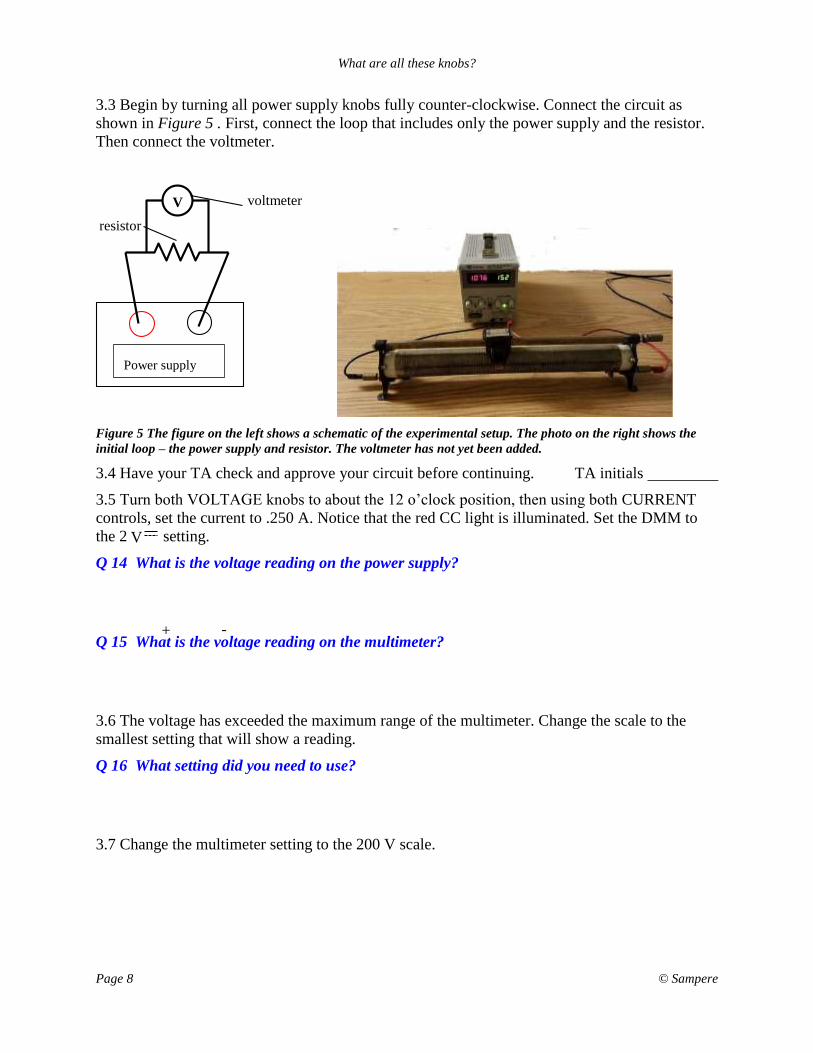
3.3 Begin by turning all power supply knobs fully counter-clockwise. Connect the circuit as
shown in Figure 5 . First, connect the loop that includes only the power supply and the resistor.
Then connect the voltmeter.
voltmeter V
resistor
Figure 5 The figure on the left shows a schematic of the experimental setup. The photo on the right shows the
initial loop – the power supply and resistor. The voltmeter has not yet been added.
3.4 Have your TA check and approve your circuit before continuing. TA initials
3.5 Turn both VOLTAGE knobs to about the 12 o’clock position, then using both CURRENT
controls, set the current to .250 A. Notice that the red CC light is illuminated. Set the DMM to
the 2 setting.
Q 14 What is the voltage reading on the power supply?
Q 15 What is the voltage reading on the multimeter?
3.6 The voltage has exceeded the maximum range of the multimeter. Change the scale to the
smallest setting that will show a reading.
Q 16 What setting did you need to use?
3.7 Change the multimeter setting to the 200 V scale.
Power supply
+ -
V

What are all these knobs?
Page 9 © Sampere
Q 17 What is the measured value now?
Q 18 Which setting should you use and why?
3.8 Change the DMM setting back to the 20V scale. Using the CURRENT controls, adjust the
current to read .500 and 1.00 amps while observing the voltage.
Q 19 Explain why changing the current knob affects the voltage reading?
3.9 Now increase the current to 1.500 A
Q 20 What happened when you attempted this? Did any lights change on the power supply? If
so, what changed?
3.10 Gradually, increase the VOLTAGE knobs to reach the desired current of 1.500 A.
Q 21 What are the voltage readings on the power supply and DMM now?
Q 22 What do you need to do to get a voltage reading on the DMM now?
4. Activity #4: Using an ammeter
4.1 Before dismantling your circuit, turn both CURRENT knobs fully CCW to make certain that
current will NOT flow. Then turn both VOLTAGE knobs fully CW. Gradually increase the
current to 0.150 A (150 mA). Leave the current knobs in this setting and adjust both voltage
knobs fully CCW to turn off the output of the power supply.
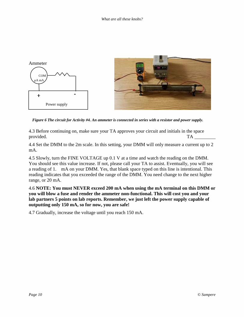
4.2 Wire the circuit as shown on the following page in Figure 6.
What are all these knobs?
Page 10 © Sampere
4.3 Before continuing on, make sure your TA approves your circuit and initials in the space
provided. TA
4.4 Set the DMM to the 2m scale. In this setting, your DMM will only measure a current up to 2
mA.
4.5 Slowly, turn the FINE VOLTAGE up 0.1 V at a time and watch the reading on the DMM.
You should see this value increase. If not, please call your TA to assist. Eventually, you will see
a reading of 1. mA on your DMM. Yes, that blank space typed on this line is intentional. This
reading indicates that you exceeded the range of the DMM. You need change to the next higher
range, or 20 mA.
4.6 NOTE: You must NEVER exceed 200 mA when using the mA terminal on this DMM or
you will blow a fuse and render the ammeter non-functional. This will cost you and your
lab partners 5 points on lab reports. Remember, we just left the power supply capable of
outputting only 150 mA, so for now, you are safe!
4.7 Gradually, increase the voltage until you reach 150 mA.
Power supply
Ammeter
Figure 6 The circuit for Activity #4. An ammeter is connected in series with a resistor and power supply.
µA mA
COM
What are all these knobs?
Page 11 © Sampere
Q 23 What is the voltage reading on the power supply when you reach 150 mA?
Q 24 What happens to the current reading if you try to further increase the VOLTAGE?
Q 25 What happens to the red CC and green CV lights as you adjust the voltage knob to go
below 150 mA and return to 150 mA?
Q 26 Does further increasing the voltage allow you to exceed 150 mA?
Q 27 An experiment requires that you not exceed a voltage of 6 V while being able to vary the
current and voltage. Explain how you would set up your power supply to ensure that you do
not blow up the circuit by exceeding 6 V.
Q 28 An experiment requires that you not exceed a current of 75 mA while being able to vary
the current and voltage. Explain how you would set up your power supply to ensure that you
do not blow up the circuit by exceeding 75 mA.

What are all these knobs?
Page 12 © Sampere
5. When you are finished ...
5.1 Make sure
5.1.1 All questions are answered and this report is turned in.
5.1.2 Your wires are all disconnected
5.1.3 The power supply is switched off and all controls are fully CCW.
5.1.4 Your DMM is switched off.