perma-cyl co 2000hp / 3000hp - chart industries
TRANSCRIPT

Part Number 20892356 Rev. A© 2016 Chart Inc.
Designed and Built by:
Chart Inc.1300 Airport Dr. Ball Ground, GA 30107 USA (800) 400-4683
Product ManualPerma-Cyl® CO2 MicroBulk Storage Systems
2000HP / 3000HP


iiiProduct Manual - Perma-Cyl® CO2 MicroBulk Storage Systems
ContentsRevision Log iv
Preface . . . . . . . . . . . . . . . . . . . . . . . . . . . . . . . . . . . . . . . . . . . . . . . . . . . . .1General 1Product Highlights 1Product Manual 1Terms 2Acronyms / Abbreviations 2
Safety . . . . . . . . . . . . . . . . . . . . . . . . . . . . . . . . . . . . . . . . . . . . . . . . . . . . .3General 3Safety Bulletin 3Oxygen Deficient Atmospheres 4Carbon Dioxide 4Personal Protective Equipment (PPE) 5
Introduction/Operation . . . . . . . . . . . . . . . . . . . . . . . . . . . . . . . . . . . . . . . . . . . .7General 7Initial Inspection 7Primary Plumbing Circuits 8
Fill 8Pressure Build 9Economizer 9Liquid Use 10Gas Use 10Safety Circuit 11Vent/Full Trycock 11Four-Way Valve 11Pressure Gauge 12Vacuum Evacuation Port 12
Purging and Fill Considerations 12Tank Purging Procedure 12Initial (Warm Tank) Filling Procedures 13
Installation . . . . . . . . . . . . . . . . . . . . . . . . . . . . . . . . . . . . . . . . . . . . . . . . . . 15Installation Common Codes and Standards 15Conducting a Site Evaluation 15Installation Tools and Supplies 15
Supplies 15Tools 15Additional Required Supplies 15
Indoor Installations 16Internally Sited / Filled Indoors / Pipe Out Safeties 16Wall Box 16
Installation of Hoses and Lines 17General 17Line Connection to Fill Box Panel 17Bolting to Floor 18
Outdoor Installations 19Externally Sited / Gas Use Indoors 19Outdoor Installation Schematic 19
Troubleshooting . . . . . . . . . . . . . . . . . . . . . . . . . . . . . . . . . . . . . . . . . . . . . . . 21
Specifications . . . . . . . . . . . . . . . . . . . . . . . . . . . . . . . . . . . . . . . . . . . . . . . . 25

iv Table of Contents Product Manual - Perma-Cyl® CO2 MicroBulk Storage Systems
Revision LogRevision Level Date Description
A 08/04/2016 Original
Illustrations & Parts Listing . . . . . . . . . . . . . . . . . . . . . . . . . . . . . . . . . . . . . . . . 272000/3000 HP CO2 Parts Listing 272000/3000 HP CO2 Top View 282000/3000 HP CO2 Front View 292000/3000 HP CO2 Detail Views 29
1Product Manual - Perma-Cyl® CO2 MicroBulk Storage Systems
GeneralThe Perma-Cyl 2000 and 3000 HP CO2 MicroBulk Storage Systems are specifically designed for CO2 service One notable performance improvement is the fast fill feature - at least three times the fill rate over our standard Perma-Cyl Series from a typical beverage delivery truck. The upsizing and redesign of the top fill eductor circuit reduces the overall fill time, and also reduces the amount of vent gas during delivery for a more efficient fill. Other new design features include larger internal pressure builder and vaporizer coils, allowing for faster pressure recovery and increased gas flow rates. Dedicated pressure builder and economizer regulators also contribute to this improved performance.
The Perma-Cyl CO2 tank comes with many of the standard features found on the Perma-Cyl Series for easy installation and fast start up. The Perma-Cyl Series is well known for holding its liquefied gas contents for long periods of time without venting, thus limiting product loss during periods of little or no gas use
Product HighlightsThe better alternative to full-for-empty cylinders• Replaces HP cylinders
• Extended hold time over liquid cylinders
• Easy low-cost installation - indoors or outdoors (local codes permitting)
• Safety devices pipe-away required for indoor installation
Fast, efficient fills• Efficient fill circuit reduces fill times and vent losses
• Fill rates up to 170 lbs/min*
High-performance vaporizer• Up to 500 scfh at 300 psig**
• Available in 125 psig and 300 psig operating pressures
• Dedicated Pressure Builder (1/2”) and economizer regulators
Cyl-Tel® Liquid Level Gauge• Digital and accurate
• Built-in user selectable scales
• Telemetry ready
Ergonomic instruments and controls• Located at user height
• Isolation valves for regulators and level gauge
Long life, low maintenance• Stainless steel bottle and welded piping
• Heavy-duty galvanized pallet base
*Pressure transfer performance from 33% full at 125 psig to 90% full in 12 minutes with delivery vessel at 295 psig starting pressure without Perma-Cyl storage tank venting
**Based on twelve hours per day of continuous duty at 68°F and 50% RH ambient conditions with internal vaporizer.
Product ManualThis manual contains information regarding the safe operation and maintenance of a Perma-Cyl CO2 MicroBulk Storage System It should be thoroughly read and understood by anyone that operates the equipment.
The schematics, piping illustrations, and parts list show a reference number for each component used on the tank. The reference numbers may refer to the same functional component between the various models. The reference numbers will be used throughout this manual to draw specific attention to a component while describing its function, operation, or repair.
The safety requirements for operating the tank and handling or transporting extremely cold liquid products are shown in the Safety section Use this safety section as a “Safety Checklist” each time the equipment is being used.
The Introduction section discusses the general features of the tank and the theory of operation.
In the Installation section there are illustrations for how to uncrate and install the tank
The remaining sections describe the specific tank models covered by this manual. They contain warranty information, troubleshooting help, technical specifications/illustrations, and parts lists. They should be reviewed first and referred to as the rest of the manual is read
Preface

2 Preface Product Manual - Perma-Cyl® CO2 MicroBulk Storage Systems
TermsThroughout this manual safety precautions will be designated as follows:
Warning! Description of a condition that can result in personal injury or death.
Caution! Description of a condition that can result in equipment or component damage.
Note: A statement that contains information that is important enough to emphasize or repeat.
Acronyms / AbbreviationsThe following acronyms / abbreviations are used throughout this manual:
ASME American Society of Mechanical Engineers
BARG Pressure Gauge (Metric)
CGA Compressed Gas Association
CO2 Carbon Dioxide
DP Differential Pressure
FPT Female Pipe Thread
ID Inner Diameter
Kg Kilogram
MAWP Maximum Allowable Working Pressure
Nm3 Normal Cubic Meters
NER Normal Evaporation Rate
NFPA National Fire Protection Association
NPT National Pipe Tapered Thread
PB Pressure Builder
PN Part Number
PPE Personal Protective Equipment
PSI Pounds per Square Inch
PSIG Pounds per Square Inch (Gauge)
SCFH Standard Cubic Feet/Hour
UFC Uniform Fire Code

3Product Manual - Perma-Cyl® CO2 MicroBulk Storage Systems
GeneralWhile Chart equipment is designed and built to the most rigid standards, no piece of mechanical equipment can ever be made 100% foolproof. Strict compliance with proper safety and handling practices are necessary when using a cryogenic manifold device or other compressed gas equipment. We recommend that all of our customers re-emphasize safety and safe handling practices to all their employees and customers. While every possible safety feature has been designed into the Perma-Cyl® MicroBulk Storage System and safe operations are anticipated, it is essential that the customer carefully read and fully understand all Warning and Caution notes listed below.
Warning! The Perma-Cyl tank, with its stainless steel support system is designed, manufactured, and tested to function normally for many years of service. It is never safe to drop a liquid cylinder or let it fall over in cryogenic service. In the event a liquid cylinder is inadvertently dropped, tipped over, or abused, slowly raise it to its normal vertical position and immediately open the vent valve to release any excess pressure in a safe manner. As soon as possible, remove the liquid product from the vessel in a safe manner. If damage is evident or suspected, return the unit to Chart prominently marked “LIQUID CYLINDER DROPPED, INSPECT FOR DAMAGE”.
Warning! Any welding that is done on the outside of the Perma-Cyl System can cause loss of vacuum and will VOID any warranty on the unit.
Warning! Before removing cylinder parts or loosening fittings, completely empty the liquid cylinder of liquid and release the entire vapor pressure in a safe manner. External valves and fittings can become extremely cold and may cause painful burns to personnel unless properly protected. Personnel must wear protective gloves and eye protection whenever removing parts or loosening fittings. Failure to do so may result in personal injury because of extreme cold and pressure in the cylinder.
Caution! Only use replacement equipment which is compatible with liquid oxygen and has been cleaned for oxygen use. Do not use regulators, fittings, hoses, etc., which have been previously used in compressed air service. Failure to comply with these instructions may result in serious damage to the liquid cylinder and personal injury.
Caution! All valves on an empty Perma-Cyl system should always be kept closed to protect the inner vessel and plumbing from being contaminated.
Safety BulletinPortions of the following information are extracted from Safety Bulletin SB-2 from the Compressed Gas Association, Inc
Cryogenic containers, stationary or portable, are from time to time subjected to assorted environmental conditions of an unforeseen nature This safety bulletin is intended to call attention to the fact that whenever a cryogenic container is involved in any incident whereby the container or its safety devices are damaged, good safety practices must be followed. The same holds true whenever the integrity or function of a container is suspected of abnormal operation.
Incidents which require that such practices be followed include: highway accidents, immersion of a container in water, exposure to extreme heat or fire, and exposure to most
Safety

4 Safety Product Manual - Perma-Cyl® CO2 MicroBulk Storage Systems
adverse weather conditions (earthquake, tornadoes, etc.). Under no circumstances should a damaged container be left with product in it for an extended period of time.
Prior to reusing a damaged container, the unit must be tested, evaluated, and repaired as necessary. It is highly recommended that any damaged container be returned to Chart for repair and re-certification.
In the event of known or suspected container vacuum problems (even if an extraordinary circumstances such as those noted above has not occurred), do not continue to use the unit Continued use of a cryogenic container that has a vacuum problem can lead to embrittlement and cracking.
The remainder of this safety bulletin addresses those adverse environments that may be encountered when a cryogenic container has been severely damaged These are oxygen deficient atmospheres, oxygen enriched atmospheres, and exposure to inert gases.
Caution! Before locating oxygen equipment, become familiar with the NFPA standard No. 55 “Compressed Gases and Cryogenic Fluids Code” (www.nfpa.org) and with all local safety codes.
Oxygen Deficient AtmospheresThe normal oxygen content of air is approximately 21%. Depletion of oxygen content in air, either by combustion or by displacement with inert gas, is a potential hazard and users should exercise suitable precautions.
One aspect of this possible hazard is the response of humans when exposed to an atmosphere containing only 8 to 12% oxygen. In this environment, unconsciousness can be immediate with virtually no warning.
When the oxygen content of air is reduced to about 15 to 16%, the flame of ordinary combustible materials, including those commonly used as fuel for heat or light, may be extinguished. Somewhat below this concentration, an individual breathing the air is mentally incapable of diagnosing the situation because the onset of symptoms such as sleepiness, fatigue, lassitude, loss of coordination, errors in judgment and confusion can be masked by a state of “euphoria,” leaving the victim with a false sense of security and well being.
Human exposure to atmosphere containing 12% or less oxygen leads to rapid unconsciousness. Unconsciousness can occur so rapidly that the user is rendered essentially helpless.
This can occur if the condition is reached by an immediate change of environment, or through the gradual depletion of oxygen
Most individuals working in or around oxygen deficient atmospheres rely on the “buddy system” for protection - obviously the “buddy” is equally susceptible to asphyxiation if he or she enters the area to assist the unconscious partner unless equipped with a portable air supply. Best protection is obtainable by equipping all individuals with a portable supply of respirable air. Life lines are acceptable only if the area is essentially free of obstructions and individuals can assist one another without constraint.
If an oxygen deficient atmosphere is suspected or known to exist:
1 Use the “buddy system.” Use more than one “buddy” if necessary to move a fellow worker in an emergency.
2 Both the worker and “buddy” should be equipped with self-contained or airline breathing equipment.
Carbon DioxideThe system described in this manual has the ability to hold and dispense carbon dioxide (CO2) gas under pressure.
Warning! Asphyxiation hazard. Carbon dioxide gas can cause serious injury or death. Do not breathe CO2 gas. Avoid entering tank area if a leak is suspected and thoroughly ventilate area.
CO2 gas is a colorless, odorless, tasteless gas that displaces oxygen and in certain percentages does not support life. The gas is difficult to detect without the assistance of special equipment. Avoid breathing or contacting CO2 in gas, liquid or solid form
Exposure to concentrations of less than 5% for less than 15 minutes can cause physical symptoms including unconsciousness, injuries or death. Even low concentrations of CO2 can cause:
• Dizziness, headaches, nausea or disorientation
• Increased respiration or heart rate
• Shortness of breath or rapid suffocation
It is important to note that unlike nitrogen and argon, exposure to high concentrations of CO2 can be deadly even when normal percentages of oxygen are present in the surrounding atmosphere.

5SafetyProduct Manual - Perma-Cyl® CO2 MicroBulk Storage Systems
CO2 is heavier than air and can collect in low areas such as basements, stairwells, and confined spaces. Avoid entry into areas where CO2 leaks or high concentrations of CO2 are suspected. Enter those areas with caution only after they have been thoroughly ventilated
Whenever the vessel is inside a building it’s safety relief circuit must be connected to an outdoor vent typically in the fill box. The fill box and/or vent must never be located in or above any below-ground spaces or stairwells. The vessel must not block emergency exits, aisles, fire suppression equipment or utility boxes or accesses. CO2 lines or hoses must be located away from traffic areas and heat sources and must be protected from potential causes or damage. All connections, lines, and components must be leak-free.
This equipment should be installed and serviced only by professional agents who are qualified to work with CO2 and the mini-bulk liquid CO2 storage vessels They should be familiar with all pertinent safety procedures.
Personal Protective Equipment (PPE)The following personal protective equipment is recommended when working around cryogenic liquid:
• Safety glasses with side shields to prevent cryogenic liquid from splashing into the eyes
• Chemical / Liquid resistant gloves to prevent cryogenic burns on exposed hands
• Long sleeve shirts to protect the arms
• Cuffless trousers worn over closed shoes


7Product Manual - Perma-Cyl® CO2 MicroBulk Storage Systems
GeneralThe Perma-Cyl CO2 MicroBulk Storage System is designed to store and deliver carbon dioxide as a cryogenic liquid The Perma-Cyl tank can build and maintain pressure from the automatically regulated pressure building circuit. A continuous liquid or gas flow can be provided from these cylinders. Regardless of size, all Perma-Cyl tank models operate on much the same principals of operation.
Initial InspectionUpon receipt of a Perma-Cyl tank, remove the protective wrapping and inspect for the following:
• Check the outer shell of the tank There should be no visible signs of damage such as dents or deep scratches.
• Check the piping on the tank, there should be no visible signs of damage
• Check that the tank has pressure, normally about 20 psi.
• If the tank passes all the above criteria, it is ready to install and fill. Follow the installation and fill procedures outlined in the Installation and Filling section of this manual
Introduction/Operation
Figure 1 - Schematic for 2000HP and 3000HP models

8 Introduction/Operation Product Manual - Perma-Cyl® CO2 MicroBulk Storage Systems
Primary Plumbing Circuits(see Figure 1)
Fill
The liquid fill circuit is used to top fill the Perma-Cyl tank using the Chart designed eductor tube (see Figure 2A) on the inside to assist in controlling the tank pressure during the fill. The fill line has a check valve (CV-4) and service fitting that provide the sole pressure connection for the delivery vehicle (see Figure 2). Several examples of common CO2 service fittings are shown in Figure 1 (a, b, c, & d).
During a first fill, only fill the vessel to 75% full to allow liquid expansion experienced with a new "hot" tank. Each fill thereafter can be filled to 100% full. Please refer to the Installation section of this manual for detailed filling procedures.
Fill isolation valves can be ordered as an option kit in addition to the standard check valve (see Figure 3).
Caution! If liquid can be trapped in the transfer system, a suitable relief valve must be installed to prevent over pressurization.
Figure 1A - 5/8" flare fitting shipped on Beverage Tanks
Figure 1B - Snap-Tite Fitting shipped separately on standard and CO2 Perma-Cyl tanks
Figure 1C - CGA 622 Fitting shipped on standard Perma-Cyl tanks
Figure 1D - 1" CGA Fitting shipped on Perma-Cyl CO2 2000/3000 HP tanks
Figure 2 - Fill Line

9Introduction/OperationProduct Manual - Perma-Cyl® CO2 MicroBulk Storage Systems
Figure 2A - Eductor Tube
Figure 3 - Fill Isolation Valve
Pressure Build
The pressure build circuit is used to build pressure back in the vessel after a delivery or to maintain pressure as liquid is withdrawn from the vessel. The vessel pressure is set by adjusting the PB regulator (R2). Standard PB set points are:
MP - 125 psig
HP - 300 psig
As the tank pressure drops below the PB set point, the regulator opens and allows liquid to flow off the bottom of the tank, through the internal PB vaporization coils, through the R-2 and back into the gas phase of the tank as depicted in Figure 1. The pressure build regulator can be isolated by closing valves V-8 and V-9 The PB regulator and isolation valves are shown in Figure 4.
The CO2 Perma-Cyl tanks can be equipped with external pressure build vaporizers which allow for much quicker recoveries after the tank has been blown down to fill it or for high flow applications (see Figure 5).
Figure 4 - PB Regulator with Isolation Valves
Figure 5 - External PB Vaporizer
Economizer
The economizer circuit (see Figure 6) allows for the customer to utilize the natural heat leak that occurs in every cryogenic storage vessel. When the pressure is above the set point of the economizer regulator (R-1), the regulator opens. This allows gas to be withdrawn directly off the headspace of the tank and travel through the internal vaporization coils, in order to warm the cold gas, and out the gas use valve as depicted in Figure 1. This will result in lowering the pressure of the tank
Note: The economizer circuit will only work if the customer is using product out of the vessel.

10 Introduction/Operation Product Manual - Perma-Cyl® CO2 MicroBulk Storage Systems
The economizer regulator can be isolated by closing valves V-6 and V-2
Figure 6 - Economizer Regulator with Isolation Valves
Liquid Use
The liquid use circuit can be used for both a liquid application or a high flow gas use application. This circuit draws liquid directly up the dip tube as depicted in Figure 1, and out through the liquid use valve (V-3). The liquid use valve is a blue handled ball valve (see Figure 7). For high flow gas use applications, the liquid can be piped through a stand alone external process vaporizer. This can more than double the standard flow rates that can be achieved through the internal vaporization coils.
Figure 7 - Liquid Use ball valve
Gas Use
The gas use valve (V-1) leverages the internal vaporization coils contained within the outer shell of the Perma-Cyl tank. The internal vaporization coils can support specific flow rates as outlined in the Specification section on page 25. The gas use valve is pictured in Figure 8. The gas use line running into the customer's facility should be sized properly for anticipated pressure and flowrates to include room for future growth. In the event that the internal vaporization coils are not able to handle the flowrates and exit temperatures become a problem, an external vaporizer can be added to further warm the gas (see Figure 5). Attach this vaporizer directly in series with the gas use connection and place the line regulator at the exit of the vaporizer. The liquid use valve as outlined in the "Liquid Use" paragraph can also be used for high flow applications that exceed the rating of the vaporization coils.
The Perma-Cyl tank will deliver gas at various flow rates and temperatures for different applications. The equipment that is being supplied gas from the Perma-Cyl tank controls the flow rate. Higher flow rates may provide very cold gas that could damage the equipment to which they are attached. To supply gaseous product, follow this step by step procedure.
1 Connect the proper regulator/regulating manifold to the liquid cylinder's gas use outlet Regulating manifolds can also be ordered as an option which are included on the tank
2 Connect the proper piping between the final line regulator and the receiving equipment.
3 Open the pressure building valve.
4 Allow pressure to build to the operating pressure (refer to gauge).
5 Open the gas use valve.
6 Adjust the gas use regulator for the proper delivery pressure.
Caution! All valves on an empty Perma-Cyl tank should always be kept closed to protect the inner vessel and plumbing from being contaminated.
The operator should review the safety precautions found in the Safety section before conducting a gas or liquid withdrawal operation. Protective eyeglasses and gloves should always be worn.

11Introduction/OperationProduct Manual - Perma-Cyl® CO2 MicroBulk Storage Systems
Figure 8 - Gas Use ball valve
Safety Circuit(see Figure 9)
Most Perma-Cyl tanks are equipped with both a primary spring operated relief valve and a secondary spring operated relief valve These devices are used to automatically relieve excess pressure in the vessel and cannot be isolated by the use of a valve. Replacement of these relief devices should only be on a "like for like" basis. Substitutes should be avoided unless approved by the manufacturer. The diverter valve allows for changing out safety relief devices without the need to empty the tank.
Figure 9 - Safety Relief Valves with Diverter Valve
Vent/Full Trycock(see Figure 10)
The vent valve is used to relieve excess pressure in the cylinder On CO2 Perma-Cyl systems the vent valve is a blue handled ball valve (V-5). When installed indoors, the vent line should be piped outdoors using the appropriately sized copper or stainless steel tubing. The vent valve also serves as the full trycock during filling operations. When the Perma-Cyl tank is filled by pumping or pressure transfer, the full trycock must be used to fill the vessel. When liquid starts to spit out of this valve while being filled, the filling process should be terminated
Figure 10 - Vent/Full Trycock
Four-Way Valve
The four-way valve (V-7) is used as the primary isolation valve between the DP gauge and the phase lines from the tank. This four-way valve also provides an easy method to check the zero on the DP gauge By turning the valve into the equalization position, the DP gauge can be zeroed and isolated from the tank pressure for removal or replacement.
Figure 11 - Four-Way Valve
Four-Way Valve
Pressure Gauge
Cyl-Tel® Liquid Level
Gauge

12 Introduction/Operation Product Manual - Perma-Cyl® CO2 MicroBulk Storage Systems
Pressure Gauge
A single pressure gauge (P-1) on the Perma-Cyl tank is also tied into the low phase line and gives the operator a pressure reading in the gas phase of the vessel. This pressure gauge can also be isolated with the four-way valve.
Figure 12 - Pressure gauge
Vacuum Evacuation Port
Unlike bulk tanks, Perma Cyl storage vessels are normally not provided with an on-board method of taking a vacuum reading. The vacuum evacuation port is sealed using a stainless steel disk with O-rings and a protective cover is placed over it. (see Figure 13). Due to the relatively small volume of the annular vacuum space, taking vacuum readings is normally not recommended due to the fact that the vacuum level is slightly reduced when taking this reading. The troubleshooting portion of this manual gives steps on how to determine if the vacuum might be weak. In the event that the vacuum does need to be checked, a trained vacuum technician would have to bring the appropriate equipment to get this done. In most cases where a vacuum has been compromised, it is often more economical to swap out the tank
Figure 13 - Vacuum Evacuation Port with Cover
Purging and Fill ConsiderationsThe initial fill is usually performed on a warm tank - one that has not been in use for an extended period of time prior to filling. The warm container must be purged to ensure product purity.
When preparing the tank for filling, or when changing service, the following items should be considered:
1 The vessel should be inspected for possible damage or unsuitability for the intended use If damage is detected (i.e. serious dents, loose fittings, etc.), remove the unit from service and perform repairs as soon as possible.
2 The vessel should be kept at normal operating pressures above 100 psig to prevent the liquid CO2 temperature from dropping below the triple point pressure and forming dry ice
Caution! Liquid CO2 should never be stored at pressures below 60.5 psig (4.3 kg/cm2) as this will result in the formation of solid CO2 which can be very difficult to remove from the tank.
3 To remove moisture or foreign matter from the tank or tank lines, the vessel must be purged. Use a small amount of the new product for purging when changing service and a small amount of the same product if the purge is to ensure purity or remove contaminants.
Tank Purging ProcedureCaution! The maximum purge pressure
should be equal to 50% of the maximum operating pressure of the tank. The maximum purge pressure must be determined before starting the purge operation to prevent drawing atmospheric contaminants back into the tank. A positive pressure of at least 5 psig must always be maintained in the tank.
1 Attach the source of gas purge product to the fill line (FC-1).
Note: Chart CO2 storage tanks ship with brass plugs in the following valves: auxiliary liquid valve (V-3), vent valve (V-5) and gas use valve (V-1). These plugs are to be removed at time of installation.
Four-Way Valve
Pressure Gauge
WIKA Analog DP
Gauge
Evacuation Port

13Introduction/OperationProduct Manual - Perma-Cyl® CO2 MicroBulk Storage Systems
2 If the fill hose has not been kept under pressure since the last delivery, it will need to be purged. Purge the fill hose through the tank or hose purge valve if so equipped, or by loosening the fill connection until vapor flows from the connection and then retighten.
3 Close all valves except the pressure building inlet and outlet valves (V-8 and V-9), four-way valve (V-7) should be in the 'normal operation" position.
Note: When a solenoid valve is used to control the pressure building circuit, it must be energized.
4 Open the vapor valve on the delivery truck to allow gas to flow into the tank.
Caution! To prevent snow blocking the plumbing lines, do not introduce liquid CO2 into the vessel or plumbing until the tank is pressurized to at least 100 psig with vapor.
5 Shut off the gas supply source on the delivery vehicle when pressure in the tank reaches the maximum purge pressure as indicated on tank pressure gauge (PI-1).
6 Place the four-way valve (V-7) in the equalization position to prevent damage to the gauge.
7 Loosen the fittings on either side of the liquid level gauge (Ll-1). Move the four-way valve to the normal operation position and purge through the loose fittings. Visually check the gas stream for signs of moisture Provided no moisture is observed after blowing the lines for approximately two minutes, retighten the fittings on either side of the liquid level gauge If moisture is observed in the gas stream, the gas should be discharged until it is clear of all moisture
Note: A careful check for moisture in the phase lines will ensure trouble-free operation of the liquid level gauge. Due to their small diameter, gauge lines are easily plugged by ice.
8 Open the purge valves on the safety relief tree (PCV-3A/B) toggle the safety diverter valve (V-4) to both sides to purge entire circuit. Close purge valves after purging.
9 Ensure the pressure build regulator is open and purge gas is circulating through this circuit
10 Close the economizer isolation valves (V-2 & V-6). Remove safety relief valve (RV-3). Open economizer isolation valves and purge economizer circuit for several minutes. Replace RV-3 and open V-2 and V-6.
11 Open the liquid use, gas use, and vent valves and purge tank to reduce the pressure to 5 psig.
Warning! Hearing protection must be worn while tank is venting.
12 Repeat purge procedures steps 3, 4, 5 and 11 at least five times until product purity has been obtained.
13 Ensure four-way valve is in the "normal operation" position.
14 Pressure check all valves and fittings while tank is under pressure during purge procedure.
15 After purging the tank, but before filling, verify that the following valves are open or closed as indicated in the table
Valve PositionVent/Full Trycock Valve (V-5) ClosedLiquid Withdrawal Valve (V-3) ClosedGas Use Valve (V-1) ClosedPressure Building Inlet Valve (V-9) ClosedPressure Building Outlet Valve (V-8) ClosedEconomizer Inlet Isolation Valve (V-2) ClosedEconomizer Outlet Isolation Valve (V-6) Closed
Initial (Warm Tank) Filling Procedures1 Purge tank to assure product purity (see tank purging
procedure).
2 Verify that the supply unit contains the proper product to be transferred and that the supply unit and tank fill fitting are for CO2 service
3 Verify that all valves are closed and the four-way valve is in the "normal operation" position.
4 Connect the supply unit liquid transfer hose to the tank fill connection (FC-1) and ensure that it is properly purged.
5 Connect the vapor recovery transfer hose to the tank vent/full trycock connection (V-5)(for two-hose fill operation only).

14 Introduction/Operation Product Manual - Perma-Cyl® CO2 MicroBulk Storage Systems
6 Open vent valve (V-5) slowly and allow the tank and delivery unit to equalize in pressure (for two-hose fill operation only).
7 If two-hose fill is not being used, ensure that the tank is pressurized to at least 100 psig with vapor off of the delivery unit before introducing liquid into the tank
8 Once tank is at the proper pressure (for single hose fill), open the liquid discharge valve on the delivery unit and start the transfer pump (if equipped). If using pressure transfer, liquid will being to flow into the Perma-Cyl through the fill connection.
9 Monitor the tank pressure during the fill and ensure that at least a 50 psig differential is maintained between the tank and delivery unit if using a pump or utilizing pressure transfer. For pressure transfer, the higher the differential, the faster the tank will fill. Maintain differential by opening the vent/full trycock valve during the fill (if using a single hose fill).
10 During the first fill of a warm tank, pressure may spike very quickly once liquid starts flowing into the tank. Open the vent/full trycock to keep pressure down until tank stabilizes. If pressure raises too quickly, it may be necessary to temporarily stop the filling operation and blow the tank down before starting to fill again.
11 Monitor liquid level contents gauge (Ll-1) during filling.
12 If using a two-hose fill procedure, when the tank nears full, open the vent/full trycock line drain valve on the delivery vessel. Stop the filling operation when liquid begins to discharge from the drain valve
13 If using a single-hose fill procedure, when the tank nears full, open the vent/full trycock valve and let it blow to atmosphere. Stop the filling operation when the liquid begins to discharge from the vent valve (V-5).
Note: Ontheveryfirstfill,itisnormallygoodpractice to leave the tank at a liquid level of about 75% since the tank will continue tocooldownforthefirstfewdaysafterfilling.
14 Once liquid is discharging out of the vent/full trycock valve, close the valve.
15 Stop the pump on the delivery unit (if equipped) and close the liquid discharge valve. Drain all the pressure off of the delivery hoses and disconnect from the tank Store the hose(s) in the cabinet of the delivery vehicle.
16 Unit is now ready to place into service. Ensure that PB isolation valves (V-8 & V-9), economizer isolation valves (V-2 & V-6), and gas use valves are open after first fill is completed.
15Product Manual - Perma-Cyl® CO2 MicroBulk Storage Systems
Installation Common Codes and StandardsThe installer will need to find out what local city ordinances and which rules they are mandated to follow. One of the following standards may apply; Uniform Fire Code (UFC), Compressed Gas Association (CGA), and the National Fire Protection Association (NFPA).
Note: Regulations vary in every part of the country. Always consult local codes!
Conducting a Site EvaluationBefore a Perma-Cyl System is installed a site evaluation should be conducted. This trip to the customer’s site will help identify any special needs that each site invariably has. While on site, note what application the Perma-Cyl System will be used for. Decide whether the installation will be inside or outside Proximity to the CO2 Delivery System fill point and the user’s equipment should be taken into account in making this decision. When the placement has been set, take measurements of how much and where the piping will be run
Installation Tools and SuppliesInstallation of the Perma-Cyl System requires that certain tools and supplies are available. For simple and economical installations, the following supplies and tools should be maintained, however, not all installations will require them.
Supplies• Silicone Sealant (clear and white)
• PVC Cement
• 1/4” Plastic Screw Anchors
• Self-tapping Screws
• 9” Cable Ties
• Duct Tape
• Teflon Tape
• Chalk or Marker
• Leak Check Solution
Tools
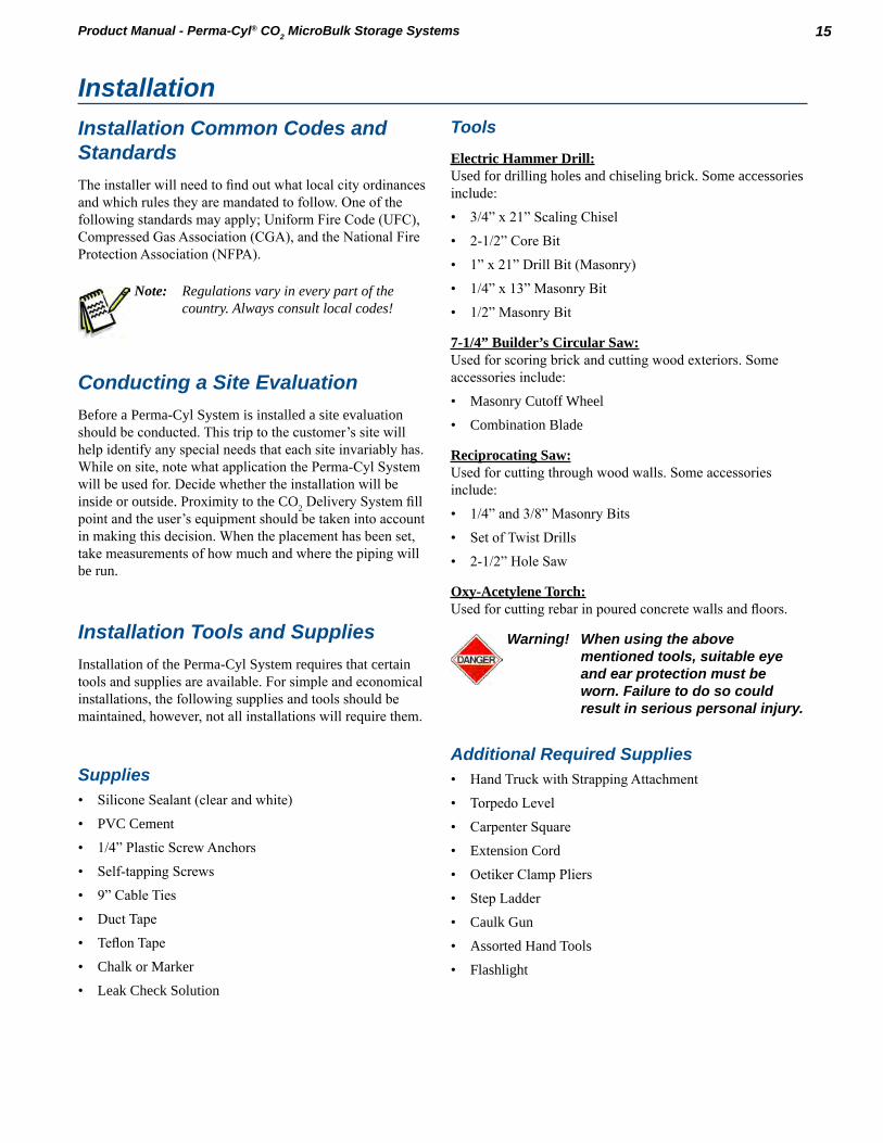
Electric Hammer Drill:Used for drilling holes and chiseling brick Some accessories include:
• 3/4” x 21” Scaling Chisel
• 2-1/2” Core Bit
• 1” x 21” Drill Bit (Masonry)
• 1/4” x 13” Masonry Bit
• 1/2” Masonry Bit
7-1/4” Builder’s Circular Saw:Used for scoring brick and cutting wood exteriors. Some accessories include:
• Masonry Cutoff Wheel
• Combination Blade
Reciprocating Saw:Used for cutting through wood walls. Some accessories include:
• 1/4” and 3/8” Masonry Bits
• Set of Twist Drills
• 2-1/2” Hole Saw
Oxy-Acetylene Torch:Used for cutting rebar in poured concrete walls and floors.
Warning! When using the above mentioned tools, suitable eye and ear protection must be worn. Failure to do so could result in serious personal injury.
Additional Required Supplies• Hand Truck with Strapping Attachment
• Torpedo Level
• Carpenter Square
• Extension Cord
• Oetiker Clamp Pliers
• Step Ladder
• Caulk Gun
• Assorted Hand Tools
• Flashlight
Installation
16 Installation Product Manual - Perma-Cyl® CO2 MicroBulk Storage Systems
Indoor InstallationsRequired:
• Room size - Air volume must allow oxygen level to stay between 18% to 25%
• Increased ventilation
• Valves vented outside (including mobile tanks)
• CO2 monitors required for all CO2 installations
Preferred:
• Sealed off away from other work areas
• Ground level next to outside wall
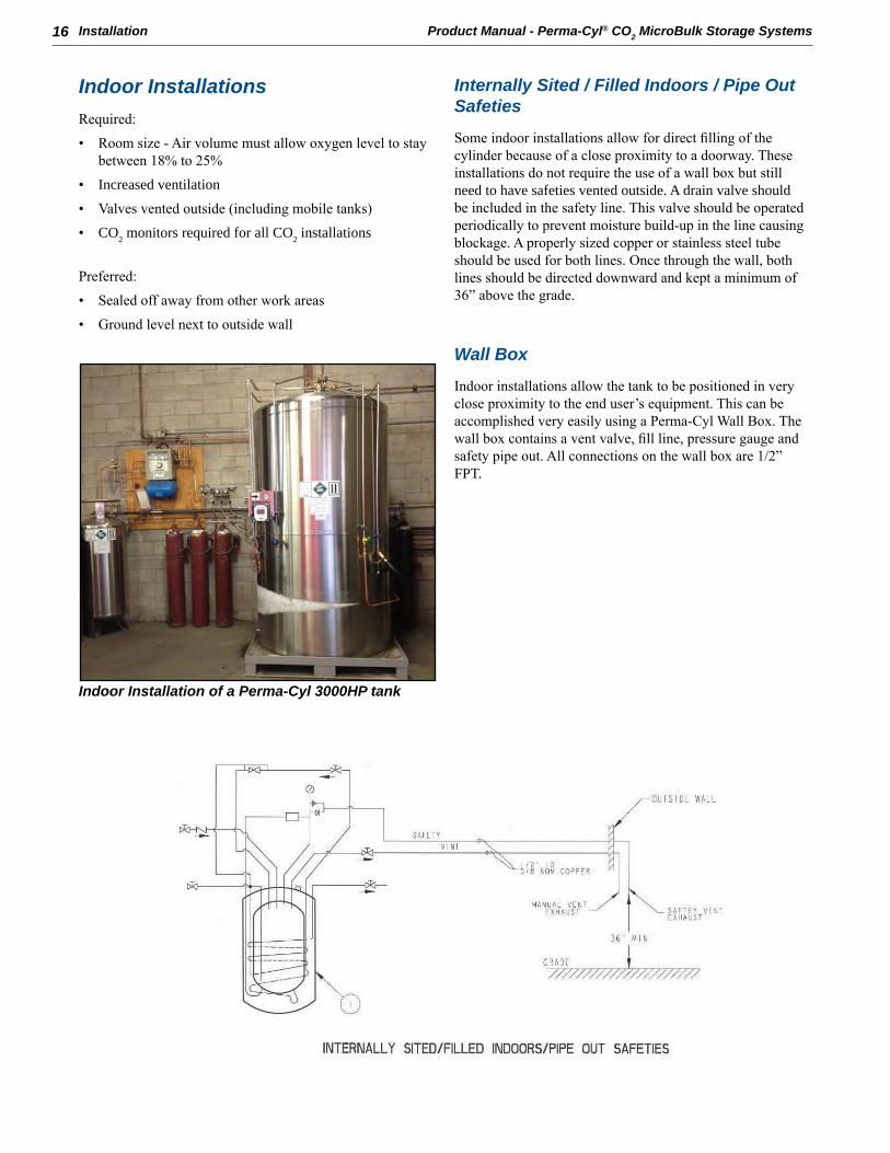
Indoor Installation of a Perma-Cyl 3000HP tank
Internally Sited / Filled Indoors / Pipe Out Safeties
Some indoor installations allow for direct filling of the cylinder because of a close proximity to a doorway. These installations do not require the use of a wall box but still need to have safeties vented outside A drain valve should be included in the safety line. This valve should be operated periodically to prevent moisture build-up in the line causing blockage. A properly sized copper or stainless steel tube should be used for both lines. Once through the wall, both lines should be directed downward and kept a minimum of 36” above the grade.
Wall Box
Indoor installations allow the tank to be positioned in very close proximity to the end user’s equipment. This can be accomplished very easily using a Perma-Cyl Wall Box. The wall box contains a vent valve, fill line, pressure gauge and safety pipe out. All connections on the wall box are 1/2” FPT

17InstallationProduct Manual - Perma-Cyl® CO2 MicroBulk Storage Systems
Installation of Hoses and Lines
General
Running the liquid fill hose and vent hoses from the fill box to the tank, will most likely be done differently at each location. By following the basic rules and guidelines listed below, the lines can be run easily and as simply as possible. A typical wall box installation is diagrammed below. Note the guidelines for piping to be used.
1/2” Connections on back of wall box
Line Connection to Fill Box Panel
1 Fasten NPT connection on vent hose to the NPT fitting on the back of the control panel.
2 Fasten NPT connection on fill hose to the NPT fitting on the back of the control panel.
3 Fasten NPT connection on safety vent to the NPT connection on the back of the wall box.
4 Feed all lines back into building while pushing panel back into the fill box.
5 Loosely fasten panel into box (it will be removed for pressure checking later).
Connections on the wall box are provided for the vent line, liquid fill and relief line.
• Liquid Fill Line - The liquid fill should be piped using a minimum diameter of 3/4” nominal copper or stainless steel pipe or tube. The line should be connected from the fill connection in the wall box to the liquid fill check valve on the Perma-Cyl System. When piping this line there are a few guidelines that should be followed.

18 Installation Product Manual - Perma-Cyl® CO2 MicroBulk Storage Systems
– Bends and elbows should be kept at a minimum. When needed they should be made with a wide bend radius. A minimum bend radius of 6” should be observed
– The length of the line from the tank to the box should be kept to a minimum. Bare copper line can be used for lines. If bare copper is used, it should be insulated using air conditioning foam to keep condensation from dripping off the piping.
– Line size should be a minimum 5/8” ID.
• Vent Line - The vent line should be run using a minimum of 1/2” nominal copper or the stainless steel pipe or tubing This vent line should connect the vent valve in the wall box to the vent valve on the Perma-Cyl System.
• Relief Line - The relief line should be run using copper or stainless steel pipe or tubing. Sizing is depended on the length of the line and number of bends/restrictions
Caution! Improperly sized relief discharge piping can put high back pressures against the primary and secondary relief valve, thus reducing their capacity potentially creating an unsafe condition.
Bolting to Floor
The Perma-Cyl tank is equipped with a flange on the bottom that has four holes for attachment To ensure a safe environment, the tank should be bolted to the floor.
1 Place tank in position with gauges facing forward.
2 Mark holes on floor, move tank.
3 Drill holes using the appropriate size masonry bit.
4 Blow out dust and insert masonry anchors.
5 Move tank back into position over holes and install lag bolts
6 Tighten bolts

19InstallationProduct Manual - Perma-Cyl® CO2 MicroBulk Storage Systems
Outdoor InstallationsRequired:
• Open
• Well ventilated
• At or above ground level
Perma-Cyl 2000HP with external pressure build vaporizer
Figure 6Externally Sited/Gas Use Installation
Externally Sited / Gas Use Indoors
Outdoor installations can offer better accessibility for the CO2 Delivery System for filling purposes. Also, lines do not need to be run except from the tank to the user’s equipment. Outdoor installations should be made on a concrete pad. Local soil conditions and seismic codes will affect the thickness and reinforcement required for the concrete pad. The Perma-Cyl tank should be bolted to the concrete pad using appropriate sized anchor bolts. Also in outdoor installations, a fence can provide added protection for the Perma-Cyl system and work to eliminate tampering with any plumbing component.
Outdoor Installation Schematic
At a minimum, installation should include a final line regulator and a check valve. A typical piping schematic is depicted in Figure 6.
Item # Description1 Perma-Cyl Storage Tank2 Final Line Regulator3 Final Line Safety Relief4 Final Line Check Valve5 Back-up Supply Isolation Valve


21Product Manual - Perma-Cyl® CO2 MicroBulk Storage Systems
Trouble Probable Cause RemedyNo gas to gas-use equipment.
OR
Insufficient pressure to gas-use equipment
Perma-Cyl tank empty. 1. Switch to emergency gas supply.
2. Call gas supplier for delivery.Gas-use valve to final line regulator is closed or other valves downstream are closed.
1. Open valve or valves, as needed.
2. Ensure there is no obstruction in the line or valve.
Pressure builder is not building sufficient pressure.
1. Open pressure building regulator control valve and allow pressure to build.
2. Adjust setting on regulator to a higher pressure.
3. If tank pressure fails to rise, see section on low tank pressure.
Final line pressure regulator set too low or malfunctioning.
1. Ensure gas use valve is open and tank pressure is at least 25 psi higher than desired working pressure of final regulator.
2. Call service technician.Inappropriate type of regulator (high-pressure or 2-stage or too small) installed as final line regulator and is not able to supply sufficient gas flow.
1. Ensure gas use valve is open and tank pressure is at least 25 psi higher than desired working pressure of final regulator.
2. Inspect final line regulator or its specifications to determine if it has a suitable flow capacity for the required inlet and outlet pressures.
3. Call appropriate equipment supplier or service technician.
Gas supply line, hose, or network contains excessive pressure drop.
1. Check line for sufficient diameter.
2. Remove all unnecessary bends, elbows, reducers, and small diameter valves.
3. Check for leaks in the gas supply line.Unknown 1. Call service technician
Frost or ice on sides, bottom, top-center and / or plumbing of tank.
Normal condition during and following gas use, liquid use or filling.
1. None
2. User to check tank for frost / leaks before use.Tank is being used for continuous flow application and is not receiving sufficient ambient heat to melt the frost or ice. (Tank may have heavy ice build-up continuous ice or frost.)
1. Move tank to a warmer location.
2. Add additional environmental heat and / or warm airflow to warm outer piping, components and sides of the tank.
3. Add switch-over system to allow tank to rest and warm up when not in use.
Leak in gas supply lines, gas-use equipment, or tank plumbing. (Frost is present on tank even after an extended period with no gas or liquid use.)
1. Evacuate and ventilate room.
2. If possible, locate and correct leak,
3. User to check tank for frost / leaks each morning before starting gas use.
4. Call appropriate equipment service technician.
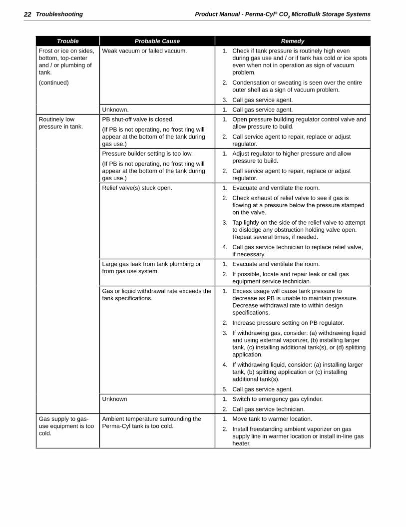
TroubleshootingThe following table is arranged in a Trouble/Probable Cause/Remedy format. The probable causes for specific problems are listed in descending order of significance. That is, check out the first cause listed before proceeding to the next.
22 Troubleshooting Product Manual - Perma-Cyl® CO2 MicroBulk Storage Systems
Trouble Probable Cause RemedyFrost or ice on sides, bottom, top-center and / or plumbing of tank.
(continued)
Weak vacuum or failed vacuum. 1. Check if tank pressure is routinely high even during gas use and / or if tank has cold or ice spots even when not in operation as sign of vacuum problem.
2. Condensation or sweating is seen over the entire outer shell as a sign of vacuum problem.
3. Call gas service agent.Unknown. 1. Call gas service agent.
Routinely low pressure in tank.
PB shut-off valve is closed.
(If PB is not operating, no frost ring will appear at the bottom of the tank during gas use.)
1. Open pressure building regulator control valve and allow pressure to build.
2. Call service agent to repair, replace or adjust regulator.
Pressure builder setting is too low.
(If PB is not operating, no frost ring will appear at the bottom of the tank during gas use.)
1. Adjust regulator to higher pressure and allow pressure to build.
2. Call service agent to repair, replace or adjust regulator.
Relief valve(s) stuck open. 1. Evacuate and ventilate the room.
2. Check exhaust of relief valve to see if gas is flowing at a pressure below the pressure stamped on the valve.
3. Tap lightly on the side of the relief valve to attempt to dislodge any obstruction holding valve open. Repeat several times, if needed.
4. Call gas service technician to replace relief valve, if necessary.
Large gas leak from tank plumbing or from gas use system.
1. Evacuate and ventilate the room.
2. If possible, locate and repair leak or call gas equipment service technician.
Gas or liquid withdrawal rate exceeds the tank specifications.
1. Excess usage will cause tank pressure to decrease as PB is unable to maintain pressure. Decrease withdrawal rate to within design specifications.
2. Increase pressure setting on PB regulator.
3. If withdrawing gas, consider: (a) withdrawing liquid and using external vaporizer, (b) installing larger tank, (c) installing additional tank(s), or (d) splitting application.
4. If withdrawing liquid, consider: (a) installing larger tank, (b) splitting application or (c) installing additional tank(s).
5. Call gas service agent.Unknown 1. Switch to emergency gas cylinder.
2. Call gas service technician.Gas supply to gas-use equipment is too cold.
Ambient temperature surrounding the Perma-Cyl tank is too cold.
1. Move tank to warmer location.
2. Install freestanding ambient vaporizer on gas supply line in warmer location or install in-line gas heater.

23TroubleshootingProduct Manual - Perma-Cyl® CO2 MicroBulk Storage Systems
Trouble Probable Cause RemedyGas supply to gas-use equipment is too cold. (continued)
Gas withdrawal rate from Perma-Cyl tank exceeds the capacity of tank’s ambient vaporizer.
1. Reduce gas withdrawal rate to within specified parameters.
2. Install freestanding ambient vaporizer on gas supply line in warm location or install in-line heated vaporizer on gas supply circuit.
3. Install larger tank with greater withdrawal rate capacity.
Routinely high tank pressure.
Normal when little or no gas has been used for several days.
1. None - Routine use of gas will automatically reduce the tank pressure.
2. Gas usage must exceed NER of tank, if not, contact gas supplier for different tank model.
Economizer function on regulator is malfunctioning.
1. If tank is in a mixer application and the usage is low, consider drawing gas off the vent line, as the economizer will not work completely in non-consistent draws.
2. Call gas service technician to clean, repair, or replace regulator.
Tank is over-filled 1. If tank is filled to or beyond proper fill level, pressure builds very rapidly and relief valve may open.
2. Use gas or liquid as soon as possible to reduce tank contents.
3. Vent tank until no liquid is coming out the vent valve.
4. Follow liquid withdrawal procedures to transfer excess contents into a second tank and eliminate the over-fill situation. Avoid hazards of contact with cryogenic liquids, excess gas concentrations, or high pressure.
Pressure building function on regulator is set too high or regulator is malfunctioning.
1. Reduce pressure setting by turning adjustment knob counter-clockwise to the desired pressure setting and continuing normal gas use until pressure drops.
2. Close PB isolation valve and carefully observe pressure to ensure tank pressure does not drop too low during use.
3. Call gas service technician to adjust PB regulator.Weak or failed vacuum. 1. Observe if condensation and / or frost are present
even during periods of non-use as possible sign of vacuum problem.
2. Call gas service technician.Unknown. 1. Call gas service technician.
Hissing sounds or evidence of gas leaking near tank, gas lines, or gas-use equipment.
Normal for short periods of time from some regulators and relief valves.
1. Evacuate and ventilate room or area, if necessary.
2. If possible, observe leak. If leak is not large, does not last long, does not occur frequently and is in well-ventilated area, no action may be needed. If in doubt, call appropriate equipment service technician.
3. If above combined conditions do not exist, call equipment service technician and observe “Safety” precautions.

24 Troubleshooting Product Manual - Perma-Cyl® CO2 MicroBulk Storage Systems
Trouble Probable Cause RemedyHissing sounds or evidence of gas leaking near tank, gas lines, or gas-use equipment. (continued)
Large leaks, leaks from elsewhere in the system, sustained leaks, or frequent leaks (not normal)
1. Evacuate all personnel from affected areas. Ventilate room / area.
2. If possible, locate the leak and repair it or call gas service or gas-use equipment service technician.
High gas usage. Unrecognized increase in actual gas use. 1. None for Perma-Cyl tank or gas supplier
2. Gas user to determine reason for increase in gas use.
Leak in gas supply line or network or in gas-use equipment or tank plumbing, e.g. relief valve.
1. Evacuate and ventilate room, if necessary.
2. If possible, locate and repair leak or call gas-use equipment service agent.
3. User to check tank for frost / leaks before operations.
Tank pressure routinely too high and venting.
1. See troubleshooting section on routinely high tank pressure.
High flash or vaporization losses in liquid use application due to high pressure / temperature liquid in tank.
1. Vent tank to approximately 25 psi. Follow safety procedures.
2. In future only refill the Perma-Cyl tank with low-pressure cryogenic product.
Error in gas delivery or supplier invoice. 1. Check gas usage history / pattern against supplier invoices.
2. Call gas supplier, if necessary.Perma-Cyl tank cannot be filled.
Perma-Cyl tank is full. 1. NoneFill line is blocked or inoperative. 1. Check for obstructions in the fill line. Clear if
necessary.
2. Gently tap on check valve to assure proper operation.
3. Call gas service technician.Not enough differential in pressures between Perma-Cyl tank and delivery vehicle
1. Vent down Perma-Cyl tank to pressure is at least 50 psig lower than delivery vehicle.
Vacuum pump-out port and / or vacuum plug are open or damaged.
Pump-out plug or port have been damaged or tampered with.
1. If possible, transfer any remaining contents to another tank.
2. Call gas service technician to replace and repair tank.
Inner vacuum space leak has dislodged safety pump-out plug.
1. If possible, transfer any remaining contents to another tank.
2. Call gas service technician to replace and repair tank.
Warning! Use only parts which are cleaned and approved for oxygen service. Chart recommends the use of only Chart approved parts.

25Product Manual - Perma-Cyl® CO2 MicroBulk Storage Systems
Dimensions & Weights 2000 CO2 HP 3000 CO2 HPRelief Valve Setting / MAWP 350 psig 24.1 barg 350 psig 24.1 bargOverall Height 116 in 2946 mm 122 in 3099 mmWidth with Pallet Base 53 in 1346 mm 60.5 in 1537 mmLength with Pallet Base 67 in 1702 mm 75.5 in 1918 mmTank Diameter 48 in 1219 mm 58 in 1473 mmTare Weight* 2950 lbs 1338 kg 3300 lbs 1497 kgCapacitiesGross Volume 539.5 gal 2042 liters 769 gal 2911 litersNet Volume 513.9 gal 1945 liters 715 gal 2707 litersGaseous Volume** 38,048 scf 1000 Nm3 52,954 scf 1390 Nm3
Full Weight** 7303 lbs 3313 kg 9357 lbs 4244 kgPerformanceNormal Evaporation Rate (% per day)*** .3%Gas Supply Rate @ 300 psig 500 scfh 14.2 Nm3H 500 scfh 14.2 Nm3H
57 lbs/hr 26 kg/hr 57 lbs/hr 26 kg/hrGas Supply Rate @ 300 psig**** 2600 scfh 73.8 Nm3H 2600 scfh 73.8 Nm3H
300 lbs/hr 136 kg/hr 300 lbs/hr 136 kg/hrConstructionDesign & Manufacturing Code ASME Section VIII Div. 1Outer Vessel Type 304 SSPallet Base Galvanized Carbon Steel
Footnotes: Specifications subject to change without prior notice.*Weights include lab base.**Values are based on net capacity at 1 atmosphere and 70°F.***Values are based on gross volume.****External vaporizer required.
Specifications


27Product Manual - Perma-Cyl® CO2 MicroBulk Storage Systems
Illustrations & Parts Listing
2000/3000 HP CO2 Parts ListingItem Qty PN Description Mfg PN ManufacturerFC-1 1 10582833 CONN BRS QK MALE FILL FTG SNAP-TITE 6660-13CV-1 1 20957011 FILL CHECK VALVE 1” X 1” FPT CV-1003B-T-3 GenerantLl-1 1 20910598 CYL-TEL GEN 5 N/A ChartLl-1 1 20909590 DIFF PG 4-1/2” DIAL 0-100”H2O 1/4NPT 52718757 WikaPI-1 1 20827654 PG 2” DIAL 0-600PSI/BAR 1/8MPT PANEL MNT 52553914 WikaR-1 1 11388741 REGULATOR .500NPT @ 150 PSI FRM-2 51-50 PentairR-1 1 20818549 REGULATOR .500NPT @ 325 PSI E-1 PentairR-2 1 11779806 REGULATOR .500NPT @ 125 PSI E-1 PentairR-2 1 11690211 REGULATOR .500NPT @ 300 PSI E-1 Pentair
RV-1 2 20599868 RV BRS 350 PSI 1/2 MPT (ASME) C19434TP350 RegoRV-2 2 11708451 RV BRS 450 PSI 1/2 MPT PRV94433TP450 RegoRV-3 1 1812702 RV BRS 550 PSI 1/4 MPT PRV94432TP550 RegoRV-4 1 1812702 RV BRS 550 PSI 1/4 MPT PRV94432TP550 RegoRV-5 1 1812702 RV BRS 550 PSI 1/4 MPT PRV94432TP550 RegoV-1 1 20888626 VALVE BALL SS 1/2 NPT (GAS USE) 00129FB3600XTB 31.3 JamesburyV-2 1 20888626 VALVE BALL SS 1/2 NPT (ECON OUTLET) 00129FB3600XTB 31.3 JamesburyV-3 1 20888626 VALVE BALL SS 1/2 NPT (LIQUID) 00129FB3600XTB 31.3 JamesburyV-4 1 11773885 VALVE BALL DIV SS 1/2 NPT (SAFETY) 76-603-57 B31.3 ApolloV-5 1 12930205 VALVE BALL SS 1FPT (VENT/FULL TRYCOCK) A-EW0013600XTD NON JamesburyV-6 1 20888626 VALVE BALL SS 1/2 NPT (ECON INLET) 00129FB3600XTB 31.3 JamesburyV-7 1 20683719 VALVE 4 WAY 1/4 FPT (PRESSURE/LEVEL) B-43ZTF2-WL8 SwagelokV-8 1 20888626 VALVE BALL SS 1/2 NPT (PB INLET) 00129FB3600XTB 31.3 JamesburyV-9 1 20888626 VALVE BALL SS 1/2 NPT (PB OUTLET) 00129FB3600XTB 31.3 JamesburyV-10 2 10907239 NEEDLE VALVE BRS 1/4 NPT (SAFETY DRAIN) CMM250A B31.3 Rego

28 Illustrations & Parts Listing Product Manual - Perma-Cyl® CO2 MicroBulk Storage Systems
2000/3000 HP CO2 Top View
Model DimensionsModel Dim A Dim B Dim C Dim D Dim E Dim F
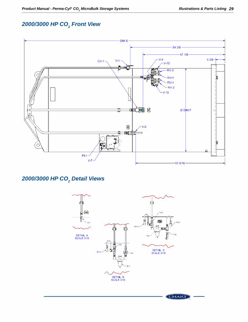
Perma-Cyl 2000 CO2 52 5/8 48 5/8 66 5/8 62 5/8 115 1/4 48Perma-Cyl 3000 CO2 60 1/2 56 1/2 75 1/2 71 1/2 121 1/4 58
29Illustrations & Parts ListingProduct Manual - Perma-Cyl® CO2 MicroBulk Storage Systems
2000/3000 HP CO2 Front View
2000/3000 HP CO2 Detail Views
