performance evaluation of iec 61850-90-5 over a non...
TRANSCRIPT

UPTEC IT 17 022
Examensarbete 30 hpOktober 2017
Performance Evaluation of IEC 61850-90-5 Over a Non-Commercial 4G LTE Network
Linus Eriksson
Institutionen för informationsteknologiDepartment of Information Technology
Teknisk- naturvetenskaplig fakultet UTH-enheten Besöksadress: Ångströmlaboratoriet Lägerhyddsvägen 1 Hus 4, Plan 0 Postadress: Box 536 751 21 Uppsala Telefon: 018 – 471 30 03 Telefax: 018 – 471 30 00 Hemsida: http://www.teknat.uu.se/student
Abstract
Performance Evaluation of IEC 61850-90-5 Over aNon-Commercial 4G LTE Network
Linus Eriksson
Old electrical power grids with unidirectional power flow are transforming intoenhanced smart grid systems with bidirectional power flow. Advancements incommunication infrastructure can offer new ways on how communication can beutilized within the grid. The standardized communication protocol IEC 61850 definesdata models and services designed for communication within a substation. Smart gridapplications will require communication over wider areas and between substations.The IEC 61850-90-5 addition to the standard defines how data can be sent overwider areas by utilizing Internet protocol, which is necessary if public communicationnetworks such as 4G long term evolution is used.
This thesis evaluates the applicability of the IEC 61850-90-5 protocol when used overa non-commercial 4G LTE network. A prototype that emulates an intelligentelectronic device was derived from an IEC 61850-90-5 open source project and wasused transmit and receive data over the network. To evaluate the applicability of theIEC 61850-90-5 stack and the performance of the non-commercial 4G LTE networkdifferent metrics such as reliability, availability, latency, and throughput was evaluated.
The overall result is promising and indicates that the IEC 61850-90-5 protocol incombination with 4G LTE would be suitable for most applications within the smartgrid. It is concluded that cellular technologies such as 4G LTE will play an importantrole for smart grid applications, even though it does not fulfill the most stringentapplication requirements. The IEC 61850-90-5 protocol will be a key component insmart grids since it enables routing of standardized GOOSE and SV messages in IPpacket format, which is needed when using commercial networks such as 4G LTE.
Tryckt av: Reprocentralen ITCUPTEC ** ***Examinator: Lars-Åke NordénÄmnesgranskare: Tomas OlossonHandledare: Gargi Bag

Acknowledgements
This report describes a master thesis project conducted at ABB Corporate Re-search in Västerås, Sweden.
I would like to begin this thesis report by thanking Mr. Rajendra Bogati whowas a part of this project and whom I worked closely with.
I would also like to thank ABB Corporate Research for giving me the opportu-nity to work with an interesting project.
Many thanks to my supervisor Gargi Bag from ABB Corporate Research forthe help, support, and feedback throughout this project.
Last but not least I want to thank my reviewer, Tomas Olofsson from UppsalaUniversity, for your support and guidance throughout the project.
Linus ErikssonUppsala, 2017

AcronymsAMI Advanced Metering Infrastructure
APDU Application Protocol Data Unit
ACSI Abstract Communication Service Interface
ASDU Application Service Data Unit
BAN Building Area Network
BER Basic Encoding Rule
CDC Common Data Class
CDF Cumulative Distribution Function
DAS Data Acquisition Systems
DHCP Dynamic Host Configuration Protocol
FAN Field Area Network
GOOSE Generic Object Oriented Substation Event
GSE Generic Substation Event
GSSE Generic Substation State Event
HAN Home Area Network
IAN Industrial Area Network
IEC International Electrotechnical Commission
IED Intelligent Electronic Device
IP Internet Protocol
LAN Local Area Network
LTE Long Term Evolution
MAC Medium Access Control
MMS Manufacturing Message Specification
NAN Neighborhood Area Network
NTP Network Time Protocol
PDC Phasor Data Concentrators
PDU Protocol Data Units
PMU Phasor Measurement Unit
QoS Quality of Service
ii

ROCOF Rate Of Change Of Frequency
SAS Substation Automation System
SCADA Supervisory Control And Data Acquisition
SCL Substation Configuration Language
SCMS Specific Communication Service Mapping
SPDU Session Protocol Data Unit
SV Sampled Value
SVCB Sampled Value Control Block
TCP Transmission Control Protocol
TLV Tag Length Value
UCS Utility Communication Architecture
UDP User Datagram Protocol
UTC Coordinated Universal Time
VPN Virtual Private Network
WAN Wide Area Network
WAMPAC Wide Area Monitoring Protection and Control
WLAN Wireless Local Area Network
iii
Contents1 Introduction 1
1.1 Purpose and Goal . . . . . . . . . . . . . . . . . . . . . . . . . . 11.2 Scope . . . . . . . . . . . . . . . . . . . . . . . . . . . . . . . . . 21.3 Related Work . . . . . . . . . . . . . . . . . . . . . . . . . . . . . 3
1.3.1 Performance of LTE for Smart Grid Communications . . 31.3.2 Performance Evaluation of IEC 61850 under Wireless Com-
munication Networks . . . . . . . . . . . . . . . . . . . . . 31.3.3 Performance evaluation of smart grid communications via
network simulation version 3 . . . . . . . . . . . . . . . . 41.3.4 Opportunities and Challenges of Wireless Communication
Technologies for Smart Grid Applications . . . . . . . . . 51.4 Disposition . . . . . . . . . . . . . . . . . . . . . . . . . . . . . . 5
2 Background 62.1 Power Systems . . . . . . . . . . . . . . . . . . . . . . . . . . . . 6
2.1.1 Communication in Power System . . . . . . . . . . . . . . 62.2 Smart Grid . . . . . . . . . . . . . . . . . . . . . . . . . . . . . . 72.3 IEC 61850 Standard . . . . . . . . . . . . . . . . . . . . . . . . . 8
2.3.1 IEC 61850 Data Modeling . . . . . . . . . . . . . . . . . . 102.3.2 Abstract Communication Service Interface . . . . . . . . 122.3.3 Generic Substation Event . . . . . . . . . . . . . . . . . . 122.3.4 Sampled Values . . . . . . . . . . . . . . . . . . . . . . . . 13
2.4 IEEE C37.118.1 . . . . . . . . . . . . . . . . . . . . . . . . . . . . 132.5 IEEE C37.118.2 . . . . . . . . . . . . . . . . . . . . . . . . . . . . 14
3 IEC 61850-90-5 153.1 Overview . . . . . . . . . . . . . . . . . . . . . . . . . . . . . . . 153.2 Data modeling . . . . . . . . . . . . . . . . . . . . . . . . . . . . 153.3 Data Encoding . . . . . . . . . . . . . . . . . . . . . . . . . . . . 173.4 R-GOOSE and R-SV . . . . . . . . . . . . . . . . . . . . . . . . . 183.5 Communication Requirements . . . . . . . . . . . . . . . . . . . . 19
4 Implementation and Result 214.1 Test Methodology . . . . . . . . . . . . . . . . . . . . . . . . . . 21
4.1.1 Test Environment Setup . . . . . . . . . . . . . . . . . . . 214.1.2 Modification of the IEC 61850-90-5 Open Source . . . . . 224.1.3 Setup Overview . . . . . . . . . . . . . . . . . . . . . . . . 224.1.4 Configuration Parameters . . . . . . . . . . . . . . . . . . 234.1.5 Time Synchronization . . . . . . . . . . . . . . . . . . . . 244.1.6 Wireshark Captures . . . . . . . . . . . . . . . . . . . . . 254.1.7 Data Extraction and Plotting . . . . . . . . . . . . . . . . 27
4.2 Test Cases . . . . . . . . . . . . . . . . . . . . . . . . . . . . . . . 274.2.1 Availability . . . . . . . . . . . . . . . . . . . . . . . . . . 274.2.2 Throughput . . . . . . . . . . . . . . . . . . . . . . . . . . 284.2.3 Latency . . . . . . . . . . . . . . . . . . . . . . . . . . . . 284.2.4 Reliability . . . . . . . . . . . . . . . . . . . . . . . . . . . 29
4.3 Results . . . . . . . . . . . . . . . . . . . . . . . . . . . . . . . . . 294.3.1 Availability . . . . . . . . . . . . . . . . . . . . . . . . . . 29
iv
4.3.2 Throughput . . . . . . . . . . . . . . . . . . . . . . . . . . 304.3.3 Latency . . . . . . . . . . . . . . . . . . . . . . . . . . . . 314.3.4 Reliability . . . . . . . . . . . . . . . . . . . . . . . . . . . 33
5 General Discussion and Conclusion 355.1 Future Work . . . . . . . . . . . . . . . . . . . . . . . . . . . . . 36
v
List of Figures1 Traditional electric power grid [17] . . . . . . . . . . . . . . . . . 62 Data rate and communication range [21] . . . . . . . . . . . . . . 83 IEC 61850 Data Modeling [10] . . . . . . . . . . . . . . . . . . . 114 The IEC 61850 object transformed into a named MMS variable
object with a unique reference for a element in the model [19] . . 125 The structure of the IEC 61850-90-5 Session Protocol From [9] . 166 Basic Encoding Rule . . . . . . . . . . . . . . . . . . . . . . . . . 177 ANS.1 BER encoded SV APDU, from [8] . . . . . . . . . . . . . 188 Mapping of phasor measurements [16] . . . . . . . . . . . . . . . 199 Communication Requirements [9] . . . . . . . . . . . . . . . . . . 2010 Environment test setup . . . . . . . . . . . . . . . . . . . . . . . 2111 Flow chart of the test process . . . . . . . . . . . . . . . . . . . . 2312 Structure of the startup file for the application . . . . . . . . . . 2413 Time Synchronization utilizing a NTP server . . . . . . . . . . . 2514 SV packet captured in Wireshark . . . . . . . . . . . . . . . . . . 2615 The data representing three synchrophasors sent in a SV packet . 2616 The network availability measurements graphed over a period of
24 hours . . . . . . . . . . . . . . . . . . . . . . . . . . . . . . . 3017 The throughput for different transmission intervals graphed against
different packet sizes . . . . . . . . . . . . . . . . . . . . . . . . . 3118 The average latency for different packet sizes graphed against
different transmission intervals . . . . . . . . . . . . . . . . . . . 3219 CDF graphed against latency for different transmission intervals 3220 Reliability graphed against time . . . . . . . . . . . . . . . . . . . 33
vi

1 IntroductionTraditional power grids with unidirectional power flow are transforming intosmart grid systems with bidirectional power flow. Renewable sources of energyin the power grid such as wind and solar increase the need of having morecontrol, monitoring, and protection applications that serve the needs for gridautomation. At the same time as the power grid continues to evolve, communi-cation infrastructure is evolving and can offer new ways on how communicationcan be utilized within the power grid. Increased connectivity makes it possibleto connect more devices and applications to the grid. Wireless communicationtechnology offers scalability and flexibility in a cost efficient way since it reducethe need of expensive wires and installation costs.
There are several wireless technologies for both short range and long range com-munication. Cellular technologies such as the Fourth Generation (4G) can playan important role in realizing fast and reliable communication for smart gridapplications. 4G wireless systems were mainly developed for reasons such asthat it is all-Internet Protocol (IP) based system, to reduce data latencies andsignal loading and always-on user experience with flexible Quality of Service(QoS) support. The 4G systems can be accessed with different technologiessuch as Long Term Evolution (LTE) and LTE-Advanced [2].
For wireless communication to be accepted in the smart grid domain, it has tofulfill requirements related to parameters such as latency, reliability, availability,and throughput. The requirements for these parameters varies depending on thetype of application. Some applications have very stringent requirements sincefailure or anomalies in data delivery can cause severe damages. LTE, whichalready is a technology in use, covers long distances and offers high throughputand it may therefore be suitable for smart grid applications if it meet the re-quirements.
The standardized communication protocol International Electrotechnical Com-mission (IEC) 61850 offers interoperability between devices from different ven-dors and defines data models and services designed for communication withina substation. Many of the applications in a smart grid system will requirecommunication over wider areas and between substations. The IEC 61850-90-5addition to the standard defines how data can be sent over wide areas utilizingIP, which is necessary if public communication networks such as 4G LTE is used.
1.1 Purpose and GoalThe purpose of this project is to benchmark and evaluate the performance ofa non-commercial LTE network. Furthermore, to examine the readiness andapplicability of the already available IEC 61850-90-5 stack to support phasorcommunication over a wireless network.
To evaluate the performance, different metrics need to be considered such asreliability, availability, latency, and throughput. The performance evaluation ofthe non-commercial LTE network, when using the IEC 61850-90-5 stack, willgive insight on the applicability of the communication protocol when used over
1

a LTE network. Furthermore will the evaluation of the metrics, show if andwhat improvements that are needed to meet the communication requirementsgiven by different applications in the smart grid.
A prototype that emulates an Intelligent Electronic Device (IED) will be derivedfrom an IEC 61850-90-5 open source project [12]. An IED is microprocessor-based controller used within power systems for protection, control, monitoring,metering, and communication [23]. The IEC 61850-90-5 stack will be used totransmit and receive data via the non-commercial 4G LTE network. Test caseswill be derived to measure the above-mentioned metrics and the results will bepresented as a benchmark of the non-commercial LTE network when using theIEC 61850-90-5 stack.
1.2 ScopeThe scope of this thesis project is to prepare the IEC 61850-90-5 open sourcestack to exchange phasor data over the non-commercial 4G LTE network. Thiswill give indications on the readiness and applicability of the IEC 61850-90-5stack to support smart grid applications when wireless communication is used.
The following milestones have been considered in this project:
• To get an understanding of the IEC 61850 communication standard andhow it works,
• To identify the key features of IEC 61850-90-5 such as:
– how data is structured and modeled,– which parameters will be used to transmit and receive data,– what needs to be configured in order to exchange data,
• To transmit and receive IEC 61850-90-5 data over a non-commercial 4GLTE network,
• To benchmark the performance of the IEC 61850-90-5 stack when usedover the network,
• To present and evaluate the results.
To be able to finish the project within the time span of a thesis project, thescope of the project had some delimitations. The main focus was on how theIEC 61850 and IEC 61850-90-5 standard are used for communication and tomeasure the performance when using the IEC 61850-90-5 stack in a wirelessenvironment. Therefore aspects such as security was not considered.
The non-commercial 4G LTE infrastructure was provided by an external sourceand is hence not described in depth. This is a benchmark of the 4G LTE networkand no profound analysis of the outcome of the tests is presented. A thoroughanalysis of the results would be time consuming and has therefore been left forfuture work.
2
1.3 Related WorkIt has been of interest to utilize wireless communication such as 4G LTE, Wi-Fi,ZigBee etc, for communication within the smart grid for a few years. Differentstudies have been made regarding if and how the wireless communication wouldbe a feasible alternative to the wired communication.
1.3.1 Performance of LTE for Smart Grid Communications
The authors of [4] investigated whether LTE can be used in combination withIEC 61850 and Manufacturing Message Specification (MMS) to support smartmetering and remote control communication and at the same time have a de-sirable QoS. Two sets of simulations were done to verify whether the latencyand priority requirements are satisfied by their integrated LTE and IEC 61850MMS solution, one set for remote control communication services and one setfor smart metering services.
The remote control communication service experiment was based on a MMSclient/server architecture combined with the LTE communication system. Fur-thermore is a Medium Access Control (MAC) scheduling mechanism used toprioritize the IEC 61850-based traffic over the generated LTE background traf-fic mix. The traffic mixes are used as the percentage of traffic such as 80/20 and60/40 to imitate background traffic, i.e. 80/20 indicates 20 percent backgroundtraffic. Two MAC scheduling mechanisms are supported; Round Robin (RR)and Priority-aware Round Robin (PrioRR).
The authors observed that the throughput results are approximately equal forthe scenarios that use RR or PrioRR MAC scheduler. Furthermore, it can beobserved that the average delay is almost the same for RR and PrioRR sched-uler, which also is true for the packet loss ratio.
The main difference between the remote control communication service experi-ment and the smart meter service experiment is that in the latter, smart meterentity and MDMS Host entity is used instead of MMS client/server. Also, onlythe RR MAC scheduler was used for the experiment. The smart metering exper-iments showed that average delay increased when the total traffic load increased,which was expected.
The simulation results indicated that LTE can be integrated with IEC 61850MMS to satisfy the performance requirements on smart metering and remotecontrol communication services in smart grid distribution networks.
1.3.2 Performance Evaluation of IEC 61850 under Wireless Com-munication Networks
In the paper [20] the authors present the modeling and simulation of an IED inan IEC 61850 Substation Automation System (SAS) under wireless or hybridnetworks for three type of messages, Generic Object Oriented Substation Event
3

(GOOSE), Sampled Value (SV), and Interbay trip messages.
The SAS network was modeled using a network modeling tool called OPNETand different scenarios were simulated. The data messages are sent at varioussampling rates which are 960 samples/sec, 1920 samples/sec and 4800 sam-ples/sec. The wireless network consists of different IEDs such as IEDs for pro-tection and control, measurement units, and circuit breakers.
To compare the wireless and hybrid network with a wired network, the same sce-nario was simulated with the same sampling rates. The authors conclude thatwhen circuit breakers were connected wireless, trip messages had high delays.Furthermore, it is concluded that the wireless network provides lower delays andhigh throughput for simulated scenarios having data rate of 54Mbps, which theauthors recommend for wireless SAS networks.
1.3.3 Performance evaluation of smart grid communications via net-work simulation version 3
Other studies conducted in [18], investigated the performance of ZigBee underdifferent setups. Moreover, the authors also investigate the performance of LTEand Wi-Fi. To measure the performance of data communication in a smart gridNeighborhood Area Network (NAN), a network simulation tool called networksimulation version 3 were used.
The investigation of smart grid communication between Data ConcentratorUnits (DCU)s and Advanced Metering Infrastructure (AMI) separates the sim-ulation results into two sections. Firstly, the maximum distance for data trans-mission between DCU and AMI devices is compared for three wireless technolo-gies. Secondly, the performance of ZigBee in different smart grid situations.
Moreover, The authors describe smart grid technologies and communicationframeworks such as DLMS/COSEM which is a protocol that can be utilized asan interface to gather power consumption data between DCUs and AMIs. Fur-ther the authors discuss ZigBee, Wi-Fi and LTE communication technologies inNAN networks.
The authors have added a DLMS/COSEM modules to the NS version 3.22 tosuit their project. The results of the simulations, with DLMS/COSEM proto-col, shows that the transmission length of LTE is greater than the transmissionlength of ZigBee and Wi-Fi. The remainder of the paper mainly focuses onexperiments of various ZigBee simulations. The results from the ZigBee simula-tions shows that the appropriate distance between DCU and AMI is 100 metersand the maximum AMI density, when located nearly together, is 145 nodes.
4

1.3.4 Opportunities and Challenges of Wireless Communication Tech-nologies for Smart Grid Applications
The authors of the paper [22] present various smart grid applications that utilizestandardized communication technologies such as Wireless Local Area Network(WLAN), ZigBee and cellular 3G/4G. Furthermore are challenges related tovarious wireless technologies discussed.
It is stated that the advantage of cellular technologies is that, to some extent,the current cellular infrastructure can be used and that the evolution of 3G/4Gcellular technology has improved the QoS as well as the data rates.
The Supervisory Control And Data Acquisition (SCADA) interface for remotedistribution substation is a smart grid application that can utilize cellular tech-nology such as 4G due to the availability of cellular coverage. It is concludedthat wireless technology offers many advantages over wired technologies such aslow installation cost, mobility, remote location coverage, and rapid installation.
1.4 DispositionThe rest of the report is organized as follows:
In section 2, a background to the subject is given and key features of the tech-nology is described. This is followed by section 3 with a presentation of IEC61850-90-5, the theory behind the technology and description of the data struc-ture. Section 4 provides a description of the test methodology, the test setup,and the results are presented and evaluated. In section 5, future work is pre-sented and the project as a whole is discussed, including the results and thequality of the results.
5

2 Background
2.1 Power SystemsAn electric power system is a network that consists of electrical machines, linesand ways to supply electricity to consumers. When such systems are intercon-nected and the transmission of energy can be done over longer distances it isknown as a power network, or a grid [1]. The power system delivery grid havemany times been referred to as the greatest and most complex machine built inthe human civilization [3].
The grid operates the same way it did almost 100 years ago, where the energyis provided to the consumers from a centralized power plant [1]. At the sametime as the grid is getting older and outdated, the consumption of electricity issteadily rising [24].
Figure 1: Traditional electric power grid [17]
Figure 1 illustrates a simplified traditional one-way power grid. As can be seenin the figure, the electric power is generated in power plants such as thermalor nuclear. The voltage levels are increased in the transmission substations totransport the electric power via high-voltage transmission lines over long dis-tances closer to the consumers. In the distribution substations the voltage levelsare reduced and is delivered to consumers via distribution lines [17].
2.1.1 Communication in Power System
Communication in real-time systems, such as in power systems, have alwaysbeen important since it is used to control the actual system. In the 1930’s,telephone lines were used in order to communicate between substations and thecontrol center. The telephone lines were used to communicate if the dispatchoperators should perform switch operations in the substation or to give readingsof line loadings to the control center. Decades later, in the 1960’s, automatedsystems were used to collect data from substations. These systems was calledData Acquisition Systems (DAS) and had to be designed for low-bandwidth dueto bandwidth limitations [19].
As technology evolved, bandwidth was no longer a major concern and newstandards of how to communicate were needed. In 1988 the Utility Communi-cation Architecture (UCA) was developed, which aimed to suit the International
6

Standards Organization (ISO) model for communication, named Open SystemInterconnect (OSI) [19].
Later, IEC presented the IEC 61850 standard, which is based on the conceptsfrom UCA [19]. The standard is named IEC 61850 - Communication Networksand Systems in Substations. The goal of IEC 61850 is to be an internationalstandard for communication within substations.
The introduction of enhanced SCADA systems offers new ways of controlling andmonitoring the transmission substation equipment. The substation equipmentcould be controlled from operation centers which offered increased operationalefficiency [17] and hence made the power grid more controllable, customizable,efficient, and smart.
2.2 Smart GridThe smart grid relies on real-time exchange of measurements and control databetween devices in homes and businesses, in the transmission and distributiongrid, and in substations and control centers. This demands that the communi-cation network is reliable, secure and high performing [17].
Bi-directional communication technology is utilized within the smart grid sys-tem with multiple functions such as automatic electrical management and re-newable management, hence the smart grid is highly efficient and overall reducesthe electrical loss during transmission [18].
The smart grid is evolving for reasons such as the need for clean energy, energythat can be deployed in large scale, renewable energy sources and environmen-tal reasons. As the smart grid technology continues to grow, new elements,functions, and application areas are introduced as presented in [17] and shownbelow:
• the deployment of renewable sources of energy throughout the grid,
• the deployment of AMI, also known as smart meters, at consumer loca-tions,
• the extended SCADA connectivity,
• the deployment of time stamped phasors, also known as synchrophasor,throughout the transmission grid.
A smart grid architecture generally consists of five layers; a power system layer,a control layer, a communication layer, a security layer and an application layer.In a smart grid system, the communication layer consists of three types of net-works separated by coverage range and data rate as illustrated in figure 2 [18][21].
7

Figure 2: Data rate and communication range [21]
The Home Area Network (HAN), Building Area Network (BAN), and IndustrialArea Network (IAN) are networks that have less coverage range and data ratesand is typically used within customer premises. NAN and Field Area Network(FAN) is used when data is transmitted from a larger number of devices andlong distances, thus require better coverage range and higher data rates. Appli-cations for Wide Area Network (WAN), such as wide-area control, monitoring,and protection typically requires transmission of more data over longer distances[21].
Depending on system requirements such as reliability, latency, bandwidth, andthroughput, different communication technologies may be used to connect thenetworks [18]. Moreover, the different requirements for the communication net-works depend on parameters such as data rate and communication range asshown in 2 [21].
The most stringent communication requirements are generally found in WANcompared to HAN/BAN/IAN and NAN networks. WAN typically supportsreal-time monitoring, control and protection applications and response timesfor these applications should be in the range of milliseconds to minutes. More-over should the WAN reliability for the communication system be high, e.g. >99.9 % [21].
2.3 IEC 61850 StandardThe first publication of the IEC 61850 standards was released between 2002and 2005. The standard was the result of nearly ten years of work done withinIEEE/EPRI on UCA and within the working group called "Substation Controland Protection Interfaces" of IEC Technical Committee 57. The scope of thework was to standardize the communication in substation automation systems[10].
The first release mainly focused on protection, control, and monitoring and wasdivided into 10 parts as shown in table 1 [10]. New additions and updated ver-sions of the standard is continuously released but are not included in the table
8

below.
The IEC 61850 standard provides models for power system devices on how toorganize data, configure objects and map them to appropriate protocols to keepdevices consistent and interoperable. Interoperability is obtained by having lessor no restrictions in the hardware logic [15].
Part TitleIEC 61850-1 Introduction and overviewIEC 61850-2 Glossary of termsIEC 61850-3 General requirementsIEC 61850-4 System and project managementIEC 61850-5 Communication requirements for functions and device mod-
elsIEC 61850-6 Communication description language for communication in
electrical substations related to IEDsIEC 61850-7 Basic communication structure for substation and feeder
equipmentIEC 61850-7.1
Principles and models
IEC 61850-7.2
Abstract communication service interface (ACSI)
IEC 61850-7.3
System and project management
IEC 61850-7.4
Compatible logical node classes and data classes
IEC 61850-8 Specific communication service mapping (SCSM)IEC 61850-8.1
Mapping to MMS (ISO 95066-1 and ISO 9506-2) and toISO/IEC 8802-3
IEC 61850-9 Specific communication service mapping (SCSM)IEC 61850-9.1
Sampled values over serial unidirectional multidrop pointto point link
IEC 61850-9.2
Sampled values over ISO/IEC 8802-3
IEC 61850-10
Conformance testing
Table 1: The 10 parts of the first release of the IEC 61850 standard
Part 1 of the IEC 61850 standard gives an introduction and a general overviewof the complete standard. The standard is based on data objects that are relatedto the needs of the electrical power industry. Furthermore is the communica-tion profile is based on existing IEC/IEEE/ISO/OSI communication standards,if possible [10].
Part 3, 4 and 5 describes the general requirements for using IEC 61850 for com-munication within substations. These requirements are the foundation of theidentification of what services and data models that are needed, such as physicallayers, data link, and network [19].
9

Part 6 of the standard gives an overview of the system engineering process andspecify the System Configuration Language (SCL). SCL is a way of describ-ing communication that is related to IED configuration and parameters amongother things [10].
Part 7 of the IEC 61850 standard is divided into four subparts. The first partdescribes the basic architecture for the communication structure between dif-ferent devices [7]. Part 7-2 of the IEC 61850 standard defines the AbstractCommunication Service Interface (ACSI) [6]. The abstraction makes it possibleto map the standardized data object and services to protocols that meet therequirements [19].
Part 8-1 defines a method on how to exchange data by mapping ACSI to MMSfor data that is both time-critical and non-time-critical [5].
Part 9-2 defines Specific Communication Service Mapping (SCSM) for the trans-mission of SV between sensors and IEDs as specified by the ACSI in IEC 61850-7-2 [8].
Part 10 describes how to test the conformance of the protocol definitions andconstraints that are defined in the standard [19].
2.3.1 IEC 61850 Data Modeling
The IEC 61850 standard models the common information from real devices byusing abstract models. Figure 3 illustrates the hierarchical structure of the datamodel. The functions of the application are decomposed to smaller entitieswhich are used for the information exchange within the system. As can be seenfrom figure 3, the hierarchical model consist of five layers from the physical de-vice to the smallest object, which is the data attribute.
10

Figure 3: IEC 61850 Data Modeling [10]
• Physical DeviceThe first layer of the data model is a real device or a physical device, forexample an IED. The physical device is connected to the network and istypically defined by its network address. Within the physical device, thereare one or more entries of logical devices [19][10].
• Logical DeviceThe second layer of the data model is the logical devices, which usuallyis a group of functions to support some power system function such asmeasurement or protection [10]. Within each logical device, there can beone or more logical nodes.
• Logical NodeA logical node is the smallest entity of the application and representsspecific functions. The naming convention is for example that all logicalnodes for metering and measurement begin with the letter M. Further-more, if there are two measurements from two different sources, they needto be differentiated. The logical nodes for these measurement units wouldtypically be named MMXU1 and MMXU2 respectively. Each logical nodecontains one or more elements of data [19].
• Data ObjectWithin the logical nodes, the data is contained. The data object is basedon the information and functionality of the logical node, the data maycontain information such as the position of the device.
• Data Attribute
11

Each data attribute is a Common Data Class (CDC) that describes thetype and structure of that data, there is CDCs for a variety of data, suchas status information and measured information. The CDCs is groupedinto categories, a set of Functional Constraints (FC) such as status (ST)as shown in figure 4 [19].
Figure 4: The IEC 61850 object transformed into a named MMS variable objectwith a unique reference for a element in the model [19]
2.3.2 Abstract Communication Service Interface
The ACSI defined in IEC 61850-7-2 is a standardized way of describing devices ina power system. This service interface makes it possible for IEDs to use identicalstructures to represent data that is related to functions of the power system [19].
The ACSI service provides a virtual interface that gives access to real devicesand real data and the interface can be used to describe the behavior of devices.Furthermore, the devices can be accessed from other devices such as SCADA orother maintenance systems [6].
The IEC 61850 standard provides the following types of communication mod-els for compatible information exchange among components of a power utilityautomation system, Client/Server communication service model, GOOSE, SV,and Generic Substation State Event (GSSE) [10].
The abstract services and objects are mapped within a SCSM, which is definedin part 8-1 and 9-2 of the IEC 61850 standard for GOOSE and SV respectively[10].
2.3.3 Generic Substation Event
The Generic Substation Event (GSE) model, described in [6], is a model thatmakes it possible to distribute input and output values in a SAS in a fast andreliable manner. The model defines two control classes and also the structureof two message formates
12

• Generic Object Oriented Substation Event (GOOSE) - Supports the ex-change of common data organized by a data-set,
• Generic Substation State Event (GSSE) - Capable to transfer state changeinformation.
In order to exchange information, a publisher and subscriber mechanism is used.Basically the publisher writes the values to a transmission buffer. The valuesare sent to the receivers reception buffer and the receiver reads the values fromthe reception buffer.
The reception buffer at the subscriber side is updated by the communicationsystem. The procedure of the corresponding buffer, the transmission buffer atthe publisher side, is controlled by a generic substation event control class [6].
2.3.4 Sampled Values
The model for transmission of SV described in [6], is a model which makes itpossible to transmit SV in a time controlled way. To exchange SV information,a publisher and subscriber mechanism is used.
A publisher writes data in a local buffer, the transmission buffer. The datain the transmission buffer is sent to the local buffer at the receiving side, thereception buffer, then the receiver reads the values from the local buffer at thereceiving side.
There is a need to add a time stamp so that the receiver can examine thetimeliness of the values. Furthermore, there is a need for a Sampled Value Con-trol Block (SVCB) on the publisher side to control this procedure. There aretwo different methods for exchange of SV depending on the number of receivers.If it is one receiver unicast are used and for more receivers multicast are used [6].
2.4 IEEE C37.118.1The standard C37.118.1 presented by IEEE defines the concept of synchronizedphasors, also known as synchrophasors. The standard also defines frequencyand Rate of Change of Frequency (ROCOF) measurements, and methods andrequirements for how the measurements can be verified. In an AC power sys-tems analysis, phasors that represent the sinusoidal signals can be used [13].
The definition of a sinusoidal waveform is given by:
x(t) = Xmcos(ωt+ φ) (1)
which can be represented as a phasor:
X = (Xm/√
2)ejφ
= (Xm/√
2)(cosφ+ jsinφ)
= Xr + jXi
(2)
13

In equation (2), the magnitude of the phasor is the root-mean-square value,Xm/√
2, and the values of Xr and Xi are the real and imaginary parts of a com-plex value in rectangular components. The phasor is defined for the angularfrequency ω and when compared to other phasors, the time scale and frequencymust be the same.
The definition of a synchrophasor representation of x(t) in equation (1) is thevalue X in (2). The value of φ is the instantaneous phase angle relative to acosine function when the system frequency is synchronized to UTC [13].
A Phasor Measurement Unit (PMU) can be a function within an IED and isdescribed in the IEEE C37.118.1 standard as a device that is used to producesynchrophasors and also frequency and ROCOF estimates. The estimations aredone from the voltage and/or current signals and a time synchronized signal[13].
2.5 IEEE C37.118.2The standard C.37.118.2 describes how synchrophasor measurement data canbe exchanged between power system equipment. The standard also describesdata formats for communication in real-time. Communication can be betweenPMUs, Phasor Data Concentrators (PDCs) and other applications [14].
The UTC time, that corresponds to the time when the synchrophasor measure-ment was done shall be tagged to the actual measurement, the tag shall consistof three numbers [14]:
• the second of century, seconds since UTC midnight of January 1, 1970,
• the fraction of a second,
• the time quality.
The PDC defined in IEEE C37.118.2 is a part of the communication network.The PDC is fed with synchrophasors from PMUs or other PDCs and the datais sorted by the time tag [14]. The PMU can be a stand alone function or afunction within an IED.
14

3 IEC 61850-90-5The IEC 61850-90-5 protocol defines how IP can be utilized to send data overWAN in a way that is compliant with the IEC 61850 standard. The use of IP isnecessary if the data is transmitted over a public communication network suchas 4G LTE.
3.1 OverviewThe synchrophasor measurements and calculations done by the PMUs that aredefined in IEEE C37.118.1 is considered useful to estimate the condition ofan electrical power network. Therefore, it is desired to have a communicationmechanism that is compliant with the IEC 61850 concept.
The scope of the IEC 61850-90-5 part of the IEC 61850 standard is to provide away of sending and receiving synchrophasors information between PMUs, PDCs,Wide Area Monitoring Protection and Control (WAMPAC) and between con-trol center application in a way that is compatible with IEC 61850. The IEC61850-90-5 standard also provides a way to route the IEC 61850-8-1 GOOSEand IEC 61850-9-2 SV packets. These packets can be used to transport syn-chrophasor information as well as general IEC 61850 data [9].
Applications that utilize synchrophasors are often separated by large distances.When the applications need to send data over long distances, IP can be utilized.The use of IP gives the ability to route the data between different networks overany arbitrary distance. Both Transmission Control Protocol (TCP) and UserDatagram Protocol (UDP) can be used for streaming the data [9].
3.2 Data modelingWhen describing a system as an IEC 61850 system, both the client and serverneed to be modeled as logical nodes within an IED [9]. The data model anddecoding/encoding of the data gives insight on how the data is structured andused.
15

Figure 5: The structure of the IEC 61850-90-5 Session Protocol From [9]
The structure of the IEC 61850-90-5 session protocol is shown in figure 5 and isstructured to accommodate GOOSE and SV messages in an IP packet. As canbe seen in 5, the general format consists of 3 major parts, the Session Identifier(SI), the session header, and the session user information. The hexadecimalvalues in the SI is used for encoding and decoding, which is explained and ex-emplified in section 3.3.
SI is a one byte length which covers the length of the parameter for the sessionheader.
• Session Identifier
– The hexadecimal SI value A0 is used for Tunneled GOOSE and SVpackets
– The hexadecimal SI value A1 is used for Session Protocol Data Units(SPDU)s that contain non-tunnelled GOOSE Application ProtocolData Units (APDU)s
– The hexadecimal SI value A2 is used for SPDUs that contain non-tunnelled SV APDUs
– The hexadecimal SI value A3 is used for SPDUs that contain non-tunneled management APDUs
• Session Header
– SPDU length
– SPDU Number
– SPDU Version Number
– Security Information
16

∗ TimeofCurrentKey, time for first usage of current signature andencryption key
∗ TimetoNextKey, time before a new key is assigned for signatureand encryption
∗ SecurityAlgorithms, indicated which cipher suit and algorithmsthat are used
∗ Key ID, reference to the key currently in use
• Session User Information
– Length of the User Payload
– User Payload, representing a sequence of Tunnelled, GOOSE or SVpackets
– Signature, calculated based on values of the SecurityAlgorithm field
Within the user payload, multiple user data Protocol Data Units (PDU)s canbe sent in the same SPDU. The sequence of the values begins with a tag, as forthe SI that indicates what type of payload the session protocol is transporting[9].
• GOOSE, hexadecimal tag of value 81
• SV, hexadecimal tag of value 82
• Tunnel, hexadecimal tag of value 83
• MNGT, hexadecimal tag of value 84
3.3 Data EncodingFor decoding of GOOSE and SV, ANS.1 Basic Encoding Rules (BER) is used.The principle of the BER transfer syntax is that it is a triplet of the format Tag,Length Value (TLV) as shown in figure 6, the TLV triplet is a series of octets [8].
Figure 6: Basic Encoding Rule
A TLV triplet can contain more triplets within the value of the current triplet,making it a hierarchical structure. Figure 7 shows the functionality of ANS.1BER encoding of a SV APDU, and as can be seen the SV APDU frame contains4 concatenated Application Service Data Units (ASDU)s [8].
17

Figure 7: ANS.1 BER encoded SV APDU, from [8]
3.4 R-GOOSE and R-SVThe communication described in [9] shall satisfy WAMPAC applications thatuse synchrophasors according to IEEE C37.118.1. Communication within a sub-station is typically based on SV. Other communication such as communicationfor event data can, depending on the time constraints, be communicated viaGOOSE or reporting.
The IEC 61850-90-5 standard defines two methods for communication to re-ceivers outside a substation. When the communication is aimed for receiversoutside a substation, either tunneling across high speed networks like Syn-chronous Optical Networking (SONET) or Synchronous Digital Hierarchy (SDH),or across IP networks [9].
When the communication is done via IP networks, the messages need to bemapped to an IP based protocol. In the IEC 61850-90-5 standards, UDP is usedwith multicast addressing. Therefore the SV service and GOOSE is mapped tothe routable UDP protocol and is hence called R-SV and R-GOOSE [9].
18

Figure 8: Mapping of phasor measurements [16]
As can be seen from 8, the IEC 61850 real time communication services, SVand GOOSE, are directly mapped to the Ethernet layer and can hence not besent over IP whereas the IEC 61850-90-5 is mapped to IP [16].
3.5 Communication RequirementsThe requirements of a communication system are highly dependable on whattype of system the communication serves [1]. Network reliability is fundamentalfor smart grid applications. High end-to-end reliability demands that equipmentsuch as routers, base stations, and the network links independently are reliable[17].
Other important aspects are low latency and high throughput. The communica-tion requirements for synchrophasor data depends on what type of applicationthe data is used for.
19

Figure 9: Communication Requirements [9]
The use cases for synchrophasors described in [9] have different communicationrequirements as can be seen in figure 9. The SV service could in principle beused for all the applications but since it is directly mapped to Ethernet it isnot usable over wide area communication systems. Instead, the R-SV definedin IEC 61850-90-5 can be used even though it does not cover the most stringentrequirements needed for usual protection [9].
The transfer time presented in [11] is the time it takes for the complete trans-mission of a message including handling, both for the receiver and sender, i.e.from the time that the sender codes the data and sends it until the messageis received and decoded. Furthermore [11] defines message types and perfor-mance classes which basically depends on what type of message it is and whatfunctionality is serves. The different type of messages are listed below:
• type 1 - fast messages,
• type 2 - medium speed messages,
• type 3 - low speed messages,
• type 4 - raw Speed messages,
• type 5 - file Transfer functions,
• type 6 - command messages and file transfer with access control.
Each message type can have different performance classes depending on therequired transfer time. The requirements for the transfer time varies between≤ 3ms and ≤ 10000ms depending on the message type and performance class.
20

4 Implementation and ResultTo evaluate and benchmark the performance of the non-commercial 4G LTEnetwork when using a modified IEC 61850-90-5 stack, different metrics needto be considered such as availability, reliability, latency, and throughput. Thefollowing section describes the modifications done to the IEC 61850-90-5 stack,the setup, and the above mentioned metrics.
4.1 Test Methodology4.1.1 Test Environment Setup
In order to test and benchmark the non-commercial 4G LTE network, a modifiedIEC 61850-90-5 stack was used to exchange GOOSE and SV messages betweentwo machines. The IEC 61850-90-5 stack was running on both machines, em-ulating two IEDs. The machines were connected via Ethernet directly to twoseparate 4G LTE modems that had 100 Mbit/s downlink and 50 Mbit/s uplinkcapacity.
When the test was conducted, both machines were configured to have static IPin order to avoid change of IP addresses. Dynamic Host Configuration Protocol(DHCP) could have been used but would require more configuration changesduring the test runs. Since the machines were connected to different modems,they were on different Local Area Networks (LAN)s and thus no communi-cation could be directly between the machines without enabling port forwardfunctionality in the modems. With port forwarding enabled, UDP packets wereexchanged between the machines over the port number defined by the IEC61850-90-5 stack, for the test port 102 was used.
Figure 10: Environment test setup
The UDP packets, containing GOOSE or SV data, was sent from the machinesvia the modems to the base station as illustrated in figure 10. To reach thecore network infrastructure, a Virtual Private Network (VPN) tunnel was usedthrough the public network to connect the base station to the core network.
21

4.1.2 Modification of the IEC 61850-90-5 Open Source
The performance of the non-commercial 4G LTE network was tested throughexperiments using the open source IEC 61850-90-5 protocol stack from [12].Modifications were done to the original source code in order to achieve desiredfunctionality as described below:
• Packet size was a parameter that defines the size of each packet that wassent and was updated frequently during testing. Dynamic update of packetsize was implemented to facilitate fewer adjustments between different testcases.
• To represent a synchrophasor, the data representing a phasor needs to betimestamped during encoding for both GOOSE and SV. Therefore func-tionality for stamping the data with the current time was implemented.This was achieved through the use of a Windows built-in function.
• Each packet sent contained three synchrophasors and each synchrophasorhas an angle, magnitude, time, and time quality. To send this data inevery packet, functionality to represent the above mentioned parameterswas implemented. The magnitude and angle for the phase were float val-ues that were randomly generated for each packet, to represent a changeof phasor values.
• The original IEC 61850-90-5 open source project supports encoding anddecoding for SV, but no such functionality for GOOSE. This was imple-mented during the course of the project. The encoding and decoding isbased on ANS.1 Basic Encoding Rule as described in section 3.3.
• Modifications were done on how the statistics output was logged. This toensure that the extracted output data was meaningful and could be usedto graph and evaluate the results.
• The code was overall adjusted in minor ways to suit the project but thebasic functionality of the application remained the same.
4.1.3 Setup Overview
The general flow of the process is shown in figure 11. When the applicationstarts, it reads the configuration values from the configuration file as describedin 4.1.4. Once the configuration is done the application starts to transmit andreceive data. The data is exchanged between the application in server modeand the application in client mode.
22

Figure 11: Flow chart of the test process
When the application runs, data is exchanged between the client and server.Wireshark is running simultaneously to capture raw data that is used to ana-lyze and verify packet delivery. Furthermore, a statistics output log is generatedfrom both applications which also is used to analyze the communication. Thestatistics log file is a text file generated by the application. It contains statis-tics and other information such as missing packets, transmitted packets, andreceived packets.
4.1.4 Configuration Parameters
When running an application that emulates an IED, configuration parametersneed to be set. This is done with the use of a startup file which holds thegiven configuration. When starting the application, it read the values from thestartup file and sets the configuration accordingly. The startup file is a .cfg fileand holds one value on each line as seen in figure 12.
23

Figure 12: Structure of the startup file for the application
In the list below, some of the important configuration parameters is explained.
• InterfaceID - Is the Globally Unique IDentifier (GUID) for the interfaceused to transmit/receive data over, e.g. Ethernet,
• SMVIP4Pub - Is the IP address that the PDU should be published to,
• StatResetMinutes - Time in minutes on when the internal statistics of thesoftware will be reset,
• LogIntMin - The interval for when the statistics should be logged to a logfile,
• TransIntMsec - Timer in milliseconds that sets the transmission interval,
• Ulong - Sets the size of the packet.
4.1.5 Time Synchronization
Applications utilizing IEC 61850-90-5 is often time critical, hence time synchro-nization in the system is important. Synchronization between the two machinesthat had the IEC 61850-90-5 stack running was achieved through the use ofNetwork Time Protocol (NTP) as seen in figure 13.
24

Figure 13: Time Synchronization utilizing a NTP server
NTP is a client/server IP used to synchronize the clock between computers tosome reference. As seen in figure 13, the NTP client on machine 1 is synchro-nized to a network time server, in this case, 0.se.pool.ntp.org. To get synchro-nization between the machines, machine 2 is synchronized to get the time frommachine 1 by embedding its IP address as a server address.
Before each test, the offset and drift were measured in order to know the dif-ference between the machines. The difference between the machines was com-pensated when the results were compared. Time synchronization is especiallyimportant when calculating the latency since the latency often is only a fewmilliseconds (ms).
4.1.6 Wireshark Captures
During the tests, all of the traffic was captured using a packet sniffing tool calledWireshark. To capture the IEC 61850-90-5 GOOSE and SV packets Wiresharkwith an IEC 61850-90-5 extension were used, as can be seen from figure 14 and15.
25

Figure 14: SV packet captured in Wireshark
Figure 14 shows the IEC 61850-90-5 SV packet that was captured during a testrun. The tabs of the capture have been expanded to show the headers and dataof the packet. The phasor data is stored within the ASDU under the samplestab.
Figure 15: The data representing three synchrophasors sent in a SV packet
Within the SV packet the data can be found, that represents synchrophasors,i.e. a phasor with a timestamp. As can be seen from figure 15, the sequenceof data (samples) is of the structure BER (TLV) with tag 87 and hexadecimallength 3C, followed by the value, which is the actual data. The value in thisexample is 3 synchrophasors sent within the SV packet and are 20 bytes each:
• 2 bytes - indicates which phase (e.g. 1,2 or 3),
• 5 bytes - the angle value in float,
• 5 bytes - the magnitude value in float,
26
• 8 bytes - the timestamp for the measurement.
4.1.7 Data Extraction and Plotting
For data extraction, different scripts were implemented. The tests were con-ducted in a Windows environment and hence batch files with .bat filenameextension was used.
Two different scripts were created for data collection, one script to collect datafor the availability measurements and one script to collect data for the othermeasurements, i.e. latency, throughput, and reliability. To plot the differentgraphs, Matlab scripts were created to read the output file generated from the.bat scripts and plot accordingly.
4.2 Test CasesTest cases that were derived to test the availability, reliability, throughput, andlatency. This to benchmark and verify if it is feasible to use IEC 61850-90-5over a wireless communication link such as 4G LTE. Tests were conducted forboth GOOSE and SV but this report only covers the results for SV due to timelimitation.
The results from the GOOSE tests indicated that GOOSE and SV behavedsimilarly over the network and had no remarkable deviations in the results eventhough GOOSE typically were smaller in size.
The size of the raw data from the test is approximately 45 Gigabyte. The rawdata consists of Wireshark captures and statistic files that were generated duringthe test runs and are for future analysis.
4.2.1 Availability
To verify the availability of the non-commercial 4G LTE network, i.e. how sta-ble the network is over a longer period of time, a test was conducted for 24hours. The transmission interval was set to 1000 ms, i.e. one packet is sentevery one second and the packet size used was 1235 bytes.
To calculate the availability of the network over a 24 hour period, the statisticswere logged every 5 minutes. During the test, the logged values from the pre-vious log 5 minutes, were subtracted from the value that was currently logged,continuously.
After 24 hours, when the test was done, the results for each 5 minutes periodwere concatenated and this gives the availability for the network. All the cal-culated values were put together in a graph representing the availability of thenetwork.
The availability was calculated as:
27

Availability =RxTx
(3)
where Rx is the total number of packets received and Tx is the total number oftransmitted packets.
4.2.2 Throughput
The throughput was defined as the number of packets transmitted per secondover the network. To verify what effect different packet sizes and transmissionintervals have on throughput, i.e. if different transmission intervals and packetsizes affect the number of packets successfully delivered, tests were conductedfor various sizes and transmission intervals.
Ten different packet sizes ranging between 500 and 2400 bytes was used for thetest. Also, five different transmission intervals were tested for all the differentpacket. For this test transmission intervals 5 ms, 10 ms, 15 ms, 20 ms, 25 mswas selected. Each test was run three times for one minute each.
The throughput was calculated as:
Throughput =TxTi
(4)
where Tx is the total numbers of packets transmitted and Ti is the time interval.
4.2.3 Latency
Latency is the total time it takes for a packet from when it leaves the interfaceof the source and is received at the interface of the destination. The same testcases used for throughput were used for the latency test, i.e. 50 different testcases that were run three times over a period of one minute.
The latency was calculated as:
Latency = (Ts −∆s)− (Td −∆d) (5)
where Ts and Td are the times where the packets are transmitted and receivedon the source and destination machines, respectively, and ∆s and ∆d are theoffset from the NTP server for the source and destination machine respectively.
28

4.2.4 Reliability
Reliability was defined as the total number of packets successfully receivedagainst the total number of packets transmitted within a certain time frame.The time interval used for the reliability test was one minute.
The reliability was calculated as:
Reliability =RxTx
(6)
where Rx is the total number of packets received and Tx is the total number ofpackets transmitted.
The output statistics for the required parameters; packets transmitted, packetsreceived, and packets missed was logged. This in order to, as precise as possi-ble, understand how the reliability of the network varies when the applicationruns. The statistics were logged every 17 ms since this was a threshold value forthe software, meaning that the statistics could not be logged more frequentlywithout lacking in performance.
For the test, the packet size was 537 bytes and the transmission interval 2 ms,i.e. one packet is sent every 2 ms. The test was run five times and the result isan average of these runs.
4.3 ResultsThe following section presents the results of the performance evaluation of thenon-commercial 4G LTE network using the IEC 61850-90-5 stack. The networkmetrics availability, throughput, latency, and reliability was tested and plotted.
4.3.1 Availability
The availability measurements are shown in figure 16 and they were measuredover a period of 24 hours. As can be seen in the figure, the availability of thenon-commercial 4G LTE network drops below 94 percent between 9:00 AM and1:00 PM.
29

Figure 16: The network availability measurements graphed over a period of 24hours
Potential reasons for more dropped packets between 9:00 AM and 1:00 PM couldbe congestion in the public Internet or that the core network is used elsewhere.This could be a factor since the network is not only dedicated for this tests andthus the network availability drops.
4.3.2 Throughput
As seen in figure 17, as the packet size increase above 950 bytes there is adecrease of throughput. Furthermore, the decrease of throughput becomes moreprominent as the transmission interval for sending packets is decreased, i.e.sending more packets per second.
30

Figure 17: The throughput for different transmission intervals graphed againstdifferent packet sizes
Potential reasons why the throughput drops when the packet size increase maybe due to issues in the core network or issues with the network scheduler. An-other potential reason for the drop of throughput could be packet segmentation,i.e. the packet is too long to traverse the network as a single packet. If that isthe case, the packet must be split into packet segments and hence increase theoverhead and reduce the throughput.
4.3.3 Latency
Figure 18 shows the average latency for different packet sizes and transmissionintervals. This to examine if packets with less size traverse the network fasterthan bigger packets.
31

Figure 18: The average latency for different packet sizes graphed against differ-ent transmission intervals
As can be seen from the graph, the trend is that the average latency increaseslightly as the packet size increase. For example, for transmission interval of 10ms, the average latency for packet size 537 bytes is around 17 ms and for packetsize 1369 bytes it is almost 22 ms. In figure 18 there is some inconsistent resultsand therefore a Cumulative Distribution Function (CDF) was plotted as shownin 19.
Figure 19: CDF graphed against latency for different transmission intervals
32
The CDF shows the frequency of occurrence of a certain latency for differenttransmission intervals. The CDF was calculated for 3 trails, for all transmissionintervals considering all packet sizes, i.e. the values for all packet sizes werecombined with respect to the transmission interval.
The maximum latency that occurred was 45 ms as can be seen in figure 19. Theresults for transmission interval 10 ms and 25 ms differs compared to the othertransmission intervals. When analyzing the result it was found that the devia-tion of average latency for transmission interval 10 ms and 25 ms was larger andtherefore resulting in an unexpected result. Potential reasons for the deviationcould be limitations in the software or due to congestion in the public Internetand thus result in larger average latency.
4.3.4 Reliability
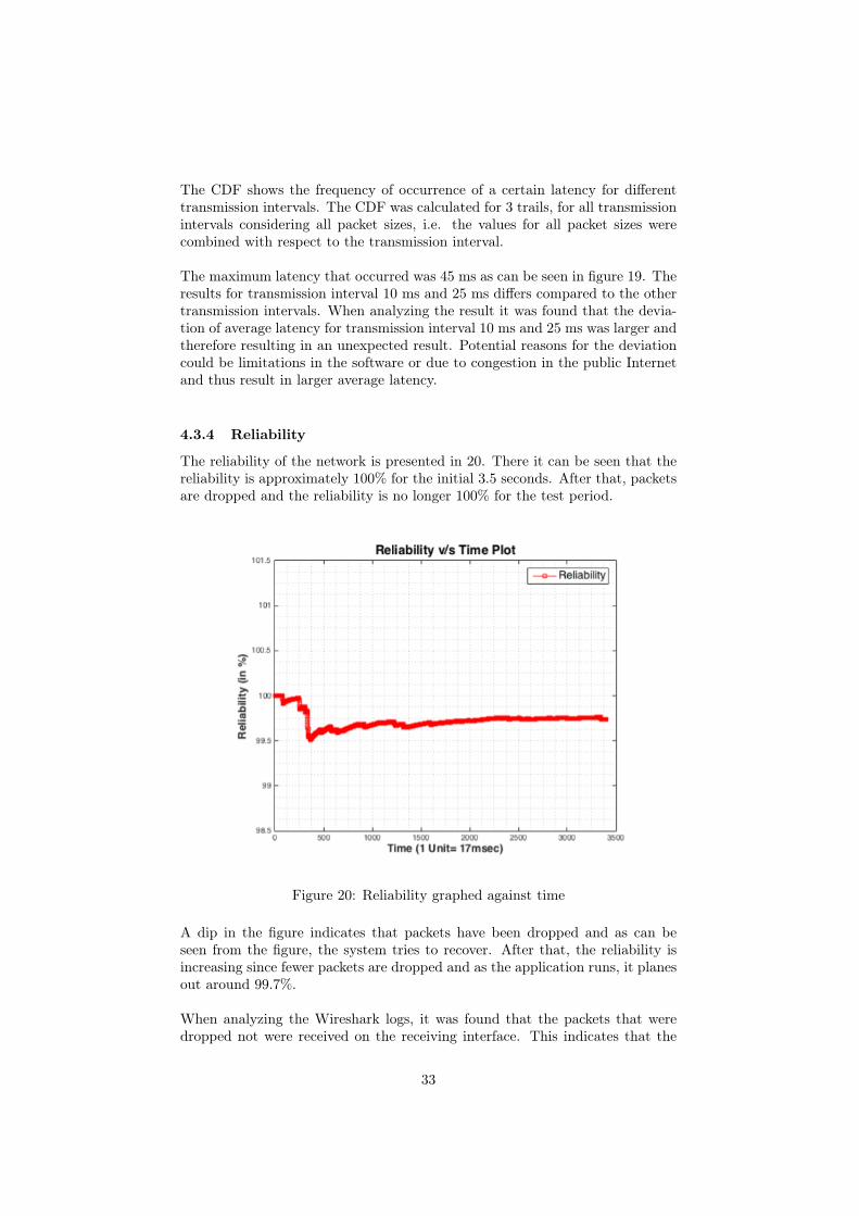
The reliability of the network is presented in 20. There it can be seen that thereliability is approximately 100% for the initial 3.5 seconds. After that, packetsare dropped and the reliability is no longer 100% for the test period.
Figure 20: Reliability graphed against time
A dip in the figure indicates that packets have been dropped and as can beseen from the figure, the system tries to recover. After that, the reliability isincreasing since fewer packets are dropped and as the application runs, it planesout around 99.7%.
When analyzing the Wireshark logs, it was found that the packets that weredropped not were received on the receiving interface. This indicates that the
33

packets were dropped when traversing through the network. Potential reasonswhy packets are dropped could be congestion in the public Internet, unavail-ability, or software limitations.
Since UDP is a connectionless protocol, it does not establish a connection be-tween the sender and receiver and hence packet delivery can not be guaranteed.The use of UDP could be a reason why packets are dropped in the network.
34

5 General Discussion and ConclusionThe main goal of this thesis was to evaluate the performance of a non-commercialLTE network and to examine the readiness of the available IEC 61850-90-5 stackto support phasor communication over a wireless network. The IED prototypeused for testing was based on an IEC 61850-90-5 open source implementation.To suit the purpose of the project, changes were made to the code and theapplication as a whole. Test cases were derived from metrics such as latency,availability, reliability, and throughput.
It can be concluded that long range wireless communication such as 4G LTEwill play a major role in machine to machine communication since it easily canbe deployed without incurring high costs compared to wired communication.Moreover do the wireless technology offer other advantages over the wired al-ternative such as mobility and remote location coverage. The IEC 61850-90-5protocol will be a key component for wireless communication within the smartgrid since it enables routing of the standardized GOOSE and SV messages in IPpacket format, which is needed when using the commercial 4G LTE network.
The overall performance of the non-commercial 4G LTE network when usingIEC 61850-90-5 stack is promising for smart grid applications considering highthroughput. Latency can be too high and reliability too low for the applicationswith the most stringent communication requirements, as discussed in 3.5. Theresult indicates that the IEC 61850-90-5 stack in combination with 4G LTEwould be suitable for the applications with less demanding communication re-quirements.
The throughput tests indicate high throughput for various packet sizes. Whenthe packet size exceeds 950 bytes there is a decrease in throughput, which be-comes more prominent for lower transmission intervals (when sending morepackets per second). As theorized in 4.3.2, potential reasons for this behav-ior could be packet segmentation or issues in the core network.
The average latency results that were measured can for time critical applica-tions be too high since some of the latency measurements were around 45 ms.This is remarkably high compared to ≤ 3ms, that was one of the most stringentcommunication requirements for some applications. As explained in 4.3.3, theresults were inconsistent and therefore a CDF was plotted. In the CDF it wasshown that the deviation of average latency for some transmission intervals waslarger than expected and thus resulting in larger average latency. As theorized,potential reasons could be software limitation or congestion in the public Inter-net.
The reliability results from the measurements showed a reliability around 99.7%,which would be too low for some applications that demand higher reliability.One potential reason for low reliability could be due to the use of public Inter-net when conducting the tests. Another potential reason could, as theorized in4.3.4, be the use of UDP. UDP does not ensure packet delivery and as a result,packets can be dropped while traversing the network.
35

The availability test of the network indicates more packet drops during certainperiods of the day. One potential reason why packet drops occurred more fre-quently during 9:00 AM and 1:00 PM could be that the network was not onlydedicated for the tests. This could be the result of "office hours", i.e more peo-ple are using the network during these hours. Hence could other traffic stressthe network and affect the results.
The tests were carried out in a non-commercial LTE network environment andthe performance may differ in a commercial LTE environment due to usage,different configurations, and QoS.
Reliability and availability are something that has to be ensured since failure oranomalies within power systems can cause major damages both to equipmentand humans. Further work is needed to analyze and optimize certain featuressuch as how latency can be reduced and reliability increased. This is importantif the protocol will be used for time critical applications within the smart grid.
The overall result of the project is satisfying but some problems occurred duringthe course of the project, which may have affected the final result. There weresome technical issues with the externally provided non-commercial 4G LTE in-frastructure, which took time to resolve and hence reduced the time for testingand evaluation of the results. Moreover, the time allocated for various steps ofthe initial phase of the project could have been better distributed since moretime for troubleshooting, testing and evaluating the result was needed.
5.1 Future WorkThe result of this thesis project is based on research, implementation, test, andanalyses of the IEC 61850-90-5 protocol. The main goal of this thesis was tobenchmark a non-commercial 4G LTE network and to investigate the applicabil-ity and readiness of the IEC 61850-90-5 stack to support phasor communicationover a wireless network.
Tests were conducted to evaluate the performance metrics of the non-commercial4G LTE network whens using the IEC 61850-90-5 stack, such as reliability, avail-ability, latency, and throughput. Time limitations affected the number of tests,therefore it would be sensible to perform more test in order to get more accurateresults.
Another aspect that needs to be considered is that the tests were only con-ducted during office hours, except the availability test that was run for 24 hoursconsecutively. The availability test indicates that the network availability waslower during certain periods of the day. Therefore more tests must be conductedduring other hours in order to conclude if there is a link between low availabilityand usage of the network elsewhere.
A more in-depth analysis of the results is needed since this merely is a bench-mark of the non-commercial 4G LTE network when using the IEC 61850-90-5protocol. Since the non-commercial 4G LTE network is provided by an external
36

source, an in-depth analysis of the network is out of the scope for this thesisproject. It would be interesting if the external source investigated the behaviorand characteristics of the network since it may give an explanation to some ofthe results. Interesting aspects to investigate would be the underlying causewhy latencies differed as much as it did, why the availability dropped duringcertain periods of the day, and why the reliability was low.
The core network that was provided for the project was located approximately100 km from where the tests were conducted. The core network will in theforeseeable future be moved closer to the base station. This could increase theperformance and reduce latencies since the distance that the data travels willbe shorter.
As mentioned previously in this paper, the tests were carried out in a non-commercial 4G LTE network. Therefore tests over the commercial 4G LTEnetwork is needed since the commercial network may differ in performance.
Another thing that needs to be addressed when working with sensitive data isthe security, which also has to be considered in the future. If the IEC 61850-90-5 is used with IP over the 4G LTE network, security threats are introduced.Therefore extensive security is needed that provides protection and countermea-sures for different types of security threats.
37

References[1] A. B. M. Shawkat Ali. Smart Grids - Opportunities, Developments, and
Trends, volume 132 of Green Energy and Technology. Springer London, 1edition, 2013. [E-book] Available: Springer Link, 7 August 2017.
[2] Mohamed A. Sherif Mahmoud Abdulla ElNashar, Ayman El-saidny. De-sign, Deployment and Performance of 4G-LTE Networks: A Practical Ap-proach. John Wiley & Sons, 1 edition, 2014. [E-book] Available: ProQuestEbook Central, 7 August 2017.
[3] Kato Nei Fadullah Md. Zubail. Evolution of Smart Grids. SpringerBriefs inElectrical and Computer Engineering. Springer International Publishing, 1edition, 2015. [E-book] Available: Springer Link, 7 August 2017.
[4] A. Dung Nguyen Geert J. Heijenk Boudewijn R. Havenkort Frans CampfensGeorgios Karagiannis, Giang T. Pha. Performance of lte for smart gridcommunication. In Measurement, Modelling, and Evaluation of ComputingSystems and Dependability and Fault Tolerance. Lecture Notes in ComputerScience, volume 8376, pages 225–239. Springer, 2014.
[5] IEC. Communication networks and systems for power utility automation– part 8-1: Specific communication service mapping (scsm) - mappings tomms (iso 9506-1 and iso 9506-2) and to iso/iec 8802-3. Technical report.
[6] IEC. Communication networks and systems for power utility automation– part 7-2: Basic information and communication structure – abstractcommunication service interface (acsi), ed2.0. Technical report, Interna-tional Electrotechnical Commission, CH-1211 Geneva 20 Switzerland, Au-gust 2010.
[7] IEC. Communication networks and systems for power utility automa-tion – part 7-1: Basic communication structure – principles and models,ed2.0. Technical report, International Electrotechnical Commission, CH-1211 Geneva 20 Switzerland, July 2011.
[8] IEC. Communication networks and systems for power utility automation –part 9-2: Specific communication service mapping (scsm) - sampled valuesover iso/iec 8802-3, ed2.0. Technical report, International ElectrotechnicalCommission, CH-1211 Geneva 20 Switzerland, September 2011.
[9] IEC. Communication networks and systems for power utility automation –part 90-5: Use of iec 61850 to transmit synchrophasor information accord-ing to ieee c37.118, ed1.0. Technical report, International ElectrotechnicalCommission, CH-1211 Geneva 20 Switzerland, May 2012.
[10] IEC. Communication networks and systems for power utility automa-tion – part 1: Introduction and overview, ed2.0. Technical report, In-ternational Electrotechnical Commission, CH-1211 Geneva 20 Switzerland,March 2013.
[11] IEC. Communication networks and systems for power utility automation– part 5: Communication requirements for functions and device models,
38

ed2.0. Technical report, International Electrotechnical Commission, CH-1211 Geneva 20 Switzerland, January 2013.
[12] Herb Falk IEC 61850 Users Group. Iec tr 61850-90-5 open sourceproject. http://iec61850.ucaiug.org/90-5/default.aspx, 2010 (ac-cessed November, 2016).
[13] IEEE. Ieee standard for synchrophasor measurements for power systems.Technical report, Institute of Electrical and Electronics Engineers, 3 ParkAvenue, New York, NY, 10016-5997, December 2011.
[14] IEEE. Ieee standard for synchrophasor measurements for power systems.Technical report, Institute of Electrical and Electronics Engineers, 3 ParkAvenue, New York, NY, 10016-5997, December 2011.
[15] Asim Aftab Ikbal Ali, S. M. Suhail Haussain. Communication modeling ofphasor measurement unit based on iec 61850-90-5. In 2015 Annual IEEEIndia Conference (INDICON), pages 1–6. IEEE, 2015.
[16] S.M. Suhail Hussain Ikbal Ali, Mohd Asim Aftab. Performance comparisonof iec 61850-90-5 and ieee c37.118.2 based wide area pmu communicationnetworks. In Journal of Modern Power Systems and Clean Energy, vol-ume 4, pages 487–495. Springer Berlin Heidelberg, 2016.
[17] Marina Thottan Kenneth c. Budka, Jayant G. Deshpande. Communica-tion Networks for Smart Grids - Making Smart Grids Real. ComputerCommunications and Networks. Springer London, 2014. [E-book] Avail-able: Springer Link, 7 August 2017.
[18] Lee Wilaiporn Kheaksong Adisorn, Prayote Akara. Performance evaluationof smart grid communications via network simulation version 3. In 13thInternational Conference on Electrical Engineering/Electronics, Computer,Telecommunications and Information Technology (ECTI-CON), pages 1–5.IEEE, 2016.
[19] R.E. Mackiewicz. Overview of iec 61850 and benefits. In 2006 IEEE PowerSystems Conference and Exposition, pages 623–630. IEEE, 2006.
[20] Uthman Baroudi Bilal Saeed Muhammad Musaddiq, Shehryar Kahn. Per-formance evaluation of iec 61850 under wireless communication networks.In MEDES ’14 Proceedings of the 6th International Conference on Man-agement of Emergent Digital EcoSystems, pages 90–94. ACM, 2014.
[21] Saifu Rahman Murat Kuzlu, Manisa Pipattanasomporn. Communicationnetwork requirements for major smart grid applications in han, nan andwan. In Computer Networks, volume 67, pages 74–88. Elsevier B.V, July2014.
[22] Tarlochan S. Siduh Palak P. Parikh, Mitalkumar G. Kanabar. Opportuni-ties and challenges of wireless communication technologies for smart gridapplications. In Power and Energy Society General Meeting, 2010 IEEE,pages 1–7. IEEE, 2010.
39

[23] Hans Stutvoet. Intelligent electronic device. https://www.svri.nl/en/intelligent-electronic-device-ied/, 2014 (accessed August, 2017).
[24] Taskin Kocak Vehbi C. Gungor, Dilan Sahin. Smart grid technologies:Communication technologies and standards. In IEEE Transactions on In-dustrial Informatics, volume 7, pages 529–539. IEEE, 2011.
40