performance and energy savings of variable refrigerant...
TRANSCRIPT

PERFORMANCE AND ENERGY SAVINGS OF VARIABLE
REFRIGERANT TECHNOLOGY IN COLD WEATHER CLIMATES
Conservation Applied Research & Development (CARD) FINAL REPORT
Prepared for: Minnesota Department of Commerce, Division of Energy Resources
Prepared by: Energy Management Solutions, Inc.
OES-04042011-37612 | February 2015

Prepared by: Gary A. Swanson, PE Cole A. Carlson Energy Management Solutions, Inc. 684 Excelsior Blvd., Suite 200 Excelsior, MN 55331 952-767-7450 EMS webpage: www.emsenergy.com
Project Partners: First National Plaza Grand View Lodge Minnesota Power Cloquet Service Center St. Otto’s Care Center The Muni: Wayzata Wine and Spirits/Bar and Grill
Contract Number: 37612
Prepared for Minnesota Department of Commerce, Division of Energy Resources Mike Rothman, Commissioner, Department of Commerce Bill Grant, Deputy Commissioner, Department of Commerce, Division of Energy Resources Joe Plummer, Project Manager Phone: 651-539-1874 Email: [email protected]
ACKNOWLEDGEMENTS This project was supported in part (or in whole) by a grant from the Minnesota Department of Commerce, Division of Energy Resources, through the Conservation Applied Research and Development (CARD) program, which is funded by Minnesota ratepayers.
The authors would also like to acknowledge the following individuals and organizations for their contributions to the project: Brian Bernander St. Otto’s Care Center Matt Blocker Mitsubishi Electric Heating and Cooling Josh Cameron Grand View Lodge Tim Gallagher Minnesota Power Don Johaneson City of Wayzata Craig Kedrowski Minnesota Power Scott Lewchuk Daikin McQuay Joe Plummer State of Minnesota John Sawyer UMD Facilities Management Bill Snyder Gustave A. Larson Company Brenda Vaverek Unity Family Healthcare Zachary Wehr UF Inc.
DISCLAIMER This report does not necessarily represent the view(s), opinion(s), or position(s) of the Minnesota Department of Commerce (Commerce), its employees or the State of Minnesota (State). When applicable, the State will evaluate the results of this research for inclusion in Conservation Improvement Program (CIP) portfolios and communicate its recommendations in separate document(s).
Commerce, the State, its employees, contractors, subcontractors, project participants, the organizations listed herein, or any person on behalf of any of the organizations mentioned herein make no warranty, express or implied, with respect to the use of any information, apparatus, method, or process disclosed in this document. Furthermore, the aforementioned parties assume no liability for the information in this report with respect to the use of, or damages resulting from the use of, any information, apparatus, method, or process disclosed in this document; nor does any party represent that the use of this information will not infringe upon privately owned rights.

EXECUTIVE SUMMARY
This report examines the attributes of variable refrigerant flow (VRF) systems and their applicability for service in cold weather climates similar to that of Minnesota. This was accomplished by identifying five separate facilities with currently installed VRF systems, collecting and analyzing sets of energy consumption data from each host site, developing a method for estimating energy savings compared to baseline conditions, and providing a comprehensive discussion of VRF technology. The following host sites were selected for participation in this study in order to provide a useful cross-sectional representation of systems and building types:
1) First National Plaza – Cloquet, MN
2) Grand View Lodge – Nisswa, MN
3) Minnesota Power Service Center – Cloquet, MN
4) St. Otto’s Care Center – Little Falls, MN
5) The Muni: Wine and Spirits/Bar and Grill – Wayzata, MN
Building energy consumption pre- and post-VRF installation for each of the aforementioned host sites was collected and analyzed to quantify the energy savings realized by switching from conventional heating, ventilation, and air conditioning (HVAC) systems to VRF systems. By converting each facility’s total energy consumption into equivalent British thermal units (Btu) and then weather-normalizing it, a baseline level of energy consumption was determined prior to installation of the VRF system. This baseline was then compared to the weather-normalized energy usage of the VRF system after installation, accounting for any additional significant changes.
Using this methodology, the results of the study yielded average energy savings of 517 therms/ton/year of heating capacity and 3,705 kWh/ton/year of cooling capacity. The percentage of annual building energy use saved ranged from 10% to 82%. The most sensitive factors affecting these results were type of building, age of building, type of VRF system installed, and type of HVAC system replaced. Due to the myriad of factors affecting energy consumption, however, actual energy savings may vary considerably from the range of values obtained here.
An economic analysis of this technology yielded average incremental installed costs of roughly 14% over more traditional HVAC technology and simple payback periods (SPPs) of 5.1 to 19.1 years without a rebate and 4.8 to 17.3 years with a rebate. Rebates corresponding to energy savings for cooling were assumed to be paid by electric utilities; while rebates corresponding to energy savings for heating were assumed to be paid by the utility (electric or natural gas) that was providing heating prior to installation of the VRF system. These assumptions were made to help clarify and simplify the calculations used to determine the baseline HVAC systems with which the VRF systems were compared against.
VRF in Cold Weather Climates i Energy Management Solutions, Inc. OES-04042011-37612 | February 2015
TABLE OF CONTENTS
Executive Summary ........................................................................................................................................ i
Figures . . . . . . . . . . . . . . . . . . . . . . . . . . . . . . . . . . . . . . . . . . . . . . . . . . . . . . . . . . . . . . . . . . . . . . . . . . . . . . . . . . . . . . . . . . . . . . . . . . . . . . . . . . . . . . . . . . . . . . . . . . . . . . . iv
Tables . . . . . . . . . . . . . . . . . . . . . . . . . . . . . . . . . . . . . . . . . . . . . . . . . . . . . . . . . . . . . . . . . . . . . . . . . . . . . . . . . . . . . . . . . . . . . . . . . . . . . . . . . . . . . . . . . . . . . . . . . . . . . . . . . . v
Definitions . . . . . . . . . . . . . . . . . . . . . . . . . . . . . . . . . . . . . . . . . . . . . . . . . . . . . . . . . . . . . . . . . . . . . . . . . . . . . . . . . . . . . . . . . . . . . . . . . . . . . . . . . . . . . . . . . . . . . . . . . vi
Acronyms and Abbreviations . . . . . . . . . . . . . . . . . . . . . . . . . . . . . . . . . . . . . . . . . . . . . . . . . . . . . . . . . . . . . . . . . . . . . . . . . . . . . . . . . . . . . . . vi i i
Introduction . . . . . . . . . . . . . . . . . . . . . . . . . . . . . . . . . . . . . . . . . . . . . . . . . . . . . . . . . . . . . . . . . . . . . . . . . . . . . . . . . . . . . . . . . . . . . . . . . . . . . . . . . . . . . . . . . . . . . . . 1
Variable Refrigerant Flow (VRF) Systems . . . . . . . . . . . . . . . . . . . . . . . . . . . . . . . . . . . . . . . . . . . . . . . . . . . . . . . . . . . . . . . . . . . . . . 2
Overview of Technology ........................................................................................................................... 2
Major Manufacturers ................................................................................................................................ 4
Applications: VRF Systems vs. Traditional HVAC Systems ........................................................................ 4
Types of VRF Systems................................................................................................................................ 5
Refrigerant Modulation ............................................................................................................................ 7
Electronic Expansion Valve ....................................................................................................................... 8
Design Considerations . . . . . . . . . . . . . . . . . . . . . . . . . . . . . . . . . . . . . . . . . . . . . . . . . . . . . . . . . . . . . . . . . . . . . . . . . . . . . . . . . . . . . . . . . . . . . . . . . . . . . . 9
Step 1: Perform a Load Profile Analysis .................................................................................................... 9
Step 2: Determine Potential for Simultaneous Heating and Cooling (VRF-HR) ........................................ 9
Step 3: Size Outdoor and Indoor Units ................................................................................................... 10
Step 4: Develop Fresh Air Ventilation Strategy ....................................................................................... 10
Step 5: Select Indoor Units...................................................................................................................... 11
Step 6: Design Refrigerant Piping Network ............................................................................................ 12
Step 7: Verify Compliance with ASHRAE Standard 15-2010 and Standard 34-2010 .............................. 12
Step 8: Examine Life-Cycle Costs............................................................................................................. 13
Step 9: Select a Control System .............................................................................................................. 15
Step 10: Examine Future Building Expansion or Reconfiguration Plans ................................................. 16
PERFORMANCE Analysis Case Studies . . . . . . . . . . . . . . . . . . . . . . . . . . . . . . . . . . . . . . . . . . . . . . . . . . . . . . . . . . . . . . . . . . . . . . . . . . 17
Methodology ........................................................................................................................................... 17
First National Plaza ................................................................................................................................. 18
Grand View Lodge – Main Lodge ............................................................................................................ 20
Minnesota Power Cloquet Service Center .............................................................................................. 24
St. Otto’s Care Center ............................................................................................................................. 27
VRF in Cold Weather Climates ii Energy Management Solutions, Inc. OES-04042011-37612 | February 2015

The Muni: Wayzata Wine and Spirits/Bar and Grill ................................................................................ 30
Inclusion in Utility DSM Programs . . . . . . . . . . . . . . . . . . . . . . . . . . . . . . . . . . . . . . . . . . . . . . . . . . . . . . . . . . . . . . . . . . . . . . . . . . . . . . . . 35
Conclusions . . . . . . . . . . . . . . . . . . . . . . . . . . . . . . . . . . . . . . . . . . . . . . . . . . . . . . . . . . . . . . . . . . . . . . . . . . . . . . . . . . . . . . . . . . . . . . . . . . . . . . . . . . . . . . . . . . . . . . 38
References . . . . . . . . . . . . . . . . . . . . . . . . . . . . . . . . . . . . . . . . . . . . . . . . . . . . . . . . . . . . . . . . . . . . . . . . . . . . . . . . . . . . . . . . . . . . . . . . . . . . . . . . . . . . . . . . . . . . . . . . 41
Appendix A: Additional Resources . . . . . . . . . . . . . . . . . . . . . . . . . . . . . . . . . . . . . . . . . . . . . . . . . . . . . . . . . . . . . . . . . . . . . . . . . . . . . . . . 42
Appendix B: Supplementary information for first NAtional Plaza . . . . . . . . . . . . . . . . . . . . . . . . . . . . 43
Appendix C: Supplementary information for Grand View Lodge . . . . . . . . . . . . . . . . . . . . . . . . . . . . . . . 47
Appendix D: Supplementary information for Minnesota Power Cloquet Service Center . . . . . . . . . . . . . . . . . . . . . . . . . . . . . . . . . . . . . . . . . . . . . . . . . . . . . . . . . . . . . . . . . . . . . . . . . . . . . . . . . . . . . . . . . . . . . . . . . . . . . . . . . . . . . . . . . . . . . . . . . . . . . . . . 51
Appendix E: Supplementary information for St. Otto’s Care Center . . . . . . . . . . . . . . . . . . . . . . . . . 55
Appendix F: Supplementary information for The Muni: Wayzata Wine and Spirits . . . . . . . . . . . . . . . . . . . . . . . . . . . . . . . . . . . . . . . . . . . . . . . . . . . . . . . . . . . . . . . . . . . . . . . . . . . . . . . . . . . . . . . . . . . . . . . . . . . . . . . . . . . . . . . . . . . . . . . . . . . . . . . . . . . . . . . . . . . 59
VRF in Cold Weather Climates iii Energy Management Solutions, Inc. OES-04042011-37612 | February 2015

FIGURES
Figure 1: Typical cassette-style ceiling indoor unit ...................................................................................... 2
Figure 2: Two outdoor condensing units installed on a rooftop ................................................................... 2
Figure 3: Generalized configuration of a typical VRF system ..................................................................... 3
Figure 4: Piping configuration of heat pump VRF systems .......................................................................... 5
Figure 5: Piping configuration of two-pipe heat recovery VRF systems ...................................................... 6
Figure 6: Parallel piping configuration of three-pipe heat recovery VRF systems ....................................... 7
Figure 7: Hybrid series/parallel piping configuration of three-pipe heat recovery VRF systems ................ 7
Figure 8: A cutaway view of an EEV with motor and drive assembly ......................................................... 8
Figure 9: Various designs and applications of VRF indoor units ............................................................... 12
Figure 10: Mitsubishi Electric local controller ........................................................................................... 15
Figure 11: Example of a central system controller ..................................................................................... 16
Figure 12: One of the two outdoor condensing units at First National Plaza in Cloquet, Minnesota. ........ 18
Figure 13: Monthly energy consumption of First National Plaza from 2006-2011 .................................... 19
Figure 14: The two outdoor condensing units at the Main Lodge of Grand View Lodge. ......................... 22
Figure 15:One of the diffusers for the ceiling-concealed ducted indoor units, and its local controller ...... 22
Figure 16: Monthly energy consumption per ft2 of Grand View Lodge from 2009-2013 .......................... 23
Figure 17: Monthly energy consumption of the Minnesota Power Cloquet Service Center 2004-2012 .... 25
Figure 18: Two of the six outdoor condensing units at St. Otto’s Care Center in Little Falls, MN. .......... 28
Figure 19: Monthly energy consumption of St. Otto’s Care Center from 2008-2012 ................................ 29
Figure 20: One of the two outdoor condensing units at The Muni in Wayzata, Minnesota. ...................... 31
Figure 21: One of the cassette-style indoor units and its local controller ................................................... 32
Figure 22: Monthly energy consumption per ft2 of The Muni from 2009-2012 ......................................... 32
VRF in Cold Weather Climates iv Energy Management Solutions, Inc. OES-04042011-37612 | February 2015

TABLES
Table 1: Applicable Baseline Technologies for VRF Systems ..................................................................... 4
Table 2: Literature Review of VRF Savings Estimates .............................................................................. 14
Table 3: Facilities with Analyzed VRF Systems ........................................................................................ 17
Table 4: 2006-2011 Total Annual Weather-Normalized Energy Consumption of First National Plaza .... 19
Table 5: Summary of Energy and Cost Savings from the VRF Installation at First National Plaza .......... 20
Table 6: 2009-2013 Total Annual Normalized Energy Consumption of Grand View Lodge .................... 23
Table 7: Summary of Energy and Cost Savings from the VRF Installation at Grand View Lodge ........... 23
Table 8: 2004-2012 Total Annual Weather-Normalized Energy Consumption of the Minnesota Power Cloquet Service Center ............................................................................................................................... 26
Table 9: Summary of Energy and Cost Savings from the VRV Installation at the Minnesota Power Cloquet Service Center ............................................................................................................................... 26
Table 10: 2008-2012 Total Annual Weather-Normalized Energy Consumption of St. Otto’s Care Center .................................................................................................................................................................... 29
Table 11: Summary of Energy and Cost Savings from the VRF Installation at St. Otto’s Care Center ..... 29
Table 12: 2009-2012 Total Annual Normalized Energy Consumption of The Muni ................................. 33
Table 13: Summary of Energy and Cost Savings from the VRF Installation at The Muni ........................ 33
VRF in Cold Weather Climates v Energy Management Solutions, Inc. OES-04042011-37612 | February 2015

DEFINITIONS 1
BACnet: A standardized communications protocol for building automation and control networks. BC Controller: Mitsubishi’s branch circuit (BC) controller, which both modulates refrigerant flow and serves as the connection point between a single outdoor unit and multiple indoor units. Coefficient of Performance (COP): Ratio of work performed by a device to the energy it consumes. Comfort Zone: Area on psychometric chart that shows conditions of temperature, humidity, and sometimes air movement in which most people are comfortable. Condensing unit: The portion of a refrigeration system where the compression and condensation of refrigerant is accomplished. Constant Air Volume (CAV): An HVAC system that has a variable supply-air temperature but constant air-flow rates. Geothermal Heat Pump: An underground or underwater temperature source used for the operation of a heating or cooling system. Degree Day: A unit used to relate any given day's temperature to the energy demands of a conditioned space. The reference temperature is typically 65°F. Heating degree days reflect the amount of heating required; while cooling degree days indicate the amount of cooling required. Derating Factor: A factor used to express the reduction in heating capacity of a VRF system when operating in lower temperature conditions from that for which the original heating capacity was established. Diversity Factor: A measure of the probability that a particular piece of equipment will come on coincidentally to another piece of equipment within the same system. Economizer: A control strategy that utilizes excess outdoor air to provide cooling for the building during favorable outdoor conditions. This reduces energy used by the HVAC system for cooling. Electronic Expansion Valve: A valve that precisely controls the level of superheat in a VRF system. It consists of a synchronous electric motor that divides its full rotation into a large number of small, incremental steps. Energy Efficiency Ratio (EER): A rating for room air conditioners that lists how many Btu’s of cooling output it provides for each watt-hour of energy it uses. Energy Use Index (EUI): A figure of merit used in an energy analysis with units of Btu per ft2 per year. Enthalpy: A measure of the total energy content of an enclosed system. Evaporator: A device in which a liquid refrigerant is vaporized. Some superheating usually takes place. Four-Way Valve: A device in a heat pump that is electrically controlled to reverse the flow of refrigerant as the system is switched from cooling to heating. Heat Exchanger: A device for the transfer of heat energy from the source to the conveying medium. Heat Pump: A compression cycle system used to supply heat to a temperature-controlled space. The same system can also remove heat from the same space. Higher Heating Value (HHV): The amount of heat released by a specified quantity (initially at 25°C) once combusted and the products have returned to 25°C. This takes into account the latent heat of vaporization of water in the combustion products.
1 Majority of definitions provided by McQuay International. Available at: <http://www.mcquay.com/eprsup/mcquaycom/parts/terms.pdf>
VRF in Cold Weather Climates vi Energy Management Solutions, Inc. OES-04042011-37612 | February 2015
Latent Heat: Heat that produces a change of state without a change in temperature; i.e., ice to water at 32°F or water to steam at 212°F. LonWorks: A networking platform created by Echelon Corporation for networking an assortment of devices used for automating various systems within buildings. Lower Heating Value (LHV): The amount of heat released by combusting a specified quantity initially at 25°C and returning the combustion products to 150°C. This assumes the latent heat of vaporization of water in the reaction products is not recovered. Nationally Recognized Testing Laboratories (NRTLs): A set of recognized independent organizations that provide rigorous product safety testing and certification services to manufacturers. When products pass these tests they can be labeled (and advertised) as NRTL Certified. Pressure Drop: Decrease in pressure due to friction of a fluid or vapor as it passes through a tube or duct. Psychometric Chart: Chart that shows relationship between the temperature, pressure, and moisture content of the air. R-410A: A refrigerant used for space conditioning systems that does not contribute to ozone depletion. Refrigerant: Substance used in space conditioning. It absorbs heat in evaporator by change of state from a liquid to a gas, and releases its heat in a condenser as the substance returns from the gaseous state back to a liquid state. Relative Humidity: The percentage of water vapor present in a given quantity of air compared to the amount it can hold at its temperature. Seasonal Energy Efficiency Ratio (SEER): A rating for central air conditioning units that lists the total Btu cooling output provided during one year of operation divided by its total watt-hour energy input. Sensible Heat: Heat that can be measured or felt. Sensible heat always causes a temperature rise. Suction Line: Tube or pipe used to carry refrigerant gas from evaporator to compressor. Superheat: Heat added to a vapor after all liquid has been vaporized. Therm: Equivalent unit for expressing 100,000 Btu. Thermal Zone (Zone): An individual space or group of neighboring indoor spaces that have similar thermal loads. Building codes may require zoning to save energy in commercial buildings. Thermistor: Essentially a semiconductor with electrical resistance that varies inversely with temperature. Ton of Refrigeration: Refrigerating effect equal to the melting of one (1) ton of ice in 24 hours. This may be expressed as follows: 288,000 Btu/24 hr., 12,000 Btu/1hr., 200 Btu/min. Variable Air Volume (VAV): An HVAC system that has a stable supply-air temperature, and varies the air flow rate to meet the temperature requirements.
VRF in Cold Weather Climates vii Energy Management Solutions, Inc. OES-04042011-37612 | February 2015
ACRONYMS AND ABBREVIATIONS
A: ampere(s) ACH: air changes per hour AHRI: Air Conditioning, Heating, and Refrigeration Institute ANSI: American National Standards Institute ASHRAE: American Society of Heating, Refrigerating, and Air-Conditioning Engineers BMS: building management system(s) Btu: British thermal unit CAV: constant air volume CDD: cooling degree day(s) COP: coefficient of performance DOAS: dedicated outdoor air system DOE: U.S. Department of Energy DSM: demand side management DX: direct-expansion EER: energy efficiency ratio EEV: electronic expansion valve ERV: energy recovery ventilator EUI: Energy Use Index HDD: heating degree day(s) HEPA: high-efficiency particulate air HHV: higher heating value HRV: heat recovery ventilator HVAC: heating, ventilation, and air conditioning IAQ: indoor air quality ICC: International Code Council kWh: kilowatt hour(s) LEED: Leadership in Energy and Environmental Design LHV: lower heating value MWh: megawatt hour(s) NRTLs: Nationally Recognized Testing Laboratories RCL: refrigerant concentration limits SEER: seasonal energy efficiency ratio USGBC: U.S. Green Building Council V: volt(s) VAV: variable air volume VFD: variable frequency drive VRF: variable refrigerant flow VRF-HR: variable refrigerant flow with heat recovery VRV: variable refrigerant volume W: watts(s)
VRF in Cold Weather Climates viii Energy Management Solutions, Inc. OES-04042011-37612 | February 2015
INTRODUCTION
Overall Scope and Goals of Project
There is currently a wide range of heating, ventilation, and air conditioning (HVAC) systems available for use in residential and commercial buildings. Most of these systems have been well known and widely implemented in the United States (U.S.) for many decades. Variable refrigerant flow (VRF) systems, however, were introduced to the U.S. market in 2002 as an energy-efficient alternative and remain a relatively unknown option for providing heating and cooling in the built environment. While new to the U.S., VRF systems have enjoyed widespread acceptance in Japan and Europe for more than 20 years and currently account for 33% to 50% of the market share in those locations. The primary goal of this project is to address the performance and applicability uncertainties of VRF systems placed in service in cold weather climates. Since utilities have historically had a difficult time calculating energy savings and providing the associated incentives for VRF systems through their demand side management (DSM) programs, a standardized method for estimating savings was developed and applied to energy consumption measurements to verify and quantify energy savings compared to baseline levels.
Space conditioning in Minnesota is estimated to account for roughly 38% of building energy use—or 15% of the state’s total energy consumption. This equates to approximately 82 billion kWh for 2010 Minnesota energy data.2 With only minimal market penetration currently, widespread utilization of VRF technology has the potential to cumulatively save the state billions of kWh per year, plus hundreds of millions of dollars each year in energy and maintenance costs. The findings and recommendations from this report are designed to be highly applicable and representative for Minnesota, and, in terms of energy costs and maintenance, are an issue for every building owner. It is anticipated that this report will serve as a high-level evaluation tool for building engineers, owners, utility DSM program managers, and other key decision makers for determining if VRF technology is an appropriate option for the application at hand.
2 U.S. Energy Information Administration. "Minnesota Data." Independent Statistics and Analysis: U.S. Energy Information Administration. U.S. Department of Energy, Sep 2012. Web. 9 Oct 2012.
VRF in Cold Weather Climates 1 | P a g e Energy Management Solutions, Inc. OES-04042011-37612 | August 2014

VARIABLE REFRIGERANT FLOW (VRF) SYSTEMS
Overview of Technology
Figure 1: Typical cassette-style ceiling indoor unit
The variable refrigerant flow (VRF) concept was first developed and designed in 1982 by Daikin Industries in Japan, which named and protected the term “variable refrigerant volume” (VRV). This forced the rest of the industry to develop a generic name for this technology—VRF. VRF is an HVAC system configuration in which heat is transmitted through refrigerant lines between an outdoor condensing unit and a network of indoor evaporators. The term “variable refrigerant flow” is used to describe the system’s ability to continuously modulate the rate at which refrigerant is distributed within the system. Most VRF systems use variable frequency drives (VFDs) and electronic expansion valves (EEVs) to accomplish this flow control. This translates to the utilization of many indoor units of differing capacities and configurations, individualized comfort control, simultaneous heating and cooling in different zones, and the unique possibility for heat recovery from one zone to another.
Figure 2: Two outdoor condensing units installed on a rooftop
These systems operate on the direct-expansion (DX) principle, where heat is transferred to or from the conditioned space directly by circulating refrigerant through the indoor units located near or within the conditioned area. In contrast, conventional HVAC systems transfer heat from the space to the refrigerant by circulating air or water throughout the building. VRF systems should not be confused with centralized variable air volume (VAV) systems which work by varying the air flow to the conditioned space based upon variation in thermal loads. Refrigerant flow control lies at the heart of many of the VRF system’s advantages as well as serving as the system’s major technical challenge. According to the American
VRF in Cold Weather Climates 2 | P a g e Energy Management Solutions, Inc. OES-04042011-37612 | August 2014

Society of Heating, Refrigerating, and Air-Conditioning Engineers (ASHRAE), typical capacities range from 5,000-120,000 Btu/hr for indoor units and 18,000-760,000 Btu/hr for outdoor units.3
VRF systems are enhanced versions of the more widely known ductless multi-split systems, which connect one outdoor condenser to several indoor evaporators. In multi-split systems, each indoor unit has its own separate set of refrigerant pipe work connecting it to the outdoor unit. The entire multi-split system is completely turned ON/OFF in response to a single master controller. VRF systems, however, continually adjust the flow of refrigerant through the use of an EEV whose opening is determined by the microprocessor receiving information from thermistor sensors in each indoor unit. This control is also linked to the outdoor unit, which responds by varying its compressor speed to match the total cooling and/or heating requirements. In turn, this allows multiple indoor units to be connected using a common refrigerant line, rather than requiring separate lines between each indoor unit and the outdoor unit.
Although there are many different approaches to designing and installing VRF systems, a generalized configuration of a VRF system is provided in Figure 3 for introductory conceptual purposes:
Figure 3: Generalized configuration of a typical VRF system4
3 "Chapter 18: Variable Refrigerant Flow." 2012 ASHRAE Handbook - HVAC Systems and Equipment. Inch-Pound Edition. Atlanta: ASHRAE, 2012. Print. 4 Bhatia, A. "HVAC Variable Refrigerant Flow Systems." Course No: M03-014. Continuing Education and Development, Inc. 24 Sep 2012. Reading.
Evaporator
Condenser
VRF in Cold Weather Climates 3 | P a g e Energy Management Solutions, Inc. OES-04042011-37612 | August 2014

Major Manufacturers
While the number of manufacturers of VRF systems seems to increase every year, it is important to consider the value of well-established manufacturing firms in providing research and development for new technologies, good quality control, and appropriate warranties. Some of the manufacturers with reputable experience as producers of VRV/VRF technologies include:
• Daikin AC (Americas), Inc. (www.daikin.com) • Fujitsu General America, Inc. (www.fujitsu-general.com) • LG Electronics U.S.A. Inc. (www.lg-vrf.com) • Mitsubishi Electric U.S., Inc. (www.mehvac.com) • Panasonic U.S.A. (shop.panasonic.com/hvac/) • Toshiba Carrier Corporation (www.toshiba-aircon.jp/)
(Note: This is not a complete list but a sample of manufacturers discovered while researching this report through industry literature, academic articles, and discussions with HVAC professionals.)
Applications: VRF Systems vs. Traditional HVAC Systems
The objective of all HVAC systems is to maintain desired environmental conditions in a space, providing thermal comfort for the occupants. This is crucial for maintaining conducive, productive work environments and healthy living spaces. Good thermal comfort in buildings results from providing the space with appropriate temperature, relative humidity, air motion, and pressure settings.
VRF systems are generally best suited to buildings with diverse, multiple zones requiring individual control, such as office buildings, hospitals, hotels, schools, and multi-tenant retail building (shopping malls). A VRF system does not compete well with rooftop systems in large low-rise buildings such as big-box retail stores.5 The emerging VRF market in the U.S. directly overlaps and competes with traditional HVAC systems in many different applications. Table 1 identifies some applicable baseline technologies by commercial building type.
Table 1: Applicable Baseline Technologies for VRF Systems6
Building Type Office School Retail Lodging Health Care Baseline HVAC
System VRF VRF-
HR VRF VRF-HR VRF VRF-
HR VRF VRF-HR VRF VRF-
HR
Packaged Single Zone AC with Gas Furnace
X X X X X X
Packaged Single Zone Heat Pump
X X X X X X
VAV with Electric Re-Heat
X X
VAV with Hot Water Re-Heat
X X
Four-Pipe Unit X X
5 Goetzler, William. "Variable Refrigerant Flow Systems." ASHRAE Journal. (April 2007): 24-31. Print. 6 Vowles, M.: (2010). Variable Flow Heat Pump EE Measures. Commercial New Construction Strategy Group
VRF in Cold Weather Climates 4 | P a g e Energy Management Solutions, Inc. OES-04042011-37612 | August 2014

Building Type Office School Retail Lodging Health Care Ventilator
Packaged Terminal AC Unit
X X X X X X
Ground-Source Heat Pump
X X X X X X
Split AC Systems X X X X
Multi-Split Systems X X X X X X X X X X
Types of VRF Systems
Heat Pump
Heat pump VRF systems are capable of reversing the direction of refrigerant flow to provide exclusive heating or cooling to the indoor space. This is accomplished through the use of a special four-way reversing valve. When the indoor units are in cooling mode, they act as evaporators where liquid refrigerant enters the coil and undergoes an evaporative phase change that extracts heat from the space. When the indoor units are in heating mode, they act as condensers where hot gas refrigerant enters the coil and undergoes a condensing phase change that releases heat into the space. All indoor units connected to a heat pump VRF system can use individual control and set points, but they all operate in the same mode of either heating or cooling at any given time. Due to the added heat of compression from the outdoor units, the efficiency of a heat pump VRF system in heating mode is higher than in cooling mode. Please see Figure 4 below for a layout of this type of system.
Figure 4: Piping configuration of heat pump VRF systems. Source: 2012 ASHRAE Handbook
Heat Pump with Heat Recovery
Variable refrigerant flow systems with heat recovery (VRF-HR) can provide simultaneous heating and cooling. To match a building’s load profiles, energy is transferred from one thermal zone to another through the refrigerant line. Thus only one energy source is necessary to provide both heating and cooling simultaneously. This allows all the indoor units of a single system to individually and independently operate in heating or cooling mode at any given time. Typically, extra heat exchangers are provided in distribution boxes that are used to transfer heat from the superheated refrigerant exiting the zone being cooled to the refrigerant that is going to the zone being heated. VRF-HR systems are equipped with other
Condenser
VRF in Cold Weather Climates 5 | P a g e Energy Management Solutions, Inc. OES-04042011-37612 | August 2014

enhanced features that allow the system to operate in a highly efficient, part-load, overall net-heating or net-cooling mode as demanded by the conditioned spaces. Please refer to Figures 5-7 for layouts of this type of system.
VRF-HR systems work best during shoulder seasons, usually periods during spring and fall when both heating and cooling may be required. Many traditional unitary HVAC systems have a challenging time efficiently maintaining comfortable conditions during these periods since they often must simultaneously operate separate heating and cooling systems for extended periods. With VRF-HR, buildings can be zoned so that these transitional periods are seamless and comfort is maintained. For instances when cooling loads are frequently greater than heating loads, VRF-HR systems can be designed to deliver the heat removed from space cooling into water for domestic hot water or leisure applications. This allows the heat recovery capability to be utilized for a greater portion of the year. Other applications for VRF-HR include: medium-sized to large buildings with a substantial core and internal gains, between zones on the north/south or east/west sides of a building, or when occupancy profiles are based on time of day.
The overall design approaches for VRF-HR are broken down into two categories: two-pipe and three-pipe systems. Two-pipe systems (see Figure 5) include a heat recovery control unit that acts as an intermediate heat exchanger between the indoor and outdoor unit(s). This control unit houses a series of gas/liquid separators and diverting valves to move high or low pressure refrigerant between the indoor units. Three-pipe systems (see Figure 6 and Figure 7) have a low-pressure vapor pipe, a high-pressure vapor pipe, and a liquid pipe between the outdoor unit and the heat recovery unit(s). Each indoor unit connects to the heat recovery control unit through a port, which has separate liquid and vapor pipes. These ports can be controlled in various manners, depending upon the manufacturer. There does not appear to be a clear-cut advantage for one design approach over the other since both can provide simultaneous heating and cooling.
Figure 5: Piping configuration of two-pipe heat recovery VRF systems. Source: 2012 ASHRAE
Handbook
VRF in Cold Weather Climates 6 | P a g e Energy Management Solutions, Inc. OES-04042011-37612 | August 2014

Figure 6: Parallel piping configuration of three-pipe heat recovery VRF systems. Source: 2012 ASHRAE
Handbook
Figure 7: Hybrid series/parallel piping configuration of three-pipe heat recovery VRF systems. Source:
2012 ASHRAE Handbook
Refrigerant Modulation
In order to continuously control and adjust the flow of refrigerant to different internal units, VRF technology must be able to precisely ascertain the cooling and heating needs of each zone in the building. In cooling mode, the indoor units are directly controlled to maintain a target superheat value and/or evaporator temperature that corresponds to a set point temperature in the conditioned zone. When the temperature difference between set point and zone decreases, the superheat increases and vice versa. The outdoor unit operates as an adjustable condenser controlled to maintain a preset differential between the heat sink and condensing temperatures. As the load for each indoor unit changes, the EEVs modulate to control the target temperatures—in turn the outdoor unit adjusts to match to total system load by varying the refrigerant flow.
In heating mode, the indoor units are controlled to maintain target sub-cooling values that correspond to a set point temperature in the conditioned zone. When the temperature difference between the set point and zone decreases, the sub-cooling increases and vice versa. The EEV in the outdoor unit modulates as necessary to maintain a target superheat value in the suction line. Refrigerant flow control is achieved by the system through compressor speed or capacity control.
VRF in Cold Weather Climates 7 | P a g e Energy Management Solutions, Inc. OES-04042011-37612 | August 2014

Electronic Expansion Valve
As mentioned in preceding sections, electronic expansion valves (EEVs) control the rate at which refrigerant flows through the piping network. They function to maintain the refrigerant’s line pressure differential and can even stop the flow of refrigerant in order to meet the target values. The primary characteristic of an EEV is its ability to quickly and precisely rotate a small angle/step in response to each control pulse applied to its windings. In a VRF system, the electronic pulse signals applied to the motor come from pressure transducers in the refrigerant line. EEVs consist of a synchronous electric motor that can divide a full rotation of the valve into a large number of small, discrete steps at a rate of 200 steps per second. Most EEVs have ~1,600 steps, where each step is approximately 0.225° of rotation. Figure 8 provides a cutaway of a typical EEV.
Figure 8: A cutaway view of an EEV with motor and drive assembly. Source: John Tomczyk
VRF in Cold Weather Climates 8 | P a g e Energy Management Solutions, Inc. OES-04042011-37612 | August 2014
DESIGN CONSIDERATIONS
The complete specification of a VRF system requires careful planning at the design stage and detailed consideration of several important factors. The following sections discuss each of the main design considerations for VRF systems and provide a rough outline for successful integration of the technology into new or existing buildings.
Step 1: Perform a Load Profile Analysis
When specifying a VRF system for a new or retrofit application, a detailed analysis of the building’s annual cooling and heating load profiles is required before equipment is selected and sized. Developing a building load profile includes the assessment of occupancy schedules, zone requirements, hours of operation, 24-hour load variances, and peak load. Taking these operational requirements into consideration helps determine the outdoor condensing unit compressor capacity, number of required indoor units, and overall system configuration. For instance, if there are many hours at low load, it would be advantageous to install multiple compressors with at least one equipped with inverter-driven technology or a variable frequency drive (VFD).
This analysis would also clearly identify whether or not the site is a low ambient temperature, heating-dominant application. In cold weather climates, the derating of air-source VRF systems is an important first-step consideration since temperatures below 0°F can cause a 40% decrease in heating capacity. Temperatures well below 0°F are common in extreme cold weather climates, and there are four main strategies for successfully operating VRF technology in heating mode in low ambient temperatures:
1. Utilize a water-source VRF system integrated with geothermal heat sinks or boiler/cooling tower systems.
2. Locate the condensing unit in a temperate or controlled environment (mechanical room, unoccupied space, etc.) using traditional supplemental heating sources (electric resistance, space heaters, etc.).
3. Locate the condensing unit in a space that can capture and utilize the waste heat from a boiler stack, air compressor, or other heat-exhausting system to provide supplemental heat.
4. Operate a high-heating performance air-source VRF system.
It is highly recommended that one of the above approaches be implemented for any VRF installation in Minnesota, where its cold weather climate is characterized by extremely low temperatures.
Step 2: Determine Potential for Simultaneous Heating and Cooling (VRF-HR)
After evaluating the load profile analysis and ambient operating conditions, the VRF system designer should examine the applicability of providing simultaneous heating and cooling with a VRF-HR system. Perimeter zones of buildings with lots of windows frequently experience high load variations and may provide a good opportunity for a VRF-HR system. Some organizations have reported that VRF-HR systems must serve at least 20% internal zones and 20% perimeter zones in order to maximize heat
VRF in Cold Weather Climates 9 | P a g e Energy Management Solutions, Inc. OES-04042011-37612 | August 2014

recovery.7 Other building characteristics that increase the potential for simultaneous heating and cooling include:
• Widely varying zone-by-zone occupancy levels where brief temperature setbacks for unoccupied zones can be implemented throughout the day.
• Existence of a cooling-only electrical or data storage room that can be utilized as a supplemental heat source during the heating season.
• North/south or east/west building orientation (and accompanying thermal zones) that often require contrasting thermal loads due to differing amounts of solar insolation.
• Significant process and/or domestic hot water load, which can absorb large quantities of heat being removed from occupied spaces during the cooling season.
Step 3: Size Outdoor and Indoor Units
Each indoor unit should be sized based on the greater of the maximum annual heating or cooling loads in the zone they serve. Once this is completed, the outdoor condensing unit can be sized and selected based upon the annual peak heating or cooling load, whichever is higher, of all the zones combined. In order to provide optimal sizing, it is crucial to account for the low-ambient temperature-derating factor and to apply a diversity factor to the combined peak load of the indoor units. Simply using the combined peak load will result in an unnecessarily oversized condensing unit. Although an oversized condensing unit with several compressors is capable of operating at lower capacity, too much oversizing can sometimes decrease or cease the modulation function of the expansion valve. The methodology used in capacity calculations in equation form is as follows:8
Equation 1
Capacity �Btuhr �
= Air Mass Flow �lbhr�
∗ (Supply Air Enthalpy − Return Air Enthalpy) �Btulb �
Designers should size and select an outdoor unit with a capacity between 70% and 130% of the combined capacities of the indoor units for a VRF heat pump system and between 70% and 150% for a VRF-HR system.9
Step 4: Develop Fresh Air Ventilation Strategy
VRF systems do not provide fresh air ventilation on their own and, therefore, must be integrated with a separate fresh air ventilation strategy. This can be accomplished in several ways. One strategy is to install an independent ventilation system and conditioning unit using conventional technology and apply the VRF system operation to the recirculation air. This is called the decoupled method, and the independent ventilation system handles the entire outdoor air load while the VRF system is only sized for the internal space load. It’s especially important for this strategy that the ventilation system be precisely designed so
7 EES Consulting, "Measure Summary Report: Variable Refrigerant Flow." Bonneville Power Administration. (February 2011): Web. 22 Sep 2012. 8 Hunt, Walt, et al. "Variable Refrigerant Flow-Heat Recovery Performance Characterization." 2012 ACEEE Summer Study on Energy Efficiency in Buildings. 2012. Web. 24 Aug. 2012. <http://www.aceee.org/files/proceedings/2012/data/papers/0193-000078.pdf>. 9 Bhatia, A. "HVAC Variable Refrigerant Flow Systems." Course No: M03-014. Continuing Education and Development, Inc. 24 Sep 2012. Reading.
VRF in Cold Weather Climates 10 | P a g e Energy Management Solutions, Inc. OES-04042011-37612 | August 2014

that incoming outdoor air does not cause short-circuiting issues with return air of the VRF indoor units – or influence temperature sensors.
A second strategy, known as the integrated method, utilizes a dedicated outdoor air system (DOAS) for pretreating the outdoor air before being supplied to VRF indoor units in ducted configurations to appropriately condition the ventilation air prior to entering the zone. This approach provides increased design flexibility by allowing the DOAS to handle all or part of the outdoor air load while the VRF indoor units can be sized for the internal space load as well as part of the outdoor air load.
A third strategy would be to utilize a VRF unit that has the ability to directly condition the required ventilation air. This last strategy is called the direct method and requires that the ventilation air (whether 100% outdoor air or mixed with return air) supplied to the VRF coils remain above 60°F to ensure effective coil performance. This temperature requirement suggests that the direct method is best suited for applications in mild to moderate climates.
Outside air should not be brought directly into the zone and then conditioned with the VRF system except in dry climates where condensation will not create moisture problems. In humid climates such as Minnesota, providing preconditioned air to each indoor unit ensures good indoor air quality. Some manufacturers offer a heat recovery ventilator (HRV), which provides heat exchange between incoming outside air and exhaust air from the conditioned zone independently of the indoor units. This option decreases loads on the indoor units, but has the limitation that air is introduced to the space at two different temperatures and increases the complexity of thermal management within the zone. If possible, it is always recommended to introduce outside air (whether mixed with return air or pretreated by mechanical means) to the indoor unit.
Step 5: Select Indoor Units
Indoor units should be selected based on design, cost, configuration, sound performance criteria of the zone, terminal unit air-side distribution, location restrictions, ventilation air strategy, and integration with supplemental heating sources (if necessary).10 Figure 9 displays some of the various designs and configurations of VRF indoor units.
10 "Chapter 18: Variable Refrigerant Flow." 2012 ASHRAE Handbook - HVAC Systems and Equipment. Inch-Pound Edition. Atlanta: ASHRAE, 2012. Print.
VRF in Cold Weather Climates 11 | P a g e Energy Management Solutions, Inc. OES-04042011-37612 | August 2014

Figure 9: Various designs and applications of VRF indoor units11
Step 6: Design Refrigerant Piping Network
VRF systems are typically widely distributed systems. The indoor units are installed at various locations throughout the building and are connected to an outdoor unit(s) usually located remotely at ground level or on the rooftop. The refrigerant pipework often runs several hundred feet and introduces significant pressure losses in the suction line. Unless the appropriate diameter of pipe is specified, the indoor units will be starved of refrigerant and unable to supply significant heating or cooling to the zone.
Each manufacturer recommends different piping sizes and maximum allowable horizontal and vertical lengths. These recommendations are based upon the compressor’s ability to overcome the system’s pressure drop and the refrigerant volumes and velocities required for stable system operation. Although manufacturers have proprietary design software that provide detailed refrigerant piping specifications and parameters for each project and application, general guidelines for refrigerant piping network lengths are as follows:
• Maximum overall length between outdoor and furthest-away indoor unit is ~ 540 ft. • Maximum allowable vertical distance between outdoor and farthest-away indoor unit is ~ 160 ft. • Maximum possible vertical distance between two individual indoor units is ~ 50 ft.
Please consult with each manufacturer for exact design considerations for each system.
Step 7: Verify Compliance with ASHRAE Standard 15-2010 and Standard 34-2010
As with any HVAC equipment, VRF systems must include design and application safeguards that protect occupants. ASHRAE Standard 15-2010, Safety Standard for Refrigeration Systems, strives to ensure a safe system by specifying the design, construction, installation, and operation of mechanical refrigeration systems used in stationary applications. Designers also need to refer to ASHRAE Standard 34-2010, Designation and Safety Classification of Refrigerants, which lists pertinent safety classifications
11 "Chapter 18: Variable Refrigerant Flow." 2012 ASHRAE Handbook - HVAC Systems and Equipment. Inch-Pound Edition. Atlanta: ASHRAE, 2012. Print.
VRF in Cold Weather Climates 12 | P a g e Energy Management Solutions, Inc. OES-04042011-37612 | August 2014

including maximum allowable refrigerant concentration limits below that which are a danger to human occupants if a leak occurs. VRF systems have a magnified concern compared to traditional DX systems because of the interconnected refrigerant piping that has the theoretical potential to discharge a large quantity of refrigerant to an indoor space in the unlikely event of a catastrophic leak or failure.
To successfully comply with ASHRAE Standards 15-2010 and 34-2010, the designer must know the following:
• Total amount of refrigerant required for the system • Classification of occupancy type in which indoor units and/or piping will be located • Geometry of individual and connected occupied zone(s) • Classification and refrigerant concentration levels (RCL) of the refrigerant used
A key element of compliance with these standards is the determination of the volume of the smallest occupied space not connected to other spaces through permanent openings. If the smallest occupied space (bathrooms, electrical rooms, closets, small offices, and areas of egress) in which any of the indoor units or piping network could be located is not capable of safely dispersing the refrigerant charge of the entire VRF system, design adjustments must be made so that this is possible. In cases where redesign is necessary, it may be beneficial to remove small rooms from the VRF system and serve those rooms separately; use more, smaller, separate VRF system networks in place of a single large system; or serve multiple small rooms with one common ducted evaporator.12
Step 8: Examine Life-Cycle Costs
Installation Costs
Currently, there is no industry consensus for estimating the $/ton or $/ft2 installed costs of VRF systems. The emerging nature of this technology in the United States combined with its high dependency on application, construction, system design, layout, and new or retrofit installation, have made first costs of VRF systems difficult to pin down. Contractors not familiar with the installation of a VRF system will quote higher prices to cover their projected uncertainties, but as they begin to grow more familiar with VRF installations, their costs will come down.
Published case studies from around the country indicate that the total installed cost of a VRF system is approximately 5% to 20% higher than rooftop DX systems, air or water cooled chilled water systems, or water source heat pumps providing equivalent capacity.13 They also have been found to be comparable to four-pipe chilled/hot water systems—although the equipment-to-labor ratio costs differ due to the primary control components of VRF systems being factory installed or packaged.14 VRF-HR systems are likely to yield installation premiums at the high end of this 5% to 20% range or slightly higher due to their additional complexity and equipment requirements. The possible necessity of a new dedicated outdoor air system (DOAS) can further increase VRF system costs. Rebates are often available from utility providers for energy efficiency projects (such as VRF systems) that compensate owners based upon $/kWh savings, $/kW reduction, or $/decatherm savings, depending upon which fuel source is affected.
12 Duda, Stephen W. "Applying VRF? Don’t Overlook Standard 15." ASHRAE Journal. 54.July (2012): 18-24. Print. 13 Goetzler, William. "Variable Refrigerant Flow Systems." ASHRAE Journal. (April 2007): 24-31. Print. 14 "Chapter 18: Variable Refrigerant Flow." 2012 ASHRAE Handbook - HVAC Systems and Equipment. Inch-Pound Edition. Atlanta: ASHRAE, 2012. Print.
VRF in Cold Weather Climates 13 | P a g e Energy Management Solutions, Inc. OES-04042011-37612 | August 2014

Annual Operating Costs and Energy Savings
Unfortunately, operating costs are just as difficult to pin down as installation costs. This is because climate and design decisions such as system configuration, type of VRF system, piping network, and building operation play major roles in determining how much energy a system consumes and maintenance it requires. This necessitates a careful site-specific energy and cost-savings analysis for each building project to ensure that appropriate values are obtained. There have been numerous attempts to quantify VRF operation costs and their associated savings compared to traditional/conventional HVAC systems. It has been found that VRF-HR systems provide the lowest operating costs and greatest energy savings, which are optimized when the system operates in net heating mode with fractional cooling demand.15 Table 2 is from a report by EES Consulting of Kirkland, WA, for the Bonneville Power Administration and provides a literature review of simulated and measured energy savings for a variety of locations.
Table 2: Literature Review of VRF Savings Estimates16
Location Building Type
Baseline Technology
Energy Savings Source Notes VRF-HR
United States Generic Generic 5-20% Amaranth, 2008
Modeling Studies
Site Dependent
Shanghai 10-Story Office
Fan Coil plus Fresh Air 10% Zhou, 2006 Simulation
Results No
Humid, Subtropical Variable Fan Coil plus
Fresh Air 10% Aynur, 2010 Literature Review Yes
Shanghai Office Fan Coil plus Fresh Air 19% Li, 2009 Simulation
Results No
Shanghai 10-Story Office VAV Rooftop 20% Zhou, 2006 Simulation
Results No
United States Variable VAV Rooftop 27% Aynur, 2009 Simulation Results Yes
United States Generic 200-Ton Chiller 30% Amaranth,
2008 Manufacturer
Data No
Brazil Generic VAV Rooftop 30% Roth, 2002 Simulation Results No
Humid Subtropical Variable Chiller/Boiler 32% Aynur, 2010 Literature
Review Yes
Eugene, OR Multi-Family Housing
Packaged Heat Pumps 33% EWEB, 2010 Simulation
Results Yes
Italy Office Chiller/Boiler 35% Amaranth, 2008
Manufacturer Data No
Humid Subtropical Variable VAV Rooftop 20-58% Aynur, 2010 Literature
Review Yes
Seattle, WA Assisted Living VAV Rooftop 43% Mitsubishi,
2010 Manufacturer
Simulation Yes
15 Hunt, Walt, et al. "Variable Refrigerant Flow-Heat Recovery Performance Characterization." 2012 ACEEE Summer Study on Energy Efficiency in Buildings. 2012. Web. 24 Aug. 2012. <http://www.aceee.org/files/proceedings/2012/data/papers/0193-000078.pdf>. 16 EES Consulting. "Measure Summary Report: Variable Refrigerant Flow." Bonneville Power Administration. (February 2011): Page 11. Web. 22 Sep 2012.
VRF in Cold Weather Climates 14 | P a g e Energy Management Solutions, Inc. OES-04042011-37612 | August 2014

A non-weighted average of the results presented in Table 2 yields an average energy savings slightly above 26%. It is important to note, however, that none of the savings estimates presented in Table 3 were evaluated specifically for cold weather climates. This conspicuous gap is addressed in the performance analysis case studies beginning on page 16. A partially automated spreadsheet will be made available alongside this report to provide building owners and designers with simplified estimations of the economic payback resulting from the installation of a VRF system.
Step 9: Select a Control System17
Various individual and/or system controllers are available from VRF manufacturers with the system’s application dictating which controls need to be used. Often using two low-voltage control wires, the factory-packaged controls communicate through proprietary, system-specific protocols and interfaces. Controllers range from simple (heating or cooling mode, temperature control, fan speed) to sophisticated (timer functions, diagnostic capabilities, heat recovery operation) and include the ability to interface with a building management systems (BMS) such as BACnet, LonWorks, Modbus, and others. VRF system controls can be subdivided into five categories, each of which is discussed below.
Integral Equipment Controls
In order to optimize a system’s output, refrigerant and air-side sensing and control devices need to utilize inputs from remote VRF components. These controls allow VRF equipment to function as a stand-alone system based solely on local inputs should the application dictate that no additional controls be required.
Local System Controls
Figure 10: Mitsubishi Electric local controller
VRF indoor units can be controlled individually by their own local controllers or grouped together under a single local controller, with temperature sensing at the return air or local controller. Although each of the grouped indoor units may operate on or off independently according to their respective measured return air temperature, they all must operate in the same mode (cooling or heating). Local set-point control, scheduling and setback capability, cooling/heating/auto modes, and fan-coil/fan speed are all functions provided by local system controls. Depending on various other factors, additional operation features may be possible.
Central System Controls
17 Step 9 is adapted from Chapter 18: Variable Refrigerant Flow in the 2012 ASHRAE Handbook - HVAC Systems and Equipment. I-P Edition.
VRF in Cold Weather Climates 15 | P a g e Energy Management Solutions, Inc. OES-04042011-37612 | August 2014

Figure 11: Example of a central system controller
Central control interfaces add functionality over local controls by allowing users to monitor and optimize the synchronization of multiple zones and any decentralized energy recovery ventilators (ERVs). These functional capabilities can include seasonal scheduling, remote monitoring and diagnostics, integration of building plans and schematics, sliding temperature control, optimized start-up, and setback
Remote Monitoring and Controls
Some VRF control systems offer the ability for control through web-based access licenses integrated with proprietary software tools. This can allow users remote access for operation, monitoring, and optimization without requiring a BMS.
Gateway Control
A VRF gateway control system allows integration with a BMS through network-based control components. This control strategy is accomplished with an interface-module that communicates with industry standard communication protocols such as BACnet, LonWorks, Modbus, and others.
Step 10: Examine Future Building Expansion or Reconfiguration Plans
The earliest applications of VRF systems in the U.S. were for building add-ons such as new data centers and other situations where spot cooling was needed. The modular concept of VRF technology lends itself perfectly to adaption for future building expansion or reconfiguration. During the design phase, the designer and client should discuss any possible future or changing needs within the building envelope. The technology can be installed and commissioned floor by floor or zone by zone as the building is constructed, unlike large duct or chiller systems which cannot function until the construction is complete.
If it is determined that additional capacity will be required in the future, supplementary outdoor and indoor units may simply be incorporated into the original system as the additional capacity is needed. Another effective approach is to initially design slightly oversized outdoor units to accommodate the eventual addition of indoor units. The design and capacity of the indoor units may also change as expansion or reconfiguration of the building is implemented and thermal load requirements change. It should be noted, however, that in some applications, piping sizes may change as capacity sizes change. Refer to manufacturer recommendations prior to adding, changing, or relocating indoor units to ensure that diversity parameters and pipe sizing requirements will be met.
VRF in Cold Weather Climates 16 | P a g e Energy Management Solutions, Inc. OES-04042011-37612 | August 2014
PERFORMANCE ANALYSIS CASE STUDIES
Methodology
In order to thoroughly examine the applicability of VRF systems in Minnesota and other cold weather climates, four facilities with installed VRF systems from around the state of Minnesota were selected for performance analysis. A baselines for each facility’s energy consumption was established by taking the total energy (gas, electric, steam, etc.) consumed per year prior to installation of the VRF system, converting it all into an equivalent energy unit of Btu, and dividing by the total annual heating degree days (HDD) and cooling degree days (CDD) for the corresponding location and year. This effectively provided a pre-VRF, weather-normalized, energy consumption rate for each building. The same calculation was performed for periods following installation of the VRF systems and then compared to the pre-installation values. Occupancy levels also were examined and normalized to account for significant changes in building use.
Annual cost savings and simple payback periods (SPPs) were determined by multiplying the average energy costs for each facility by the difference between pre- and post-installation annual energy consumption for each energy source. This yielded an estimate for the net annual energy cost savings, which could then be divided from the incremental project cost to determine the SPP of each VRF system. Rebates corresponding to energy savings for cooling were assumed to be claimed by electric utilities, while rebates corresponding to energy savings for heating were assumed to be claimed by the specific utility that was providing heating prior to installation of the VRF system. These assumptions provide a standardized framework for determining the baseline HVAC system with which the VRF system is compared against for rebate applications. Incremental cost figures were obtained from the contractors supplying and installing the equipment at each facility.
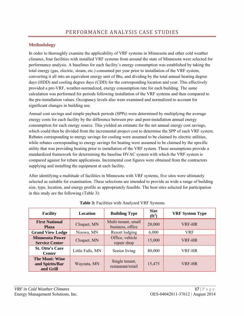
After identifying a multitude of facilities in Minnesota with VRF systems, five sites were ultimately selected as suitable for examination. These selections are intended to provide as wide a range of building size, type, location, and energy profile as appropriately feasible. The host sites selected for participation in this study are the following (Table 3):
Table 3: Facilities with Analyzed VRF Systems
Facility Location Building Type Size (ft2) VRF System Type
First National Plaza Cloquet, MN Multi-tenant, small
business, office 20,000 VRF-HR
Grand View Lodge Nisswa, MN Resort lodging 6,000 VRF Minnesota Power
Service Center Cloquet, MN Office, vehicle repair shop 15,000 VRF-HR
St. Otto’s Care Center Little Falls, MN Senior living 80,000 VRF-HR
The Muni: Wine and Spirits/Bar
and Grill Wayzata, MN Single tenant,
restaurant/retail 15,475 VRF-HR
VRF in Cold Weather Climates 17 | P a g e Energy Management Solutions, Inc. OES-04042011-37612 | August 2014

First National Plaza
Site Description
The First National Plaza building is located in downtown Cloquet, Minnesota. Originally a bank in the early 20th century, it has been retrofitted into a mini mall with several retail tenants on the first floor and offices bordering a large event room on the second floor. An air-cooled Mitsubishi Electric City Multi VRF system with heat recovery was installed in 2008. It replaced two large boilers, multiple window air conditioning (AC) units, and an outdoor evaporative condenser connected to a mini split system. There was no significant change in tenant occupancy from before or after installation. Compared to a new conventional HVAC system utilizing a single boiler and multiple window AC units, the incremental installed cost of this system was $138,000.
VRF System
The VRF system installed at First National Plaza consists of two air-cooled Mitsubishi Electric outdoor units (Figure 12) with model number PURY-P234TGMU-A. Each outdoor unit consists of two condensers and compressors and is connected to a BC controller with model number CMB-P1016NU-GA. Each BC controller is connected to 14 separate indoor units. In total, 28 indoor units with various model numbers are run by the outdoor units. Temperature set points, fan speed, and mode (heating or cooling) are all controlled from a central control system through proprietary Mitsubishi computer software. The system operates in heat recovery mode for the majority of the year by removing excess heat from several of the commercial tenants and distributing it to other areas of the building as needed. Please refer to Appendix B for spec sheets on the outdoor units.
The air-cooled condensing units were placed in a mechanical room with large vents to the outdoors. Due to the geographic location and low number of cooling degree days, the vents are left open for most of the year until the ambient temperature drops below the operating temperature of the condensing units—at which point the vents are closed and an electric resistance heat source is switched on to keep the mechanical room above the units’ minimum operating temperature of -4°F(-20°C). This configuration has allowed the building’s owner to completely eliminate the use of natural gas from the boilers and reliance upon the old conventional HVAC technology.
Figure 12: One of the two outdoor condensing units at First National Plaza in Cloquet, Minnesota. The units are located in a mechanical room within the building envelope where large ducts have been created
to supply plenty of ambient air. VRF in Cold Weather Climates 18 | P a g e Energy Management Solutions, Inc. OES-04042011-37612 | August 2014

Results
Figure 13 displays a chart of the building’s monthly energy consumption from 2006 through 2011. Table 4 provides a comparison for the total annual weather-normalized energy consumption from 2006 through 2011. The gray highlight over the 2008 data signifies transitionary data due to installation of the VRF system that year. Table 5 quantifies the resulting energy and cost savings.
Rebates from the electric and natural gas utilities were estimated to total just over $9,700 and reduced the SPP from 7.3 to 6.8 years. Calculations for the rebates incorporated nameplate data for both the conventional and VRF systems, assumed equivalent full load hours for cooling and heating, and applied specific rebate rates from the utility company claiming the associated savings. Detailed calculations showing how the estimations for rebates were determined are provided in Appendix B.
Figure 13: Monthly energy consumption of First National Plaza from 2006-2011
Table 4: 2006-2011 Total Annual Weather-Normalized Energy Consumption of First National Plaza
Year Electric Therms/Year
Natural Gas Therms/Year
Total Therms/Year
Total Therms/Year/HDD
Total Therms/Year/CDD
2006 1441 28000 29441 3.01 87.88 2007 3767 28000 31767 3.24 94.83 2008 9939 10728 20667 2.47 61.69 2009 4911 0 4911 0.51 13.72 2010 5173 0 5173 0.58 11.78 2011 6160 0 6160 0.67 14.26
*Note: 2008 provides transitionary data due to installation of the VRF system that year.
VRF in Cold Weather Climates 19 | P a g e Energy Management Solutions, Inc. OES-04042011-37612 | August 2014
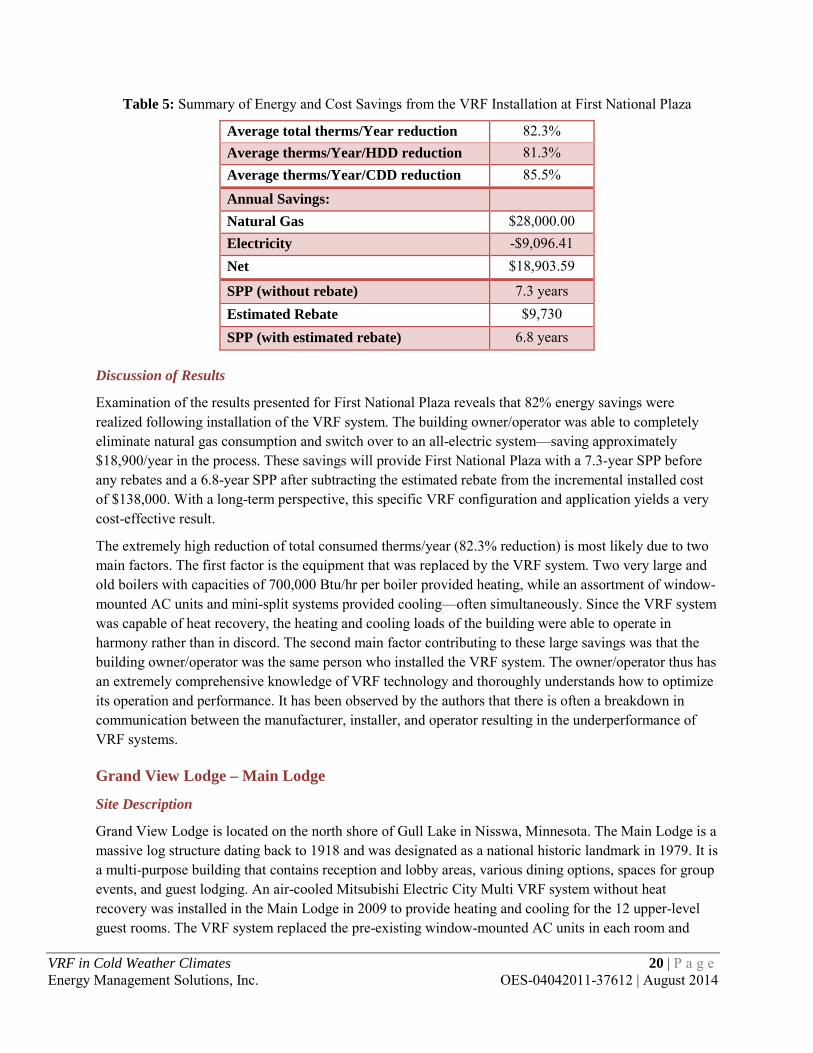
Table 5: Summary of Energy and Cost Savings from the VRF Installation at First National Plaza
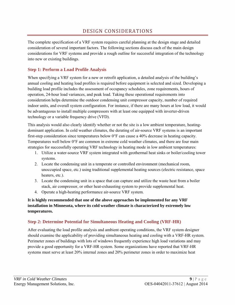
Average total therms/Year reduction 82.3% Average therms/Year/HDD reduction 81.3% Average therms/Year/CDD reduction 85.5%
Annual Savings:
Natural Gas $28,000.00 Electricity -$9,096.41 Net $18,903.59
SPP (without rebate) 7.3 years Estimated Rebate $9,730 SPP (with estimated rebate) 6.8 years
Discussion of Results
Examination of the results presented for First National Plaza reveals that 82% energy savings were realized following installation of the VRF system. The building owner/operator was able to completely eliminate natural gas consumption and switch over to an all-electric system—saving approximately $18,900/year in the process. These savings will provide First National Plaza with a 7.3-year SPP before any rebates and a 6.8-year SPP after subtracting the estimated rebate from the incremental installed cost of $138,000. With a long-term perspective, this specific VRF configuration and application yields a very cost-effective result.
The extremely high reduction of total consumed therms/year (82.3% reduction) is most likely due to two main factors. The first factor is the equipment that was replaced by the VRF system. Two very large and old boilers with capacities of 700,000 Btu/hr per boiler provided heating, while an assortment of window-mounted AC units and mini-split systems provided cooling—often simultaneously. Since the VRF system was capable of heat recovery, the heating and cooling loads of the building were able to operate in harmony rather than in discord. The second main factor contributing to these large savings was that the building owner/operator was the same person who installed the VRF system. The owner/operator thus has an extremely comprehensive knowledge of VRF technology and thoroughly understands how to optimize its operation and performance. It has been observed by the authors that there is often a breakdown in communication between the manufacturer, installer, and operator resulting in the underperformance of VRF systems.
Grand View Lodge – Main Lodge
Site Description
Grand View Lodge is located on the north shore of Gull Lake in Nisswa, Minnesota. The Main Lodge is a massive log structure dating back to 1918 and was designated as a national historic landmark in 1979. It is a multi-purpose building that contains reception and lobby areas, various dining options, spaces for group events, and guest lodging. An air-cooled Mitsubishi Electric City Multi VRF system without heat recovery was installed in the Main Lodge in 2009 to provide heating and cooling for the 12 upper-level guest rooms. The VRF system replaced the pre-existing window-mounted AC units in each room and
VRF in Cold Weather Climates 20 | P a g e Energy Management Solutions, Inc. OES-04042011-37612 | August 2014

mitigated the need to install electric resistance baseboard heating since none of the rooms were previously used during the winter months and didn’t contain a heating source. Because the rooms can now be heated throughout the winter, there was a significant increase in tenant occupancy from before installation. Compared to a new conventional HVAC system consisting of electric baseboard heating and new models of the pre-existing window-mounted AC units, the incremental installed cost of this system was estimated to be $22,500.
VRF System
The VRF system installed at the Main Lodge consists of two air-cooled Mitsubishi Electric outdoor units (Figure 14) with model number PUMY-P48NHMU. Each outdoor unit consists of one condenser and one compressor and is connected to a BC controller. Each BC controller is connected to 6 separate indoor units (Figure 15), each of which serve a single thermal zone. Temperature set points, fan speed, and mode (heating or cooling) can all be adjusted from the local controller in each guest’s room. The size and type of this VRF system did not require a centralized control system to be installed; and in the interest of simplifying operation of the system as much as possible, Grand View Lodge personnel decided to rely solely upon the local controllers for operation. As a result, there are no minimum or maximum set points programmed into a centralized controller to prevent dramatic temperature fluctuations. Fresh ventilation air is supplied through the operable windows in each room. Please refer to Appendix C for spec sheets on the outdoor units.
The air-cooled condensing units were placed on a rooftop adjacent to the rooms they serve. The system was originally designed for one outdoor unit to supply the six south-facing guest rooms while the other outdoor unit would supply the six north-facing guest rooms. This design scheme acknowledged the often distinctive thermal loads between north- and south-facing spaces and attempted to condition each general thermal load using a separate outdoor unit. However, this design was not fully implemented and each outdoor unit was ultimately installed to serve four rooms on one side of the building and two rooms on the other. During the shoulder months this final configuration frequently causes the outdoor units to be rendered temporarily inoperable since they are often requested to simultaneously provide both heating and cooling to the indoor units. The exceptionally low temperatures experienced by Grand View Lodge in the middle of winter required that the ceiling-concealed indoor units be coupled with electric resistant heaters to supplement the system once the ambient temperature pushes the derating factor below the system's capacity to heat the rooms or below its minimum operating temperature of 10°F (-12°C).
VRF in Cold Weather Climates 21 | P a g e Energy Management Solutions, Inc. OES-04042011-37612 | August 2014
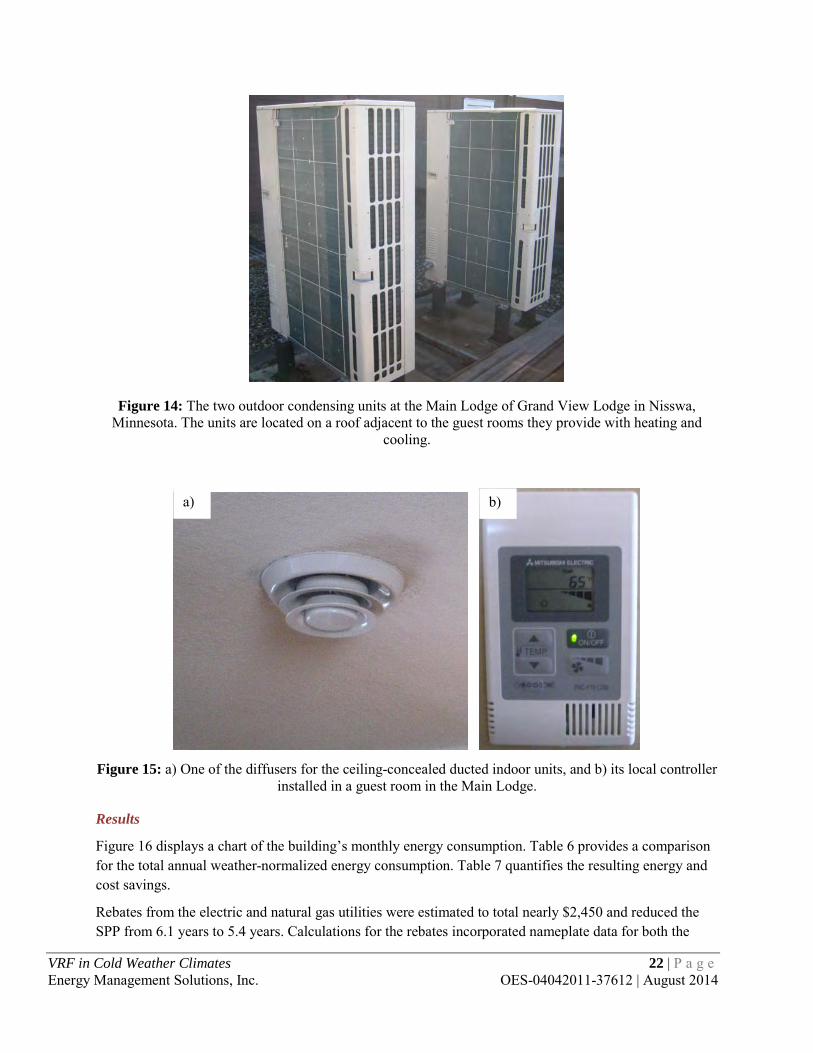
Figure 14: The two outdoor condensing units at the Main Lodge of Grand View Lodge in Nisswa,
Minnesota. The units are located on a roof adjacent to the guest rooms they provide with heating and cooling.
Figure 15: a) One of the diffusers for the ceiling-concealed ducted indoor units, and b) its local controller
installed in a guest room in the Main Lodge.
Results
Figure 16 displays a chart of the building’s monthly energy consumption. Table 6 provides a comparison for the total annual weather-normalized energy consumption. Table 7 quantifies the resulting energy and cost savings.
Rebates from the electric and natural gas utilities were estimated to total nearly $2,450 and reduced the SPP from 6.1 years to 5.4 years. Calculations for the rebates incorporated nameplate data for both the
b) a)
VRF in Cold Weather Climates 22 | P a g e Energy Management Solutions, Inc. OES-04042011-37612 | August 2014

conventional and VRF systems, assumed equivalent full load hours for cooling and heating, and applied specific rebate rates from the utility company claiming the associated savings. Detailed calculations showing how the estimations for rebates were determined are provided in Appendix C.
Figure 16: Monthly energy consumption per ft2 of Grand View Lodge from 2009-2013
Table 6: 2009-2013 Total Annual Normalized Energy Consumption of Grand View Lodge
Year
Electric Therms/Year
Natural Gas Therms/Year
Total Therms /Year
Total Therms /ft2/Year
Total Therms /ft2/Year/HDD
Total Therms /ft2/Year/CDD
2009 5,294 0 5,294 0.88 1.0x10⁻⁴ 3.6x10⁻³ 2010 5,403 0 5,403 0.90 1.1x10⁻⁴ 1.8x10⁻³ 2011 5,687 0 5,687 0.95 1.1x10⁻⁴ 1.8x10⁻³ 2012 5,939 0 5,939 0.99 1.3x10⁻⁴ 1.7x10⁻³ 2013 7,633 0 7,633 1.27 1.4x10⁻⁴ 2.5x10⁻³
Table 7: Summary of Energy and Cost Savings from the VRF Installation at Grand View Lodge
Average total therms/year reduction 68.97%
Annual Savings: Electricity $0.62/ft2
$3,711.82
SPP (without rebate) 6.1 years Estimated Rebate $2,450 SPP (with estimated rebate) 5.4 years
VRF in Cold Weather Climates 23 | P a g e Energy Management Solutions, Inc. OES-04042011-37612 | August 2014

Discussion of Results
Upon examination of the results presented in Figure 16, Table 6, and Table 7 for Grand View Lodge it can be seen that the Energy Use Index (EUI), total average therms/ft2/year, was roughly 69% lower than the window A/C units and electric strip heat that would have been installed. It should be noted that excessively cold weather in 2013 was responsible for higher than average energy usage. Impact of weather is more of a theoretical discussion for this facility, as energy usage is often dictated by the level of occupancy and the behavior of the occupants, in addition to weather. Disproportionately higher levels of occupancy during extreme cold or heat can have an extreme effect on the usage. This is very noticeable in a setting such as Grand View Lodge where occupants are partaking in outdoor activities. Grand View Lodge’s VRF system was estimated to provide net annual savings of $3,704/year. This correlates to a 6.1-year payback without rebates, and 5.4 years after estimated rebates are subtracted from the estimated incremental installed cost of $22,500. With a long-term perspective and expected building occupancy of several decades this specific VRF configuration and application appears to yield a very cost-effective result.
Minnesota Power Cloquet Service Center
Site Description
The Minnesota Power Cloquet Service Center (MPCSC) is located on the southeast side of Cloquet, Minnesota. It was originally built in the late 1970s and is a single-story building consisting of offices, materials storage, and garages for service vehicles. An air-cooled Daikin AC (Americas), Inc., VRV18 system with heat recovery was installed in 2010 that replaced electric resistance heating and a packaged air-cooled DX AC system. There was no significant change in tenant occupancy from before or after installation. Compared to a new conventional HVAC system consisting of new models of the previously existing equipment, the incremental installed cost of this system was estimated to be $106,000.
VRV System
The VRV system installed at MPCSC consists of a single Daikin outdoor unit with model number REYQ192PAYD. The outdoor unit consists of two condensers and compressors and is connected to a central control system. This system controls 11 separate indoor units of various model numbers. Each serves a unique thermal zone and is located in the air plenum above the ceiling tiles. The indoor units only provide heating and cooling to the office portion of the building and operate in conjunction with a DOAS and heat recovery ventilator (HRV) to efficiently meet the outdoor air requirements of that space. Temperature set points, fan speed, and mode (heating or cooling) are all controlled from the central control system, which is integrated with a Johnson Controls BMS. The system operates in heat recovery mode for the majority of the year by removing excess heat from a small data storage room and distributing it to other areas of the building during the heating season. Please refer to Appendix C for spec sheets on the outdoor condensing units.
The air-cooled condensing units were placed in an outdoor, open-air shed that protects the units from precipitation, but does not provide any temperature control. Due to the geographic location and extremely cold temperatures experienced in the middle of the winter, the building still has electric resistance heat to supplement the VRV system once the ambient temperature pushes the derating factor below the system’s
18 Variable Refrigerant Volume (VRV) is Daikin Industries’ proprietary term for VRF systems.
VRF in Cold Weather Climates 24 | P a g e Energy Management Solutions, Inc. OES-04042011-37612 | August 2014
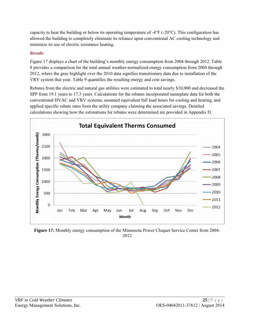
capacity to heat the building or below its operating temperature of -4°F (-20°C). This configuration has allowed the building to completely eliminate its reliance upon conventional AC cooling technology and minimize its use of electric resistance heating.
Results
Figure 17 displays a chart of the building’s monthly energy consumption from 2004 through 2012. Table 8 provides a comparison for the total annual weather-normalized energy consumption from 2004 through 2012, where the gray highlight over the 2010 data signifies transitionary data due to installation of the VRV system that year. Table 9 quantifies the resulting energy and cost savings.
Rebates from the electric and natural gas utilities were estimated to total nearly $10,000 and decreased the SPP from 19.1 years to 17.3 years. Calculations for the rebates incorporated nameplate data for both the conventional HVAC and VRV systems, assumed equivalent full load hours for cooling and heating, and applied specific rebate rates from the utility company claiming the associated savings. Detailed calculations showing how the estimations for rebates were determined are provided in Appendix D.
Figure 17: Monthly energy consumption of the Minnesota Power Cloquet Service Center from 2004-
2012
VRF in Cold Weather Climates 25 | P a g e Energy Management Solutions, Inc. OES-04042011-37612 | August 2014

Table 8: 2004-2012 Total Annual Weather-Normalized Energy Consumption of the Minnesota Power Cloquet Service Center
Year Electric Therms/Year
Natural Gas Therms/Year
Total Therms/Year
Total Therms/Year/HDD
Total Therms/Year/CDD
2004 14085 0 14085 1.44 42.05 2005 14963 0 14963 1.53 44.67 2006 14577 0 14577 1.49 43.51 2007 13954 0 13954 1.43 41.65 2008 17374 0 17374 1.77 51.86 2009 13653 0 13653 1.42 38.14 2010 13155 0 13155 1.47 29.97 2011 13031 0 13031 1.42 30.16 2012 10910 0 10910 1.50 14.82
*Note: 2010 provides transitionary data due to installation of the VRF system that year.
Table 9: Summary of Energy and Cost Savings from the VRV Installation at the Minnesota Power Cloquet Service Center
Average total therms/Year reduction 18.9% Average therms/Year/HDD reduction 3.5% Average therms/Year/CDD reduction 48.5%
Annual Savings:
Natural Gas $0.00 Electricity $5,561 Net $5,561
SPP (without rebate) 19.1 years Estimated Rebate $9,970 SPP (with estimated rebate) 17.3 years
Discussion of Results
The results presented for MPCSC show that 19% percent energy savings were realized following installation of the VRV system. The building owner and occupants previously relied upon electric baseboard heating and thus the energy savings were solely due to reduction in electricity consumption—saving roughly $5,560/year. These savings will provide MPCSC with a 19-year SPP before any rebates and a 17-year SPP after subtracting the estimated rebate from the incremental installed cost of $106,000. This implies that from a purely financial perspective, the VRV installation at MPCSC will not be a cost-effective project, although other factors might weigh into the utility’s assessment of the project’s success.
Following an analysis of the system’s configuration and discussions with operators of the MPCSC building, two major issues were discovered that contributed to the lower-than-expected energy savings and high SPP. The first concerns occupant behavior in 2011 – during the first year the VRV system was operated. Not only were a certain group of workers routinely leaving doors open between the service
VRF in Cold Weather Climates 26 | P a g e Energy Management Solutions, Inc. OES-04042011-37612 | August 2014
truck garages and the VRV-conditioned office space, but the facility staff and maintenance personnel had a hard time understanding how to integrate and utilize the technology. This forced the VRV system to run more frequently than anticipated/designed and resulted in much higher energy consumption than necessary.
The location of the air-cooled condensing units in an open-air, outdoor shed that does not provide any temperature control is the second major issue contributing to the system’s poor cost-effectiveness. As recommended on page 8 under Step 1: Perform a Load Profile Analysis, air-cooled condensing units installed in cold-weather climates should be located in temperate or controlled environments such as a mechanical room or other unoccupied space where supplemental heating sources can maintain the space above the condensing units’ minimum operating temperature. Not only would this allow MPCSC’s VRV system to run year-round, it also would reduce the derating factor and allow the condensing units to operate at a lower percent of their full-load capacity. If these two issues can be resolved, MPCSC will likely see a significant improvement in the energy savings and SPP from its VRV system.
St. Otto’s Care Center
Site Description
St. Otto’s Care Center (SOCC) is located on the southern edge of Little Falls, Minnesota, immediately adjacent to St. Gabriel’s Hospital. It was originally built in the late 1960s and is a three-story nursing home consisting of three wings with 93 total individual rooms. An air-cooled Mitsubishi Electric City Multi VRF system with heat recovery was installed in late 2010/early 2011 that eliminated window-mounted AC units in each room. It mostly offset the use of radiant electric heaters in each room and a chiller/boiler combination serving the first floor and hallways. There was no significant change in tenant occupancy from before or after installation. Compared to a new conventional HVAC system utilizing rooftop units, the incremental installed cost of this system was estimated to be $240,000.
VRF System
The VRF system installed at SOCC consists of six air-cooled Mitsubishi Electric outdoor units (Figure 18) with model number PURY-P96TGMU-A. Each outdoor unit consists of one condenser and compressor and is connected to a BC controller and Sub BC controller with model numbers CMB-P1010NU-GA and CMB-P108NU-GB, respectively. Each BC/Sub BC controller is connected to 16 or 17 separate indoor units that each serve a single room. In total, 98 indoor units with model number PMFY-P06NBMU-E are run by the outdoor units. Temperature set points, fan speed, and mode (heating or cooling) can all be adjusted from local controls in each resident’s room through proprietary Mitsubishi computer software. Minimum and maximum set points were programmed into a centralized control system to prevent dramatic fluctuations. The system operates in heat recovery mode for the majority of the year by removing excess heat from rooms with low set points and distributing it to other areas of the building and resident rooms as needed. An independent ventilation system is utilized to supply the required amount of fresh air to the space. Please refer to Appendix E for spec sheets on the outdoor units.
The air-cooled condensing units were placed on the rooftops of the wings they serve. Two outdoor condensing units serve each wing. Due to the geographic location and extremely cold temperatures experienced in the middle of the winter, the system has been coupled with radiant electric heaters and steam heat through a district energy system owned by the adjacent St. Gabriel’s Hospital to supplement the VRF system once the ambient temperature pushes the derating factor below the system’s capacity to
VRF in Cold Weather Climates 27 | P a g e Energy Management Solutions, Inc. OES-04042011-37612 | August 2014

heat the building or below its operating temperature of -4°F (-20°C). This configuration has allowed SOCC to dramatically reduce its reliance upon this district energy system.
Figure 18: Two of the six outdoor condensing units at St. Otto’s Care Center in Little Falls, MN. The
units are located on the roof above the wing of rooms they provide with heating and cooling.
Results
Figure 19 displays a chart of the building’s monthly energy consumption from 2008 through 2012. Table 10 provides a comparison for the total annual weather-normalized energy consumption from 2008 through 2012, where the gray highlight over the 2010/2011 data signifies transitionary data due to installation of the VRF system those years. Table 11 quantifies the resulting energy and cost savings.
Rebates from the electric and natural gas utilities were estimated to total nearly $23,300 and reduced the SPP from 16.2 years to 14.6 years. Calculations for the rebates incorporated nameplate data for both the conventional and VRF systems, assumed equivalent full load hours for cooling and heating, and applied specific rebate rates from the utility company claiming the associated savings. Detailed calculations showing how the estimations for rebates were determined are provided in Appendix E.
VRF in Cold Weather Climates 28 | P a g e Energy Management Solutions, Inc. OES-04042011-37612 | August 2014

Figure 19: Monthly energy consumption of St. Otto’s Care Center from 2008-2012
Table 10: 2008-2012 Total Annual Weather-Normalized Energy Consumption of St. Otto’s Care Center
Year Electric Therms/Year
Natural Gas Therms/Year
Total Therms/Year
Total Therms/Year/HDD
Total Therms/Year/CDD
2008 39,644 67,420 107,064 10.93 319.59 2009 31,122 31,122 105,792 11.08 295.51 2010 36,960 67,083 104,043 11.55 237.00 2011 37,970 66,502 104,473 11.00 241.83 2012 40,735 54,571 95,307 10.62 173.84
*Note: 2010/2011 provides transitionary data due to installation of the VRF system those years
Table 11: Summary of Energy and Cost Savings from the VRF Installation at St. Otto’s Care Center
Average total therms/year reduction 10.4% Average therms/year/HDD reduction 3.5% Average therms/year/CDD reduction 43.5%
Annual Savings:
Natural Gas $9,132 Electricity $5,708 Net $14,840
SPP (without rebate) 16.2 years Estimated Rebate $23,250 SPP (with estimated rebate) 14.6 years
VRF in Cold Weather Climates 29 | P a g e Energy Management Solutions, Inc. OES-04042011-37612 | August 2014

Discussion of Results
Examination of the results for SOCC reveals that 10.4% energy savings were realized following installation of the VRF system. The building owner was able to completely eliminate the use of radiant electric heaters and window-mounted AC units in each of the residents’ rooms, while also drastically cutting down on the amount of steam used for heating on the first floor and in the hallways. This was estimated to be generating savings of roughly $14,800/year. These savings will provide SOCC with a 16.2-year SPP before any rebates and a 14.6-year SPP after the estimated rebate is subtracted from the incremental installed cost of $240,000. With a long-term perspective, this specific VRF configuration and application does not appear to yield a cost-effective result. However, the greatly increased comfort level provided to the residents is a huge factor and should be taken into consideration.
The long and unattractive payback for SOCC’s VRF system is initially puzzling since both theory and the industry would suggest this to be an appropriate and effective application for VRF technology. However, further analysis of the facility’s energy bills revealed that SOCC experienced a 27% increase in its electricity consumption rate ($/kWh) between pre- and post-installation of its Mitsubishi VRF system. If SOCC’s electricity rate had remained constant, the estimated net annual savings would have been approximately $18,800/year—yielding a 12.8-year SPP before rebates and 11.5-year SPP after estimated rebates are applied.
Another factor that contributes to this high SPP is SOCC’s placement of the air-cooled condensing units on the rooftop in unprotected, outdoor locations that do not provide any temperature control or protection from precipitation. This is a similar design flaw to the VRV system installed at MPCSC and the recommended solution is identical: locate the air-cooled condensing units in temperate or controlled environments where supplemental heating sources can maintain the space above the condensing units’ minimum operating temperature. Not only will this allow SOCC’s VRF system to run year round, it will also reduce the derating factor and allow the condensing units to operate at a lower percent of their full-load capacity. Installation of small rooftop penthouses around each pair of condensing units is anticipated to significantly reduce this project’s SPP.
The Muni: Wayzata Wine and Spirits/Bar and Grill
Site Description
The Muni: Wayzata Wine and Spirits is located on the north end of Lake Minnetonka in downtown Wayzata, Minnesota. It originally began operating in 1947 as a municipal liquor store and restaurant and in the beginning of 2011 it moved into a new facility. An air-cooled Mitsubishi Electric City Multi VRF system with heat recovery was installed in the new building instead of a forced air and electric baseboard heating system and a packaged air-cooled DX AC system. The new facility slightly more than doubled the square footage occupied by the business. Compared to the alternative new HVAC system utilizing conventional technology, the incremental installed cost of this system was estimated to be $128,600.
VRF System
The VRF system installed at The Muni consists of two air-cooled Mitsubishi Electric outdoor units (Figure 20) with model number PURY-P144TJMU-A. Each outdoor unit consists of two condensers and compressors and is connected to a BC controller. Each BC controller is connected to 10 separate indoor units (Figure 21a), which serve three to four large thermal zones. The indoor units provide simultaneous
VRF in Cold Weather Climates 30 | P a g e Energy Management Solutions, Inc. OES-04042011-37612 | August 2014

heating and cooling to both the liquor store and restaurant and operate in conjunction with a chiller for the coolers in the liquor store and a DOAS with ERVs to efficiently meet the outdoor air requirements of each zone. Temperature set points are the only parameter that can be controlled from local controls (Figure 21b) for each indoor unit. Minimum and maximum set points, fan speed, and mode (heating, cooling, or simultaneous) are handled by a centralized control system. The system operates in heat recovery mode for a majority of the year since it serves large open zones where occupancy and solar insolation can vary widely. Please refer to Appendix F for spec sheets on the outdoor condensing units.
The air-cooled condensing units were placed in a temperature-controlled mechanical room within the building envelope where large louvers provide the space with outside air. One outdoor condensing unit serves the restaurant while the other outdoor unit serves the liquor store. Chillers that provide refrigeration for the liquor store, exhaust their heat into the mechanical room, which the outdoor condensing units are then able to utilize for heating during periods when net heating is required. Due to the geographic location and low number of cooling degree days, the louvers are left open for most of the year until the mechanical room’s temperature falls below 50°F—at which point the louvers are closed and an electric resistance heat source is switched on to help maintain the mechanical room at or above 50°F. This keeps the derating factor for the condensing units very low and does not allow it to have a large impact on the system’s heating capacity.
Figure 20: One of the two outdoor condensing units at The Muni in Wayzata, Minnesota. The units are located in a temperature-controlled mechanical room within the building envelope where large louvers
provide the space with outside air depending on the ambient and room temperatures.
VRF in Cold Weather Climates 31 | P a g e Energy Management Solutions, Inc. OES-04042011-37612 | August 2014

Figure 21: a) One of the cassette-style indoor units and b) its local controller installed in the restaurant
portion of The Muni
Results
Figure 22 displays a chart of the building’s monthly energy consumption from 2009 through 2012. Table 12 provides a comparison for the total annual weather-normalized energy consumption from 2009 through 2012, where the gray highlight over the 2011 data signifies transitionary data due to installation of the VRF system that year. Table 13 quantifies the resulting energy and cost savings.
Rebates from the electric and natural gas utilities were estimated to total nearly $8,000 and reduced the SPP from 5.1 years to 4.8 years. Calculations for the rebates incorporated nameplate data for both the conventional and VRF systems, assumed equivalent full load hours for cooling and heating, and applied specific rebate rates from the utility company claiming the associated savings. Detailed calculations showing how the estimations for rebates were determined are provided in Appendix F.
Figure 22: Monthly energy consumption per ft2 of The Muni from 2009-2012
VRF in Cold Weather Climates 32 | P a g e Energy Management Solutions, Inc. OES-04042011-37612 | August 2014
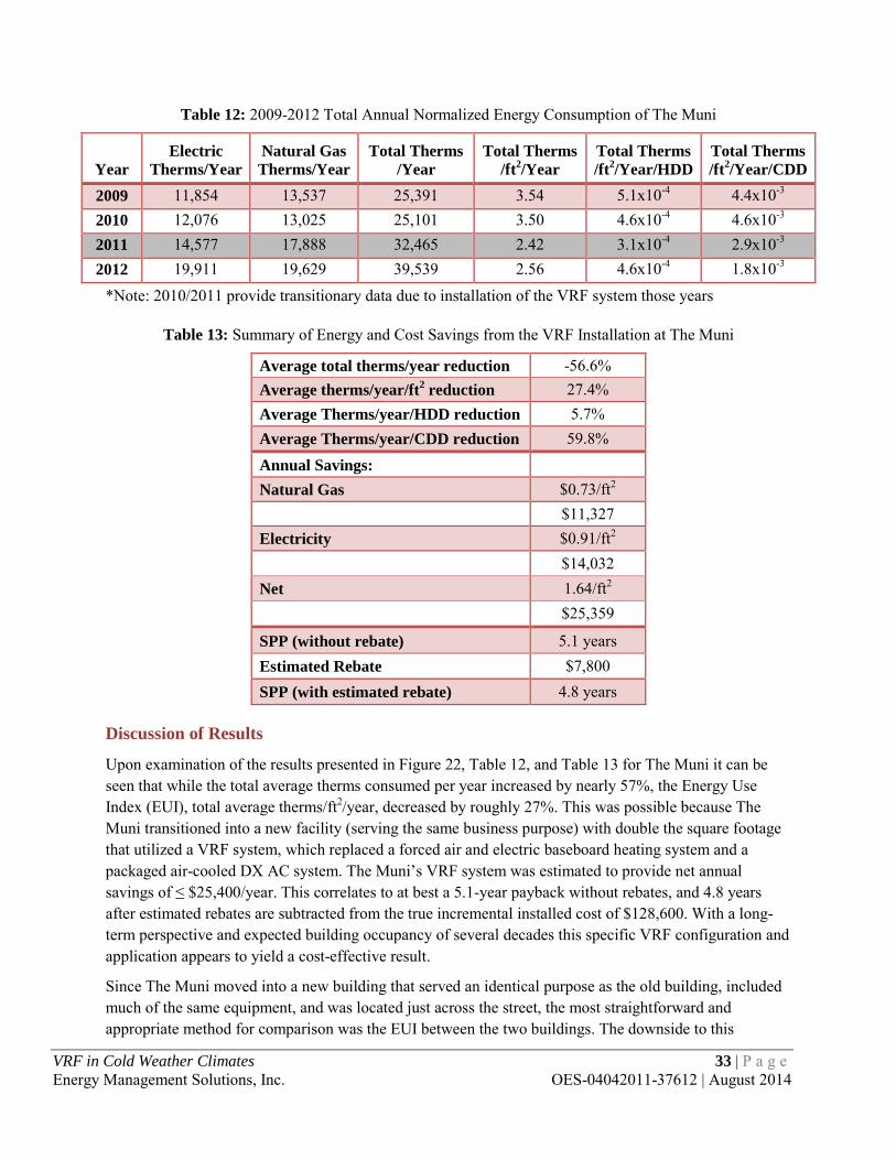
Table 12: 2009-2012 Total Annual Normalized Energy Consumption of The Muni
Year
Electric Therms/Year
Natural Gas Therms/Year
Total Therms /Year
Total Therms /ft2/Year
Total Therms /ft2/Year/HDD
Total Therms /ft2/Year/CDD
2009 11,854 13,537 25,391 3.54 5.1x10⁻⁴ 4.4x10⁻³ 2010 12,076 13,025 25,101 3.50 4.6x10⁻⁴ 4.6x10⁻³ 2011 14,577 17,888 32,465 2.42 3.1x10⁻⁴ 2.9x10⁻³ 2012 19,911 19,629 39,539 2.56 4.6x10⁻⁴ 1.8x10⁻³
*Note: 2010/2011 provide transitionary data due to installation of the VRF system those years
Table 13: Summary of Energy and Cost Savings from the VRF Installation at The Muni
Average total therms/year reduction -56.6% Average therms/year/ft2 reduction 27.4% Average Therms/year/HDD reduction 5.7% Average Therms/year/CDD reduction 59.8%
Annual Savings: Natural Gas $0.73/ft2
$11,327 Electricity $0.91/ft2
$14,032 Net 1.64/ft2
$25,359
SPP (without rebate) 5.1 years Estimated Rebate $7,800 SPP (with estimated rebate) 4.8 years
Discussion of Results
Upon examination of the results presented in Figure 22, Table 12, and Table 13 for The Muni it can be seen that while the total average therms consumed per year increased by nearly 57%, the Energy Use Index (EUI), total average therms/ft2/year, decreased by roughly 27%. This was possible because The Muni transitioned into a new facility (serving the same business purpose) with double the square footage that utilized a VRF system, which replaced a forced air and electric baseboard heating system and a packaged air-cooled DX AC system. The Muni’s VRF system was estimated to provide net annual savings of ≤ $25,400/year. This correlates to at best a 5.1-year payback without rebates, and 4.8 years after estimated rebates are subtracted from the true incremental installed cost of $128,600. With a long-term perspective and expected building occupancy of several decades this specific VRF configuration and application appears to yield a cost-effective result.
Since The Muni moved into a new building that served an identical purpose as the old building, included much of the same equipment, and was located just across the street, the most straightforward and appropriate method for comparison was the EUI between the two buildings. The downside to this
VRF in Cold Weather Climates 33 | P a g e Energy Management Solutions, Inc. OES-04042011-37612 | August 2014

approach is its inability to incorporate the change in building envelope design, construction, and orientation. Detailed building modeling software such as eQUEST19, DOE-220, or Trace 70021 is the only way to accurately estimate the effects these changes will have on the building’s energy consumption. Such an analysis, however, would exceed the scope of this study, and its lack of inclusion introduces an upper limit in the energy and cost savings obtained for this particular VRF system.
19 The latest version of eQUEST is available on the eQUEST page of the DOE website (http://doe2.com/equest/) 20 The latest version of DOE-2 is available on the DOE2 page of the DOE website (http://doe2.com/DOE2/) 21 The latest version of Trace 700 is available on the Trane website (http://www.trane.com/Commercial/Dna/View.aspx?i=1136)
VRF in Cold Weather Climates 34 | P a g e Energy Management Solutions, Inc. OES-04042011-37612 | August 2014

INCLUSION IN UTILITY DSM PROGRAMS
Results from the four preceding case studies should be interpreted by utilities as substantial yet highly site-specific for inclusion in their demand side management (DSM) programs The case studies provided a wide range of energy and cost savings that, when taken individually, indicate certain configurations of VRF technology can be highly cost-effective in cold weather climates. Taken as a whole, however, the results indicate that a custom approach will be necessary for the technology to be successfully offered as part of a DSM program.
The limitations this study faced with examining VRF systems were a combination of inherent challenges, poor and inadequate sample size, and a methodological shortcoming. The inherent challenges with examining VRF technology are that its effectiveness is entirely dependent upon the design, application, and operation of the system. No two systems are identical and few, if any, are operated by the same personnel. These factors imbue VRF technology with an inherent variability that makes it extremely difficult to generalize its effectiveness.
Another limitation this study faced was the small sample size of applicable VRF systems in Minnesota. The vast majority of VRF systems the authors investigated for inclusion in this report were either: 1) part of new construction, which makes it nearly impossible to create a baseline against which to compare the VRF technology without the use of building modeling software; or 2) improperly utilized by continuously operating in cooling-only mode year round for data closets or other constant internal loads). This left a small sample of properly applied and operated retrofit VRF systems that provided measurable energy consumption baselines.
The methodological shortcoming was the report’s lack of development of a calibrated energy model for each host site. Calibrated energy models would have helped to quantify and incorporate the effect on energy use due to changes in building envelope, design, construction, and orientation for The Muni case study. They would also have provided the opportunity to accurately examine the effectiveness of VRF systems in new construction—thereby greatly expanding the applicable sample size. The authors believe this to be the key shortcoming of this study and recommend future studies of VRF technology address this need.
With the aforementioned issues in mind, we reiterate that VRF technology is nonetheless worth considering in cold weather applications. This conclusion is drawn from two primary strategies for successful implementation: water-cooled condensing units and air-cooled condensing units located in temperate or controlled environments coupled with supplemental heating sources. Both strategies work to reduce the impact of the derating factor and allow a system to efficiently operate throughout the year.
Determining the baseline condition from which to compare a new VRF system against is a critical issue for utility-sponsored projects. The complex nature of an entire HVAC system redesign indicates that a custom approach is needed as the baseline must be determined on a case-by-case basis. For existing HVAC equipment beyond its useful life, it would be most suitable to use new models of the previously installed equipment for the baseline. For new construction projects and major renovations, energy savings should be quantified based on modeling using whichever new standard HVAC equipment best lends itself to the application and building type. However, for retrofits involving existing HVAC equipment well within its expected lifetime (as was the situation for all five case studies), then the existing equipment should be used as the baseline. This last recommendation stems from the reality that a newer, functioning
VRF in Cold Weather Climates 35 | P a g e Energy Management Solutions, Inc. OES-04042011-37612 | August 2014

HVAC system would not otherwise be replaced; and that converting from conventional HVAC technology to VRF technology requires a complete system redesign.
Once the appropriate baseline condition has been determined, a standardized methodology is needed for allocating the resulting energy savings. It is recommended that energy savings for cooling be allocated to electric utilities, while energy savings for heating purposes be allocated to the specific utility that was providing heating prior to installation of the VRF system. As a result, it is expected that the often problematic issue of fuel switching will be alleviated. Peak demand savings, albeit not a major factor, can then be determined once the energy savings have been allocated. During the cooling season, the energy efficiency ratio (EER) of most new VRF systems is comparable to the minimum ENERGY STAR product criteria for conventional AC equipment; and since peak cooling loads tend to coincide with peak electric utility loads some peak savings are likely to be realized. During the peak of the heating season, the coefficient of performance (COP) of most new VRF systems is 2.5-4 times greater than heating with conventional sources such as electric resistance and natural gas. Since peak heating loads occur at night they closely coincide with peak gas utility loads, but do not align themselves with peak electric utility loads.
It is also expected that operation and maintenance (O&M) savings will often be examined and quantified for VRF systems replacing conventional HVAC technology. This is primarily due to the inherently more centralized nature of VRF systems and the opportunity for O&M personnel to perform their work on a single or small number of centrally located units rather than a dispersed network of miscellaneous HVAC equipment. O&M savings may be quantified by annualizing and combining repaired/replaced equipment costs with all associated O&M labor costs. Should any loss of revenue regularly result from HVAC equipment downtimes, then this cost should be included in O&M savings as well.
Through the course of this study, it also became apparent that the effectiveness of VRF technology is inherently too variable and site specific to succeed as a prescriptive project. Therefore the authors recommend its immediate incorporation into utility DSM programs as a custom project with the following guidelines:
1) Outdoor condensing units must be either: a. Water-cooled. b. Air-cooled and located in temperate or controlled environments with supplemental
heating sources. 2) M&V is best accomplished using whole building energy consumption data, converted to therms,
annualized, and normalized for weather. If necessary, data should also be normalized for other variables such as occupancy, gross square footage, etc.
3) VRF equipment must be certified in accordance with the latest edition of ANSI/AHRI Standard 1230, Performance Rating of Variable Refrigerant Flow (VRF) Multi-Split Air-Conditioning and Heat Pump Equipment.
4) VRF equipment must be NRTL listed. 5) VRF system should be installed and commissioned by personnel who are trained and certified for
that particular manufacturer.
VRF technology is new enough to the U.S. that none of the systems is this country have reached their expected end of life. However, since VRF systems have enjoyed widespread acceptance in Japan and Europe for more than 20 years, an excellent historical record exists for determining appropriate lifetimes.
VRF in Cold Weather Climates 36 | P a g e Energy Management Solutions, Inc. OES-04042011-37612 | August 2014

Most VRF system manufacturers with significant market penetration outside of the U.S. claim 20 to 25 years for water-source systems and 15 to 20 years for air-source systems – provided that recommended maintenance is routinely performed.22
22 "Chapter 18: Variable Refrigerant Flow." 2012 ASHRAE Handbook - HVAC Systems and Equipment. Inch-Pound Edition. Atlanta: ASHRAE, 2012. Print.
VRF in Cold Weather Climates 37 | P a g e Energy Management Solutions, Inc. OES-04042011-37612 | August 2014

CONCLUSIONS
Conversations with facility owners, managers, and occupants of the host sites as well as a wide range of studies researched for this report have helped identify a number of important conclusions regarding the application of VRF systems in the U.S. These issues range from energy and economics to system installation and operation. As building owners, designers, facility managers, and manufacturers contemplate, integrate, and develop VRF systems in the U.S., they would be well served to intensify and coordinate their education and training efforts with VRF manufacturers to address and highlight these issues, which are discussed in the following sections.
Advantages
Comfort: VRF technology is perfectly suited to individually provide heating and cooling to large numbers of thermal zones within a single building envelope. By continuously modulating the amount of refrigerant supplied to each indoor unit, the system can quickly adjust to meet the loads of each zone and keep temperature fluctuations to a minimum. The technology is also capable of providing simultaneous heating and cooling—ensuring that occupants can be comfortable year round.
Energy Efficiency: The outdoor units utilize variable speed compressors with 10% to 100% capacity ranges to precisely match and control the necessary refrigerant circulation amount required by the system’s net heating or cooling load. This modulated flow control saves energy by not having to stop and start the motor multiple times a day. Field testing by multiple manufacturers has indicated that this reduces energy use by 30% to 40% compared to traditional reciprocating-type or rotary compressors. VRF technology also has the capability for heat recovery (VRF-HR) that provides simultaneous heating and cooling. VRF-HR offers the most efficient configuration of VRF technology and further increases the energy savings compared to conventional HVAC technology.
Installation Advantages: By utilizing refrigerant piping and minimizing the need for ductwork, VRF systems are easier to install and are less invasive than conventional HVAC systems. Installers simply need to cut holes about 3” in diameter to run the piping for the system and 9” ductwork to meet the fresh air requirements (compared to 40”+ ductwork for conventional air systems). All the lightweight components can fit into an elevator for installation in ceilings, mezzanines, and on rooftops. The smaller footprint of the VRF systems allows for more usable space in a building. In addition, VRF systems enable phased installations and commissioning—allowing portions of the system to begin functioning while construction is still underway, unlike large duct or chiller systems, which cannot function until the construction project is completed.
Reliability: Because each indoor unit is controlled individually, VRF systems can operate continuously even if failure occurs at an indoor unit. The outdoor units have also been designed to operate continuously should there be compressor failure. Advances in VRF technology are nearing ‘plug and play’ commissioning and the lack of water pumps or air ducts leads to reductions in time spent on maintenance. Scheduled maintenance on VRF systems mainly consists of changing filters and cleaning coils.
Design Flexibility: The modular concept of VRF technology allows for easy adaptation to future building expansion or reconfiguration projects. If additional capacity is required in the future, supplementary outdoor and indoor units may be incorporated into the original system as the additional capacity is needed. Another design approach is to initially design the outdoor unit(s) to be slightly oversized in order
VRF in Cold Weather Climates 38 | P a g e Energy Management Solutions, Inc. OES-04042011-37612 | August 2014

to accommodate the eventual addition of indoor units. If there are no plans for future expansion, oversizing should be avoided in order to minimize cycling of the compressor(s) in the outdoor unit(s).
Reduced Noise Levels: VRF systems operate at significantly lower noise levels than conventional split systems. Noise levels have been reduced by almost 5dB at 1 meter—which has been achieved mainly due to outdoor units running at partial load rather than cycling between 0% and 100%. This characteristic is advantageous for facilities that require minimal disruption, such as places of worship, libraries, hospitals, research labs, and others.
LEED Points: VRF systems have the largest effect on energy use for Leadership in Energy and Environmental Design (LEED) certification. They may help earn points in a wide range of energy efficiency categories. VRF systems can also help obtain points for indoor air quality (IAQ).
Energy Sub-metering: By placing an electric meter on each indoor condensing unit, sub-metering with VRF systems becomes relatively simple and inexpensive. This is a very sought-after feature for multi-tenant buildings where energy costs are charged explicitly to each tenant rather than being hidden in overall leasing costs.23
Drawbacks and Challenges
First Costs: In many studies, complete installation costs for VRF systems have been estimated to be between 5% and 20% higher than that of comparable, conventional systems. Building owners often do not have much of an incentive to accept higher first costs even if payback periods are short. Much of this initial cost differential stems from contractors’ unfamiliarity with the product and bidding a higher installation cost than necessary. As experience and comfort level with the technology increases, first costs should converge with those for conventional HVAC technology.
Refrigerant Piping Design Criteria: Specific distance criteria restrict the length of refrigerant piping between the condensing unit and the evaporators. Distance needs to be taken into account for each stretch of piping because the compressors have a limited ability for overcoming the pressure drop in the system and maintaining proper oil return. Each manufacturer has its own maximum length specifications and it is important that the designer be aware of these limits.
Compliance with ASHRAE Standards: Because the primary working fluid in VRF technology is refrigerant, designers and contractors need to ensure compliance with ASHRAE Standard 15-2010 and ASHRAE Standard 34-2010 regarding the safe application of refrigeration-based systems in occupied spaces. VRF systems have a magnified concern compared to traditional DX systems because of their interconnected refrigerant piping and the theoretical potential for discharging a large quantity of refrigerant into a small indoor space in the unlikely event of a catastrophic leak or failure. In smaller confined spaces, a large leak of refrigerant can cause oxygen depletion. In facilities with large piping networks, compliance can be more difficult. Another standard that must meet compliance is ASHRAE Standard 62.1-2010, which addresses fresh air requirements. This has proven to be the most challenging standard for VRF systems to meet because VRF systems do not provide fresh air ventilation on their own and, therefore, must be integrated with a separate fresh air ventilation strategy. A fresh air ventilation strategy must be developed alongside the VRF system to comply with ASHRAE Standard 62.1-2010.
23 Bhatia, A. "HVAC Variable Refrigerant Flow Systems." Course No: M03-014. Continuing Education and Development, Inc. 24 Sep 2012. Reading.
VRF in Cold Weather Climates 39 | P a g e Energy Management Solutions, Inc. OES-04042011-37612 | August 2014

Personnel Training: Installers, operators, and maintenance technicians all need to be trained on how to properly implement VRF systems and utilize them to their fullest potential. However, these personnel often view this is as a time-consuming and unnecessary requirement since they have usually already completed training on the various conventional HVAC technologies.
Proprietary Components: VRF systems are completely proprietary systems. Each manufacturer has its own unique components, control systems, piping configurations, and heat transfer technology. They are designed not to be integrated with systems from other manufacturers. This makes it difficult if not impossible to switch between VRF technologies and forces brand loyalty even if it is not desired.
Lack of Familiarity and Manufacturer Support: VRF technology is still rather new to the U.S. and has not enjoyed widespread implementation throughout the country’s various climates. There are specific applications where VRF systems work incredibly well and others where it will not work well at all. Manufacturers, contractors, and owners may need education about these systems and their potential. The establishment of a certification program and product directory by the Air-Conditioning, Heating, and Refrigeration Institute (AHRI) has provided the industry with a highly useful, standardized method for comparing various VRF technologies and is crucial to helping the technology gain a foothold in the industry.
Applicability of VRF Systems in Cold Weather Climates
In summary, VRF systems are enhanced versions of ductless multi-split systems, permitting more indoor units to be connected to each outdoor unit with several advantageous features. VRF technology utilizes smart, integrated control systems, VFDs, refrigerant piping, and heat recovery to provide high energy efficiency, flexible operation, easy installation, low noise, highly independent zone control, and comfort using all-electric technology.
Examination of VRF systems operating in five Minnesota facilities demonstrated that VRF technology can be highly applicable and economically attractive in cold weather climates. These case studies also revealed that the success of a given VRF installation in Minnesota is highly dependent upon the parameters of its design and operation. A 10-step design process was created to help maximize this success rate by providing building designers with a step-by-step process for the appropriate specification of VRF systems in new or existing buildings. An economics estimation calculator was developed as an integral tool for the design process.24
Additional guidance and recommendations were provided through comprehensive discussions of the technology’s potential for inclusion in DSM programs and its advantages and drawbacks/challenges. These conclusions were designed to help DSM program managers, building owners, VRF system operators, and manufacturers optimize the implementation of VRF technology. Overall, the report determined that while VRF technology placed in service in Minnesota can certainly provide a viable and cost-effective alternative to conventional HVAC technology, its highly variable and site specific performance require a custom approach in order for it to be successfully offered as part of a DSM program.
24 Feedback was sought and received from Minnesota utilities about the inclusion of cost-benefit tests in the calculator. They felt such tests would not be useful to them, and were therefor left out of the calculator.
VRF in Cold Weather Climates 40 | P a g e Energy Management Solutions, Inc. OES-04042011-37612 | August 2014

REFERENCES
Bhatia, A. "HVAC Variable Refrigerant Flow Systems." Course No: M03-014. Continuing Education and Development, Inc. 24 Sep 2012. Print.
Duda, Stephen W. "Applying VRF? Don’t Overlook Standard 15." ASHRAE Journal. 54.July (2012): 18-24. Print.
EES Consulting. "Measure Summary Report: Variable Refrigerant Flow." Bonneville Power Administration. (February 2011): Page 11. Web. 22 Sep 2012.
http://www.bpa.gov/energy/n/emerging_technology/pdf/BPA_VRF_Measure_Report_Final_R1.pdf Goetzler, William. "Variable Refrigerant Flow Systems." ASHRAE Journal. (April 2007): 24-31. Print.
Hunt, Walt, et al . "Variable Refrigerant Flow-Heat Recovery Performance Characterization." 2012 ACEEE Summer Study on Energy Efficiency in Buildings. 2012. Web. 24 Aug. 2012. http://www.aceee.org/files/proceedings/2012/data/papers/0193-000078.pdf
Tomczyk, John, ed. "Electronic Expansion Valves: The Basics." Air Conditioning, Heating, Refrigeration News. Air Conditioning, Heating, Refrigeration News, 02 2004. Web. 16 Oct 2012. http://www.achrnews.com/articles/electronic-expansion-valves-the-basics
U.S. Energy Information Administration. "Minnesota Data." Independent Statistics and Analysis: U.S. Energy Information Administration. U.S. Department of Energy, Sep 2012. Web. 9 Oct 2012.
Vowles, M. “Variable Flow Heat Pump EE Measures.” Commercial New Construction Strategy Group. 2010
"Chapter 18: Variable Refrigerant Flow." 2012 ASHRAE Handbook - HVAC Systems and Equipment. Inch-Pound Edition. Atlanta: ASHRAE, 2012. Print.
VRF in Cold Weather Climates 41 | P a g e Energy Management Solutions, Inc. OES-04042011-37612 | August 2014

APPENDIX A: ADDITIONAL RESOURCES
The following links are provided as resources should they be needed for additional information and/or clarification.
◊ Air-Conditioning, Heating, and Refrigeration Institute (AHRI) http://www.ahrinet.org/
◊ American National Standards Institute (ANSI) http://www.ansi.org
◊ American Society of Heating, Refrigeration, and Air-Conditioning Engineers (ASHRAE) http://www.ashrae.org
◊ ASHRAE Publications
http://www.ashrae.org/bookstore
◊ Directory of ANSI/AHRI Standard 1230 Certified HVAC Products http://www.ahridirectory.org/ahridirectory/pages/home.aspx
◊ Directory of ANSI/AHRI Standard 1230 Certified VRF Products http://www.ahridirectory.org/ahridirectory/pages/vrf/VRFDirectory.pdf
◊ DOE-2 Download http://doe2.com/DOE2/
◊ ENERGY STAR: Products http://www.energystar.gov/index.cfm?c=products.pr_find_es_products
◊ eQUEST Download http://doe2.com/equest/
◊ HVAC Terminology Definitions http://www.mcquay.com/eprsup/mcquaycom/parts/terms.pdf
◊ Trane Trace 700 Download http://www.trane.com/Commercial/Dna/View.aspx?i=1136
◊ U.S. Department of Energy: Commercial Heating and Cooling http://energy.gov/public-services/building-design/commercial-heating-cooling
VRF in Cold Weather Climates 42 | P a g e Energy Management Solutions, Inc. OES-04042011-37612 | August 2014

APPENDIX B: SUPPLEMENTARY INFORMATION FOR FIRST NATIONAL PLAZA
VRF in Cold Weather Climates 43 | P a g e Energy Management Solutions, Inc. OES-04042011-37612 | August 2014

VRF in Cold Weather Climates 44 | P a g e Energy Management Solutions, Inc. OES-04042011-37612 | August 2014

VRF in Cold Weather Climates 45 | P a g e Energy Management Solutions, Inc. OES-04042011-37612 | August 2014

Spreadsheet with detailed calculations for rebate and SPP estimations – First National Plaza
ENERGY COSTS: $/kWh = 0.05306 Yes 3.5$/kW = 5.86 Office 8.5$/therm = 1.00
Free Cooling Hours: 572Current Cooling Heating New Cooling Heating
Existing Unit: Number of Units: 1 Hours: 753 4,000 Hours: 753 4,000Proposed Unit: Number of Units: 2
Cooling Type: Electric Cooling Type: ElectricMBTU/hr provided 468.00 MBTU/hr provided 234.00
EER = 8.7 Btuh/watt EER = 10.8 Btuh/watt
Heating Type: Natural Gas Heating Type: ElectricMBTU/hr provided 700.00 MBTU/hr provided 268.00
COP = 0.98 COP = 3.50
DEMAND SAVINGS:Required kW for Cooling:
Current: 53.88 kW Current: 714.29 MBTU/hrNew: 43.23 kW New: 153.14 MBTU/hr
Demand Saved = Cooling: 10.65 kW Demand Saved = Heating: 79.05 kW
ENERGY SAVINGS: Cooling Savings = 8,016 kWh/YearEconomizer Savings = 24,729 kWh/YearHeating Savings = 316,182 kWh/Year
348,927
COST SAVINGS: Cooling Cost Saved = $643.66 /YearEconomizer Cost Saved = $1,312.14 /YearHeating Cost Saved = $23,866.47 /YearTotal Saved = $25,822.27 /Year
OTHER SAVINGS: O&M Savings = $150
INCENTIVE: Cooling Incentive = $2,129.06 Demand Saved X $200
Economizer Incentive = $865.53 kWh Saved X $0.035
Heating Incentive = $6,733.71 MBTU Saved X $0.003
Total Incentive = $9,728.31
INCREMENTAL COST: SIMPLE PAYBACK:Before Incentive = $138,000.00 Before Incentive = 5.3 Years incremental cost / total cost savings
After Incentive = $128,271.69 After Incentive = 5.0 Years (incremental cost - rebate) / AC cost savings
Variable Refrigerant FlowIMPROVEMENT MADE:
Disclaimer: All values are estimates based on information provided at the time. These values are not to be taken as fact and proof of installation is needed for rebates to be issued.
Prepared by:Email:
Phone Number:
Cole Carlson [email protected] (952) 767-7468
Is There a Current Unit:What type of facility:
MN Dept. Commerce Deemed Savings EFLH for Heating
Required MBTU of Fuel for Heating:
New Equipment Capacity:Estimated Capacity of Current Equipment :
Months Cooled:Months Heated:
MN Dept. Commerce Deemed Savings EFLH for Cooling
EFLH for Cooling
EFLH for Heating
VRF in Cold Weather Climates 46 | P a g e Energy Management Solutions, Inc. OES-04042011-37612 | August 2014

APPENDIX C: SUPPLEMENTARY INFORMATION FOR GRAND VIEW LODGE
VRF in Cold Weather Climates 47 | P a g e Energy Management Solutions, Inc. OES-04042011-37612 | August 2014

VRF in Cold Weather Climates 48 | P a g e Energy Management Solutions, Inc. OES-04042011-37612 | August 2014

y = 0.1612x + 378.78R² = 0.265
0.0
200.0
400.0
600.0
800.0
1000.0
1200.0
0 200 400 600 800 1000 1200 1400 1600 1800 2000
Ener
gy C
onsu
mpt
ion
(the
rms/
mon
th)
Total Monthly Degree Days (65°F)
Post-Installation Energy Consumption Per Month vs. Total Monthly Degree Days (65°F)
VRF in Cold Weather Climates 49 | P a g e Energy Management Solutions, Inc. OES-04042011-37612 | August 2014

Spreadsheet with detailed calculations for rebate and SPP estimations – Grand View Lodge
ENERGY COSTS: $/kWh = 0.05288 No 3.5$/kW = 5.86 Office 8.5$/therm =
Free Cooling Hours: 572Standard Cooling Heating New Cooling Heating
Existing Unit: Number of Units: 2 EFLH: 883 2,909 EFLH: 883 2,909Proposed Unit: Number of Units: 2
Cooling Type: Electric Cooling Type: ElectricMBTU/hr provided: 48.00 MBTU/hr provided: 48.00
EER = 9.0 Btuh/watt EER = 9.7 Btuh/watt
Heating Type: Electric Heating Type: ElectricMBTU/hr provided: 54.00 MBTU/hr provided: 54.00
COP = 3.41 COP = 11.07
DEMAND SAVINGS:Required kW for Cooling:
Standard: 0.00178 kW/ft2 Standard: 0.00527 kW/ft2/hrNew: 0.00166 kW/ft2 New: 0.00163 kW/ft2/hr
Demand Saved = Cooling: 0.00012 kW/ft2 Demand Saved = Heating: 0.00365 kW/ft2
ENERGY SAVINGS: Cooling Savings = 642 kWh/YearEconomizer Savings = 5,686 kWh/YearHeating Savings = 63,660 kWh/Year
69,987 kWh/Year
COST SAVINGS: Cooling Cost Saved = $33.93 /YearEconomizer Cost Saved = $300.66 /YearHeating Cost Saved = $3,377.23 /YearTotal Saved = $3,711.82 /Year
OTHER SAVINGS: O&M Savings = $150
INCENTIVE: Cooling Incentive = $22.46 kWh Saved X $0.035
Economizer Incentive = $199.00 kWh Saved X $0.035
Heating Incentive = $2,228.09 kWh Saved X $0.035
Total Incentive = $2,449.55
INCREMENTAL COST: SIMPLE PAYBACK:Before Incentive = $22,500.00 Before Incentive = 6.1 Years incremental cost / total cost savings
After Incentive = $20,050.45 After Incentive = 5.4 Years (incremental cost - rebate) / AC cost savingsDisclaimer: All values are estimates based on information provided at the time. These values are not to be taken as fact and proof of installation is needed for rebates to be issued.
Prepared by:Email:
Phone Number:
Cole [email protected](952) 767-7450
MN Dept. Commerce Deemed Savings EFLH for Cooling
MN Dept. Commerce Deemed Savings EFLH for Heating
Estimated Capacity of Standard Equipment : New Equipment Capacity:
Required MBTU of Fuel for Heating:
Variable Refrigerant FlowIMPROVEMENT MADE:
Is There a Current Unit: Months Cooled:What type of facility: Months Heated:
VRF in Cold Weather Climates 50 | P a g e Energy Management Solutions, Inc. OES-04042011-37612 | August 2014

APPENDIX D: SUPPLEMENTARY INFORMATION FOR MINNESOTA POWER CLOQUET SERVICE CENTER
VRF in Cold Weather Climates 51 | P a g e Energy Management Solutions, Inc. OES-04042011-37612 | August 2014
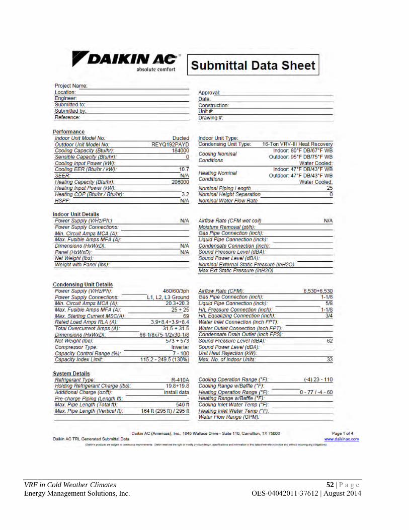
VRF in Cold Weather Climates 52 | P a g e Energy Management Solutions, Inc. OES-04042011-37612 | August 2014
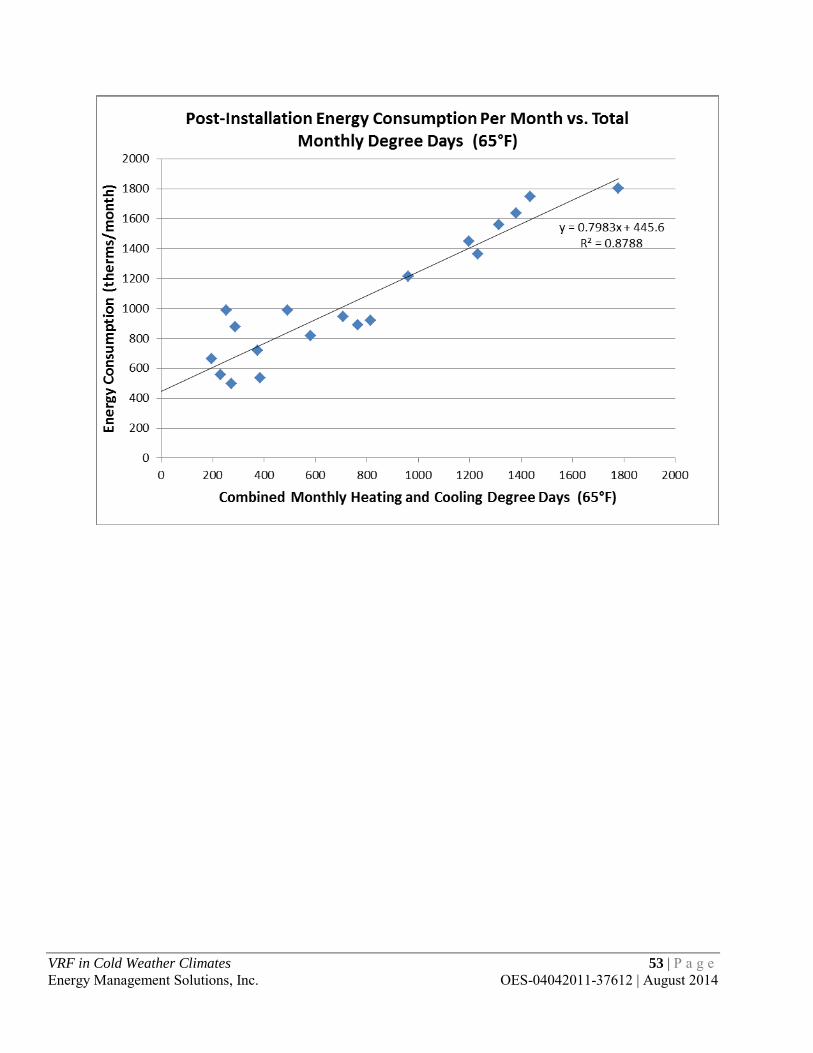
VRF in Cold Weather Climates 53 | P a g e Energy Management Solutions, Inc. OES-04042011-37612 | August 2014

Spreadsheet with detailed calculations for rebate and SPP estimations – Minnesota Power Cloquet Service Center
ENERGY COSTS: $/kWh = 0.05306 Yes 3.5$/kW = 5.86 Office 8.5
Free Cooling Hours: 572Current Cooling Heating New Cooling Heating
Existing Unit: Number of Units: 1 EFLH: 753 4,000 EFLH: 753 4,000Proposed Unit: Number of Units: 2
Cooling Type: Electric Cooling Type: ElectricMBTU/hr provided: 384.00 MBTU/hr provided: 184.00
EER = 8.5 Btuh/watt EER = 10.7 Btuh/watt
Heating Type: Electric Heating Type: ElectricMBTU/hr provided: 432.00 MBTU/hr provided: 206.00
COP = 1.00 COP = 2.30
DEMAND SAVINGS:Required kW for Cooling:
Current: 45.18 kW Current: 432.00 MBTU/hrNew: 34.39 kW New: 179.13 MBTU/hr
Demand Saved = Cooling: 10.78 kW Demand Saved = Heating: 35.62 kW
ENERGY SAVINGS: Cooling Savings = 8,120 kWh/YearEconomizer Savings = 19,673 kWh/YearHeating Savings = 142,482 kWh/Year
170,275 kWh/Year
COST SAVINGS: Cooling Cost Saved = $652.04 /YearEconomizer Cost Saved = $1,043.82 /YearHeating Cost Saved = $9,334.36 /YearTotal Saved = $11,030.22 /Year
OTHER SAVINGS: O&M Savings = $150
INCENTIVE: Cooling Incentive = $2,156.79 Demand Saved X $200
Economizer Incentive = $688.54 kWh Saved X $0.035
Heating Incentive = $7,124.10 Demand Saved X $200
Total Incentive = $9,969.43
INCREMENTAL COST: SIMPLE PAYBACK:Before Incentive = $106,000.00 Before Incentive = 9.6 Years incremental cost / total cost savings
After Incentive = $96,030.57 After Incentive = 8.7 Years (incremental cost - rebate) / AC cost savings
Variable Refrigerant FlowIMPROVEMENT MADE:
Is There a Current Unit: Months Cooled:What type of facility: Months Heated:
Disclaimer: All values are estimates based on information provided at the time. These values are not to be taken as fact and proof of installation is needed for rebates to be issued.
Prepared by:Email:
Phone Number:
Cole [email protected]
MN Dept. Commerce Deemed Savings EFLH for Cooling
MN Dept. Commerce Deemed Savings EFLH for Heating
Estimated Capacity of Current Equipment : New Equipment Capacity:
Required MBTU of Fuel for Heating:
VRF in Cold Weather Climates 54 | P a g e Energy Management Solutions, Inc. OES-04042011-37612 | August 2014

APPENDIX E: SUPPLEMENTARY INFORMATION FOR ST. OTTO’S CARE CENTER
VRF in Cold Weather Climates 55 | P a g e Energy Management Solutions, Inc. OES-04042011-37612 | August 2014
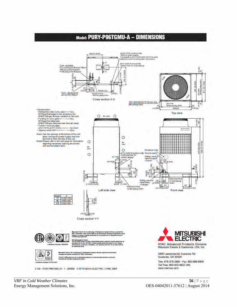
VRF in Cold Weather Climates 56 | P a g e Energy Management Solutions, Inc. OES-04042011-37612 | August 2014

VRF in Cold Weather Climates 57 | P a g e Energy Management Solutions, Inc. OES-04042011-37612 | August 2014

Spreadsheet with detailed calculations for rebate and SPP estimations – St. Otto’s Care Center
ENERGY COSTS: $/kWh = 0.0800573 Yes 3.5$/kW = 0 Health Care 8.5
Free Cooling Hours: 572Current Cooling Heating New Cooling Heating
Existing Unit: Number of Units: 86 EFLH: 1,246 3,636 EFLH: 1,246 3,636Proposed Unit: Number of Units: 6
Cooling Type: Electric Cooling Type: ElectricMBTU/hr provided: 10.57 MBTU/hr provided: 96.00
EER = 9.2 Btuh/watt EER = 12.8 Btuh/watt
Heating Type: Electric Heating Type: ElectricMBTU/hr provided: 6.82 MBTU/hr provided: 108.00
COP = 1.00 COP = 3.70
DEMAND SAVINGS:Required kW for Cooling:
Current: 98.81 kW Current: 586.52 MBTU/hrNew: 45.00 kW New: 175.14 MBTU/hr
Demand Saved = Cooling: 53.81 kW Demand Saved = Heating: 57.95 kW
ENERGY SAVINGS: Cooling Savings = 67,043 kWh/YearEconomizer Savings = 25,740 kWh/YearHeating Savings = 210,705 kWh/Year
303,488 kWh/Year
COST SAVINGS: Cooling Cost Saved = $5,367.28 /YearEconomizer Cost Saved = $2,060.68 /YearHeating Cost Saved = $16,868.51 /YearTotal Saved = $24,296.46 /Year
OTHER SAVINGS: O&M Savings = $2,000
INCENTIVE: Cooling Incentive = $10,761.30 Demand Saved X $200
Economizer Incentive = $900.90 kWh Saved X $0.035
Heating Incentive = $11,589.96 kWh Saved X $0.035
Total Incentive = $23,252.16
INCREMENTAL COST: SIMPLE PAYBACK:Before Incentive = $240,000.00 Before Incentive = 9.9 Years incremental cost / total cost savings
After Incentive = $216,747.84 After Incentive = 8.9 Years (incremental cost - rebate) / AC cost savingsDisclaimer: All values are estimates based on information provided at the time. These values are not to be taken as fact and proof of installation is needed for rebates to be issued.
Prepared by:Email:
Phone Number:
Cole [email protected]
MN Dept. Commerce Deemed Savings EFLH for Cooling
MN Dept. Commerce Deemed Savings EFLH for Heating
Estimated Capacity of Current Equipment : New Equipment Capacity:
Required MBTU of Fuel for Heating:
Variable Refrigerant FlowIMPROVEMENT MADE:
Is There a Current Unit: Months Cooled:What type of facility: Months Heated:
VRF in Cold Weather Climates 58 | P a g e Energy Management Solutions, Inc. OES-04042011-37612 | August 2014

APPENDIX F: SUPPLEMENTARY INFORMATION FOR THE MUNI: WAYZATA WINE AND SPIRITS
VRF in Cold Weather Climates 59 | P a g e Energy Management Solutions, Inc. OES-04042011-37612 | August 2014
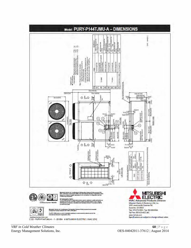
VRF in Cold Weather Climates 60 | P a g e Energy Management Solutions, Inc. OES-04042011-37612 | August 2014
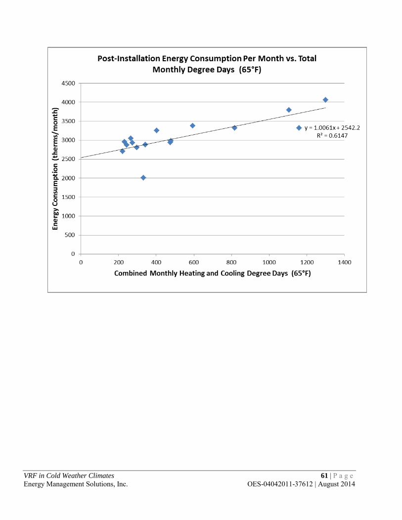
VRF in Cold Weather Climates 61 | P a g e Energy Management Solutions, Inc. OES-04042011-37612 | August 2014
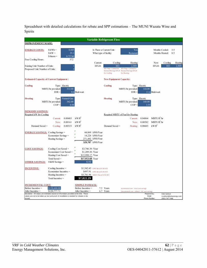
Spreadsheet with detailed calculations for rebate and SPP estimations – The MUNI Wazata Wine and Spirits
ENERGY COSTS: $/kWh = 0.085 Yes 3.5$/kW = 35.1 Resturant 8.5$/therm = 0.75740
Free Cooling Hours: 572Current Cooling Heating New Cooling Heating
Existing Unit: Number of Units: 1 EFLH: 883 2,909 EFLH: 883 2,909Proposed Unit: Number of Units: 2
Cooling Type: Electric Cooling Type: ElectricMBTU/hr provided: 312.00 MBTU/hr provided: 144.00
EER = 9.0 Btuh/watt EER = 11.6 Btuh/watt
Heating Type: Natural Gas Heating Type: ElectricMBTU/hr provided: 342.00 MBTU/hr provided: 160.00
COP = 0.98 COP = 3.55
DEMAND SAVINGS:Required kW for Cooling:
Current: 0.00483 kW/ft2 Current: 0.04864 MBTU/ft2/hrNew: 0.00161 kW/ft2 New: 0.00582 MBTU/ft2/hr
Demand Saved = Cooling: 0.00323 kW/ft2 Demand Saved = Heating: 0.00603 kW/ft2
ENERGY SAVINGS: Cooling Savings = 44,069 kWh/YearEconomizer Savings = 14,226 kWh/YearHeating Savings = 271,492 kWh/Year
329,787 kWh/Year
COST SAVINGS: Cooling Cost Saved = $3,746.30 /YearEconomizer Cost Saved = $1,209.20 /YearHeating Cost Saved = $12,998.17 /YearTotal Saved = $17,953.68 /Year
OTHER SAVINGS: O&M Savings = $150
INCENTIVE: Cooling Incentive = $1,542.43 kWh Saved X $0.035
Economizer Incentive = $497.91 kWh Saved X $0.035
Heating Incentive = $5,781.96 MBTU Saved X $0.003
Total Incentive = $7,822.29
INCREMENTAL COST: SIMPLE PAYBACK:Before Incentive = $128,600.00 Before Incentive = 7.2 Years incremental cost / total cost savings
After Incentive = $120,777.71 After Incentive = 6.7 Years (incremental cost - rebate) / AC cost savingsDisclaimer: All values are estimates based on information provided at the time. These values are not to be taken as fact and proof of installation is needed for rebates to be issued.
Prepared by:Email:
Phone Number:
Cole [email protected](952) 767-7468
MN Dept. Commerce Deemed Savings EFLH for Cooling
MN Dept. Commerce Deemed Savings EFLH for Heating
Estimated Capacity of Current Equipment : New Equipment Capacity:
Required MBTU of Fuel for Heating:
Variable Refrigerant FlowIMPROVEMENT MADE:
Is There a Current Unit: Months Cooled:What type of facility: Months Heated:
VRF in Cold Weather Climates 62 | P a g e Energy Management Solutions, Inc. OES-04042011-37612 | August 2014