variable refrigerant flow-heat recovery performance ... · variable refrigerant flow–heat...
TRANSCRIPT

Variable Refrigerant Flow-Heat Recovery Performance Characterization
Walt Hunt, Harshal Upadhye, and Ron Domitrovic, Electric Power Research Institute Paul Delany and Bach Tsan, Southern California Edison
Mira Vowles, Bonneville Power Administration ABSTRACT
Anecdotal suggestion and manufacturer provided data provides evidence that variable refrigerant flow systems with heat recovery (VRF-HR) provide a significant opportunity for building energy savings under certain conditions. Actual operational data showing the performance of heat recovery systems under varying conditions is scarce. This paper details the testing of a VRF-HR system under laboratory controlled conditions, revealing operational characteristics. A four-zone VRF-HR system was tested at specified conditions with varying degrees of connected combinations of cooling and heating demand.
Results show system power draw, delivered capacity, and EER are dynamic with changes in total connected load, ratio of cooling to heating, and system net operating mode (net cooling / net heating). The results of this work inform VRF designers, model developers and energy efficiency practitioners interested in pursuing VRF as an HVAC resource.
Introduction
Space conditioning accounts for the largest percentage of energy use in the residential and commercial buildings. A continuous effort is being made by regulators, utilities, manufacturers, and building owners to implement higher efficiency space conditioning technologies. Traditional space conditioning equipment in the U.S., both packaged and split systems, is single speed and uses ductwork to distribute supply air throughout the conditioned space. Two improved areas in advanced space conditioning systems include variable speed components and the separation of the conditioned space into zones.
One emerging space conditioning system is variable refrigerant flow (VRF) which is a multi-zone variable capacity heat pump. VRF systems consist of multiple indoor units which can operate independently of each other while being coupled to the same outdoor unit. Certain VRF systems can be configured with heat recovery technology which allows for simultaneous cooling and heating operation within the same system of indoor units. Variable refrigerant flow–heat recovery (VRF-HR) systems typically consist of multiple indoor units interconnected by a heat recovery unit which is tied to a single outdoor unit as shown in Figure 1.
3-138©2012 ACEEE Summer Study on Energy Efficiency in Buildings
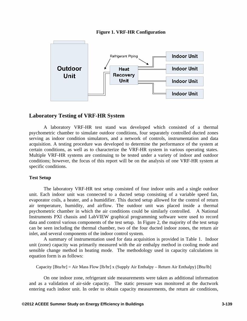
Figure 1. VRF-HR Configuration
Laboratory Testing of VRF-HR System A laboratory VRF-HR test stand was developed which consisted of a thermal
psychometric chamber to simulate outdoor conditions, four separately controlled ducted zones serving as indoor condition simulators, and a network of controls, instrumentation and data acquisition. A testing procedure was developed to determine the performance of the system at certain conditions, as well as to characterize the VRF-HR system in various operating states. Multiple VRF-HR systems are continuing to be tested under a variety of indoor and outdoor conditions; however, the focus of this report will be on the analysis of one VRF-HR system at specific conditions.
Test Setup
The laboratory VRF-HR test setup consisted of four indoor units and a single outdoor
unit. Each indoor unit was connected to a ducted setup consisting of a variable speed fan, evaporator coils, a heater, and a humidifier. This ducted setup allowed for the control of return air temperature, humidity, and airflow. The outdoor unit was placed inside a thermal psychometric chamber in which the air conditions could be similarly controlled. A National Instruments PXI chassis and LabVIEW graphical programming software were used to record data and control various components of the test setup. In Figure 2, the majority of the test setup can be seen including the thermal chamber, two of the four ducted indoor zones, the return air inlet, and several components of the indoor control system.
A summary of instrumentation used for data acquisition is provided in Table 1. Indoor unit (zone) capacity was primarily measured with the air enthalpy method in cooling mode and sensible change method in heating mode. The methodology used in capacity calculations in equation form is as follows:
Capacity [Btu/hr] = Air Mass Flow [lb/hr] x (Supply Air Enthalpy – Return Air Enthalpy) [Btu/lb]
On one indoor zone, refrigerant side measurements were taken as additional information
and as a validation of air-side capacity. The static pressure was monitored at the ductwork entering each indoor unit. In order to obtain capacity measurements, the return air conditions,
3-139©2012 ACEEE Summer Study on Energy Efficiency in Buildings

supply air conditions, and volumetric air flow were measured for each indoor unit. Outdoor air conditions of temperature and humidity were also measured and controlled in the environmental outdoor chamber. Power measurements were recorded for each indoor unit and the outdoor unit. With the values of capacity and power, thermal performance and efficiency of the system could be tabulated for various operations and conditions. Refrigerant side measurements of temperature and pressure were taken at the inlet and outlet of all indoor and outdoor units. Refrigerant mass flow was measured on one of the four indoor units which when used with refrigerant temperature and pressure readings allowed for a comparison of refrigerant-side capacity to air-side capacity. Internal VRF-HR system values such as compressor speed, fan speed of the indoor and outdoor units, and expansion valve positions were not directly recorded by the data acquisition system; however, these values were monitored with manufacturer supplied software in order to understand and characterize the system.
Figure 2. Laboratory Test Setup
Note: Only two of the four indoor zones are shown in the figure.
Table 1. Instrumentation used for Data Acquisition Measurement H/W P/N Accuracy
Indoor Unit Airflow Veltron DPT2500 Plus ±0.5%
Return/Supply/Outdoor Air Temperature and Humidity
Vaisala HMD60Y ±1% RH; ±0.2°C
Indoor Unit Power Shark
Shark 100T ±0.2%
Outdoor Unit Power Shark 200T
Refrigerant Line Pressure Serta 205-2 ±0.65 psi
Refrigerant Line Temperature Omega TT-T-24S ±0.5°C
Refrigerant Mass Flow Micro Motion CMF025 ±0.05%
3-140©2012 ACEEE Summer Study on Energy Efficiency in Buildings
Test Procedure The testing procedure was developed to determine the performance of a VRF-HR system
under certain operations and to gain a better understanding of variable refrigerant flow with heat recovery technology. The testing procedure was not meant to simulate any specific rating conditions; however, the ANSI/AHRI Standard 1230 for rating variable refrigerant systems was used to provide guidance regarding relevant testing conditions and methodology. The laboratory testing procedure consisted of varying the number of indoor units in operation and the ratio of cooling to heating zones at specified indoor and outdoor conditions. The VRF-HR system was tested in both cooling and heating operation, as well as in simultaneous heating and cooling operation. A test condition was determined to be accurate and steady if the relevant parameters had remained within their determined tolerances for a period of ten minutes. The relevant variables for steady state included all of the controlled parameters by the test stand, as well as the power consumption and supply air conditions for the VRF-HR system.
Specific testing conditions were determined based on relevance and the ability of the test stand to achieve the desired conditions. In cooling mode operation, return air temperature, return air humidity, and outdoor temperature were specified. In heating operation, the return air temperature, outdoor temperature, and outdoor humidity were specified. For cooling mode, the return air was set at 80°F dry bulb/67°F wet bulb, and the outdoor temperature was maintained at 95°F. For heating mode, the indoor dry bulb temperature was set at 70°F, and the outdoor temperature was maintained at 47°F dry bulb/43°F wet bulb. For simultaneous heating and cooling, return air was maintained at 80°F dry bulb/67°F wet bulb for units in cooling and 70°F for units in heating with an outdoor temperature of 65°F. Variables such as compressor speed and fan speed of the VRF-HR system were not specified or controlled, to allow the system to function as it would in a real application. The internal system logic controlled compressors, fans, and expansion valves as designed by the manufacturer.
Characteristics of VRF-HR System
Variable refrigerant flow systems with heat recovery capability operate differently than traditional single or multi-stage split systems. Understanding the characteristics of a VRF-HR system is critical in order to implement the system effectively into buildings and accurately model the performance of a system. The VRF-HR system which is analyzed in this report was a 6 ton system with four 2 ton indoor units. The connected indoor capacity thus exceeded the nominal outdoor unit capacity by 2 tons. The ratio of indoor to outdoor capacity is referred to as the “combination ratio” and manufacturers allow combination ratios that exceed 1.0. Percent Indoor Unit Operation
One of the distinctions of a variable refrigerant flow system is the ability for each indoor
unit to operate independently of the other units. Each indoor zone can be conditioned with the needed thermal load for that space, as opposed to traditional space conditioning equipment which can overcool or overheat particular zones in a given space. In a VRF system when the set point temperature in a specific zone is met, the indoor unit for that zone will cease operation. A key characteristic to understand in a VRF-HR system is the performance of the system when different percentages of indoor units are in operation.
3-141©2012 ACEEE Summer Study on Energy Efficiency in Buildings

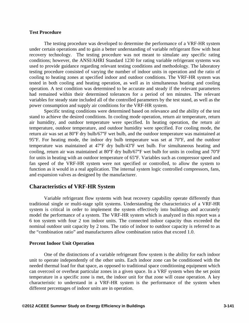
As previously mentioned, the VRF-HR test stand consisted of four indoor units. The system was tested with 25%, 50%, 75%, and 100% of the indoor units in operation. Both cooling and heating tests were performed for specified indoor and outdoor air conditions at each level of indoor unit operation. Figure 3 shows how heating capacity varies at a particular testing condition as a function of the number of indoor units in operation. The figure shows the total heating capacity for the system and the average amount of heating capacity per indoor unit. As the number of indoor units in operation increases from one to two, the average capacity per unit remains relatively constant since the outdoor unit’s available capacity has not yet been met or exceeded; however, as the number of units in operation increases to three and four, the average capacity per unit decreases as outdoor unit capacity approaches its maximum.
Figure 4 shows the power consumption and efficiency for the same test case shown in Figure 3. Notice in Figure 4 as the indoor unit operation goes from one to two units operating; power consumption increases in the system. This power increase was due to the increase in compressor speed to accommodate the now two units calling for a heating load. As the number of units in operation increases to three and four, the compressor reaches its maximum speed which can be seen in Figure 4 by the relatively steady power consumed after two units in operation. When the compressor reaches its maximum speed, the system is unable to provide the full amount of heating capacity to each indoor unit. Also notice in Figure 4 that the efficiency represented as the coefficient of performance (COP) increases as the percent of indoor units in operation increases. The VRF-HR system is operating most efficiently when more units are operating simultaneously. This may also be in part a consequence of advantageous relative heat exchanger size of the indoor units, since each is sized as 2 ton, but operating at reduced capacity when all zones are calling for heat.
Similarly in Figure 5 and 6, capacity and efficiency in cooling mode are shown as a function of percent indoor unit operation for a specified condition. Cooling efficiency is presented by an energy efficiency ratio (EER) in Figure 6. Similar trends can be seen in cooling mode, as were seen in heating mode. In cooling mode, the system does appear to be more affected by an increase in the number of indoor units in operation as the average capacity when four units are operating is nearly half of the capacity compared to when only one of the units is in operation. Trends in average capacity, efficiency, and power consumption in cooling mode are all similar to those previously discussed in heating mode.
3-142©2012 ACEEE Summer Study on Energy Efficiency in Buildings
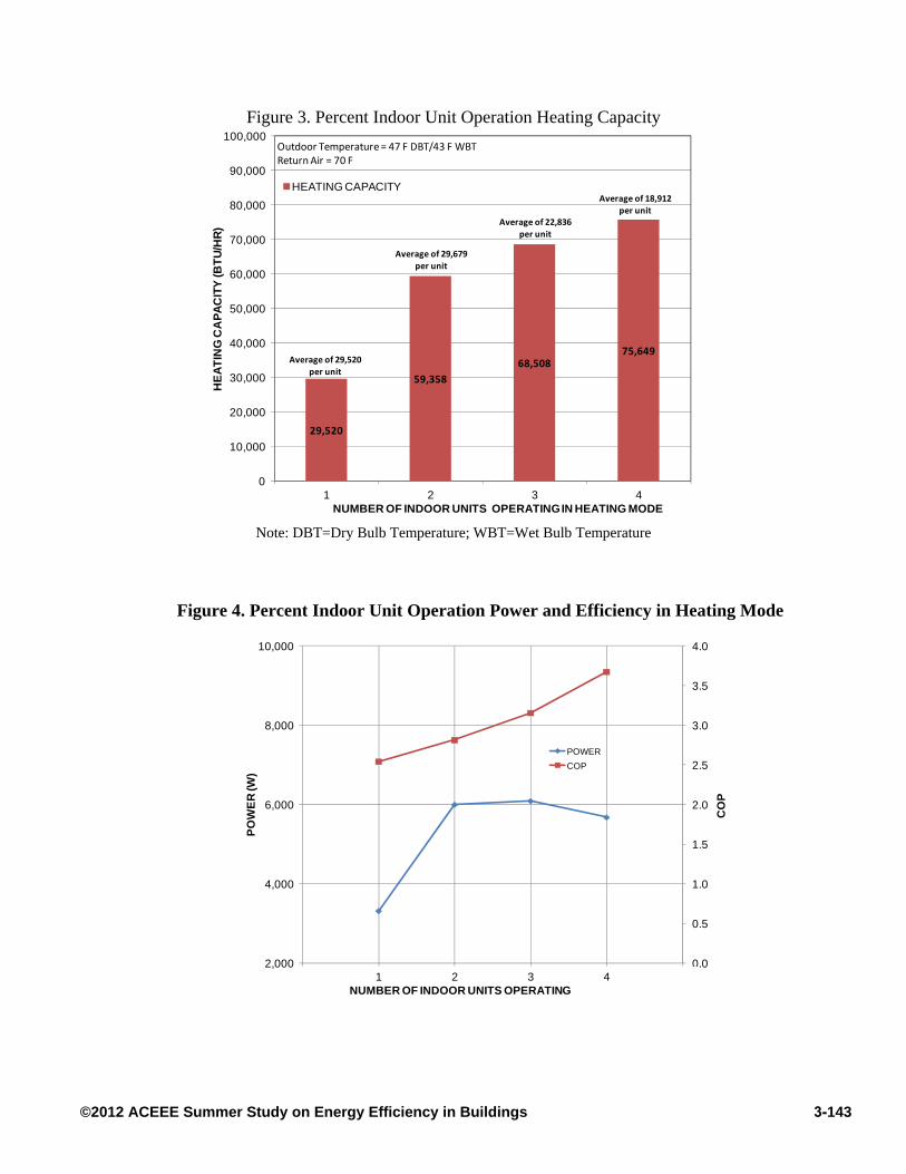
Figure 3. Percent Indoor Unit Operation Heating Capacity
Note: DBT=Dry Bulb Temperature; WBT=Wet Bulb Temperature
Figure 4. Percent Indoor Unit Operation Power and Efficiency in Heating Mode
29,520
59,358
68,50875,649
0
10,000
20,000
30,000
40,000
50,000
60,000
70,000
80,000
90,000
100,000
1 2 3 4
HE
AT
ING
CA
PA
CIT
Y (
BT
U/H
R)
NUMBER OF INDOOR UNITS OPERATING IN HEATING MODE
HEATING CAPACITY
Outdoor Temperature = 47 F DBT/43 F WBTReturn Air = 70 F
Average of 29,520 per unit
Average of 29,679 per unit
Average of 22,836 per unit
Average of 18,912 per unit
0.0
0.5
1.0
1.5
2.0
2.5
3.0
3.5
4.0
2,000
4,000
6,000
8,000
10,000
0 1 2 3 4 5
CO
P
PO
WE
R (W
)
NUMBER OF INDOOR UNITS OPERATING
POWER
COP
3-143©2012 ACEEE Summer Study on Energy Efficiency in Buildings
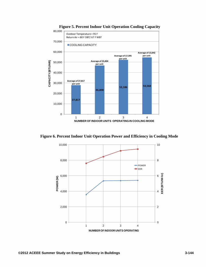
Figure 5. Percent Indoor Unit Operation Cooling Capacity
Figure 6. Percent Indoor Unit Operation Power and Efficiency in Cooling Mode
27,817
46,80852,186 54,568
0
10,000
20,000
30,000
40,000
50,000
60,000
70,000
80,000
1 2 3 4
CA
PA
CIT
Y (B
TU
/HR
)
NUMBER OF INDOOR UNITS OPERATING IN COOLING MODE
COOLING CAPACITY
Outdoor Temperature= 95 FReturn Air = 80 F DBT/ 67 F WBT
Average of 27,817
per unit
Average of 23,404
per unit
Average of 17,395
per unit
Average of 13,642
per unit
0
2
4
6
8
10
0
2,000
4,000
6,000
8,000
10,000
0 1 2 3 4 5
EE
R (B
TU
/W-h
r)
PO
WE
R (W
)
NUMBER OF INDOOR UNITS OPERATING
POWER
EER
3-144©2012 ACEEE Summer Study on Energy Efficiency in Buildings
Simultaneous Cooling and Heating Performance Heat recovery systems have the ability to transfer waste heat to a space requiring heating,
thus saving energy. In many real world applications, there exists a need for constant heating or cooling in a particular space regardless of the outdoor conditions. An example would be a server room where the space needs to be continually cooled to maintain normal operating temperatures. A VRF-HR system has the capability to transfer heat from one indoor zone to another. For instance if one indoor zone was calling for heating while another was calling for cooling, heat could be transferred by the indoor units in cooling to those in heating. The outdoor unit would operate accordingly based on the conditions and need called for by the indoor units. If the majority of the indoor units are calling for cooling, then the outdoor unit would act as a condenser and the overall system is in net cooling mode. Conversely, if the majority call is for heat, the outdoor unit will operate as an evaporator and the system is in net heating mode.
The ability to transfer heat between the indoor units is an integral design attribute of a VRF-HR system, and each manufacturer has unique and proprietary methods for accomplishing heat recovery. All systems have some version of a heat recovery/switching box located between the indoor and outdoor units that is an integral part of the heat recovery process. At the heat recovery box, refrigerant is received and distributed to and from the indoor and outdoor units.
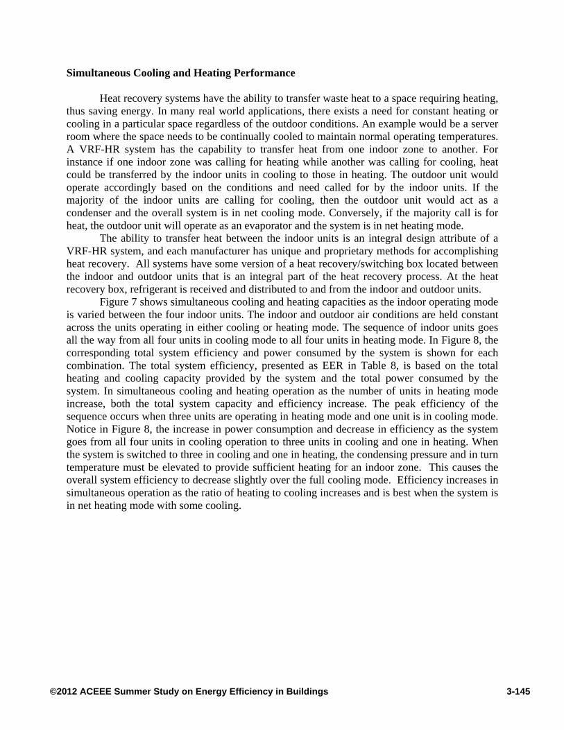
Figure 7 shows simultaneous cooling and heating capacities as the indoor operating mode is varied between the four indoor units. The indoor and outdoor air conditions are held constant across the units operating in either cooling or heating mode. The sequence of indoor units goes all the way from all four units in cooling mode to all four units in heating mode. In Figure 8, the corresponding total system efficiency and power consumed by the system is shown for each combination. The total system efficiency, presented as EER in Table 8, is based on the total heating and cooling capacity provided by the system and the total power consumed by the system. In simultaneous cooling and heating operation as the number of units in heating mode increase, both the total system capacity and efficiency increase. The peak efficiency of the sequence occurs when three units are operating in heating mode and one unit is in cooling mode. Notice in Figure 8, the increase in power consumption and decrease in efficiency as the system goes from all four units in cooling operation to three units in cooling and one in heating. When the system is switched to three in cooling and one in heating, the condensing pressure and in turn temperature must be elevated to provide sufficient heating for an indoor zone. This causes the overall system efficiency to decrease slightly over the full cooling mode. Efficiency increases in simultaneous operation as the ratio of heating to cooling increases and is best when the system is in net heating mode with some cooling.
3-145©2012 ACEEE Summer Study on Energy Efficiency in Buildings
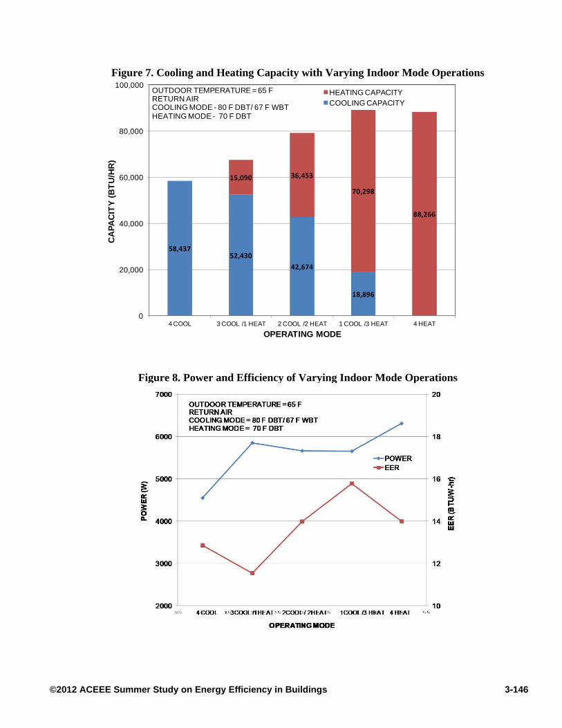
Figure 7. Cooling and Heating Capacity with Varying Indoor Mode Operations
Figure 8. Power and Efficiency of Varying Indoor Mode Operations
58,43752,430
42,674
18,896
15,090 36,453
70,298
88,266
0
20,000
40,000
60,000
80,000
100,000
4 COOL 3 COOL /1 HEAT 2 COOL /2 HEAT 1 COOL /3 HEAT 4 HEAT
CA
PA
CIT
Y (
BT
U/H
R)
OPERATING MODE
HEATING CAPACITYCOOLING CAPACITY
OUTDOOR TEMPERATURE = 65 FRETURN AIRCOOLING MODE - 80 F DBT/ 67 F WBTHEATING MODE - 70 F DBT
3-146©2012 ACEEE Summer Study on Energy Efficiency in Buildings
Conclusion Laboratory test data from a commercially available VRF-HR unit is presented along with
the trends in capacity, power draw, and efficiency. The effect on system performance with changing percent indoor unit operation and simultaneous heating and cooling ratio of such a unit is discussed in detail. Heat recovery mode, which until now has not been studied in detail, has been investigated with data presented. The performance in heat recovery mode is a function of the system architecture and reaches highest efficiency in net heating mode with fractional cooling demand. This work is continuing on a path toward providing indicative performance maps for several VRF systems that can be used to provide input for VRF system models in building energy software products.
References ANSI/AHRI Standard 1230 ‘2010 Standard for Performance Rating of Variable Refrigerant
Flow (VRF) Multi-Split Air-conditioning and Heat Pump Equipment’ Air-Conditioning, Heating, and Refrigeration Institute, Arlington, VA.
ASHRAE Handbook 2009, Fundamentals, American Society of Heating, Refrigerating and Air-
Conditioning Engineers, Inc., Atlanta GA. Amarnath, A. and Blatt, M. 2008, Variable Refrigerant Flow: An Emerging Air Conditioner and
Heat Pump Technology, ACEEE Summer Study on Energy Efficiency in Buildings Xia,J., Winanday E., Georges, B. and Lebrun, J. 2002, Testing Methodology for VRF Systems,
The International Refrigeration and Air Conditioning Conference, Purdue University, USA.
Wang, X., Xia, J., Zhang,X., Shiochi,S., Peng, C. and Jiang, Y. 2009, Modeling and
Experimental Analysis of Variable Refrigerant Flow Air-Conditioning Systems, 11th International IBPSA Conference, Glasgow, Scotland.
Liu, X. and Hong, T. 2010, Comparison of Energy Efficiency between Variable Refrigerant
Flow Systems and Ground Source Heat Pump Systems, Energy and Buildings 42 (2010).
3-147©2012 ACEEE Summer Study on Energy Efficiency in Buildings