peformance of brick masonry veneers · 2015-07-22 · of brick masonry veneer using shelf angle...
TRANSCRIPT
PEFORMANCE OF BRICK MASONRY VENEERS
by
A.A. Hamid Associ ate Professor, Department of Civil Engineering
Drexel University, Philadlephia, Pennsylvania, USA
I.J. Becica Vice President, Oliver & Becica, A.I.A., P.A.
Cherry Hill, New Jersey,USA
H.G. Harris Professor , Department of Civil Engineering
Drexel University, Philadelphia , Pennsylvania, USA
ABSTRACT
Recently, there have been many failures of brick masonry veneers. Modes of failures var y from minor cracking to complete collapse of sections of cladding. The result is violation of the building envelope and a potential safety hazard to pedestrians. Failures of brick veneers are mainly attributed to the deformational incompatibility of the veneer and the structural frame. Engineers and Architects should account for the differential movements in their design and accomodate the movements by proper detailing. This paper discusses the factors which contribute to differential movements and presents two case studies of failures of brick masonry veneer using shelf angle details. Recommendations of design and construction practices which lead to safe and serviceable brick veneers are presented.
1. INTRODUCT ION
Ma sonry veneers are simple minded structures. They express some architectural identity for the satisfaction of Owners, their creators, Planning Board Officers, and perhaps historic Commissions. Further personifications may include their elegance and beauty, but their fundamental purpose is to envelope the space we call buildings, an envelope which must function as a safe, weather-tight membrane.
Facade complexities begin to flourish when designers begin detailing and masons construct the connection between slender panels of masonry and supporting structural frames. The majority of post-failure analysis performed on visually distressed facades, shows that assumptions were made regarding facade-structure interaction which were inconsistent with nature's interpretation of her own basic laws. That is, the redundancy built into brick panel facades was ignored and development of in-plane forces not normally present in determinate systems were not recognized.
321
The redundant facade system is known to distress when environmental exposure to temperature differentials and moisture accumulation force confined expansion. Confinement is offered by the various connection details which form the link to the building frame. The same connections provide for coupling of frame deformations which are superimposed according to equilibrium and compatibility relationships. Therein lies the facade-structure interaction.
This paper reviews the components of facade structural behavior, construction details, and analysis techniques employed by the authors to explain two particular brick masonry facade distress problems. The ultimate goal of the studies reported here is to recommend repair schemes economically suitable to each situation.
2. FACADE DISTRESS - CONTRIBUTING FACTORS
This discussion on factors contributing to distress in brick masonry facades will be limited to brick masonry panels on shelf angles connected to concrete frames or concrete flat plate structures. Case studies, as reported later, are limited to this type of construction. The majority of brick masonry veneer distress is due to deformation incompatibility with the supporting structure. Factors contributing to the deformations of concrete frames and brick masonry veneers are discussed in the following sections.
2.1 Deformations of Concrete Frames
Axial shortening of concrete frames is manifested in elastic shrinkage, and creep deformations. Thermal strains are not discussed and are neglected for columns within the building envelope. It is to be noted that partially exposed columns may be vulnerable to strain gradient effects and degradation due to partial exposure.
Elastic deformations include axial shortening of columns and bending deformations of spandrel beams or edge beams in flat plate construction. These deformations are primarily functions of stress leveI and material properties.
Shrinkage and creep deformation in concrete structures is well documented (4). In summary, the analysis of creep and shrinkage recognizes a complex interaction of parameters which affect concrete time dependent behavior. These parameters include the ratio of tension and compression reinforcement, concrete curing techniques, changes in environmental conditions such as humidity and temperature, concrete water/cement ratio, concrete aggregate/ cement ratio, reinforcement steel placement tolerance, crack distribtuion, magnitude of applied stress, member volume to surface area relationships, and load history. In the case of a retro-analysis, many of these parameters may not be fully established. Engineering judgment and experience are used in conjunction with observations made during site investigations and review of construction documents as provided by building Owners.
322

Estima t es of concrete frame creep and shrinkage deformations range from two and one-half times the elastic deformations for the f o rmer and .02 - .05% for the latter (4, 10). Overall frame s h o r t ening which includes alI of the above effects can range from .0 1 - .09% (2 ) .
Bri c k masonry panels are known to expand and contract both in the vertical and horizontal directions. There exists sufficient guidance in building codes for the location of vertical expansion / contraction join t s. The purpose of these joints is to permit wall movement in the horizontal direction. A thorough review of each building design should commence and culminate in properly detailed joints. Wall panels of interest here are vertically spanning, slender brick masonry panels and therefore their vertical expansion will be discussed in what follows.
Elastic deforma t ions in brickwork panels can be readily neglected simply beca use these panels are not designed as load bearing members and consequently are called on to support only their own weight. Analysis of elastic deformations follows Hooks Law using elastic modulus values according to building code recommendations. Typically, 1000f'm is recommended (f'm is the compressive strength of brick masonry as measured from prism t esting). However, in the authors' experience, more accurate values range from 400 to 700 f'm. Lenczner (7) has suggested an equation which relates the square root of brick strength to the elastic modulus of masonry. He reports a correlation coefficient of 0 .96 for an equation based on linear regression analysis of a variety of wall data.
Shrinkage deformations are not characteristic of clay masonry (8). Shrinkage is associated with cementitious materiaIs and mortar j o ints in brick masonry walls represent the only material subject to this type of deformation. Since the mortar joint only represe n ts a small portion of the total wall area, shrinkage can be readily neglected. Such is not the case in concrete masonry. Shrinkage is more significant and sensitive to curing technique, exposure, method of installation, moisture content, relative humidity, aggregate type, and morta r joint construction (7).
Creep deformations are highly sensitive to stress leveIs (6). It is believed (5) that creep is manifested in a moisture transfer and subsequent collapse of the cement gel structure within mortar joints. Therefore, since stress leveIs in the facades are normally quite low as in the case of elastic deformations and since mortar joints only represent a small portion of the total wall area, creep deformation can usually be neglected.
In the case of significant axial loads on brick masonry veneers, creep strains can range from 0.4 to 1.4 times the elastic component (10). This represents approximately 20-25% of the creep which can be expected to occur in concrete structures (2). This factor becomes significant when relative creep deformations are examined between frame and facade panels.
323
One significant environmental condition affecting masonry veneers is temperature. The most criticaI parameter affecting the magnitude of thermal forces induced in masonry panels is the difference between panel temperature at construction time and the peak post construction temperature. Monk (8) discusses the dif ference between diurnal and seasonal temperature differences. The former may induce strain gradients and therefore cause a curling or bowing of walls where the latter may induce high axial forces. It has been estimated that seasonal temperature differences can vary from as high as 50°C. for walls built in winter to -50°C. for walls built in summer (2). Other factors affecting thermal response can include wall azimuth, material properties and coloro An elaborate method for calculating thermal strains has been proposed by Grimm (3) and incorporates shading, reflectance and conductivity as well as alI of the above. Without knowledge of such details however, use of an average coefficient of thermal expansion and assumed maximum mean temperature difference could yield horizontal unrestrained thermal expansions of 0.045% and vertical expansion of 0.066% (1, 2).
Typical average thermal coefficients for brick masonry can be 3.6 x 10- 5 mm per degree celsius and as high as 10.6 x 10- 5 mm per degree celsius. Generally, thermal deformations are completely reversible if temperatures are cycled (8).
The final parameter which has been shown to significantly affect brickwork expansion is moisture. It has been shown (8) that moisture expansion is highly dependent on the amount of expansion clay units experience after kiln firing and prior to being installed in the wall. Moisture expansion is probably due to the chemical absorption of water and is typically irreversible. Jessop (5) reports moisture expansion coefficients ranging from .003-.133%. Monk (8) and Grimm (2) recommend a value of .02%.
The major factors which affect moisture expansion are time of exposure, time of laying, temperature of moisture, temperature of firing, relative humidity, cyclic wetting and drying, mortar joints, clay composition, and manufacturing process (5). Mortars containing dolemetic lime may have long term expansion due to delayed hydration (1) which is not present in pressure hydrated lime. Other mortar additives may also contribute to expansion in brick panels and designers are cautioned to question chemical stability of these materiaIs.
3. CONSTRUCTION DETAILS
Apart from the material properties discussed above, construction practice influences the behavior of masonry veneers. A typical brick masonry veneer detail for supporting panels from concrete structures is shown in Fig. 1. It should be noted that Fig. 1 is considered a proper detail in that vertical expansion of brick panels is provided for by a compressible joint located at the supporting angle. AIso, sufficient adjustment is provided by the anchorage system such that masonry coursing can be main tained during construction. The introduction of a flashing membrane and weep holes at the base of each wall segment
324

provides for drainage of occasional moisture which finds its way through imperfect masonry panels.
Various deviations from the typical detail shown in Figure 1 have led to serious veneer distress. As a typical example, the compressible joint is either not detailed properly or not installed properly. The result is significant vertical loads being superimposed upon the veneer system. A continuous mortar joint at this location provides, in most cases, the necessary redundancy to allow the expansive strains, as outlined previously, to develop. Secondly, failure of the drainage system con
.:. ". 0,) ') ~p
:-_ ..... H ... ... ~ é.:;.c;" \!!. _,;: _ .:;; ..... - F II..I.. EIOIi
. I
-,.z\,lU_'!i ' I.I~_
r-e~~ ... t;J..",'f"',{
:;::>ov e T A IL .... - ç L..OT
-- - M t=.íAL -"'\~ L Ii T
. ~~
lY'iA ...... FO"~_ P , -- Ma T A L F L A.c;w II..,J G
FULL ~~rú ... T --- - q l,)~~O~T .c; Ioo4 IM<"
" DO l fi. T.6.. \L At..JC;..OP"!
- " LO.,-
DO -l E "'\""':"1.. A,t..l C r<?'I"i .U UO .... -A~ .. o 0..".;1
Fig. Proper Shelf Angle Detail
sisting of flashing and thru-wall weep holes, can cause water to be entrapped between the rigid concrete structure and flexible masonry veneer. If freezing should occur, sufficient lateral pressures can be exerted on the masonry veneer to cause displacement laterally and potential collapse of wall panels.
Other construction conditions which cause potential distress are lack of lateral ties, accumulation of mortar droppings on flashings which prohibit drainage, improper alignment of supporting relieving angles and insufficient size of air space (less than 25mm) between veneer and the backup structure.
4. CASE STUDIES
The following case studies deal with relieving angle (shelf angles) supported masonry veneers on concrete frame structures. It will be shown that the two structures in question are similar in construction yet the method of analysis used in each case varies slightly. The problem presented here is an analysis that was required to show the cause of panel failure where the mode of failure was different.
The building in question is a 6 story apartment structure consisting of flat plate and column construction. A typical column tributary area is 13 square meters. The exterior facade consists of a light colored brick protruding 102 mm from a darker colored recessed brick panel which alternates around the perimeter of the building. A vertical caulk joint seals the offset panels. Only the continuous vertical panel which spans from foundation to roof elevation uninterrupted by window openings showed any signs of distress. A typical wall section is shown in Fig. 2.
325

Distress in the structure consisted of bowing of the masonry veneer at the shelf angle locations and spalling of the first two courses either above and/or below the bearing location of the shelf angle. Ninety percent of the spalling failures noted and 100 percent of the bowing failures occurred on the southeast elevation of the building. In the northern hemisphere this fact coincides with the greatest wall panel temperature gain. Because of the apparent sporadic nature of the veneer failures, a detailed analysis was called for to determine the cause of distress.
The first phase of the analysis was to establish certain as-built conditions and masonry phy-sical properties for input to numerical analysis. The construction sequence and details were
,-~ u
< W , >-a
;i ~
" ~
Fig.
~
) J
€ } ~
Il
~ f-~ Cc
,.l,. J111 IiÇ
.,. . -~ ~I .. "' ·
>rr11/ '-L...'ll'--- _ ~._ I1!.yl\ .. ...;6 "u_ J _e
144==*,~- 'l""Al"'l a l t...,; ú
4 ' CGH • ..IC e .. .... ·
- _ 'WAU- - eç
COL..- co"-c (!,~""':)e ae. .... v
2 Typical Wall Section
studied using documents provided by the building Owner. It became necessary to sample the brickwork in question to determine accurately masonry properties and to verify as-built conditions. A typical wall sample was selected and a diamond saw used to cut masonry prisms and individual brick specimens. Findings of the wall investigation indicated poor workmanship. The minimal number of weep holes were found and the cavity between backup masonry and veneer was not kept clean of mortar, therefore rendering the secondary drainage system consisting of flashing and weep holes inoperative. The caulk joint used to seal the offset brick panels was found to be severely cracked due to either non maintenance or improper installation. The shelf angle was bolted rigidly to the spandrel slab with only a slotted hole used for adjustment. Brickwork was found to be bearing on both the underside and topside of the relieving angle. An insufficient number of masonry wall ties were located. Wall ties consisted of 5mm diameter crimped "Z" type galvanized wire ties in combination with dovetail corrugated metal ties at reinforced concrete column locations. Of the wall ties located, forty percent were yielded in the vicinity of the shelf angle. In the test panel selected, a lateral deflection of approximately 50mm was indicated as shown in Fig. 3.
Prism specimens and brick specimens were tested in the laboratory. Brick strength was high at 90.5 N/mm 2 • Prism strength was 24.8 N/mm 2 and prism elastic modulus was found to be 11.7 x 10³ N/mm 2 • Note that the elastic modulus represents 478f'm. The average saturation coefficient as determined per ASTM C-67 was 0.89.
The total deformation due to creep, shrinkage and elastic shortening of the concrete frame was found to be 13.6mm over the
326

full height of the column behind the test pa nel . The analysis of creep and therrna l deforrnations in the brickwork panel indicated a net extension of 3.2rnm for the entire height of the brick panel. The combined effects of concrete frame shortening and brickwork expansion produced a compressive strain of 0.0012% or a stress of 14.1 N/rnm 2 . This stress represents 58% of the ultimate masonry compressive strength which far exceeds the allowable stress, but in itself does not constitute sufficient force to cause spalling.
A closer examination of the construction detail at the shelf angle is shown in Fig. 4. The 13mm mortar joint indicated at the front of the relieving angle represents a point of support for the brickwork panel above. The applied load on this mortar joint is one-half the
Fig. 3 Lateral Displacement at Shelf Angle
total load of the brickwork which is approximately 52 N/rnrn 2 . This represents a stress of 2.1 times the ultimate masonry strength and is sufficient to cause local spalling.
Assuming the mason contractor laid up brick to the underside of the relieving angle, and because there was no adjustment provided in the relieving angle installation, a gap between the last course beneath the angle and the angle must have existed. Under the influence of the forces described above, this gap would close causing uplift forces to be exerted on the story height above the relieving angle. Under this loading condition, which is essentially an eccentric load occurring well outside the kern of the panel, a net rotation at the relieving angle in the clockwise direction is produced. It is believed that this
,." ,," : .. u U .
q'Z Mt..A
10'2 " 1L;"2 ... e, ' ·HA ~
:1 ., Q j
<; ~ É l_ "" AUC. ~ E 11' I
r I~ ~,~ .. ~c ,;o" 50.- ~ - j
:>:
" r-Ir
/ /' -T -
:>: y
D / !
Fig.
/ /
UO""TA~ JOlkJl I>;E,UlO,U<;' (f? COPlUEf'IÇ
(GAP " '-ID Al-Júd' <;HOW\..; )
4 As-Built Shelf Angle Detail
rotation occurred prior to brickwork spalling and is the cause of the lateral displacement.
Another mechanisrn which has a potential input to the lateral displacement is the effect of entrapped water behind the panel freezing and forcing the panel outwards. The drainage system
327

behind the panel was found to be inoperative. The poor q uality of bed and head joints, as well as many instances of failed caulked joints where brick panels meet adjacent brick panels, would allow water to freely enter the cavity.
The remedial action called for removing 15 courses of brick in the vicinity of the shelf angle at distress locations and reinstalling new brick with the proper expansion joint detail. Addition of expansive wall ties was specified with new flashings and weepholes. The entire building was then waterproofed and recaulked to minimize water penetration.
Case Study No. 2 is a five story reinforced concrete flat slab structure. The exterior veneer is a composite block-brick masonry with a solid collar joint (Fig. 5). Despite the fact that the wall is solid, shelf angles, flashing and weep holes
couc. l!'>eAM
102 UV! ME.T Ç'1\.JD TO UUDE.~IDe: OF "'il.A.
were provided (Fig. 5). The design requires that a plastic flashing material extend from the base of the back up block (top of floor slab) down to the shelf
4iHCi.~~ A.UclL... -- : .
a n g 1 e • T h i s i s a d i s ta n c e o f w .... · " 0 I.. .... ______ w~a=====r-----l approximately one meter. In order to protect the integrity of the flashing, the designers indicate that no metal ties be located in this area. The result is a
BACje:, UP MAÇOU~
L one meter high section of wall which is not connected in any fashion to the back up
Fig. 5 Typical Wall Section
material. This results in a section of wall vulnerable to horizontal displacement due to water behind the wall.
which is extremely freezing of the
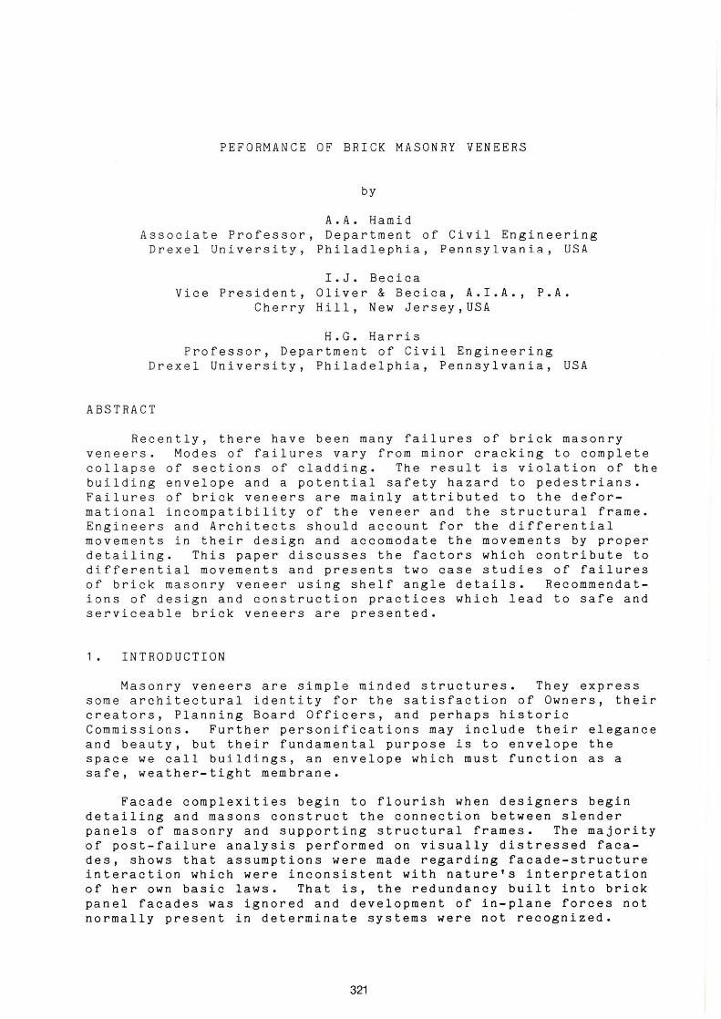
It was observed in the east wall of the south building that the bricks immediately above the shelf angle had spalled (Fig. 6) indicating high compressive stresses in the brick. The exterior wall construction is such that the water penetration normally associated with masonry is not handled properly. Adequate building envelope insulation was not provided which resulted in a dew point location with the wall. The problem manifested itself as large brick panels sliding off of their supporting angles with the potential of falling from the building. Structural steel channels were attached to the exterior wall for temporary support (see Fig. 6).
Masonry prisms were cut from the building veneer to determine properties required for the calculation of long term deformations of masonry. The prism test results revealed a low compressive strength of 13.7 N/mm 2 and a modulus of elasticity of 5520 N/mm 2 • The unit compressive strength was 36.2 N/mm 2 • A high saturation coefficient of 0.83 was obtained for the brick. This value exceeds the ASTM C-62 maximum saturation coefficient (0.78) for SW brick.
328
The analysis indicated that the cause of the problem is one of designo The design requires construction of a composite wall as opposed t o a cavity wall. A composite wall has the space behind the brick and in front of the back- up block filled solidly with mortar. A cavity wall leaves a clean space between the back of the brick and the front of the block as in Case Study #1. A cavity wall permits water which penetrates the brick wall to fali freely through the cavity and collect at the shelf angle. The shelf angles are protected with non-corrosive flashing and the flashing directs the water to weep holes which permit the water to drain from the cavity. A composite wall assumes that water will
Fig. 6 Spalling of Brick Veneer
not penetrate the brickwork. This often is an unreasonable assump tio n because wind driven rain can penetrate the wall through the mortar joints as well as the porous brick. The result of the utilization of the composite wall details is that the collar joint material becomes saturated and in winter freezes, forcing the brick to separate from the back-up block.
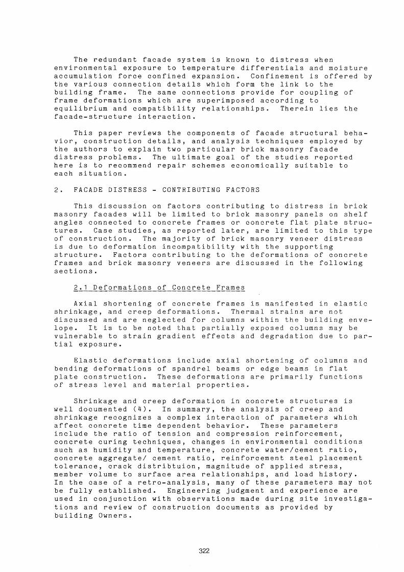
The designer did not detail nor specif y a expansion material directly beneath each sh e lf
compressi b le angle (F i g. 7).
This compressible joint material is mandatory to accomodate the differen tial movements which occur between the brick facade and the reinforced concr e te frame. The analysis revealed a tot al differenti al mo vement of 5 . 8mm per s t or y. Elas t ic, cre e p, s h rinkage, therma l and moisture deformat i ons were co n sidered. The absence o f this Fig. 7 Brick Veneer at Shelf Angle material produces very high compressive stresses within the brickwork, which combined wi th shearing force due to restraint of lateral movement, would lead to the failure in the brick which was observed. Also, the lack of proper sealant at the shelf angle leads to water penet r ation and corrosion of the shelf angle which causes the mortar at that point to disintegrate thereby permitting addi-
329

tional water to enter the wall. additional deterioration.
Freezing of this water causes
The inspection openings cut in to the building at strategic locations also pointed up areas of construction deficiency. The omission of the brick ties which were required by the design (Fig. 5) were observed. Secondly, it was noted that some brick was cut excessively so that a thin veneer of face brick supports an entire story height. Also, areas were noted where the bolts which anchor the shelf angles to the main frame were spaced too far apart. Laboratory testing pointed out that the workmanship of the mortar was poor.
Observation holes indicated that the concrete frame tolerances were exceeded inwardly so that the shelf angles had to be shimmed out resulting in excessive rotation of the angle. It was aIs o observed that the concrete frame tolerances were exceeded outwardly so that the concrete work bulged forcing the brick mason to contour the brick work around the spandrel beams. Workmanship was poor on the metal cap and flashing on top of each brick panel. This work was done in such a manner that water is actually funnelled into the brick cores from the topo This problem aggravated the saturation of the collar joint.
The recommended solution was a complete removal and replacement or covering of alI veneers with an integrated synthetic stucco and insulating system. This material would solve the problems of veneer separation, inadequate insulation, water penetration, window leakage, dew point location and aesthetics.
5. CONCLUSIONS
Brickwork spalling is the result of local stress concentrations due to a reduction in bearing area and the development of shearing stresses due to lateral movement at the front of relieving angles installed without expansive compressible joints. These stresses are induced as a result of in-plane panel forces and confinement deformations due to frame elastic, shrinkage, and creep deformations and brick panels thermal, moisture, and creep elongation. Brickwork bowing and lateral displacement is the result of in-plane load eccentricities caused by the same mortar joint and perhaps the freezing action of entrapped water behind the wall panel. Maximum annual temperature differences and wall azimuths as well as time of wall construction are criticaI parameters in the determination of panel thermal elongations. It has been shown that maximum panel distress correlates well with maximum wall temperature differentials. Moisture expansion for low strength and highly absorptive brick also contributes to brickwork distress.
6. REFERENCES
1. Grimm, C.T., "Design for Differential Movement in Brick Walls", ASCE, VaI. 101, No. ST 11, Nov. 1975, pp. 2385 - 2403.
330

2. Grimm, C.T., "Designing Brick Masonry Walls to Avoid Structural Problems", Architectural Record, Vol. 162, No. 5, October, 1977, pp:-125-:-128.------
3. Grimm, C.T., "Thermal Strain in Brick Masonry", Proceedings of the Second North American Masonry Conference, University of Maryland, Maryland, August 1982.
4. ~ªQQQQQ~_Qf_fQQ~~~!~_~Q~i~~~~i~~, edited by Mark FinteI, Van Nostrand Reinhold Company, New York, N.Y., 1974.
5. Jessop, E.L., "Moisture, Thermal, Elastic and Creep Properties of Masonry: A State-of-the Art Report", Proceedings of the Second Canadian Masonry Symposium, Ottawa, Canada, June 1980.
6. Lenczner, D., "Creep in Brickwork", Proceedings of the Second International Brick Masonry Conference, BCRA, Stoke-on-Trent, England, 1971.
7. Lenczner, D., "Design of Brick Masonry for Elastic and Creep Movements", Proceedings of the Second Canadian Masonry Symposium, Ottawa, Canada, June 1980.
8. Monk, C.B., "Analysis of Nonstructural Volume Changes in Masonry Construction", Proceedings of the Fifth International Brick Masonry Conference, Washington, D.C., October 1979.
9. Parise, C.J., "Shelf Angle Component Considerations in Cavity Wall Construction", ~ª~Qnr~: ~ª!~~iªl~~ f~QQ~~!i~~~_ª~Q_f~~fQ~~ª~~~, ASTM publication 778, Philadelphia, Pa. 1982.
10. Suter, G.T., Hall, J.S., "How Safe Are Our Cladding Connections?", Proceedings of the First Canadian Masonry Symposium, Ottawa, Ontario, Canada, 1976.
331

332