buildings in fired-brick and other masonry units · pdf file1 buildings in fired-brick and...
TRANSCRIPT

1
BUILDINGS IN FIRED-BRICK AND OTHER MASONRY UNITS
Chapter 4
BUILDINGS IN FIRED-BRICK ANDOTHER MASONRY UNITS
4.1 INTRODUCTIONThe buildings in fired bricks, solid concreteblocks and hollow concrete or mortarblocks are dealt with in this chapter. Thegeneral principles and most details ofearthquake resistant design and construc-tion of brick-buildings are applicable tothose using other rectangular masonryunits such as solid blocks of mortar, con-crete, or stabilized soil, or hollow blocks ofmortar, or concrete having adequatecompressive strength. Some constructiondetails only differ for hollow blocks, whichare also indicated as necessary.
4.2 TYPICAL DAM AGE ANDFAILURE OF MASONRYBUILDINGSThe creation of tensile and shearingstresses in walls of masonry buildings isthe primary cause of different types of dam-age suffered by such buildings. The typi-cal damages and modes of failure are brieflydescribed below:
4.2.1 Non-structural damageThe non-structural damage is that due towhich the strength and stability of thebuilding is not affected. Such damage oc-curs very frequently even under moderateintensifies of earthquakes:
� Cracking and overturning of ma-sonry parapets, roof chimney, largecantilever cornices and balconies.
� Falling of plaster from walls and ceil-ing particularly where it was loose.
� Cracking and overturning of parti-tion walls, filler walls and claddingwalls from inside of frames. (Thoughnot usually accounted for in calcu-lations, this type of damage reducedthe lateral strength of the building).
� Cracking and failing of ceilings.
� Cracking of glass panes.
� Failing of loosely placed objects, over-turning of cupboards, etc.

2
IAEE MANUAL
4.2.2 Damage and failure ofbearing walls
(i) Failure due to racking shear is char-acterized by diagonal cracks whichcould be due to diagonal compres-sion or diagonal tension. Such fail-ure may be either through the pat-tern of joints or diagonally throughmasonry units. These cracks usuallyinitiate at the corner of openings andsometimes at centre of wall segment.This kind of failure can cause par-tial or complete collapse of the struc-ture, Fig 4.1.
(ii) A wall can fail as a bending memberloaded by seismic inertia forces onthe mass of the wall itself in a direc-tion, transverse to the plane of the
wall. Tension cracks occur verticallyat the centre, ends or corners of thewalls. Longer the wall and longer theopenings, more prominent is thedamage, Fig 4.1. Since earthquake ef-fects occur along both axes of a build-ing simultaneously, bending andshearing effects occur often togetherand the two modes of failures areoften combined. Failure in the piersoccur due to combined action offlexure and shear.
(iii) Unreinforced gable end masonrywalls are very unstable and the strut-ting action of purlins imposes addi-tional force to cause their failure.Horizontal bending tension cracksare caused in the gables.
Fig 4.1 Cracking in bearing wall building due to bending and shear

3
BUILDINGS IN FIRED-BRICK AND OTHER MASONRY UNITS
(iv) The deep beam between two open-ings one above the other is a weakpoint of the wall under lateralinplane forces. Cracking in this zoneoccurs before diagonal cracking ofpiers, Fig 4.2. In order to prevent itand to enable the full distribution ofshear among all piers, either a rigidslab or RC band must exist betweenthem.
(v) Walls can be damaged due to the seis-mic force of the roof, which cancause the formation of tension cracksand separation of supporting walls,Fig 4.3. This mode of failure is thecharacteristic of massive flat roofs (orfloors) supported by joists, which inturn are supported by bearing walls,but without proper connection withthem. Also if the connection withfoundation is not adequate, wallscrack there and slide. This may causefailure of plumbing pipes too.
(vi) Failure due to torsion and warping:The damage in unsymmetrical build-ing occurs due to torsion and warp-ing in an earthquake, Fig 3.1. Thismode of failure causes excessivecracking due to shear in all walls.Larger damage occurs near the cor-ner of the building.
(vii) Arches across openings in walls areoften badly cracked since the archestend to lose their end thrust underin-plane shaking of walls.
(viii) Under severe prolonged intenseground motions, the following hap-pens:
- the cracks become wider and themasonary units become loose
Fig 4.2 Cracking of spandrel wall between opening
Fig 4.3 Fall of roof because of inadequate connection between roof andwall
- partial collapse and gaps inwalls occur due to falling ofloose masonry units, particu-larly at location of piers.
- falling of spandrel masonry dueto collapse of piers

4
IAEE MANUAL
- falling of gable masonry due toout of plane cantilever action
- walls get separated at cornersand intermediate T-junctionsand fall outwards.
- roof collapse, either partial or full
- certain types of roofs may slideoff the top of walls and the roofbeams fall down
- masonry arches across wallopenings as well as those usedfor roof collapse completely.
4.2.3 Failure of ground(i) Inadequate depth of foundation:
Shallow foundations deteriorate asa result of weathering and conse-quently become weak for earthquakeresistance.
(ii) Differential settlement of founda-tion: During severe ground shaking,liquefaction of loose water-saturatedsands and differential cornpactionof weak loose soils occur which leadto excessive cracking and tilting ofbuildings which may even collapsecompletely.
(iii) Sliding of slopes: Earthquakes causesliding failures in man-made as wellas natural hill slopes and any build-ing resting on such a slope have adanger of complete disastrous dis-integration.
4.2.4 Failure of roofs and floors(i) Dislodging of roofing material: Im-
properly tied roofing material is dis-lodged due to inertia forces actingon the roof. This mode of failure is
typical of sloping roofs, particularlywhen slates, clay, tiles etc. are usedas roofing material.
Brittle material like asbestos cementmay be broken if the trusses andsheeting purlins are not properlybraced together.
(ii) Weak roof to support connection isthe cause of separation of roof trussfrom supports,although completeroof collapse mostly occurs due tocollapse of supporting structure. Therupture of bottom chord of roof trussmay cause a complete collapse oftruss as well as that of walls, Fig 4.4.
(iii) Heavy roofs as used in rural areaswith large thickness of earth overround timbers cause large inertiaforces on top of walls and may leadto complete collapse in severe earth-quake shocks.
(iv) Lean-to roofs easily cause instabil-ity in the lower supporting walls orpiers and collapse easily due to lackof ties.
4.2.5 Causes of damage inmasonry buildingsThe following are the main weaknesses inthe materials and unreinforced masonryconstructions and other reasons for the ex-tensive damage of such buildings:
� Heavy weight and very stiff build-ings, attracting large seismic inertiaforces.
� Very low tensile strength, particu-larly with poor mortars.
� Low shear strength, particularlywith poor mortars.

5
BUILDINGS IN FIRED-BRICK AND OTHER MASONRY UNITS
� Brittle behaviour in tension as wellas compression.
� Weak connection between wall andwall.
� Stress concentration at corners ofwindows and doors.
� Overall unsymmetry in plan and el-evation of building.
� Unsymmetry due to imbalance in thesizes and positions of openings inthe walls.
� Defects in construction such as useof substandard materials, unfilledjoints between bricks, not-plumbwalls, improper bonding betweenwalls at right angles, etc.
4.2 TYPICAL STRENGTHS OFMASONRYThe crushing strength of masonry used inthe position of walls depends on many fac-tors such as the following:
(i) Crushing strength of the masonryunit.
(ii) Mix of the mortar used and age atwhich tested. The mortar used fordifferent wall constructions varies inquality as well as strength. It is gen-erally described on the basis of themain binding material such as ce-ment or lime mortar, cement limecomposite mortar, lime-pozzolana orhydraulic lime mortar. Clay mudmortar is also used in many coun-tries particular in rural areas.
(iii) Slenderness ratio of the wall, that is,smaller of the ratio of effective heightand effective length of the wall to itsthickness. Larger is the slendernessratio, smaller the strength.
(iv) Eccentricity of the vertical toad onthe wall- Larger the eccentricity,smaller the strength.
(v) Percentage of openings in the wall� larger the openings, smaller thestrength. The tensile and shearingstrengths of masonry mainly dependupon the bond or adhesion at thecontact surface between the masonry
Fig 4.4 Failure due to rupture of bottom chord of roof truss
6
IAEE MANUAL
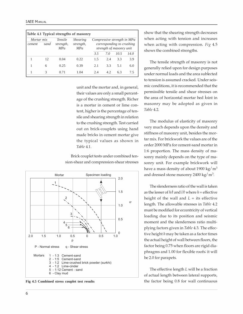
unit and the mortar and, in general,their values are only a small percent-age of the crushing strength. Richeris a mortar in cement or lime con-tent, higher is the percentage of ten-sile and shearing strength in relationto the crushing strength. Test carriedout on brick-couplets using handmade bricks in cement mortar givethe typical values as shown inTable 4.1.
Brick couplet tests under combined ten-sion-shear and compression-shear stresses
show that the shearing strength decreaseswhen acting with tension and increaseswhen acting with compression. Fig 4.5shows the combined strengths.
The tensile strength of masonry is notgenerally relied upon for design purposesunder normal loads and the area subjectedto tension is assumed cracked. Under seis-mic conditions, it is recommended that thepermissible tensile and shear stresses onthe area of horizontal mortar bed joint inmasonry may be adopted as given inTable 4.2.
The modulus of elasticity of masonryvery much depends upon the density andstiffness of masonry unit, besides the mor-tar mix. For brickwork the values are of theorder 2000 MPa for cement-sand mortar in1:6 proportion. The mass density of ma-sonry mainly depends on the type of ma-sonry unit. For example brickwork willhave a mass density of about 1900 kg/m3
and dressed stone masonry 2400 kg/m3.
The slenderness ratio of the wall is takenas the lesser of h/t and l/t where h = effectiveheight of the wall and L = its effectivelength. The allowable stresses in Table 4.2must be modified for eccentricity of verticalloading due to its position and seismicmoment and the slenderness ratio multi-plying factors given in Table 4.3. The effec-tive height h may be taken as a factor timesthe actual height of wall between floors, thefactor being 0.75 when floors are rigid dia-phragms and 1.00 for flexible roofs; it willbe 2.0 for parapets.
The effective length L will be a fractionof actual length between lateral supports,the factor being 0.8 for wall continuous
Table 4.1 Typical strengths of masonry
Mortar mix Tensile Shearing Compressive strength in MPacement sand strength, strength, corresponding to crushing
MPa MPa strength of masonry unit
3.5 7.0 10.5 14.0
1 12 0.04 0.22 1.5 2.4 3.3 3.9
1 6 0.25 0.39 2.1 3.3 5.1 6.0
1 3 0.71 1.04 2.4 4.2 6.3 7.5
Fig 4.5 Combined stress couplet test results

7
BUILDINGS IN FIRED-BRICK AND OTHER MASONRY UNITS
with cross walls or buttresses at both ends,1.0 for continuous at one end and sup-ported on the other and 1.5 for continuousat one and free at the other.
4.4 GENERAL CONSTRUCTIONASPECTS4.4.1 MortarSince tensile and shear strength are impor-tant for seismic resistance of masonry walls,use of mud or very lean mortars will beunsuitable. A mortar mix cement: sandequal to 1:6 by volume or equivalent instrength should be the minimum. Appro-priate mixes for various categories of con-struction are recommended in Table 4.4. Useof a rich mortar in narrow piers betweenopenings will be desirable even if a leanmix is used for walls in general.
4.4.2. Wall enclosureIn load bearing wall construction, the wallthickness �t� should not be kept less than190 mm, wall height not more than 20 t andwall length between cross-walls not morethan 40 t. If longer rooms are required, ei-ther the wall thickness is to be increased, orbuttresses of full height should be providedat 20 t or less apart. The minimum dimen-sions of the buttress shall be as thicknessand top width equal to t and bottom widthequal to one sixth the wall height.
4.4.3 Openings in wallsStudies carried out on the effect of open-ings on the strength of walls indicate thatthey should be small in size and centrallylocated. The following are the guidelineson the size and position of openings:
Table 4.3 Stress factor for slenderness ratio and eccentricity of loading
Slenderness Stress factor, K, for eccentricity ratio, e/t Remarksratio 0 0.04 0.10 0.20 0.30 0.33 0.50
6 1.000 1.000 1.000 0.996 0.984 0.980 0.970 Linear interpolation
8 0.920 0.920 0.920 0.910 0.880 0.870 0.850 may be used.
10 0.840 0.835 0.830 0.810 0.770 0.760 0.730
12 0.760 0.750 0.740 0.706 0.664 0.650 0.600
14 0.670 0.660 0.640 0.604 0.556 0.540 0.480 Values for e/t = 0.5 are
16 0.580 0.565 0.545 0.500 0.440 0.420 0.350 for interpolation only
18 0.500 0.480 0.450 0.396 0.324 0.300 0.230
21 0.470 0.448 0.420 0.354 0.276 0.250 0.170
24 0.440 0.415 0.380 0.310 0.220 0.190 0.110
Table 4.2 Typical permissible stresses
Mortar mix or equivalent Permissible stresses Compression for strength of unit, MPa
cement lime sand tension shear 3.5 7.0 10.5 14.0MPa MPa
1 - 6 0.05 0.08 0.35 0.55 0.85 1.00
1 1 6 0.13 0.20 0.35 0.70 1.00 1.10
1 - 3 0.13 0.20 0.35 0.70 1.05 1.25

8
IAEE MANUAL
(i) Openings to be located away fromthe inside corner by a clear distanceequal to at least 1/4 of the height ofopenings but not less than 60 cm.
(ii) The total length of openings not toexceed 50 percent of the length of the
wall between consecutive cross wallsin single-storey construction, 42 per-cent in two-storey construction and33 percent in three storey buildings.
(iii) The horizontal distance (pier width)between two openings to be not lessthan half the height of the shorteropening, Fig 4.6, but not less than60 cm.
(iv) The vertical distance from an open-ing to an opening directly above itnot to be less than 60 cm nor lessthan 1/2 of the width of the smalleropening, Fig 4.6.
(v) When the openings do not complywith requirements (i) to (iv), they
Fig 4.6 Recommendation regarding openings in bearing walls
Table 4.4 Recommended mortar mixes
Category of Proportion of cement-lime-sandconstruction*
I Cement-sand 1:4 or cement-lime-sand 1:1:6 or richer
II Cement-lime-sand 1:2:9 or richer
III Cement-sand 1:6 or richer
IV Cement-sand 1:6 or lime-cinder** 1:3 or richer
Notes:* Category of construction is defined in Table 3.1.
** In this case some other pozzolonic material like trass (Indonesia)and surkhi (burnt brick fine powder in India) may be used in placeof cinder.

9
BUILDINGS IN FIRED-BRICK AND OTHER MASONRY UNITS
should either be boxed in reinforcedconcrete alround or reinforcing barsprovided at the jambs through theMasonry, Fig 4.7.
4.4.4 Masonry bondFor achieving full strength of masonry theusual bonds specified for masonry shouldbe followed so that the vertical joints are
Fig 4.7 Strengthening of masonry around openings

10
IAEE MANUAL
broken properly from course to course. Thefollowing deserves special mention.
Vertical joint betweenperpendicular wallsFor convenience of construction, buildersprefer to make a toothed joint which is
Fig 4.8 A typical detail of masonry
many times left hollow and weak. To ob-tain full bond it is necessary to make a slop-ing (stepped) joint by making the cornersfirst to a height of 600 mm and then build-ing the wall in between them. Otherwise,the toothed joint should be made in boththe walls alternately in lifts of about 45 cm,Fig 4.8.
4.5 HORIZONTALREINFORCEMENT IN WALLSHorizontal reinforcing of walls is requiredfor imparting to them horizontal bendingstrength against plate action for out ofplane inertia load and for tying the perpen-dicular wall together. In the partition walls,horizontal reinforcement helps preventingshrinkage and temperature cracks. The fol-lowing reinforcing arrangements are nec-essary.
4.5.1 Horizontal bands or ringbeamsThe most important horizontal reinforcing
Table 4.5 Recommendation for steel in RC band
Longitudinal steel in R.C. bandsSpan, m category I category II category III category IV
no of diameter of no of diameter of no of diameter of no of diameter ofbars bars, mm bars bars, mm Bars Bars, mm Bars Bars, mm
5 2 12 2 10 2 10 2 10
6 2 16 2 12 2 10 2 10
7 2 16 2 16 2 12 2 10
8 4 12 2 16 2 16 2 12
9 4 16 4 12 2 16 2 12
Notes: (i) Width of the RC band is assumed to be the same as the thickness of wall. Wall thickness shall be 20 cm minimum. Acover of 25 mm from face of wall will be maintained. For thicker walls, the quantity of steel need not be increased.For thinner walls, see 4.7.
(ii) The vertical thickness of RC band may be kept minimum 75 mm where two longitudinal bars are specified and 150mm where four longitudinal bars are specified.
(iii) Concrete mix to be 1:2:4 by volume or having 15 MPa cube crushing strength at 28 days.
(iv) The longitudinal bars shall be held in position by steel links or stirrups 6 mm diameter spaced at 150 mm apart(see Fig 4.10 (a))
(v) Bar diameters are for mild-steel. For high strength must deformed bars, equivalent diameter may be used.
11
BUILDINGS IN FIRED-BRICK AND OTHER MASONRY UNITS
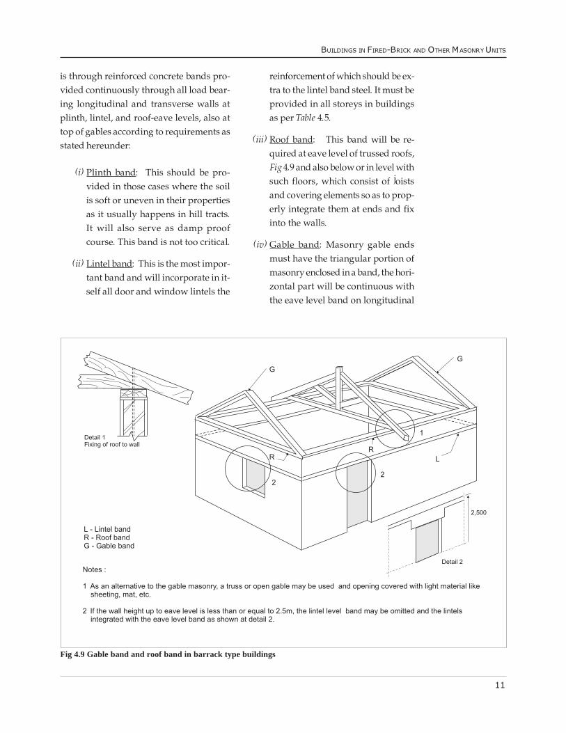
Fig 4.9 Gable band and roof band in barrack type buildings
is through reinforced concrete bands pro-vided continuously through all load bear-ing longitudinal and transverse walls atplinth, lintel, and roof-eave levels, also attop of gables according to requirements asstated hereunder:
(i) Plinth band: This should be pro-vided in those cases where the soilis soft or uneven in their propertiesas it usually happens in hill tracts.It will also serve as damp proofcourse. This band is not too critical.
(ii) Lintel band: This is the most impor-tant band and will incorporate in it-self all door and window lintels the
reinforcement of which should be ex-tra to the lintel band steel. It must beprovided in all storeys in buildingsas per Table 4.5.
(iii) Roof band: This band will be re-quired at eave level of trussed roofs,Fig 4.9 and also below or in level withsuch floors, which consist of joistsand covering elements so as to prop-erly integrate them at ends and fixinto the walls.
(iv) Gable band: Masonry gable endsmust have the triangular portion ofmasonry enclosed in a band, the hori-zontal part will be continuous withthe eave level band on longitudinal

12
IAEE MANUAL
walls, Fig 4.9.
4.5.2 Section of bands or ringbeamsThe reinforcement and dimensions of these
Fig 4.10 Reinforcement in RC band
bands may be kept as follows for wall spansupto 9 m between the cross walls or but-tresses. For longer spans, the size of bandmust be calculated.
A band consists of two (or four) longitu-dinal steel bars with links or stirrups em-bedded in 75 mm (or 50 mm), thick con-crete, Fig 4.10. The thickness of band maybe made equal to or a multiple of masonryunit and its width should equal the thick-ness of wall. The steel bars are located closeto the wall faces with 25 mm cover and fullcontinuity is provided at corners and junc-tions. The minimum size of band andamount of reinforcing will depend uponthe unsupported length of wall betweencross walls and the effective seismic coeffi-cient based on seismic zone, importance ofbuildings, type of soil and storey of thebuilding.
Appropriate steel and concrete sizes arerecommended for various buildings inTable 4.5. Such bands are to be located atcritical levels of the building, namely plinth,lintel, roof and gables according to require-ments (see 4.5.1).
4.5.3 Dowels at corners andjunctionsAs a supplement to the bands described in(a) above, steel dowel bars may be used atcorners and T-junctions to integrate the boxaction of walls. Dowels, Fig 4.11, are placedin every fourth course or at about 50 cmintervals and taken into the walls to suffi-cient length so as to provide the full bondstrength. Wooden dowels can also be usedinstead of steel. However, the dowels donot serve to reinforce the walls in horizon-tal bending except near the junctions.

13
BUILDINGS IN FIRED-BRICK AND OTHER MASONRY UNITS
Fig 4.11 (a) Corner-strengthening by dowel reinforcement placed in one joint (b) Corner-strengthening by dowelreinforcement placed in two consecutive joints. (c) T-junction - strengthening by dowel reinforcements(d) Strengthening by wire fabric at junction and corner

14
IAEE MANUAL
4.6 VERTICALREINFORCEMENT IN WALLSThe need for vertical reinforcing of shearwalls at critical sections was establishedin Para 2.6.7. The critical sections were thejambs of openings and the corners of walls.The amount of vertical reinforcing steel willdepend upon several factors like thenumber of storeys, storey heights, the effec-tive seismic coefficient based on seismiczone, importance of building and soil foun-dation type. Values based on rough esti-mates for building are given in Table 4.6 forready use. The steel bars are to be installedat the critical sections, that is the corners ofwalls and jambs of doors right, from thefoundation concrete and covered with ce-ment concrete in cavities made around themduring masonry construction. This concretemix should be kept 1:2:4 by volume or richer.Typical arrangements of placing the verti-cal steel in brick work are shown inFig 4.12.
The jamb steel was shown in Fig 4.7.The jamb steel of window openings will beeasiest to provide in box form around it.The vertical steel of opening may bestopped by embedding it into the lintel bandbut the vertical steel at corners and junc-tions of walls must be taken into the floorand roof slabs or roof band
The total arrangement of providing re-inforcing steel in masonry wall construc-tion is schematically shown in Fig 4.13.
4.7 FRAMING OF THIN LOADBEARING WALLSIf load-bearing walls are made thinner than200 mm, say 150 mm inclusive of plaster-ing on both sides, reinforced concrete fram-ing columns and collar beams are neces-sary which are constructed to have fullbond with the walls. Columns are to be lo-cated at all corners and junctions of wallsand at not more than 1.5 m apart but solocated as to frame up the doors and win-dows. The horizontal bands or ring beamsare located at all floors, roof as well as lin-tel levels of the openings. The sequence ofconstruction between walls and columnsis: first to build the wall upto 4 to 6 coursesheight leaving toothed gaps (tooth projec-tion being about 40 mm only) for the col-umns and second to pour 1:2:4 concrete tofill the columns against the walls usingwood -forms only or two sides. Needless tosay that column steel should be accuratelyheld in position all along. The band con-crete should be cast on the wall masonrydirectly so as to develop full bond with it.
Such construction may be limited to onlytwo storeys maximum in view of its verti-cal load carrying capacity. The horizontallength of walls between cross walls may be
Table 4.6 Recommendation for vertical steel at critical sections
No of Storeys Diameter of mild steel single bar in mm ateach critical section for category (1)
category I category II categoryIII category IV
One 16 12 12 Nil
Two Top 16 12 12 NilBottom 20 16 16 Nil
Three Top 16 12 12 NilMiddle 20 16 12 NilBottom 20 16 16 Nil
Four Top (2) (2) 12 12Third 12 12
Second 16 12Bottom 16 12
Notes: (i)Category of construction is defined in Table 3.1. Equivalentarea of twisted grip bars or a number of mild steel bars could beused but the diameter should not be less than 12 mm.
(ii) Four storeyed load bearing wall construction may not be usedfor categories I and II buildings.

15
BUILDINGS IN FIRED-BRICK AND OTHER MASONRY UNITS
Fig 4.12 Vertical reinforcement in walls

16
IAEE MANUAL
restricted to 7 m and the storey height to3 m.
4.8 REINFORCING DETAILSFOR HOLLOW BLOCKMASONRYThe following details may be followed inplacing the horizontal and vertical steel in
hollow block masonry using cement-sandor cement concrete blocks.
4.8.1 Horizontal bandU-shaped blocks may best be used for con-struction the horizontal bands at variouslevels of the storeys as per seismic require-ments, as shown in, Fig 4.14.
The amount of horizontal reinforcementmay be taken 25 percent more than thatgiven in Table 4.5 and provided by usingfour bars and 6mm dia stirrups. Other con-tinuity details shall be followed as shownin Fig 4.10.
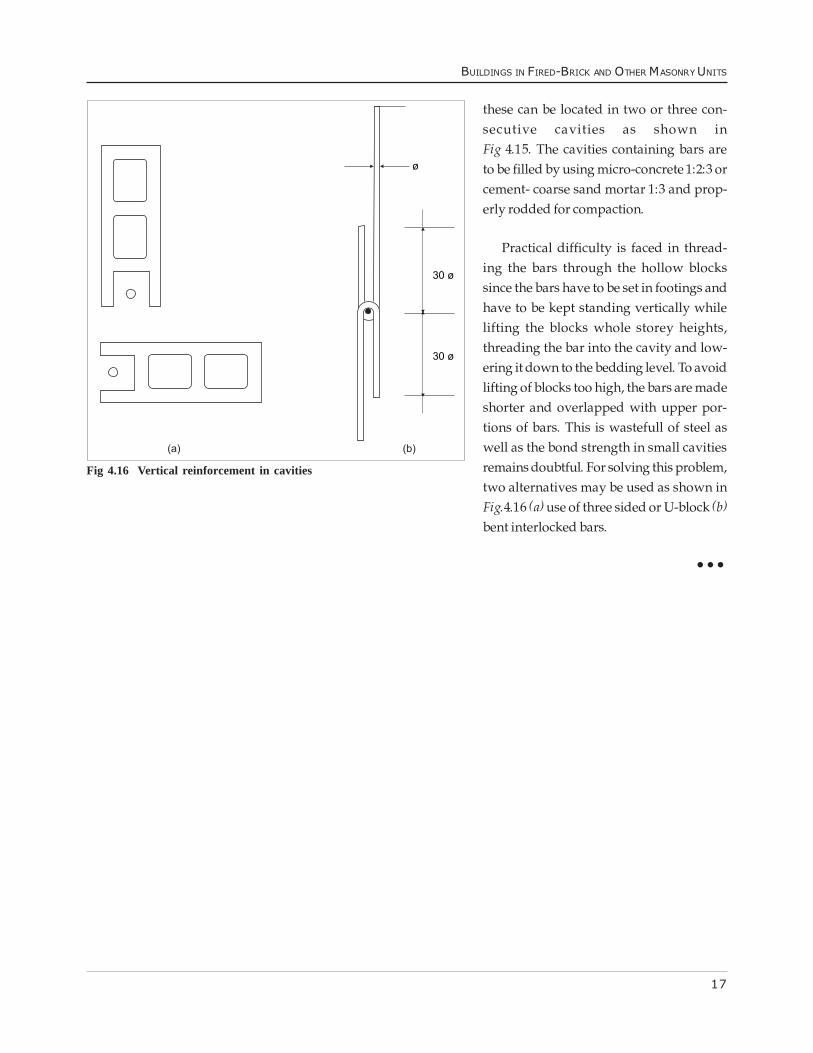
4.8.2 Vertical reinforcementThe vertical bars as specified in Table 4.6may conveniently be located inside thecavities of the hollow blocks, one bar in onecavity. Where more than one bar is planned,
Fig 4.14 U-blocks for horizontal bands
Fig 4.15 Vertical reinforcement in cavities
Fig 4.13 Overall arrangement of reinforcing masonry buildings
17
BUILDINGS IN FIRED-BRICK AND OTHER MASONRY UNITS
these can be located in two or three con-secutive cavities as shown inFig 4.15. The cavities containing bars areto be filled by using micro-concrete 1:2:3 orcement- coarse sand mortar 1:3 and prop-erly rodded for compaction.
Practical difficulty is faced in thread-ing the bars through the hollow blockssince the bars have to be set in footings andhave to be kept standing vertically whilelifting the blocks whole storey heights,threading the bar into the cavity and low-ering it down to the bedding level. To avoidlifting of blocks too high, the bars are madeshorter and overlapped with upper por-tions of bars. This is wastefull of steel aswell as the bond strength in small cavitiesremains doubtful. For solving this problem,two alternatives may be used as shown inFig.4.16 (a) use of three sided or U-block (b)bent interlocked bars.
���
Fig 4.16 Vertical reinforcement in cavities