synthesis of rtl descriptions for architecture t stuttgart algorithms for design automation...
TRANSCRIPT

Universität Stuttgart Algorithms for Design Automation ‐Mastering Nanoelectronic Systems
Synthesis of RTL Descriptions for Architecture Exploration Haupt Seminar
Yazan BOSHMAF
Advisor: Dipl.‐Inf. Tobias Bergmann
INFOTECH, ESE
Summer Semester 07

2
Table of Contents
List of Figures ................................................................................................................................................ 3
List of Tables ................................................................................................................................................. 3
1. Introduction .......................................................................................................................................... 4
2. Full System‐level Design Flow ............................................................................................................... 5
2.1 Architecture Exploration ............................................................................................................... 5
2.3 Architecture Design ....................................................................................................................... 7
3. Architecture Exploration at High Abstraction Levels ............................................................................ 7
3.1 Architecture Description Language (ADL) ..................................................................................... 8
3.1.1 What is ADL ........................................................................................................................... 8
3.1.2 Classification of ADLs ............................................................................................................ 8
3.1.3 ADLs and other languages ..................................................................................................... 9
3.2 ADLs for design space exploration .............................................................................................. 10
3.3 Case study: Architecture Implementation using ADL LISA ......................................................... 11
3.4 Case study: ASIP design ............................................................................................................... 13
4. RTL Synthesis for Architecture Exploration ........................................................................................ 13
4.1 The Automation Gap ................................................................................................................... 14
4.2 Proposed frameworks ................................................................................................................. 14
4.2.1 RTL (+) for LISA .................................................................................................................... 14
4.2.2 RTL(+) for EXPRESSION ........................................................................................................ 17
4.3 Improvements ............................................................................................................................. 19
4.4 Future work ................................................................................................................................. 21
5. Asynchronous design support ............................................................................................................. 21
5.1 Typical asynchronous design ...................................................................................................... 22
5.2 Transformation framework ......................................................................................................... 23
5.3 Asynchronous RTL for Architectural Exploration ........................................................................ 26
5.4 Future work ................................................................................................................................. 27
6. Conclusion ........................................................................................................................................... 27
7. References .......................................................................................................................................... 28

3
List of Figures Figure 1. System level design flow for embedded systems [Sam03] ............................................................ 5 Figure 2. The VCC design flow [Cad07] ......................................................................................................... 6 Figure 3. Design performance and parameters relationship [Bos98] ........................................................... 7 Figure 4. ADL‐driven design automation of embedded processor [Mis06] .................................................. 8 Figure 5. ADL vs. Non‐ADL Languages [Mis06] ............................................................................................. 9 Figure 6. ADL‐driven design space exploration [Kej03] .............................................................................. 10 Figure 7. ADL‐driven System‐level Design Flow [Kej03]............................................................................. 11 Figure 8. Exploration and implementation using LISA [Sch02] ................................................................... 12 Figure 9. LISA model and corresponding HDL model components [Hof01] ............................................... 12 Figure 10. Standard ASIP Architecture ........................................................................................................ 13 Figure 11. Enhanced Exploration and Implementation based on LISA [Sch04] .......................................... 14 Figure 12. Explicit hardware description [Sch04] ....................................................................................... 15 Figure 13. Implicit and non‐formalized hardware description [Sch04] ...................................................... 16 Figure 14. Transformation of resources [Sch04] ........................................................................................ 17 Figure 15. The EXPRESSION ADL [Kej03] ..................................................................................................... 18 Figure 16. A Fetch Unit [Kej04] ................................................................................................................... 18 Figure 17. Modified Architecture Exploration Framework using EXPRESSION [Kej04] .............................. 19 Figure 18. Decision minimization [Sch05] ................................................................................................... 20 Figure 19. Sharing multiplexer implementation [Sch05] ............................................................................ 21 Figure 20. Asynchronous Logic Package [Plo05] ......................................................................................... 24 Figure 21. Asynchronous OR Gate [Plo05] .................................................................................................. 24 Figure 22. The Asynchronous Library – Synthesized Asynch OR Gate[Plo05] ............................................ 25 Figure 23. Proposed asynch/RTL architecture exploration based on EXPRESSION framework ................. 26
List of Tables Table 1. LEON synthesis results [Sch04] ..................................................................................................... 17 Table 2. Synthesis results: RISC‐DLX vs. PEAS‐DLX [Kej04] ......................................................................... 19 Table 3. Performance Comparison [Sch05] ................................................................................................ 21 Table 4. Asynchronous LSI_10K Library [Plo05] .......................................................................................... 25 Table 5. Synthesis Results for 2‐Stage Pipelined Multiplier [Plo05] ........................................................... 26
4
1. Introduction As the demand for high performance computing and the competition between IC vendors increase, new approaches have to be investigated to automate the design cycle of embedded processors and new tools have to be developed to shorten the overall design time, resulting in shorter time to market. These new approaches and tools for design automation are to be applied at high abstraction levels of the system architecture to achieve rapid exploration and evaluation of candidate architectures based on power consumption, chip area, and performance constraints; considerations that are normally referred to at RT level and totally abandoned during high level architectural specification which may result in hardware design that doesn’t conform with the physical specifications forcing new repeated design cycles, thus wasting time and money.
Design automation tools currently used to achieve the automation between architecture specification and RT level description are either inflexible or don’t support full system architecture generation.
This paper states this automation gap more clearly by considering system‐level design flow and mapping it to architectural activities if possible. Also, current architecture exploration trends and recent research for synthesis driven architecture exploration are discussed. After that, the discussion is extended to support asynchronous circuit designs and a new framework is proposed. Several case studies are explained to get more practical perspective and to get a feeling of the improvement/automation.
At the end, some conclusions about the research in this field and future trends are discussed.
5
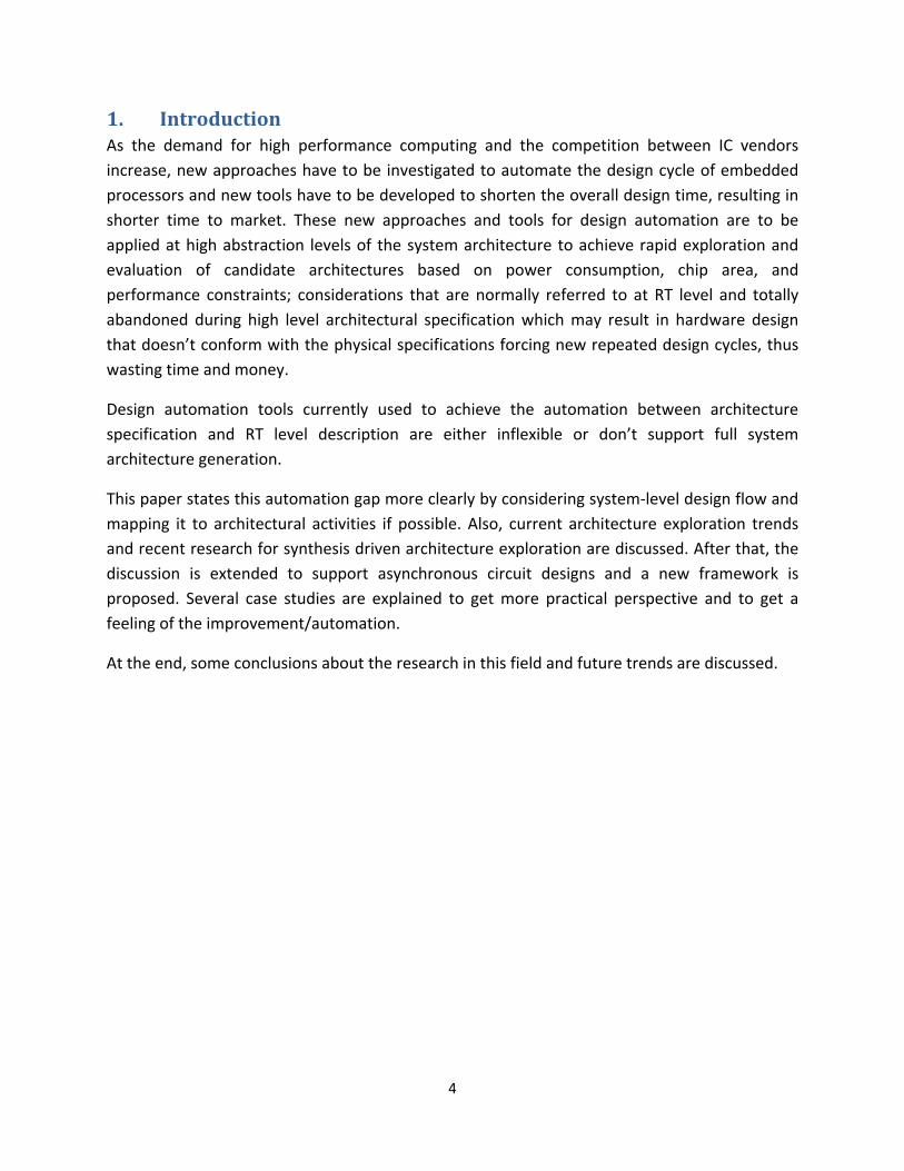
2. Full Systemlevel Design Flow The design of embedded systems is a complex and dynamic process that involves different tasks at different levels of abstraction. The design steps however can be grouped into two main tasks [Sam03]: architecture and design space exploration, and architecture design and RTL synthesis visualized in Figure 1 below.
Figure 1. System level design flow for embedded systems [Sam03]
At each task, the designer must meet and make sure to follow the design requirements like timing, power consumption, performance, chip area, and other business related constraints like design time and time to market.
2.1 Architecture Exploration The first step of any hardware design project consists of a contract between the end‐customer and the designer agreeing on the informal model of the application. Then, the system designer builds a formal model of the proposed system. The designer here can use behavior or functional model of the system that the end‐customer can understand and validate. After that, they agree on the architecture and partition the design into software part and hardware part. In order to get a specification model at this stage, and to do initial performance probing, the designer builds a simulation model using software, SystemC model for instance. Architecture exploration is used to formalize the following tasks:
• Fixes the specification of the hardware components by assigning them to known architectural blocks (selection of a specific processor among others, IP reuse …).
• HW/SW partitioning and mapping.
• Global communication structure of the system’s components.

6
The final result of this step is an abstract architecture that doesn’t contain all details about component interconnects and interfaces. It serves as a golden model for the next step; the actual architecture design (RTL design).
Formally defined, design space exploration is the process of analyzing several functionally equivalent alternatives to determine the most suitable one for system architecture. Efficient methods for design space explorations can be developed based on the principle of “separation of concerns”; the notions of correctness and performance should be separately defined. This notion can be extended to embedded systems that do not satisfy the synchronous assumption inside their boundaries but only at the interface with the environment [Hsi00].
Architecture design space exploration task can be automated using today’s EDA tools. An example is Cadence Virtual Component Co‐design (VCC) [Cad07] with the design flow visualized in Figure 2 below.
Figure 2. The VCC design flow [Cad07]
The designer starts with behavior model of the system and another architectural model. These models are the input for the tool that does, with the system designer controlling this process, the mapping between these two models. This achieves HW/SW partitioning of the system.

7
Normally, the process is followed by simulation runs for performance and functional validation of the system.
An important issue in design space exploration is performance and design parameters tradeoffs. Figure 3 shows a simplified, idealized relationship between measured performances of the architecture for a range of parameter values that each represents particular choice. For optimum design, the designer should focus around Point II that represents the best trade‐off between a particular performance and parameter values [Bos98].
Parameter Values
Per
form
ance
HIGH
HIG
H
LOW
LOW
Point III
Point IPoint II
Figure 3. Design performance and parameters relationship [Bos98]
2.3 Architecture Design During this task, the system designer has to interconnect the system components (hardware and software) with respect to design requirements and constraints defined in the golden architecture model derived in the previous step. This step results in RTL architecture, also known as micro‐architecture that involves the tasks of:
• Component design. • Generation of all hardware and software interface details needed at pin‐and‐cycle
accurate model. This step has wide and huge support from EDA vendor (RTL design and synthesis tools).
3. Architecture Exploration at High Abstraction Levels Architecture exploration is typically done at high abstraction levels. Architecture Description Languages (ADLs) are used to perform architecture exploration for application‐driven designs.

8
3.1 Architecture Description Language (ADL)
3.1.1 What is ADL Modeling has a major role in the realization of design automation of embedded processors. Hence, the need for specification language at high abstract levels to describe and explore the design architectures is obvious. An ADL has to satisfy two basic requirements: First, it should be descriptive enough to capture the high‐level specification of the processor architecture. Second, should be simple enough to allow clear association between the specification and the architecture manual. Also, an ADL must provide a set of expected functionalities for design automation tasks such as exploration, simulation, compilation, synthesis, test generation, and validation. Such functionalities are hardware, test, and design‐toolkit generation visualized in figure 4 below.
Figure 4. ADL‐driven design automation of embedded processor [Mis06]
3.1.2 Classification of ADLs Today's ADLs can be classified based on two aspects: content and objective. Content classification is based on the nature of the information that an ADL can capture. On the other hand, objective classification is based on the purpose of the ADL itself. Further sub classifications exit.
This paper deals with the contents of the descriptions, so content‐based classification is more relevant. Content‐oriented classification of ADLs divides them into three categories: behavioral, structural, and mixed [Mis06].
3.1.2.1 Behavioral ADLs Behavioral ADLs are primarily used to capture instruction sets and are good for regular architectures and provide programmer’s view of the system. Still, they are not appropriate for irregular architectures and are hard for specifying pipelined designs. An example of behavior‐centric ADL is nML that was proposed by Technical University of Berlin, Germany.

9
3.1.2.2 Structural ADLs Structural ADLs are primarily used to capture the design architectural structure. Also used to specify pipelining, code generation, and architecture synthesis. An example of structure‐centric ADL is MIMOLA that was developed at University of Dortmund, Germany.
3.1.2.3 Mixed ADLs Mixed ADLs combine the benefits of both behavioral and structural ADLs. Also, they generate corresponding compilers/simulators for design automation. An example of mixed‐level ADL is LISA that was developed at Aachen University of Technology, Germany. Another famous mixed‐level ADL is EXPRESSION that was developed at University of California, Irvine, USA.
3.1.3 ADLs and other languages In principle, ADLs differ from programming languages because the latter connect all architectural abstraction to specific point solutions while ADLs purposely suppress or differ such binding. In general, architectures can be derived from code by reverse engineering. For example, it might be possible to reverse engineer a C/C++ code and decide whether it corresponds to a Fetch unit or not. Also, programming languages are not accepted choice for architecture description as they lack major hardware features like synchronization and parallelism. Compared to other modeling languages like UML, ADLs differ because the earlier are more concerned with the behavior of the whole design rather than the parts, whereas ADLs focus on the representation of the design components and modeling their behavior. Hardware Description Languages (HDL) like VHDL differ from ADLs because the earlier don't have sufficient abstraction to describe and explore architectures at the system level. Though in practice, some variants of HDLs can be used as ADLs for specific class of embedded processors [Mis06].
Figure 5. ADL vs. Non‐ADL Languages [Mis06]
To conclude, there's no specific and clear line between ADLs and non‐ADLs as shown in Figure 5. Still, the designer can distinguish between them based on which language was developed for which purpose. Languages that were developed for architectural description show clear advantage in this area over languages that have been modified to represent architectures.

10
3.2 ADLs for design space exploration Today’s market faces new challenges and strong competition. A shorter time to market is always preferred in any hardware design project. The complete design time is divided between the design tasks and in practice there is only little margin for design space exploration and finding the best‐in‐breed solution.
The development time can be decreased significantly by employing a re‐targetable approach during design space exploration by using machine description languages, namely, ADLs.
As illustrated in Figure 6, ADL‐driven design space exploration starts with the designer describing ADL specification for the system (processor core, memory…) and verifies it against the system specification. Then compiles and simulates the application that addresses the design.
Figure 6. ADL‐driven design space exploration [Kej03]
Other than design space exploration at high level, an ADL effects different tasks at different abstraction levels and results in accelerated overall design time and shorter time to market. Figure 7 visualize this usage.

11
Figure 7. ADL‐driven System‐level Design Flow [Kej03]
3.3 Case study: Architecture Implementation using ADL LISA Language for Instruction Set Architecture (LISA) was developed for automatic generation of reliable software development tools and synthesizable HDL code. That is, it’s used to bridge the gap between purely structural languages (VHDL or Verilog) and instruction set languages for architecture exploration purposes.
LISA supports the system‐level design flow discussed earlier. Figure 8 describes the architecture development process based on LISA. During the process of architecture exploration, the software development tools are formalized using high‐level languages (for instance C/C++) to describe the target architecture from the instruction set perspective, while Hardware Description Languages (HDL) (for instance VHDL or Verilog) are used to model the underlying hardware to be implemented in details.
Using this paradigm, the problems of consistency disappear and generated software development tools and HDL code are guaranteed to be correct by structure.

12
Figure 8. Exploration and implementation using LISA [Sch02]
Now, architecture implementation can be generated using LISA Processor Design Platform (LPDP). LPDP is an environment that provides automatic generation of software development tools for architecture exploration and application design, hardware/software co‐simulation interface, and hardware implementation. LPDP guarantees that the generated HDL model components can be fully compared to the LISA model component and visualized in Figure 9 below.
Resource Model
Memory Model
Instruction Set
Behavioral Model
Timing Model
Micro-Architecture
Structure
Functional Units
Memory Configuration
Decoder
Pipeline Controller
To HDL Model
To LISA ModelHDL Model
LISA Model
Figure 9. LISA model and corresponding HDL model components [Hof01]

13
As modern embedded processors are highly optimized for high speed, low power consumption, and small area size, the generated HDL has to fulfill these design requirements. In most cases, the code has to be optimized manually and custom design techniques have to be used for low power design and high speed operation. This paper discusses proposed frameworks to bridge this gap in design automation and is covered in later sections.
3.4 Case study: ASIP design ADLs are used to perform architecture exploration for application‐driven designs. An example of application‐driven designs is Application Specific Instruction Set Processors (ASIP). The concept of ASIP is that the system designer starts from a simple processor core then finds new macro instructions to enhance performance and reduce code size. These macro instructions are application specific and uses dedicated hardware for speed up. The process can is illustrated in Figure 10 below.
Figure 10. Standard ASIP Architecture
A typical ADL‐based ASIP design involves four basic tasks: architecture exploration, architecture implementation, application software design, system integration and verification.
Recent research suggests Object Oriented (OO) approach for complete ASIP design [Gou03] and ADL‐based ASIP design [Hof01].
4. RTL Synthesis for Architecture Exploration Being able to generate synthesizable RTL description from architecture description during architecture exploration phase of system design is not something new to design automation. As mentioned before, some commercial EDA tools provide this level of automation but are either inflexible or don’t support full system synthesis. Also, in practice, the generated RTL code doesn’t reflect design specific physical requirements like power consumption and area. It’s almost true that the system designer has to optimize the generated code and involve custom‐design tasks.

14
4.1 The Automation Gap As RT level is the commonly accepted level for hardware implementation, design parameters such as timing, area or power consumption can’t be taken into consideration accurately during design space exploration, especially in high level abstraction. The need for synthesis tools that maintain the full flexibility of ADLs, while being able to generate complete architecture on RT level is becoming hot research area and currently represents a gap in design automation.
4.2 Proposed frameworks Two major approaches for automatic generation of synthesizable HDL have been proposed: generic parameterized processor cores based‐approach and processor specification languages (formally known as ADLs) based‐approach.
Generic parameterized processor cores based‐approach is limited to specific core templates whose toolkits can be enhanced to a certain degree. An example of this approach is Xtensa [Ten07] and Jazz [Imp07].
Concerning the second approach, several frameworks have been proposed that address this issue and all of them follow the same concept to bridge the gap using enhanced RTL aware ADLs. This paper discusses two frameworks that use two different ADLs; LISA [Sch04] and EXPRESSION [Kej03] [Kej04].
4.2.1 RTL (+) for LISA LISA framework has been discussed in the previous sections. Referring to Figure 11, an additional framework is added to LISA’s exploration and implementation cycle to take the gate‐level synthesis results into account during the exploration phase where a complete hardware model is generated to get first estimation about clock speed, power consumption, and area.
Figure 11. Enhanced Exploration and Implementation based on LISA [Sch04]

15
Using this paradigm, for the first time the designer is able to conduct this synthesis flow without being limited by tight flexibility, whereas in the previous methods, this flow was formalized by predefined RTL components and/or architectural templates.
LISA features great dynamic flexibility by giving the designer the ability to define the state transition of the architecture in ANSI‐C code. In order to bridge the gap between LISA ADL and the RT‐level without restraining the current flexibility, an ANSI‐C compatible hardware modeling language is to be chosen. Thus, SystemC was selected as a hardware description language for this framework.
LISA defines three different types of hardware descriptions:
1. Explicit hardware description: This type of hardware description results from language elements with a well defined semantics. As a result, they describe the underlying hardware without any ambiguity. The equivalent RTL hardware can be generated directly from given LISA model. Figure 12 below is an example of explicit hardware description in LISA.
Figure 12. Explicit hardware description [Sch04]
2. Implicit hardware description: This type of hardware description results from language elements that are not self‐descriptive concerning their semantically meaning, that is, they don’t have a well defined semantics. Hardware generation for this kind of language elements requires an in‐depth analysis of the complete model and even sometimes extra information that is not included in the model is needed to be taken into account (for instance, the knowledge about the simulation scheduler). This can be explained by the LISA timing model which is based on the so‐called “activation” of LISA operations. An activated operation is marked for execution and executed by the simulation scheduler at the correct point of time. To derive the RTL decoder, the ACTIVATION sections of the LISA model and the simulation scheduler have to be taken into account. A code snippet is visualized in figure 13. Note in this figure that the OPERATION

16
“decode” activates “instr” which leads to the activation of OPERATION “add” or OPERATION “sub”. To generate the hardware that corresponds to this behavior, a pipeline controller has to be realized with the same behavior as the simulation scheduler.
OPERATION decode in pipe.DC { DECLARE { GROUP instr = { add || sub }; } BEHAVIOR { PIPELINE_REGISTER (p, DC/EX).a = R1;
PIPELINE_REGISTER (p, DC/EX).b = R2;}
ACTIVATION { instr }}OPERATION add in pipe.EX { DECLARE { INSTANCE writeback; } BEHAVIOR { PIPELINE_REGISTER (p, EX/WB).r =
PIPELINE_REGISTER (p, DC/EX).a + PIPELINE_REGISTER (p, DC/EX).b;}
ACTIVATION { writeback }}OPERATION sub in pipe.EX { DECLARE { INSTANCE writeback; } BEHAVIOR { PIPELINE_REGISTER (p, EX/WB).r =
PIPELINE_REGISTER (p, DC/EX).a - PIPELINE_REGISTER (p, DC/EX).b;}
ACTIVATION { writeback }}OPERATION writeback in pipe.WB { BEHAVIOR { R = PIPELINE_REGISTER (p, EX/WB).r; }}
Figure 13. Implicit and non‐formalized hardware description [Sch04]
3. Non‐formalized hardware description: The datapath of the architecture is modeled by the BEHAVIOR section in LISA specification. The BEHAVIOR section mainly consists of plain ANSI‐C code that is extended by LISA language constructs. In Figure 13 above, the LISA keyword PIPELINE_REGISTER is embedded into the ANSI‐C behavior description of the “add” and “sub” operations. Thus, the BEHAVIOR section can be considered as non‐formalized hardware description that is used to generate complete architecture from LISA descriptions using ANSI‐C SystemC, which is not different from VHDL or Verilog for gate level synthesis.
The proposed framework converts LISA BEHAVIOR description into SystemC code that reflects exact behavior of the design component and follows the design requirements like power consumption, timing, and area. Figure 14 illustrate this mapping. The postfix (_out or _in)

17
represents the SystemC port direction. (REG) represents the data, (AW) the address, and (EW) an enable signal.
Figure 14. Transformation of resources [Sch04]
One problematic issue faced by this framework is resource sharing between different components; a problem that can be solved by analyzing the ANSI‐C code of the model concerning the underlying hardware and mutual exclusion of operations.
Put into practice, a number of simulation have been conducted using this framework. One of them is an implementation of an integer pipeline and memory configuration for the LEON1 processor. The framework has managed to achieve impressive results as shown in Table 1:
Handwritten LEON (ns) Generated LEON (KGates) Ratio
Timing 3.08 4.4 1.44
Gates 16.7 37 2.22
Table 1. LEON synthesis results [Sch04]
4.2.2 RTL(+) for EXPRESSION The framework proposed guarantees automatic generation of synthesizable HDL design and software toolkit from a single specification language, namely EXPRESSION, which will be an efficient solution for rapid exploration of pipelined embedded processors.
EXPRESSION was developed for automatic software toolkit generation, including compiler, simulator, and assembler. EXPRESSION is an architecture specification language and the toolkit is generated automatically from the ADL descriptions [Hal99]. The application programs are compiled and simulated, and the feedback is used to modify the ADL specification of the architecture.
Figure 15 illustrates the idea that EXPRESSION ADL captures the structure, behavior, and the mapping (structure and behavior) of the programmable architecture.

18
Figure 15. The EXPRESSION ADL [Kej03]
The structure of a processor can be illustrated by a graph with nodes representing the system components (registers, ALUs), and edges as component connectivity (bus system, pipeline buffers). The behavior of a processor is structured into operation groups, with each group consisting of a set of operations having some common characteristics. Each operation is described by its op‐code, operands, behavior and instruction format.
Compared to the previous framework, the concept is the same but EXPRESSION was preferred over LISA because by using LISA the designer has to manually realize the datapath components with a main problem being the design verification where the operations have to be described and maintained twice, the LISA model and the HDL model of handwritten datapath.
This framework is able to effectively explore a broad range of pipelined architectures representing heterogeneous architectural styles as well as memory subsystems by utilizing functional abstraction technique achieved by the usage of generic sub‐functions for architecture description.
Figure 16 shows a code snippet illustrating the notion of generic sub‐functions that allows the flexibility of specifying the system in more details and component reuse and pre‐verification.
Figure 16. A Fetch Unit [Kej04]
The framework can be illustrated using Figure 17 below. System designer starts with initial ideas about the system architecture (processor, coprocessor, memory…) for the specified

19
applications. After that, the designer develops an architectural specification document based on experience and available prototypes. Now, the first step in the proposed architecture exploration framework is to specify and validate the architecture in EXPRESSION ADL. Then, the application program is compiled and simulated against the toolkit generated from the specifications. The output of this step is used to answer some questions about the instruction set, algorithm’s performance, and memory space requirements. The necessary silicon area, clock frequency, or power consumption can only be determined by generating synthesizable HDL model which is done by the HDL generator that is capable of composing heterogeneous architectures using functional abstraction primitives.
Figure 17. Modified Architecture Exploration Framework using EXPRESSION [Kej04]
The generated HDL code consists of three major parts: instruction decoder, datapath, and control logic.
The framework was practically validated by generating synthesizable HDL description and performing rapid exploration of the DLX architecture [Hen06]. The ADL written specification for RISC‐DLX is compared to hand written PEAS‐DLX discussed in [Ito00]. The comparison is shown in Table 2 below.
Spec (words) HDL Code (words) Area (gates) Speed (MHz)
RISC‐DLX 2063 6612 118 K 33
PEAS‐DLX 1196 6259 105 K 5.3
Table 2. Synthesis results: RISC‐DLX vs. PEAS‐DLX [Kej04]
4.3 Improvements The approaches discussed above, while allowing fast design space exploration due to high level of abstraction, often degrade or compromise the performance or quality of the final system

20
implementation resulting in limited use of design automation tools that support synthesizable RTL generation from ADL‐driven architecture exploration.
An optimization technique was proposed for LISA‐based automatic RTL generation [Sch05]. This optimization is carried out during RTL processor synthesis and is categorized as structural and behavioral.
The behavioral optimization eliminates the overhead inherent in a conceptual software‐like description, while mapping to an RTL one. This implies optimization techniques which are similar to those done by a compiler like constant folding. Figure 18 shows decision minimization optimization technique.
If (cc) {R[idx] = value;
}
If (cc) thenR(write,addr) <= idx;R(write,value) <= value;R(write,enable) <= 1;
endif;
R(write,addr) <= idx;R(write,value) <= value;
If (cc) thenR(write,enable) <= 1;
endif;
R(write,addr) R(write,enable)R(write,value)
cc cc cc
idx ... value ... 1 ...
R(write,enable)
1 ...
R(write,value) R(write,addr)
idx value
LISA model: Behavior Section
Gate Level ImplementationGenerated RTL (VHDL)
Optimized RTL (VHDL)
RTL Synthesis
Optimization
cc
Figure 18. Decision minimization [Sch05]
The structural optimization makes use of the explicit exclusiveness between different parts of a single instruction and exclusiveness between different instructions of the processor. Figure 19 shows path sharing optimization.

21
a b c d
enable(a)
enable(b)
enable(c)
enable(d)
Encoding-based Multiplixer
a b c d
Sharing Multiplixer
Figure 19. Sharing multiplexer implementation [Sch05]
Table 3 shows the area and the timing delay of three different implementations (unoptimized, optimized and original) of the RTL description of ICORE from Infineon and ISS‐68HC11 from Motorola.
Architecture Version Area (K Gates) Clock Period (nsec)
ISS‐68HC11 (unopt.) 24.52 5.82
ISS‐68HC11 (opt.) 19.55 5.57
Original M68HC11 15.00 5.00
ICORE (unopt.) 50.85 6.07
ICORE (opt.) 39.40 6.08
ICORE hand‐written 42.00 8.00
Table 3. Performance Comparison [Sch05]
4.4 Future work Future work includes generating HDL models for real world architectures, automatic generation of pipelined functional units and optimization and resource sharing for EXPRESSION‐based automatic RTL generation framework where the execution units consumes 50‐60% of the total area and power [Kej03].
5. Asynchronous design support An asynchronous circuit is a circuit in which its parts are largely autonomous. They are not governed by a clock circuit or global clock signal, but instead need only wait for the signals that indicate completion of instructions and operations. These signals are specified by simple data

22
transfer protocols. This type of circuit design is getting a huge attention lately from industry and academic research hence design automation has to be extended to support it [Hau95].
5.1 Typical asynchronous design Asynchronous design has many advantages over synchronous design [Fur96]. The clock in a synchronous circuit runs all the time, causing transitions in the circuit that waste electrical power. An asynchronous design, on the other hand, only causes transitions in the circuit in response to a request to carry out useful work. It can switch instantaneously between zero power dissipation and maximum performance upon demand. In addition, asynchronous design avoids the problem of clock skew (clock signal arrives at different components at different times), which is becoming increasingly hard to control in clocked circuits. The final advantage is the intrinsic modularity of self‐timed designs. Data encapsulation, modularity and component reuse are of increasing interest in computer software and hardware design, where such characteristics are crucial to offset the costs of the increasingly sophisticated and complex products demanded by the market.
In a synchronous (clocked) chip, the clock controls all the state changes and communication within the chip. Between active clock edges combinatorial logic generates the next state function, possibly generating many false output values (glitches) on the way to the correct value, but so long as the outputs are correct and stable at the next active clock edge the chip will operate correctly. The timing constraints which the design must meet may be summarized as follows:
• All logic functions must be correct and stable before the next active clock edge.
• The clock must be clean and the clock period must be longer than the longest logic delay.
In addition, clock skew and slow clock edges can give rise to race conditions which can be avoided by careful latch design and controlling the clock skew and edge speeds carefully.
Asynchronous design styles work without a clock, though, there are two basic ways used in asynchronous logic to determine when the outputs from a combinational logic block are valid [Hau95]:
• Self‐timed logic: it uses a redundant logic representation where some output values represent valid logic values and others represent invalid values. The output must pass through an invalid value when changing from one valid value to another valid value. The simplest redundant form uses dual‐rail encoding, where each Boolean uses two wires. ‘00’ is the invalid value, ‘01’ represents ‘false’, ‘10’ represents ‘true’ and ‘11’ is unused.
• Delay matching logic: it employs conventional logic representation but includes an additional control wire which indicates when the output is valid. Usually a transition on the control wire is passed through logic which is known to have a delay no shorter than that through the combinatorial logic function.
Concerning signaling protocols, conventional logic design typically represents logic values by signal levels; a wire at ground potential represents a logic ‘0’ and at supply potential a logic ‘1’. Many asynchronous styles are similar, but it should be recognized that this is not the only

23
possibility. For instance, in a dual‐rail encoded system, a ‘0’ could be represented by a transition on one wire and a ‘1’ by a transition on the other. Since a transition is an event, there is now no need to pass through an invalid code between consecutive values. It is possible, though uncommon, to build complete logic systems on transitions. Now, it is useful to define two signaling protocols:
• Level signaling: here an event is indicated by a level (often logic ‘1’) and before the next event the wire must return to zero.
• Transition signaling: here an event is indicated by a change in logic level (either ‘0’ to ‘1’ or ‘1’ to ‘0’) and the next event is simply the opposite transition, so no recovery phase is required.
In the following section, a transformation framework is discussed to map synchronous circuits to asynchronous circuits at RTL level using HDL transformations. This transformation provides important advantage to asynchronous design where design automation tools for synchronous designs can be used now to automate and optimize asynchronous designs resulting in shorter design time and time to market.
5.2 Transformation framework As embedded systems design gets more complicated by increased demand to maximize the achievable system performance in least possible chip area and with a very small time to market window, the process design parameters gets more and more variable. This trend resulted in an increased difficulty to implement single clock scheme that is distributed and synchronized all over the chip.
One possible solution for this difficulty is to implement some (or all) of the design using asynchronous circuit which resulted in increased attention towards asynchronous circuit design after long disposal. Still, industries can’t switch to asynchronous design style because most of the system designer didn’t practice asynchronous circuit design and the fact that there’s a huge lack for design automation tools supporting asynchronous circuits. In addition, asynchronous design often ends up with unreliable design that is difficult to interface with synchronous design and consumes large area for hazard removal.
Another solution is to provide a direct transformation path from synchronous design to asynchronous design, where synchronous components are replaced with functionally equivalent asynchronous components. This transformation framework provides the following advantages:
• Complete synchronous to asynchronous IP block transformation.
• All asynchronous IP blocks are immune to process variability problem by using the dual‐rail self‐timing model.
• An extension to the existing design flow paradigms and tools.
• Saving money because no asynchronous circuit design training is needed.

24
This paper discusses such transformation framework that allows the designer to start with synchronous design and then transforms the complete system into asynchronous design using standard logic synthesis tools and a transformation script [Plo05].
In standard synthesis, the generated gate netlist is stored as HDL code (VHDL for instance) for simulation most likely using IEEE_Std_Logic_1164 library. Now, the transformer must go through the netlist and replace every st_logic type used by the synthesizer with dual‐rail asynchronous std_logic type, namely astd_logic. Dual‐rail is selected because it’s immune to process variations unlike single‐rail asynchronous handshaking style where we match the combinational logic delay with the same gates of the critical path or by using a set of inverters which result in sensitivity to process variations. Also, every logic gate in the netlist is replaced by an equivalent dual‐trail logic gate. So, there is a need for a package to define dual‐rail coding scheme and to overload the operators of all functions. Synthesizable VHDL simulation models for the target dual‐rail gates are needed too. These definitions are stored in a package astd_logic_1164 as shown in Figure 20 below.
type astd_logic is recordone: std_logic;zero: std_logic;
end record;
type astd_logic_vector is array (integer range <>) of astd_logic;
function “or“ (a, b: astd_logic) return astd_logic isvariable tmp: astd_logic;
begintmp.one := (a.zero AND b.one) OR
(a.one AND b.one) OR(a.one AND b.zero);
tmp.zero := a.zero AND b.zero;return tmp;
end “or“;
Asynchronous logic definition Operator overloading
LIBRARY astd_logic_1164
Figure 20. Asynchronous Logic Package [Plo05]
Every logic operator has to be mapped to the asynchronous equivalent and synthesized. Figure 21 shows an asynchronous OR gate. The output of this OR gate is (‘0’,’0’) if one of the inputs are (‘0’,’0’), (‘0’,’1’) if both inputs are (‘0’,’1’), and (‘1’,’0’) if one of the inputs are (‘1’,’0’). This can be checked by a simple Karnaugh‐map.
Figure 21. Asynchronous OR Gate [Plo05]
25
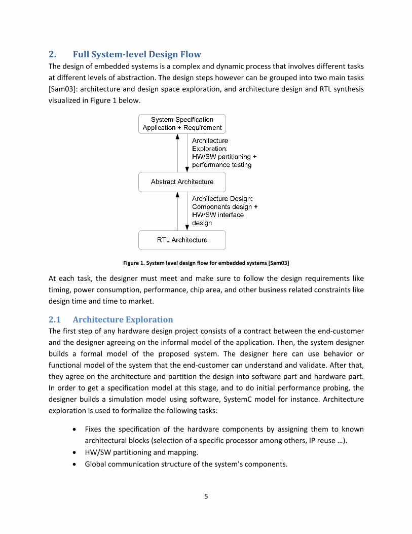
A sample of the synthesized logic is presented in Figure 22 below. The VHDL gate models are to be stored in a simulation library.
B<1:0>
A<1:0>
B<0>
B<1>
A<0>
A<1>
Z<1:0>Z<1>
Z<0>
Figure 22. The Asynchronous Library – Synthesized Asynch OR Gate[Plo05]
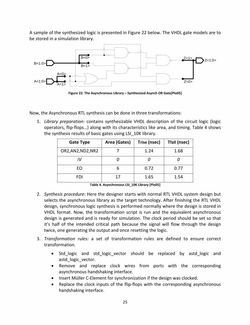
Now, the Asynchronous RTL synthesis can be done in three transformations:
1. Library preparation: contains synthesizable VHDL description of the circuit logic (logic operators, flip‐flops…) along with its characteristics like area, and timing. Table 4 shows the synthesis results of basic gates using LSI_10K library.
Gate Type Area (Gates) Trise (nsec) Tfall (nsec)
OR2,AN2,ND2,NR2 7 1.24 1.68
IV 0 0 0
EO 6 0.72 0.77
FDI 17 1.65 1.54
Table 4. Asynchronous LSI_10K Library [Plo05]
2. Synthesis procedure: Here the designer starts with normal RTL VHDL system design but selects the asynchronous library as the target technology. After finishing the RTL VHDL design, synchronous logic synthesis is performed normally where the design is stored in VHDL format. Now, the transformation script is run and the equivalent asynchronous design is generated and is ready for simulation. The clock period should be set so that it’s half of the intended critical path because the signal will flow through the design twice, one generating the output and once resetting the logic.
3. Transformation rules: a set of transformation rules are defined to ensure correct transformation.
• Std_logic and std_logic_vector should be replaced by astd_logic and astd_logic_vector.
• Remove and replace clock wires from ports with the corresponding asynchronous handshaking interface.
• Insert Müller C‐Element for synchronization if the design was clocked. • Replace the clock inputs of the flip‐flops with the corresponding asynchronous
handshaking interface.

26
To test the transformation framework, an asynchronous 2‐stage pipelined multiplier was constructed from RTL description. The results are displayed in Table 5.
Design Area (Gates) Trise (nsec) Tfall (nsec)
Synchronous multiplier (low effort) 723 16.88 17.07
Multiplier (low effort) 2997 28.90 29.01
Multiplier (high effort) 3632 21.13 21.10
16‐input C‐element (high effort) 50 3.40 3.76
Table 5. Synthesis Results for 2‐Stage Pipelined Multiplier [Plo05]
5.3 Asynchronous RTL for Architectural Exploration Now, with the proposed transformation framework, automatic synthesis of asynchronous circuits from synchronous RTL description is possible which can be used as an extension to the design space during architectural exploration at high level with fully automated asynchronous RTL synthesis as illustrated in Figure 19 below.
Evaluation S
tatistics (Perform
ance)E
valu
atio
n S
tatis
tics
(Are
a, P
ower
, Clo
ck F
requ
ency
)
Figure 23. Proposed asynch/RTL architecture exploration based on EXPRESSION framework
This specific automation step is not researched yet by any of the authors in [Plo05] or [Kej03] [Kej04] and can be proposed in a future paper.

27
5.4 Future work Current framework results in an area increase of approx. 4 times and delay increase of approx. 1.54 times. Methods to decrease chip area, power consumption, and delay for dual‐rail asynchronous logic are to be investigated in the future. Integration with RTL synthesis framework for architecture exploration is possible.
6. Conclusion As design automation tools currently used to achieve automation between architecture specification and RT‐Level are either inflexible or don’t support full system architecture generation, the need for synthesis driven architecture exploration is obvious. Also, a support for asynchronous circuit designs by design automation tools provides an alternative or extension for today’s complex synchronous design schemes.
Design automation is and will be a major part of the design process which results in reduced overall design cost and time to market, design uniformity, and increased standardization.

28
7. References
[Sam03] Firaz Samet, M. Anouar Dziri, Flavio Rech Wagner, Wander O. Cesário, Ahmed A. Jerraya: “Combining architecture exploration and a path to implementation to build a complete SoC design flow from system specification to RTL”, in proceedings of the ASP‐DAC, 2003, pp. 219 – 224.
[Hsi00] Harry Hsieh, Felice Balarin, Luciano Lavagno, Alberto Sangiovanni: “Efficient methods for embedded system design space exploration”, in proceedings of Design Automation Conference, 2000, pp. 607 – 612.
[Cad07] Cadence Design Systems, “Cadence Virtual Component Co‐design Modeling guide”, http://www.cadence.com/products/, 2007
[Bos98] Pradip Bose, Thomas M. Conte: “Performance Analysis and Its Impact on Design”, Computer, vol. 31, pp. 41‐49, May. 1998.
[Mis06]
Prabhat Mishra, Nikil Dutt: “Architecture Description Languages”, To appear in Customizable and Configurable Embedded Processors, Paolo Ienne and Rainer Leupers, Editors, Morgan Kaufmann Publishers, 2006.
[Kej03] Arun Kejariwal, Prabhat Mishra, Nikil Dutt: “Rapid Exploration of Pipelined Processors through Automatic Generation of Synthesizable RTL Models”, in proceedings of Rapid Systems Prototyping Workshop, pp. 226 – 232, 2003.
[Sch02] Oliver Schliebusch, Andreas Hoffmann, Achim Nohl, Gunnar Braun, Heinrich Meyr: “Architecture Implementation Using the Machine Description Language LISA”, in proceedings of conference on Asia South Pacific design automation/VLSI Design, p 239, 2002.
[Hof01] Andreas Hoffmann, Achim Nohl, Gunnar Braun, Oliver Schliebusch, Tim Kogel, H. Meyr: “A Novel Methodology for the Design of Application Specific Instruction Set Processors (ASIP) Using a Machine Description Language”, IEEE Transactions on Computers‐Aided Design, Nov. 2001.
[Gou03] Maziar Goudarzi, Shaahin Hessabi, Alan Mycroft: “Object‐Oriented ASIP Design and Synthesis”, in Forum on Specification and Design Languages, pp. 23‐26, Sept. 2003.
[Ten07] Tensilica Inc. http://www.tensilica.com/products/xtensa_LX.htm.
[Imp07] Improv Inc. http://www.improvsys.com/products/index.html.
[Sch04] Oliver Schliebusch, A. Chattopadhyay, R. Leupers, G. Ascheid, H. Meyr, et al.: “RTL Processor Synthesis for Architecture Exploration and Implementation”, in proceedings of Design Automation and Test in Europe Conference and Exhibition, vol. 3, pp. 156‐ 160, Feb. 2004.
[Kej04] Arun Kejariwal, Prabhat Mishra, Nikil Dutt: “Synthesis‐driven Exploration of Pipelined Embedded Processors”, in proceedings of VLSI Design 17th International Conference, pp. 921 – 926, 2004.

29
[Hal99] Ashok Halambi, Peter Grun, Vijay Ganesh, Asheesh Khare: “EXPRESSION: A Language for Architecture Exploration through Compiler/Simulator Retargetability”, in proceedings of Design Automation and Test in Europe Conference and Exhibition, pp. 485‐490, Mar. 1999.
[Hen06] John Hennessy, David Patterson: “Computer Architecture: A quantitative approach”, San Mateo, CA: Morgan Kaufmann Publishers Inc, 2006.
[Ito00] Makiko Itoh, Yoshinori Takeuchi, et al.: “Synthesizable HDL Generation for Pipelined Processors from a Micro‐Operation Description”, in IEICE Trans. Fundamentals, E00‐A(3), March 2000.
[Sch05] Oliver Schliebusch, Anupam Chattopadhyay, Ernst Martin Witte, David Kammler, Gerd Ascheid, Rainer Leupers, Heinrich Meyr: “Optimization Techniques for ADL‐driven RTL Processor Synthesis”, in proceedings of the 16th IEEE International Workshop on Rapid System Prototyping, pp. 165 – 171, 2005.
[Hau95] Scott Hauck: “Asynchronous Design Methodologies: An Overview”: in proceedings of the IEEE, vol. 83, No. 1, pp. 69 – 93, January, 1995.
[Fur96]
Steve Furber: “The Return of Asynchronous Logic”, in proceedings International Test Conference, pp. 938 – 946, 1996.
[Plo05] Juha Plosila, Johnny Oberg, Peeter Ellervee: “Automatic synthesis of asynchronous circuits from synchronous RTL descriptions”, in NORCHIP Conference, pp. 200‐ 205, 2005.