for pleasant healthy - dasco pleasant & healthy air-distribution iso 9001:2000 product bulletin...
TRANSCRIPT

for
Pleasant &HealthyAir-Distribution
ISO 9001:2000
ww
w.d
asco
.com
.kw
Product Bulletin 133-D Linear Slot Diffusers

Pleasant . . Serene. .YOU & DASCO.. .
www.dasco.com.kw
Partners for good health
Since 1964

Introduction
Linear slot diffusers are always considered as the most
attractive air distribution devices. They are specially
designed for ceiling mounting in a wide range of
applications in heating, ventilation and air conditionin
systems. At a perfect setting, linear slot diffusers provide a
stable pattern of diffusion to produce an optimum
performance for both supply and return air in addition to
their pleasant appearance.
To satisfy both architectural and engineering needs, curved
slot diffusers have been also developed and designed.
Whether it requires a continuous linear run, ellipse,
complete circle orserpentine curve,…. LINEAR/CURVED
SLOT DIFFUSERS CAN ALWAYS BE INCORPORATED
INTO ANY DESIGN.
INTRODUCTION
1
ww
w.d
asco
.com
.kw

Linear Slot Diffusers
Dasco linear slot diffusers for both supply and return applications DLD-C(S/R) are designed to give unobstrusive continuous air diffusion with a pleasing aesthetic appearance .Hairline joints ensure clean continuous runs of linear slot diffusers for both active and dummy sections. They are normally connected to the main ducting system by means of connection boxes (Plenums), and are adjustable in height for accurate lining-up with the ceiling.
LINEAR SLOT DIFFUSERS
2
GENERAL
Linear Slot Diffuser ( 3 Slots)
Linear Slot Diffuser ( 2 Slots)
Mitered Corner ( 90º )
In general , DLD-C(S/R) linear slot diffuser is considered as a unique type of an air distribution device, dispenses proper air quantities, controls air pattern for ultimate human comfort and adapts to any design concept perceived by architect / design engineer.
Linear Slot Diffusers
3
ww
w.d
asco
.com
.kw
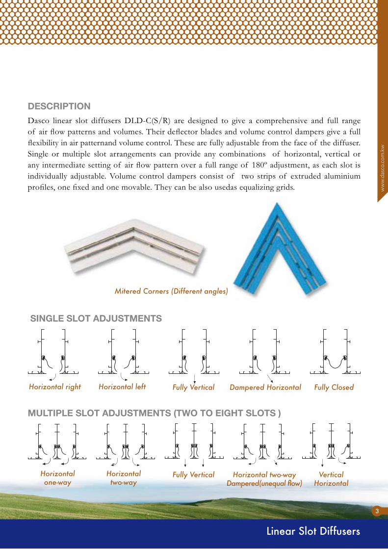
Dasco linear slot diffusers DLD-C(S/R) are designed to give a comprehensive and full range of air flow patterns and volumes. Their deflector blades and volume control dampers give a full flexibility in air patternand volume control. These are fully adjustable from the face of the diffuser. Single or multiple slot arrangements can provide any combinations of horizontal, vertical or any intermediate setting of air flow pattern over a full range of 180º adjustment, as each slot is individually adjustable. Volume control dampers consist of two strips of extruded aluminium profiles, one fixed and one movable. They can be also usedas equalizing grids.
DESCRIPTION
SINGLE SLOT ADJUSTMENTS
MULTIPLE SLOT ADJUSTMENTS (TWO TO EIGHT SLOTS )
Horizontal right Horizontal left Fully Vertical Dampered Horizontal Fully Closed
Horizontal one-way
Horizontal two-way
Fully Vertical Horizontal two-wayDampered(unequal flow)
Vertical Horizontal
Mitered Corners (Different angles)

Linear Slot Diffusers
4
Two types of linear slot diffusers are available:
MATERIAL & FINISH
Linear slot diffusers with 3/4” slot width.Linear slot diffusers with 1” slot width.
••Both are manufactured in one up to eight slots with a maximum one–piece length of 6 meters as a standard, permitting complete control of flow rate without disturbing the selected air pattern. Linear slot diffusers with other lengths and /or number of slots can also be provided on request.
End caps on both sides are supplied on one piece linear slot diffusers, and on one side of end sections of continuous units. Sections are connected by using alignment strips.
High quality and heavy gauge extruded aluminium profiles. They are available in white polyester powder coated finish. However, any other RAL standard colours are also available upon customer’s request.Deflector blades and dampers are also made from extruded aluminium profiles normally in black colour. Plenum boxes are made from galvanized steel.
LINEAR DIFFUSER (3-SLOTS) WITH DAMPERS

Linear Slot Diffusers
5
ww
w.d
asco
.com
.kw
Linear Slot Diffuser(Hexagonal Shape)
Linear Slot Diffuser(T-Shape)
Linear Slot Diffusers (2Slots)Special Geometric Shapes
Vertical outside Mitered corner section
Vertical inside Mitered corner section
Vertical inside Mitered corner sectionChamfered type
2 Slots DiffuserCircular Shape
Accessories
ACCESSORIES
6
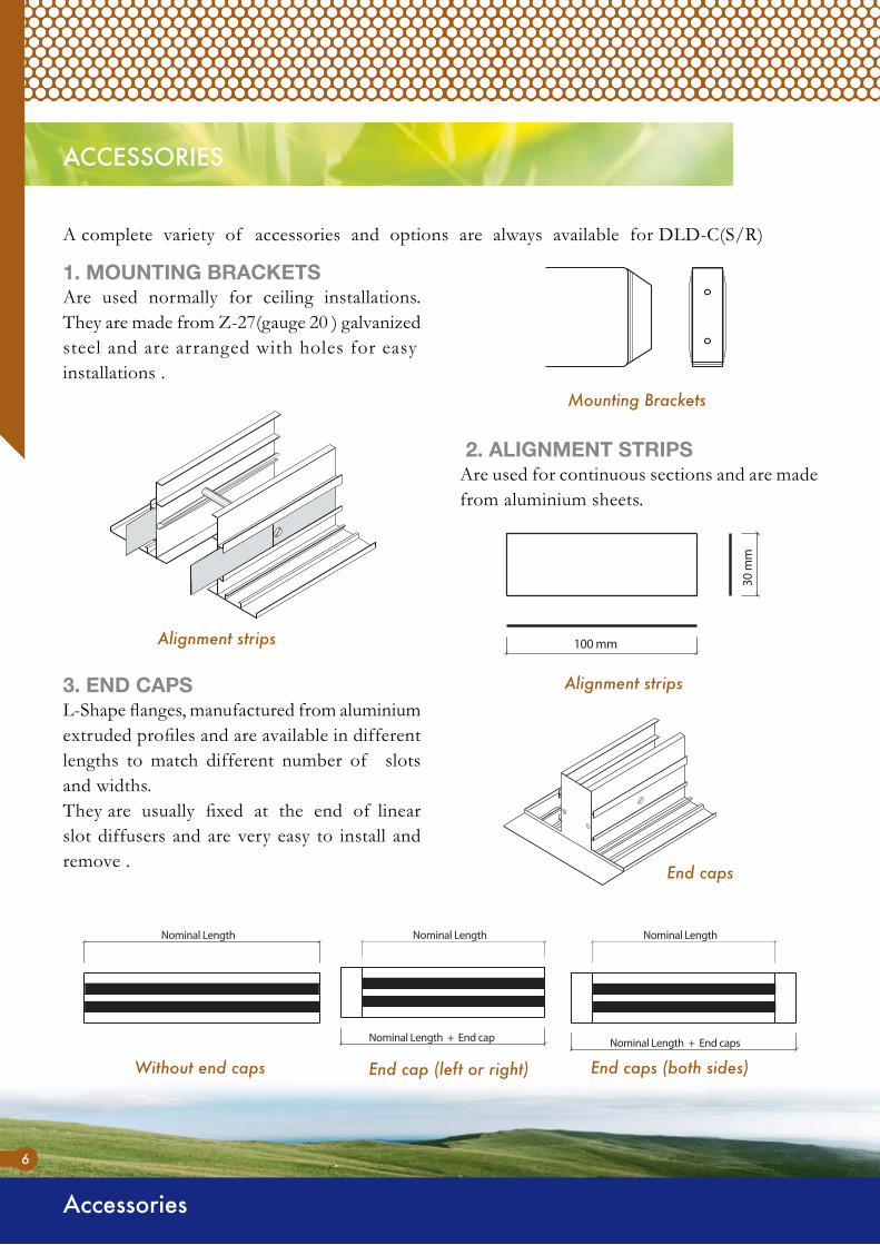
A complete variety of accessories and options are always available for DLD-C(S/R)
1. MOUNTING BRACKETSAre used normally for ceiling installations. They are made from Z-27(gauge 20 ) galvanized steel and are arranged with holes for easy installations .
2. ALIGNMENT STRIPSAre used for continuous sections and are made from aluminium sheets.
3. END CAPSL-Shape flanges, manufactured from aluminium extruded profiles and are available in different lengths to match different number of slots and widths.They are usually fixed at the end of linear slot diffusers and are very easy to install and remove .
Mounting Brackets
Alignment strips
Alignment strips
End caps
Without end caps End caps (both sides)End cap (left or right)

Accessories
7
ww
w.d
asco
.com
.kw
With exactly the same construction of supply air linear slot diffusers but with blank off damper sheets. Are used along with continuation sections of supply and /or return linear slot diffusers for decoration purposes.
4. DUMMY SECTIONS
Linear Diffuser (3 Slots) - Dummy Type
Are usually used when slot diffusers are designed to form closed loops. They are available in one to eight slots and can have any combination of L1, L2 and angle ø.
5. MITERED CORNERS
Mitered Corners
Plenum Boxes
PLENUM BOXES
8
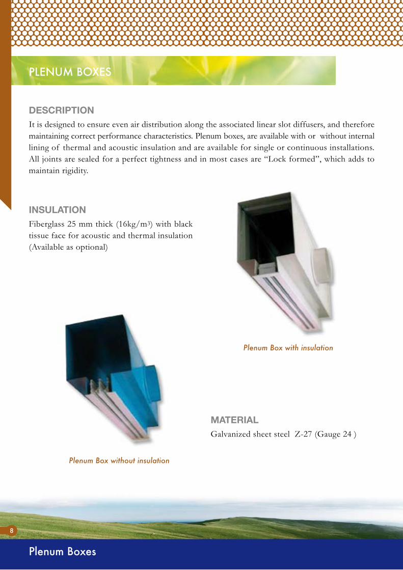
Plenum Box without insulation
It is designed to ensure even air distribution along the associated linear slot diffusers, and therefore maintaining correct performance characteristics. Plenum boxes, are available with or without internal lining of thermal and acoustic insulation and are available for single or continuous installations. All joints are sealed for a perfect tightness and in most cases are “Lock formed”, which adds to maintain rigidity.
DESCRIPTION
Fiberglass 25 mm thick (16kg/m3) with black tissue face for acoustic and thermal insulation (Available as optional)
INSULATION
Galvanized sheet steel Z-27 (Gauge 24 )
MATERIAL
Plenum Box with insulation
Plenum Boxes
9
ww
w.d
asco
.com
.kw
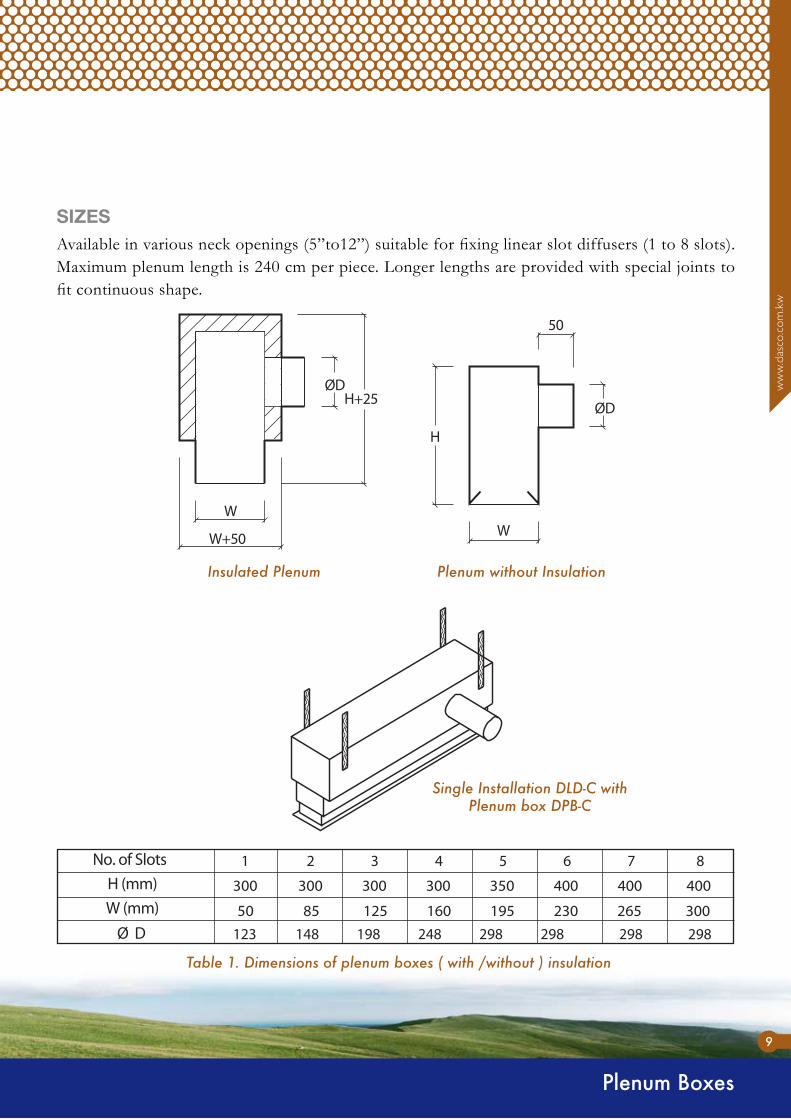
Insulated Plenum
Available in various neck openings (5”to12”) suitable for fixing linear slot diffusers (1 to 8 slots). Maximum plenum length is 240 cm per piece. Longer lengths are provided with special joints to fit continuous shape.
SIZES
Plenum without Insulation
Single Installation DLD-C withPlenum box DPB-C
Table 1. Dimensions of plenum boxes ( with /without ) insulation
Ordering Code
10
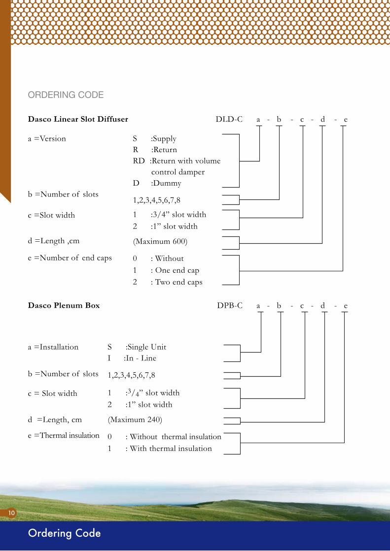
ORDERING CODE
DLD-C a - b - c - d - eDasco Linear Slot Diffuser
S :SupplyR :ReturnRD :Return with volume control damperD :Dummy
1,2,3,4,5,6,7,8
1 :3/4” slot width2 :1” slot width
(Maximum 600)
0 : Without1 : One end cap2 : Two end caps
a =Version
b =Number of slots
c =Slot width
d =Length ,cm
e =Number of end caps
DPB-C a - b - c - d - eDasco Plenum Box
S :Single UnitI :In - Line
1,2,3,4,5,6,7,8
1 :3/4” slot width2 :1” slot width
(Maximum 240)
0 : Without thermal insulation1 : With thermal insulation
a =Installation
b =Number of slots
c = Slot width
d =Length, cm
e =Thermal insulation

Dimensional Data
11
DIMENSIONAL DATA
ww
w.d
asco
.com
.kw
Linear slot diffuser with 3/4 “ slot width
Linear slot diffuser with 1” slot width

Dimensional Data
12
DIMENSIONS OF LISTED SIZES:
Table 2. Dimensions of linear slot diffusers with 3/4” slot width
a) Linear slot diffusers with 3/4” slot width
Table 3. Dimensions of linear slot diffusers with 1 “ slot width
a) Linear slot diffusers with 1” slot width
Curved DiffusersArched Shape
Woodall Colour

Engineering Data
13
ww
w.d
asco
.com
.kw
DEFINITIONS
ENGINEERING DATA
Table 4. CFM range for supply linear slot diffusers (1 to 8 slots).
Throw of an outlet, in m (feet), is the distance from the center of the
outlet to a point in the mixed air stream where the highest sustained
velocity of the mixed air stream has been reduced to a specified level,
i. e, 100 and 50 FPM.
• Throw (T) :
Is the air flow rate in cubic feet per minute.• CFM :Discharge or intake velocity of an outlet or inlet , in m/s (FPM) measured
with an approved calibrated velometer at specified locations relative to
the face of the outlet or inlet. Sometimes referred to as jet velocity.
• Velocity (Vk) :
Terminal velocity from an outlet, in m/s (FPM), is the highest sustained
velocity in the mixed air stream arbitrarily specified and used to
determine throw.
• Terminal velocity (Vt) :
Is the area factor of an outlet or inlet which is also a flow factor
determined from the discharge or intake velocity ( Vk ), and the volume
flow rate (CFM).
• Area factor (Ak) :
Ak =CFM
VkThe outward force within a duct measured in mm (inch) W.G.• Static Pressure (Ps) :
The forward moving force of an air stream within a duct measured in
mm ( inch) W.G.
• Velocity pressure (Pd) (Dynamic pressure)
:
The sum of the velocity pressure and static pressure measured in mm
(inch) W.G.• Total pressure (Pt) :
The following table could be helpful before starting the selection of a linear slot diffuser.

Noise Criteria
14
NOISE CRITERIA
The sound pressure level of 8 octave bands acceptable to human ears
and are estimated from table 5.
• Noise criteria :
The sound caused by an air outlet is directly proportional to the velocity
of the air passing through it.
ENVIRONMENTAL SOUND – Existing within the space with air
conditioning Equipment off
Ambient sounds a)
EXTERNAL SOUND – Entering a space from outdoors.b)
INTRUDING SOUND – Entering from adjacent spaces.c)
Prior to selection of NC level from table 5, the three ambient sounds above must be considered.
Is the difference between the sound power level of a terminal and the
sound pressure level sensed by human ears in the room, and is affected
by room size, sound absorption characteristic of the room surfaces,
ceiling height, space volume, distance of listener to terminal, terminal
location and number of terminals.
• The room effect :
Curved Slot Diffuser Concave Shape
Curved Slot DiffusersConvex Shape
Noise Criteria
15
ww
w.d
asco
.com
.kw
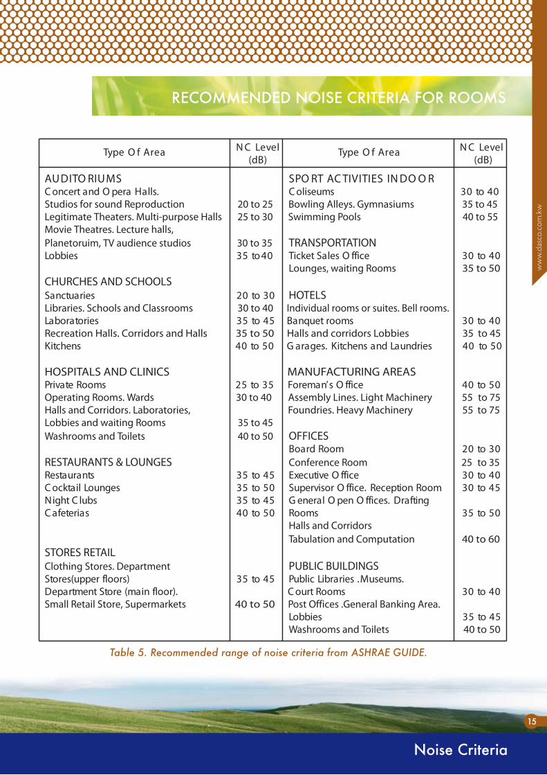
RECOMMENDED NOISE CRITERIA FOR ROOMS
Table 5. Recommended range of noise criteria from ASHRAE GUIDE.
Performance Data
16
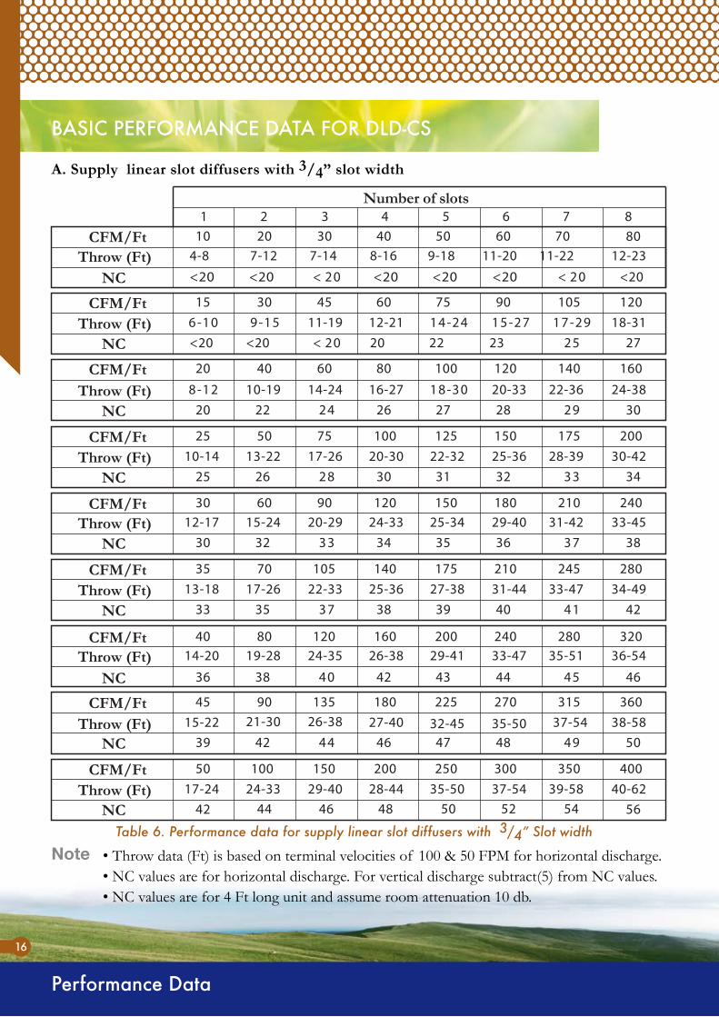
BASIC PERFORMANCE DATA FOR DLD-CS
Note
A. Supply linear slot diffusers with 3/4” slot width
1 2 3 4 5 6 7 8
CFM/Ft 8012-23
<20
Number of slots
NC
2010 30 40 50 60 704-8 7-147-12 8-16 9-18 11-20 11-22
<20 <20 <20 <20 <20 02<02<
18-3127
120
NC
CFM/Ft 3015 45 60 75 9092-7172-5151-9
<20 <20 20 22 23 5202<
10542-4101-6 12-2111-19
24-3830
160
NC
CFM/Ft 4020 60 80
20-33 22-3620 22 26 27 28 9242
140
03-8121-8 16-2714-24
100 120
10-19
30-4234
200
NC
CFM/Ft 5025 7525-36 28-39
25 26 30 31 32 3382
17522-3220-3017-26125 150
13-22100
10-14
33-4538
2406030 9029-40 31-42
30 32 34 35 36 7333
21025-3424-3320-29150 180
15-24120
12-17
NC
CFM/Ft
34-4942
280703531-44 33-47
33 35 38 39 40 1473
24527-3825-3622-33175 210
17-26140
13-18105
NC
CFM/Ft
36-54
46
320804033-47 35-51
36 38 42 43 44 5404
28029-4126-3824-35200 240
19-28160
14-20120
NC
CFM/Ft
38-5850
3609045
35-50 37-5439 42 46 47 48 9444
315
32-4527-4026-38225 270
21-30180
15-22135
NC
CFM/Ft
40-6242 44 48 50 5246 54 56
400
NC
5037-54 39-58
35035-5028-4429-40250 300
24-33200
17-24150100CFM/Ft
Throw (Ft)
Throw (Ft)
Throw (Ft)
Throw (Ft)
Throw (Ft)
Throw (Ft)
Throw (Ft)
Throw (Ft)
Throw (Ft)
Table 6. Performance data for supply linear slot diffusers with 3/4” Slot width
• Throw data (Ft) is based on terminal velocities of 100 & 50 FPM for horizontal discharge.• NC values are for horizontal discharge. For vertical discharge subtract(5) from NC values.• NC values are for 4 Ft long unit and assume room attenuation 10 db.

17
Performance Data
ww
w.d
asco
.com
.kw
EFFECTIVE FREE AREA (Ak)
Table 7. Effective free area Ak (Ft2 /Ft run) for DLC-CS (3/4” Slot width)
Note • Static pressure drop in inch W.G. for horizontal discharge. For vertical discharge multiply by 0.6
Number of Slots
Curve 1. Static pressure drop Vs. Air flow for DLD-CS (3/4” Slot width)
1 2 3 4 5 6 7 8
10 20 30 50 70 100 200 300
SupplyP.D.” W.G.
0.3
0.2
0.1
0.05
0.03
0.02
Performance Data
18
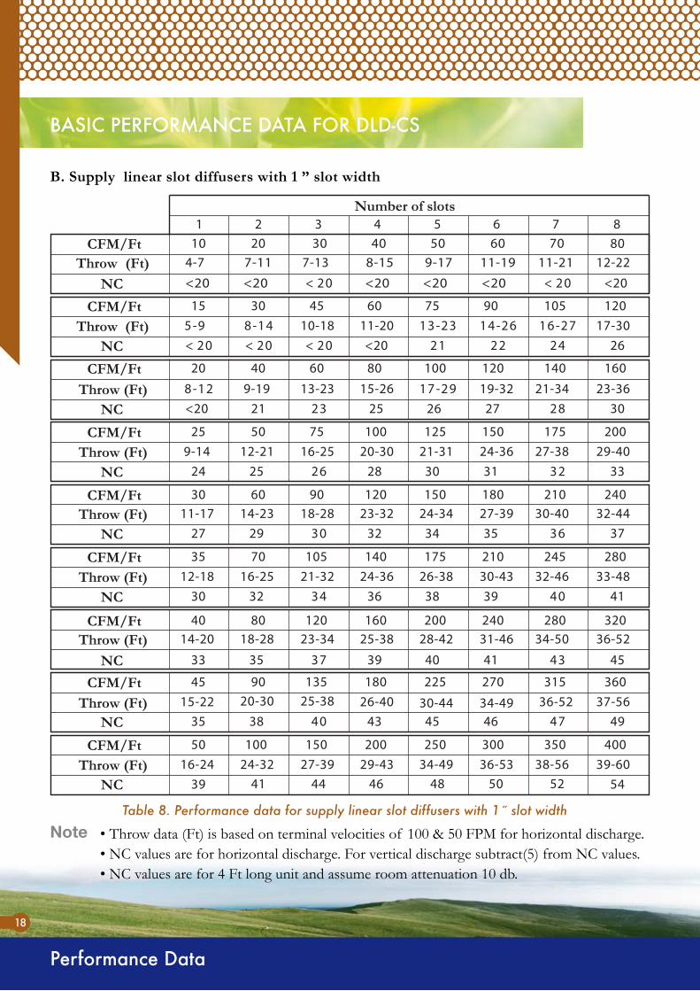
BASIC PERFORMANCE DATA FOR DLD-CS
Note
B. Supply linear slot diffusers with 1 ” slot width
17-3026
120
NC
CFM/FtThrow (Ft)
3015 45 60 75 9072-6162-4141-8
221202<02< 4202<
10532-319-5 11-2010-18
<20
23-3630
160
NC
CFM/FtThrow (Ft)
4020 60 80
19-32 21-3421 25 26 27 8232
140
92-7121-8 15-2613-23
100 120
9-19<20
29-4033
200
NC
CFM/FtThrow (Ft)
5025 7524-36 27-38
24 25 28 30 31 2362
17521-3120-3016-25125 150
12-21100
9-14
32-4437
2406030 9027-39 30-40
27 29 32 34 35 6303
21024-3423-3218-28150 180
14-23120
11-17
NC
CFM/FtThrow (Ft)
33-4841
280703530-43 32-46
30 32 36 38 39 0443
24526-3824-3621-32175 210
16-25140
12-18105
NC
CFM/FtThrow (Ft)
36-52
45
320804031-46 34-50
33 35 39 40 41 3473
28028-4225-3823-34200 240
18-28160
14-20120
NC
CFM/FtThrow (Ft)
37-5649
3609045
34-49 36-5235 38 43 45 46 7404
315
30-4426-4025-38225 270
20-30180
15-22135
NC
CFM/FtThrow (Ft)
39-6039 41 46 48 5044 52 54
400
NC
5036-53 38-56
35034-4929-4327-39250 300
24-32200
16-24150100CFM/Ft
Throw (Ft)
CFM/Ft1 2 3 4 5 6 7 8
8012-22
<20
Number of slots
NCThrow (Ft)
2010 30 40 50 60 704-7 7-137-11 8-15 9-17 11-19 11-21
<20 <20 <20 <20 <20 02<02<
Table 8. Performance data for supply linear slot diffusers with 1˝ slot width
• Throw data (Ft) is based on terminal velocities of 100 & 50 FPM for horizontal discharge.• NC values are for horizontal discharge. For vertical discharge subtract(5) from NC values.• NC values are for 4 Ft long unit and assume room attenuation 10 db.
19
Performance Data
ww
w.d
asco
.com
.kw
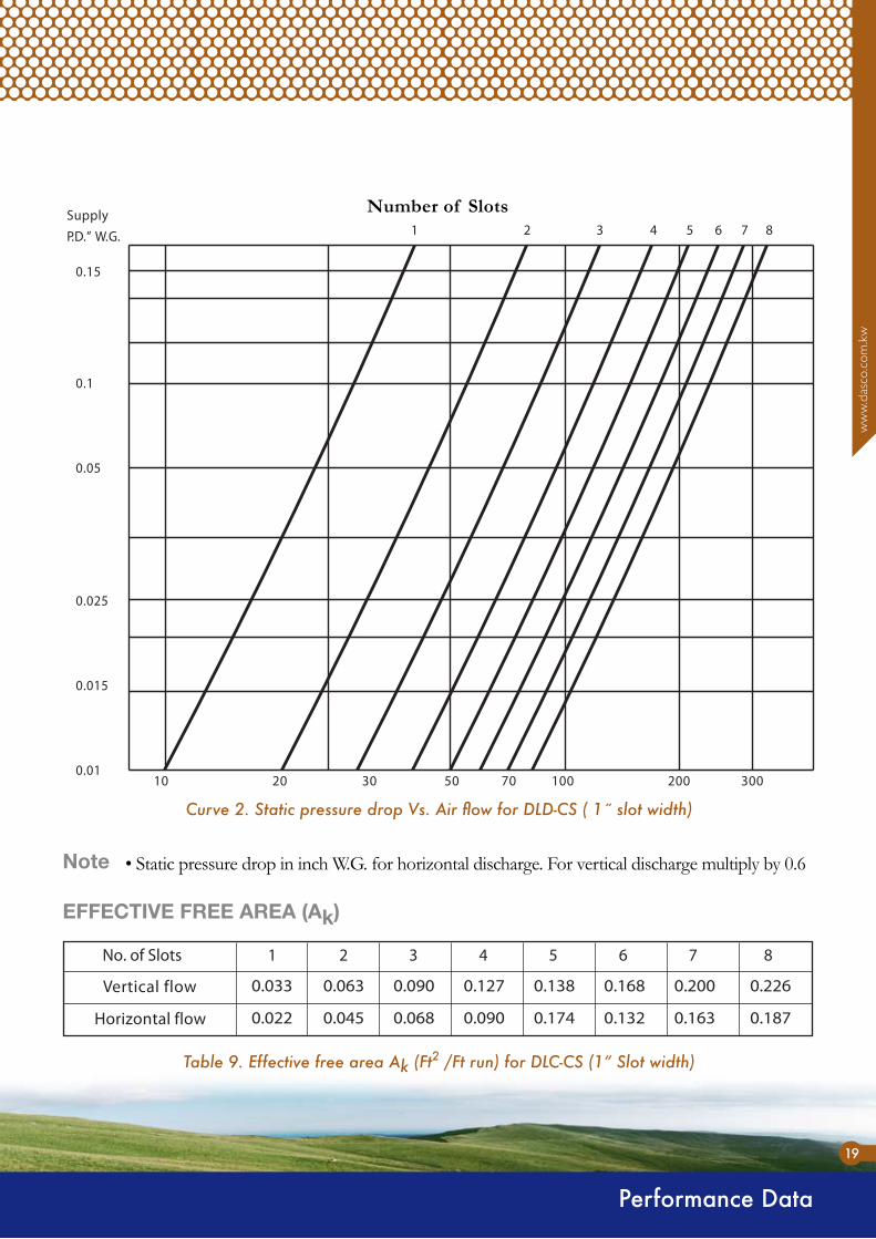
EFFECTIVE FREE AREA (Ak)
Table 9. Effective free area Ak (Ft2 /Ft run) for DLC-CS (1” Slot width)
Note • Static pressure drop in inch W.G. for horizontal discharge. For vertical discharge multiply by 0.6
Number of Slots
Curve 2. Static pressure drop Vs. Air flow for DLD-CS ( 1˝ slot width)
1 2 3 4 5 6 7 8
10 20 30 50 70 100 200 300
SupplyP.D.” W.G.
0.15
0.1
0.05
0.025
0.015
0.01

Performance Data
20
BASIC PERFORMANCE DATA FOR DLD-CR
Note
A. Return linear slot diffusers with 3/4 ” slot width
1 2 3 4 5 6 7
CFM/Ft
Static PressureDrop W.G
Number of slots
CFM/Ft
CFM/Ft 1203015 45 60 75 90 105
16040 041080602 100 120CFM/Ft
20050 5715752 125 150100CFM/Ft
24060 0120903 150 180120CFM/Ft
28070 54253 175 210140105CFM/Ft
32080 08204 200 240160120
36090 51354 225 270180135CFM/Ft
40005305 250 300200150100CFM/Ft
21 23 24 726202<20<20
21 22 26 28 29 130342
25 27 31 32 33 534392
31 33 35 36 37 938343
34 36 39 40 41 342483
37 39 43 44 45 746414
40 43 47 48 49 150554
43 45 49 51 53 755574
NC
NC
NC
NC
NC
NC
NC
NC
NC
<2002<02<02< 02<02< <20<202010 30 40 50 60 70 80
0.4520.0620.030 0.117 0.173 0.236 0.3350.007
8
Table 10. Performance data for return linear slot diffusers with 3/4˝ slot width
•Performance data are for return linear slot diffusers with deflection blades.•NC values are for 4 Ft long unit and assume room attenuation 10 db.•Static pressure values are in inches W.G.
EFFECTIVE FREE AREA (Ak)
Table 11. Effective free area Ak (Ft2 /Ft run) for DLC-CR (3/4˝ Slot width)

Note
B. Return linear slot diffusers with 1 ” slot width
CFM/Ft
Static PressureDrop W.G
Number of slots
CFM/Ft
CFM/Ft
CFM/Ft
CFM/Ft
CFM/Ft
CFM/Ft
CFM/Ft
CFM/Ft
NC
NC
NC
NC
NC
NC
NC
NC
NC
81 2 3 4 5 6 7
16040 041080602 100 120
20050 5715752 125 150100
24060 0120903 150 180120
28070 54253 175 210140105
32080 08204 200 240160120
36090 51354 225 270180135
40005305 250 300200150100
40 42 47 49 51 552554
36 39 44 46 47 059414
34 36 40 41 42 644483
31 33 37 39 40 241453
28 29 33 35 36 837313
24 26 29 31 32 433372
22 26 27 28 039242<20
20 22 23 25 26<20<20 <20
1203015 45 60 75 90 105
02<02<02< 02<02< <20 0202<802010 30 40 50 60 70
0.3100.0440.020 0.078 0.115 0.164 0.2310.005
Table 12. Performance data for return linear slot diffusers with 1 ˝ slot width
•Performance data are for return linear slot diffusers with deflection blades.•NC values are for 4 Ft long unit and assume room attenuation 10 db.•Static pressure values are in inches W.G.
EFFECTIVE FREE AREA (Ak)
Table 13. Effective free area Ak (Ft2 /Ft run) for DLC-CR (1 ˝ slot width)
21
Performance Data
ww
w.d
asco
.com
.kw
BASIC PERFORMANCE DATA FOR DLD-CR

Correction Factors
22
CORRECTION FACTORS
A) Supply Linear slot diffusers
Table 14. Correction factors for throw and NC values at different active lengths of supply linear slot diffusers
• Throw and NC values in performance tables are based on supply linear slot diffusers with active length of 4 Ft. To determine throw and NC values for other lengths, use the correction factors in the following table :
Table 16. Correction factors for NC values at different active lengths of return linear slot diffusers.
Table 15. Correction factors for static pressure drop and NC values at different damper adjustments
• Static pressure drop and NC values in performance table/curves are based on 100% damper opening . Use the following correction factors for different damper adjustments.
B) Return linear slot diffusers• NC values in performance tables are based on return linear slot diffusers with active length of 4 Ft. To determine NC values for other lengths, use the correction factors in the following table:

23
AIR BALANCING ADJUSTMENT
Air Balancing
ww
w.d
asco
.com
.kw
Right Flow
Use measuring tools for air velocity like ALNOR 2220 A or 2220 probe, or anemotherm air
meter model 60.
Take number of measuring points ( should be not less than 4)based on 4 Ft long linear dif--
fuser, and probe should be located and adjusted as to measure the maximum air velocity by
facing the probe to the air flow direction on the face of the linear slot diffuser as shown.
Take the arithmetic average of velocity readings to obtain the Vk (average) as follows:
Determine the area factor (Ak) from previous tables considering the linear diffuser length
and number of slots.
Calculate the air volume ( CFM ) with the following formula :
1)
2)
3)
4)
5)
To determine the CFM, follow up the following procedure:
DEFLECTOR SETTINGThe deflector blades of the supply linear slot diffusers can be fully adjusted to give either a hori--
zontal / vertical air pattern, or any combination of them.
The horizontal air flow adjustment may be set for either left or right hand throw.
Left Flow Vertical Flow Return
Vk ( average) =( V1+V2+.....+Vk)
K
CFM = Vk (average) x Ak
Note If the air volume calculated from above procedure is not satisfactory, repeat the same proce--dure after adjusting the deflector angle.

Fixing Method
24
Linear Diffuser (2 slots)without end caps
Linear Diffuser (2 slots)with end cap from one side
STANDARD FIXING METHOD

25
CONVERSION TABLE
Conversion Table
ww
w.d
asco
.com
.kw
Table 17. Metric guide conversion factors.
Quantity Imperial Unit Metric Unit From Imperial To From Metric To
Metric Multiply By Imperial Multiply By
Area Square foot Square meter (m2) 0.0929 10.764
Square inch Square millimeter (mm2) 645.16 0.00155
Density Pounds per cubic foot Kilograms per cubic 16.018 0.624
meter (kg/m3)
Length 4930.04.52)mm(retemillimhcni
82300.08.403)mm(retemillimtoof
8082.38403.0)m(retemtoof
8390.14419.0)m(retemdray
Pressure 9120.46842.0)aPk(lacsapoliKnmulocretawfohcni
2523.07389.2)aPk(lacsapoliKnmulocretawfotoof
4692.01473.3)aPk(lacsapoliKnmulocyrucremfohcni
6023.29034.0)aPk(lacsapoliKhcnierauqsrepsecnuo
541.08498.6)aPk(lacsapoliKhcnierauqsrepsdnuop
Temperature 23+)Cº5/9()23-Fº(9/5)Cº(suiclectiehnerhaf
Velocity feet per second meters per second (m/s) 0.3048 3.2808
feet per minute ( fpm) meters per second (m/s) 0.00508 196.85
miles per hour meters per second (m/s) 0.44704 2.2369
Volume Flow Cubic feet per minute (cfm) Liters per second (L/s) 0.4719 2.119
Cubic feet per minute (cfm) Cubic meters per second (m3/s) 0.0004719 2119.0
Cubic feet per hour ( cfh) Milliliters per second( ml/s) 7.8658 0.127133
Gallons per minute(U.S.) Liters per second( L/s) 0.6309 15.850
Gallons per minute(imperial) Liters per second( L/s) 0.7577 13.198

Different samples from DASCO air terminal devices (Linear Slot Diffusers) were tested at ITS (Intertek Testing Services) labs in accordance with:
TESTING AND APPROVAL
Testing & Approval
26
Air diffusion council test code for grilles, registers and diffusers No. ADC 1062: GRD-84.ISO 5219 “Air distribution and air diffusion laboratory aerodynamic testing and rating of air terminal devices”.ANSI/ASHRAE 70-1991, “Method of testing for rating the performance of air outlets and inlets”.
•
•
•
TESTING AND APPROVAL
LINEAR SLOT DIFFUSERS WERE TESTED FOR:
Sound (NC Noise Criteria).Static pressure in inches W.G.Throw, feet.Ak (Area factor).
a.b.c.d.

DASCO offers a first class service by introducing a wide range of perfect polyester powder coating on all of its aluminium products of air terminal devices.The best quality of polyester powder Corro-Coat are used in according to the inter--national standards (BS,ISO,DIN,ASTM). PE-F architectural grade polyester powders are used perfectly with pre-treatment, electrostatic spray and curing in accordance with the above standards recommendations. A complete range of RAL-Standard colours are always available in addition to a vast range of special compound colours as per our customers request.
COATING WITH POWDERCOATING WITH POWDER
NOW YOU CAN ACHIEVE OPTIMAL COATING PERFORMANCEON ALL PRODUCTS YOU PAINT!
27
RAL Standard Colour Chart Swatch
ww
w.d
asco
.com
.kw

28
www.dasco.com.kw

29
ww
w.d
asco
.com
.kw
www.dasco.com.kw

Since 1962
P.O. Box: 6192 Hawalli 32036 Kuwait.Tel: +965 4839911 Fax: +965 4815498
www.dasco.com.kw Prod
uct B
ulle
tin 1
33-D